
Article

Design and Simulation of a Three-DOF Profiling Header for Forage Harvesters in Hilly Terrain

1
College of Engineering, South China Agricultural University, Guangzhou 510642, China
2
Ministry of Education Key Technologies and Equipment Laboratory of Agricultural Machinery and Equipment in South China, South China Agricultural University, Guangzhou 510642, China
3
Institute of Facility Agriculture, Guangdong Academy of Agricultural Sciences, Guangzhou 510640, China
*
Author to whom correspondence should be addressed.
AgriEngineering 2026, 8(4), 145; https://doi.org/10.3390/agriengineering8040145
Submission received: 4 February 2026 / Revised: 1 April 2026 / Accepted: 4 April 2026 / Published: 8 April 2026

Abstract

To address the problems of uneven stubble height and high missed-cutting rate caused by the insufficient profiling capability of traditional forage harvesters in complex hilly terrain, this paper designs a three-degrees-of-freedom (DOF) profiling header primarily for typical hilly terrain with gentle slopes of 8–15°. Through pitch, roll, and height adjustments, it stably maintains stubble height at 150 mm. Subsequently, geometric analysis and structural optimization achieved kinematic decoupling among all degrees of freedom, thereby overcoming the inherent limitations of the two-DOF header, such as poor adaptability to longitudinal slope and strong adjustment coupling. Three-dimensional modeling was completed in SolidWorks, multibody dynamics simulation was performed in ADAMS, and a profiling control system incorporating a hydraulic system, multi-source sensor fusion, and a fuzzy PID controller was built. The dynamics simulation results show that under the working conditions of 15° longitudinal and 10° transverse slopes, the stubble height error of the header is controlled within 10%, the attitude angle adjustment error is less than 0.5°, and the dynamic response is excellent. Prototype field tests showed that, compared with the two-DOF header, the three-DOF profiling header improved the stubble height stability by about 35%, reduced the missed-cutting rate by about 5%, and increased the operating efficiency by about 15%. No cutting blade contact with the soil occurred, verifying the rationality of the mechanism design and its adaptability to terrain. This study provides an effective technical solution for improving the mechanization level of forage harvesting in hilly and mountainous areas.

1. Introduction

As a vital strategic resource in China, the sustainable utilization of grassland resources directly impacts the high-quality development of animal husbandry. Mechanized harvesting of forage is a key link in ensuring a high-quality supply of animal husbandry. However, China’s mechanization level in forage harvesting is still significantly behind that of developed countries [1,2]. Especially in mountainous and hilly areas with complex terrains, according to the definition in “Agricultural Terminology”, sloping fields can be divided into gentle slope fields (8–15°) and steep slope fields (15–25°), with gentle slope fields being the primary target of mechanized operations [3,4]. Academician Luo Xiwen further noted that hilly areas with slopes of 6–15° are suitable for the operation of small- and medium-sized agricultural machinery [5]. In such terrains, conventional forage harvesters’ headers generally suffer from insufficient profiling capabilities: existing equipment mostly adopts fixed or two-DOF adjustment mechanisms (height and roll angle adjustment), lacking pitch angle adjustment capability, resulting in uneven stubble height and increased missed-cutting rate during operation, which seriously restricts the quality and yield of forage harvesting. Moreover, two-DOF headers have inherent limitations: First, they cannot adapt to longitudinal slopes. For instance, when operating on a 15° uphill slope, the cutting plane forms an angle with the ground surface, significantly increasing the risk of interference between the cutting plane and the ground. Second, the height and posture adjustment are coupled. When attempting to alleviate the problem of the front end touching the ground by raising the overall height, the stubble height at the rear end will exceed the set value, leading to reduced consistency in stubble height and a deviation from operational requirements. Third, they have a narrow range of terrain adaptability and cannot meet the operational needs of complex terrains in hilly areas.
In terms of domestic and international research, significant technological advancements have been achieved in the field of international forage harvesting machinery [6,7]. Leading companies such as John Deere in the United States and CLAAS in Germany have pioneered intelligent headers that integrate multi-sensor fusion technology, achieving closed-loop control of header attitude through RTK-GNSS positioning and machine vision, with operational accuracy reaching the centimeter level. In contrast, domestic research mainly focuses on the improvement of two-DOF headers and the optimization of control systems. For instance, Gong et al. [8] addressed the issue of inadequate automatic height control in domestic sugarcane harvesters by designing a follow-up control system based on a self-weight oscillating profiling mechanism. Combined with an STM32 controller and a PID algorithm, this system achieved precise adjustment of header height. Field trials demonstrated that stubble height deviation could be controlled within 20 mm, while the average head breakage rate was reduced to 21%. Long et al. [9] addressed issues such as sensor susceptibility to interference and the high cost of automatic height adjustment systems for rice-wheat combined harvesters by proposing an indirect measurement method based on vehicle and header tilt angles. They established corresponding mathematical models and developed an adaptive adjustment system centered on tilt sensors. Tests showed that the maximum control error of the system was 18 mm, making it suitable for relatively flat working environments with small obstacles. Ji et al. [10] developed an automatic header height adjustment device to meet the demands of multi-crop combined harvesting, integrating a contact-type profiling mechanism with non-contact ultrasonic sensors for height detection and employing a fuzzy controller for regulation. In field trials with rapeseed, rice, and millet, the system achieved header-height control errors of no more than 15 mm. Zhao et al. [11] developed a contact-based terrain-sensing device for sugarcane harvesters. Through orthogonal experiments, they investigated the effects of three factors—operating speed, rotational torque, and preload force—on terrain height detection performance. They proposed an evaluation metric system centered on the Fréchet distance and residual standard deviation. Ni et al. [12] designed an adaptive header-height adjustment system for soybean harvesting to address common issues, such as missed cutting and soil contact. They focused on analyzing the interaction between soil and the profiling mechanism, established a relationship model between the angle sensor reading and the profiling mechanism’s rotation angle, and developed a calculation method for header profiling height based on soil compaction data. Field trial results showed that the absolute error between the actual average stubble height and the set value was less than 2 mm.
As the core working component of forage harvesters, the header directly contacts the crop and terrain, and its profiling performance fundamentally determines harvesting quality. In agricultural applications, headers typically possess three degrees of freedom—height adjustment, roll angle adjustment, and pitch angle adjustment—each critical for adapting to complex terrain: height adjustment maintains a constant stubble height; roll angle adjustment compensates for lateral slopes; and pitch angle adjustment ensures the cutting plane remains parallel to longitudinal slopes. However, current domestic research on header profiling technology has not yet overcome the limitations of two-DOF systems [13,14,15,16,17,18,19,20]. Although significant progress has been made, the following common limitations still exist: (1) Lack of longitudinal slope adaptability: none of the studies involve dynamic pitch angle adjustment, failing to address slope variations in the forward direction; (2) Unresolved adjustment coupling issues: the coupling between height adjustment and roll adjustment leads to decreased stubble height consistency during lateral leveling; (3) Limited terrain adaptability: the operational terrains validated in existing studies are mostly flat fields or relatively flat environments with small obstacles, lacking targeted validation for typical hilly slopes (8–15°). In contrast, although intelligent headers from leading international companies have achieved multi-sensor fusion and closed-loop control, their technical details are often undisclosed, and the equipment costs are high, making them difficult to directly adapt to the development needs of small and medium-sized agricultural machinery in hilly areas of China. Therefore, developing a three-DOF profiling header that adapts to the terrain characteristics of hilly areas in China, possesses pitch adjustment capability, and features motion decoupling holds significant theoretical importance and engineering application value.
Therefore, this paper proposes a three-DOF profiling header design scheme. Based on the analysis of the principle of the three-DOF robotic arm, the adaptability of the header to the terrain of hilly and mountainous areas, and the agronomic requirements of typical pasture stubble retention, the key design indicators are determined, and the detailed design of the adjustment mechanism of each degree of freedom is completed. On this basis, a profiling control system incorporating a hydraulic drive system, multi-source sensor fusion, and a fuzzy PID controller is constructed to achieve real-time closed-loop adjustment of the header attitude. Subsequently, through virtual prototype simulation, hydraulic system simulation, and field trials, the profiling performance and operational effectiveness of this header under complex terrain were systematically evaluated, validating its design rationality and practicality and providing a new technical solution to improve the terrain adaptability of forage harvesting machinery.

2. Mechanism Design of the Three-DOF Profiling Header

2.1. Design Basis and Parameter Determination

The core objective of this design is to enable the header to adapt to hilly and mountainous terrain with slopes ≤15° while maintaining a stable stubble height within a reasonable range to ensure the quality of forage regeneration. Based on the “Agronomic Terminology” and Academician Luo Xiwen’s definition of the scope of mechanized operations in hilly areas [3,5], the target terrain for operations is determined to be a gently sloping field with a slope of 8–15°. To cover this slope range while allowing for adjustment margins, both the header’s pitch angle and roll angle adjustment ranges are set to ±15°. Integrating the agronomic requirements for regeneration of typical pasture grasses in hilly and mountainous terrain [21] with the general technical specifications for mechanized harvesting, the target stubble height is set at 150 mm. Accordingly, the vertical lifting stroke is determined to be 0–250 mm, providing sufficient dynamic adjustment margin. Based on the above design specifications, the following sections will provide a detailed design of the adjustment mechanism for each degree of freedom [22,23,24].

2.2. Structure of Three-DOF Adjustment Mechanism for Header

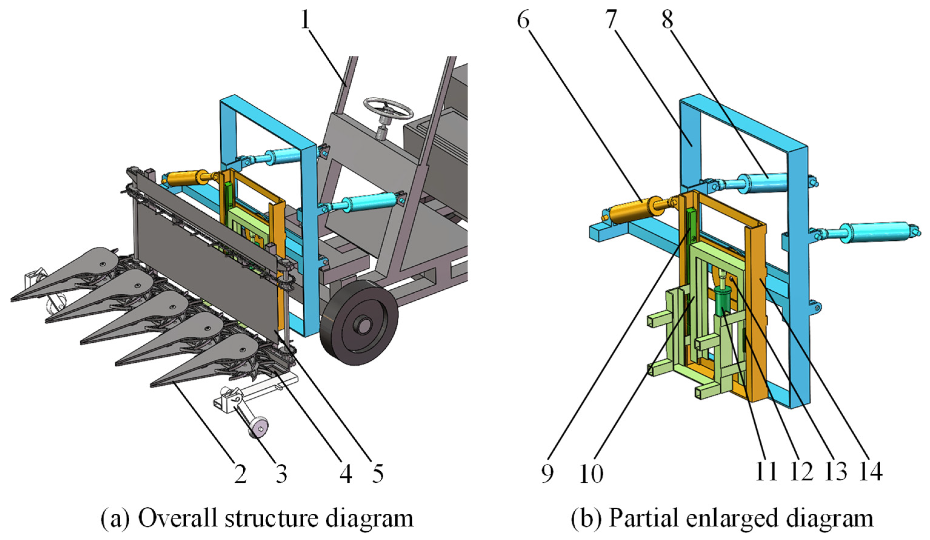
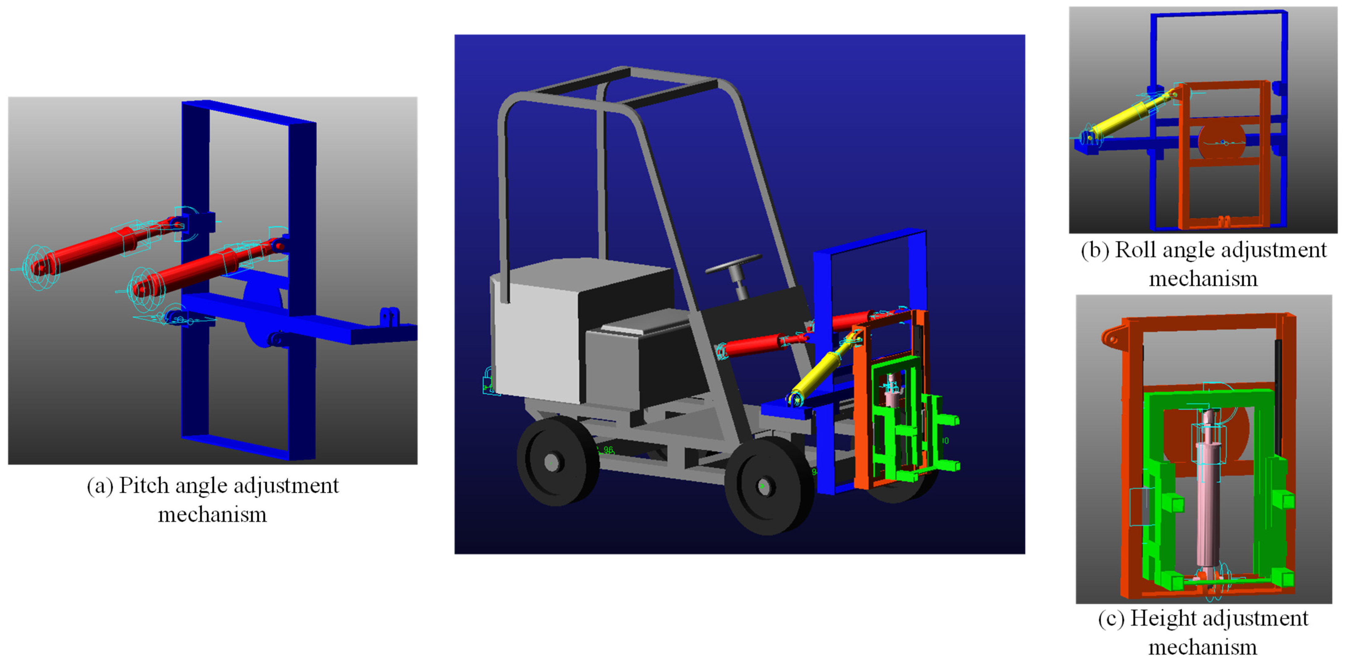
The three-DOF header is a spatially-serial adjustment mechanism comprising a height adjustment module, a roll angle adjustment module, and a pitch angle adjustment module. These three modules correspond to the header’s height from the ground, roll angle, and pitch angle, respectively. Furthermore, they achieve motion decoupling through independent motion paths, eliminating interference coupling. This design not only overcomes the inherent limitations of existing two-DOF headers but also achieves longitudinal slope adaptability, decoupled adjustment, and precise adaptation to complex hilly terrain through its motion-decoupling mechanism. It provides reliable assurance for the efficient operation of forage harvesters in complex hilly terrain. The header’s structure is shown in Figure 1, which primarily consists of a height adjustment mechanism, a roll angle adjustment mechanism, a pitch angle adjustment, a profiling device, frames, and a hydraulic control system; Figure 1a depicts the overall structure of the vehicle and header, while Figure 1b highlights the three-DOF header section.

2.3. Design of the Key Adjustment Mechanism

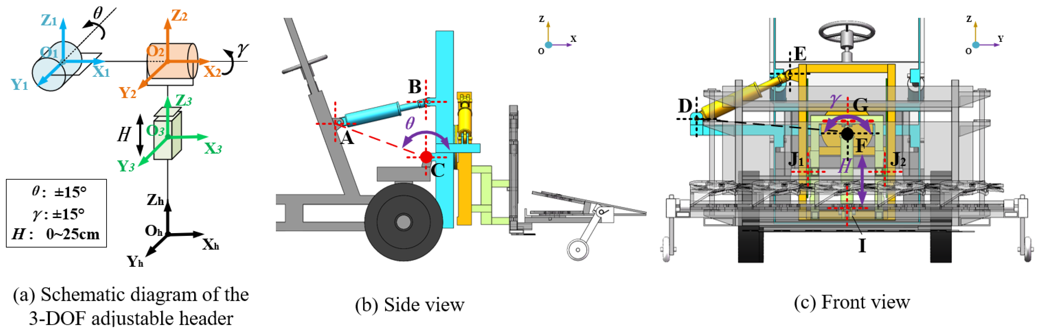
To achieve independent and decoupled adjustment of the three degrees of freedom of pitch, roll, and height, this design adopts a series of spatial adjustment mechanisms, whose integrated structure is shown in Figure 2. Figure 2a is a schematic diagram of the mechanism’s motion principle, where the O h - X h Y h Z h coordinate system represents the header’s center-of-mass coordinate system. It visually illustrates the motion directions and drive component layouts of pitch angle adjustment (rotation around the Y -axis), roll angle adjustment (rotation around the X-axis), and height adjustment (lifting along the Z-axis); Figure 2b, c present the side view and front view of the mechanism, respectively, clearly illustrating the spatial layout of each actuator, hinge positions, and the connection relationships of key components. This provides a comprehensive geometric and structural foundation for subsequent kinematic and mechanical analysis.
(1)
Design of Pitch Angle Adjustment Mechanism
The core function of this mechanism is to compensate for the longitudinal slope in the forward direction, ensuring that the cutting plane remains parallel to the slope surface. As shown in Figure 2b, the mechanism adopts a four-bar linkage configuration symmetrically driven by dual hydraulic cylinders. The gantry frame is connected to the vehicle via the rear hinge point C. Two identical hydraulic cylinders AB are symmetrically arranged on both sides of the gantry frame, with cylinder bodies hinged at the fixed-point A on the vehicle body and piston rods hinged at the moving-point B on the gantry frame. When both cylinders extend and retract synchronously under control, they jointly drive the gantry frame to rotate around point C, enabling precise adjustment of the longitudinal pitch angle θ of the header. This symmetrical layout ensures high rigidity and resistance to eccentric loads in the drive system. Based on the target pitch angle adjustment range, the theoretical stroke requirements for the corresponding pitch hydraulic cylinder are determined by optimizing the layout of each hinge point, while ensuring balanced driving torque and smooth movement.
(2)
Design of Roll Angle Adjustment Mechanism
This mechanism compensates for lateral slope during operation, maintaining the header’s horizontal orientation. As shown in Figure 2c, the mechanism adopts a single hydraulic-cylinder drive scheme based on a slewing bearing. An integral thrust bearing serves as the rotation center F, connecting the upper pitch gantry frame to the lower fixed support. The roll angle adjustment hydraulic cylinder DE is arranged laterally, with its cylinder body hinged at point D on the side wall of the gantry frame and its piston rod hinged at point E on the support. The hydraulic cylinder’s extension and retraction drive the gantry frame to rotate around point F, thereby adjusting the header’s roll angle γ. The mechanism possesses a large lever arm, enabling it to overcome the overturning moment generated by the header’s gravity with a minimal driving force. Based on the set roll angle adjustment range, the theoretical stroke requirement for the corresponding roll angle adjustment hydraulic cylinder is determined through kinematic analysis.
(3)
Design of Height-Adjusting Mechanism
This mechanism is responsible for controlling the overall height of the header off the ground, which serves as the benchmark for maintaining the target stubble height. To avoid the height and attitude coupling caused by traditional linkage mechanisms, this design uses a sliding pair consisting of a guide rail and sliders to achieve pure vertical lifting. As shown in Figure 2c, two vertical guide rails are fixed to the gantry frame and rigidly connected to the adjustable-height frame via symmetrically arranged sliders J1 and J2. The hydraulic height-adjustment cylinder GI has its cylinder body hinged at point G, and its piston rod hinged at point I on the adjustable-height frame. The extension and retraction of the hydraulic cylinder directly drive the sliders, causing the header to move vertically along the guide rails. By optimizing hinge-point layouts, the displacement is made to exhibit an approximately linear relationship with the cylinder’s extension and retraction, which greatly simplifies the height control model. Based on the target stubble height and terrain adaptation requirements, the theoretical stroke required for the corresponding height adjustment hydraulic cylinder is determined.

2.4. Working Principle

The height, roll angle, and pitch angle adjustment mechanisms of the header are all hydraulically driven. When the forage harvester is in operation, the sensors mounted on the profiling device at the front of the header capture the height and angle differences of the ground undulations in real time, generate terrain displacement signals, and transmit them to the hydraulic control system. The control system determines the adjustment target of the profiling header through information processing. When the profiling adjustment system switch of the profiling header is triggered, the hydraulic cylinders of the three-DOF adjustment mechanism begin operation, drive the header to move, and adjust the header’s height from the ground, roll angle, and pitch angle to the expected position. The working principle of the 3-DOF header is shown in Figure 3.

3. Construction of the Header Profiling System

3.1. Construction of the Hydraulic System

3.1.1. Overall Design of the Hydraulic System

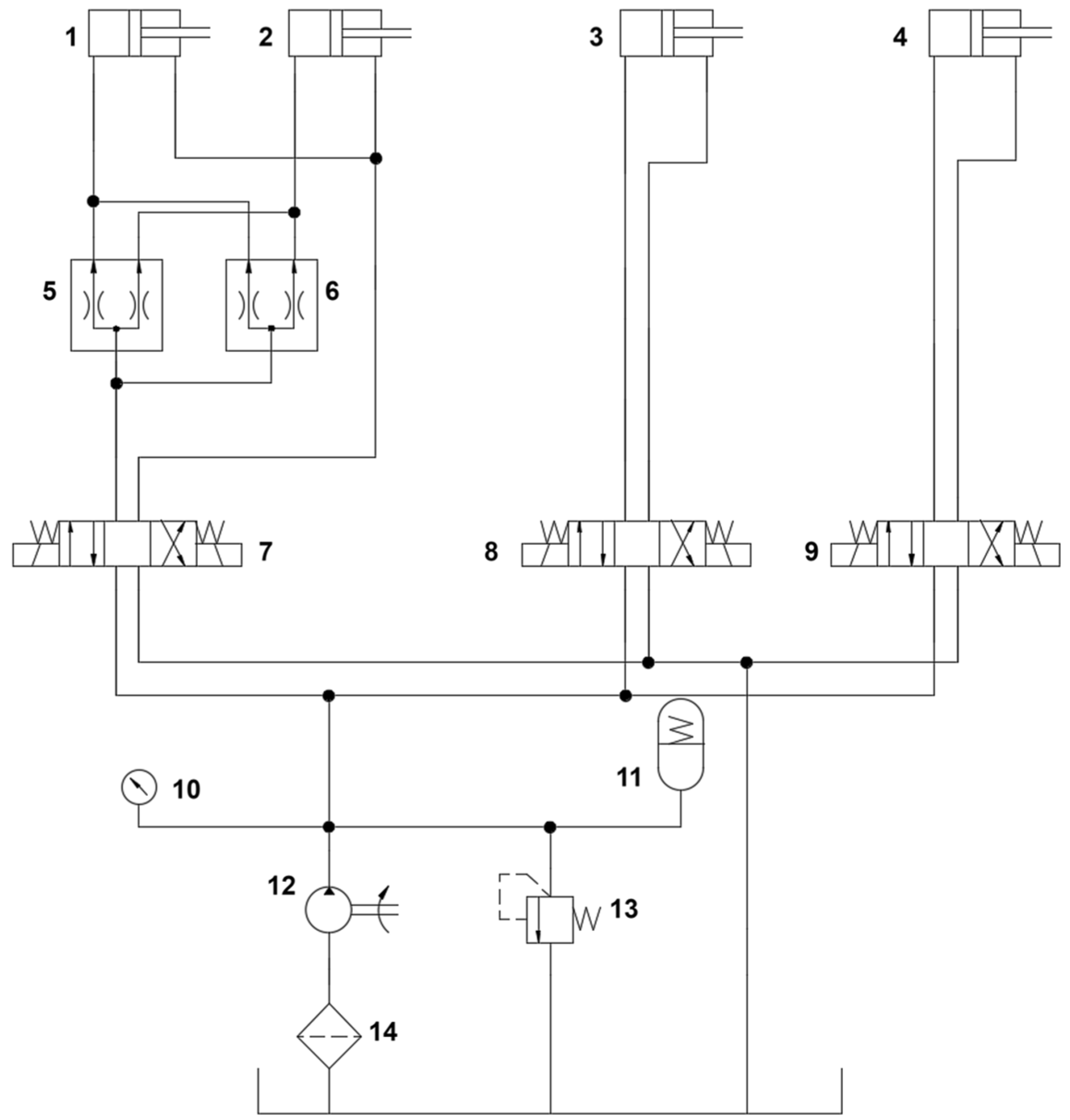
Based on the adjustment requirements of the three-DOF profiling header, a hydraulic system, as shown in Figure 4, was designed. The system consists of a hydraulic pump, relief valve, three-position four-way electro-hydraulic proportional directional valves, flow divider-combiner valves (sync valves), counterbalance valves, flow control valves, hydraulic cylinders, and hydraulic lines.
The pitch adjustment of the header is driven by a set of symmetrically arranged double-acting hydraulic cylinders (1 and 2 in the Figure 4). To ensure synchronous action of the two cylinders, a flow divider-combiner valve (sync valve, 5 and 6, in the Figure 4) is connected in series in the circuit, with the two cylinders connected in parallel downstream of the sync valve. The sync valve forcibly distributes the inlet and outlet flows, keeping the flow rate to both cylinders consistent and eliminating synchronization issues caused by load differences, leakage, or other factors, ensuring smooth, non-skewed pitch movement of the header. The core control element of this circuit is the three-position four-way electro-hydraulic proportional directional valve (7 in the Figure 4), which controls flow direction and rate by adjusting the spool opening, enabling precise pitch angle adjustment.
The roll angle adjustment of the header is achieved by a single double-acting hydraulic cylinder (3 in the Figure 4), and the height adjustment is achieved by another single double-acting hydraulic cylinder (4 in the Figure 4). Both are controlled by independent three-position four-way electro-hydraulic proportional directional valves (8 and 9 in the Figure 4). The single-cylinder drive scheme simplifies the circuit structure and reduces the complexity of synchronization control. At the same time, the flow regulation characteristics of the proportional valves enable precise control of the cylinder’s speed and displacement, meeting the dynamic adjustment requirements for roll angle and height.
The system power source is provided by a fixed displacement hydraulic pump (12 in the Figure 4). Hydraulic oil enters the pump after passing through a suction filter (14 in the Figure 4), preventing contaminants from damaging components. A relief valve (13 in the Figure 4) sets the maximum working pressure of the system to prevent overload. A pressure gauge (10 in the Figure 4) monitors system pressure in real time, and an accumulator (11 in the Figure 4) absorbs hydraulic shocks and stabilizes system pressure, improving the smoothness of dynamic response.
The three sets of three-position four-way electro-hydraulic proportional directional valves (7, 8, and 9 in the Figure 4) receive control signals from the STM32 main control unit, achieving independent control of each degree of freedom: the pitch circuit uses a sync valve with dual cylinders for synchronous drive; the roll angle and height circuits use single cylinders with proportional valves for precise adjustment. The overall scheme balances action synchronization, control accuracy, and system reliability, suitable for the profiling operation requirements in the complex terrain of hilly areas in Southern China [25].

3.1.2. Mechanical Analysis and Parameter Determination of Key Actuating Components

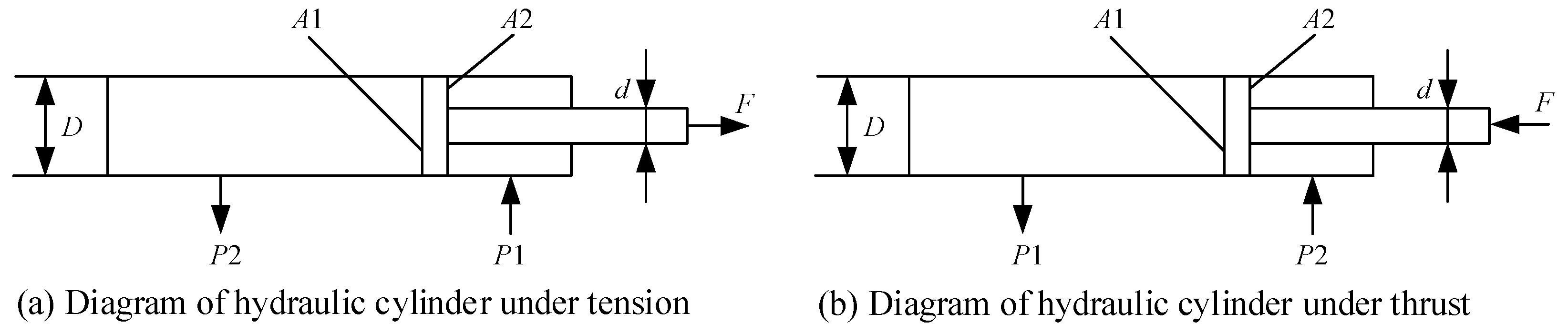
To ensure that the three-DOF header mechanism possesses the required driving capability and dynamic response performance, it is necessary to conduct a mechanical analysis of its core actuators—three sets of hydraulic cylinders—to determine key performance parameters. Based on the load conditions of each mechanism under the extreme design posture, combined with the SolidWorks 2024 quality assessment function. The rated working pressure of the hydraulic system is set to p 1 = 6   M P a [26]. The force analysis of the hydraulic cylinder is shown in Figure 5.
When the hydraulic cylinder extends, the following applies:
  p 1 A 1 p 2 A 2 = F η c m
When the hydraulic cylinder retracts, the following applies:
  p 1 A 2 p 2 A 1 = F η c m
where p 1 is the pressure in the working chamber of the hydraulic cylinder, in Pa; p 2 is the pressure in the return chamber of the hydraulic cylinder, in Pa. A 1 is the effective area of the rodless chamber of the hydraulic cylinder, in m 2 , calculated as A 1 = π D 2 / 4 ; A 2 is the effective area of the rod chamber of the hydraulic cylinder, in m 2 , calculated as A 2 = π d 2 / 4 ; D is the inner diameter of the hydraulic cylinder, in m, d is the diameter of the piston rod, in m; where F is the maximum load, in N , η c m is the mechanical efficiency of the hydraulic cylinder, taken as 0.90. Based on experience, the return oil pressure p 2 and the ratio of the diameter of the hydraulic cylinder piston and piston rod d / D are selected as 0.5 MPa and 0.55, respectively. Then, Formulas (1) and (2) determine the inner diameter of the hydraulic cylinder as follows:
D = 4 F π η c m [ p 1 ( 1 ( d / D ) 2 ) p 2 ]
(1)
Selection of Pitch Angle Adjustment Hydraulic Cylinder
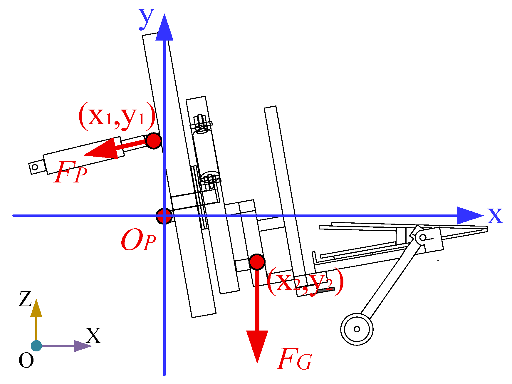
The basic structural dimensions and model of the pitch angle adjustment hydraulic cylinder are determined based on the maximum load force. As shown in Figure 6, an O P x y coordinate system is established with the center of the rotation axis as the origin O P . Gravity is applied at F G , and the center of mass of the header is located at ( x 2 , y 2 ). When the header is horizontal, the center of mass of the header and the rotation center are in the same vertical direction. When the hydraulic cylinder retracts, the header tilts upward, causing the center of mass to “shift upward”. When the hydraulic cylinder extends, the header tilts downward, causing the center of mass to “shift downward”.
As shown in the diagram above, when the hydraulic cylinders are retracted to their shortest length, they have the maximum pulling force F P , and the center of mass of the header shifts upward to the position ( x 2 , y 2 ), satisfying the following:
F P · s i n θ · x 1 F P · c o s θ · y 1 = F G x 2
where θ is the angle between the pitch angle adjustment hydraulic cylinder and the horizontal plane; F P is the total force of the dual hydraulic cylinders.
Using the quality assessment function of SolidWorks, the gravity of the load-related components is obtained as F G = 5880   N . When the hydraulic cylinder extends to its maximum length, ( x 2 , y 2 ) = (248.2, −89.3), and the coordinate of the thrust application point of the hydraulic cylinder is ( x 1 , y 1 ) = (−81.1, 299.2). The angle θ between the hydraulic cylinder and the horizontal plane is 14.03°. According to Formulas (3) and (4), F P = 4791.2   N and D = 31   m m , the maximum tensile force per hydraulic cylinder is F p 2 = 2395.6   N . The stroke of the pitch hydraulic cylinder is determined based on the maximum required pitch angle of the header. From a 3D kinematic simulation in SolidWorks, when the header is pitched to its designed limit angle, the simulation indicates a theoretical stroke requirement of 150 mm for the roll hydraulic cylinder. The specific parameters for the pitch hydraulic cylinder are presented in Table 1.
(2)
Selection of Roll Angle Adjustment Hydraulic Cylinder
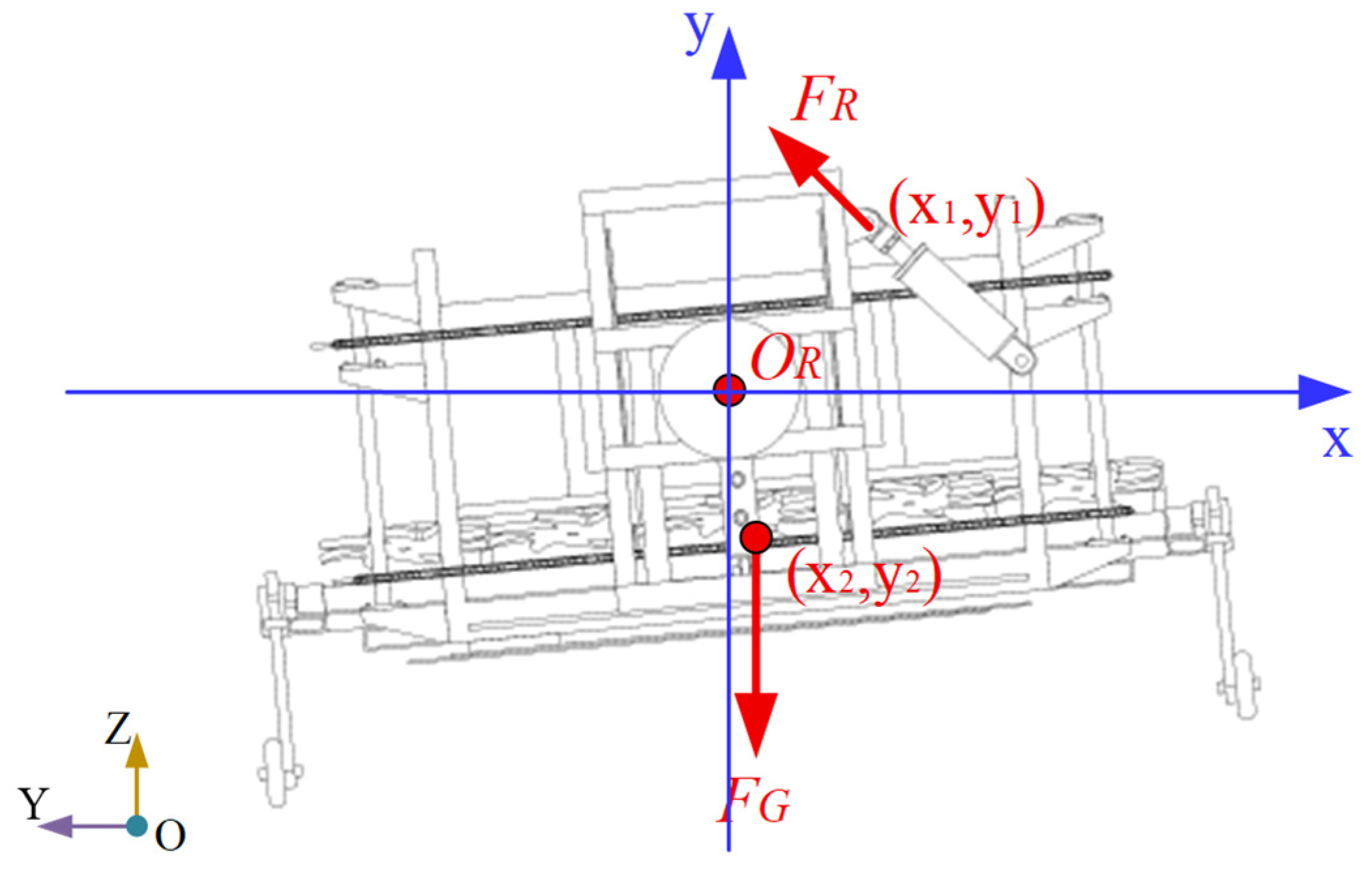
The basic structural dimensions and model of the roll angle adjustment hydraulic cylinder are determined based on the maximum load force. As shown in Figure 7, an O R x y coordinate system is established with the center of the rotation axis as the origin O R . Gravity is applied at F G , and the center of mass of the header is located at ( x 2 , y 2 ). When the header is horizontal, the center of mass of the header and the rotation center are in the same vertical direction. When the hydraulic cylinder retracts, the header tilts leftward, causing the center of mass to “shift right”; when the hydraulic cylinder extends, the header tilts rightward, causing the center of mass to “shift left”.
As shown in the diagram above, when the hydraulic cylinder is extended to its maximum length, it has the maximum thrust F R , and the center of mass of the header shifts rightward to the position ( x 2 , y 2 ), satisfying the following:
  F R · s i n γ · x 1 F R · c o s γ · y 1 = F G x 2
where γ is the angle between the roll angle adjustment hydraulic cylinder and the horizontal plane.
Using the quality assessment function of SolidWorks, the gravity of the load-related components is obtained as F G = 3920   N . When the hydraulic cylinder extends to its maximum length, ( x 2 , y 2 ) = (85.7, −255.3), and the coordinate of the thrust application point of the hydraulic cylinder is ( x 1 , y 1 ) = (125.4, 320.1). The angle γ between the hydraulic cylinder and the horizontal plane is 12.5°. According to Formulas (3) and (5), the hydraulic cylinder has F R = 1240.8   N . The stroke of the roll hydraulic cylinder is determined based on the maximum roll angle requirements of the header. SolidWorks 3D kinematic analysis confirms that the roll hydraulic cylinder requires a theoretical stroke of 150 mm to reach the maximum design tilt angle. The specifications of this cylinder are detailed in Table 1.
(3)
Selection of Height Adjustment Hydraulic Cylinder
The height adjustment hydraulic cylinder primarily controls the vertical movement of the header. Using the quality assessment function of SolidWorks, the gravity of the load-related components is obtained as F G = 3920   N . Since the lifting motion is vertical, the force acts as a linear axial pressure. The piston diameter can be directly calculated from the piston area and hydraulic pressure. According to Formula (3), the calculated value D = 43.1   m m . Similarly, the basic parameters of the height adjustment hydraulic cylinder are determined, as shown in Table 1.

3.1.3. Hydraulic Simulation Analysis

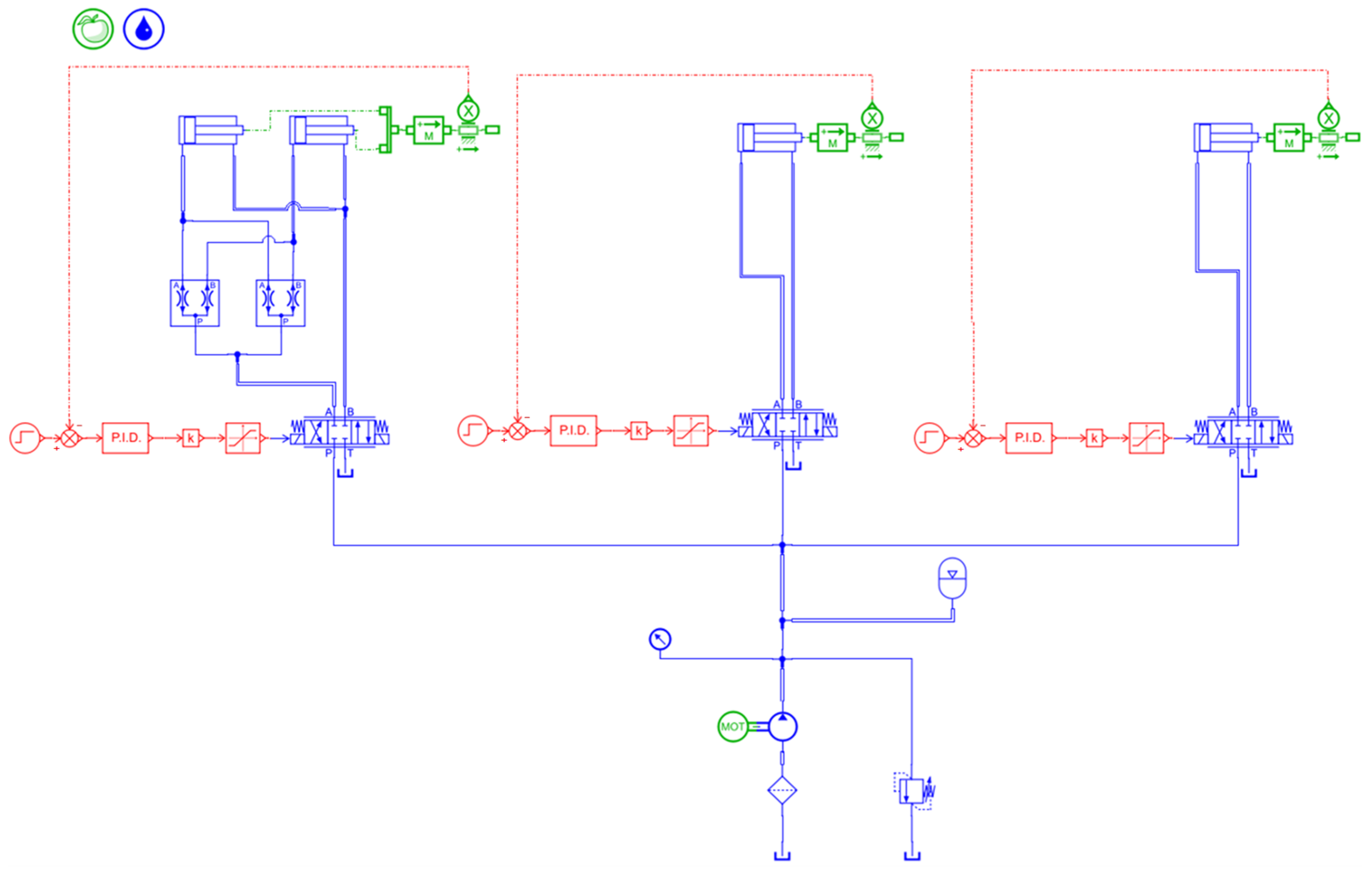
To verify the dynamic response characteristics and control performance of the three-DOF profiling header hydraulic system, a hydraulic system simulation model consistent with the physical prototype parameters was built in Amesim 2024, as shown in Figure 8. The model includes a hydraulic pump, relief valve, three-position four-way electro-hydraulic proportional directional valves, counterbalance valves, flow control valves, and the three sets of hydraulic cylinders for pitch, roll, and height, with parameters set according to the actual selections.
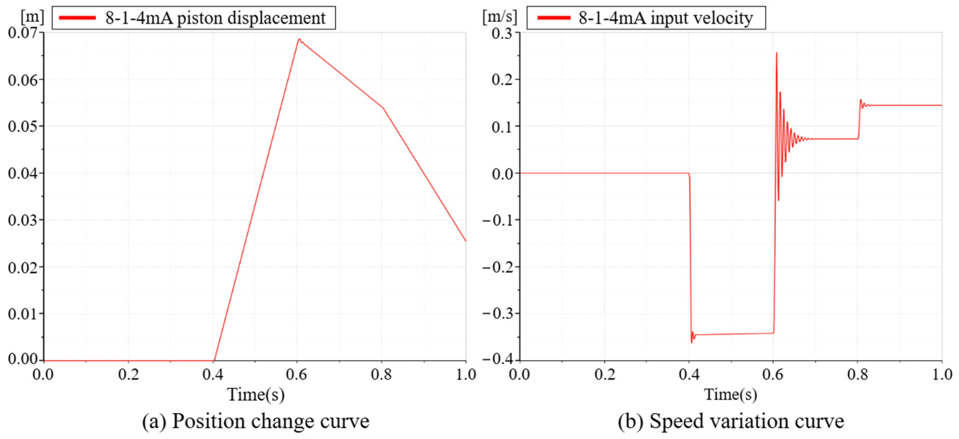
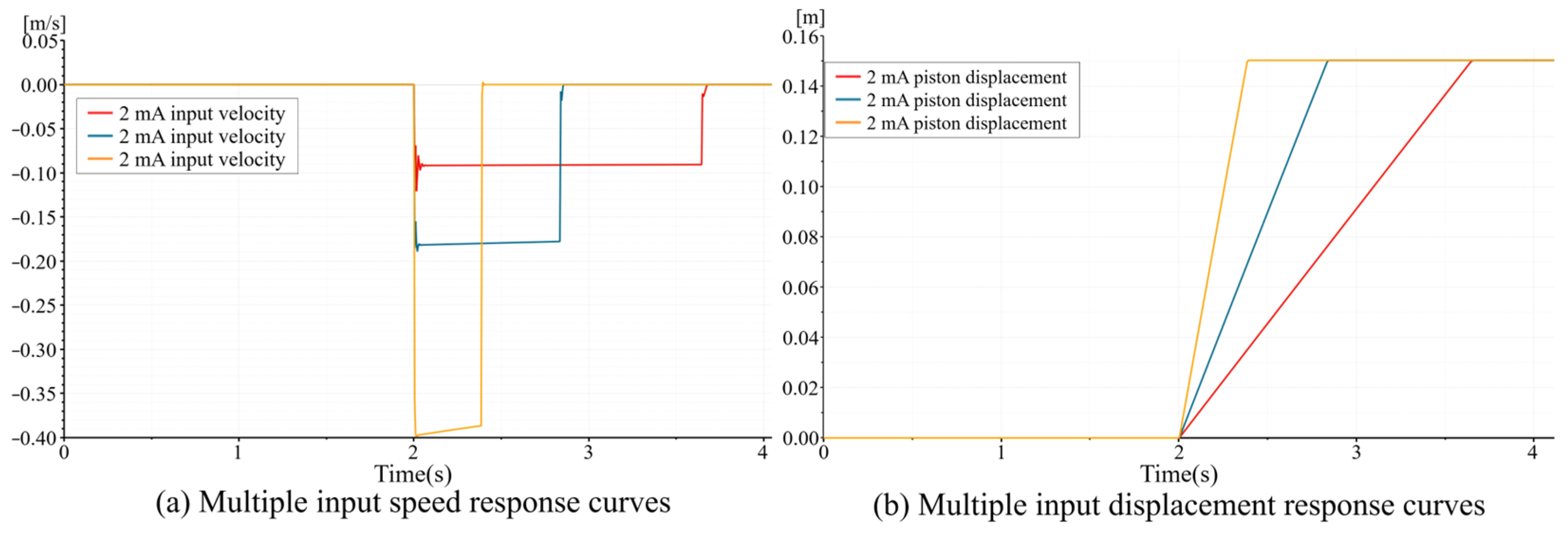
The simulation first conducted speed open-loop response tests. The results (Figure 9) show a good linear relationship between the proportional valve input current and the hydraulic cylinder movement speed, with a steady-state speed of 0.39 m/s at 9 mA current, verifying the linear controllability of the system. Speed-switching response simulations (Figure 10) show that the system exhibits typical underdamped second-order characteristics under step commands, with fast response and no severe shocks, indicating good dynamic damping capability. Under a heavy load condition of 304 kg, PID position closed-loop simulations were performed. The system’s response to a 0.12 m step displacement had an overshoot of about 8.5%, a settling time of about 3 seconds, and a steady-state error of less than 2 mm, meeting the basic requirements for position control accuracy in profiling operations. The simulation results validate the rationality of the hydraulic system design and provide reliable data support for subsequent parameter tuning and optimization of the fuzzy PID control algorithm.

3.2. Sensor System Design and Signal Processing

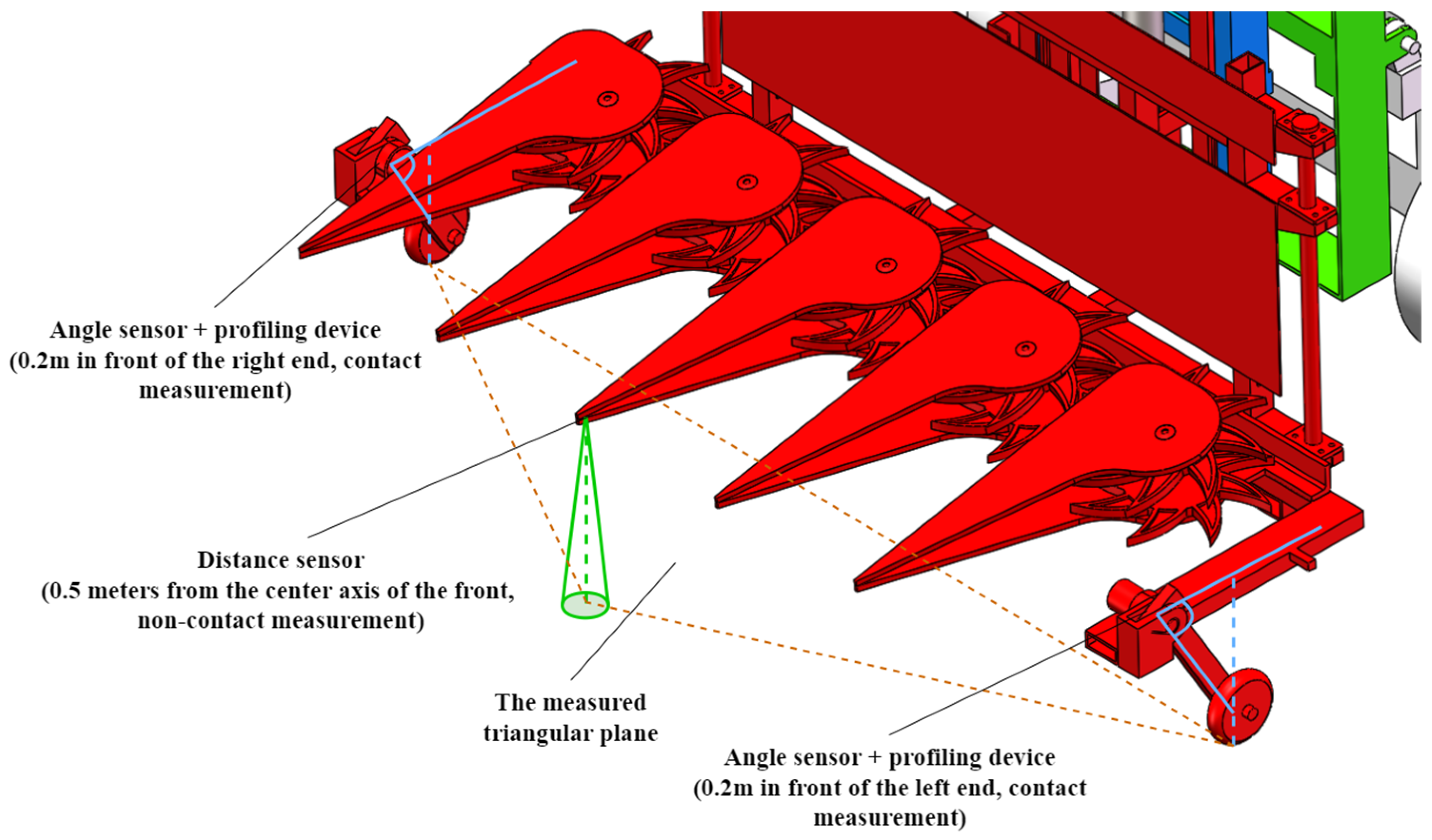
To address the operational environment characterized by severe terrain undulations and high forage coverage in the hilly areas of Southern China, this study designed a multi-source fusion terrain perception scheme combining “TOF laser ranging + contact-type profiling wheel angle measurement,” as shown in Figure 11. Regarding sensor selection, the TOF050F TOF laser ranging sensor (OHY, Shenzhen, China; range: 50 cm, accuracy: ±2 cm) was used to achieve non-contact, advanced prediction of the terrain in front of the header. The P3022 Hall-type angle sensor (Pandauto, Taiwan, China; range 360°, resolution 0.1°) was used to detect the deflection angle of the profiling wheel in real time, allowing for the calculation of the header’s ground clearance on both sides.
The sensor spatial layout adopts a triangular distribution: two angle sensors are installed on the left and right profiling wheels of the header, and the TOF laser sensor is installed on the central axis 0.5 m in front of the header. This layout reduces the risk of collective contamination of measurement data from local interference sources through heterogeneous spatial sampling, while endowing the system with early warning capability for the terrain ahead.
The stable acquisition of sensor data is uniformly scheduled by the STM32F103C8T6 (STMicroelectronics, Geneva, Switzerland) main control chip. The P3022 Hall-type angle sensors on the left and right sides of the header are sampled synchronously via ADC channels, with a sampling frequency set to 1 kHz. Synchronous sampling mode is adopted to ensure the temporal consistency of data from both sides. The TOF050F TOF laser ranging sensor communicates with the main control chip via a serial port, with the following communication parameters set to a baud rate: 115,200 bps, 8 data bits, 1 stop bit, no parity, and a sampling frequency of 50 Hz. During field operations, sensor signals are inevitably disturbed by factors such as engine vibration, ground impact, and forage sway, introducing high-frequency noise into the raw measurement data. To ensure the stability and accuracy of the control system, effective filtering of the sensor signals is necessary. This study employed a second-order active low-pass filter for hardware filtering of the raw signals, with a cutoff frequency set to 100 Hz, which can effectively suppress high-frequency vibration noise in the field while preserving the main frequency components of terrain changes. To further enhance signal quality, a Kalman filter algorithm [27] was introduced for software processing on top of hardware filtering. This algorithm achieves optimal estimation of the system state in the presence of measurement noise and system uncertainty through two steps: state prediction and measurement update, effectively reducing random interference in complex field environments and improving the stability and reliability of the measurement data.

3.3. Control System Design

The header control system adopts a layered architecture, including a perception layer, a decision layer, and an execution layer, forming a complete “perception-decision-execution-feedback” closed-loop control loop [28].
The perception layer consists of the multi-source sensors described in Section 3.2, collecting terrain data and header attitude information in real time. The raw signals are input to the decision layer after second-order low-pass filtering.
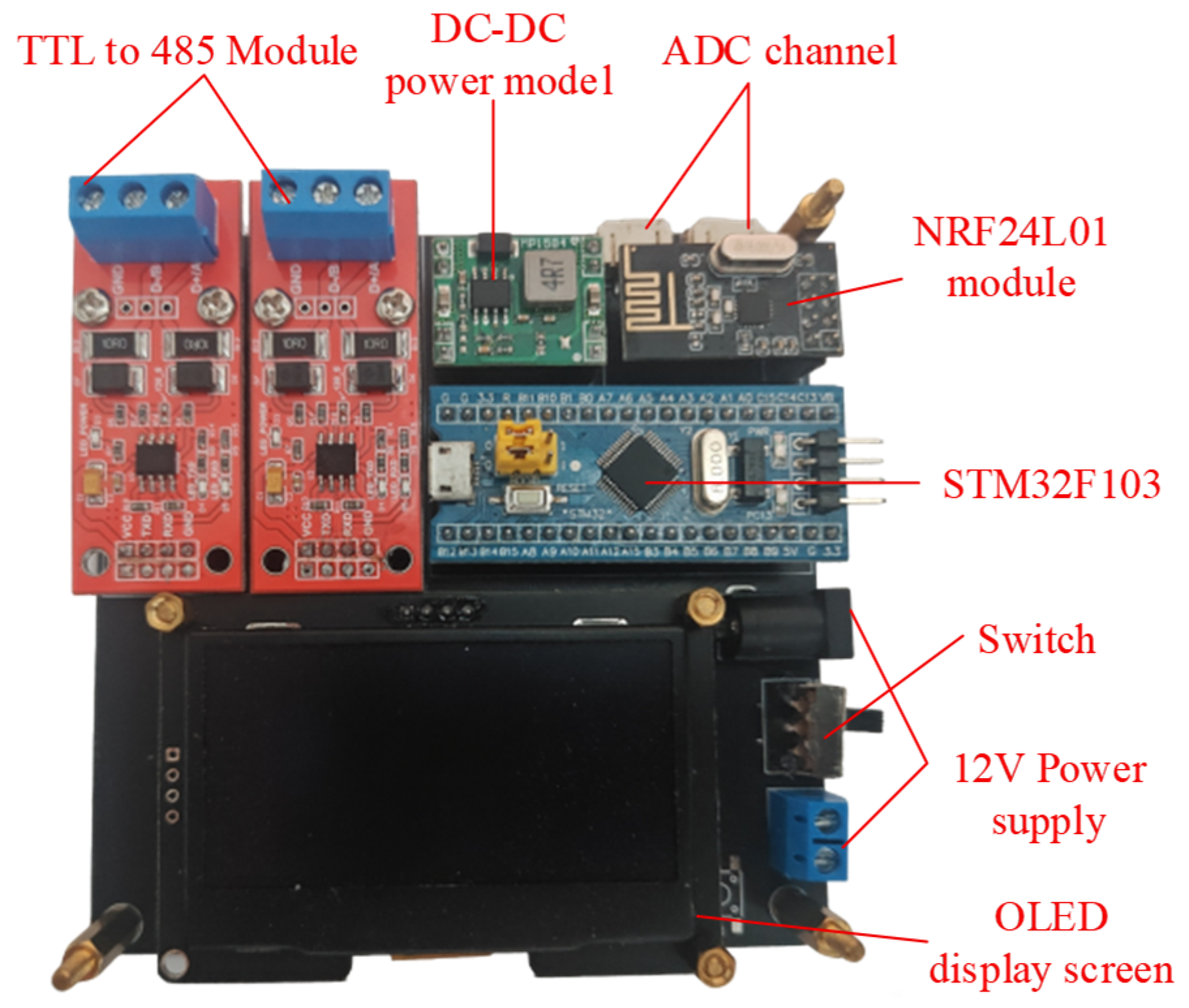
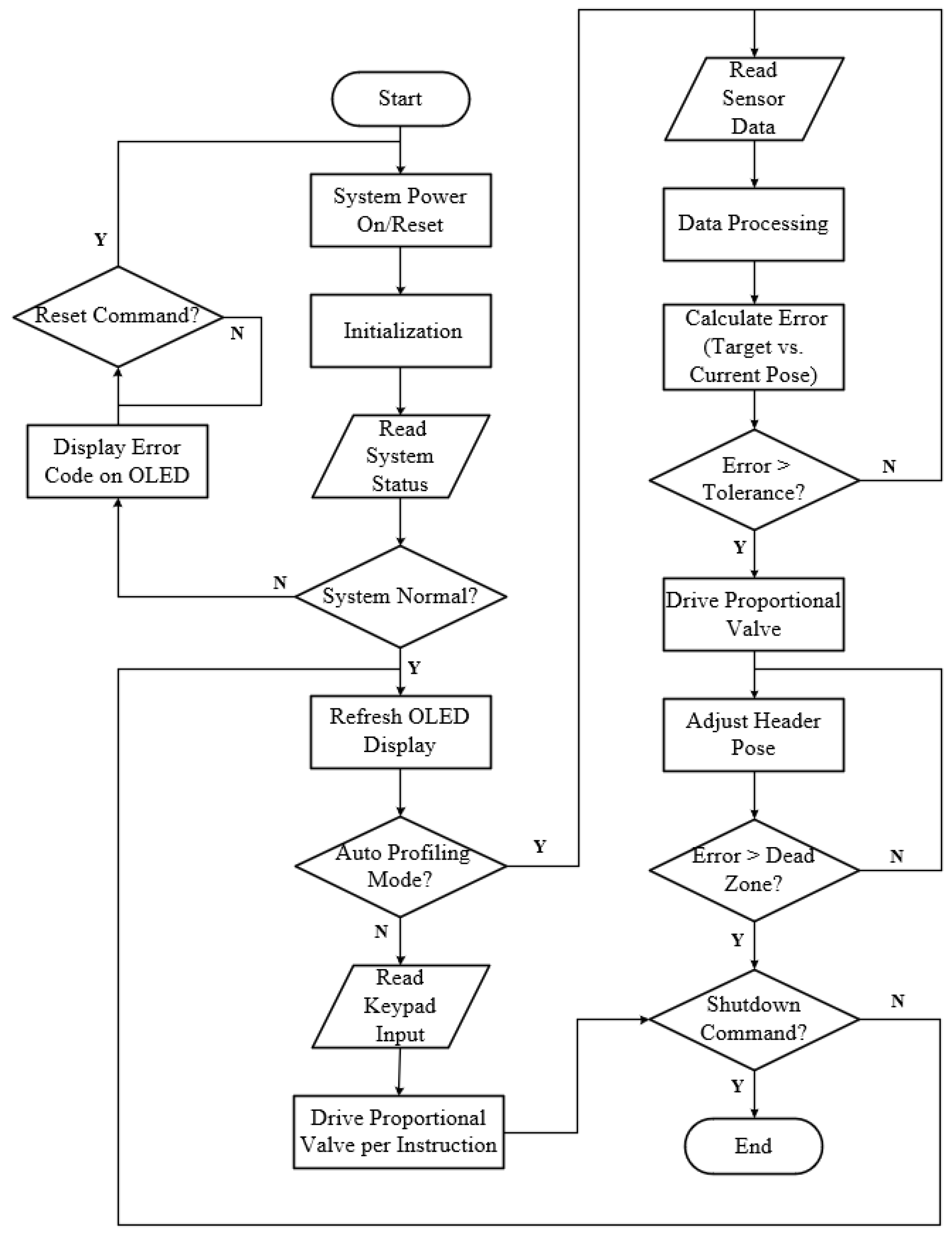
The decision layer is implemented based on the STM32F103C8T6 microcontroller (72 MHz main frequency, integrated 12-bit ADC, multiple serial ports). The integrated main control circuit is shown in Figure 12, and the control flow is shown in Figure 13. The controller collects sensor data in real time, calculates the deviation and deviation change rate between the current header height, pitch angle, roll angle, and the target values (stubble height 150 mm, pitch angle 0 ° , roll angle 0 ° ). It uses a fuzzy PID control algorithm to adjust PID parameters online and generate control commands. The fuzzy controller takes deviation e and deviation change rate ec as inputs and outputs the PID parameter corrections Δ K p , Δ K i , Δ K d . The fuzzy subsets are divided into seven levels (NB, NM, NS, ZO, PS, PM, PB), and the membership functions are triangular. A fuzzy rule base (49 rules in total) was constructed based on operational experience in hilly terrain, as shown in Table 2.
The execution layer consists of three independently controlled electro-hydraulic proportional circuits. Control commands are sent via the RS485 serial port using the Modbus-RTU protocol to the QX-VO04 analog voltage output module (Qixin Electronics, Chengdu, China, 4 channels, 0–10 V output), which drives the VT-VSPA1 (Bosch Rexroth, Lohr am Main, Germany) proportional amplifier. The amplifier outputs ± 10 mA bipolar current to control the 4WRA10 electro-hydraulic proportional directional valve (Huade Hydraulic, Beijing, China; rated flow 60 L/min, response time 0.02 s), thereby regulating the flow and direction of hydraulic oil to the cylinders. The pitch adjustment uses two symmetrically arranged hydraulic cylinders, synchronized by a flow divider-combiner valve; the roll and height adjustments are each driven by a single hydraulic cylinder. The hydraulic cylinder displacement is fed back to the controller via a built-in magnetostrictive displacement sensor, forming a position closed loop. The measured total system response delay is approximately 120 ms, which meets the real-time control requirements at operating speeds of 0.8–1.2 m/s and can effectively handle terrain undulations in hilly areas.
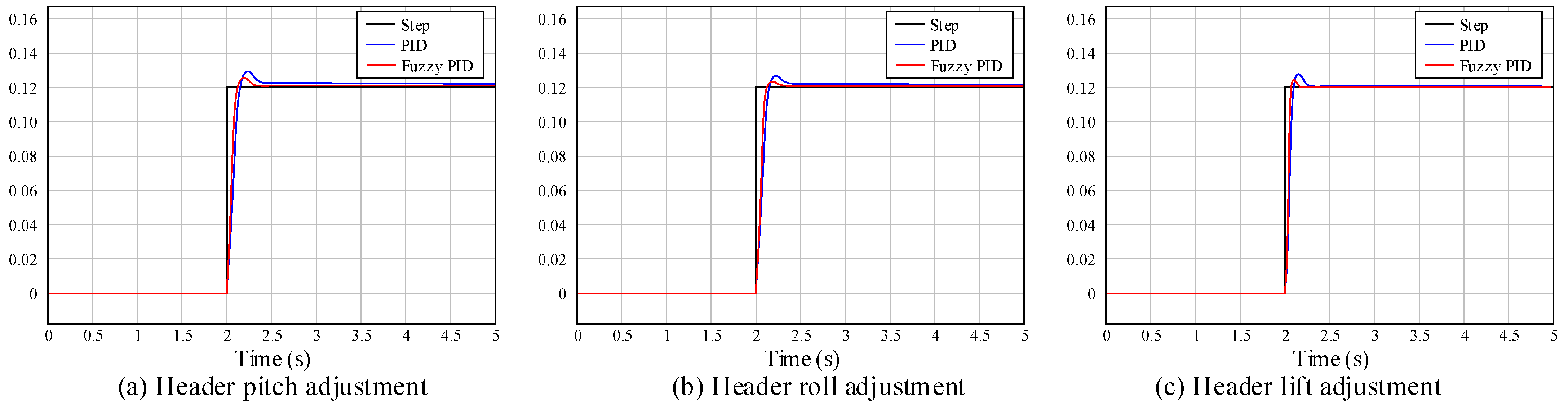
To verify the performance of the fuzzy PID controller, a comparative simulation model of traditional PID and fuzzy PID was built in Simulink based on the hydraulic system transfer function model established in Section 3.1.3. The controlled object transfer function consists of the amplifier-proportional valve section and the valve-controlled hydraulic cylinder section in series. The specific parameters were calculated based on the hydraulic cylinder selection results (Table 1), proportional valve characteristics, and hydraulic oil properties. The simulation input was a 0.12 m step displacement signal, which compares the response characteristics of the two control strategies. The results are shown in Figure 14. The simulation indicates that under traditional PID control, the overshoot for the pitch, roll, and height channels is 8.3%, 3.3%, and 10.0%, respectively, with a settling time of about 3 seconds. In contrast, fuzzy PID reduces the overshoot to 4.2%, 1.7%, and 4.2%, respectively, shortens the settling time by more than 30%, and achieves zero steady-state error. By adaptively adjusting parameters online, fuzzy PID effectively suppresses the overshoot and oscillation caused by the nonlinearity and time-varying characteristics of the hydraulic system, providing a reliable control parameter basis for subsequent field trials.

4. ADAMS Simulation and Analysis of the Header

4.1. Simulation Model Construction and Operating Condition Definition

After completing detailed 3D modeling of the header mechanism in SolidWorks and assigning mass attributes and performing interference checks for each moving part, the model was exported in x_t format and imported into ADAMS 2022 [29,30]. Based on the actual mechanical connection between components, corresponding joints were added: translational joints at the vertical guide rails, revolute joints at the pitch and roll angle adjustment pivot points, and spherical joints at both ends of each hydraulic cylinder, as shown in Figure 15. For direct comparison, a two-DOF header model, generated by locking the pitch angle adjustment’s revolute joint, was also created.
Two types of road models were set up in the simulation to comprehensively verify the header’s profiling performance:
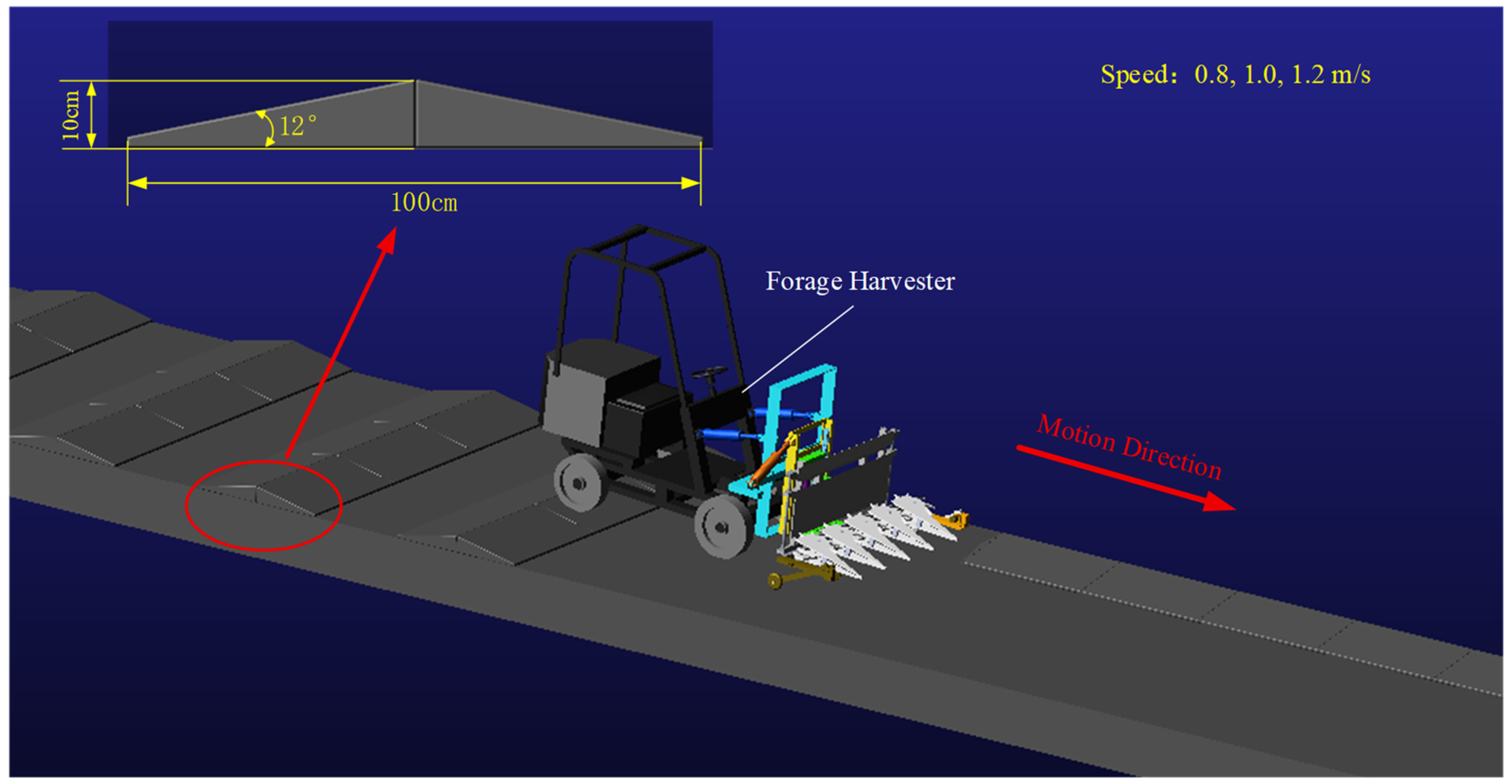
(1) Continuous undulating section: Used for header dynamics simulation in Section 4.2 to verify the dynamic response characteristics of the mechanism at different forward speeds. This road consists of a horizontal base surface and a series of ramps. The ramp height is approximately 10 cm, and the bottom length is approximately 100 cm. The angle between the ramp section and the horizontal plane is approximately 12°, covering the typical slope range of hilly terrain, effectively simulating the characteristics of continuous surface undulations in the field.
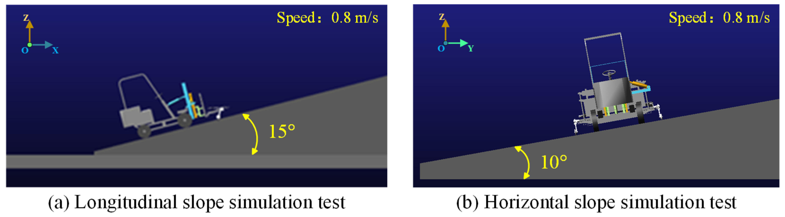
(2) Typical slope conditions: Used for profiling performance comparison under different slope conditions in Section 4.3, including a 15° longitudinal slope and a 10° transverse slope. The 15° longitudinal slope reaches the upper limit of the pitch adjustment design range, used to test the compensation capability and operational limits of the pitch degree of freedom under the most unfavorable forward slope. The 10° transverse slope is a typical value for lateral tilt terrain commonly encountered in hilly-area operations and is used to evaluate lateral leveling performance. In the simulation, the target stubble height of the header was set to 150 mm.
The slopes and undulation parameters of the above roads cover the typical range of 8–15° for hilly terrain, effectively testing the profiling performance of the header under multiple conditions. It should be noted that to simplify the model and improve computational efficiency, the simulation road uses regular geometric shapes and does not fully replicate the randomness and soil compressibility characteristics of real hilly terrain, which may lead to some deviations between simulation results and field trials.

4.2. Dynamics Simulation of Header

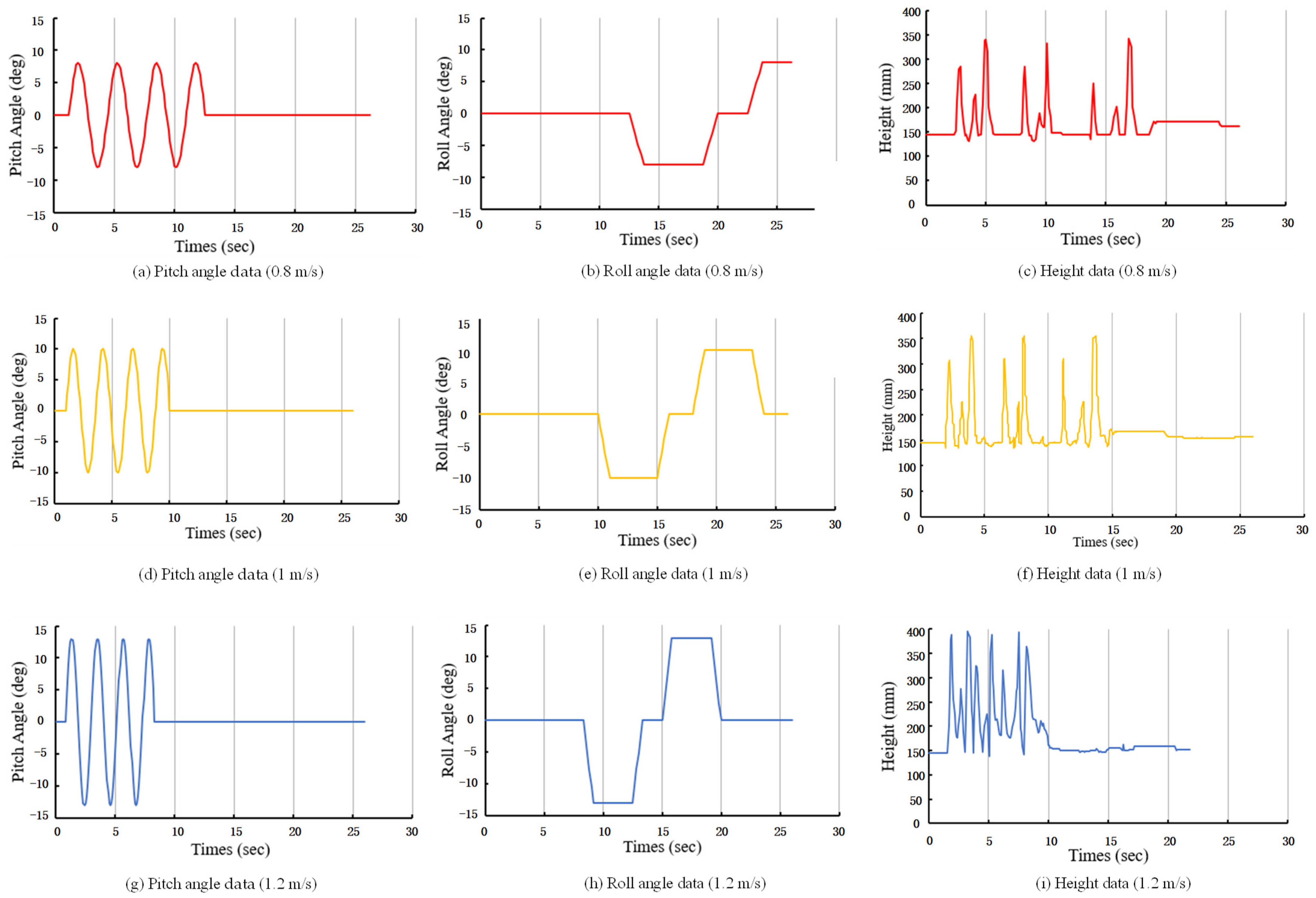
To verify the correctness of the header model construction and its kinematic performance, the header was controlled to travel on the road constructed in Section 4.1 at three forward speeds: 0.8 m/s, 1.0 m/s, and 1.2 m/s, and the three-DOF header was tested in simulation, as shown in Figure 16. The simulation duration was set to 26 s with a step size of 0.1. The center of mass of the header was used as the measurement marker point. The resulting curves of pitch angle, roll angle, and ground clearance are shown in Figure 17.
A comprehensive analysis of the dynamic simulation results of the header at three forward speeds of 0.8 m/s, 1.0 m/s, and 1.2 m/s was conducted, and each degree of freedom exhibited a dynamic response with distinct characteristics and mutual decoupling. The pitch angle variations exhibit continuous and symmetrical periodic oscillations. At the three speeds, the oscillation amplitudes are approximately ±8°, ±10°, and ±13°, respectively. Meanwhile, the period decreases from 2.5 s to 1.5 s with increasing speed, indicating that the pitch of the header has excellent dynamic tracking capability and speed adaptability. The roll angle variation curve exhibits a step-rectangular waveform, showing that the header can reach amplitudes of approximately ±8°, ±10°, and ±13°, respectively, through stepwise adjustment at three speeds. The adjustment initiation time advances with increasing speed, while the slope of the ramp section increases accordingly. This indicates that the dynamic response of the roll adjustment is enhanced as speed increases, enabling it to adapt to the discontinuous lateral slope changes commonly found in hilly terrain and to maintain a stable attitude after reaching the target. The height data curve exhibits an initial stability pattern, followed by a jump and subsequent gradual stabilization. The initial height of the header’s center of mass is 145 mm, peaking from 342.64 mm at 0.8 m/s to 387.64 mm at 1.2 m/s. As speed increases, the curve gradually exhibits a multi-peak oscillation trend, indicating that the height adjustment mechanism can effectively cope with road surface undulations. However, this also reveals the system’s dynamic characteristics: heightened inertial effects and relatively insufficient damping with increasing speed.
As the operating speed increases, the system’s dynamic response generally exhibits a trend of increased amplitude and accelerated response. At the same time, the inertial effect becomes more prominent, especially in the height adjustment, which manifests as a more complex damping oscillation process. Overall, the simulation results validate the effectiveness of the three-DOF mechanism’s motion decoupling design. Each module can independently and coordinately adapt to terrain changes, maintaining good speed tracking and dynamic stability. This analysis provides a clear basis for subsequent optimization of control parameters for different operating speeds to balance response speed and stability.

4.3. Comparison of Profiling Performance Under Different Slope Conditions

To comprehensively demonstrate the core role of the newly added pitch angle adjustment degree of freedom in dealing with the forward slopes and to examine the working effect of the mechanism on the lateral slopes, comparative simulations were conducted under the working conditions of a longitudinal slope of 15° and a lateral slope of 10°. The simulation scenario is illustrated in Figure 18. The three-DOF header model validated in Section 4.2 served as the experimental group. A two-DOF header model with only height and roll angle adjustment functions was generated by locking its pitch angle adjustment’s revolute joints as the control group. Both models traversed on the slope at the same speed of 0.8 m/s, and the comparison results for their stubble height tracking and attitude response are shown in Figure 19.
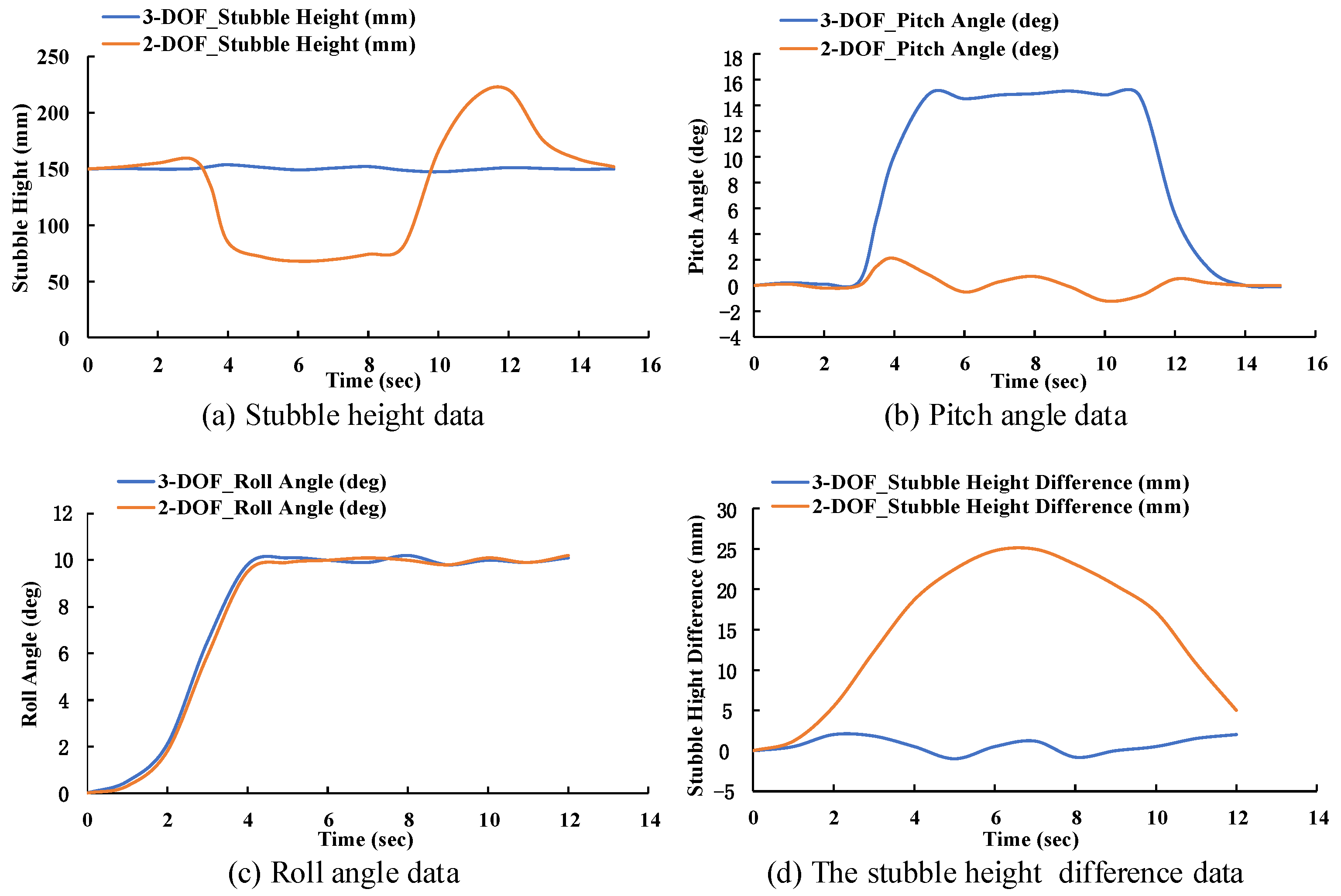
As shown in Figure 19a of the stubble height curve, the three-DOF header maintains the cutting blade plane parallel to the slope through active adjustment of the pitch angle adjustment hydraulic cylinder, and the stubble height is stabilized at around the set value of 150 mm, with a maximum deviation of ≤18 mm and a root mean square error (RMSE) of 4.2 mm. In contrast, the two-DOF header, lacking pitch compensation, experienced drastic fluctuations in stubble height, resulting in a sharp increase in RMSE to 42.7 mm and severe deterioration in harvest quality. The attitude angle curve in Figure 19b further reveals the underlying mechanism: the pitch angle of the three-DOF header can be quickly adjusted to 14.8° within 1 second and stably track the slope surface, with a dynamic error of less than 0.3°. In contrast, the pitch angle of the two-DOF header always passively fluctuates slightly around 0°. This comparison directly confirms that the lack of pitch angle adjustment is the fundamental cause of the traditional two-DOF header’s poor adaptability on longitudinal slopes and the serious unevenness of stubble height. The pitch angle adjustment mechanism introduced in this study effectively resolves this issue.
As shown in Figure 19c, both models achieve rotation around the Y-axis by adjusting the roll angle, eventually stabilizing at about 10°, indicating that both can level laterally. However, the stubble height difference curve in Figure 19d reveals a critical distinction: benefiting from the decoupling design among the three degrees of freedom, the experimental group rapidly eliminates and maintains the height difference between the left and right sides of the header within 5 mm during the leveling process through the independent compensation of the height adjustment mechanism. In contrast, the control group experienced undesirable overall height shifts during roll angle adjustment due to the inherent motion coupling, resulting in persistent height differences between the left and right sides with a maximum deviation of 25 mm. These results demonstrate that the decoupled design of the three-DOF header not only provides longitudinal pitch capability but also maintains superior consistency in the cutting plane during lateral leveling, overcoming the side effects of coupling adjustment inherent in two-DOF structures.

5. Field Trials and Analysis

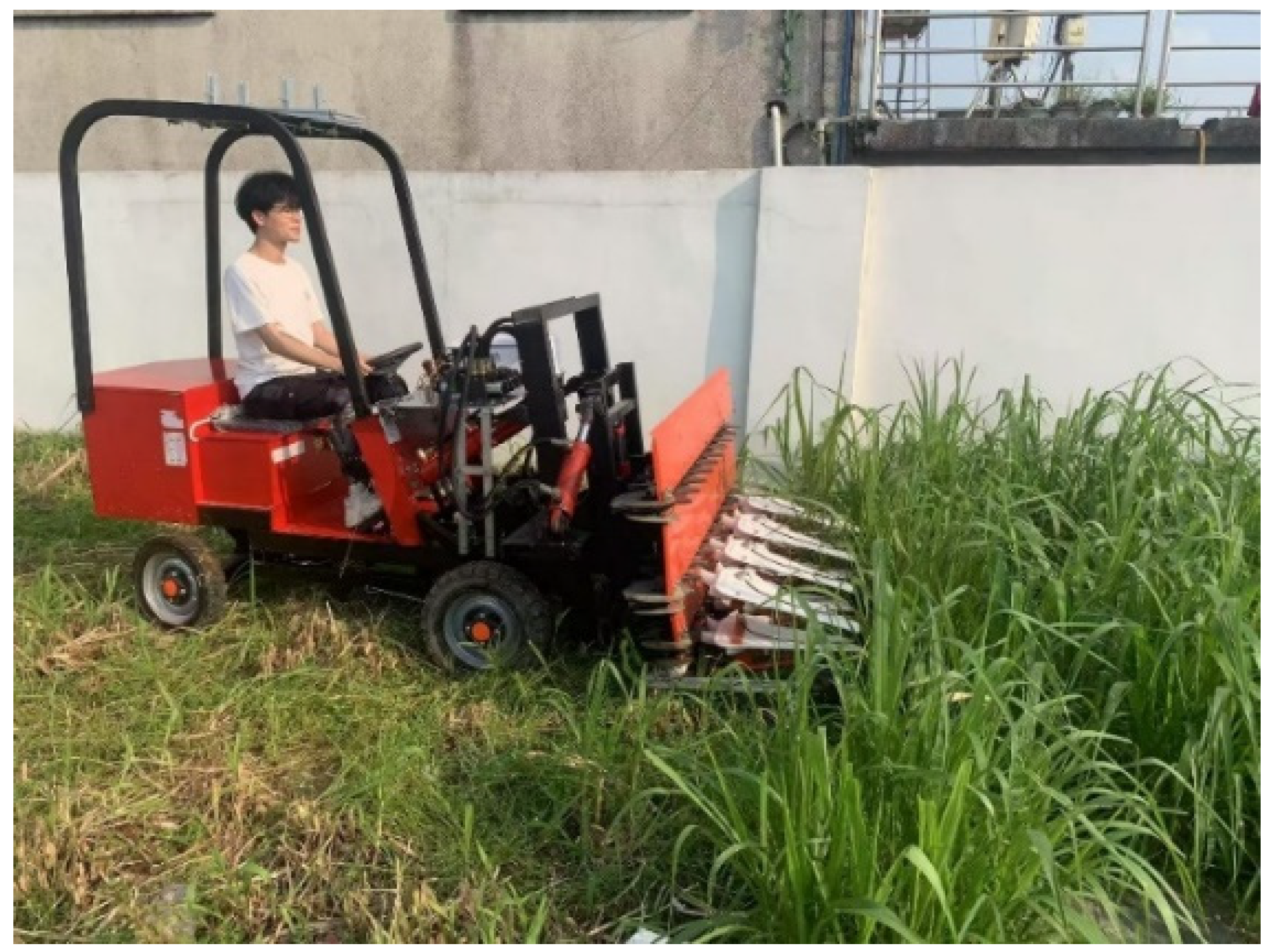
In August 2025, based on the results of kinematic and dynamic model optimization, a prototype of the three-DOF profiling header was manufactured, and field trials were conducted on a real hilly pasture to verify the header’s ability to meet design specifications and its operational effectiveness. The trial site was the Qilinnan Pasture Experimental Base of South China Agricultural University, featuring typical hilly terrain with gentle slopes. The test subject was young Pennisetum purpureum, which was in the vegetative growth stage during the trial. The planting row spacing was 20 cm, the average plant height was 45 cm (standard deviation 5.2 cm), the stem diameter was 2.5–3.5 mm, and the fresh grass yield was approximately 2200 kg/mu [31]. The lodging angle was measured before the test, with an average lodging angle of 6.5°, indicating no significant lodging. The soil type was sandy loam, and measurements showed a moisture content of 18.5% in the 0–10 cm soil layer, with a firmness of 0.8–1.2 MPa. Figure 20 shows the prototype being tested on the selected terrain.
Prior to testing, the ground surface flatness was measured according to the national standard. During testing, in accordance with national standard and the relevant methods in the General Provisions on the Test Conditions of Agricultural Machinery, a test area with a length of 30 m and a width equal to the cutting width was delineated in the harvested plot, with a 10 m preparatory area set up before and after the test area. To comprehensively evaluate the profiling performance, a multi-sensor synchronous acquisition scheme was adopted: a high-precision IMU sensor was installed at the center of mass of the header to capture pitch and roll angles in real time at a sampling frequency of 100 Hertz; a laser rangefinder sensor was installed below the front of the header to measure the vertical distance from the lowest point of the cutter to the ground surface in real time. The prototype performed straight-line operations within the test area at three preset speeds of 0.8 m/s, 1 m/s, and 1.2 m/s, recording sensor data throughout the process. Post-test, measurement sections were established every 5 m along the operation trajectory. At each section, three points were randomly selected for measuring the stubble height ( H i ) using a measuring tape. The average stubble height ( H j ) was calculated according to Formula (6):
H j = i = 1 n j H i n j
where n j is the total number of measurement points.
The stubble stability coefficient ( U j ) is used to comprehensively evaluate the uniformity of stubble height. Before calculation, the standard deviation ( S j ) and the coefficient of variation ( V j ) of the stubble height must be determined:
S j = i = 1 n j ( H i H j ) 2 n j 1
V j = S j H j × 100 %
U j = ( 1 V j ) × 100 %
A higher U j value indicates better stubble height consistency and superior profiling effect. The field trial results are shown in Table 3.
As shown in Table 3, the measured average stubble height values are slightly lower than the simulation predictions, with a consistent trend of increasing with speed. The measured stubble stability coefficient values are all higher than the predictions, indicating that the three-DOF header exhibits superior attitude maintenance and height tracking capabilities in actual terrain. IMU data show that the pitch and roll angles changed smoothly during operation. The measured maximum angle values approach, but remain slightly below, the design limit of ±15°, with the control error under 0.5° and no instances of cutter blades contacting the soil. Compared with the research team’s earlier test data using a two-DOF header on the same plot, while maintaining a similar stubble height (about 150 mm), the three-DOF header achieved an average increase of about 35% in the stubble stability coefficient and an effective increase of about 20% in operating speed. Field trial results verified the rationality of the three-DOF profiling header design and the reliability of the simulation model, indicating that this mechanism can significantly improve the stubble flatness and operational adaptability during forage harvesting in hilly and mountainous terrain.
To further verify the reliability of the simulation model, a quantitative comparison between simulation predictions and field trial measurements was conducted, with the results shown in Table 4.
As shown in Table 4, the measured average stubble height is slightly lower than the simulation prediction, with a relative error of −1%, indicating high accuracy of the height control model. The measured stability coefficients are higher than the simulation predictions, with a relative error of 3.6–4.6%, suggesting that the actual control system exhibits better regulation capability than the ideal model in complex terrain.
The measured maximum attitude angles differ significantly from the simulation predictions, primarily in two respects. (1) The measured pitch angles (14.1–14.5°) are substantially higher than the simulation predictions. This is because the simulation only incorporated regular trapezoidal bumps. Meanwhile, the actual terrain consists of long, continuous slopes, requiring the header to maintain a consistently higher pitch angle to track them. (2) The measured maximum attitude angles show a decreasing trend with increasing speed, while the simulation values show an increasing trend. Analysis suggests that the decreasing trend in measured values may be attributed to the control system’s safety strategy. At higher operating speeds, the controller actively limits the maximum adjustment amplitude to avoid shocks. However, the simulation model did not account for this control constraint, thus exhibiting an increasing trend dominated by inertial effects.
Possible reasons for the measured stubble height being slightly lower than the simulation include: (1) Field soil compaction under the harvester’s wheel tracks, causing the actual cutter position to be slightly lower than the theoretical height; (2) Small delays in the hydraulic system, causing the header response to lag behind terrain changes; (3) Small deformations upon contact between the profiling device and the soil were not considered in the simulation model. The above analysis indicates that the simulation model is reliable for trend prediction. However, the control parameters need further refinement based on measured data to better reflect the actual operational characteristics.

6. Discussion

The three-DOF profiling header designed in this study, by introducing a pitch adjustment degree of freedom and achieving mechanism decoupling, effectively overcomes the inherent limitations of traditional two-DOF headers in hilly terrain operations. Compared with existing research, this study demonstrates significant improvements in control accuracy and terrain adaptability.
In terms of control accuracy, Gong et al. [8] developed a header follow-up control system for sugarcane harvesters achieving stubble height deviation ≤20 mm; Long et al. [9] developed an adaptive header height adjustment system for rice-wheat combined harvesters with a control error ≤18 mm; Ji et al. [10] developed an automatic header height adjustment device for multi-crop harvesting with a control error ≤15 mm. The three-DOF header developed in this study achieves a stubble height control error ≤15 mm (maximum deviation 18 mm, RMSE 4.2 mm) on gentle slopes of 8–15°, which is comparable to, or slightly better than, the aforementioned studies. More importantly, this study maintains this level of accuracy under a 15° longitudinal slope condition, whereas none of the above studies verified longitudinal slope adaptability.
Regarding motion decoupling, although the study by Ni et al. [12] achieved adaptive header height adjustment, it did not address the coupling between roll and height adjustments. This study, through a guide-rail-and-slider mechanism for pure vertical lifting, combined with a series of spatial adjustment mechanisms, achieved independent adjustment of pitch, roll, and height. Both simulations and experiments confirmed that during lateral leveling, the three-DOF header can control the stubble height difference between the left and right sides to within 5 mm, whereas the two-DOF header can exhibit a height difference of up to 25 mm due to coupling effects.
This study still has certain limitations. First, the experiments primarily targeted typical gentle slopes of 8–15°, and the operational performance on steeper or more rugged terrain remains to be validated. Second, the simulation road used regular trapezoidal bumps. However, given the measured terrain’s dominant frequency characteristics, it did not fully replicate the randomness and soil compressibility of real terrain, resulting in a significant difference between the simulated and measured maximum attitude angles. Third, the current research focused on mechanism design and the implementation of basic profiling functions, without long-term durability testing. The reliability of the header under prolonged high-intensity operation needs further evaluation. Additionally, the measured stubble stability coefficients were higher than the simulation predictions. Analysis suggests this may be because the actual control system incorporated filtering for field high-frequency vibrations and adaptive gain adjustments during commissioning, resulting in better robustness than the ideal model. This finding suggests that appropriately introducing nonlinear control characteristics into the simulation model could help improve the consistency between simulation and measurement.

7. Conclusions

This study addresses the insufficient profiling capability of traditional headers in hilly and mountainous forage harvesting and designs a three-DOF profiling header, significantly improving operational quality and terrain adaptability on gentle slopes. The main findings are as follows:
(1)
A three-DOF profiling header configuration is proposed, featuring pitch angle, roll angle, and height adjustment. Through mechanism integration and geometric optimization, motion decoupling between degrees of freedom was achieved, fundamentally overcoming the inherent limitations of the two-DOF headers, such as poor longitudinal slope adaptability and strong coupling of adjustment motions.
(2)
A profiling control system based on a fuzzy PID control algorithm was designed, incorporating a hydraulic drive system, multi-source sensor fusion, and an STM32 main control unit. Hydraulic system simulation verified the linear controllability between the proportional valve input current and the hydraulic cylinder speed. The PID position closed-loop simulation showed a settling time of approximately 3 seconds and a steady-state error of less than 2 mm. Comparative simulation between fuzzy PID and traditional PID demonstrated that fuzzy PID reduced the overshoot of the three channels of pitch, roll, and height from 8.3%, 3.3%, and 10.0% to 4.2%, 1.7%, and 4.2%, respectively, while shortening the settling time by more than 30%.
(3)
The 3D model of the header was created in SolidWorks, followed by a multibody dynamics simulation in ADAMS. The simulation results demonstrate that on hilly terrain with gentle slopes ranging from 8° to 15°, the stubble height control error is within 10%, and the pitch and roll angle adjustment errors are below 0.5°, which verifies its dynamic response performance and decoupling effect.
(4)
Field trials demonstrated that, compared to the traditional two-DOF headers, the three-DOF headers improve the stability of the stubble height by about 35%, reduce the missed-cutting rate by about 5%, and improve operating efficiency by about 15% under identical operating conditions. Moreover, no instances of the cutting blade contacting the soil occurred, confirming the rationality and practicality of the mechanism design.
Although this study has achieved phased results in the control system of the three-DOF profiling header, several directions warrant further exploration. Subsequent research can be optimized and expanded from the following two aspects. In terrain perception, it is planned to introduce sensing elements such as LiDAR and binocular vision to construct a 3D reconstruction and advanced prediction model of the field terrain, enabling feedforward control for terrain changes and improving the system’s response speed and tracking accuracy for abrupt terrain changes. In terms of intelligent integration, the application of this three-DOF profiling header to unmanned harvesting robot platforms will be explored, combined with RTK-GNSS and SLAM navigation technologies, to achieve all-weather, unmanned, high-precision forage harvesting operations in hilly terrain, providing key technical support for smart agriculture.

Author Contributions

Conceptualization, Z.Z. and Y.X.; methodology, Y.X.; software, W.Z.; validation, Y.X., W.Z., and Y.L.; formal analysis, S.S.; investigation, Y.X.; resources, Y.L.; data curation, Y.X. and Y.L.; writing—original draft preparation, Z.Z., Y.X., and Y.L.; writing—review and editing, Y.X. and Y.L.; visualization, Y.X. and S.S.; supervision, Z.Z.; project administration, Z.Z.; funding acquisition, Z.Z. All authors have read and agreed to the published version of the manuscript.

Funding

The authors would like to acknowledge support for this study from the National Key R&D Program of China (Grant No. 2022YDF2001901-01).

Institutional Review Board Statement

Not applicable.

Informed Consent Statement

Not applicable.

Data Availability Statement

The datasets presented in this study are available from the corresponding author on reasonable request.

Acknowledgments

The authors gratefully acknowledge the editors and anonymous reviewers for their constructive comments on our manuscript.

Conflicts of Interest

The authors declare no conflicts of interest.

References

  1. Li, Y.; Zhang, S.; Pang, D. Current Status and Development Trends of Forage Harvesting Machinery in China. South. Agric. Mach. 2019, 50, 28. [Google Scholar]
  2. Liu, J. Mechanized Techniques for Forage Planting and Production. Agric. Eng. 2020, 10, 21–23. [Google Scholar]
  3. Lu, L. Agricultural Terminology; Science Press: Beijing, China, 1993. [Google Scholar]
  4. Sun, J.; Liu, Z.; Yang, F.; Sun, Q.; Liu, Q.; Luo, P. A Review of Key Technologies for Agricultural Equipment and Slope Operations in Hilly and Mountainous Areas. Trans. Chin. Soc. Agric. Mach. 2023, 54, 1–18. [Google Scholar]
  5. Luo, X. Reflections on Developing Agricultural Mechanization in Hilly and Mountainous Areas. Agric. Mach. Technol. Ext. 2011, 20, 17–20. [Google Scholar] [CrossRef]
  6. Li, H. Current Status of Intelligent Agricultural Machinery Development at Home and Abroad. Farmer’s Advis. 2020, 06, 93. [Google Scholar]
  7. Chen, Y.; Tian, F.; Yan, Y.; Song, Z.; Li, F.; Chen, W. Current Status and Trends in Domestic and International Forage Harvesting Machinery Development. Chin. J. Agric. Mach. Chem. 2018, 39, 1–5. [Google Scholar] [CrossRef]
  8. Gong, Y.; Jin, Z.; Bai, X.; Wang, S.; Wu, L.; Huang, W. Design and testing of a follow-up control system for sugarcane harvester headers. Trans. Chin. Soc. Agric. Mach. 2023, 54, 119–128+138. [Google Scholar]
  9. Long, Z.; Xiang, Y.; Li, Y.; Hu, Z.; Liu, A.; Dai, X. Adaptive height adjustment system for combine headers based on tilt sensors. J. Chin. Agric. Univ. 2021, 26, 200–208. [Google Scholar]
  10. Ji, K.; Li, Y.; Li, G.; Wang, X.; Wang, H. Design and Testing of an Automatic Height Adjustment Device for Combine Harvester Heads. Res. Agric. Mech. 2023, 45, 85–89+94. [Google Scholar] [CrossRef]
  11. Zhao, L.; Jiao, S.; Wang, C.; Zhang, J. Research on Terrain Sensing Method and Model Prediction for Height Adjustment of Sugarcane Harvester Base Cutter. Wirel. Commun. Mob. Comput. 2022, 2022, 1–15. [Google Scholar] [CrossRef]
  12. Ni, Y.; Jin, C.; Chen, M.; Yuan, W.; Qian, Z.; Yang, T.; Cai, Z. Computational model and adjustment system of header height of soybean harvesters based on soil-machine system. Comput. Electron. Agric. 2021, 183, 105907. [Google Scholar] [CrossRef]
  13. Zhu, L.; Wang, D.; You, Y.; Wu, B.; Ma, W.; Xun, X. Design and Testing of a Tracked Inter-row Grass Strip Harvester. Trans. Chin. Soc. Agric. Mach. 2021, 52, 126–133. [Google Scholar]
  14. Liu, W.; Zeng, S.; Chen, X. Design and Experiment of Adaptive Profiling Header Based on Multi-Body Dynamics–Discrete Element Method Coupling. Agriculture 2024, 14, 105. [Google Scholar] [CrossRef]
  15. Jin, C.; Liu, G.; Ni, Y.; Yang, T.; Wang, T.; Qi, Y. Design and Testing of a Contour-Following Mechanism for Combine Harvester Cutter Bars Based on MBD-DEM Coupling. Trans. Chin. Soc. Agric. Eng. 2022, 38, 1–10. [Google Scholar]
  16. Geng, A.; Zhang, M.; Zhang, J.; Zhang, Z.; Gao, A.; Zheng, J. Design and Testing of an Automatic Height Control System for Corn Combine Heads. Trans. Chin. Soc. Agric. Mach. 2020, 51, 118–125. [Google Scholar]
  17. Zhu, L.; You, Y.; Wang, D.; Zhang, N.; Ma, W.; Liu, Z. Optimization of the folding mechanism and research on the hydraulic contouring system for suspended mowers. Trans. Chin. Soc. Agric. Mach. 2022, 53, 122–130. [Google Scholar]
  18. Tan, H.; Wang, G.; Zhou, S.; Jia, H.; Qu, M.; Xiang, M.; Zou, Z. Design and Experiment of Header Height Adaptive Adjustment System for Maize (Zea mays L.) Harvester. Sustainability 2023, 15, 14137. [Google Scholar] [CrossRef]
  19. Mou, X.; Yang, F.; Duan, L.; Liu, Z.; Song, Z.; Li, Z.; Guan, S. Current status and development trends of key technologies for tractor leveling and rollover prevention in hilly and mountainous areas. Smart Agric. 2024, 6, 1–16. [Google Scholar]
  20. Zhao, R.; Hu, L.; Luo, X.; Zhang, W.; Chen, G.; Huang, H.; Liu, H. Method for estimating vertical kinematic states of working implements based on laser receivers and accelerometers. Biosyst. Eng. 2021, 203, 9–21. [Google Scholar] [CrossRef]
  21. Xu, Z. Handbook of Forage Crops in China; Chemical Industry Press: Beijing, China, 2004. [Google Scholar]
  22. China Academy of Agricultural Mechanization Sciences. Agricultural Machinery Design Manual Manual (Lower Volume); China Agricultural Science and Technology Press: Beijing, China, 2007; pp. 877–1028. ISBN 978-7-80233-335-2. [Google Scholar]
  23. Xin, Z.; Jiang, Q.B.; Zhu, Z.X.; Shao, M.X. Design and optimization of a new terrain-adaptive hitch mechanism for hilly tractors. Int. J. Agric. Biol. Eng. 2023, 16, 134–144. [Google Scholar] [CrossRef]
  24. Ding, Z.; Ma, S.; Zhang, X.; Liang, W.; Li, L.; Su, C. Ultrasonic Sensor-Based Base cutter Height Control System of Sugarcane Harvester. Sugar Tech. 2023, 25, 453–459. [Google Scholar] [CrossRef]
  25. Wang, S.; Li, B.; Chen, S.; Tang, Z.; Zhou, W.; Guo, X. Design and performance test of soybean profiling header suitable for harvesting bottom pods on film. Agriculture 2024, 14, 1058. [Google Scholar] [CrossRef]
  26. Ling, X.; Zhao, C. Design and Simulation of a Contouring Device for Small-Scale Grass Cutting and Crushing Machines. Chin. J. Agric. Mach. Chem. 2020, 41, 63–67+74. [Google Scholar] [CrossRef]
  27. Dettù, F.; Corno, M.; D’Ambrosio, D.; Acquistapace, A.; Taroni, F.; Savaresi, S. Modeling, control design and experimental automatic calibration of a leveling system for combine harvesters. Control Eng. Pract. 2023, 132, 105411. [Google Scholar] [CrossRef]
  28. Zhou, M.; Xia, J.; Zhang, S.; Hu, M.; Liu, Z.; Liu, G.; Luo, C. Development of a depth control system based on variable-gain single-neuron PID for rotary burying of stubbles. Agriculture 2021, 12, 30. [Google Scholar] [CrossRef]
  29. Hao, Z.; Wu, Z.; Li, Y.; Wei, D.; Zhou, J.; Li, S. Design and Testing of a Cutting Head for Industrial Hemp Harvesters. Trans. Chin. Soc. Agric. Mach. 2024, 55, 112–121. [Google Scholar]
  30. Chen, K.; Tian, G.; Gu, B.; Liu, Y.; Wei, J. Design and simulation of the front frame for an orchard obstacle-avoidance mower. Jiangsu Agric. Sci. 2020, 48, 226–232. [Google Scholar] [CrossRef]
  31. Liu, Z.; Yang, C.; Yang, N.; Cui, Y.; Liu, Z. Effects of Planting Density and Topdressing Nitrogen Fertilizer on the Forage Production Performance of Pennisetum Species. Mod. Ani. Husb. Vet. Med. 2025, 12, 32–36. [Google Scholar]
Figure 1. Three-dimensional model of the three-DOF adjustable header. Note: 1. Vehicle 2. Header reel; 3. Profiling device; 4. Cutting blade; 5. Front baffle; 6. Roll angle adjustment hydraulic cylinder; 7. Gantry frame; 8. Pitch angle adjustment hydraulic cylinder; 9. Guide rail; 10. Adjustable height frame; 11. Height adjustment hydraulic cylinder; 12. Slider; 13. Integral thrust bearing; 14. Rolling frame.
Agriengineering 08 00145 g001
Figure 2. Diagrams of the core adjustment mechanism of the header.
Agriengineering 08 00145 g002
Figure 3. Flowchart of the working principle.
Agriengineering 08 00145 g003
Figure 4. Hydraulic control schematic diagram of the header. Note: 1 and 2: Pitch drive hydraulic cylinder; 3: Roll drive hydraulic cylinder; 4: Height drive hydraulic cylinder; 5 and 6: Flow divider-combiner valves; 7, 8, and 9: Three-position four-way electro-hydraulic proportional directional valves; 10: Pressure gauge; 11: Accumulator; 12: Fixed displacement hydraulic pump; 13: Relief valve; 14: Suction filter.
Agriengineering 08 00145 g004
Figure 5. Force analysis diagrams of the hydraulic cylinder.
Agriengineering 08 00145 g005
Figure 6. Force diagram of the pitch angle adjustment hydraulic cylinder.
Agriengineering 08 00145 g006
Figure 7. Force diagram of the roll angle adjustment hydraulic cylinder.
Agriengineering 08 00145 g007
Figure 8. AMEsim hydraulic system simulation model.
Agriengineering 08 00145 g008
Figure 9. Response curves of hydraulic cylinder speed and displacement under different input currents.
Agriengineering 08 00145 g009
Figure 10. Speed switching response curve.
Agriengineering 08 00145 g010
Figure 11. Terrain perception scheme.
Agriengineering 08 00145 g011
Figure 12. The physical diagram of the integrated main control circuit.
Agriengineering 08 00145 g012
Figure 13. Control flow chart.
Agriengineering 08 00145 g013
Figure 14. Simulation of step responses for traditional PID and fuzzy PID.
Agriengineering 08 00145 g014
Figure 15. Definition of key joints.
Agriengineering 08 00145 g015
Figure 16. Simulation test diagram of the virtual model.
Agriengineering 08 00145 g016
Figure 17. Simulation results at speeds of 0.8 m/s, 1.0 m/s, and 1.2 m/s.
Agriengineering 08 00145 g017
Figure 18. Simulation test diagrams of different slopes.
Agriengineering 08 00145 g018
Figure 19. The simulation results for different DOF on longitudinal and transverse slopes. Note: (a,b) are the results on the longitudinal slope; (c,d) are the results on the transverse slope.
Agriengineering 08 00145 g019
Figure 20. The three-DOF header in field operation.
Agriengineering 08 00145 g020
Table 1. Summary of design parameters for three types of hydraulic cylinders.
Types of Hydraulic CylinderPressure Rating (MPa) D (mm) d (mm)Stroke (mm)
Pitch angle adjustment≤166335150
Roll angle adjustment≤166335150
Height adjustment≤165028250
Table 2. Fuzzy rule table.
Δ K p / Δ K i Δ K d ec
NBNMNSZOPSPMPB
eNBPB/NB/PSPB/NB/NSPM/NM/NBPM/NM/NBPS/NS/NBZO/ZO/NMZO/ZO/ZO
NMPB/NB/PSPB/NB/NSPM/NM/NBPS/NS/NMPS/NS/NMZO/ZO/NSNS/ZO/ZO
NSPM/NB/ZOPM/NM/NSPM/NS/NMPS/NS/NMZO/ZO/NSNS/PS/NSNS/PS/ZO
ZOPM/NM/ZOPM/NM/NSPS/NS/NSZO/ZO/NSNS/PS/NSNM/PM/NSNM/PM/ZO
PSPS/NM/ZOPS/NS/ZOZO/ZO/ZONS/PS/ZONS/PS/ZONM/PM/ZONM/PB/ZO
PMPS/ZO/PBZO/ZO/PSNS/PS/PSNM/PS/PSNM/PM/PSNM/PB/PSNB/PB/PB
PBZO/ZO/PBZO/ZO/PMNM/PS/PMNM/PM/PMNM/PM/PSNB/PB/PSNB/PB/PB
Table 3. Performance comparison of 3-DOF and 2-DOF cutterbars in field tests.
Speed (m·s−1)3-DOF H j /mm2-DOF
H j /mm
3-DOF
U j /%
2-DOF
U j /%
3-DOF Maximum Pitch Angle/°3-DOF Maximum Roll Angle/°
0.8148.5195.385.262.814.514.3
1.0149.8202.786.561.314.314.1
1.2151.2211.487.958.914.113.9
Note: The data of the 2-DOF header comes from a comparative test conducted by the research group in August 2024 on the same experimental plot and under the same crop conditions (not published). The 2-DOF header only provides lifting and rolling adjustment, with the pitch angle locked at 0°. Simulation prediction values: H j : 149.8, 151.0, 152.3 mm; U j : 82.1, 83.5, 84.0%; Maximum Pitch Angle: 8°, 10°, 13°; Maximum Roll Angle: 8°, 10°, 13°.
Table 4. Comparison results of simulation and field trials.
IndicatorsSpeedSimulation Prediction ValuesMeasured
Values
Absolute
Error
Relative Error
H j 0.8 m/s149.8 mm148.5 mm−1.3 mm−0.87%
1.0 m/s151.0 mm149.8 mm−1.2 mm−0.79%
1.2 m/s152.3 mm151.2 mm−1.1 mm−0.72%
U j 0.8 m/s82.1%85.2%3.1%3.78%
1.0 m/s83.5%86.5%3.0%3.59%
1.2 m/s84.0%87.9%3.9%4.64%
Maximum Pitch
Angles
0.8 m/s8.0°14.5°6.5°81.25%
1.0 m/s10.0°14.3°4.3°43.00%
1.2 m/s13.0°14.1°1.1°8.46%
Disclaimer/Publisher’s Note: The statements, opinions and data contained in all publications are solely those of the individual author(s) and contributor(s) and not of MDPI and/or the editor(s). MDPI and/or the editor(s) disclaim responsibility for any injury to people or property resulting from any ideas, methods, instructions or products referred to in the content.