


Abstract
The aim of this study is to investigate the integration of Shape Memory Alloy (SMA) torque tubes into SmallSats’ thermal management systems to passively deploy radiator panels in an autonomous manner. Specific aspects of the investigation are related to material production, thermomechanical characterization, structural integration, and assessment of overall prototype functionalities. Implementation feasibility was evaluated through a 12U CubeSat test case. Starting with NiTi tubes ( at Ni.) intended for pseudoelastic applications, a combined aging and shape-setting heat treatment process was selected to achieve both SME characteristics and an S-shaped geometric configuration. Comprehensive material characterization was conducted using differential scanning calorimetry (DSC) and mechanical testing to evaluate post-treatment phase transformation temperatures (PTTs) and torsional load response. Experimental results demonstrated the actuator’s capacity to fully recover imposed rotations exceeding ° against resisting torques up to 0.1 Nm. Material cyclic stability analysis revealed rapid stabilization after four cycles, with maintained performance through 80 cycles. The experimental validation culminated in benchtop prototype testing, which achieved an ° deployment rotation, evidencing the viability of the proposed mechanism.
1. Introduction
Since the 1990s, a trend towards the miniaturization of satellites has been observed in the space sector [1]. This trend has been driven primarily by the revolution in the microelectronics industry, which has enabled the development of much smaller satellite systems, offering advantages such as shorter development times and cost savings [2,3]. More recently, small satellites (SmallSats) have been increasingly used to conduct space missions, as demonstrated by the Artemis-1 mission, which launched 13 CubeSats to conduct scientific experiments in deep space, and the development of the Starlink mega-constellation by SpaceX [4,5].
With the increasing demand for SmallSats, the performance of the components continues to increase, requiring more power for all functional subsystems (e.g., electric propulsion, higher power imaging payloads, or higher power communication payloads), consequently requiring improved thermal management systems (TMSs) [6].
Body-mounted radiators cannot cope with the thermal loads as their surface area is severely restricted. An ideal body-mounted radiator analysis was carried out by Hengelved et al. [7], revealing that the maximum dissipable power does not meet the requirements of the next generation of high-performance SmallSats. Larger and more efficient radiating surfaces are mandatory. The challenge is that the space for the payload in the launcher fairing is limited. Therefore, satellites with large appendages and a main body exceeding the available envelope are not allowed [8].
Deployable radiators may be a solution, as they are compactly packed before launch and can be deployed in large space configurations if required. According to Hengelved et al. [9], realistic deployable radiator designs ensure 220% more heat dissipation than state-of-the-art body-mounted radiators, thus offering the opportunity to increase the total possible bus power. With deployable radiators, a nominal 6U SmallSat can realistically dissipate about 200 W.
Deployable radiators face a significant challenge in transferring heat from the spacecraft body to the radiator with minimal temperature drop, as the hinges may create thermal choke points that limit dissipation efficiency. This is a critical issue particularly for SmallSats, as the density of the heat flow through the hinges is much higher. The heat dissipation density for a 12 kW GEO communication satellite is about 26.8 W/m (through the hinges), whereas it exceeds 193 W/m for a 500 W 12U CubeSat [10]. Innovative design solutions are therefore required.
Deployable radiators should be equipped with a simple, reliable, and non-energy-demanding driving system (i.e., a system actuating the deployment). Considerable progress has been made in the development of novel driving technologies to meet these requirements. Smart materials offer new opportunities in the design of deployable structures and actuation strategies. They reduce structural complexity, the number of components, and improve maneuverability and adaptability [11].
Shape Memory Alloys (SMAs) are one of the early examples of smart materials that are effectively utilized in smart driving systems for space deployable structures. SMAs are intermetallic compounds that exhibit unique behaviors such as pseudo-elasticity (PE) and one-way Shape-Memory Effect (SME). SME refers to the ability of the material to recover its original shape after mechanical deformation through a solid-state, diffusionless phase transformation caused by the imposition of a temperature field [12].
The SME makes Shape Memory Alloys ideal candidates for actuation in a wide range of advanced engineering applications, including those in the space sector [13,14,15,16,17,18,19]. In the context of deployable radiators, this property enables the development of structures capable of autonomously adapting their configurations to varying thermal conditions. Such an approach offers the potential for environmentally responsive and, in some cases, fully passive deployment mechanisms, thereby reducing the overall energy demands of the spacecraft’s thermal management system while maintaining reliability and simplicity of design [20].
Nagano et al. [21] developed and tested a reversible thermal panel (RTP), leveraging a single crystal Shape Memory Alloy (SCSMA) spring as an actuator for deployment. Thermal vacuum tests demonstrated the autonomous thermal control performance of the RTP, and analytical computations showcased the actual energy savings provided by the designed system in comparison with conventional radiators.
Bertagne et al. [22] proposed a novel concept of an adaptive morphing radiator. The proposed morphing design exploits the martensitic transformation of SMAs to passively reconfigure the radiator shape in order to comply with varying heat rejection requirements during the progress of the mission. Two proof-of-concept prototypes were developed, consisting of pre-curved laminates in which SMA wires in an X configuration were responsible for the morphing action due to temperature variation. Experimental tests demonstrated the feasibility of the proposed concept, and numerical simulations highlighted the high turndown ratios that the morphing radiator concept could offer.
Although the aforementioned studies have demonstrated the feasibility and effectiveness of SMA-based concepts for adaptive radiators, in most of these architectures, the SMA actuator is implemented as a distinct mechanical component, thermally coupled but not structurally integrated within the main thermal control system. This separation can increase design complexity and introduce additional interfaces between the mechanical and thermal domains, potentially limiting overall efficiency and compactness. Moreover, the actuator is generally heated through the surrounding structure rather than being in direct thermal contact with the primary heat-dissipation path. This suggests potential for improved thermal coupling and system integration.
Building upon these achievements, the present study proposes a novel concept of a deployable radiator that leverages a non-invasive and energy-efficient SMA-based driving system. The proposed solution involves integrating an SMA-based hinge, in the form of a small torque-tube, into a TMS pumped fluid loop (PFL) to passively control SmallSats’ deployable radiators. This integrated hinge serves the functions of thermal control branch and actuation method using a single element. The mechanism controlling the SMA activation relies on fluid flowing inside the tube undergoing temperature changes. Heat dissipation is achieved through the deployment of a radiative panel triggered by SME, induced by circulating fluid within the thermal control system. As a result, an autonomous and highly integrated actuation mechanism is achieved without relying on external energy sources, since the required energy for the phase transition of the SMA element is provided by the heat dissipation itself. The choke points in the hinge of the deployable radiator are not eliminated but rather exploited as a design advantage to feed the SMA.
Although SMAs have already been considered in the development of TMS for SmallSats, to the best of our knowledge, no study in the literature provides a comprehensive and systematic analysis of the aforementioned concept in all its fundamental aspects, from material production and thermomechanical characterization to structural integration and overall functional evaluation of the prototype. To this end, this work presents a practical application of the concept to a 12U CubeSat minisatellite. A preliminary and simplified investigation has been reported in [23,24]. The proposed design refers to a single deployable radiator, but it can be easily extended to accordion-like folded structures. The thermomechanical properties of SMA torque tubes, including cyclic stability, are investigated. A technological demonstrator is then designed, developed, and tested in a terrestrial environment to assess whether the proposed solution can be practically implemented.
2. Actuator Design
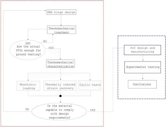
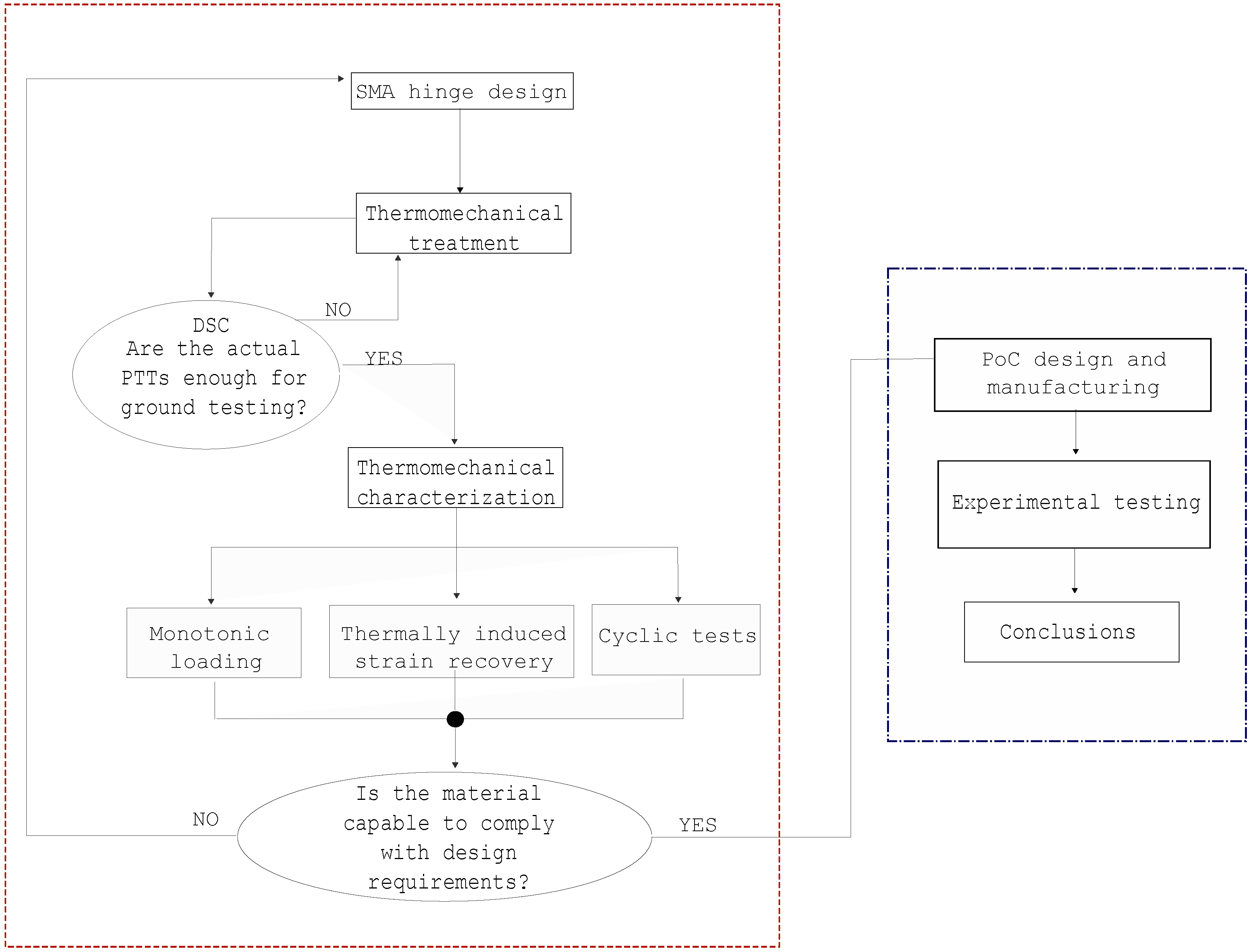
The methodology followed to develop the entire investigation is conceptually schematized in Figure 1.
Figure 1.
Logical diagram representing the methodology adopted to develop the investigation.
A case study is carried out on the deployment of a single radiator panel along the long side of a 12U CubeSat. The maximum available size for the SMA hinge is therefore 340.5 mm. Configurations in which the SMA hinge works in bending or torsion are considered and compared preliminarily.
2.1. Bending Hinge
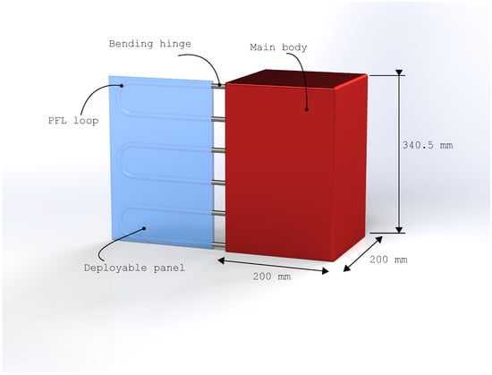
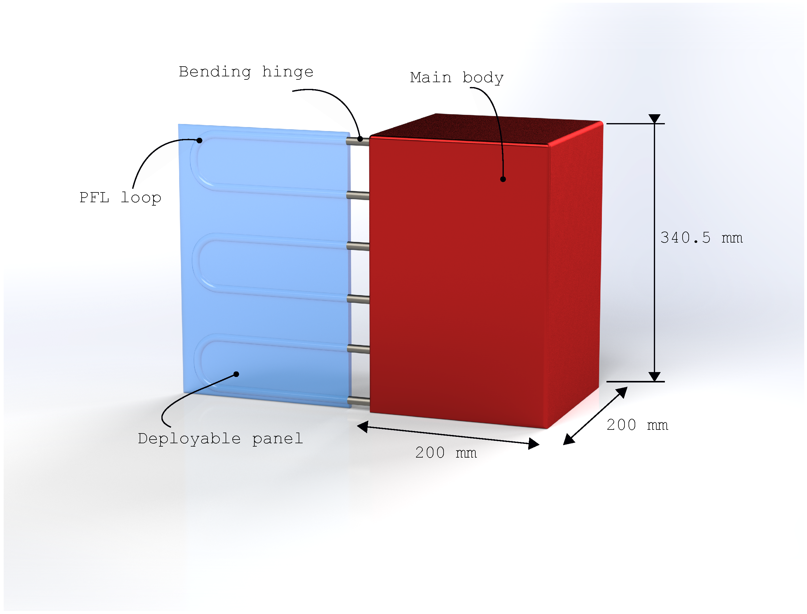
The SMA hinge consists of a series of tubes arranged in the corner between the main structure and the movable panel to be opened (Figure 2). Each tube is first annealed into a straight shape and then bent at a angle with a suitable radius of curvature prior to installation to prevent permanent plastic deformation. As movement takes place under minimal external load (in a low gravity environment, only frictional forces, if any, need to be considered), the only driving parameter is the bending strain, which remains the same for all tubes regardless of their number. The two ends of each tube are connected to the PFL circuits of the CubeSat and movable panel. When activated, each SMA tube undergoes free recovery at quasi-zero force and returns to its memorized straight configuration, causing the panel to deploy.
Figure 2.
Schematic representation of the bending hinge solution.
Preliminary design considerations can be made by neglecting geometrical and material non-linearities using a linear hyperelastic isotropic constitutive model in conjunction with beam theory. The small portion of the tube involved in the shape recovery process , the deflection angle , the bending radius , and the external radius of the tube can all be linked through the following equations:
where is the maximum strain value in the tube [25]. With a fixed radius, there are two competing parameters. Whereas the bending radius must be small in order to minimize the lateral extent of the actuator, the strain must not exceed the maximum transformation strain of the SMA used.
If repeated opening and closing cycles of the panel are also required, the system must be designed with an even lower value. The lower the transformation strain amplitudes, the lower the amount of plastic strains accumulated during thermally induced martensite phase transformation cycles, resulting in an improved actuator fatigue life [26]. For this reason, we limit the design of the actuator to a maximum allowable transformation strain .
Assuming an outer tube diameter of 3 mm, the bending radius becomes 60 mm, which can be accommodated in a sufficiently small space for the hinge. However, considering the linear dependence of the bending radius on the diameter of the tube, the space required for the hinge could become a remarkable issue if larger tubes are specified by the circuit design.
2.2. Torsional Hinge with Passive Segment
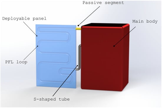
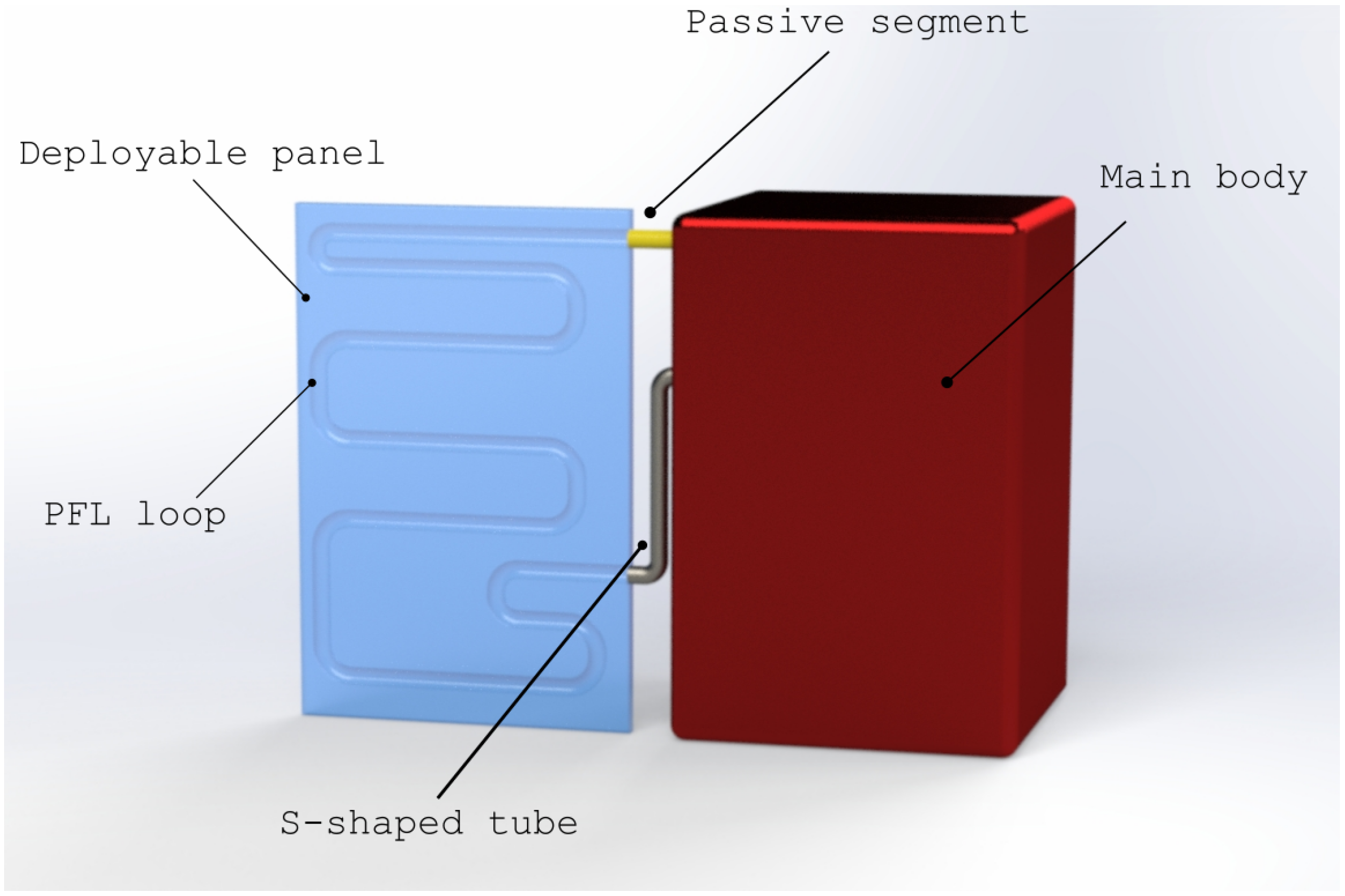
The SMA hinge is an integral part of the PFL circuit and consists of a single tube placed laterally between the main structure and the movable panel (i.e., along the hinge axis). An S-shape is proposed to prevent stresses on the tube from being transferred to the fittings, causing them to slip during actuation and reset. As the two shorter sides are not twisted and rotate rigidly, a firm connection with the circuit is maintained. The active length of the SMA tube is therefore only the straight middle section. A conceptual representation of the torsional hinge is depicted in Figure 3.
Figure 3.
Schematic representation of the S-shaped torsional hinge with passive segment.
The tube should be annealed in the flat S-shape and then twisted before installation (armed configuration) leveraging the shorter sides so that the total angle of rotation between the sections is . Upon activation, the imposed torsion is restored, forcing the panel to deploy. This configuration for the SMA hinge requires the presence of a flexible passive element to close the PFL. The tube’s output torque must exceed the resistance of both the rearming element and the flexible passive segment. The maximum engineering shear strain in the tube section can be computed as follows:
is the torsion angle and is the active length of the tube [27].
Assuming a maximum distance between tube inlet-outlet mm (which is compatible also with the short sides of the CubeSat) and a radius mm, the maximum engineering shear strain is , below the design limit.
This solution offers more design flexibility than the bending hinge. If the PFL hydraulics require larger or smaller diameters, it is possible to control the shear strain values by increasing or decreasing the parameter . For this reason, this solution is considered a reference for the development of the work. The proposed concept can be readily scaled to accordion-like folded configurations. In such architectures, the cumulative angular deformation required for full deployment would approximately double, resulting in an estimated strain increase of about . This value remains within a conservative range when compared to the established for the single-panel actuator, suggesting that the scalability of the proposed SMA-based hinge is feasible without imposing critical additional demands on material performance.
2.3. Resetting Strategies
In many space applications, a single deployment process may be sufficient. When the actuating element is based on Shape Memory Alloys (SMAs), the design can conveniently rely on the conventional one-way shape memory effect (OWSME). During ground integration, the actuator can be mechanically deformed to the desired pre-strain level so that, once in orbit, the selected thermal stimulus for the shape recovery ensures the deployment of the structure to the target configuration. The deployable structure then remains locked in this configuration for the entire operational lifetime of the spacecraft. This is because, in conventional one-way SMAs, after the initial recovery of the memorized shape by heating, neither subsequent cooling nor further heating can cause additional shape changes.
However, in the case of deployable radiators, the actuator may be required to perform its motion several times on demand. A resetting strategy is therefore necessary to rearm the actuator after each SME activation.
The simplest approach is to integrate a biasing element, such as a mechanical spring, within the actuation system. During deployment, the SMA actuator loads the spring elastically. When the operational environment drives the actuator back into the martensitic phase, the biasing force exerted by the spring induces detwinning in the SMA, thereby restoring the pre-strain and rearming the actuator for subsequent activation. The design of such a system must carefully balance the authority between the two elements. The recovery strain of the SMA must be sufficient to overcome the bias force during deployment to achieve the desired deployed configuration, whereas the spring must ensure complete re-deformation of the actuator once martensitic [27].
Another viable solution for repeated actuation is the exploitation of the two-way shape memory effect (TWSME). This non-intrinsic behavior, induced by specific thermo-mechanical training procedures, allows the material to reversibly change its shape upon thermal cycling between the transformation temperatures without the application of an external mechanical load [28]. Nevertheless, both the available output force and the functional fatigue life are significantly reduced compared to the one-way effect, limiting the practical use of TWSME to small stroke or low-load applications.
A recently investigated approach involves the use of antagonistic SMA pairs. With reference to the torsional hinge (Section 2.2), a cyclic actuation system could be achieved by placing two SMA tubes along the hinge axis. The first tube (responsible for deployment) would be annealed with a flat S-shape and twisted before installation, while the second tube (responsible for resetting) would be annealed with a rotation between its ends so that its pre-strain is null when the panel is closed. In this configuration, when the first actuator is activated to open the panel, the second remains passive and becomes armed. The roles are then reversed: the activation of the second actuator induces the closing motion, rearming the first in the process. Proper system design must ensure adequate authority between the two elements to achieve complete and reliable transitions.
Although the inclusion of a resetting mechanism is essential for the proposed concept, the present work focuses on the single-SMA torsional solution introduced in Section 2.2, leaving the integration and optimization of the rearming system for future developments.
3. Materials and Methods
The material selected for the experimental study was a NiTi alloy, as it represents the most extensively investigated and widely available Shape Memory Alloy. The operational environment of the actuator dictates the alloy composition, since the set of phase transformation temperatures (PTTs) must ensure that the stable phase under reference conditions is martensite, while the heat dissipated by the surrounding fluid is sufficient to trigger the austenitic transformation. Consequently, near-equiatomic compositions are preferred for ground-based testing.
Commercially available NiTi alloys are generally designed for industrial applications. In particular, NiTi tubes are mainly produced for biomedical devices such as stents. Hence, alloys with an austenite finish temperature () around are not of interest for such uses and are, therefore, rarely available on the market. Only a few short specimens can occasionally be found, typically lacking the residual cold work necessary to achieve the mechanical properties of practical relevance.
Owing to this limited commercial availability, the experimental investigation was performed on straight-annealed pseudo-elastic NiTi tubes ( at Ni.), having an outer diameter of and a wall thickness of .
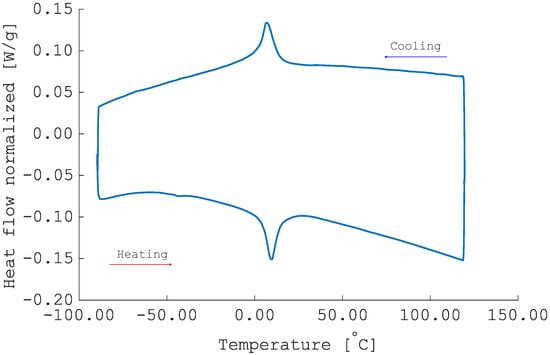
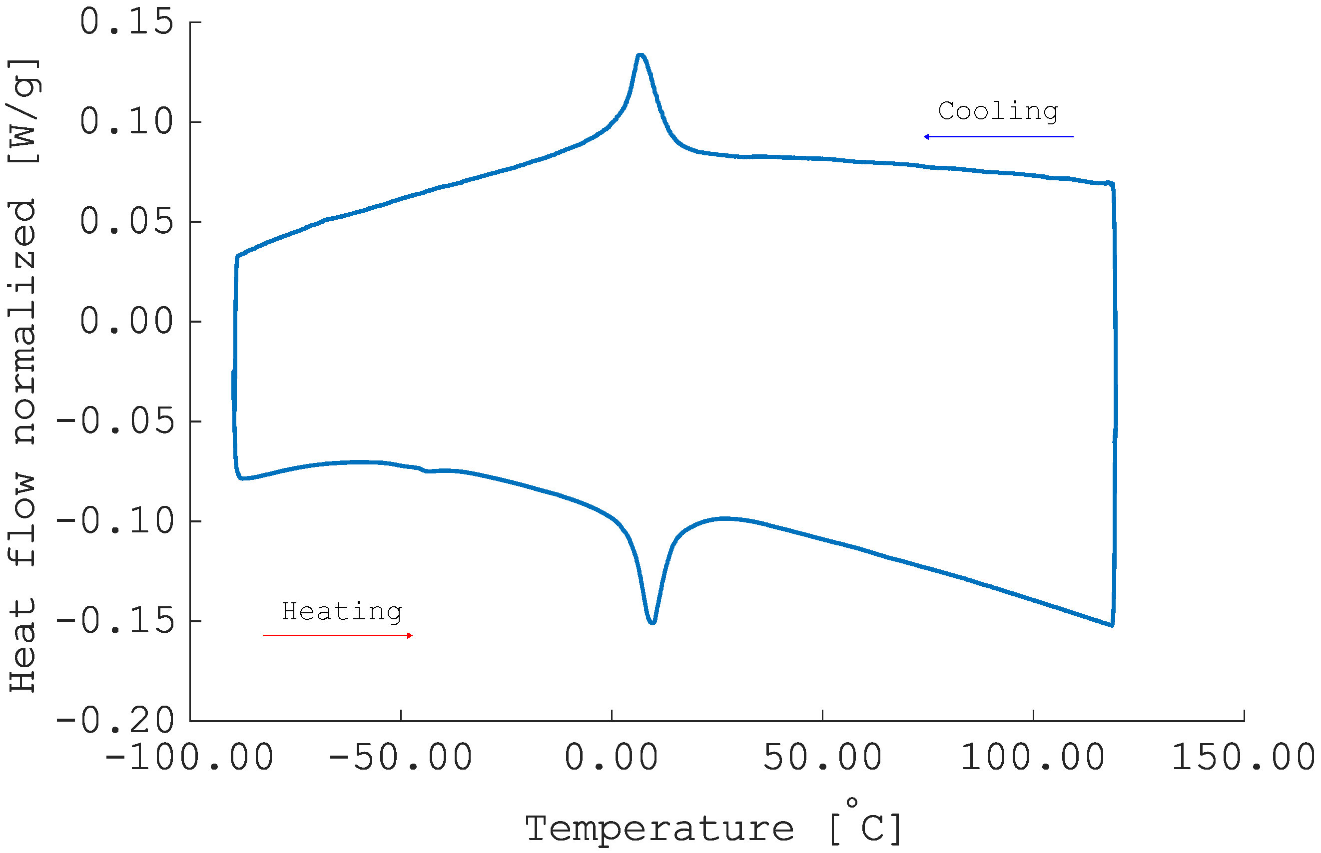
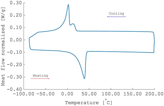
Zero-stress PTTs were evaluated using a differential scanning calorimeter (DSC) from TA Instruments-DSC 2010 with a heating/cooling rate of min. The results are depicted in Figure 4. The upper part of the curve shows the cooling behavior after preheating to C, whereas the lower curve is related to the heating process after 2 min of isothermal holding at C. Only one peak appears in both the cooling and heating branches. From the small hysteresis, we can conclude that this peak corresponds to the B2-R transformation. PTTs were calculated with Universal Analysis software (TA instruments) using the tangent line method and are = 13.0 °C, = 2.3 °C, = 3.7 °C, = 15.9 °C, confirming a pseudo-elastic behavior at room temperature for the material as received.
Figure 4.
DSC results of the as received 3mm pseudo-elastic NiTi tube.
PTTs needed to be increased as the shape memory effect is required for ground testing. The material was therefore subjected to aging treatments to exploit the precipitation reaction of the quenched supersaturated Ni-Ti solid solution, altering the composition of the Ni-Ti matrix and thus tuning the transformation temperatures [29].
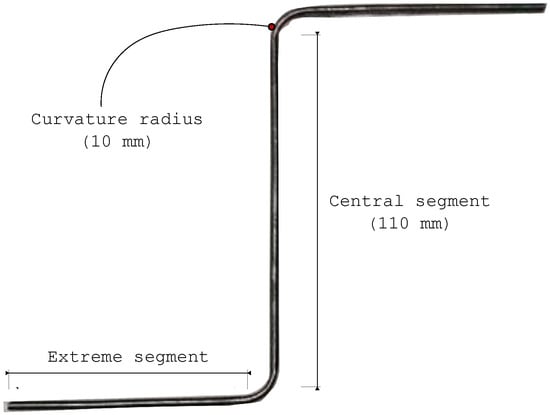
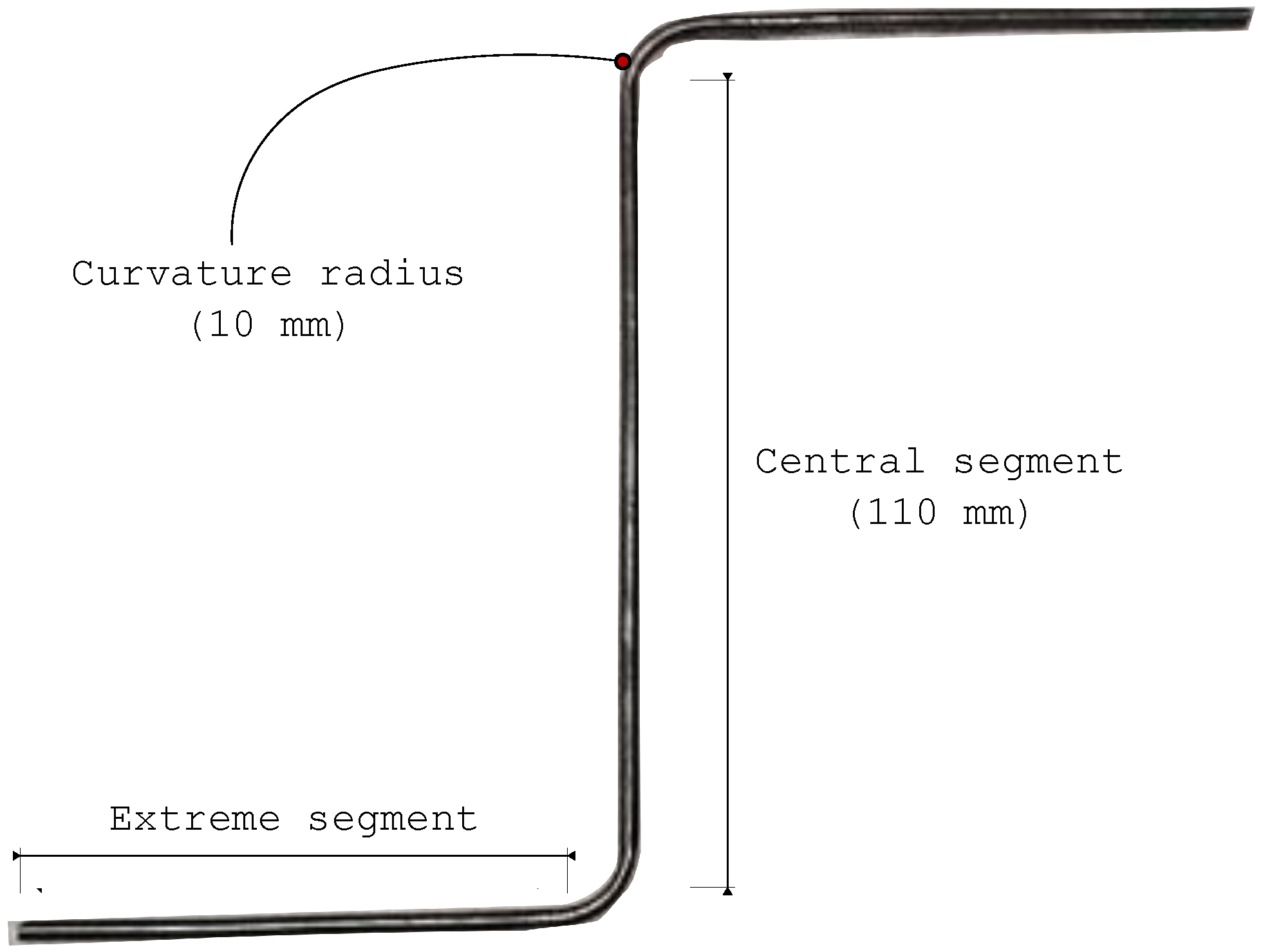
Shape setting was carried out simultaneously with aging to give the actuator the desired S-shape configuration. Specifically, the tube was first filled with sand, then manually formed into a mold and closed with the corresponding counter-mold. The complete set was aged in an oven at C for 45 min and then quenched in water at ambient temperature. The heat treatments were performed in air, as the short exposure time makes the oxidation effects negligible. No external load was applied during the closing of the mold, which ensured uniform contact and homogeneous heat transfer, monitored by thermocouples inserted in the mold. Therefore, a fairly uniform dispersion of precipitates is expected.
However, slight inhomogeneities may occur between the central portion of the tube and its end sections, as the latter partially protrude outside the mold during heat treatment. This does not represent a significant issue since the end sections are not involved in torsional deformation. The final result is depicted in Figure 5.
Figure 5.
Result of shape setting-ageing thermal treatment.
An additional DSC analysis was carried out on a fragment sample of the aged material to evaluate the Zero-stress PTTs, checking the effectiveness of the selected thermal treatment in terms of time and temperature parameters. The sample was tested between and C with heating/cooling rates of C/min, and 2 min of isothermal holding were imposed when maximum and minimum temperatures were reached. The new set of PTTs was calculated with the Universal Analysis software (TA Instruments, New Castle, DE, USA) using the tangent line method. Data derived from the DSC tests were used to define appropriate test temperatures for the subsequent thermo-mechanical characterization process.
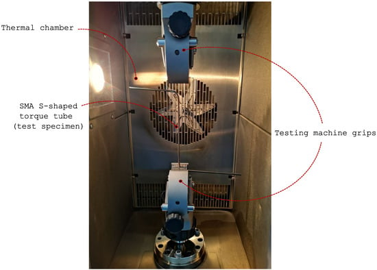
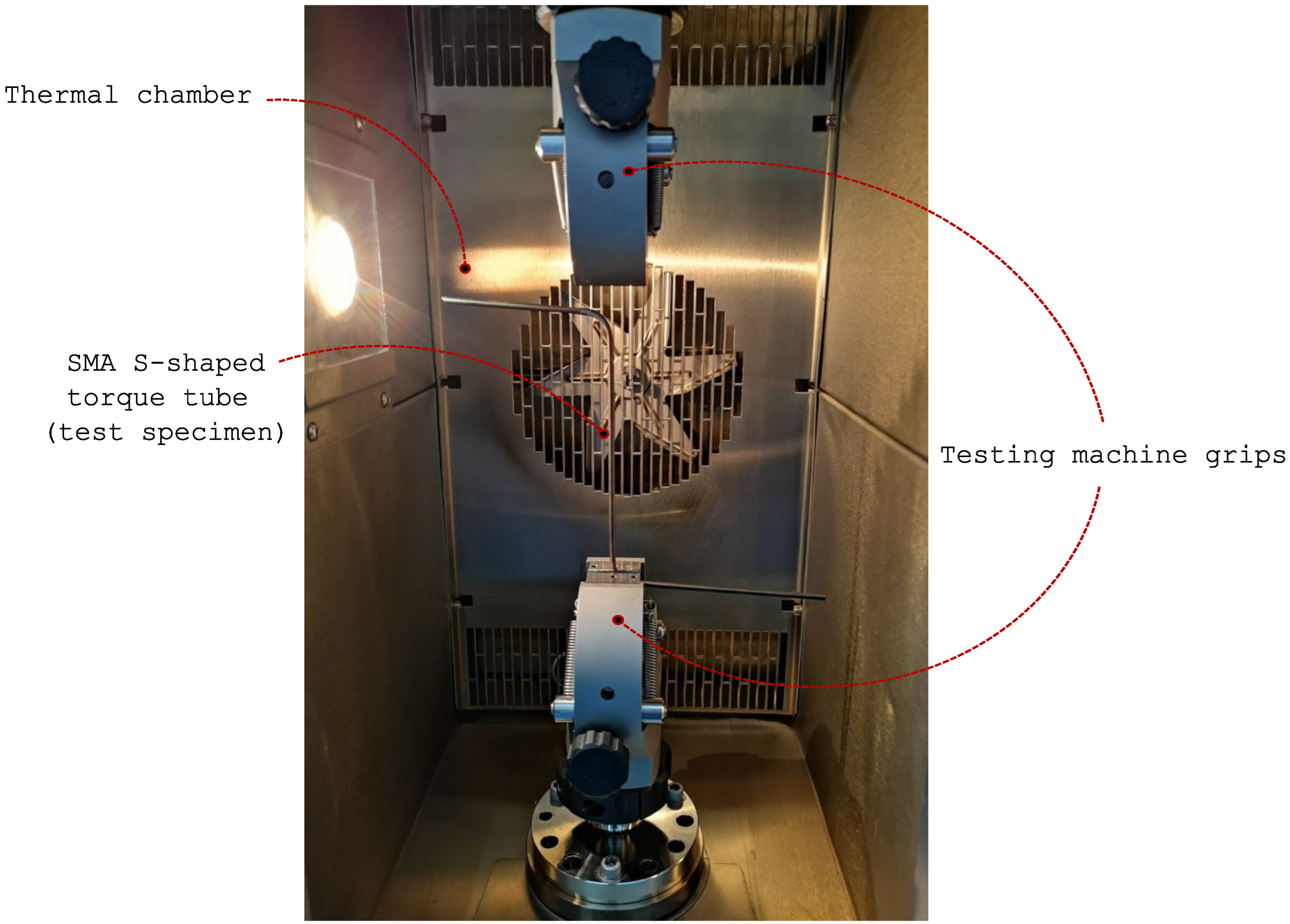
Aged specimens (110.0 mm gauge length) were tested under monotonic torsional loading in isothermal conditions at various temperatures ranging from C to C. The tubes were first heated above to recover any residual deformation and then clamped in a torsion dynamometer (Instron E3000 mechanical torsional equipment, Instron, Norwood, MA, USA) as depicted in Figure 6. Monotonic loading was performed in rotational control mode at /s with a uniaxial tensile preload of 10.0 N. Loading was maintained until a rotation of , corresponding to a shear strain of 4.3%, was reached. Unloading of the specimen was performed in the same manner as monotonic loading until the torque values were zero.
Figure 6.
Aged specimen partially mounted on the testing machine.
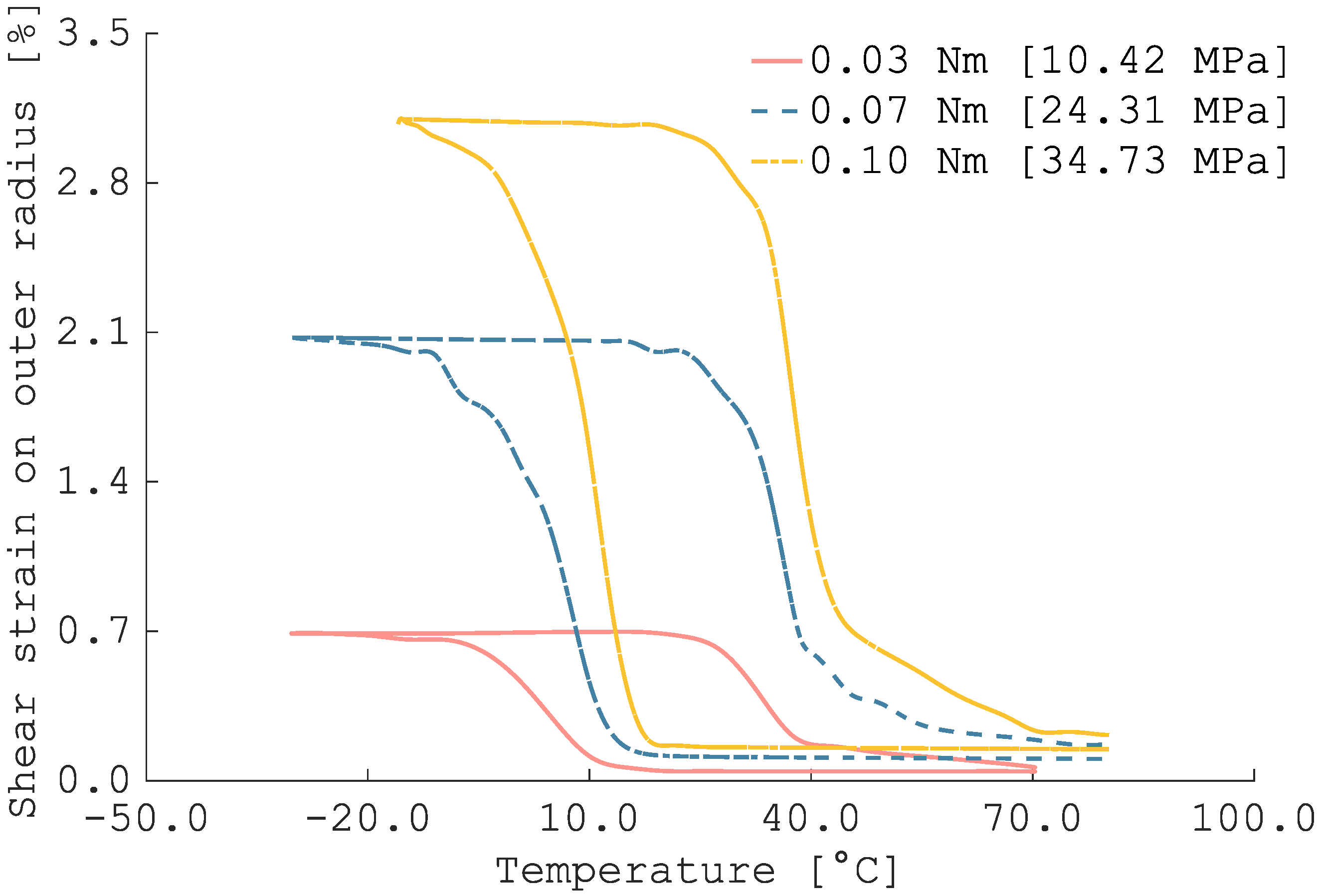
Thermally induced torsion recovery tests were performed on additional aged specimens using the same testing machine. The tubes were heated above , then a constant torque was applied and maintained while a cooling rate of C/min was applied until a temperature C was reached. In this way, the samples were forced to rotate until an equilibrium was reached between the applied load and the torque resisted by the tube in the martensitic phase. A heating rate of C/min was then applied until a temperature C was reached, resulting in strain recovery by SME. Three tests were performed with torques of 0.03 Nm, 0.07 Nm, and 0.1 Nm, respectively. Thermally induced torsion tests allow the determination of the PTTs at non-zero stress levels. For each test, the PTTs were extracted from the temperature-strain diagram using the tangent line method. A linear interpolation is then carried out to generate the phase diagram of the aged material.
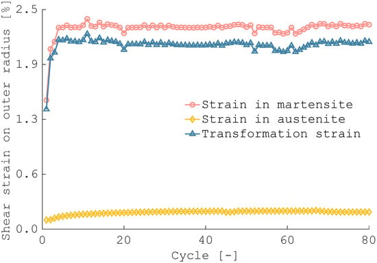
The cyclic response of the actuator was also investigated to train the material and assess the number of cycles over which the actuator provides a stable response. A 126.0 mm-long aged tube was subjected to 80 cycles of thermally induced torsion recovery tests with a constant torque of 0.07 Nm. The torque applied was defined on the basis of the results of the previous thermally induced torsion recovery tests, as it provides an outer tube rotation in martensitic conditions of 100°, which is close to the desired 90° required for the final application.
Let be the shear deformation at the end of the cooling process (stable martensitic phase) and the shear deformation at the end of the heating phase (stable austenitic phase). The actuator performance is evaluated considering the cyclic evolution of the shear transformation strain , defined as follows [30]:
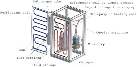
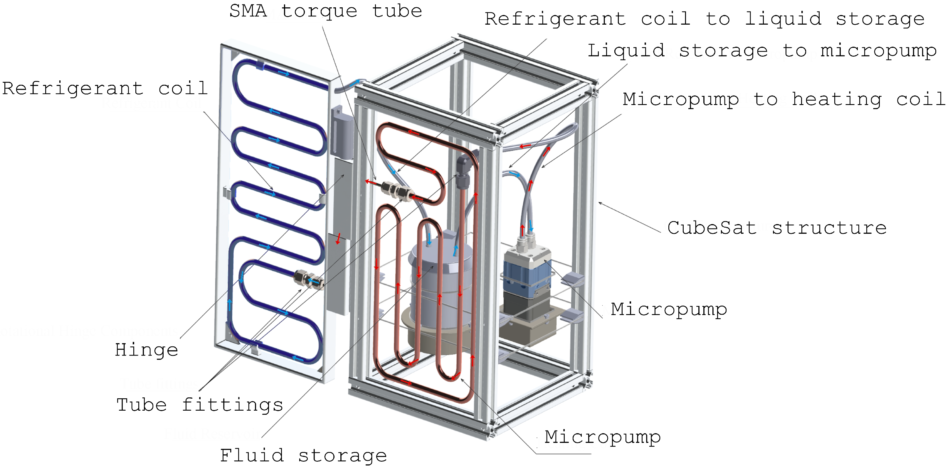
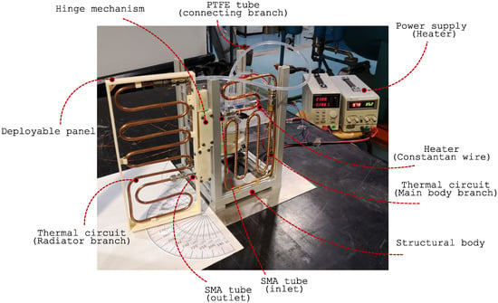
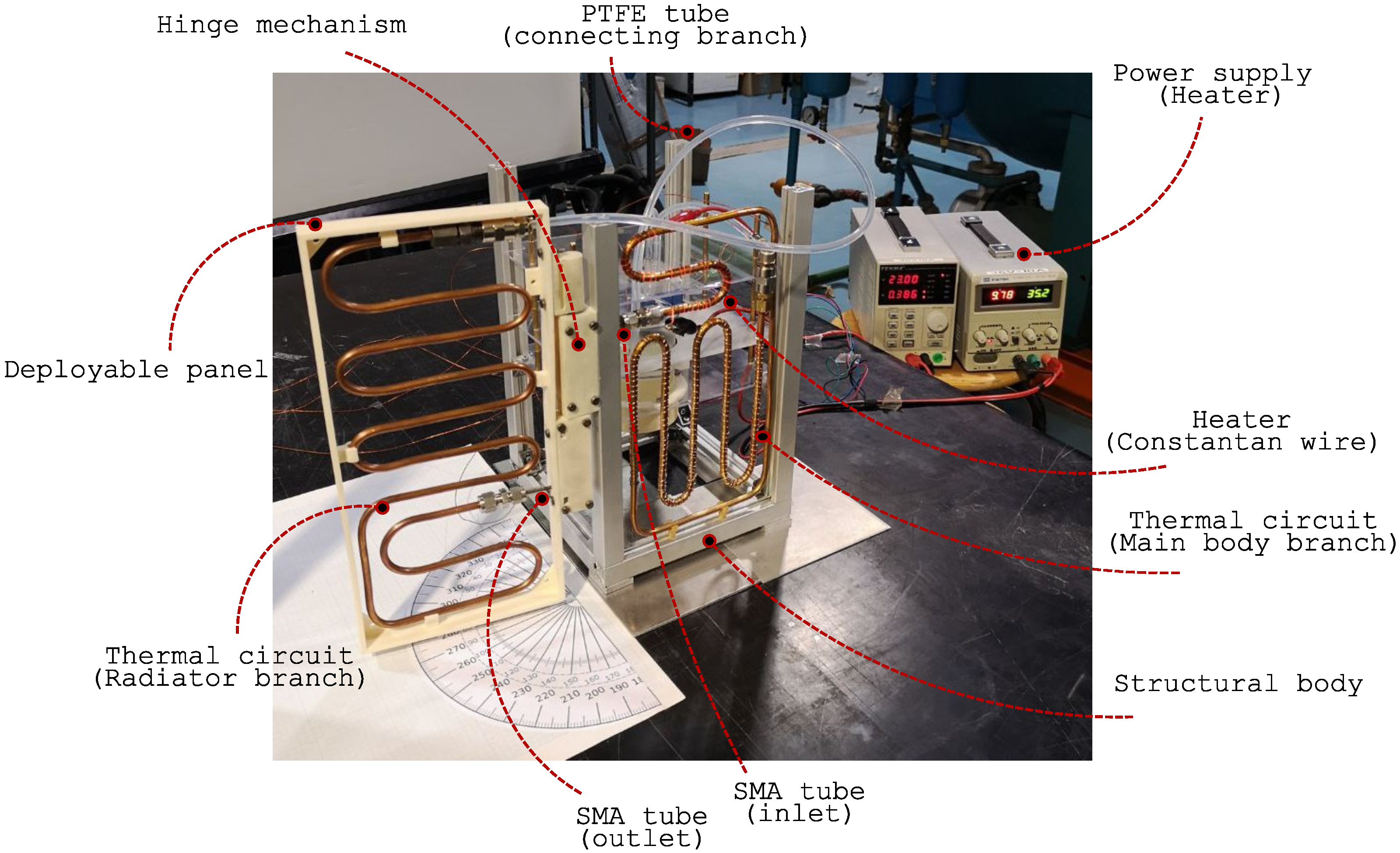
A conceptual prototype was constructed to assess the viability of the proposed solution through ground testing. The internal heating of the 12U CubeSat was reproduced in an experimental setting, whereas the experimental simulation of radiative cooling was postponed for further investigation. Consequently, no rearming mechanism was integrated into the prototype at this stage. Figure 7 depicts a CAD model of the prototype.
Figure 7.
CAD model of the prototype realized for ground testing. Panel is represented in fully deployed configuration. Arrows indicate the direction of the fluid flow.
The main body of the CubeSat is modeled with a skeleton frame made of Bosch aluminum profiles, the dimensions of which correspond to the 12U standard (i.e., 340.5 mm × 200.0 mm × 200.0 mm). An FDM (Fused Deposition Modeling) printed frame was produced to replicate the radiative panel. The frame was realized by a Stratasys Fortus 450 machine (Stratasys Ltd., Eden Prairie, MN, USA) with a 0.178 mm diameter nozzle. Acrylonitrile Styrene Acrylate (ASA) filament was used as the printing material. The panel was 340.5 mm high, 165 mm wide, and 27 mm thick.
The SMA tube is enclosed in a hinge mechanism to ensure that the actuator is aligned with the desired axis of rotation. This prevents the tube from undergoing any bending deformations as a result of the weight of the panel.
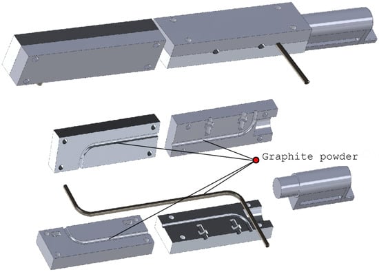
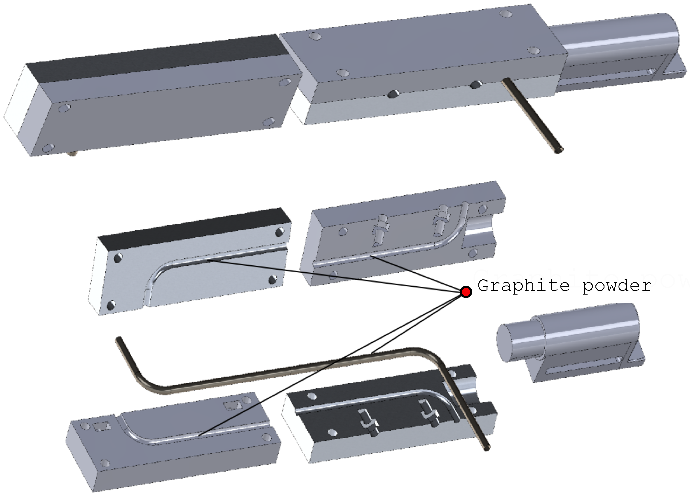
The hinge consists of two sets of mirrored elements that correspond to the shape of the mold used to fabricate the actuator. An additional component guarantees panel alignment and prevents it from bending under gravity. A CAD representation of the hinge mechanism is reported in Figure 8.
Figure 8.
CAD model of the torsional hinge actuated mechanism.
Once assembled, the two sets of mirror elements form two components, one of which is attached to the prototype main body and the other to the panel. Once the tube has been positioned under martensite state on one side of the mechanism, the remaining elements are connected to their mirrored counterparts using threaded bolts with removable nuts. The housing channel of the actuator in the hinge is coated with graphite powder to reduce friction between the parts. The two hinge components are then rotated 90° to each other, creating a torsional stress in the central part of the S-tube, and then connected to the corresponding structure. The whole set of hinge elements was FDM printed with ASA filament on the Stratasys Fortus 450 machine.
A mechanical pumped fluid loop (MPFL) is installed inside the prototype. Two copper coils with a diameter of 6 mm are attached to both the main body and the panel. The two coils are connected to the SMA tube end segments through stainless steel Swagelok bored-through reducing unions (6 mm × 3 mm tube OD, SS-6M0-6-3MBT). A conical revolution micropump (model R-404-ST-6-V, TCS Micropumps Ltd., Faversham, Kent, UK) circulates a propylene glycol solution. A liquid reservoir prevents the pressure from overshooting due to the heating of the liquid. Three flexible PTFE tubes with an outer diameter of 6 mm connect the two copper coils to the micropump and close the circuit Figure 7. The heating of the CubeSat is obtained with a 1.45 m long electrical Constantan wire wrapped around the copper coil clamped in the main body of the prototype, simulating the internal CubeSat heating source.
Ground testing of the prototype was performed to assess the feasibility of the proposed concept. The micropump was controlled using its dedicated driver that specifies a drive speed of 700 rpm, which corresponds to a flow rate of 70 mL/min. The panel opening was monitored with an optical camera equipped with an overhead view, including a graduated scale to read the actual rotation achieved during the process. A FLIR infrared camera was also mounted on the side to assess the dynamics of the MPFL temperature during the test. The power supply was switched on 8 s after data recording.
4. Results and Discussion
4.1. Material Characterization
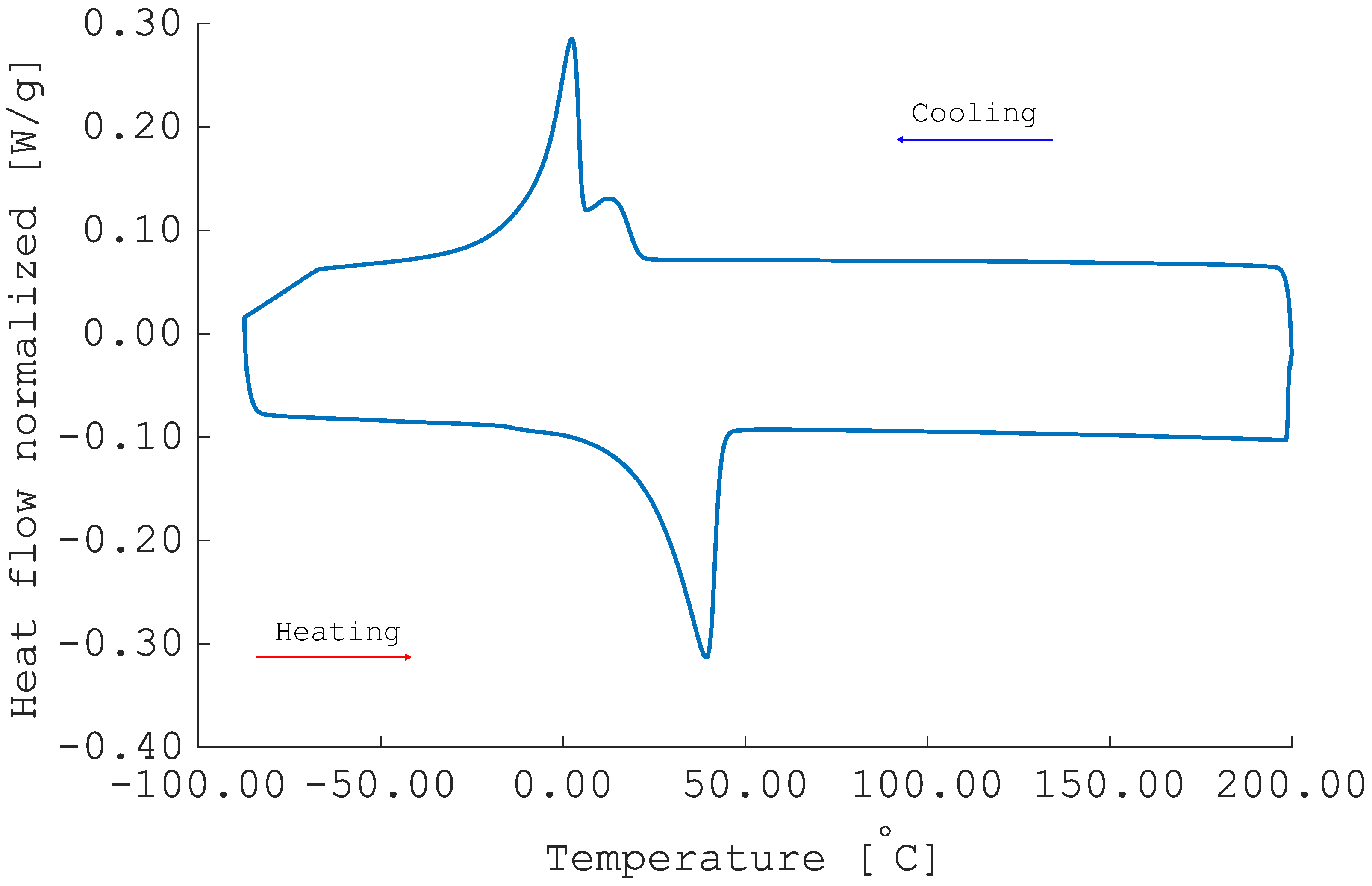
The DSC results of the aged material are depicted in Figure 9. They are consistent with the transformation behavior of aged Ti-Ni alloys [31]. The zero stress PTTs are = 20.9 °C, = −7.4 °C, = 23.0 °C, and = 43.3 °C. The B2-B19’ single-step transformation mechanism is visible in the cooling branch. Two partially overlapping exothermic peaks are detected and can be attributed to material inhomogeneity after Ni4Ti3 precipitation. The heating curve displays a single endothermic peak related to the B19’-B2 single-step martensitic transformation.
Figure 9.
DSC result of the treated specimen after 45 min at 570 °C ageing. Lower curve refers to heating behavior after 2 min of isothermal holding at −90 °C. Upper curve displays the cooling behavior after preheating at 200 °C.
The treatment parameters chosen are kinetically consistent with a pronounced but uniform precipitation of the Ni4Ti3 phase, as shown in Figure 9. A clear tuning of the PTTs is visible, with values approaching those compatible with the use of SME at ground test temperatures. However, an even more significant increase in the PTTs would be beneficial. The martensite finish temperature = −7.4 °C does not guarantee the completion of direct martensitic transformation at the reference temperature. Nonetheless, increasing the treatment parameters is not feasible. At higher temperatures, the material would be solubilized, whereas longer treatment times would lead to segregation of the precipitated phase [29,32]. The precursor material is a semi-finished product for pseudo-elastic applications. As expected, its chemical composition and manufacturing process are not optimized for the intended application. In view of higher Technology Readiness Levels (TRLs), materials specifically suited for the temperature range of the shape memory effect (SME) applications are strongly recommended. However, considering the preliminary nature of this investigation, the aged specimens are considered sufficient for the study.
The effects of the described treatment on the thermomechanical performance of the material need to be clarified. This aspect was evaluated using the standard procedure for the thermomechanical characterization of SMAs intended for actuation applications [26].
The testing apparatus employed throughout the thermo-mechanical characterization records both angular rotation and applied torque. Because the specimens are subjected to considerable loads, both geometric and material non-linearities arise during testing. Consequently, the accurate determination of shear strains and shear stresses through the tube wall is not straight forward.
In the ideal case of a material behaving in the linear-elastic regime, the shear stress distribution across the wall thickness is linear, and the maximum shear stress at the outer surface can be expressed as follows:
where T is the measured torque, and are the external and internal radii of the tube, respectively, and J denotes the polar moment of inertia [25].
When material nonlinearities are significant, more realistic estimates of shear stress can be obtained via alternative approaches. In the present work, the specimens have a thin wall , allowing for the simplifying assumption of a uniform shear-stress profile through the thickness. Under this hypothesis, the shear stress becomes [25]:
The most rigorous method recommended by ASTM standards [33] employs the iterative scheme of Brown et al. [34], an extension of Nadai’s solution [35] (valid for solid circular bars) for tubular specimens. This approach yields an exact closed-form reconstruction of the wall stress distribution directly from the material’s torque-rotation curve. However, its formulation does not readily accommodate the unloading branch of the experimental response.
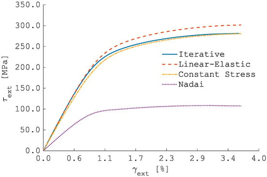
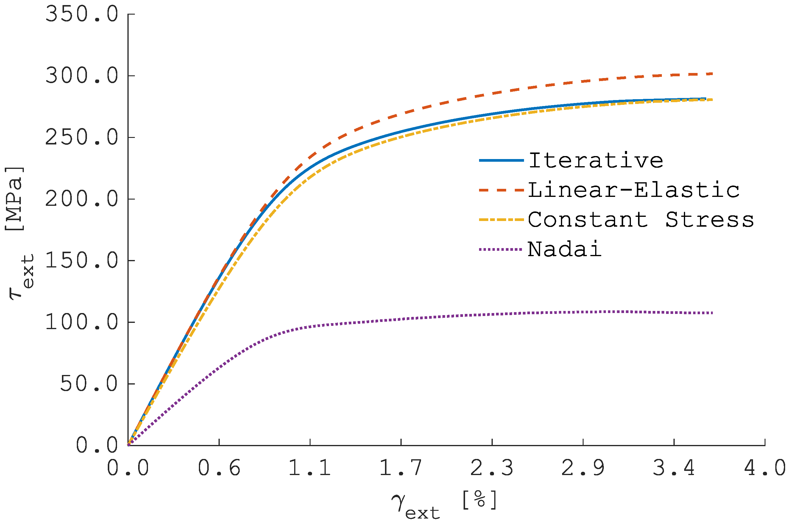
To assess the impact of these various assumptions, we compared four methods: (1) linear-elastic (Equation (4)), (2) constant-stress profile (Equation (5)), (3) Nadai’s solid-shaft solution, and (4) Brown’s iterative solution. The monotonic loading curve at 50 °C was used for this comparison. Figure 10 displays the resulting outer-wall shear-stress loading profiles.
Figure 10.
Comparison of outer-wall shear-stress profiles obtained via different estimation methods at 50 °C.
A qualitative and quantitative evaluation reveals that the linear-elastic assumption introduces a systematic bias: the maximum relative error of compared with the iterative benchmark is . The uniform-stress approximation deviates moderately from the exact solution, but its ease of implementation, particularly on the experimental unloading branch, motivates its adoption for subsequent data processing.
Finally, the shear strain at the outer surface, , is calculated according to Equation (2) [36].
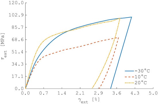
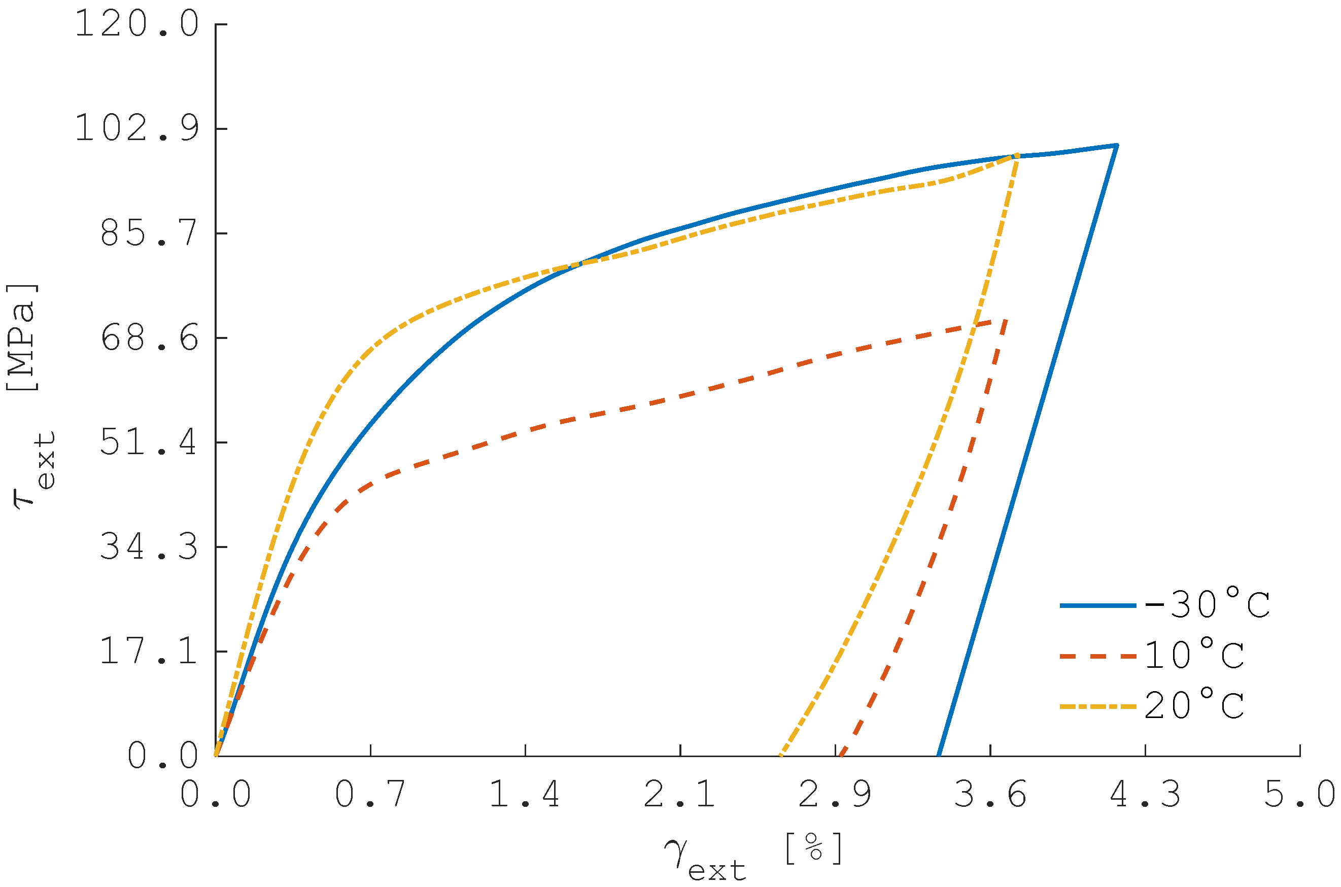
Figure 11 depicts the results from torsional monotonic isothermal loading tests at temperatures below . The curve at C was used to derive the shear modulus of martensite, which is estimated to be GPa ( = 0.9863). The detwinning start stress was also derived from this curve with the tangent line method and is equal to MPa [26].
Figure 11.
Isothermal monotonic torsional tests. Loading at T < Ms0: characterization of material behavior in martensitic conditions.
The samples tested at C and C exhibit pseudo-plastic deformations after unloading and , respectively, which correspond to and . Complete stress-free recovery is observed for both samples when heated above . Similarly, the specimen tested at T = C exhibits complete stress-free recovery, but the residual strain after unloading is lower. As anticipated, at this temperature the material begins to transform, leading to a hybrid behavior between SME and pseudo-elasticity.
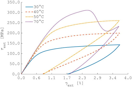
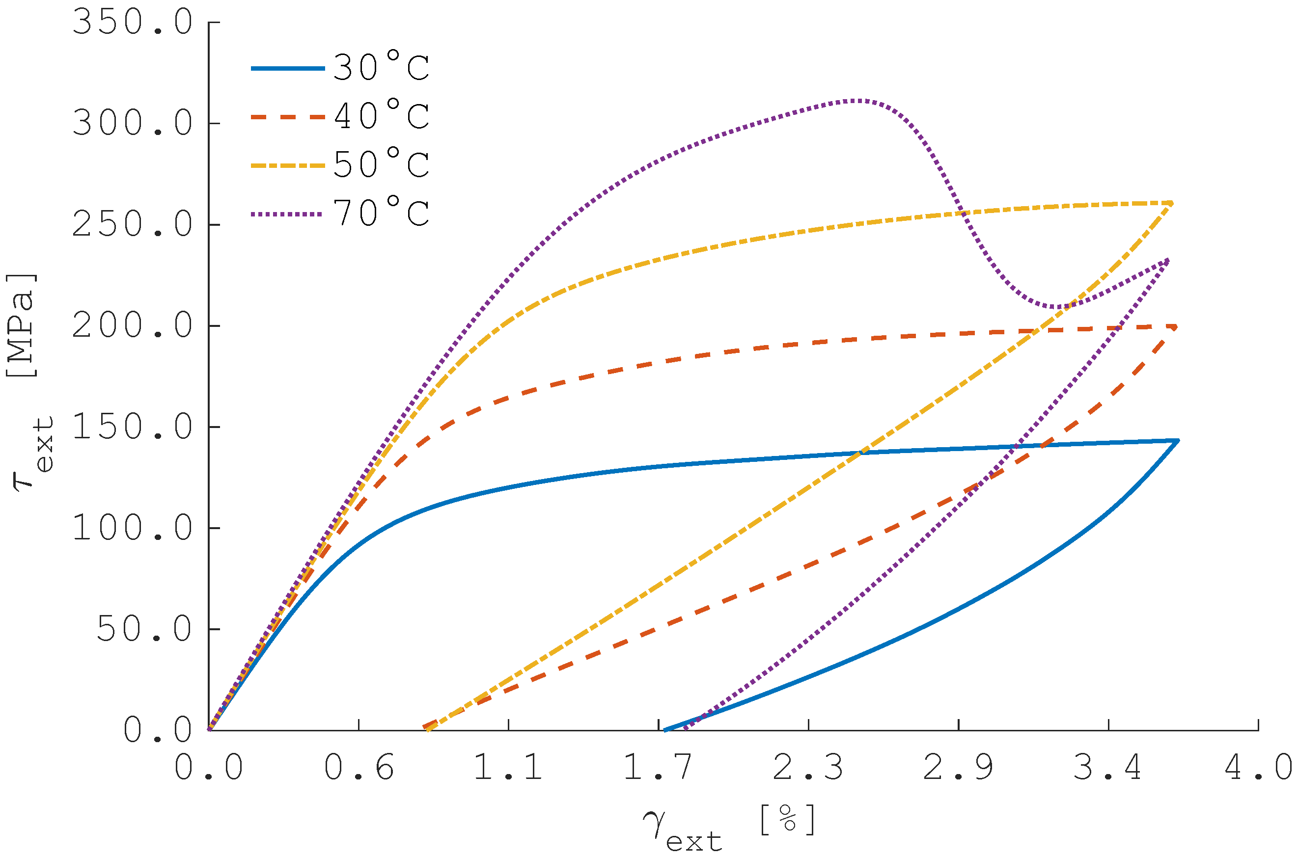
Figure 12 depicts results of tests conducted at temperatures exceeding . As expected, the stress levels required to cause material detwinning, along with the observed strain recovery post-unloading, rise with temperature. None of the tests achieve complete deformation recovery during the unloading phase, and all curves lack the characteristic flag-shaped behavior generally observed in SMAs. This suggests that the stress levels required to conclude the stress-induced martensite (SIM) process are higher than those needed to yield the material. In support of this consideration, residual plastic deformations were detected in samples tested at 40 °C and 50 °C after unloading. Furthermore, the irregular behavior of the curve at T = 70 °C is due to the sample plastic failure during the experiment. The shear modulus of austenite, derived from the data corresponding to T = 70 °C, is GPa ( = 0.9999).
Figure 12.
Isothermal torsional loading results. Loading at T > Ms0: characterization of material behavior as austenite phase is progressively generated. Purple curve displays an abnormal trend in the last part of loading due to specimen plastic failure.
As a general remark, the results of the isothermal monotonic torsion tests indicate that ageing treatment does not significantly compromise the mechanical performance of the material. Since a prestrain of (see Section 2.2) must be applied to the actuator to achieve a rotation of 90°, it is crucial to assess whether this prestrain is compatible with the mechanical strength of the material. Specimens tested at exhibit residual strains upon unloading exceeding , which are fully recovered upon heating. Therefore, it can be concluded that the required prestrain can be safely applied without inducing plastic deformation.
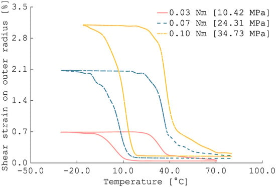
Figure 13 depicts the results of the thermally induced torsion recovery tests at different torque levels. For all stress levels, full strain recovery is observed, aside from minor residual strains, which are primarily attributed to the progressive stabilization of the material.
Figure 13.
Thermally induced torsion-recovery curves for to three different applied torques. Legend entries give the nominal torque (Nm) and, in parentheses, the corresponding shear stress (MPa), calculated from the uniform stress assumption of Equation (5).
The evolution of PTTs as a function of the applied stress on the external tube radius is reported in Table 1. The results indicate a limited difference in the stress-free PTTs measured through DSC analysis. DSC samples were necessarily taken from the tube ends, which protrude from the mold during processing. In contrast, the main part of the actuator is positioned between the mold and the counter-mold. Thermal inertia may affect the actual treatment parameters, resulting in somewhat process inhomogeneity. As a result, the zero-stress PTTs obtained from thermally induced torsional recovery tests are deemed more reliable, as they provide a more representative measure of the thermomechanical properties of the entire actuator.
Table 1.
Variation in PTTs as a function of the applied shear stress level. Shear stress is evaluated using the uniform stress assumption of Equation (5).
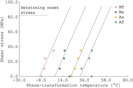
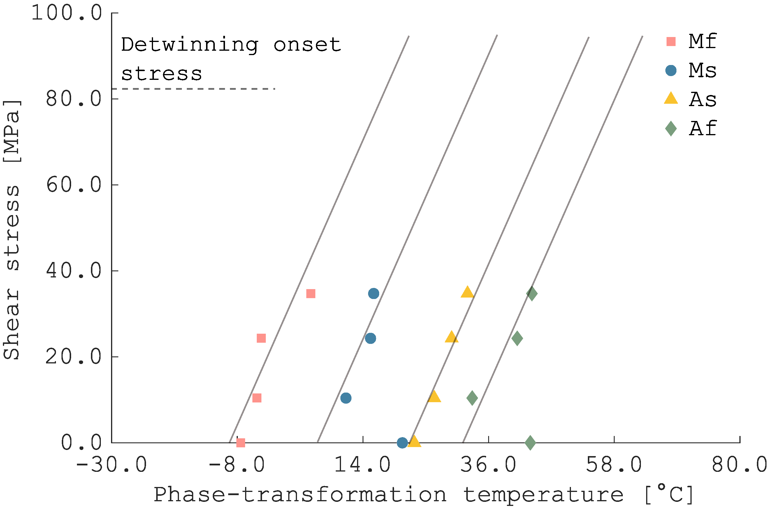
The stress influence coefficients for martensite and austenite were obtained through a linear regression of the data in Table 1, and are as follows: , , , and . Data collected from thermomechanical characterization were used to define the phase diagram of the treated material, as reported in Figure 14.
Figure 14.
Phase diagram of the material constructed using characterization data.
In a potential space application, the actuator only needs to overcome the resistance of the reset system. The red and green curves in Figure 13 prove the actuator’s ability to fully recover strains (i.e., rotations ) against torques up to T = 0.1 Nm. However, the higher the resisting torque, the lower the cyclic stability of the material. For this reason, the cyclic stability was investigated at T = 0.07 Nm, being the minimum resistive load at which the actuator successfully performs the desired movement.
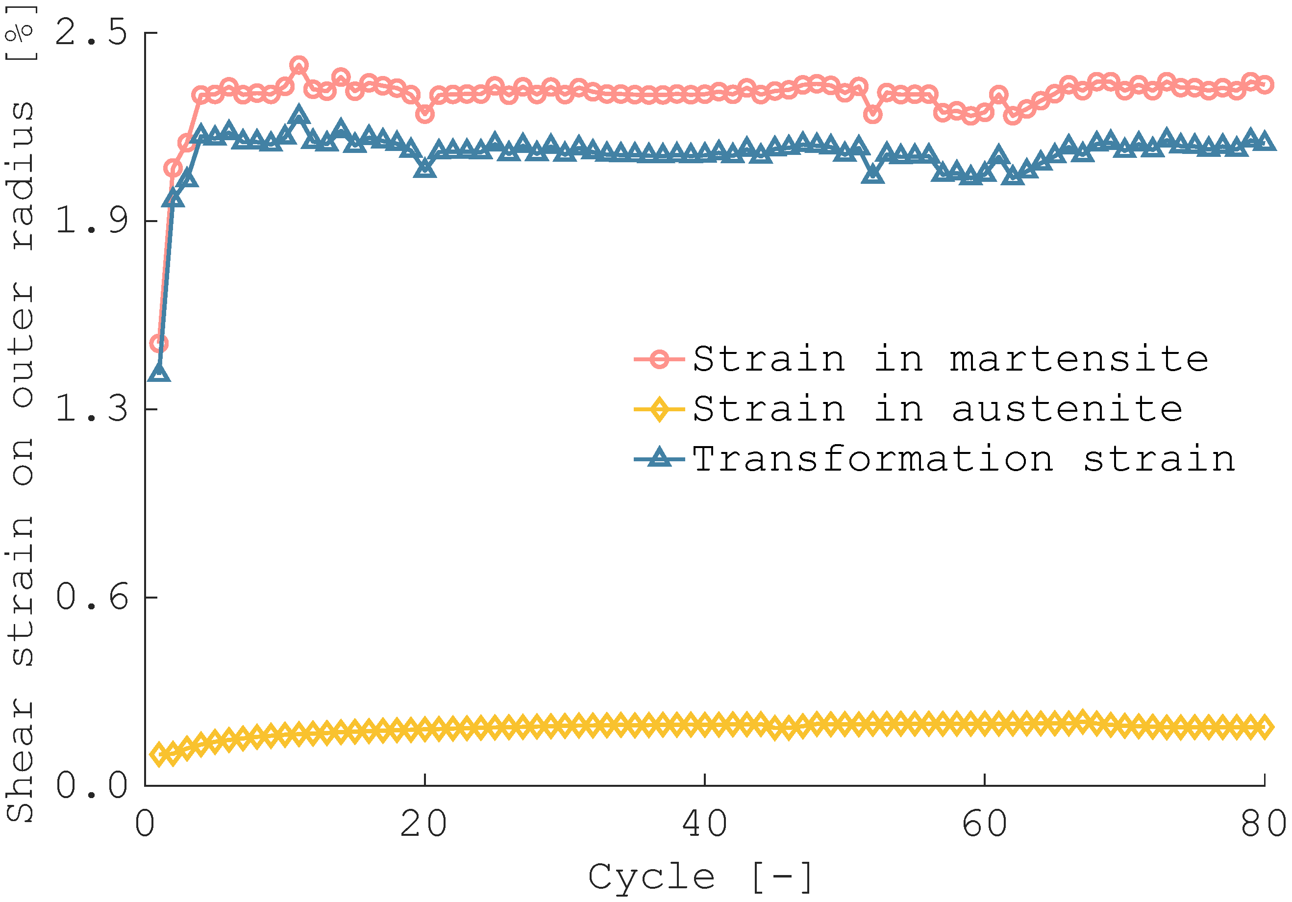
The results of 80 thermally induced torsion recovery cycles are presented in Figure 15. The material stabilizes rapidly within the first ∼4 cycles and remains stable throughout the remainder of the cycles.
Figure 15.
Cyclic behavior of the aged material under 80 thermally induced torsion recovery tests at Nm.
To assess whether this low-cycle campaign covers the needs of a real scenario space application, material data are complemented with an operationally conservative estimate of the number of deployment cycles that a 12U-class system could plausibly face over its lifetime. The estimate intentionally ignores thermal inertia and attitude constraints of the system and is therefore a roof, not a recommended operating strategy. Nevertheless, it may provide a worst-case clear upper bound for preliminary design considerations.
A per-orbit toggling rule is considered: during an entire orbit, the radiator opens and closes whenever segments of eclipse and sunlight are encountered, respectively. Looking at the maximum number of cycles per day, while remaining representative of common SmallSat missions, a circular sun-synchronous (SSO) low-Earth orbit (LEO) that is not dusk–dawn is considered. This choice ensures that a per-orbit cycle is possible (there is both light and shadow in each orbit) and keeps the orbital period short, as is typical of LEO, thus maximizing the number of orbits per day. By contrast, dawn-dusk SSO often experiences long no-eclipse seasons (i.e., they are less demanding), and higher altitudes reduce the number of orbits per day.
Under the two-body approximation [37], the orbital period T at altitude h is
with Earth mean radius km and . The orbits completed per day can be computed as follows:
With the assumption of a per-orbit toggling rule, the number of deployment cycles per day equals . Different missions in terms of operational life and altitude h are compared, and results are reported in Table 2.
Table 2.
Upper-bound estimation of deployment cycles for a 12U CubeSat in circular LEO orbits.
Typical SSO LEO missions would thus demand a stable deployment cycle under a conservative per-orbit deployment assumption in the case of a 5-year operational life, which is a realistic scenario (also considering the upcoming rules for space debris mitigation) [cit]. In an operational scenario, the demanded cycles will be lower due to thermal inertia effects and the absence of eclipse seasons. Also, fine thermal regulations might be addressed by the pumped fluid loop (flow/bypass modulation), whereas geometry changes related to autonomous deployment can be designed in the context of each mission to occur only in the presence of high thermal loads, thereby reducing material and system requirements related to cyclic deployments and improving mission reliability.
Nonetheless, proper material selection may comply with missions requiring frequent geometric changes in terms of radiating area [38]. In the context of this work, stable behavior is observed under torsional loading throughout the 80 cycles investigated. The minor observable drifts after stabilization are related to the high heating and cooling rates used, which are necessary for reducing experimental time in cycling tests. Although these low-cycle fatigue results do not demonstrate material capabilities to meet real operational scenario requirements, they offer preliminary insights regarding functional fatigue under torsional loading modes for SMAs. Even with a non-optimized material microstructure, the material response was not compromised in the low cycle regime. By contrast, tensile loading modes are associated with poor and non-stable behavior, even in low-cycle regimes [39]. This suggests that torsional SMA actuators can be a more reliable solution for space deployables. Future investigations will clarify this aspect.
Based on the data collected during the material characterization, we conclude that the actuator meets the necessary requirements to be tested as part of the technological demonstrator. The stress levels required to deform the material in the martensitic state according to the design specifications are well below the yielding point. Stable and repeatable rotations of are ensured under torques of up to Nm.
The only remaining point to be investigated lies in the stress-free PTTs, which prevent a complete direct martensitic transformation at room temperature. The actual performances of the prototype were tested by placing it in a cooling chamber at C after each opening of the panel (ensuring a complete martensitic state); under these conditions, the actuator was reset by forcing the panel to close.
4.2. Prototype Testing
The experimental tests carried out on the prototype revealed a two-stage behavior in the panel deployment dynamics. The panel started to rotate approximately 8 s after the activation of the electrical resistor. The initial phase of deployment was characterized by a sharp angular acceleration, during which the system rotated by 72° within 7 s. This was followed by a slower and more controlled motion lasting about 140 s, after which the system stabilized at a final angle of (Figure 16).
Figure 16.
Configuration of the prototype at the end of the deployment test.
The results confirm the feasibility of the proposed concept, although the final angle achieved was slightly below the design target of . To clarify the underlying causes of this deviation, a more detailed discussion is provided below.
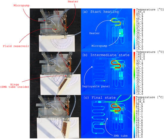
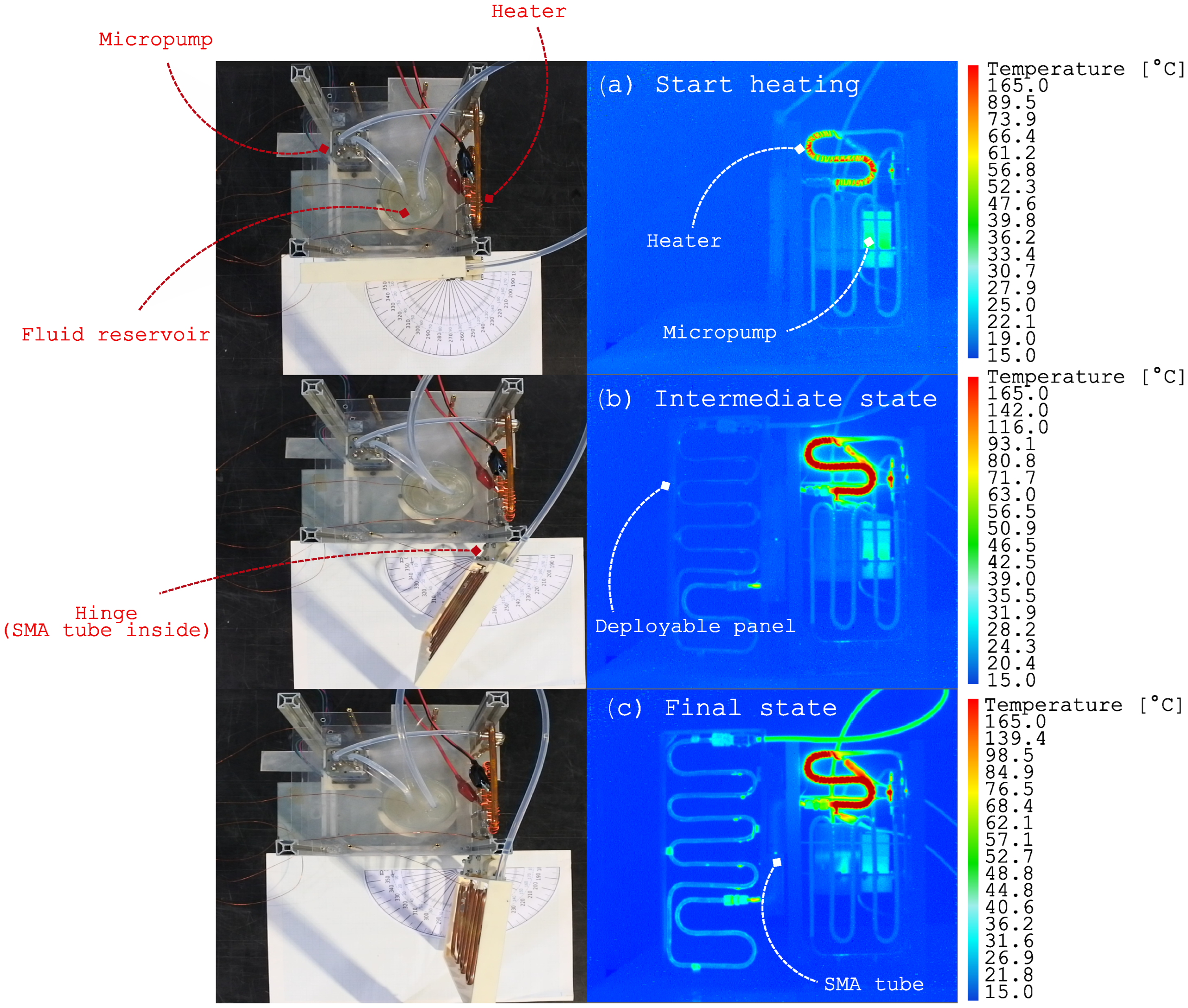
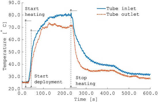
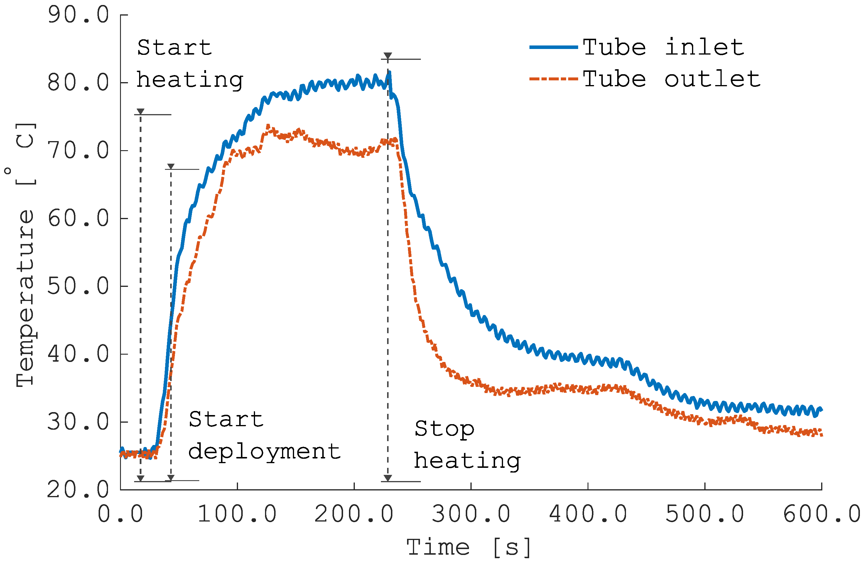
Figure 17 presents the top-view images and side-view thermographs recorded during different stages of the deployment process. The thermographs highlight how the circulation of hot fluid within the loop heats the actuator beyond the maximum temperature observed in the thermally induced torsion recovery tests, which corresponds to a torque of Nm according to Figure 13. This observation is supported by thermocouple measurements of the SMA tube temperature at the inlet and outlet of the fluid path. The corresponding temperature evolution as a function of time is depicted in Figure 18.
Figure 17.
FLIR infrared camera recording panel deployment. (a) Situation at 5 s after power supply is switched on. (b) Intermediate situation of deployment observed 22 s after heater activation. (c) Situation at 87 s after power supply is switch on. Panel is fully deployed and circulating liquid is hot. The geometrical shape of NiTi tube is recognizable even if it is enclosed in hinge mechanism.
Figure 18.
Thermocouple data: comparison between tube inlet and outlet temperatures.
During the heating phase, the peak values were approximately C and C, well above the transformation temperatures determined during material characterization. However, it should be recalled that phase transformation temperatures (PTTs) are conventionally extrapolated [30] from thermally induced strain recovery tests using the tangent-line method, which provides only an average indication of the completion of the phase transformation. As shown in Figure 13, for all applied torque levels, the strain recovery process continues beyond the graphically estimated , and higher applied torques lead to a greater amount of strain recovery over extended temperature ranges.
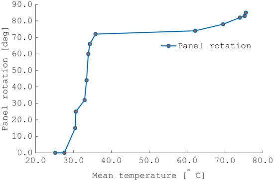
Figure 19 shows the angular displacement of the panel as a function of the mean actuator temperature, calculated as the average of the inlet and outlet values. The trend reveals a rapid recovery phase for a very narrow temperature range consistent with material characterization data, followed by a smoother completion of the transformation in a wider range at higher temperatures.
Figure 19.
Deployment angle as a function of mean temperature between SMA tube inlet and outlet.
The dual nature of the deployment observed in the experiments is consistent with the thermomechanical response observed in Figure 13, suggesting that additional thermal power could provide improved deployment levels.
Nonetheless, even under the conditions achieved in the present work, the temperature increase required to fully deploy the panel is significant and likely incompatible with realistic operational scenarios. To mitigate this limitation, the use of optimized materials specifically tailored for the application is necessary. As previously mentioned, the tuning of the alloy composition allows SMAs to be adapted to a wide range of operational environments. Moreover, with an appropriate thermomechanical processing history, it is possible to reduce the transformation ranges and consequently relax the heating requirements, as demonstrated in previous studies [29].
Other concurrent factors that may have limited full deployment include the frictional resistance within the hinge mechanism and the stiffness of the PTFE tube closing the thermal loop [40]. Further experimental investigation is planned to quantify these effects, although proper system design may accommodate these differences. For instance, the SMA hinge could be annealed with a slightly larger pre-twist between its ends to increase the available stroke during transformation [18], while potential over-deployment could be easily prevented by introducing a mechanical stop.
In the context of space applications, the relatively high angular accelerations observed during the initial phase of deployment raise concerns about potential impacts on the spacecraft’s attitude control and overall stability. Further studies will address this issue, focusing on strategies to obtain smoother and slower deployment profiles suitable for in-orbit operations.
5. Conclusions
In this study, an SMA torque tube actuator is proposed for the autonomous and energy-free deployment of radiative surfaces on SmallSats.
Monotonic isothermal and thermally induced torsional tests demonstrate the capability of the material to be deformed and then fully recover to the design strain levels without plasticity. The selected heat treatment shows that the adjustment of the PTTs to extreme values does not excessively compromise the SME performance of the material. During cyclic tests, stabilization occurs after four cycles, and transformation strains remain stable throughout the 80 cycles investigated.
Valuable preliminary evidence of functional fatigue resistance under torsional modes is provided. In contrast to the well-known poor cyclic stability under tensile loading, the present findings suggest that torsional actuation offers a more reliable and robust approach for SMA-based deployable systems, even when the material microstructure is not fully optimized.
Although promising, these findings characterize the material’s functional fatigue response only under the very low cycle regime. The precipitation treatments employed do not yield a crystal structure optimized for robust functional fatigue assessment, which is why high cycle investigations were not pursued.
In future work, it will be essential to select alloy compositions specifically tailored for SME applications within the target temperature window to enable a comprehensive study of functional fatigue. It must also be emphasized that such an investigation presents significant experimental challenges: unlike conventional mechanical fatigue, where specimens can be cycled at high frequencies with relative ease, functional fatigue demands thermal cycling and thus inherently longer test durations, largely driven by the cooling phase. Consequently, the development of a testing apparatus capable of minimizing cycle times, while still accurately imposing the required thermal profiles, will be crucial for advancing the understanding of high-cycle functional torsional fatigue.
The parameters obtained from the material characterization might serve as a reference for the preliminary design of SMA-based torsional actuators. Additionally, they may be useful for calibrating constitutive models, given the limited availability of such data in the literature.
In the prototype testing, the deployment levels observed (85°) were close to the required design levels (90°), demonstrating the feasibility of the proposed solution and validating the design approach in the context of preliminary system sizing.
In conclusion, this study demonstrated that the SMAs inherent environmental sensibility can be effectively used as a design tool for space deployable radiators. In particular, the investigation showed that appropriate system design can lead to overall energy savings through autonomous deployment driven by the SMA phase transformation, a reduction in system complexity through the integration of the SMA actuator as a functional part of the thermal control circuit, and the achievement of high deployment levels consistent with design requirements.
Several questions remain open. The inherent sensitivity of SMAs to environmental conditions, while advantageous from a design perspective, may also pose challenges for actuator adaptability under mission-dependent temperature variations. This issue must be carefully assessed within the context of each specific mission and platform. Accidental actuator activation can be mitigated through appropriate system design; for example, by implementing suitable thermal insulation strategies.
Despite these open questions, NiTi-based SMAs offer the advantage of a tunable chemical composition. During the design phase, the alloy can be tailored to meet the specific requirements of different missions and systems.
The high angular accelerations observed during prototype testing will require mitigation to achieve a smoother deployment profile. Moreover, the development of a mechanical reset mechanism for the actuator is necessary to enable cyclic deployment, ensuring that the radiator panel opens to dissipate heat and closes once the thermal requirement has been fulfilled.
Author Contributions
Conceptualization, P.B. and L.A.D.L.; methodology, F.C., D.R., F.V., and E.V.; software, F.C., F.V., and E.V.; validation, F.C. and D.R.; formal analysis, F.C. and D.R.; investigation, F.C., F.V., E.V., A.M.G., L.A.D.L., and D.R.; resources, P.B. and E.V.; data curation, F.C.; writing—original draft preparation, F.C. and D.R.; writing—review and editing, F.C., F.V., E.V., A.M.G., L.A.D.L., and P.B.; visualization, F.C.; supervision, D.R., E.V., A.M.G., and P.B.; project administration, P.B. and L.A.D.L. All authors have read and agreed to the published version of the manuscript.
Funding
The present work has been supported by the collaboration agreement between ASI and Politecnico di Milano “Attività di ricerca e innovazione” n. 2018-5-HH.0. Funded by the European Union-Next Generation EU, Mission 4 Component 1 CUP D43C23002530001.
Data Availability Statement
The original contributions presented in this study are included in the article. Further inquiries can be directed to the corresponding author(s).
Acknowledgments
The authors gratefully acknowledge Alberto Riccardo Donati, Cristian Ferretti, and the technical staff of the DAER laboratories for their valuable support.
Conflicts of Interest
The authors declare no conflicts of interest.
Abbreviations
The following abbreviations are used in this manuscript:
| SMA | Shape Memory Alloy |
| DSC | Differential scanning calorimetry |
| PTT | Phase transformation temperature |
| TMS | Thermal management system |
| PE | Pseudo-elasticity |
| SME | Shape memory effect |
| MAE | Material adhesion experiment |
| LFSA | Lightweight flexible solar array |
| OWSME | One-way shape memory effect |
| TWSME | Two-way shape memory effect |
| PFL | Pumped fluid loop |
| FDM | Fused Deposition Modeling |
| ASA | Acrylonitrile Styrene Acrylate |
| MPFL | Mechanical pumped fluid loop |
| TRL | Technology Readiness Level |
| SIM | Stress-induced martensite |
References
- Sadin, S.R.; Davis, R.W. The smallsat revolution…back to the future? Acta Astronaut. 1994, 34, 109–122. [Google Scholar] [CrossRef] [Scilit]
- Poghosyan, A.; Golkar, A. CubeSat evolution: Analyzing CubeSat capabilities for conducting science missions. Prog. Aerosp. Sci. 2017, 88, 59–83. [Google Scholar] [CrossRef] [Scilit]
- Sweeting, M.N. Modern Small Satellites-Changing the Economics of Space. Proc. IEEE 2018, 106, 343–361. [Google Scholar] [CrossRef] [Scilit]
- Villela, T.; Costa, C.A.; Brandão, A.M.; Bueno, F.T.; Leonardi, R. Towards the Thousandth CubeSat: A Statistical Overview. Int. J. Aerosp. Eng. 2019, 2019, 5063145. [Google Scholar] [CrossRef] [Scilit]
- McIntosh, D.M.; Baker, J.D.; Matus, J.A. The NASA Cubesat Missions Flying on Artemis-1. In Proceedings of the 34th Annual Small Satellite Conference, Pre-Conference Workshop Session VII: Instruments/Science II, Utah State University, Logan, UT, USA, 28 July 2020; Available online: https://digitalcommons.usu.edu/smallsat/2020/all2020/44/ (accessed on 12 February 2024).
- Ali, A.; Mughal, M.R.; Khan, S.A.; Teng, K.S. Thermal modeling and empirical verification of multi unit small satellites. Results Eng. 2025, 25, 104217. [Google Scholar] [CrossRef] [Scilit]
- Hengeveld, D.; Wilson, M.; Moulton, J.; Taft, B.; Kwas, A. Thermal Design Considerations for Future High-Power Small Satellites. In Proceedings of the 48th International Conference on Environmental Systems, Albuquerque, NM, USA, 8–12 July 2018. [Google Scholar]
- Miyazaki, Y. Deployable Techniques for Small Satellites. Proc. IEEE 2018, 106, 471–483. [Google Scholar] [CrossRef]
- Hengeveld, D.W.; Moulton, J.A.; Lockyer, S.C.; Taft, B.S.; Kwas, A.M. Enabling High-Power SmallSats with Advanced Thermal Management. In Proceedings of the 33th Annual Small Satellite Conference, Swifty Session II, Logan, UT, USA, 1 August 2019; Available online: https://digitalcommons.usu.edu/smallsat/2019/all2019/292/ (accessed on 27 November 2024).
- Yendler, B.; Meginnis, A.; Reif, A. Thermal Management for High Power Cubesats. In Proceedings of the 34th Annual Small Satellite Conference, Pre-Conference Workshop Session VI: Advanced Concepts III, Utah State University, Logan, UT, USA, 28 July 2020; Available online: https://digitalcommons.usu.edu/smallsat/2020/all2020/41/ (accessed on 28 November 2024).
- Wang, B.; Zhu, J.; Zhong, S.; Liang, W.; Guan, C. Space deployable mechanics: A review of structures and smart driving. Mater. Des. 2024, 237, 112557. [Google Scholar] [CrossRef] [Scilit]
- Section 1—Introduction. Shape Memory Alloy Engineering, 2nd ed.; Concilio, A., Antonucci, V., Auricchio, F., Lecce, L., Sacco, E., Eds.; Butterworth-Heinemann: Boston, MA, USA, 2021; p. 1. [Google Scholar] [CrossRef] [Scilit]
- Guzik, A.T.; Benafan, O. Design and Development of CubeSat Solar Array Deployment Mechanisms Using Shape Memory Alloys. In Proceedings of the 44th Aerospace Mechanisms Symposium, San Jose, CA, USA, 16–18 May 2018. [Google Scholar]
- Guo, W.; Li, Y.; Li, Y.Z.; Zhong, M.L.; Wang, S.N.; Wang, J.X.; Zhang, J.X. A self-driven temperature and flow rate co-adjustment mechanism based on Shape-Memory-Alloy (SMA) assembly for an adaptive thermal control coldplate module with on-orbit service characteristics. Appl. Therm. Eng. 2017, 114, 744–755. [Google Scholar] [CrossRef] [Scilit]
- Roh, J.H.; Han, J.H.; Lee, I. Finite element analysis of adaptive inflatable structures with SMA strip actuator. In Smart Structures and Materials 2005: Smart Structures and Integrated Systems; Flatau, A.B., Ed.; SPIE: Bellingham, WA, USA, 2005; Volume 5764, pp. 460–471. [Google Scholar] [CrossRef] [Scilit]
- Duvvuru, H.K.; Jenkins, C.H.M. Active shape control of gossamer apertures. In UV/Optical/IR Space Telescopes: Innovative Technologies and Concepts; MacEwen, H.A., Ed.; SPIE: Bellingham, WA, USA, 2004; Volume 5166, pp. 247–258. [Google Scholar] [CrossRef] [Scilit]
- Biasutti, T.; Rigamonti, D.; Casciaro, E.; Grande, A.M.; Bettini, P. Hingeless arm for space robotics actuated through shape memory alloys. Bioinspirat. Biomimet. 2023, 19, 016011. [Google Scholar] [CrossRef] [Scilit]
- Carnier, F.; Pastore, A.; Bettini, P.; Grande, A.M. Finite Element Modelling and Experimental Testing of SMA-Driven Origami Membranes for Space Applications. In Proceedings of the AIAA SCITECH 2025 Forum, American Institute of Aeronautics and Astronautics, Orlando, FL, USA, 6–10 January 2025. [Google Scholar] [CrossRef] [Scilit]
- Costanza, G.; Tata, M.E. Design and characterization of a small-scale solar sail deployed by NiTi Shape Memory actuators. Procedia Struct. Integr. 2016, 2, 1451–1456. [Google Scholar] [CrossRef] [Scilit]
- Stroud, H.; Hartl, D. Shape memory alloy torsional actuators: A review of applications, experimental investigations, modeling, and design. Smart Mater. Struct. 2020, 29, 113001. [Google Scholar] [CrossRef] [Scilit]
- Nagano, H.; Ohnishi, A.; Nagasaka, Y. Development of a lightweight deployable/stowable radiator for interplanetary exploration. Appl. Therm. Eng. 2011, 31, 3322–3331. [Google Scholar] [CrossRef] [Scilit]
- Bertagne, C.L.; Cognata, T.J.; Sheth, R.B.; Dinsmore, C.E.; Hartl, D.J. Testing and analysis of a morphing radiator concept for thermal control of crewed space vehicles. Appl. Therm. Eng. 2017, 124, 986–1002. [Google Scholar] [CrossRef] [Scilit]
- Rigamonti, D.; Bettini, P.; Landro, L.D.; Sala, G. Development of a Smart-Hinge Based on Shape Memory Alloys for Space Applications. In Proceedings of the 25th Conference of the Italian Association of Aeronautics and Astronautics (AIDAA 2019), Rome, Italy, 9–12 September 2019; pp. 1719–1742. [Google Scholar]
- Carnier, F.; Donati, A.R.; Villa, E.; Rigamonti, D.; Bettini, P. Deployment of a CubeSat radiative surface through an autonomous torsional SMA actuator. Mater. Res. Proc. 2023, 37, 413–416. [Google Scholar] [CrossRef] [Scilit]
- Timoshenko, S.P.; Gere, J.M. Mechanics of Materials, 5th ed.; PWS Publishing: Boston, MA, USA, 1997. [Google Scholar]
- Lagoudas, D.C.; Li, C.; Miller, D.A.; Rong, L. Thermomechanical transformation fatigue of SMA actuators. Proc. SPIE 2000, 3992, 420–429. [Google Scholar] [CrossRef] [Scilit]
- Ameduri, S. Design of SMA-based structural actuators. In Shape Memory Alloy Engineering; Elsevier: Amsterdam, The Netherlands, 2021; pp. 485–524. [Google Scholar] [CrossRef] [Scilit]
- Huang, W.; Toh, W. Training two-way shape memory alloy by reheat treatment. J. Mater. Sci. Lett. 2000, 19, 1549–1550. [Google Scholar] [CrossRef] [Scilit]
- Otsuka, K.; Ren, X. Physical metallurgy of Ti–Ni-based shape memory alloys. Prog. Mater. Sci. 2005, 50, 511–678. [Google Scholar] [CrossRef] [Scilit]
- Hartl, D.; Lagoudas, D. Thermomechanical Characterization of Shape Memory Alloy Materials. In Shape Memory Alloys: Modeling and Engineering Applications; Springer: Boston, MA, USA, 2008; pp. 53–119. [Google Scholar] [CrossRef] [Scilit]
- Fan, G.; Chen, W.; Yang, S.; Zhu, J.; Ren, X.; Otsuka, K. Origin of abnormal multi-stage martensitic transformation behavior in aged Ni-rich Ti–Ni shape memory alloys. Acta Mater. 2004, 52, 4351–4362. [Google Scholar] [CrossRef] [Scilit]
- Villa, E. Chapter 4—Manufacturing of Shape Memory Alloys. In Shape Memory Alloy Engineering; Lecce, L., Concilio, A., Eds.; Butterworth-Heinemann: Boston, MA, USA, 2015; pp. 79–96. [Google Scholar] [CrossRef] [Scilit]
- ASTM E2207-15; Standard Practice for Strain-Controlled Axial-Torsional Fatigue Testing with Thin-Walled Tubular Specimens. ASTM International: West Conshohocken, PA, USA, 2021. [CrossRef] [Scilit]
- Brown, M.W. Torsional stresses in tubular specimens. J. Strain Anal. Eng. Des. 1978, 13, 23–28. [Google Scholar] [CrossRef] [Scilit]
- Wu, H.C.; Xu, Z.; Wang, P.T. Determination of Shear Stress-Strain Curve from Torsion Tests for Loading-Unloading and Cyclic Loading. J. Eng. Mater. Technol. 1997, 119, 113–115. [Google Scholar] [CrossRef] [Scilit]
- Horgan, C.O.; Murphy, J.G. Pure torsion for incompressible hyperelastic materials of Valanis–Landel form. Proc. R. Soc. Math. Phys. Eng. Sci. 2023, 479, 20230011. [Google Scholar] [CrossRef] [Scilit]
- Curtis, H.D. The Two-Body Problem. In Orbital Mechanics for Engineering Students; Elsevier: Amsterdam, The Netherlands, 2014; pp. 59–144. [Google Scholar] [CrossRef] [Scilit]
- Nargatti, K.; Ahankari, S. Advances in enhancing structural and functional fatigue resistance of superelastic NiTi shape memory alloy: A Review. J. Intell. Mater. Syst. Struct. 2021, 33, 503–531. [Google Scholar] [CrossRef] [Scilit]
- Qiu, B.; Kan, Q.; Kang, G.; Yu, C.; Xie, X. Rate-dependent transformation ratcheting-fatigue interaction of super-elastic NiTi alloy under uniaxial and torsional loadings: Experimental observation. Int. J. Fatigue 2019, 127, 470–478. [Google Scholar] [CrossRef] [Scilit]
- Ali, A.; Khan, S.A.; Dildar, M.A.; Ali, H.; Ullah, N. Design & thermal modeling of solar panel module with embedded reconfigurable Air-Coil for micro-satellites. PLoS ONE 2018, 13, e0199145. [Google Scholar] [CrossRef] [Scilit]

Disclaimer/Publisher’s Note: The statements, opinions and data contained in all publications are solely those of the individual author(s) and contributor(s) and not of MDPI and/or the editor(s). MDPI and/or the editor(s) disclaim responsibility for any injury to people or property resulting from any ideas, methods, instructions or products referred to in the content. |
© 2025 by the authors. Licensee MDPI, Basel, Switzerland. This article is an open access article distributed under the terms and conditions of the Creative Commons Attribution (CC BY) license (https://creativecommons.org/licenses/by/4.0/).