


Abstract
Hydraulic thrust cylinders in hard-rock tunnel boring machines (TBMs) often exhibit slow response and sluggish acceleration during start-up, which degrades early-stage tracking performance and limits overall operational accuracy. Most existing studies primarily enhance start-up behavior through advanced control algorithms, yet the achievable improvement is ultimately constrained by the system’s flow–pressure capacity. Meanwhile, reported system-level optimization approaches are either difficult to implement under practical TBM operating conditions or fail to consistently deliver high-accuracy tracking. To address these limitations, this paper proposes a “dual-pump–single-cylinder” control framework for the TBM thrust system, where a large-displacement pump serves as the main supply and a parallel small-displacement pump provides auxiliary flow compensation to mitigate the start-up flow deficit. Building on this architecture, an adaptive compensation algorithm is developed for the auxiliary pump, with its output updated online according to the system’s dynamic states, including displacement error and velocity-related error components. Comparative simulations and test-bench experiments show that, compared with a single-pump scheme, the proposed method notably accelerates cylinder start-up while effectively suppressing overshoot and oscillations, thereby improving both transient smoothness and tracking accuracy. This study provides a feasible and engineering-oriented solution for achieving “rapid and smooth start-up” of TBM hydraulic cylinders.
1. Introduction
In recent years, tunneling projects have increasingly entered into hard-rock application scenarios such as trans-mountain railways, coal mine drifts, and water conveyance. The tunnel boring machine (TBM) is the only large-scale equipment capable of full-face excavation in hard rock; consequently, achieving efficient, safe, and economical excavation is paramount during its construction [1,2,3].
The thrust system is the core of TBM advancement: multiple hydraulic cylinders operate in parallel to drive the machine forward. TBM operation can be divided into a start-up phase and a steady-advance phase. During the start-up phase, rapid changes in machine state and strong rock–machine interactions make poor starts highly risky for attitude control, ground disturbance, and equipment safety [4,5,6]. For example, under complex conditions like interbedded soft–hard strata, sand–gravel mixtures, or high water content, start-up problems such as velocity lag, overshoot, or pressure spikes in the hydraulic cylinders can readily induce shield vibration, amplify synchronization errors, and cause abnormal load paths, ultimately driving the TBM off its designed alignment. Against this backdrop, this paper focuses on the delay and error accumulation at the start-up phase arising from the sluggish response of hydraulic systems, and aims to develop a thrust actuation architecture and control strategy that delivers both fast response and strong robustness.
Current research on hydraulic cylinder control predominantly adopts a “single-pump–single-cylinder” hydraulic loop, seeking performance gains mainly through control algorithm upgrades. A widely used workflow first builds a mechanism-based pressure–flow-coupled model from the system composition, then identifies model parameters using experimental data and component specifications, and next designs higher-performance controllers—such as adaptive or robust schemes—to improve tracking accuracy, before completing experimental validation [7]. On this basis, some studies integrate physical mechanisms with data-driven techniques (such as DOBC + MPC and learning-based feed-forward) to further enhance controllability and robustness during the start-up phase and speed transitions without modifying the hydraulic hardware [8,9,10,11]. While simulations and partial experiments confirm improved tracking precision and reduced pressure spikes, significant difficulties remain in strongly nonlinear regimes and abrupt start–stop conditions, where hard limits such as the pump’s maximum flow capacity still yield slow decay of steady-state error and insufficient start-up accuracy.
To overcome the structural bottlenecks of the “single-pump–single-cylinder” loop, recent efforts in industry and academia have turned to system-level structural optimization. Pump-controlled electro-hydrostatic architectures (EHAs/EHSs) have been introduced—such as in aircraft landing gear—to mitigate the response lag inherent to valve-controlled systems, and reduce throttling losses [12,13,14,15,16,17]. In parallel, there are also some methods that combine energy management strategies for multi-source coordination, construct new execution structures such as digital hydraulic/multi-pressure-level switching or redundant actuators and switching control strategies to improve system controllability and energy efficiency [18,19,20,21,22]. In summary, one stream of work simplifies the hydraulics by removing components that degrade precision, whereas another augments the system with compensatory or redundant elements to raise performance. However, due to the long stroke operation of TBM thrust system in harsh environments, EHAs/EHSs cannot meet the demand for high flow output, so there are no examples of their application in TBMs yet. The multi-source coordination methods mainly focus on the redundant design of actuators, such as TBMs using multiple parallel hydraulic cylinders for propulsion. Although this method can provide system stability and safety, its control accuracy is still limited by the execution accuracy of a single cylinder. To achieve precision optimization, it is also necessary to address it from the perspective of the controller [23,24,25,26,27].
To address the response lag, velocity jitter, and pressure spikes that arise during the start-up phase of TBM thrust cylinders, this study develops system-level modeling and control on top of the conventional “single-pump–single-cylinder” paradigm and proposes a dual-pump coordination scheme centered on adaptive flow compensation from a small auxiliary pump. The main pump supplies the bulk flow, while the small pump adaptively generates compensatory flow according to the state errors, enabling rapid tracking in the start-up phase.
As shown in Table 1, compared with conventional dual-pump control methods, which typically rely on a predefined flow distribution ratio between the main pump and the auxiliary pump based on prior experience, the auxiliary pump in such schemes mainly supplies a portion of the target flow and does not explicitly compensate for dynamic tracking errors [28]. Although the faster response of the auxiliary pump can partially mitigate the start-up lag of the main pump, the overall performance remains constrained by the intrinsic dynamics of the hydraulic components. In contrast, the proposed method adopts a compensation-oriented strategy: the main pump tracks the reference flow corresponding to the desired motion, while the auxiliary pump is driven by the tracking error and its derivatives to provide adaptive flow compensation during the start-up phase. As a result, the proposed approach overcomes the inherent dynamic limitations of conventional flow-allocation schemes and achieves improved transient tracking performance without replacing the main pump with better performance.
Table 1.
Comparison between conventional dual pump and the proposed method.
The main contributions of this study are as follows: (1) A nonlinear state-space model is established for the “dual-pump–single-cylinder” circuit, which systematically characterizes the coupling among flow supply, pump actuation, and load dynamics, and accurately identifies unknown parameters based on experimental data. (2) An adaptive compensation algorithm is proposed, in which the compensation intensity is dynamically adjusted according to the demand gap and error features under capacity constraints, significantly reducing start-up delay while maintaining tracking accuracy.
The remainder of this paper is organized as follows. Section 2 describes the thrust hydraulic system and operating mechanism, presents the state-space model, and identifies unknown parameters according to experimental data. Section 3 details the structure of the adaptive compensation algorithm, including error-feature extraction, gain updates, and engineering constraints. Section 4 validates the algorithm on the test bench, indicating that it effectively improves start-up accuracy at the system level and adapts to different external loads. Section 5 concludes and discusses future research directions to complex load scenarios.
2. Modeling and Parameter Identification of Hydraulic System
This section focuses on a “dual-pump–single-cylinder” thrust actuation scheme. A small-displacement auxiliary pump is paralleled onto a conventional single-pump architecture and combined with two independent two/three-way directional valves, load-side relief valves, and an accumulator to form the main framework of the hydraulic system. Based on a three-aspect model—mechanics, pressure continuity, and pump-side dynamics—we derive a nonlinear state-space model that includes displacement, velocity, chamber pressure, and the flows of the dual-pump system. To align the model with experimental behavior, key parameters such as the effective bulk modulus, inter-chamber leakage coefficient, and viscous damping coefficient are identified iteratively using experiment data, providing a reliable basis for subsequent controller design and performance evaluation.
2.1. Hydraulic System and Components
In typical TBM hydraulic actuation, a “single-pump–single-cylinder” layout is used, with throttling and relief to realize basic displacement and force control. Building on this baseline, we introduce a small-displacement pump in parallel with the main pump to form a “dual-pump–single-cylinder” supply architecture, whereby two pumps collaborate to optimize control accuracy and fast response.
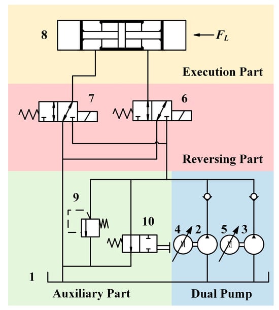
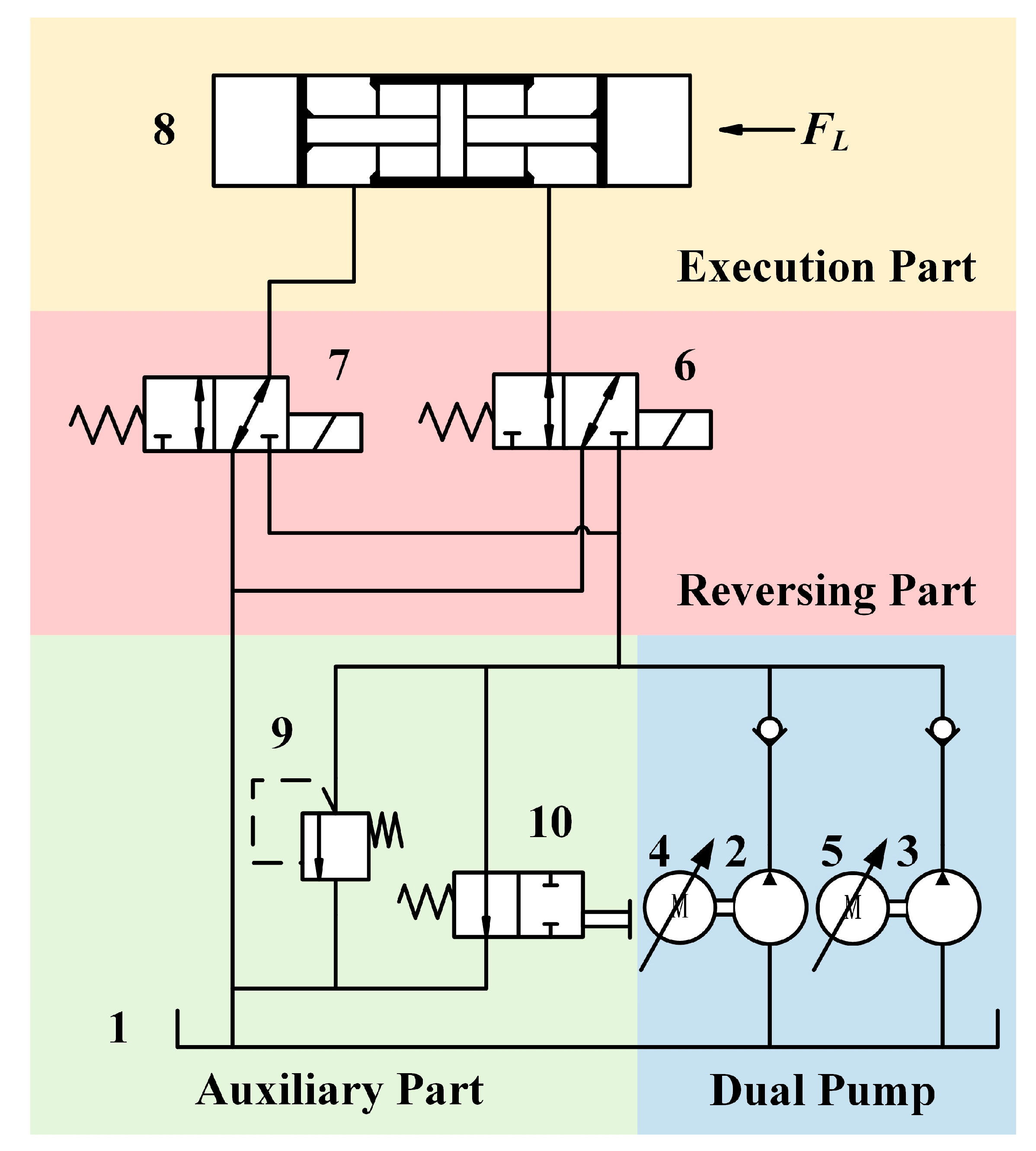
Figure 1 illustrates the “dual-pump–single-cylinder” hydraulic system adopted in this study. It consists of four parts: (1) In the dual-pump part, oil is supplied from the oil tank to the hydraulic pumps with the large-displacement pump responsible for the main supply and the small-displacement pump responsible for precision compensation. The two pumps are controlled by electric motors. (2) In the auxiliary part, a relief valve and a manual unloading valve are used for pressure stabilizing and switching operations. (3) In the reversing part, the cylinder’s inlet and outlet are governed by two independent two/three-way directional valves to realize port switching. (4) In the execution part, the hydraulic cylinder receives external load which is achieved on the test bench through the following method: two relief valves are installed on both cylinder chambers to limit and adjust chamber pressures, and an accumulator is added for oil make-up and pressure buffering, yielding adjustable equivalent load according to experimental requirements.
Figure 1.
Hydraulic system of the thrust cylinder. 1. Oil tank; 2. large-displacement pump; 3. small-displacement pump; 4. electric motor 1; 5. electric motor 2; 6. two/three-way directional valve 1; 7. two/three-way directional valve 2; 8. hydraulic cylinder; 9. relief valve; 10. manual unloading valve.
The hydraulic system presented in this study is not only used for modeling and simulation analysis, but also serves as the core hydraulic mechanism of the test bench employed for experimental validation in the subsequent sections. In summary, the system takes a single hydraulic cylinder as the research object and supplies flow to the cylinder through a dual-pump configuration driven by electric motors. During operation, hydraulic oil is drawn from the oil tank by both the large-displacement pump and the small-displacement pump, and is then directed to the working chamber of the hydraulic cylinder via the corresponding directional valves, thereby providing the required flow input during the start-up phase. Based on the prescribed velocity command, the control system generates the corresponding flow control signals and adjusts the outputs of the two pumps accordingly, enabling the hydraulic cylinder to start smoothly from rest and transition into stable motion.
2.2. Establishment of State-Space Model
The plant is abstracted as a pump-controlled, single-cylinder actuator driven by two pumps in parallel. To improve the accuracy, we model the system in three parts—mechanical dynamics, hydraulic dynamics, and pump-side actuation dynamics—and then assemble them into a nonlinear state-space model with corresponding output equations.
We first model the mechanical dynamics subsystem. The axial force balance of the piston and the kinematic relation is given as [29]
where is the equivalent moving mass, is the piston velocity, is the effective pressure area, is the working-chamber pressure, is the return-side pressure, is the external load, is the viscous damping coefficient, is the Coulomb friction force, and is the piston displacement.
We then model the pressure dynamics. During thrusting, the instantaneous working-chamber volume is expressed as
where is the zero-position equivalent volume, and indicates the sign of volumetric change with displacement. This article takes , which means the volume of the working chamber increases when extended.
Accounting for oil compressibility, inter-chamber leakage, and relief flow when pressure exceeds the valve setting [30], the pressure continuity equation is
where is the effective bulk modulus, are the actual flow rates of the main and auxiliary pumps, is the inter-chamber leakage coefficient, and is the relief flow, with when the relief valve remains closed.
Because the circuit is pump-controlled rather than valve-throttled, we further derive the pump-side actuation dynamics. Considering the electrical and mechanical equations of the electric motor, as well as the load torque of the pump, the relationship between the motor angular velocity and voltage control can be derived as [31]
where the current response is considered fast, so the inductance can be ignored. is the equivalent damping coefficient, is the voltage-to-acceleration gain, and is the pressure load coupling coefficient.
Because the motor shaft is fixedly connected to the pump, the motor angular velocity is the same as the pump. By considering the relationship between the pump flow rate and its rotational angular velocity, the corresponding expression linking the voltage control input to the pump flow rate can be derived as [32]
where is volume efficiency coefficient, and is pump displacement of per revolution. Therefore, the flow rates of the two pumps can be expressed as:
The commended flow rates for dual pumps and determine and through a controller (such as a PID controller), and the expression is shown as follows:
For the overall hydraulic system, we select the state vector and the input vector as follows:
Combining Equations (1)–(11), the nonlinear state-space model of the “dual-pump–single-cylinder” system is yielded as follows:
This means that by setting the expected flow rates of the two pumps reasonably, tracking of hydraulic cylinder displacement can be achieved.
2.3. Identification of Unknown Parameters
To construct a high-fidelity simulation model, the unknown hydraulic parameters must be identified. Specifically, the effective bulk modulus , the inter-chamber leakage coefficient , and the viscous damping coefficient are pivotal to model performance. We adopt a parameter identification approach that iteratively adjusts these parameters so that the model outputs match the experimental measurements under identical operating conditions. By continuously refining the unknowns and minimizing the discrepancy between simulation and experimental data, we obtain optimal estimates that enhance the accuracy and reliability of the state-space model.
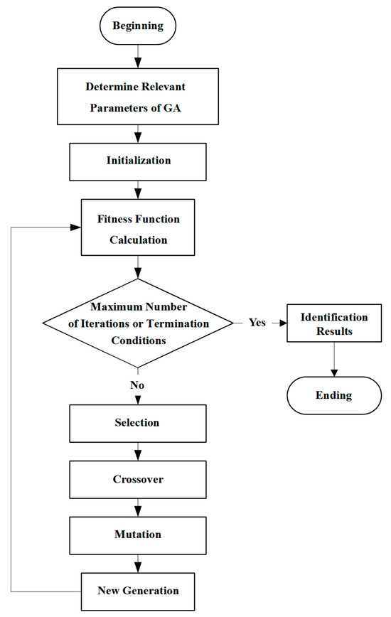
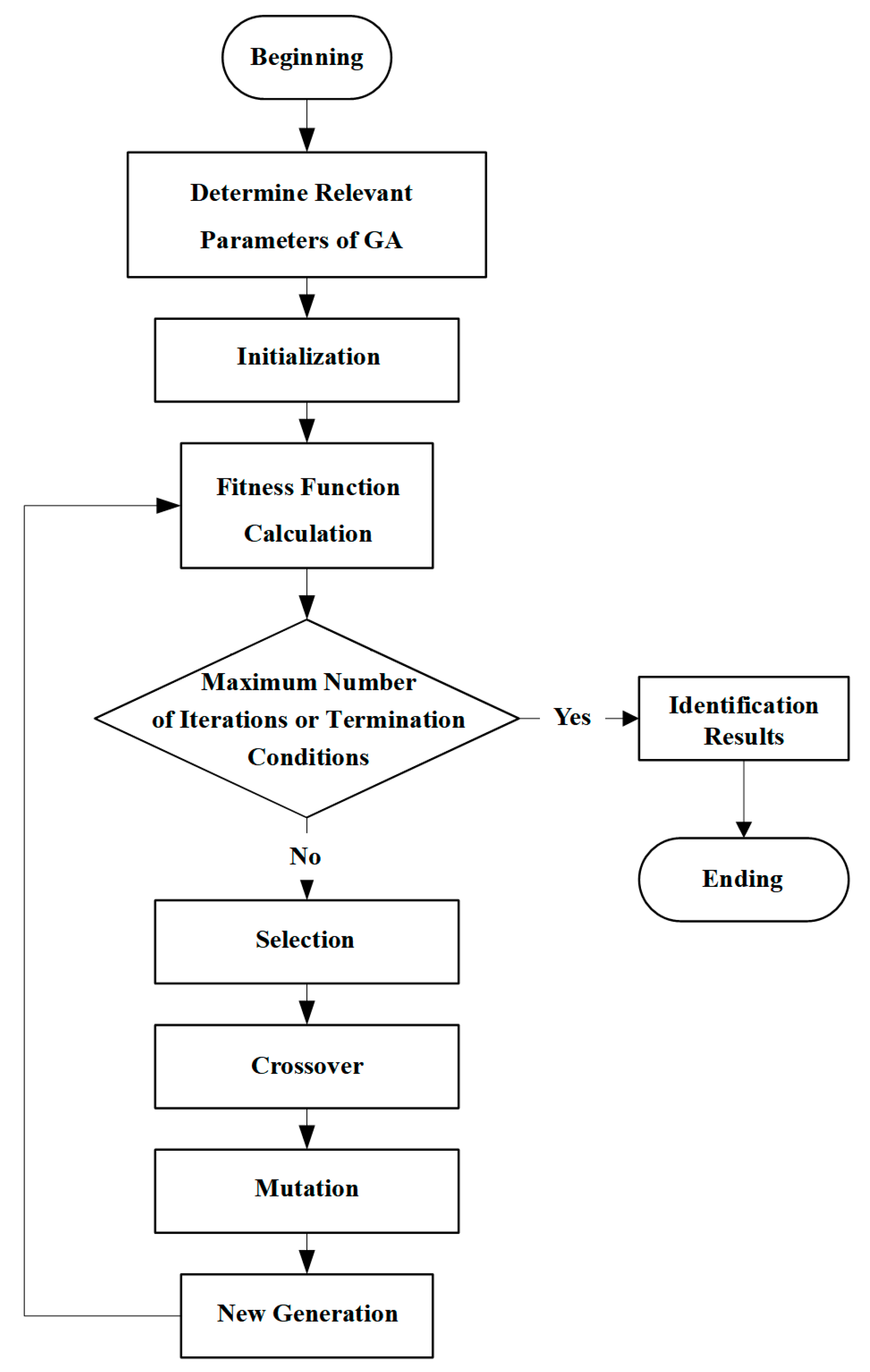
As illustrated in Figure 2, a genetic algorithm (GA) is employed to identify the unknown parameters in the state-space model. The reason for choosing GA is based on the strong nonlinearity and coupling of the pump-controlled hydraulic system, which significantly increases the complexity of the identification problem. Moreover, the cost function is constructed and solved from measured transient responses and does not admit a reliable analytic gradient, while gradient-based methods are typically sensitive to initial guesses and may be trapped in local minima. In contrast, GA performs global search without requiring gradient information and is therefore more robust for identifying coupled parameters under nonlinear dynamics and measurement noise. These considerations make GA a suitable and practical choice for the parameter identification task in this study.
Figure 2.
Working principle of genetic algorithm (GA).
The workflow of GA comprises the following: (1) defining the chromosome encoding, constructing a cost function, and specifying the selection, crossover, and mutation operators; (2) generating an initial population and evaluating individual fitness; (3) if a termination condition (e.g., target accuracy or iteration cap) is satisfied, the best individual is returned and identification terminates; (4) otherwise, selection retains high-fitness individuals as parents, crossover recombines parental chromosomes to form offspring, and mutation perturbs offspring to maintain diversity and prevent premature convergence. The new generation is then re-evaluated, and the process repeats until convergence.
In this study, the encoding method adopts floating-point encoding, the crossover operator is set as single-point crossover with a probability of 0.5, the mutation operator uses adaptive mutation, and the selection operator employs roulette wheel selection. Other GA parameters are set as follows: the maximum number of iterations is 100, the population size is 25, and the number of genes is 5.
The cost function is defined as a weighted sum of squared tracking errors
where denote the displacement, velocity, and pressure errors at the k-th sampling instant, respectively; are weighting coefficients; and is the number of data samples within the identification window. If there is no improvement in the cost function after 10 consecutive iterations (a 1% improvement compared to the previous round), the GA will terminate early.
The experimental data used for parameter identification are obtained from pump-controlled cylinder tests under a single large-displacement pump configuration with a PID controller. During the experiments, the external load is set to 12 MPa and the target velocity is set to 0.05 m/s. To avoid abnormal data at the very initial stage of motion, the experimental data collected from 0.05 s to 20 s are selected for parameter identification with a data acquisition interval of 0.01 s. Based on physical considerations and prior experience, the admissible ranges for the three unknown parameters are summarized in Table 2.
Table 2.
Identification ranges of unknown parameters.
After parameter identification using the GA, the final parameter identification values for three unknown parameters are obtained: effective bulk modulus Pa, inter-chamber leakage coefficient m3/(s·Pa), and viscous damping coefficient (N·s)/m. The obtained parameter values can be input into the state-space model to obtain accurate hydraulic cylinder simulation results. Selecting the simulation data according to the experimental sampling time of 0.01 s, the accuracy indicators (the determination coefficient , the root mean square error , and the mean absolute percentage error , whose definition formulas can refer to [33]) for fitting the simulation results to the experimental results are listed in Table 3.
Table 3.
The fitting accuracy of simulation results.
3. Design and Analysis of the Adaptive Compensation Algorithm
This section develops a small-pump adaptive compensation algorithm under the division of labor of a “large-displacement pump for primary actuation, small-displacement pump for compensation”. The compensation law is driven by displacement error, the high-frequency component of the velocity error, and acceleration error. Its gains are updated online and a lightweight micro-gating factor is further introduced to momentarily limit the compensation value when the large-displacement pump command changes rapidly, thereby preventing over-reaction. This paper proves the stability of the algorithm through the Lyapunov method. Comparative results show that, relative to single-pump control, the dual-pump scheme markedly improves start-up tracking accuracy and responsiveness, shortens the time to reach the target position, avoids noticeable overshoot, and maintains only small fluctuations around the baselines.
3.1. Design of the Adaptive Compensation Algorithm
In the proposed dual-pump scheme, the large-displacement pump with a higher flow capacity is assigned as the primary actuator, while the faster small-displacement pump serves as an auxiliary compensator. The adaptive algorithm adjusts the compensation flow in real time according to error features so as to improve responsiveness without sacrificing stability. As a result, the designed algorithm comprises the following parts: error calculation, gain update, flow compensation calculation, and another auxiliary algorithm.
For error calculation, it includes three aspects: position error, velocity error, and acceleration error. The position error is defined as the difference between the reference position and the measured position, describing the instantaneous displacement deviation; the velocity error is defined as the difference between the reference and measured velocities, characterizing the kinematic mismatch; and the acceleration error is defined as the time derivative of the velocity error. The calculation formulas of three errors are
where is the reference position and is the measured position; is the reference velocity and is the measured velocity.
To prevent low-frequency noise from influencing the compensation channel, the velocity error is decomposed into a low-frequency component and a high-frequency component . The former maintains smoothness, while the latter targets abrupt motion changes for rapid compensation. Their expressions are
where denotes the time constant of the low-frequency filter.
In adaptive algorithms, the selection and adjustment of gains are the core factors that determine algorithm performance. This article chooses displacement error, velocity error, and acceleration error as key parameters that determine the flow rate of the small-displacement pump. Therefore, the reference control value for the small pump compensation flow is
where , , and are the displacement, velocity, and acceleration error gains, which are updated online to accommodate system changes.
In this formula, supplies the instantaneous flow gap by the large-displacement pump; enhances responsiveness to rapidly varying targets while avoiding low-frequency velocity errors that may cause excessive flow of the small pump; and provides feed-forward and damping effects.
The above error gains are updated in real time according to the following criteria to ensure that the small pump’s flow rate can be adaptively adjusted based on the actual tracking situation, thus reducing overshoot, spikes, and minimizing tracking time. The update formulas are shown as
where are the adaptive gain learning rates, which determine the speed of gain updates; are the linear change rates of gain, which restrain the compensation value from being too large, but fluctuate within a certain range; are gain reference values, making gains adaptively fluctuate around these values; is a regularization term that avoids intense updates caused by the presence of extremely small values during the unstable process of the system.
Overall, this adaptive algorithm compensates for large-displacement pump execution error by introducing displacement, velocity, and acceleration errors to determine the small-displacement pump flow input. The small pump’s input is adjusted through algorithms which can accurately and quickly track system changes while maintaining stability within a certain range.
To avoid over-reaction under abrupt operating changes, a micro-gating parameter is applied in the compensation phase. For example, when there is a sudden change in the flow rate of the large pump, there may be an excessive flow compensation reaction of small pump. In this case, the micro-gating parameter can quickly limit the change in compensation signal to avoid system oscillation. The update formula of is
where is the micro-gating time constant. When the speed remains basically unchanged, the micro-gating parameter ; when the speed change exceeds the threshold (target speed changing by more than 20%), the micro-gating parameter quickly switches to 0.75 and gradually returns to 1 with the above updated formula. The final control value for flow compensation of the small pump is as follows:
At the same time, to ensure that the main control effect of the large-displacement pump is maintained, the final control value is limited to ensure that its maximum flow rate does not exceed . The formula is as follows:
It should be noted that the nonlinear state-space model established in Section 2.2 is mainly intended for the subsequent high-fidelity simulation and analysis, so as to accurately reproduce the execution behavior of the hydraulic system. In practical operation, the proposed adaptive compensation algorithm is directly driven by the system states (tracking error, velocity error, and acceleration error) and updates its compensation accordingly. This strategy addresses the problem at the decision level and avoids solving complicated nonlinear inverse dynamics, thereby meeting the requirement of real-time control adjustment.
3.2. Stability Analysis of the Adaptive Compensation Algorithm
At the decision-making level, the large-displacement pump determines the expected flow rate based on the displacement or speed set by the system, while the small-displacement pump calculates the expected flow rate using the adaptive compensation algorithm from Section 3.1 based on the error. At the control level, both the large-displacement and small-displacement pumps employ PID controllers for regulation, and their control loops have been extensively validated for stability. Since the expected flow rate is determined and the control loops are stable, the large-displacement pump loop is closed-loop stable. Therefore, the stability of the hydraulic system described in this paper depends on whether the auxiliary flow generated by the small-displacement pump will cause disturbances to the system. The following Lyapunov equation is selected for stability analysis of the system:
According to the composition of Equation (12), the hydraulic system can be abstracted as
where represent expressions containing state vector, and represents all external disturbances, unmodeled, and other uncertain terms.
By performing a first-order expansion on Equation (27) and combining it with Equation (10), we can obtain
where represent expressions containing the state vector at a certain moment , and represents uncertain terms at a certain moment . Equation (29) can be rewritten as follows:
where is the local slope of the closed-loop error, is the equivalent gain of the small pump input at this operating point, and is the sum errors of all linearized residuals, external load fluctuations, friction changes, and saturation errors.
When is greater than 0, the flow rate of the small pump is greater than 0 and the closed-loop system of the large pump is affected by the PID controller (with pre-set parameters) to increase the flow rate value, so it must be in an error convergence state; when is less than 0, the closed-loop system of the large pump is affected by the PID controller to reduce the flow rate. According to Equations (19)–(23), the changing rate of the small-displacement pump flow rate is extremely small at this time, so the overall system is in an error convergence state. Therefore, must be greater than 0. Due to the certainty and absence of rapid changes in the hydraulic system, external disturbances and modeling errors are bounded ().
According to the following theorem (), selecting , , and yields the following inequality:
By selecting , in the same way, the following inequality can be obtained:
Combining Formulas (30)–(32), the following formula can be obtained:
Due to the existence of upper bounds on the last two terms of the inequality in Equation (33), the system is stable when the displacement error increases (); when the error is less than this value, the stability of the system cannot be determined, but at this time, the error is bounded. Therefore, in summary, the system is stable.
3.3. Verification of the Adaptive Compensation Algorithm
Before verifying the compensation effects of the dual-pump scheme, the control structure and settings are explicitly clarified. In this study, the control inputs are the commanded flow rates and of the large-displacement pump and the small-displacement pump, whereas the outputs are the cylinder displacement and velocity. The displacement and velocity references are dynamically consistent, and they are pre-zeroed before each experiment and recorded at the same frequency (once every 0.01 s). To ensure a fair comparison of the influence of flow-compensation mechanisms, both pumps are regulated using standard PID controllers. The PID gains were tuned by trial and error in simulation until a compromise between overshoot and settling time was obtained under the nominal load condition. The final PID parameters are set to the following: Kp1 = 800, Ki1 = 0.10, and Kd1 = 0.001 for the large-displacement pump; Kp2 = 550, Ki2 = 0.003, and Kd2 = 0.001 for the small-displacement pump. In addition, due to the inherent start-up characteristic of pumps, slow flow response during the start-up phase cannot be effectively optimized by introducing algorithms such as pressure feedback or adaptive control. Therefore, a PID controller is sufficiently representative and meets accuracy requirements.
For all simulations, the external load acting on the cylinder is fixed at 12 kN, consistent with the measured equivalent load on the test bench. All hydraulic, geometric, and dynamic parameters are identical to those of the experimental system, as listed in Table 4, so that the controller performance is assessed under realistic operating conditions. The key parameter values of the adaptive algorithm used in this study are summarized in Table 5. To evaluate the effectiveness of the proposed adaptive compensation algorithm, we compare the tracking performance of a single-pump (large-displacement pump) scheme against the dual-pump cooperative scheme in 0–20 s. A high-fidelity simulation model is constructed on the basis of the state-space model and the identified parameters, and the two control strategies are tested under a range of start-up speed commands.
Table 4.
Main known hydraulic system parameter values.
Table 5.
Key parameter values for the adaptive compensation algorithm.
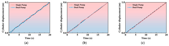
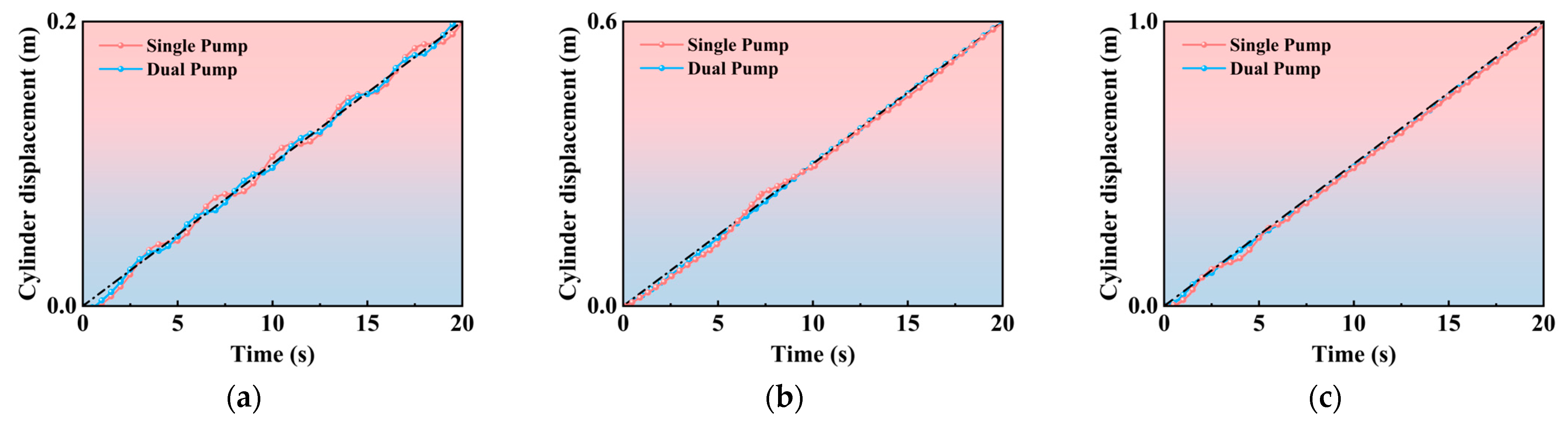
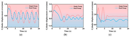
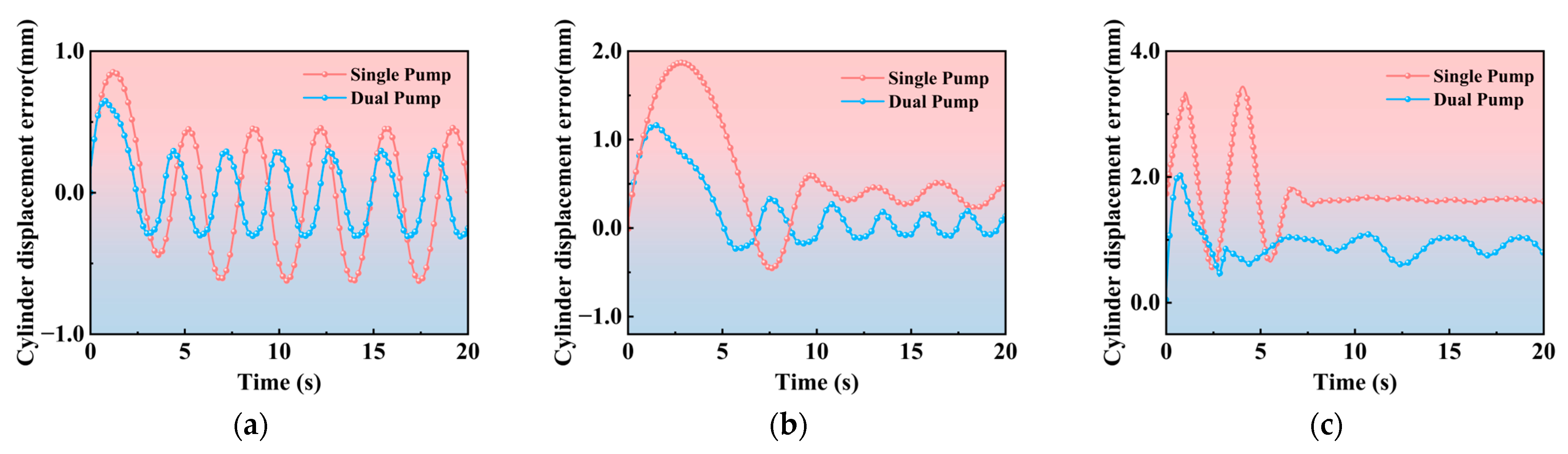
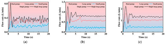
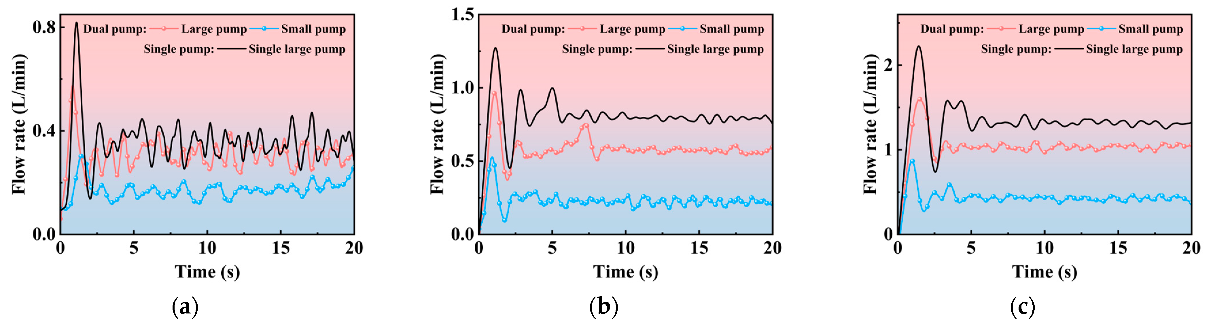
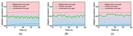
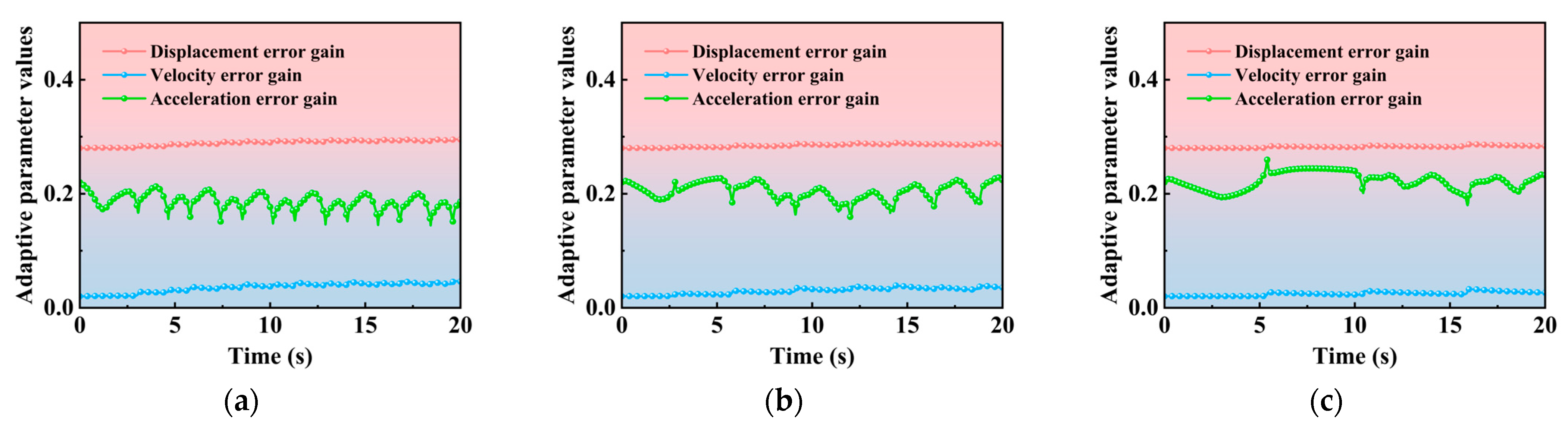
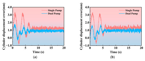
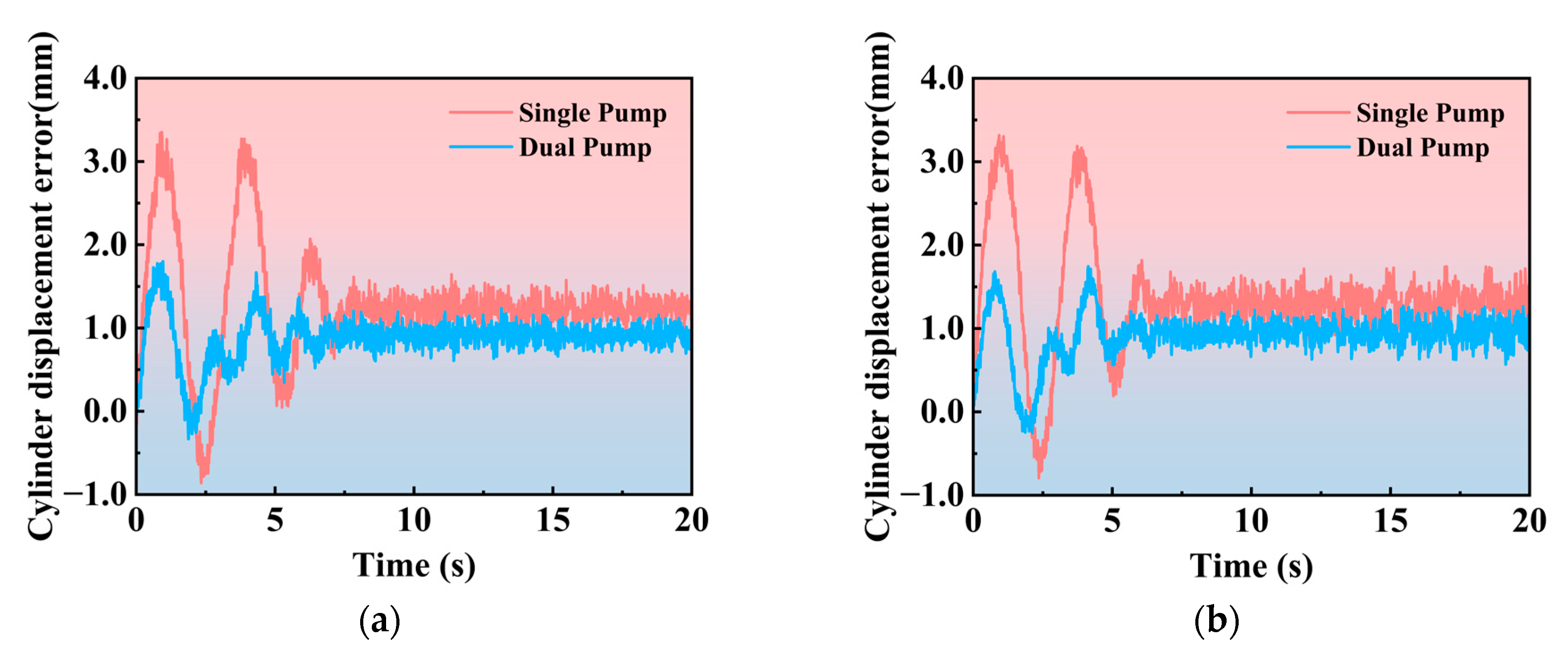
Figure 3 and Figure 4 illustrate the tracking errors at representative target start-up velocity of 0.01 m/s, 0.03 m/s, and 0.05 m/s. Obviously, the adaptive compensation algorithm markedly improves start-up tracking accuracy and once the expected position is reached, the hydraulic cylinder can be accurately controlled near it. As shown in Figure 5, the flow of the small-displacement pump is instantly boosted during the start-up phase and then quickly suppressed. This behavior indicates that the adaptive gains yield highly efficient compensation: in the early stage, velocity and acceleration errors accelerate the flow compensation to achieve fast catch-up; later, as the actual velocity and acceleration exceed their references to reduce displacement error, these terms become negative and drive the small pump’s flow downward, preventing overshoot. During the steady-state phase, as the closed-loop error signal of the large-displacement pump flow control loop approaches zero, the compensation flow provided by the auxiliary pump correspondingly becomes stable. At this stage, the flow outputs of the main pump and the auxiliary pump reach a dynamic balance. As shown in Figure 5, the ratio of the main pump flow to the auxiliary pump flow in the steady-state phase is approximately in the range of 2~3. As shown in Figure 6, the adaptive parameters fluctuate throughout the entire process but are controlled within a certain range, confirming that the linear drift terms in Equations (20)–(23) effectively constrain the updates.
Figure 3.
Displacement tracking of two control algorithms: (a) velocity = 0.01 m/s; (b) velocity = 0.03 m/s; (c) velocity = 0.05 m/s. Note: For clarity, the displacement tracking response is visually magnified by a factor of 10 in this figure (display only). All statistics are calculated using the original error data, and the detailed error curve is shown in Figure 4.
Figure 4.
Displacement tracking errors of two control algorithms: (a) velocity = 0.01 m/s; (b) velocity = 0.03 m/s; (c) velocity = 0.05 m/s.
Figure 5.
Changes in flow rate of two control algorithms: (a) velocity = 0.01 m/s; (b) velocity = 0.03 m/s; (c) velocity = 0.05 m/s.
Figure 6.
Changes in adaptive parameter values: (a) velocity = 0.01 m/s; (b) velocity = 0.03 m/s; (c) velocity = 0.05 m/s.
4. Experimental Validation of the Adaptive Compensation Algorithm
4.1. Experimental Setup and Comparative Validation
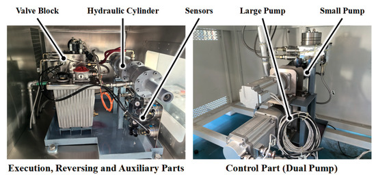
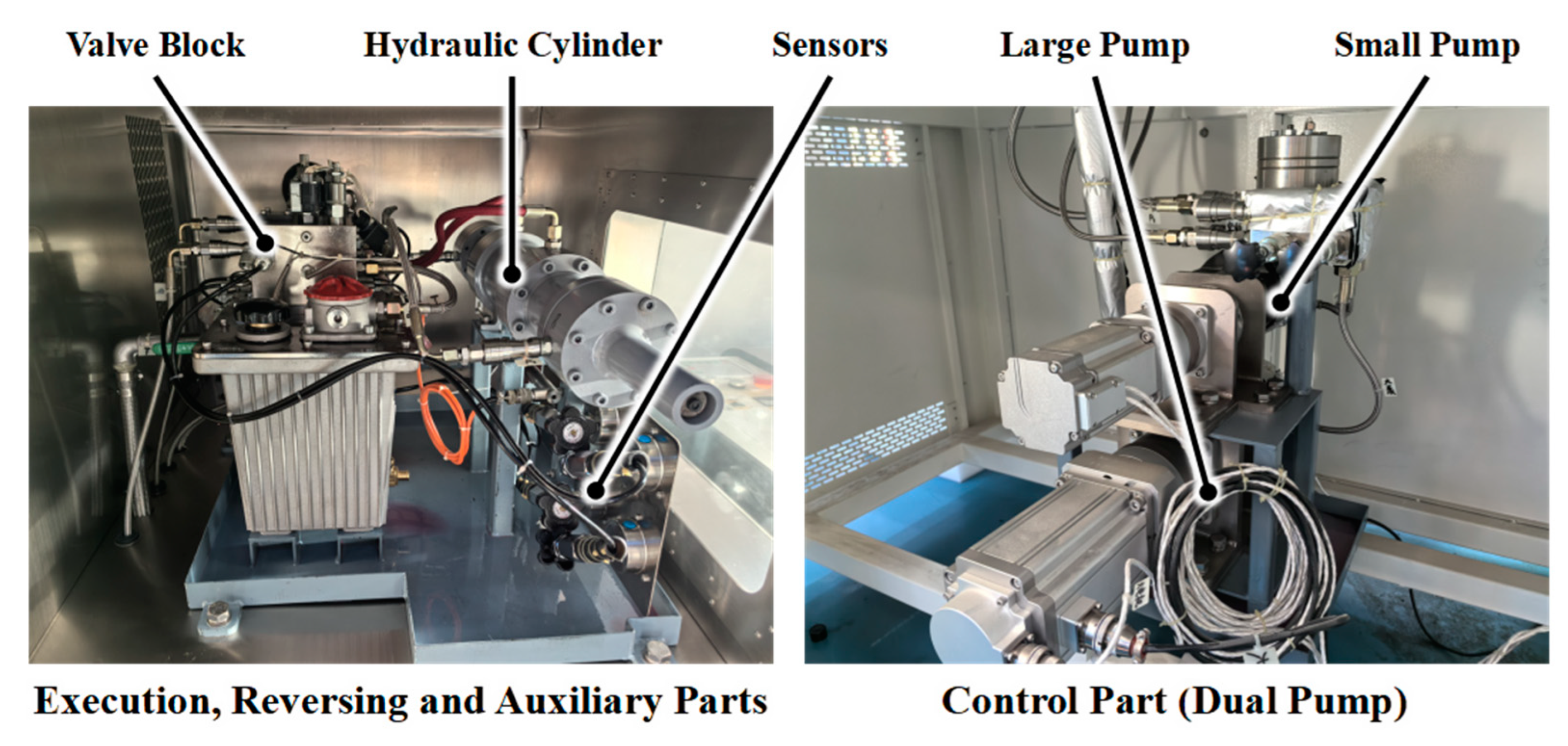
As shown in Figure 7, the experimental equipment follows the same architecture as the previously described “dual-pump–single-cylinder” hydraulic system. The large-displacement pump and the small-displacement pump are integrated and jointly draw the required hydraulic flow from the oil tank. Their outlets are connected to a valve block that integrates multiple hydraulic functions, including directional control, pressure relief, and unloading, thereby enabling functions such as directional switching, pressure protection, and emergency stopping. The valve block is further connected to the hydraulic cylinder to supply the required flow for actuation. To realize the detection capability, a set of sensors is additionally installed to monitor key parameters in real time, including the hydraulic cylinder displacement, system pressure, and flow rate. The specifications of the selected sensors are summarized in Table 6.
Figure 7.
Dual-pump control experimental equipment.
Table 6.
Selection of sensors for the test bench.
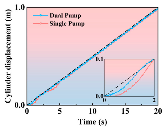
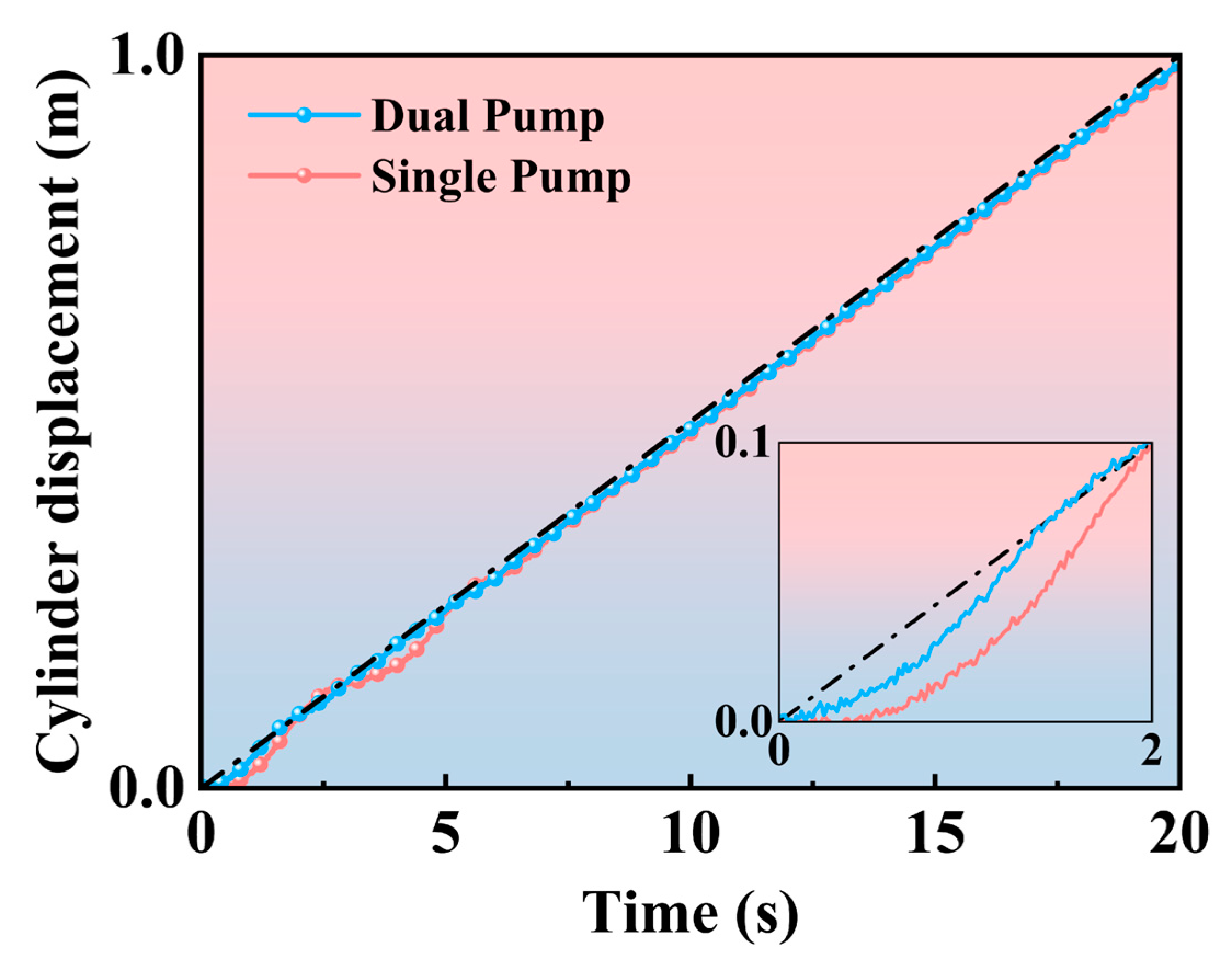
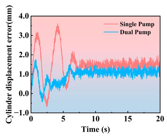
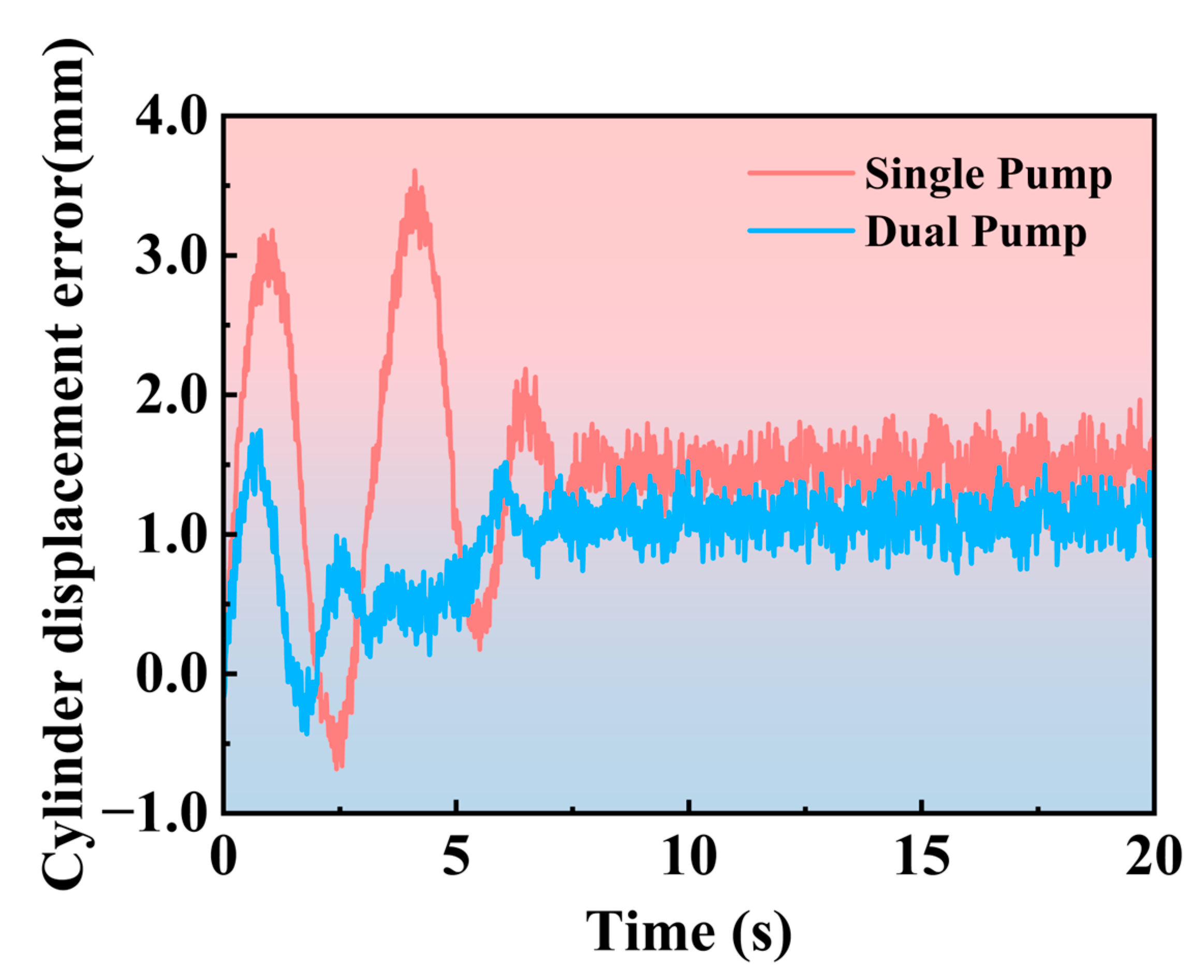
At a target start-up velocity of 0.05 m/s, the proposed small-pump adaptive compensation algorithm was then validated on this equipment. As shown in Figure 8 and Figure 9, the maximum displacement error during the start-up phase is significantly reduced from 3.5 mm to 1.7 mm when the adaptive compensation is applied. Meanwhile, system tracking speed is markedly improved with the position error recovery time reduced by 1 s, corresponding to a 20% improvement over the single-pump scheme.
Figure 8.
Displacement tracking of two control algorithms on the test bench. Note: For clarity, the displacement tracking response is visually magnified by a factor of 10 in this figure (display only). All statistics are calculated using the original error data, and the detailed error curve is shown in Figure 9.
Figure 9.
Displacement tracking errors of two control algorithms on the test bench.
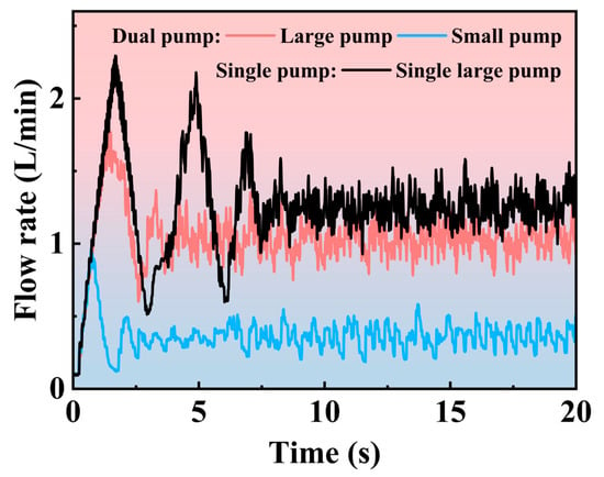
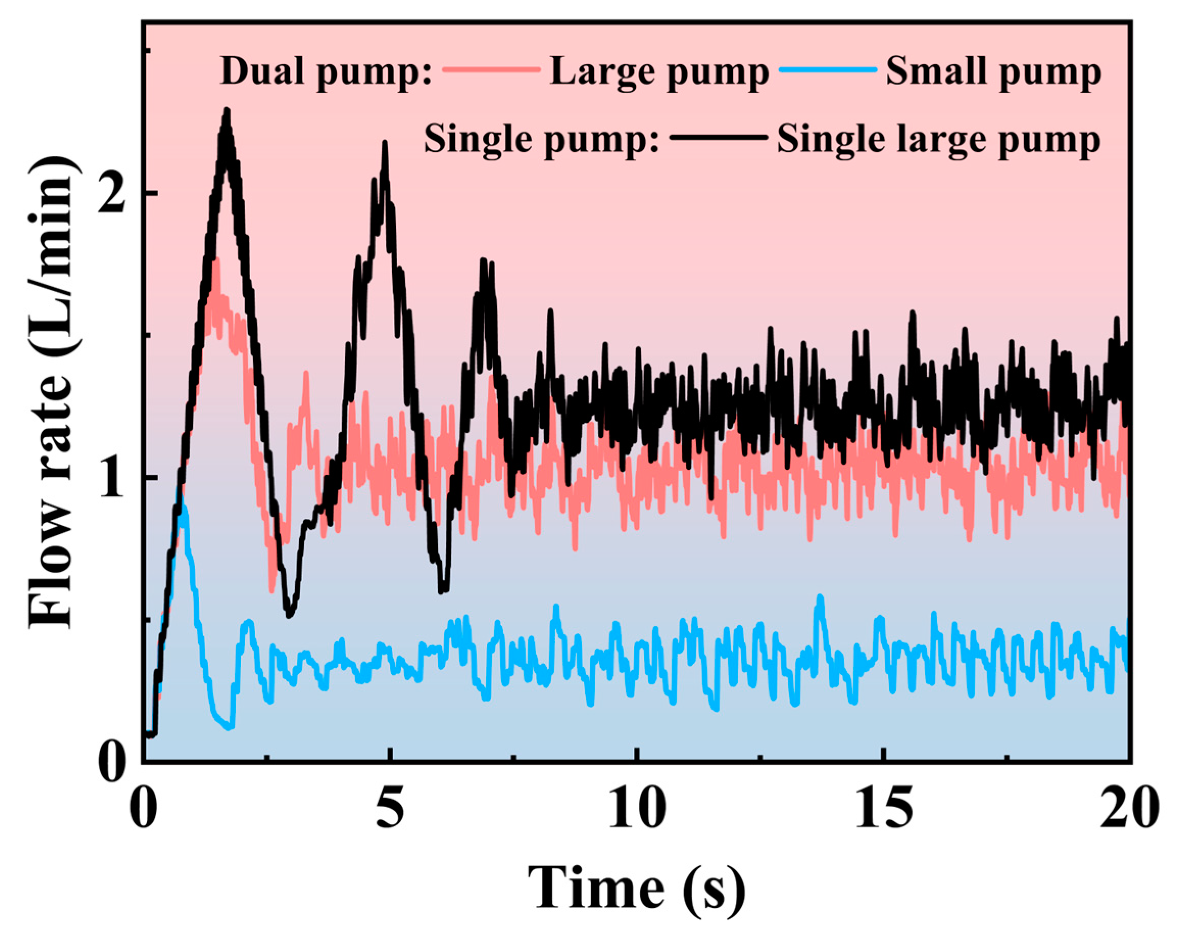
Figure 10 presents the flow rate of dual pumps on the test bench under the adaptive compensation algorithm. In comparison with Figure 5, the overall flow allocation and fluctuation trends are consistent with the simulation results, reinforcing the prior analysis: the adaptive small-pump flow yields substantial gains in start-up rapidity, while the inclusion of a negative linear drift term and the micro-gating parameter suppresses abrupt transients, ensuring stability without overshoot. Overall, the small-pump adaptive compensation algorithm provides notable improvements in fast transient response and maintains stability. The experimental results further demonstrate the effectiveness of the adaptive compensation algorithm, indicating that it can be applied to real-world hydraulic systems.
Figure 10.
Changes in flow rate of dual pumps on the test bench.
4.2. Further Experimental Analysis
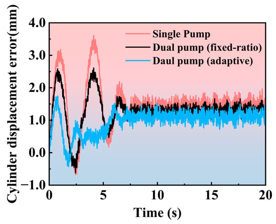
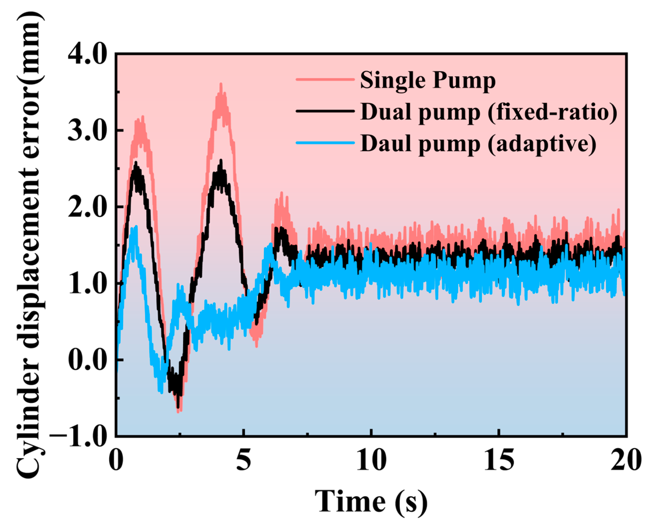
To distinguish the effect of introducing an auxiliary pump from that of the proposed adaptive compensation and micro-gating strategy, an additional baseline based on the same dual-pump hardware configuration is considered. In this baseline, the main pump, owing to its higher flow capacity, is assigned to track 60% of the target flow, while the auxiliary pump is set to track the remaining 40%. During this process, the small-displacement pump does not perform any adaptive adjustment based on tracking errors or system states, and its output remains strictly governed by the fixed flow allocation. This rule-based strategy represents a typical dual-pump control approach without adaptive compensation.
As shown in Figure 11, the tracking error obtained using the conventional dual-pump control strategy is larger than that achieved by the proposed auxiliary-pump adaptive compensation method. Although the conventional method provides a certain improvement compared with the single-pump control scheme, the extent of this improvement remains rather limited. These results indicate that the performance enhancement observed in the proposed method cannot be attributed solely to the introduction of an auxiliary pump. Instead, it plays a critical role in improving system performance and achieving higher tracking accuracy.
Figure 11.
Displacement tracking errors of different dual-pump schemes.
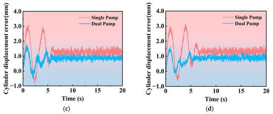
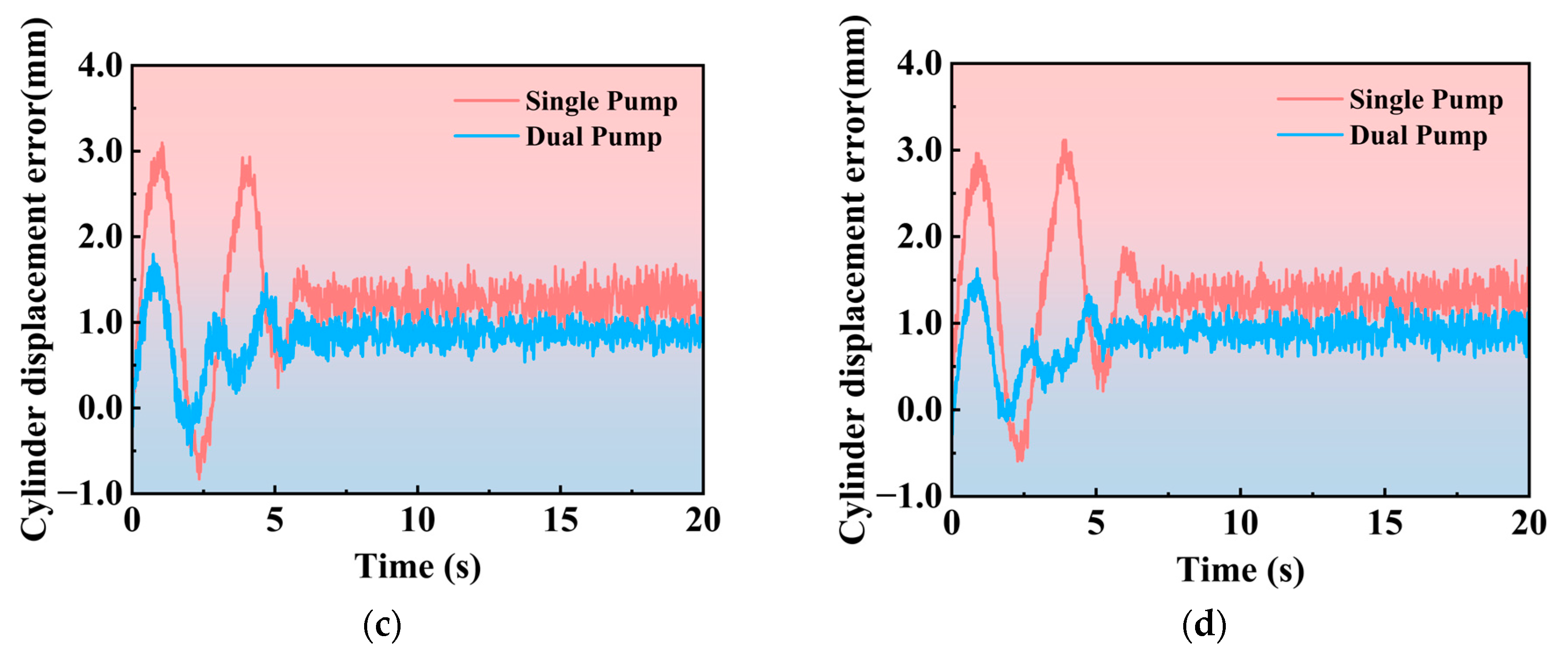
To evaluate the performance of the adaptive compensation algorithm under different external load conditions, this study further investigates the influence of load variations on the displacement tracking error. Specifically, comparative experiments were conducted with external loads of 7, 8, 9, and 10 kN, and the resulting displacement tracking errors are presented in Figure 12. It can be observed that, despite changes in the load value, the overall shape and trend of the error curves remain largely consistent: the errors exhibit similar convergence behavior during the transient regulation stage, and the steady-state fluctuation amplitudes stay within the same order of magnitude, without noticeable drift or amplified oscillations as the load increases.
Figure 12.
Displacement tracking errors in different external loads: (a) external load = 10 kN; (b) external load = 9 kN; (c) external load = 8 kN; (d) external load = 7 kN.
For quantitative comparison during 0–20 s, the maximum , minimum , mean , and standard deviation of the displacement errors under different loads are summarized in Table 7, the definitions of which are shown in Equations (34)–(37). As indicated by the results, the maximum, minimum, and mean errors are nearly identical across the tested load cases, and the differences in standard deviation are also marginal, suggesting that the dispersion of the error distribution is insensitive to external load variations. Overall, the proposed algorithm maintains stable and consistent tracking performance within the considered external load range, demonstrating favorable load adaptability.
Table 7.
Evaluation metrics of different external loads and system architectures.
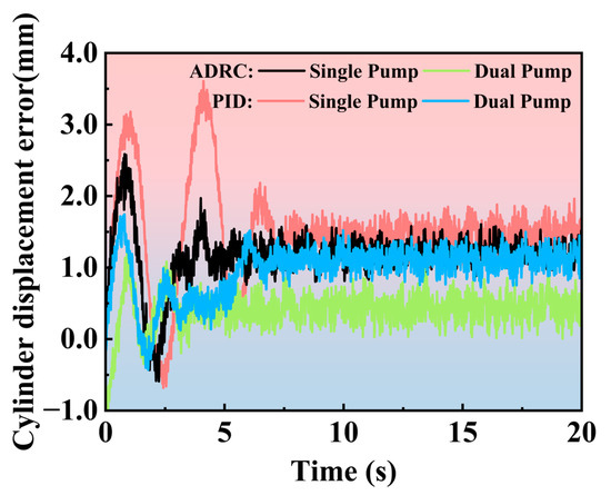
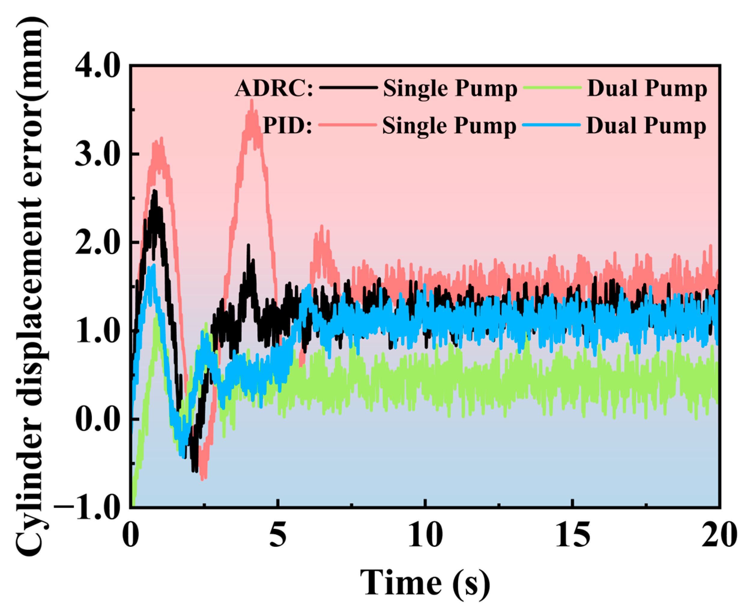
Finally, the PID controller was replaced with an active disturbance rejection control (ADRC) controller to compare the performance of the proposed small-pump adaptive compensation algorithm under different controllers. The controller parameters are listed in Table 8. As shown in Figure 13, when comparing single-pump and dual-pump control results under both controllers, the ADRC controller achieves higher tracking accuracy than the PID controller, which is mainly attributed to the state/disturbance observer for uncertainty compensation. Moreover, under ADRC, the dual-pump configuration further improves the control accuracy during the start-up phase, even though the advanced controller already provides relatively better baseline performance. Intuitively, one may view the inherent capability of the hydraulic system as an “80 points” potential; with a basic controller, only about “70 points” of this potential can be realized. By introducing the proposed small-pump compensation, the achievable system performance is elevated to around “90 points” so that the controller can deliver “80 points” or more in practice. These results indicate that the proposed dual-pump compensation strategy improves the system-level performance of the hydraulic cylinder and effectively enhances start-up tracking accuracy.
Table 8.
Control parameters of the ADRC controller.
Figure 13.
Displacement tracking errors of two controllers in two control algorithms.
5. Conclusions and Outlook
With respect to the problem and system-level objective, this study addresses the insufficient start-up tracking accuracy in a TBM propulsion pump-controlled cylinder system and seeks to improve transient performance at the system level. Regarding modeling and theoretical support, a nonlinear state-space model is established for high-fidelity simulation and analysis; key unknown parameters are identified using experimental data, and the stability of the adaptive algorithm is analyzed. From the perspective of methodology, a “dual-pump–single-cylinder” architecture is adopted, in which the large-displacement pump supplies the basic flow demand and the auxiliary pump provides error-driven adaptive compensation with a micro-gating mechanism to regulate transient actuation. For verification and generality, the proposed approach is validated through simulations and experiments, and extended experimental tests are conducted to evaluate the compensation algorithm effectiveness, its adaptability under different operating conditions, and its performance under different controllers. Overall, the results consistently indicate reduced start-up tracking error, faster transient convergence, and robustness across varying loads and control settings.
In the future, we will extend the approach to multi-cylinder coordination with constraints, augment it with online parameter identification and energy-efficiency co-optimization, and conduct practical engineering applications. The goal is to develop a systematic flow compensation method that enhances rapidity and stability under complex geology and frequent speed transitions.
Author Contributions
S.Y.: writing—original draft, visualization, validation, software, methodology, formal analysis, data curation, conceptualization. D.H. (Dong Han): writing—review and editing, supervision, methodology, conceptualization. L.J. (Lijie Jiang) and L.J. (Lianhui Jia): writing—review and editing, validation, software, formal analysis. Z.Z., X.T. and H.Y.: writing—review and editing, supervision, conceptualization. D.H. (Dongming Hu): writing—review and editing, resources, project administration, funding acquisition. All authors have read and agreed to the published version of the manuscript.
Funding
This work received support from the Key Science and Technology Program of the Ministry of Emergency Management of China (Grant No. 2025EMST130301), the National Natural Science Foundation of China (No. 52475075), and the National Natural Science Foundation of China (No. 52575056).
Institutional Review Board Statement
Not applicable.
Informed Consent Statement
Not applicable.
Data Availability Statement
The original contributions presented in this study are included in the article. Further inquiries can be directed to the corresponding author.
Acknowledgments
The authors would like to thank the anonymous reviewers for their valuable suggestions.
Conflicts of Interest
The authors Lijie Jiang and Lianhui Jia were employed by the company China Railway Engineering Equipment Group Co., Ltd. The remaining authors declare that the research was conducted in the absence of any commercial or financial relationships that could be construed as a potential conflict of interest.
References
- Xu, Z.H.; Wang, W.Y.; Lin, P.; Nie, L.C.; Wu, J.; Li, Z.M. Hard-Rock TBM Jamming Subject to Adverse Geological Conditions: Influencing Factor, Hazard Mode and a Case Study of Gaoligongshan Tunnel. Tunn. Undergr. Space Technol. 2021, 108, 103683. [Google Scholar] [CrossRef] [Scilit]
- Wang, Z.; Jiang, Y.; Shao, X.; Liu, C. On-Site Measurement and Environmental Impact of Vibration Caused by Construction of Double-Shield TBM Tunnel in Urban Subway. Sci. Rep. 2023, 13, 17689. [Google Scholar] [CrossRef] [Scilit] [PubMed]
- Kong, S.-M.; Byun, Y.; Choi, S.-I.; Kim, C.-Y.; Lee, S.-W. A Study of Vibration Reduction Effects of TBM and NATM Parallel Construction Methods According to Tunnel Depth and Size. Appl. Sci. 2023, 13, 3492. [Google Scholar] [CrossRef] [Scilit]
- Wu, W.; Gong, G.; Huan, Q.; Zhou, X.; Chen, Y.; Peng, X. Investigation into the Electrohydraulic Synchronous Motion Control of a Thrust System for a Tunnel Boring Machine. Machines 2022, 10, 119. [Google Scholar] [CrossRef] [Scilit]
- Zheng, Z.; Luo, K.; Tan, X.; Jia, L.; Xie, M.; Xie, H.; Jiang, L.; Gong, G.; Yang, H.; Han, D. Autonomous Steering Control for Tunnel Boring Machines. Autom. Constr. 2024, 159, 105259. [Google Scholar] [CrossRef] [Scilit]
- Wang, R.; Zhang, L. A Theoretical Method and Model for TBM Tunnelling Trajectory Adjustment. Appl. Sci. 2023, 13, 10876. [Google Scholar] [CrossRef] [Scilit]
- Guan, C.; Pan, S. Adaptive Sliding Mode Control of Electro-Hydraulic System with Nonlinear Unknown Parameters. Control Eng. Pract. 2008, 16, 1275–1284. [Google Scholar] [CrossRef] [Scilit]
- Qiu, Z.; Hu, S.; Liang, X. Disturbance Observer Based Adaptive Model Predictive Control for Uncalibrated Visual Servoing in Constrained Environments. ISA Trans. 2020, 106, 40–50. [Google Scholar] [CrossRef] [Scilit]
- Gu, W.; Yao, J.; Yao, Z.; Zheng, J. Output Feedback Model Predictive Control of Hydraulic Systems with Disturbances Compensation. ISA Trans. 2019, 88, 216–224. [Google Scholar] [CrossRef] [Scilit]
- Zhang, Y.; Li, Y.; Li, G.; Li, G.; Wang, B. Simulation Analysis of MPC Control of Electro-Hydraulic Position Servo Systems. Chin. Hydraul. Pneum. 2024, 48, 38–45. [Google Scholar] [CrossRef]
- Yin, L.; Su, X. Research on Control of Hydraulic Position Tracking System Based on Event Triggering and Disturbance Observer. Processes 2025, 13, 1725. [Google Scholar] [CrossRef] [Scilit]
- Quan, Z.; Quan, L.; Zhang, J. Review of Energy Efficient Direct Pump Controlled Cylinder Electro-Hydraulic Technology. Renew. Sustain. Energy Rev. 2014, 35, 336–346. [Google Scholar] [CrossRef] [Scilit]
- Alle, N.; Hiremath, S.S.; Makaram, S.; Subramaniam, K.; Talukdar, A. Review on Electro Hydrostatic Actuator for Flight Control. Int. J. Fluid Power 2016, 17, 125–145. [Google Scholar] [CrossRef] [Scilit]
- Chao, Q.; Zhang, J.; Xu, B.; Huang, H.; Pan, M. A Review of High-Speed Electro-Hydrostatic Actuator Pumps in Aerospace Applications: Challenges and Solutions. J. Mech. Des. 2019, 141, 050801. [Google Scholar] [CrossRef] [Scilit]
- Takahashi, N.; Kondo, T.; Takada, M.; Masutani, K.; Okano, S.; Tsujita, M. Development of Prototype Electro-Hydrostatic Actuator for Landing Gear Extension and Retraction System. Proc. JFPS Int. Symp. Fluid Power 2008, 2008, 165–168. [Google Scholar] [CrossRef] [Scilit]
- Du, S.; Zhou, J.; Hong, J.; Zhao, H.; Ma, S. Application and Progress of High-Efficiency Electro-Hydrostatic Actuator Technology with Energy Recovery: A Comprehensive Review. Energy Convers. Manag. 2024, 321, 119041. [Google Scholar] [CrossRef] [Scilit]
- Kumar, M. A Survey on Electro Hydrostatic Actuator: Architecture and Way Ahead. Mater. Today Proc. 2021, 45, 6057–6063. [Google Scholar] [CrossRef] [Scilit]
- Yuan, C.; Pan, M.; Plummer, A. A Review of Switched Inertance Hydraulic Converter Technology. J. Dyn. Syst. Meas. Control 2020, 142, 050801. [Google Scholar] [CrossRef] [Scilit]
- Scheidl, R.; Woess, D. A Combined Multi-Pressure Switched Inertance Hydraulic Control Concept of a Differential Cylinder. MM Sci. J. 2022, 2022, 5775–5782. [Google Scholar] [CrossRef] [Scilit]
- Kogler, H. Digital Hydraulic Transformer Concepts for Energy-Efficient Motion Control. Actuators 2025, 14, 54. [Google Scholar] [CrossRef] [Scilit]
- Fang, D.; Jia, G.; Wang, J.; Wu, G.; Cao, L.; Zhang, J. Design and Analysis of a Novel Rotary Inertance Hydraulic Converter with the Continuous Controlling Turntable. Trans. Can. Soc. Mech. Eng. 2024, 48, 459–468. [Google Scholar] [CrossRef] [Scilit]
- Annaz, F.Y.; Kaluarachchi, M.M. Progress in Redundant Electromechanical Actuators for Aerospace Applications. Aerospace 2023, 10, 787. [Google Scholar] [CrossRef] [Scilit]
- Li, Y.; Pan, Y.; Zhang, L. Physics-Guided Deep Learning for Driving Force Estimation in Synchronous Tunnel Boring Machines under Missing Cylinders. Autom. Constr. 2024, 161, 105339. [Google Scholar] [CrossRef] [Scilit]
- Lin, P.; Ji, A.; Zhou, Y.; Zhang, L.; Tiong, R.L.K. Automated Position Control of Tunnel Boring Machine during Excavation Using Deep Reinforcement Learning. Appl. Soft Comput. 2024, 167, 112234. [Google Scholar] [CrossRef] [Scilit]
- Wang, M.; Tian, C.; Yang, W.; Zhou, Z.; Bai, Y.; Song, X.; Geng, Y. Study on the Information Evolution Law of Water-Resistant Rock Mass during Fault Water and Mud Inrush in TBM Tunnels. KSCE J. Civ. Eng. 2024, 28, 4088–4099. [Google Scholar] [CrossRef] [Scilit]
- Peng, J.-R.; Zhou, H.; Hao, J.-Y.; Wang, Y.-N. Vibration Reduction Technique of Shield Construction in Water-Rich Karst Strata. J. Infrastruct. Intell. Resil. 2024, 3, 100111. [Google Scholar] [CrossRef] [Scilit]
- Wang, S.; Wang, L.; Wu, L.; Li, X. A Jamming Risk Warning Model for TBM Tunnelling Based on Bayesian Statistical Methods. Sci. Rep. 2025, 15, 35452. [Google Scholar] [CrossRef] [Scilit]
- Jiang, L.; Zheng, Z.; Zhu, K.; Gong, G.; Yang, H.; Han, D. Novel Dual Parallel-Connected-Pump Hydraulic System and Error Allocation Strategy for Segment Assembly. Machines 2024, 12, 913. [Google Scholar] [CrossRef] [Scilit]
- Rahmat, M.F.; Husain, A.R.; Ishaque, K.; Sam, Y.M.; Ghazali, R.; Rozali, S.M.; Has, Z. Modeling and Controller Design of an Industrial Hydraulic Actuator System in the Presence of Friction and Internal Leakage. Int. J. Phys. Sci. 2011, 6, 3502–3517. [Google Scholar] [CrossRef]
- Zhang, K.; Zhang, J.; Gan, M.; Zong, H.; Wang, X.; Huang, H.; Su, Q.; Xu, B. Modeling and Parameter Sensitivity Analysis of Valve-Controlled Helical Hydraulic Rotary Actuator System. Chin. J. Mech. Eng. 2022, 35, 66. [Google Scholar] [CrossRef] [Scilit]
- Belloli, D.; Previdi, F.; Savaresi, S.M.; Cologni, A.; Zappella, M. Modeling and Identification of an Electro-Hydrostatic Actuator. IFAC Proc. 2010, 43, 620–625. [Google Scholar] [CrossRef] [Scilit]
- Zhang, Y.; Gong, G.; Yang, H.; Chen, Y.; Chen, G. Towards Autonomous and Optimal Excavation of Shield Machine: A Deep Reinforcement Learning-Based Approach. J. Zhejiang Univ.-Sci. A 2022, 23, 458–478. [Google Scholar] [CrossRef] [Scilit]
- Samaei, M.; Ranjbarnia, M.; Nourani, V.; Zare Naghadehi, M. Performance Prediction of Tunnel Boring Machine through Developing High Accuracy Equations: A Case Study in Adverse Geological Condition. Measurement 2020, 152, 107244. [Google Scholar] [CrossRef] [Scilit]

Disclaimer/Publisher’s Note: The statements, opinions and data contained in all publications are solely those of the individual author(s) and contributor(s) and not of MDPI and/or the editor(s). MDPI and/or the editor(s) disclaim responsibility for any injury to people or property resulting from any ideas, methods, instructions or products referred to in the content. |
© 2026 by the authors. Licensee MDPI, Basel, Switzerland. This article is an open access article distributed under the terms and conditions of the Creative Commons Attribution (CC BY) license.