


Abstract
The application of plain bearings has become very famous in planetary gear stages in recent years. To improve load-carrying capacity, this study investigates a design method for axial profiling in which a sixth-order polynomial is iteratively derived from the curve of local minimum film thickness for each axial grid position. Two load cases with specific bearing loads of 12.0 MPa and 6.0 MPa at 0.5 m/s are considered for profile design. Calculation results and computational effort of strategies assuming rigid or elastic geometries during the optimization are compared. Results indicate that the consideration of deformation is already necessary in the design phase and a maximization of minimum film thickness leads to much higher load-carrying capacity than the minimization of the maximum film pressure. Furthermore, the impact of the lube oil pocket position on oil flow rate is experimentally and theoretically investigated to identify the optimization potential of this parameter. Results show that the oil flow varies by the factor of three if the lube oil pocket is shifted incrementally over an angular span of 180° outside the load zone. The results and possible extensions are critically discussed under the consideration of practically relevant restrictions in mechanically highly loaded planetary gearboxes.
1. Introduction
Journal bearings are increasingly used in slow-running, highly loaded tribological systems, where ensuring functional reliability under diverse operating conditions requires careful consideration of bearing design, as design parameters strongly influence operational performance. Planetary gear systems exhibit a power density substantially higher than that of conventional spur gear transmissions. This property allows for highly efficient transformation of rotational speed and torque within a compact design envelope. Nevertheless, these advantages are frequently accompanied by increased design intricacy, necessitating intensified research and development efforts. Given their significant potential to enhance efficiency and promote more sustainable resource utilization—particularly through the implementation of journal-bearing planetary gears—the refinement of theoretical models aimed at improving robustness and efficiency is of considerable economic and scientific importance. In conjunction with this, comprehensive experimental validation is essential for ensuring the reliability and applicability of these models.
Axial profiling of planetary pins is essential to ensure the functionality and operational reliability of journal bearings and represents a key design parameter for reducing localized peak loads at bearing edges. For contact partners subject to high edge loading, the implementation of axial crowning is an established design method for decreasing local maximum contact intensity. Although several design approaches for profiling exist, detailed investigations of individual methods have not yet been conducted sufficiently. Improper crowning profiles can lead to inadequate lubrication and severe bearing damage, potentially resulting in failure of the entire system. Typical applications of such crowning include rolling element bearings and gear tooth flanks. Johns and Gohar [1] investigated the effect of crowning in cylindrical roller bearings, demonstrating that it produces more favorable pressure distributions, especially advantageous in cases of shaft misalignment. Studies in [2,3] report the optimization of logarithmic crowning profiles for cylindrical roller bearings employing a genetic algorithm to extend the modified reference rating life.
Bouyer and Fillon [4] examined the influence of axial misalignment on the performance of journal bearings and validated their results experimentally. The results showed that the maximum pressure in the mid-plane was reduced by 20% and the minimum film thickness by 80% at high misalignment torque, significantly impairing bearing performance. Misalignment has a more pronounced effect on bearing performance when rotational speed or load is low. Rajput et al. [5] performed a study examining the impact of geometric irregularities on the performance of journal bearings under misalignment. The findings indicate that deviations in the geometry of the shaft journal can significantly influence bearing behavior when operating under misaligned conditions. Gu et al. [6] developed a convex bearing surface profile to counteract the negative effects of misalignment. The results indicate that a properly designed journal bearing profile can help to increase bearing durability by lowering roughness-induced wear loads. Chen et al. [7] identified the influence of misaligned loading during operation on planet gear sliding bearings in wind turbine gearboxes. To reduce peak pressures, a novel optimization methodology is proposed, which integrates a thermal-elastohydrodynamic model, a logarithmic crowning model, and a multi-criteria optimization framework [8]. The experimental data and the predictions confirm the effectiveness of the optimization methodology in developing an axially crowned bearing surface with high load-carrying capacity and favorable lubrication performance.
Hagemann et al. [9] investigated the influence of axial crowning on the performance of planetary gear journal bearings by means of two distinct crowning geometries. This study suggests that parabolic shaped crowning profiles, compared to localized relief geometries, are more advantageous for highly loaded, hydrodynamically lubricated bearings, when the objective is to achieve a uniform pressure distribution and maximum load-carrying capacity. Yin et al. [10] investigated three axially symmetrical profile geometries against a conventional cylindrical profile, accounting for the influence of helical gear dynamic meshing on load distribution and temperature variation. The results demonstrated superior performance of elliptical profiles. The maximum height for shape modification was a predefined value in the algorithm used to generate the axial profiling, which could limit the optimization capabilities. In a subsequent study on failure and wear prevention [11], the same authors analyzed different profile shapes, applying in some cases up to five times the maximal modification height in [10]. The findings showed an increase in the minimum lubrication film thickness and a reduced probability of mixed friction, particularly in profiles with greater radial modification heights, thereby reducing the risk of abrasive wear. According to Prölß et al. [12], an optimized axial crowning profile can achieve a more uniform load distribution along the entire bearing width. For the optimization, the curve of the local minimum film thickness is calculated based on an initial crowning profile. The calculation results clearly show that the minimum film thickness varies along the bearing width, indicating an uneven load distribution. The optimization of the crowning profile results in a more uniform pressure level and a significant increase in the minimum film thickness.
In addition to the axial crowning profile, the specific performance characteristics of planetary gear journal bearings are strongly influenced by their structural design. The angular position of the lubricant inlet relative to the load direction has a major influence on the operational behavior of the bearing, as both lubricant flow rate and hydrodynamic pressure build-up strongly depend on it. The existing literature presents only a small number of studies investigating directly the impact of lubricant supply position on the operating behavior of planet gear journal bearings. Nevertheless, insights obtained from studies on radial journal bearings in configurations with an internally rotating shaft are transferable to systems with externally rotating planets. Gethin and El-Delhi [13] analyzed the effect of supply pocket position on journal bearing operational performance using a spherical hydrostatic bearing with two diametrically opposed grooves. The results reveal significant thermal disadvantages when the pocket is located within the load zone and the side flow was also found to be strongly dependent on the direction of load. Coast et al. [14] investigated the influence of the supply pocket on the performance of a statically loaded journal bearing with one single groove. The results showed that shifting the pocket location towards the load zone led to a reduction in maximum temperature and friction torque, along with a moderate increase in maximum pressure and flow rate. Roy [15] performed general thermo-hydrodynamic analyses for various supply positions in a journal bearing. The study shows that positioning the pocket opposite the load zone reduces the maximum lubricant film temperature and the bearing temperature. Furthermore, the flow rate increases when using a supply pocket instead of a supply hole. Shifting the pocket position ahead of the load zone leads to an increase in frictional power loss. Hartmann et al. [16] investigated the repositioning of lubricant pockets to improve bearing load-carrying capacity and overall operational characteristics. Adjusting the pocket position can markedly enhance the bearing’s load-carrying capacity. Brito et al. [17] also conducted a study on a journal bearing with multiple pockets aimed at optimizing flow distribution. A pocket position within the pressure build-up region leads to reduced flow rate, insufficient lubrication, elevated temperatures and thereby impairing the bearing’s load-carrying capacity. Lang and Knoll [18] compare simulation results for pressure, filling ratio, and temperature for various oil supply configurations and bushing designs in a wind turbine gearbox system under steady-state operation. In the model, the borehole position is moved closer to the start of the hydrodynamic pressure zone, which results in a reduction in the oil flow rate and an increase in the maximum lubricant film temperature.
The available literature clearly highlights the importance of axial profiling in bearing components. Various approaches have been proposed for designing the axial profile of planetary pins. However, it is also essential to investigate the influence of varying design criteria, as well as the optimization of existing concepts, on the resulting profile and the predicted operational behavior of the bearing. The current state of research provides limited methods to directly evaluate the influence of pocket position on the operational performance of planet gear journal bearings. Therefore, it is essential to conduct experimental investigations to improve the understanding of tribological processes in slow-running and highly loaded systems.
2. Materials and Methods
2.1. Basic Analysis Parameters for the Investigation
Table 1 presents the basic analysis parameters of the investigated planet gear bearing, with values representative of those typically found in planet gear bearings used in wind turbine gearboxes. The lubricant supply pocket is positioned opposite to the direction of the bearing load. A total of two different load cases (LC1 and LC2) are examined.
Table 1.
Input parameters for the investigation of the planetary journal bearing.
2.2. CAD Model and Material Properties
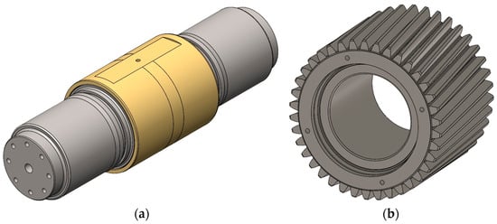
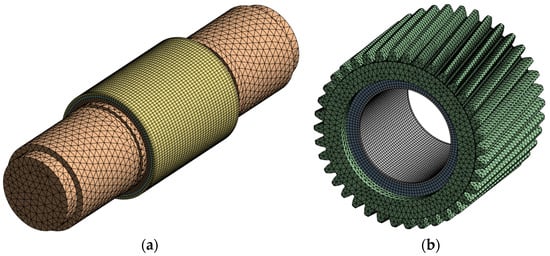
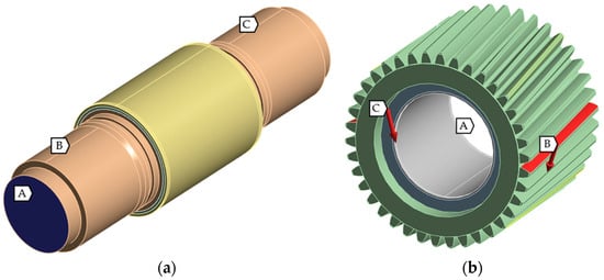
Elastic deformation is accounted for in the calculation by means of reduced stiffness matrices [19]. The model assumes linear-elastic behavior, requiring only the Young’s modulus and Poisson’s ratio as input parameters. These are defined in ANSYS (workbench version 2022 R1, Ansys, Inc., Canonsburg, PA, USA) as material properties. The journal bearing system is modeled using the pin geometry depicted in Figure 1a and the planet gear geometry illustrated in Figure 1b. The planet pin is designed with a shrink-fitted bushing.
Figure 1.
CAD model for pin (a) and planet (b).
2.3. Meshing for Structure Analysis
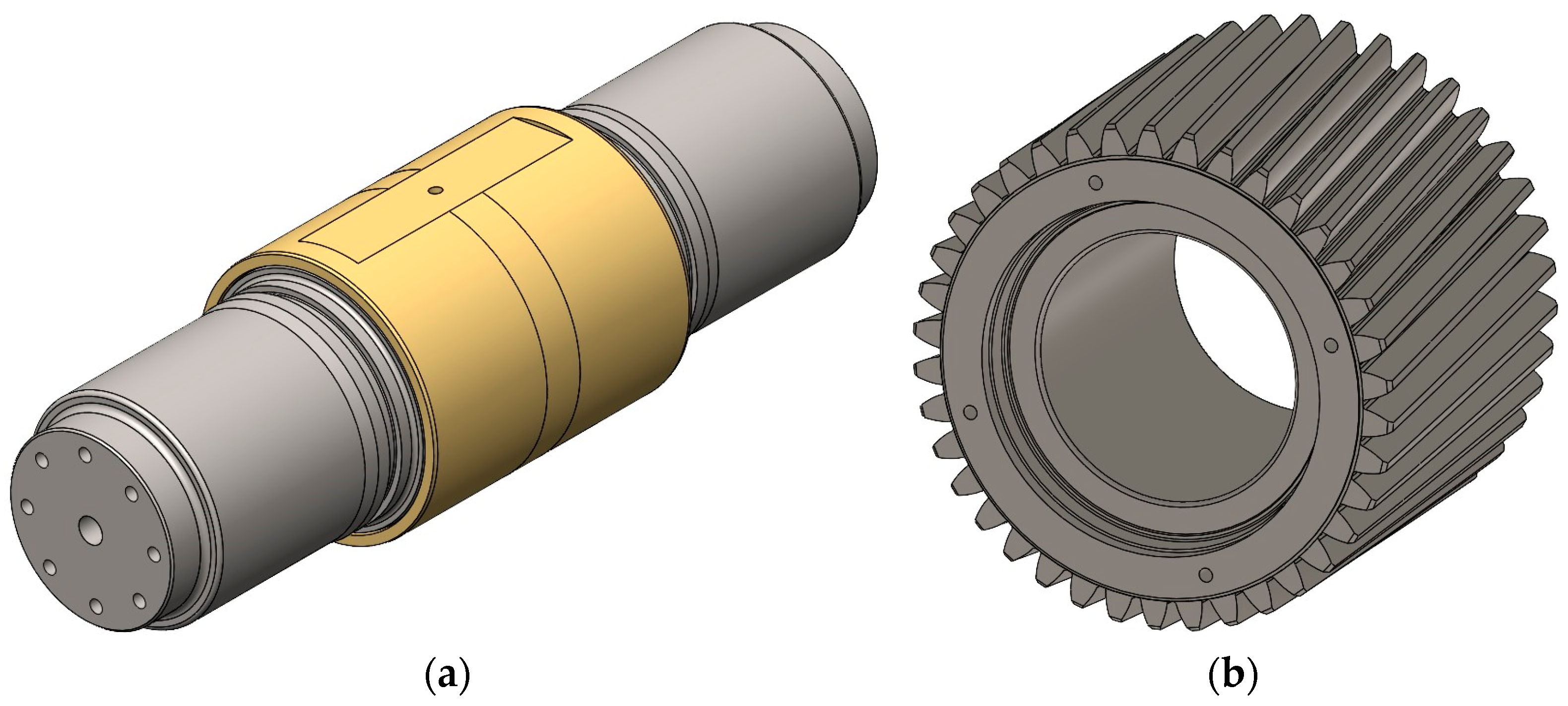
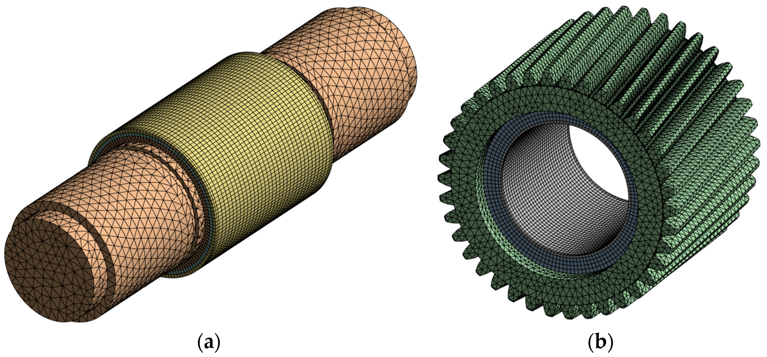
During mesh generation, selected edges, fillets, and holes are removed to avoid discontinuities in mesh continuity. The removal of the supply pocket ensures a continuous sliding surface. During mesh generation, each component is subdivided into three distinct parts. The pin is assembled using bonded contacts between its sections, whereas the planet gear components are integrated through a shared topology to ensure geometric continuity. A structured hexahedral mesh is prescribed for the sliding surface, which must maintain identical node positions in both modeling systems. For further component meshing, a tetrahedral mesh is assigned to the internal region of the pin in Figure 2a and to the tooth geometry of the planet gear in Figure 2b. The hexahedral and tetrahedral mesh regions are coupled through an intermediate transition layer employing a quadratic shape function to ensure continuity and accurate interpolation across the interface.
Figure 2.
Meshing for pin (a) and planet (b).
2.4. Boundary Conditions and Forces for Structure Analysis
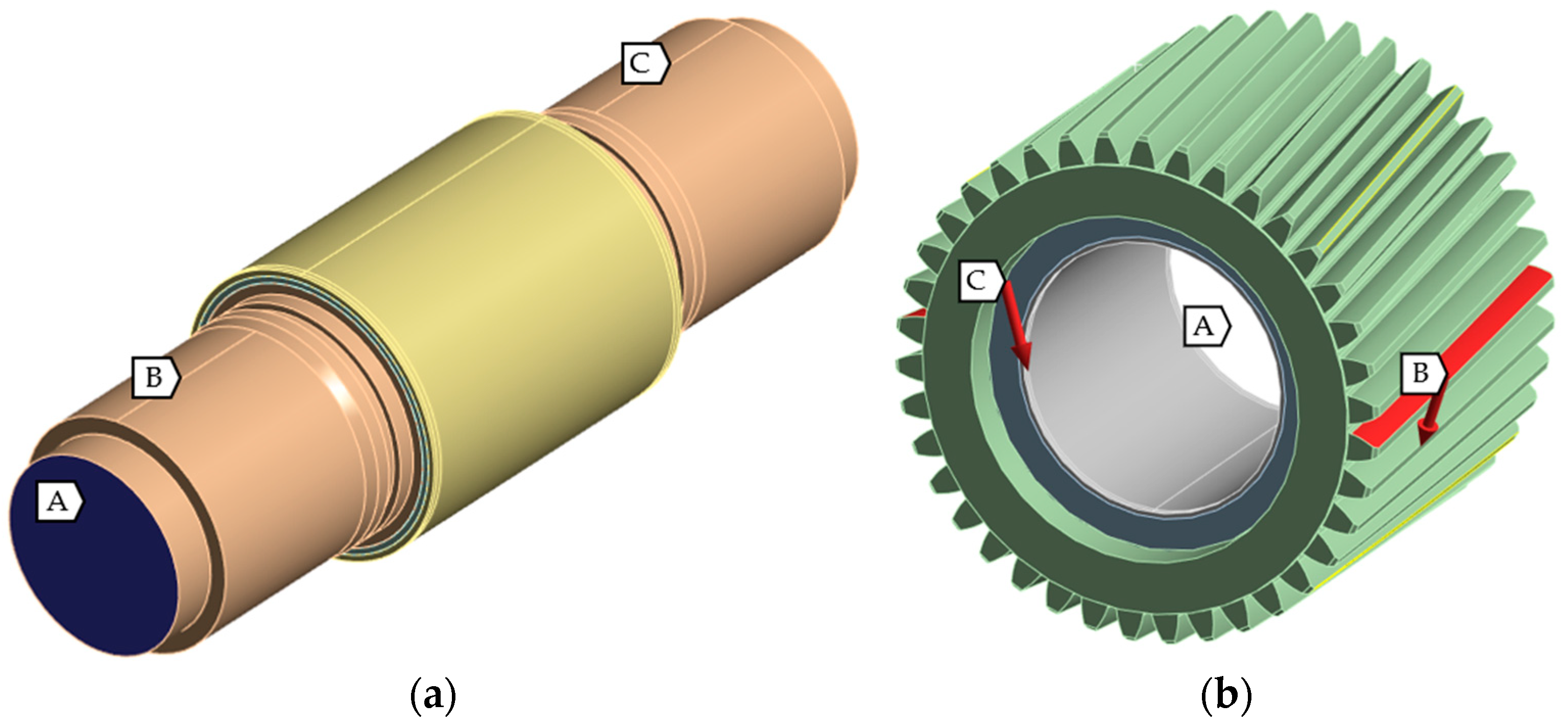
As boundary conditions for the pin in Figure 3a, a fixed support is defined on one outer surface (A), and external displacements are applied as line contacts on the two bearing surfaces (B, C). The fixed support represents the connection of the pin to the test rig via an adapter plate, while the external displacements model the two plain supports, maintaining free rotational movement. For the planet gear in Figure 3b, external displacements are applied to eight outer edges of the gear, since the planet cannot be assumed to be fixed due to journal bearing configuration. In this case, the external displacement functions as an elastic support, maintaining the spatial position of the planet gear (A). In addition, the forces listed in Table 1 are applied to the tooth flanks with the corresponding offset (B, C). As a result of these modifications, a new stiffness matrix is generated for each load case.
Figure 3.
Boundary conditions for pin (a) and planet (b).
Following the generation of the stiffness matrices using ANSYS APDL scripting, both the node coordinates and the stiffness matrices are imported into COMBROS PG for subsequent computational analysis [20]. The pocket geometry and the axial crowning profile are specified in COMBROS PG and incorporated accordingly in the calculations.
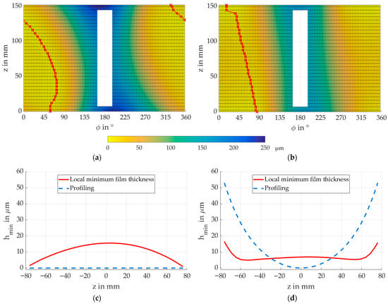
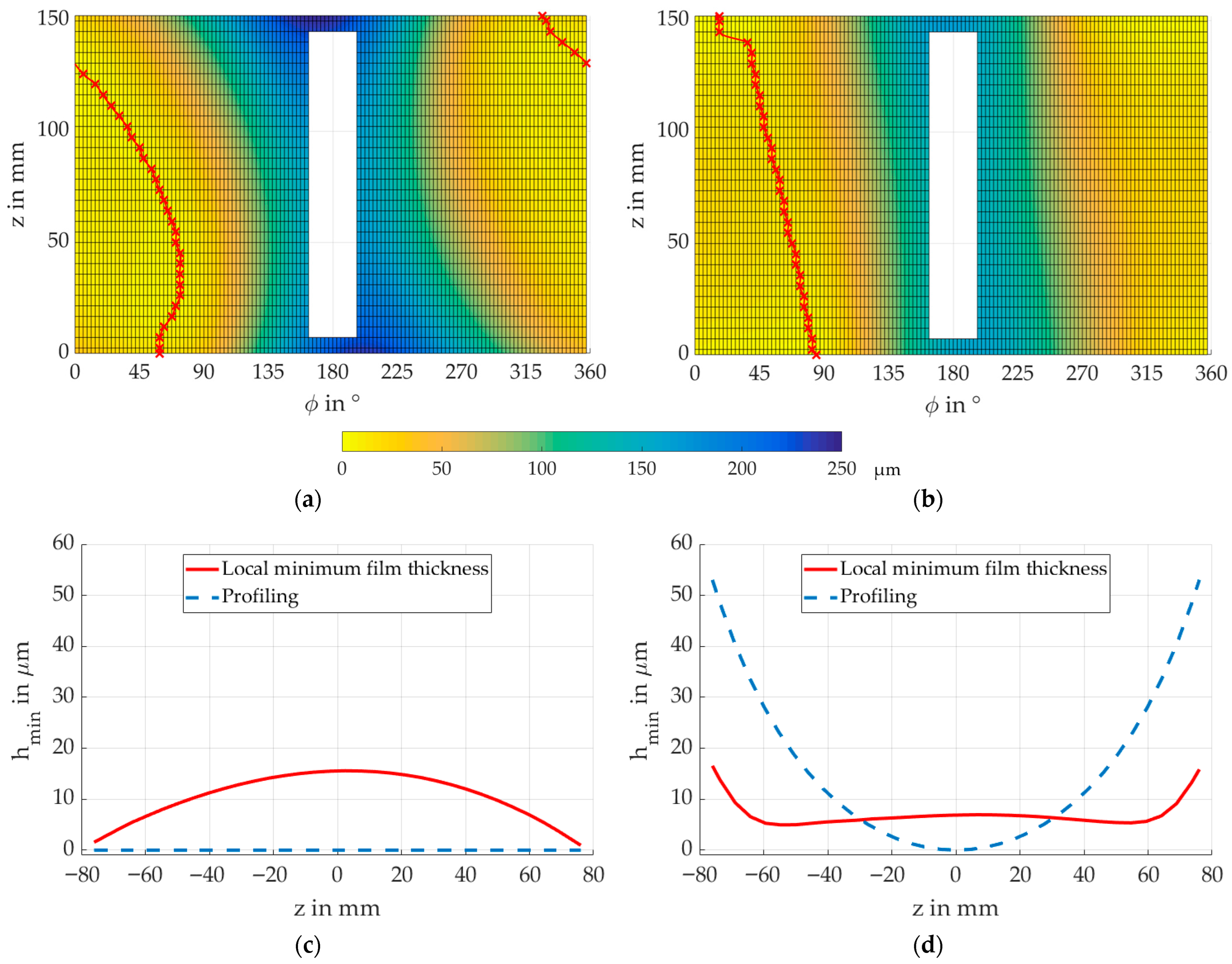
To determine the axial crowning profile, a calculation tool was developed based on the method proposed by Prölß et al. [12], which is integrated with the existing planet gear journal bearing calculation program. Within this framework, a possible initial profile and various optimization criteria—such as maximum of the minimum film thickness , uniformity of film thickness , or minimum lubricant film pressure —can be specified. Misalignment in planet gear journal bearings induced by forces and moments acting on the gear teeth leads to a helical distribution of the local minimum film thickness, as illustrated in Figure 4a. The corresponding reduction in film thickness toward the bearing edges across the bearing width without profiling is shown in Figure 4c. In the optimization procedure, an initial calculation is performed with or without an initial profile, from which the local minimum film thickness distribution is extracted. A polynomial of degree six is then fitted to this distribution and prescribed as the profile for the subsequent calculation step. The crowning profile is obtained from the film thickness according to Equations (1)–(3). First, the curve of minimum film thickness is determined, which represents the local minimum film thickness as a function of the axial bearing coordinate , see Figure 4a. Subtracting the maximum value of shifts the curve to ensure that the curve intersects the unprofiled pin surface. This constitutes the basis for determining the resulting profile. The addition of a relaxation factor multiplied with the curve of the local minimum film thickness from the previous iteration step helps to improve the convergence efficiency. This process results in the ideal profiling .
Figure 4.
Local minimum film thickness without crowning (a) and (c) and with crowning (b) and (d), based on Prölß et al. [12].
For manufacturing reasons, the profiling is approximated using a sixth-degree polynomial. Accordingly, a system of equations formulated Equation (2), from which the coefficients of the profiling are determined. Each row of the system consists of a sixth-order polynomial evaluated at the respective axial node position with the associated lubricant film thickness, as given in Equation (3). Only polynomial coefficients with even exponents are considered in order to obtain a symmetric profile.
This results in an overdetermined linear system of equations, which is rearranged and solved to obtain the coefficients of the profile. Finally, the fourth coefficient is set to zero in order to prevent a change in bearing clearance. This iterative process is repeated until the defined convergence criterion is achieved. For the design with respect to different optimization criteria, the profiling is adjusted according to the defined convergence criteria. Subsequently, the profile that fulfills the optimization criterion is selected and output from all calculation steps. The coefficients corresponding to the different optimization criteria are determined as described in Equations (4)–(6).
For the exemplary case of 30 iteration steps using the design criterion of maximum minimum film thickness, the resulting minimum film thickness distribution is presented in Figure 4b. The associated profile and the film thickness distribution across the bearing width are shown in Figure 4d.
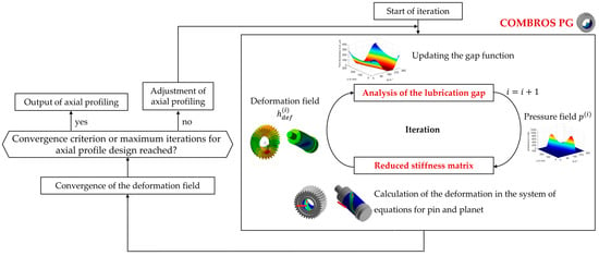
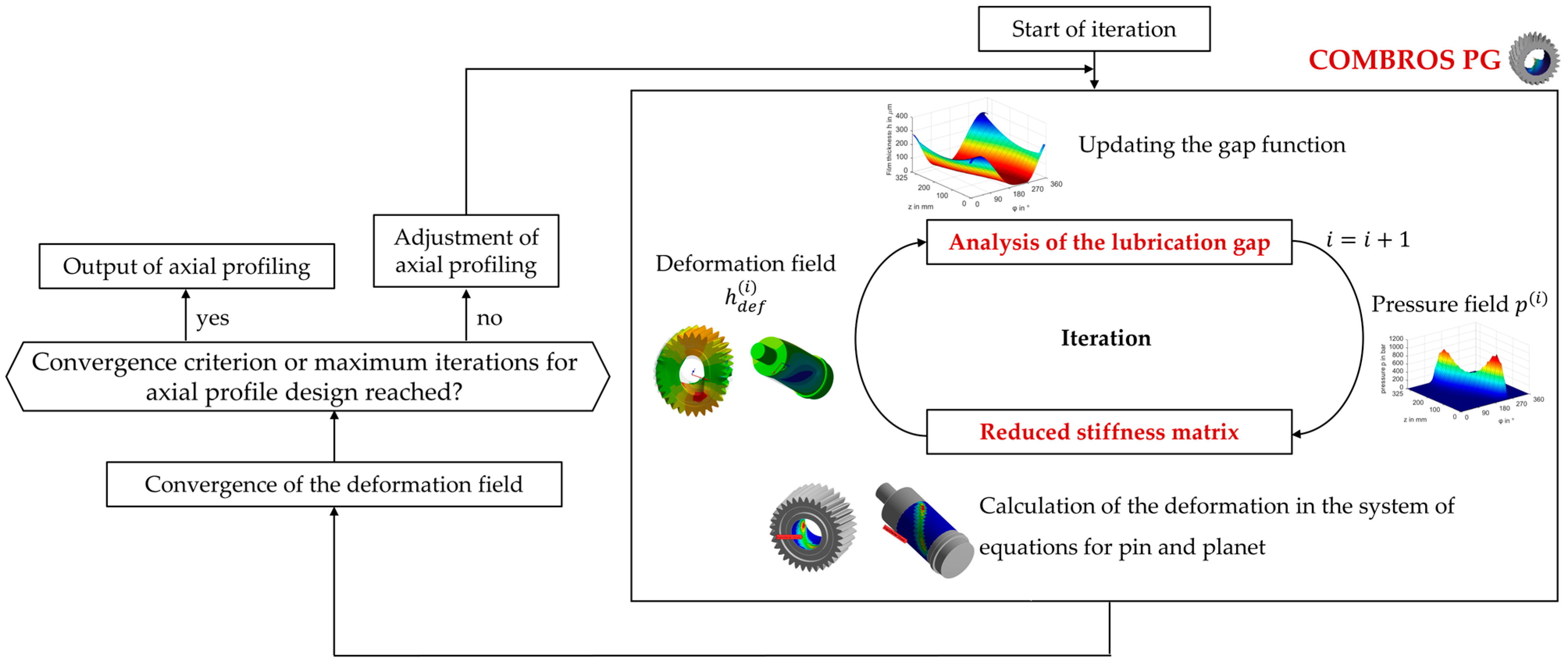
For efficient solution and convenient control, the automation is integrated into the existing calculation algorithm. Figure 5 presents the iterative workflow of the primary calculation program together with the auxiliary module for the design of the axial crowning profile. To improve computational efficiency, deformation field data from the preceding iteration can be utilized in the subsequent calculation with an updated profile. Upon convergence of each calculation cycle, an axial profile is generated.
Figure 5.
Computational procedure for axial crowning profile design.
This profile is used as input for the subsequent iteration step. The design of the axial crowning profile is investigated by performing multiple computational analyses for each of the two load cases. Initially, profiles are determined for both rigid and elastic geometries, after which the results and associated computation times are compared. Subsequently, a profile for an elastic geometry is designed under low- and high-load conditions, and the alternate load case is computed using this profile. This procedure highlights the influence of the operating condition considered in the design stage on the final results. Lastly, the impact of defining an initial profile and designing with respect to various optimization criteria is analyzed.
2.5. Experimental Procedure on the Planet Gear Journal Bearing Test Bench
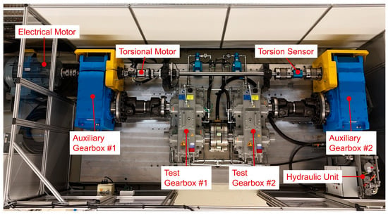
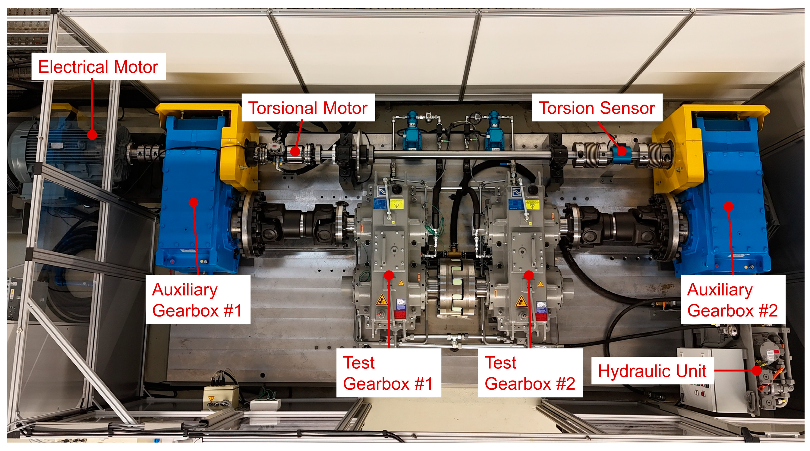
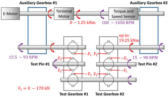
For the investigation of the influence of pocket position on the flow rate, the planet gear journal bearing test bench shown in Figure 6 is used. The test rig enables reproduction of typical load-circumferential speed combinations of a first planetary stage in a wind turbine by means of two test gearboxes, which are arranged in the test assembly and mechanically opposed to one another.
Figure 6.
Planet gear journal bearing test bench used for the measurements of lubricant flow rate.
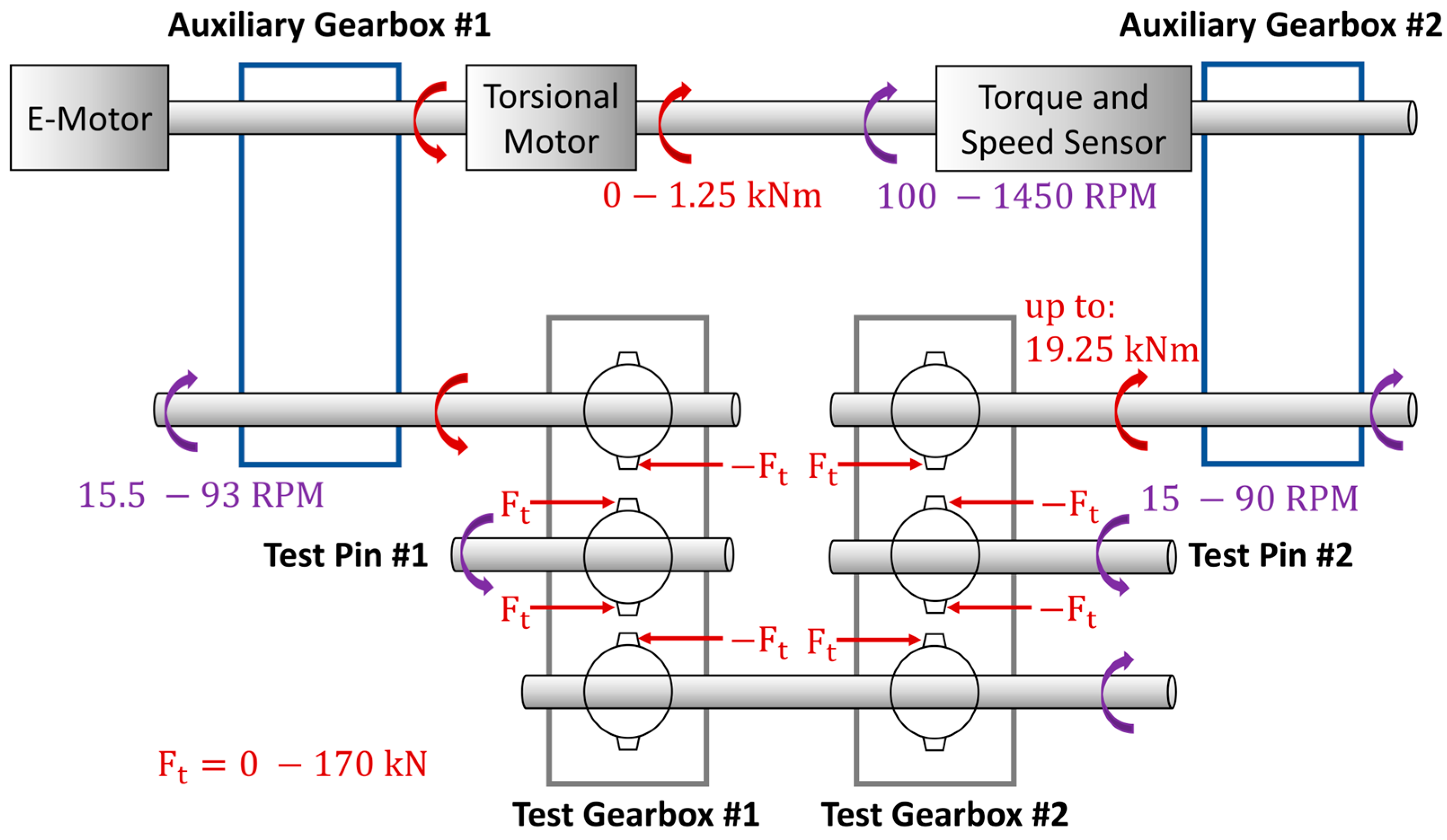
The test rig is equipped with a hydraulic torsion motor to apply the torque load and an electric motor to drive the planetary gears. Torque and rotational speed are regulated through two independent feedback control loops, enabling decoupled adjustment of these two parameters. This configuration facilitates the accurate simulation of transient operating conditions, including acceleration and braking phases. The rotation and force diagram in Figure 7 shows the directions of torque and forces acting on the planet gear journal bearing in the case study considered.
Figure 7.
Rotation direction and force schematic of the planet gear journal bearing test bench.
The general test bench parameters, lubricant data and technical specifications of test bench sensors are given in Table 2.
Table 2.
Overview of test bench parameters.
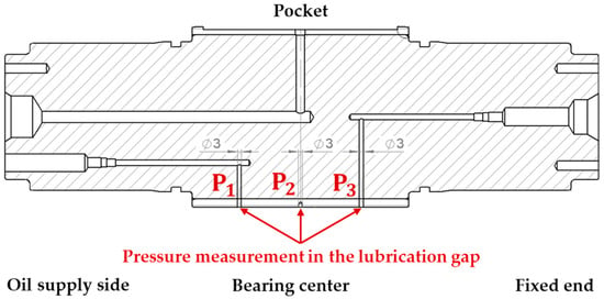
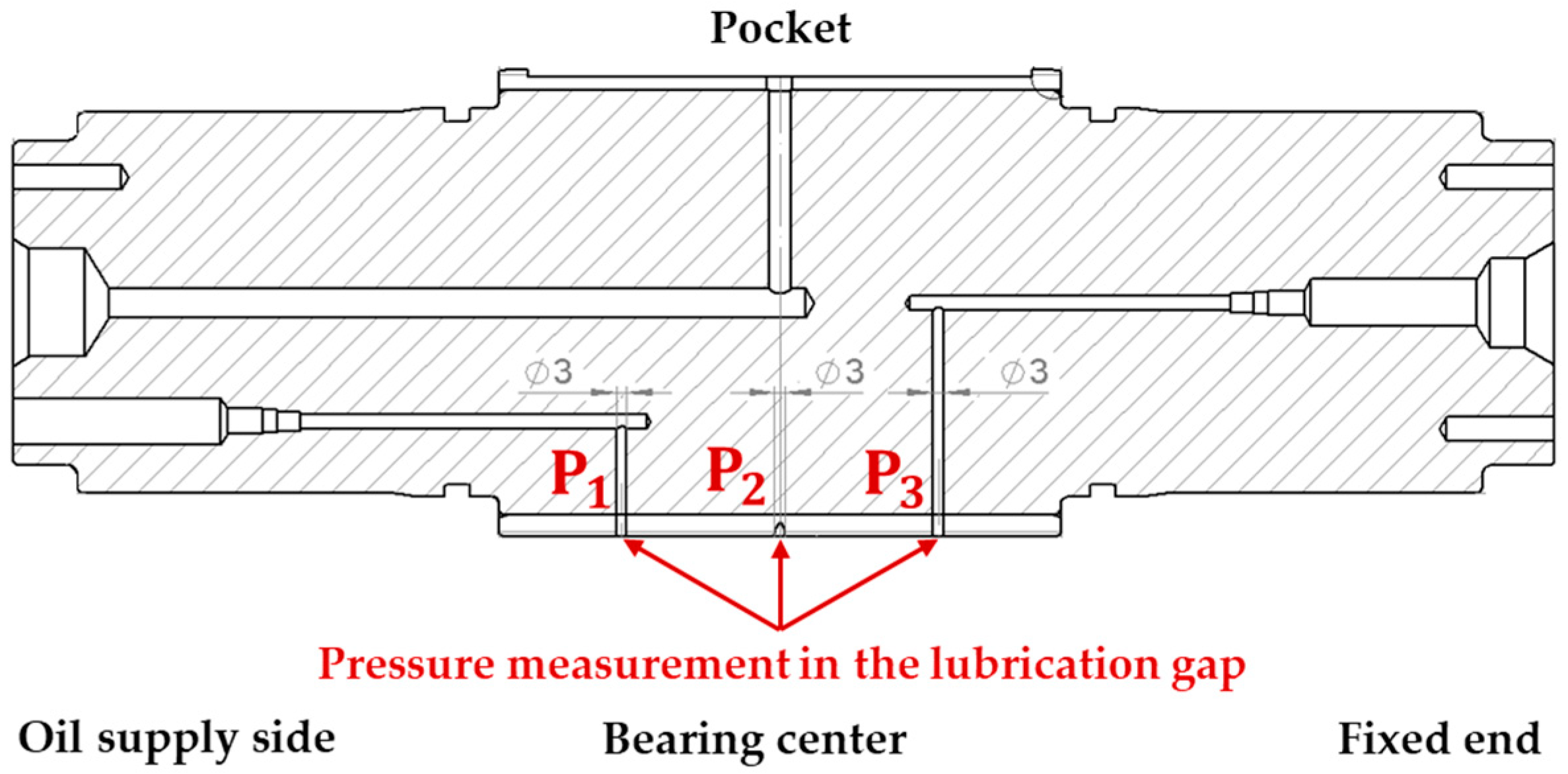
Three sensors are used for pressure measurement; their positions and designations are shown in Figure 8.
Figure 8.
Positions of pressure sensors P1, P2 and P3 in the planetary pin.
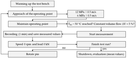
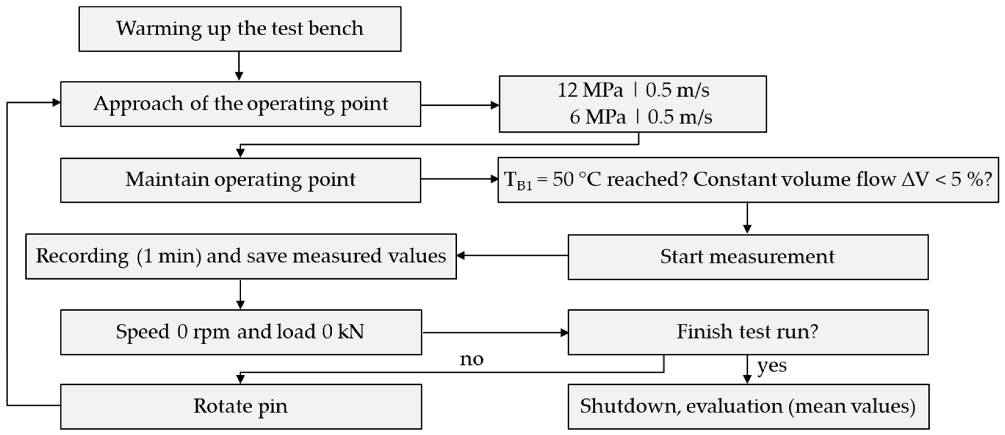
In order to guarantee consistent operating conditions for the flow rate measurements, a standardized test procedure, illustrated in Figure 9, was established. Following measurement at a defined load and rotational speed, the pin is rotated to vary the pocket position relative to the load direction.
Figure 9.
Experimental procedure for investigating the supply flow rate using pin rotation.
Table 3 presents the experimental plan for the tests conducted on the test bench. For the experiments, a planet pin with a prescribed profile was specially manufactured. The profile was applied to the planet bushing using a Computerized Numerical Control lathe(CNC) after the bushing had been shrink-fitted onto the pin. Profile correction was carried out directly on the CNC machine using a digital dial gauge with a tolerance of 1 μm. Finally, the profile was measured using a coordinate measuring machine (MAHR MMQ 400, Mahr GmbH, Göttingen, Germany). The bearing geometry along with the load cases and forces acting on the planet listed in Table 1 are used for the experiments. The bearing clearance was verified after manufacturing using the coordinate measuring machine and exhibits slight deviations due to manufacturing tolerances. The actual bearing clearance was considered accordingly in the numerical analyses.
Table 3.
Experimental parameters for the investigation of the influence of lube oil supply pocket.
To evaluate the influence of lube oil supply pocket, a flow rate is measured in the supply pipe and calculated for each pocket position, and the results are subsequently compared. This allows conclusions to be drawn regarding the optimal pocket position for the given geometry and operating conditions, which can be transferred to other applications involving slow-rotating and heavily loaded planet gear journal bearings.
3. Results
3.1. Design and Optimization of Axial Profiling
3.1.1. Comparison of Profile Designs Based on Rigid and Elastic Geometry
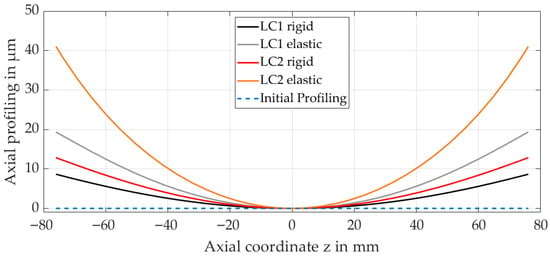
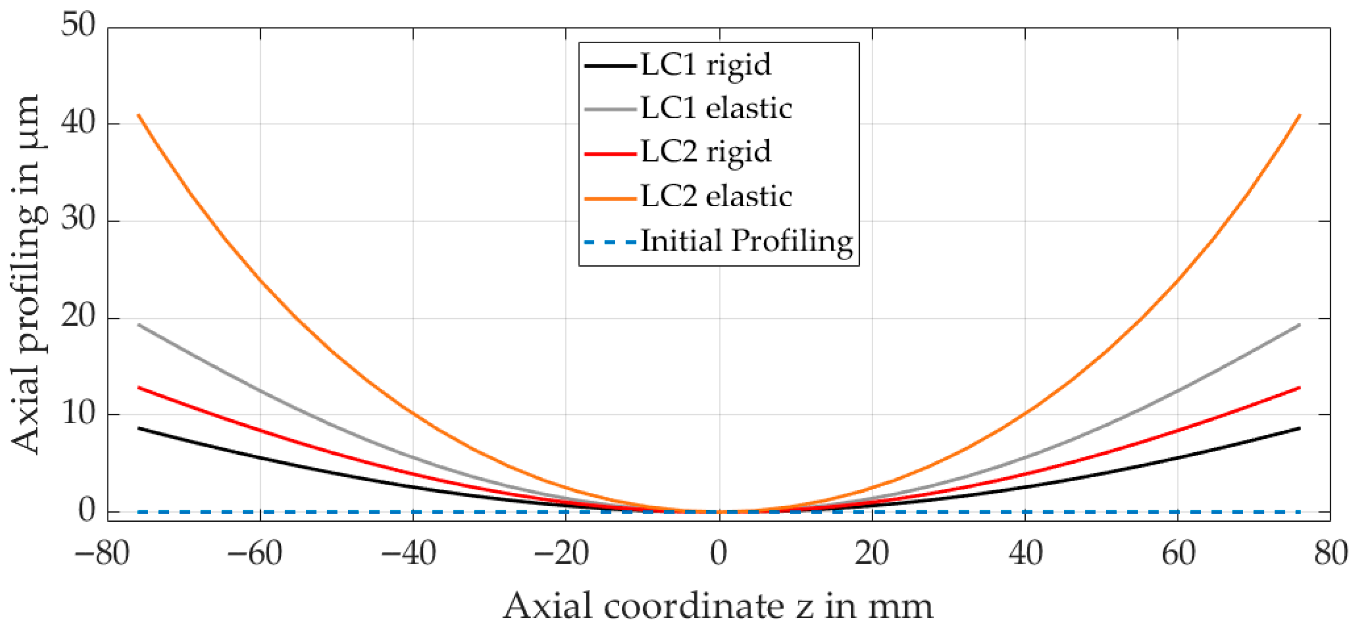
To investigate the influence of rigid versus elastic geometry, a crowning profile design is conducted for each of the two load cases, using the design criterion of uniformity of film thickness. The resulting profiles are presented in Figure 10. Subsequently, an elastic calculation was performed with a specified crowning profile. Significant differences are observed, particularly in the region of the bearing edges. In the case of a design for a lower load condition combined with a rigid geometry, a generally weaker crowning profile is obtained. This highlights the significant influence of component deformation in highly loaded, slow-running planet gears.
Figure 10.
Resulting profiling for 6 MPa (LC1) and 12 MPa (LC2) for rigid and elastic calculation.
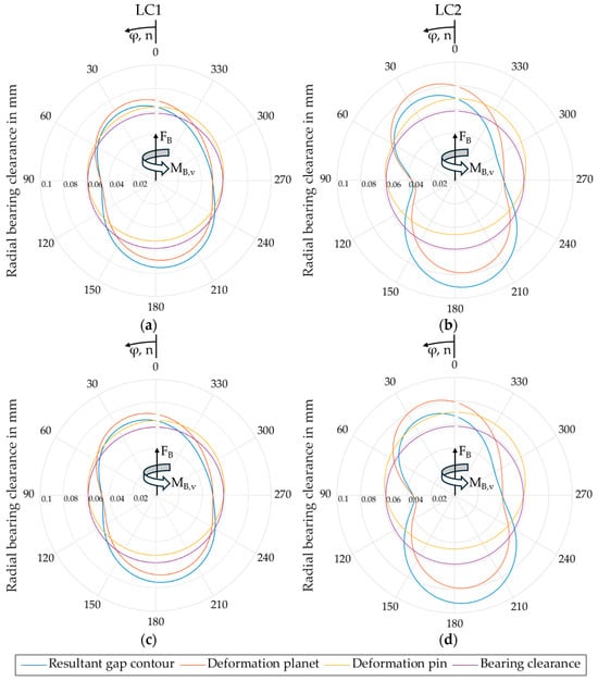
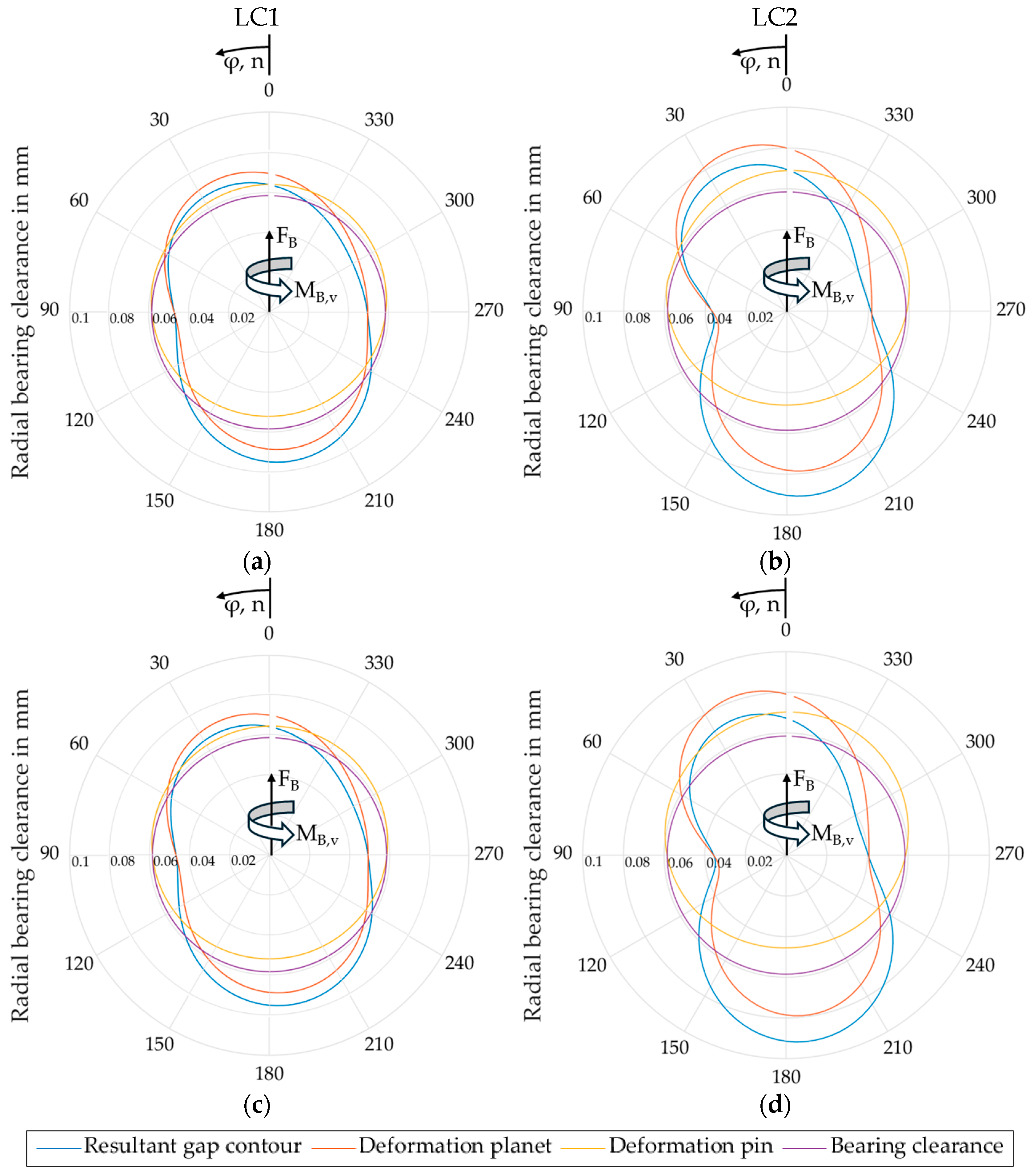
Figure 11 shows the deformations at the bearing edge at an axial coordinate of 2.375 mm calculated using the designed crowning profiles. The resulting gap contour reveals differences in deformation, particularly in the load zone in the range of 0° for LC1 and LC2. Nevertheless, the differences in deformation at the bearing center are minimal due to the symmetrical crowning and the similar profile geometry, as shown in Figure 10. The differences in deformation are significantly larger due to the crowning profile shape at the bearing edges. Especially for LC2, a pronounced variation in the resulting clearance contour is observed.
Figure 11.
Calculated deformation for pin and planet for LC1 rigid (a) and elastic (c) and LC2 rigid (b) and elastic (d) at the bearing edge.
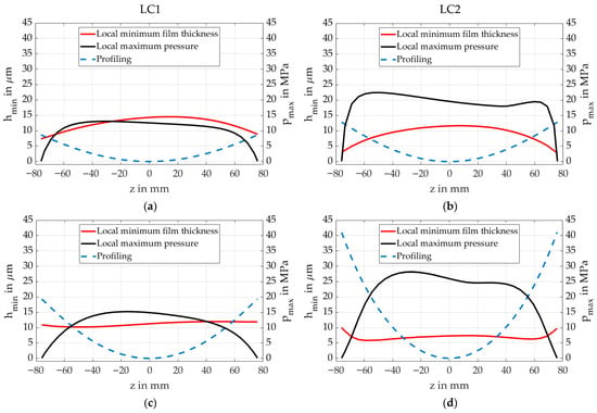
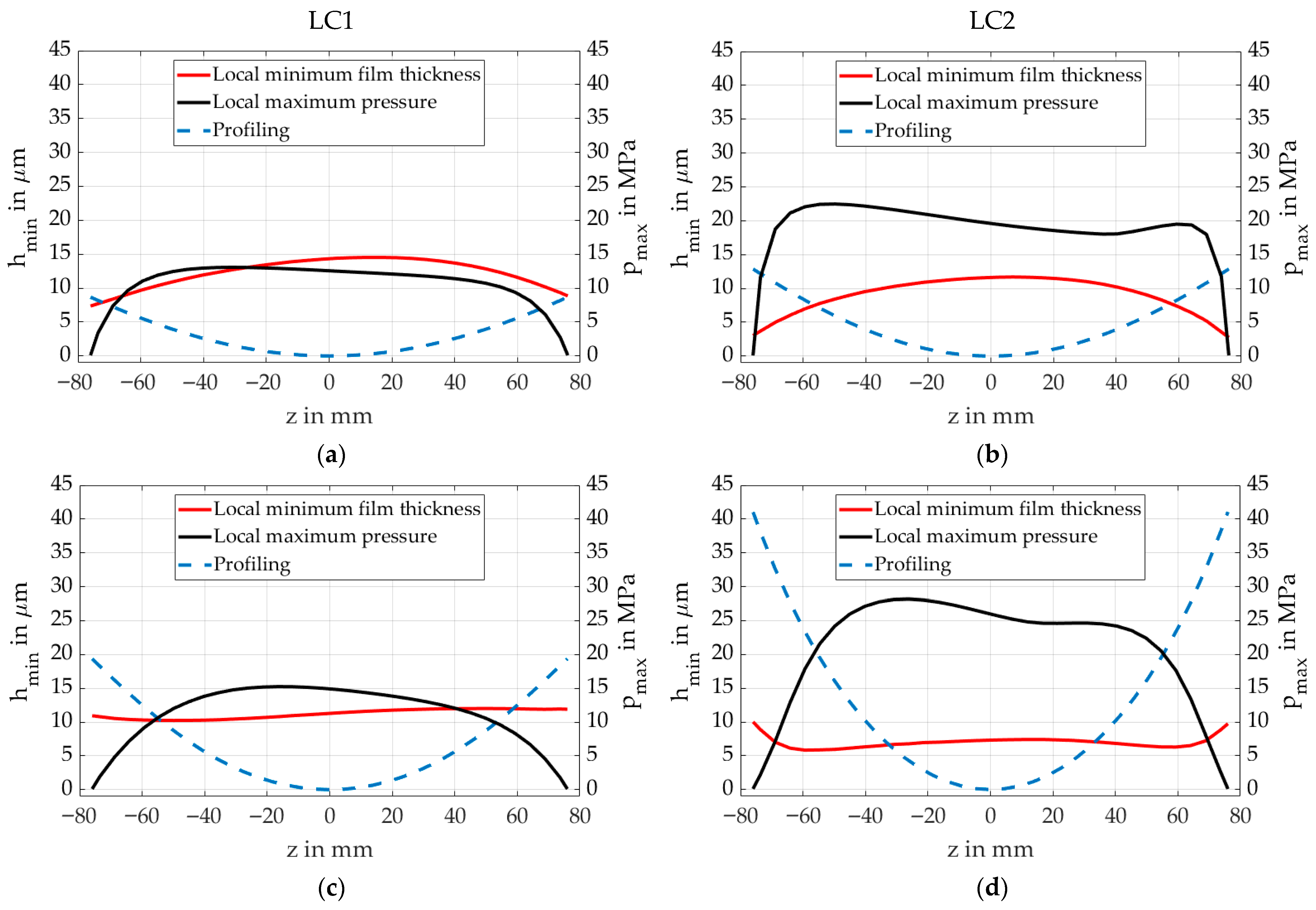
To fully assess the design methodology, the film thickness profiles and pressures are evaluated, as presented in Figure 12. The depicted film thickness represents a curve of the minimum film thickness values for each axial coordinate, see Figure 4. The pressure is determined analogously, as a curve of the maximum values for each axial coordinate. The calculation results are summarized in Table 4. For a rigid design with elastic calculation, the resulting crowning profile is generally weaker, particularly at the bearing edges. While this increases the local minimum film thickness compared to the case without profiling, the process of equalizing the gap height is limited, and small film thickness values still occur at the bearing edges. With an elastic design, a more uniform film thickness can be achieved. This results in higher lubricant film thickness at the bearing edges, which is advantageous for bearings subjected to high edge loads. In the calculation example, the maximum pressure does not occur close to the bearing edges. Consequently, for a rigid geometry design, smaller minimum gap heights are obtained at the edges, but the pressure is reduced due to the higher minimum film thickness in the bearing center. This accounts for the fact that the elastic design yields a larger minimum gap height, yet a higher pressure. The relationship between pressure and film thickness originates from the Reynolds differential equation, which can be formulated based on the simplified Navier–Stokes equations [21]. Based on this, Prölß [19] derives the dimensionless form incorporating the viscosity-dependent coefficient . Due to the low flow velocities, the turbulence correction factors can be neglected for the calculations performed in this study, resulting in Equation (7).
Figure 12.
Film thickness profiles for LC1 and LC2 with rigid (a,b) and elastic (c,d) design.
Table 4.
Comparison of calculation results for designs with rigid and elastic deformation.
The numerical solution of the Reynolds equation using the finite volume method is described in Prölß [19]. The equation shows that film thickness contributes to the pressure calculation with a cubic dependence. As a result, even minor variations in film thickness have a pronounced impact on the computed pressure. For a non-uniform film thickness profile, where the thickness increases towards the bearing center, the pressure drops markedly, which accounts for the effect observed earlier. Furthermore, an elastic geometry design results in a more gradual pressure decrease towards the bearing edges. The results suggest that an elastic geometry design is generally preferable. Additionally, the profile resulting from the elastic design is not simply a scaled version of that obtained from the rigid design. The consideration of elasticity therefore changes the characteristics of the profile. Although the comparison of computation times in Table 4 reveals a significant time saving for a rigid design, this is highly dependent on the number of iteration steps.
When an elastic design is carried out for both load cases and the respective opposite load case is subsequently calculated, the results are obtained as shown in Table 5. The minimum film thickness for the calculated load case with its corresponding profile is clearly higher than for the opposite load case. However, the profiling designed for LC1 shows very low calculated minimum film thickness values when applied to LC2. In contrast, the profiling designed for LC2 still provides adequate thickness when applied to LC1. This indicates the necessity of designing the profile for the highest load case, for which the calculation of additional operating points with lower loads yields reliable results.
Table 5.
Comparison of calculation results for designs with rigid and elastic deformation for different load cases.
3.1.2. Comparison of Designs with and Without Initial Profile
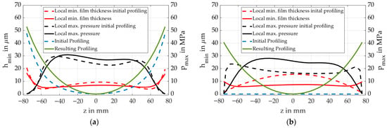
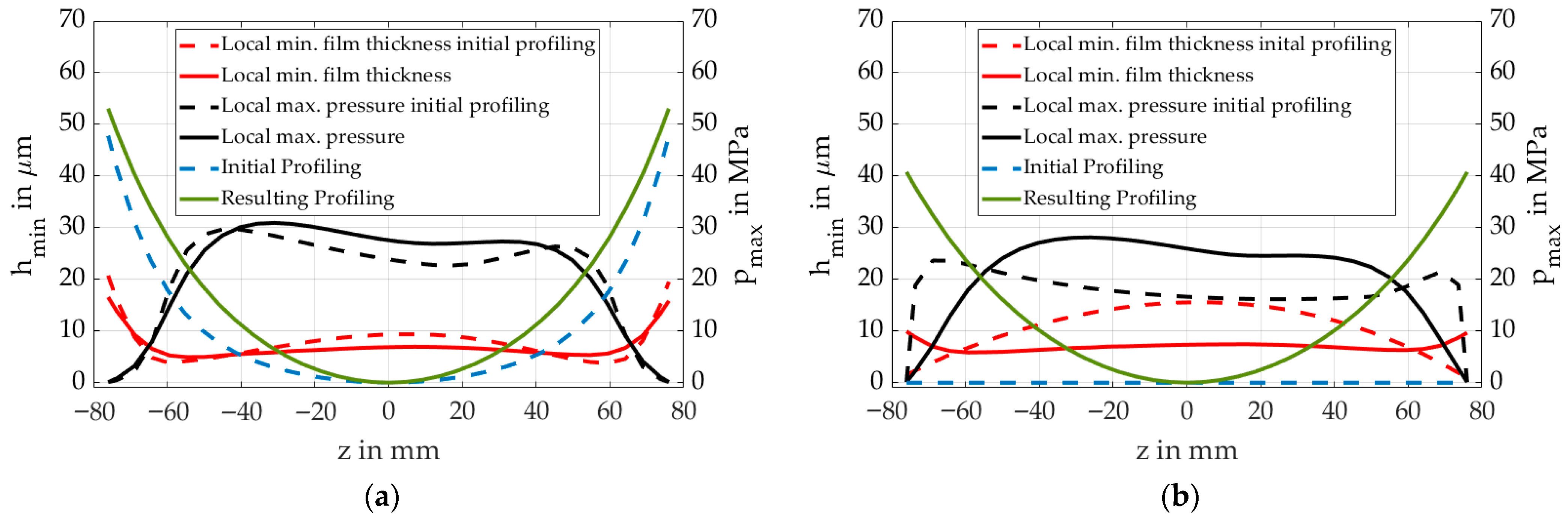
The determined axial crowning profiles for the input with and without initial profile specification, as shown in Figure 13, exhibit remarkable differences particularly at the bearing edges. This leads to variations in the calculated film thickness, pressure, and lubricant flow rate, as summarized in Table 6. When the optimization is performed with an initial profile specification, the program aligns with this predefined geometry and adapts the profile. In contrast, without an initial profile specification, an entirely new crowning profile is generated. The difference originates in the first iteration step: the film thickness displays a completely different distribution, from which the profile is derived. Subsequent optimization steps are based on this profile, which explains the variations in the resulting geometries. Thus, the optimization problem does not represent the minimization of a globally valid function. Instead, it is the adjustment of locally updated properties. If the initial profile is incorrectly selected for the operating conditions, the calculation results indicate increased pressure, reduced film thickness, and increased flow rate. Therefore, for new operating conditions, it is generally more effective to determine new crowning profiles rather than optimizing existing designs from other applications.
Figure 13.
Resulting profile for the design with (a) and without (b) initial crowning.
Table 6.
Calculation results for the comparison with and without initial crowning profile.
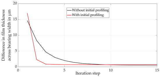
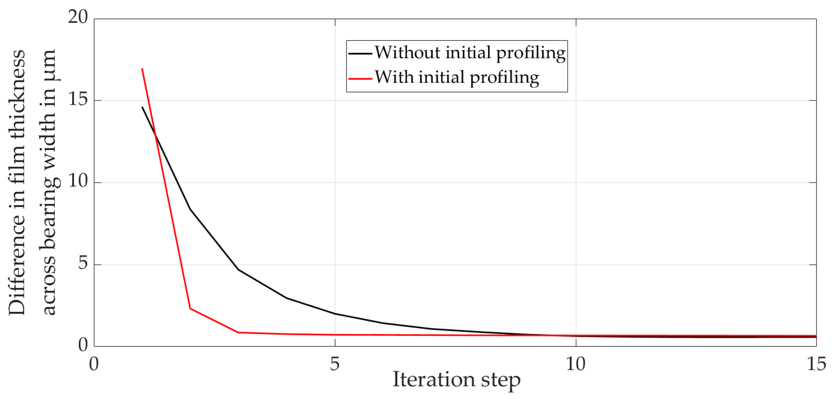
Monitoring of the optimization process in Figure 14 shows that the design, with respect to the design criterion of uniformity of film thickness, converges significantly faster when an initial profile is specified. However, due to the unfavorable initial profile, the difference in minimum gap height is initially higher. The observed effect is due to the reduced extent of adjustments required for an existing profile, in contrast to the gradual formation of a completely new profile when no initial specification is provided.
Figure 14.
Iteration process of difference in film thickness with and without initial profiling.
3.1.3. Comparison of the Design Based on Various Design Criteria
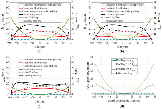
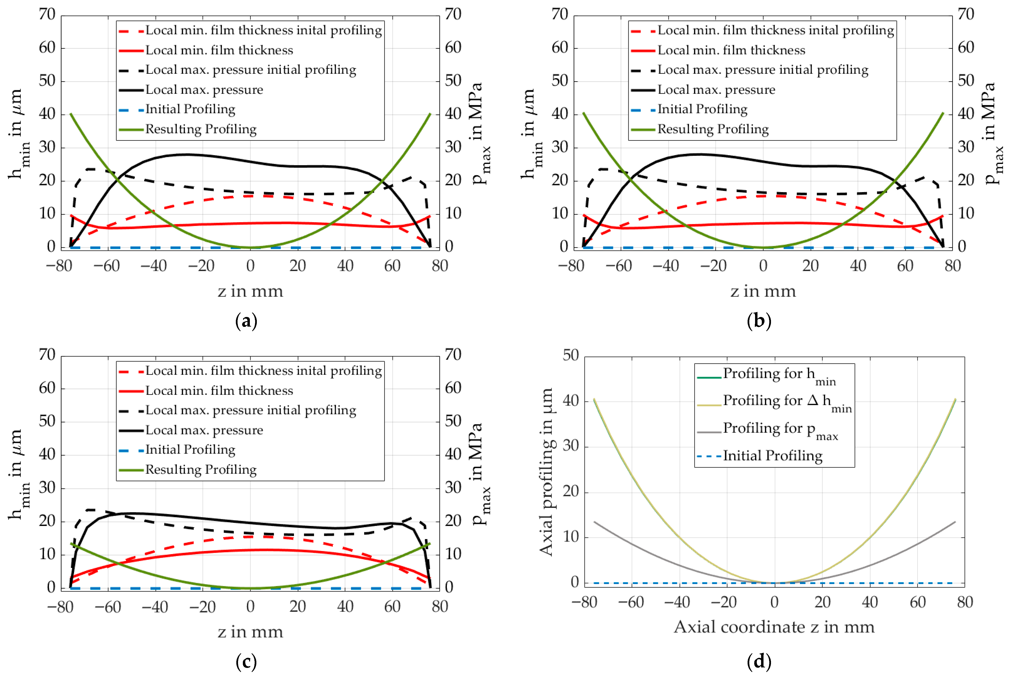
To investigate the design with respect to the optimization criteria of maximum minimum film thickness, film thickness uniformity, or minimum lubricant film pressure, no initial profile is specified. Figure 15 presents a comparison of the calculated crowning profile, the film thickness, and the lubricant film pressure for each design criterion, as well as a comparison of the resulting profiles. The designs optimized for maximum minimum film thickness and for film thickness uniformity yield almost identical results, with negligible differences in the resulting profiles and computational outcomes, as shown in Table 7. In contrast, optimization with respect to the minimum lubricant film pressure produces a significantly lower curvature profile, which—similar to Figure 12b—exhibits smaller film thicknesses at the bearing edges. The increase in film thickness towards the bearing center reduces the lubricant film pressure. This type of profiling should be avoided under high bearing moment loads and edge load conditions. In particular, during special events such as start-up or emergency stops, significant pressure peaks may occur, making it essential to ensure sufficiently high film thickness across the entire lubrication gap. This further suggests that focusing on film thickness uniformity constitutes a more reliable design methodology, since even optimization for maximum minimum film thickness can lead to issues in different bearing geometries and operating conditions when the film thickness distribution is irregular.
Figure 15.
Resulting profile for optimization criteria maximum minimum film thickness (a), uniformity of film thickness (b), minimum lubricating film pressure (c) and comparison of profiles (d).
Table 7.
Calculation results for the comparison with different optimization criteria.
3.2. Investigation of the Influence of Lubricant Supply Position on Flow Rate
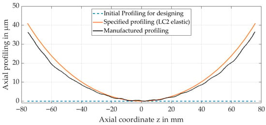
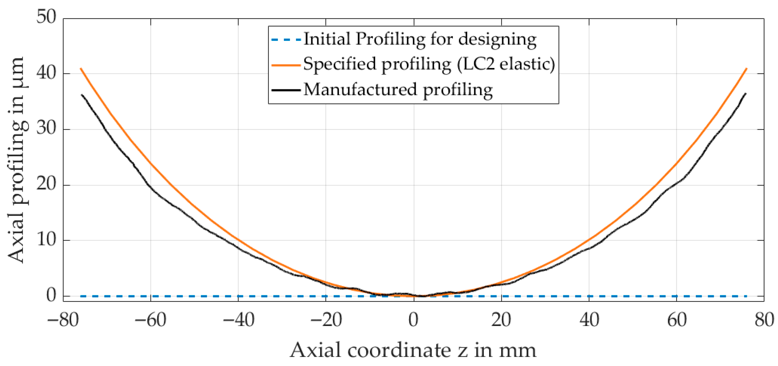
The profiling was designed for the experiments for a load case of 12 MPa while accounting for elastic deformation. The profile was verified after manufacturing. Due to manufacturing tolerances, the manufactured profile deviates toward the edges by approximately 4 µm. In the calculations, the actual profiling is prescribed as an input parameter. A comparison between the prescribed and the manufactured profiles is shown in Figure 16.
Figure 16.
Comparison of specified and manufactured profiling.
The operating point calculations were performed using the model and corresponding stiffness matrices from Section 2.1, combined with the optimized crowning profile. The load cases applied correspond to those listed in Table 1. In the calculation program, the flow rate is determined in accordance with Equation (8) which results from the integration of axial volume flow via the whole bearing edge and output upon completion of the overall computation. This result is subsequently employed for comparison between the experimental measurements and the numerical predictions.
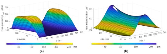
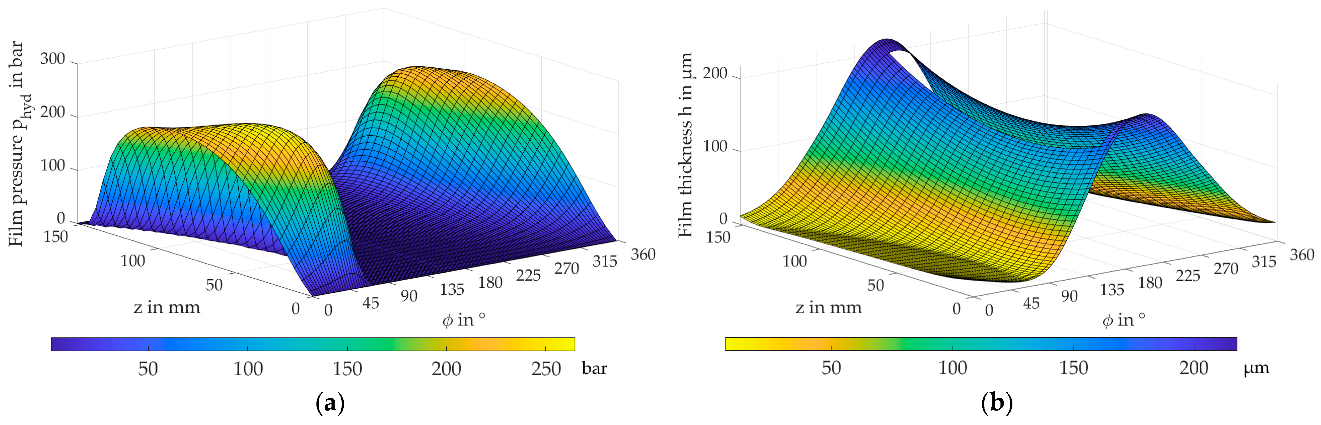
Figure 17 shows an example of the lubricant film pressure and film thickness distributions calculated with a pocket position of 180° for LC2.
Figure 17.
Calculation of hydrodynamic film pressure (a) and film thickness (b) with a pocket position of 180° for LC2.
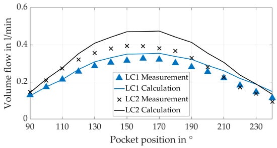
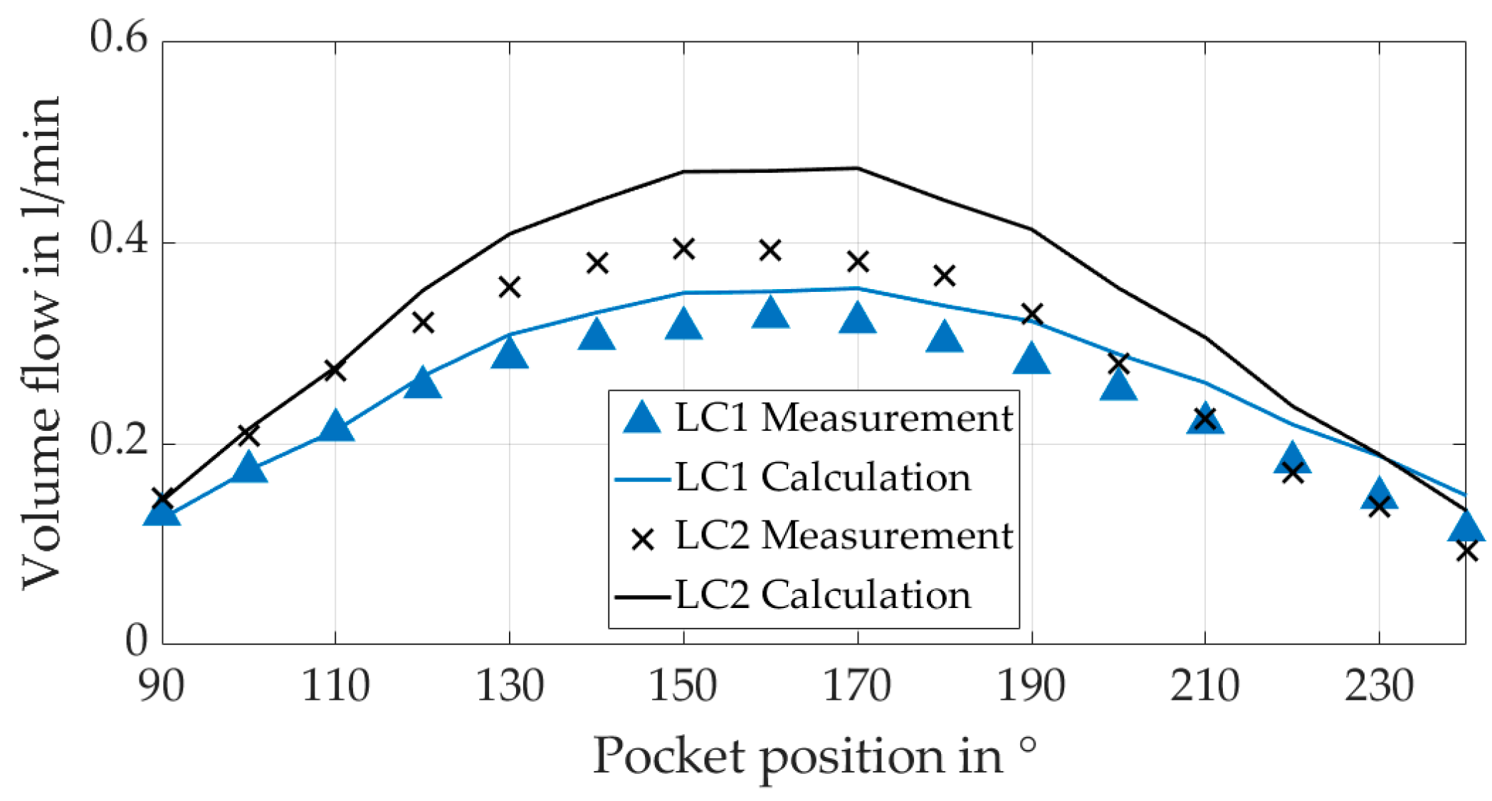
The measurement results in Figure 18 reveal an increase in flow rate with rising load. In addition, the flow rate increases markedly when the pocket is positioned opposite the pressure peak, in the circumferential angle range of 140° to 180°. Particularly at high loads, the variation in the flow rate exhibits steeper rises and drops with changes in pocket position. A comparison of the flow rate shows good agreement between the simulation, incorporating elastic deformation, and the experimental results. This deviation can be partly explained by the high sensitivity of the flow rate to thermal boundary conditions, which are difficult to define accurately for the simulations. The trends correspond closely; for LC2, a slight overestimation of the flow rate is observed. Despite this, the modeling approach can be considered sufficiently accurate for representing the overall system behavior.
Figure 18.
Calculated and measured flow rate as a function of pocket position.
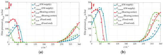
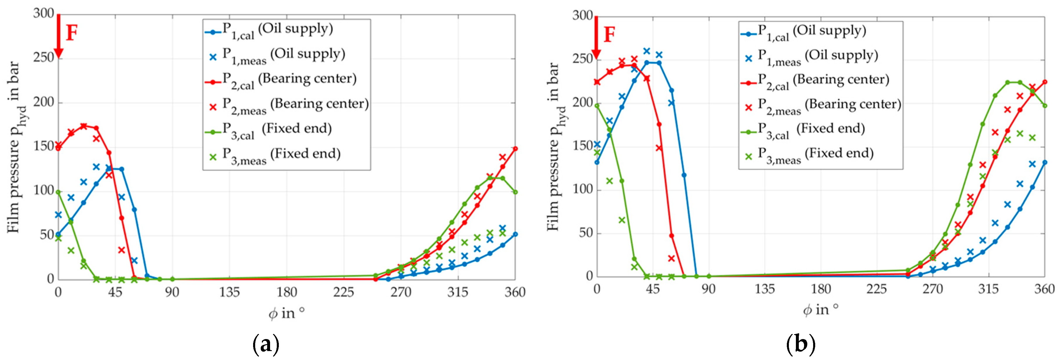
The pressure measurements are performed at a single circumferential position opposite the pocket at the sensor locations listed in Table 2. By interpolating the numerical results, the pressures P1 at the oil supply side, P2 at the bearing center, and P3 at the fixed end of the pin are determined at the respective pressure sensor positions. For a given pocket position, only one pressure value is evaluated. The measurements and calculations for pocket positions between 90° and 240° result in the pressure distributions over the circumferential angle shown in Figure 19. The comparison shows good agreement at the bearing center and at the oil supply side. However, the calculated pressure at the fixed end of the pin is significantly higher than the measured value, which may also contribute to deviations in the volume flow.
Figure 19.
Calculated and measured pressure for LC1 (a) and LC2 (b).
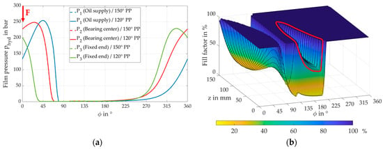
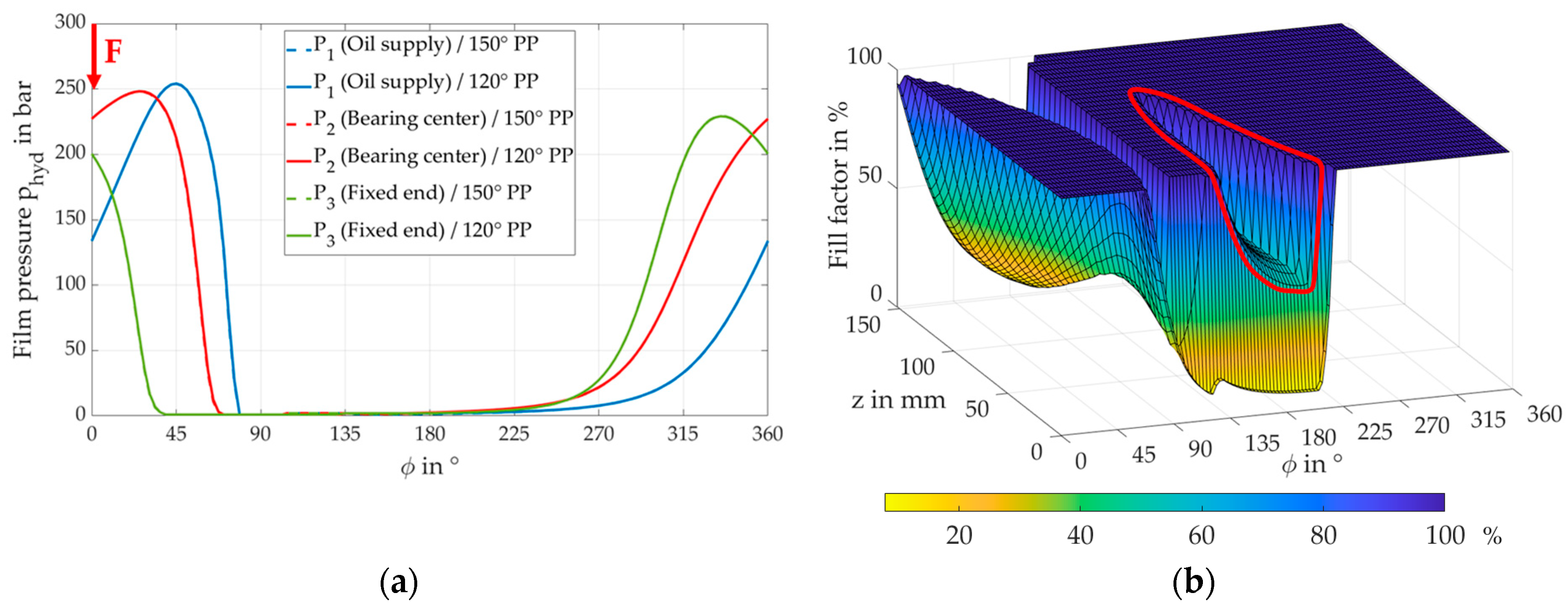
A comparison of the calculated pressure profiles in Figure 20a shows that the lubricant film pressure, and consequently the film thickness, remain nearly constant within a specific range for two pocket positions located behind the load zone. The difference in flow rates shown in Figure 18 is within an acceptable range for these two pocket positions and operating points, but it is highly dependent on the application and operating conditions. Under deviating operating conditions, such as increasing load, this can have a significant impact on the required supply flow rate and, consequently, on pump power demand. Furthermore, with an increasing number of planets, the total difference in flow rate rises significantly, which can be counteracted by correctly selecting or adjusting the pocket position if no other boundary conditions oppose this design degree of freedom. Figure 20b shows the calculated fill factor for a pocket position of 110°. The gap filling ratio, defined as a dimensionless parameter, is used to describe the fraction of the lubricant gap filled between the pin and the planet gear. A gap filling ratio below 100% indicates rupture of the lubricant film and, consequently, the potential occurrence of cavitation. The prevention of this condition is therefore of particular importance. When the pocket is located directly behind the pressure peak, the filling ratio is affected because the film thickness in this area rises rapidly and the oil is supplied within a zone of a smaller gap. As a result, the gap in this area is not completely filled, and the filling ratio decreases. In contrast, when the pocket is positioned farther from the pressure drop, the fill factor remains unaffected. From a hydrodynamic perspective, this does not present a problem for the specific applications. This situation can be effectively prevented by a small shift in the pocket location. Figure 20 only presents the comparison for LC2; analogous results can be observed for LC1.
Figure 20.
Calculated hydrodynamic film pressure (a) for a pocket position of 120° and 150° and calculated fill factor (b) for a pocket position of 110° for LC2.
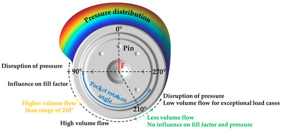
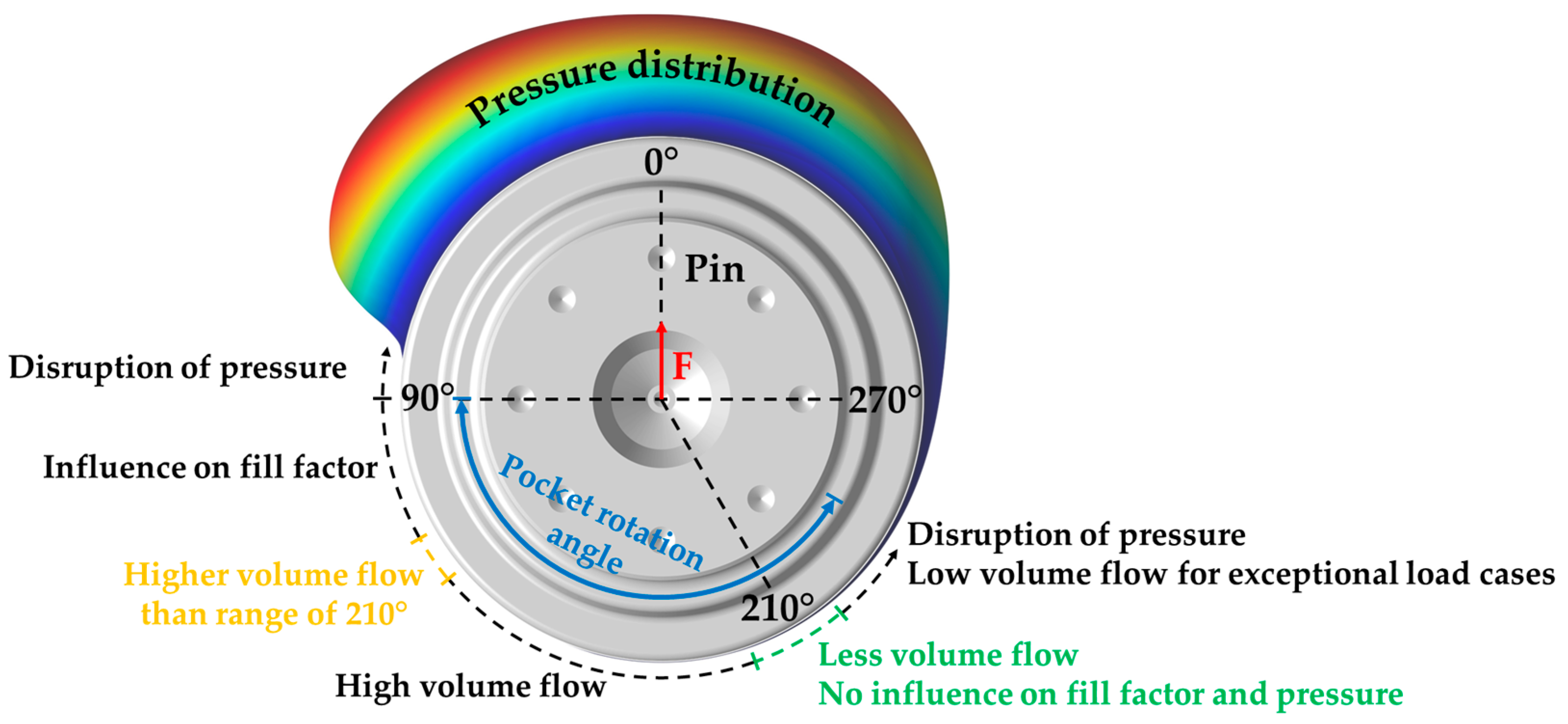
The pocket position should accordingly not be selected directly within regions of pressure decrease or pressure increase, as this disrupts the pressure build-up and leads to increased maximum pressures. When the pocket is positioned at a sufficient distance from the pressure drop or ahead of the build-up of the pressure peak, neither the pressure profile nor the formation of the hydrodynamic lubricant film is disturbed. In addition, the flow rate is significantly lower, and the bearing temperatures are not adversely affected, which results from the low rotational speed at these operating conditions. When selecting the pocket position angle behind the pressure peak or before positions with high flow rate, only a small range is available for pocket placement (120–130°). Positioning the pocket around 210° results in lower oil flow, making a location behind the region opposite the load zone appear more efficient. Figure 21 summarizes the results of the study on the lubricant supply position.
Figure 21.
Summary of the study on lubricant supply position.
From the investigations on the influence of lubricant supply position conducted on the planet gear journal bearing test rig for wind turbine applications, it can be concluded that a pocket position angle around 210° is recommended for the defined operating points and bearing specifications in this application. In this range, there is no risk of insufficient lubrication for any operating point and no adverse effect on the hydrodynamic film pressure. By selecting this pocket position, the flow rate can be significantly reduced compared with a configuration at 180° opposite the load zone, which also results in a reduction in pump power demand. Another positive aspect is the supply of fresh oil to the bearing before the build-up of the pressure peak, whereby the lubricant is supplied directly to the region of minimum film thickness rather than passing through the remaining gap. From a purely hydrodynamic perspective, and for stationary operating points, such a pocket position is therefore recommended. However, in other load cases—such as braking operations, changes in load direction, or idle running—where the pressure peak shifts along the circumferential angle relative to the load, certain pocket positions may have a much greater influence on bearing operating behavior and must be evaluated more critically.
4. Discussion and Conclusions
The necessity of axial crowning under moment loading conditions is well-supported in the literature. Previous investigations on axial crowning profiles have been examined to analyze the influence of misalignment and the resulting moment [4,5,6]. Direct studies on the profiling of journal bearings [7,8,9,10,11,12] complement this research by introducing various approaches for profile design. Due to detailed investigations using a method based on the approach proposed by Prölß [12], the conclusions of previous studies regarding improved bearing operating conditions achieved by axial profiling could be confirmed. Moreover, a significant influence of the mechanical boundary conditions and initial profiling on axial profile design was observed in this study. A review of the literature reveals that very few direct investigations have addressed the influence of lubricant supply pocket position in planet gear journal bearings. In contrast, several studies have examined this factor in journal bearings featuring a rotating shaft and stationary housing [13,14,15,16,17,18], with their conclusions largely supported by experimental data. This study shows that repositioning the supply pocket can significantly lower the volume flow inside the bearing. An optimal lubricant supply position for specific operating conditions was determined.
This paper investigates a method for designing the axial crowning profile in planet gear journal bearings, as well as its practical application in an extended calculation program. The bearing geometry and loading conditions used in this study are representative for slow-running and mechanically high-loaded journal bearings in wind turbine applications. Analysis of the design methodology considering rigid or elastic bodies reveals that crowning profile design should consider the elastic deformation due to a more pronounced profiling, as its magnitude is up to three times higher than the one designed on the basis of rigid geometries for the investigated case. For a specific bearing load of 6 MPa, accounting for elasticity results in a change of about 11 µm in the profiling at the bearing edges, while for 12 MPa the change increases to approximately 28 µm. Consequently, a reduction in the difference in the minimum film thickness from 7.2 µm to 1.8 µm for 6 MPa and from 9.0 µm to 4.2 µm for 12 MPa is observed, leading to a more uniform film thickness and a smaller pressure gradient towards the bearing edges. Furthermore, the specification of an initial profile is not advisable, as the resulting profile strongly depends on this initial specification. Overall, the study indicates that profile design should primarily aim at achieving a uniform lubricant film thickness.
The study was complemented by experimental investigations to identify the optimal location of lubricant supply pocket for wind turbine applications. By comparing the measured values with the computed flow rate and pressure, the reliability of the calculation model was confirmed. The analysis further indicates that repositioning the supply pocket can result in a considerable flow rate reduction. Shifting the pocket angle from 170° to 210° reduces the volumetric flow rate from 0.47 L/min to 0.30 L/min for the investigated operating conditions, corresponding to a reduction of up to one third. This effect becomes increasingly relevant as the number of planet gears increases and can lead to a substantial reduction in the required pump power. An optimal position of the feed pocket has been found for applications with operating conditions similar to those investigated, located ahead of the hydrodynamic pressure peak and the load zone. The results of this study are generally applicable to slow-running, highly loaded tribological systems. With respect to the utilization of planetary journal bearings in high-speed systems, further investigations are required due to different influencing factors. These factors include thermal effects on deformation as well as centrifugal effects on the lubricant film flow, which can markedly affect the operating behavior.
The continuous development of wind turbines is expected to result in higher specific bearing loads and decreasing gear rim thicknesses in the future, which increases the significance of deformation and its proper compensation. As wind turbine capacities continue to rise, higher power densities at the planet gear are anticipated, making the design of axial profiling along with an appropriate selection of lubrication supply pocket location increasingly important. Fundamental investigations in this research area enable a reliable design of the tribological system, supporting the fulfillment of steadily increasing requirements for efficiency and sustainable resource utilization.
Author Contributions
Conceptualization, S.H., J.Z., G.G. and T.H.; methodology, S.H., J.Z. and G.G., software, S.H. and J.Z.; validation, S.H. and G.G.; formal analysis, S.H. and J.Z.; investigation, S.H., J.Z. and G.G.; writing—original draft preparation, S.H., J.Z. and G.G.; writing—review and editing, S.H., J.Z., G.G. and T.H.; visualization, S.H., J.Z. and G.G.; supervision, T.H. and H.S.; project administration, T.H. and H.S.; funding acquisition, H.S. All authors have read and agreed to the published version of the manuscript.
Funding
Part of this research was supported by the Research Association for Drive Technology (FVA, Frankfurt, Germany) as part of the planetary plain bearings II research project (FVA 794 II) for optimization of lubricant supply, robustness and efficiency of planetary gears with plain bearings.
Data Availability Statement
For data protection reasons, the calculation program used cannot be made available for free use. The experimental data were collected as part of the aforementioned research project (FVA 794 II). Further investigations and data are presented in the corresponding reports; therefore, raw measurement data cannot be made available.
Acknowledgments
During the preparation of this manuscript/study, the author(s) used OpenAI GPT-5 Chat in Academic Cloud for the purposes of translation. The authors have reviewed and edited the output and take full responsibility for the content of this publication.
Conflicts of Interest
The authors declare no conflicts of interest.
Abbreviations
The following abbreviations are used in this manuscript:
| Bearing width | |
| Coefficients of profile | |
| Bearing diameter | |
| FVA | Forschungsvereinigung Antriebstechnik e. V. |
| LC1 | Load case 1 |
| LC2 | Load case 2 |
| Viscosity-dependent coefficient | |
| Vector with minimum film thickness | |
| Dimensionless lubrication gap height | |
| Minimum film thickness | |
| Local minimum film thickness | |
| Local minimum film thickness of last iteration step | |
| Minimum difference in film thickness | |
| Maximum film pressure | |
| Dimensionless pocket flow | |
| Relaxation factor | |
| Circumferential speed | |
| Axial coordinate | |
| Matrix with axial coordinates | |
| Dimensionless coordinate | |
| Dimensionless dynamic lubricant viscosity | |
| Dimensionless pressure | |
| Angular coordinate in circumferential clearance direction |
References
- Johns, P.; Gohar, R. Roller Bearings under Radial and Eccentric Loads. Tribol. Int. 1981, 14, 131–136. [Google Scholar] [CrossRef] [Scilit]
- Cui, L.; He, Y. A New Logarithmic Profile Model and Optimization Design of Cylindrical Roller Bearing. Ind. Lubr. Tribol. 2015, 67, 498–508. [Google Scholar] [CrossRef] [Scilit]
- Kumar, K.S.; Tiwari, R.; Prasad, P. An Optimum Design of Crowned Cylindrical Roller Bearings Using Genetic Algorithms. J. Mech. Des. 2009, 131, 051011. [Google Scholar] [CrossRef] [Scilit]
- Bouyer, J.; Fillon, M. An Experimental Analysis of Misalignment Effects on Hydrodynamic Plain Journal Bearing Performances. J. Tribol. 2002, 124, 313–319. [Google Scholar] [CrossRef] [Scilit]
- Rajput, A.K.; Yadav, S.K.; Sharma, S.C. Effect of Geometrical Irregularities on the Performance of a Misaligned Hybrid Journal Bearing Compensated with Membrane Restrictor. Tribol. Int. 2017, 115, 619–627. [Google Scholar] [CrossRef] [Scilit]
- Gu, T.; Jane Wang, Q.; Xiong, S.; Liu, Z.; Gangopadhyay, A.; Liu, Z. Profile Design for Misaligned Journal Bearings Subjected to Transient Mixed Lubrication. J. Tribol. 2019, 141, 071701. [Google Scholar] [CrossRef] [Scilit]
- Chen, Q.; Zhang, Y.; Zhang, K.; Zhang, P.; Zhang, C.; Feng, K. A Novel Optimization Design Methodology for Axial Crowning of Sliding Bearings Used in Planet Gears of Wind Turbine Gearboxes: Theoretical and Experimental Investigations. Tribol. Trans. 2025, 68, 883–899. [Google Scholar] [CrossRef] [Scilit]
- Liu, G.; Han, X.; Jiang, C. A Novel Multi-Objective Optimization Method Based on an Approximation Model Management Technique. Comput. Methods Appl. Mech. Eng. 2008, 197, 2719–2731. [Google Scholar] [CrossRef] [Scilit]
- Hagemann, T.; Ding, H.; Radtke, E.; Schwarze, H. Operating Behavior of Sliding Planet Gear Bearings for Wind Turbine Gearbox Applications—Part I: Basic Relations. Lubricants 2021, 9, 97. [Google Scholar] [CrossRef] [Scilit]
- Yin, J.; Meng, X.; Cheng, S. Enhancing wind turbine energy efficiency: Tribo-dynamics modeling and shape modification. Renew. Sustain. Energy Rev. 2025, 208, 115071. [Google Scholar] [CrossRef] [Scilit]
- Yin, J.; Meng, X.; Cheng, S. Failure modeling and multidimensional optimization of gearbox journal bearings to prevent wear failures and reduce friction in wind turbines. Eng. Fail. Anal. 2025, 178, 109748. [Google Scholar] [CrossRef] [Scilit]
- Prölß, M.; Grossi, G.; Decker, P.; Hagemann, T.; Schwarze, H. Optimisation and validation of pin profiling for sliding planet gear bearings. Tribol. Int. 2026, 214, 111170. [Google Scholar] [CrossRef] [Scilit]
- Gethin, D.T.; El-Delhi, M.K.I. Thermal Behaviour of a Twin Axial Groove Bearing under Varying Loading Direction. Proc. Inst. Mech. Eng. Part C J. Mech. Eng. Sci. 1990, 204, 77–90. [Google Scholar] [CrossRef] [Scilit]
- Costa, L.; Fillon, M.; Miranda, A.S.; Claro, J.C.P. An Experimental Investigation of the Effect of Groove Location and Supply Pressure on the THD Performance of a Steadily Loaded Journal Bearing. J. Tribol. 2000, 122, 227–232. [Google Scholar] [CrossRef] [Scilit]
- Roy, L. Thermo-hydrodynamic performance of grooved oil journal bearing. Tribol. Int. 2009, 42, 1187–1198. [Google Scholar] [CrossRef] [Scilit]
- Hartmann, F.; Hoffmann, V.; Stelzer, C. Standzeitverlängerung einer Plungerpumpe durch simulationsgestütze Gleitlagerauslegung mit REACH-konformen Werkstoffen. In VDI-Berichte 2378 Gleit- und Wälzlagerungen 2021, Gestaltung—Berechnung—Einsatz; VDI Verlag: Düsseldorf, Germany; pp. 133–148. [CrossRef] [Scilit]
- Brito, F.P.; Miranda, A.S.; Fillon, M. Analysis of the effect of grooves in single and twin axial groove journal bearings under varying load direction. Tribol. Int. 2016, 103, 609–619. [Google Scholar] [CrossRef] [Scilit]
- Lang, J.; Knoll, G. Thermo-Elastohydrodynamic Gearbox Simulations. In Proceedings of the CWD Conference Proceedings, Aachen, Germany, 11–12 March 2025. [Google Scholar]
- Prölß, M. Berechnung Langsam Laufender und Hoch Belasteter Gleitlager in Planetengetrieben Unter Mischreibung, Verschleiß und Deformationen; TU Clausthal; Shaker: Düren, Germany, 2020. [Google Scholar]
- Hagemann, T.; Ding, H.; Radtke, E.; Schwarze, H. Operating Behavior of Sliding Planet Gear Bearings for Wind Turbine Gearbox Applications—Part II: Impact of Structure Deformation. Lubricants 2021, 9, 98. [Google Scholar] [CrossRef] [Scilit]
- Bartel, D. Simulation von Tribosystemen; Vieweg und Teubner Verlag: Wiesbaden, Germany, 2010. [Google Scholar]

Disclaimer/Publisher’s Note: The statements, opinions and data contained in all publications are solely those of the individual author(s) and contributor(s) and not of MDPI and/or the editor(s). MDPI and/or the editor(s) disclaim responsibility for any injury to people or property resulting from any ideas, methods, instructions or products referred to in the content. |
© 2026 by the authors. Licensee MDPI, Basel, Switzerland. This article is an open access article distributed under the terms and conditions of the Creative Commons Attribution (CC BY) license.