


Abstract
In this paper, the authors have analytically and experimentally investigated the friction torque in an angular contact ball bearing (ACBB) considering the following configurations: (i) a modified ball bearing with three equidistantly positioned balls without a cage and (ii) three modified ball bearings having four, six and eight balls with a phenolic cage. The experimental tests were realised at a low axial load and a rotational speed between 100 and 500 rpm under lubricated conditions. The test results for the ACBB with three balls without a cage showed that the friction torque is generated only by the rolling contacts between the balls and the two raceways in lubricated conditions. Considering the low axial load, the influence of the hydrodynamic rolling resistance was the dominant source of the frictional torque. The cage presence added supplementary friction, causing the friction torque to increase up to 60–65% compared to the cage-less configuration. Also, an additional increase in the frictional torque by 35–40% was observed for every two additional balls. The friction torque component that is generated by the cage presence does not depend on the number of balls added but rather on the rotational speed. All the tests were performed using the spin-down methodology, and the resulting friction torques (Texp) were determined by integrating the dynamic equation during the deceleration process using Python-based software (Python version 3.10). The input and output parameters are presented for each test. Logarithmic diagrams revealing the dependence between the experimental friction torque and angular speed were obtained and fitted, and the relations have been determined for all tests. The analytical results of the friction torque were obtained based on Houpert’s model for all modified ball bearing configurations.
1. Introduction
The empirical relationships for the friction torque in a ball bearing [1,2,3] do not consider the presence of the cage and the effect of the friction between the balls and the cage on the total friction torque. For rolling bearings that are operating in normal conditions, companies like SKF, NTN and Schaeffler [1,2,3] as well as Harris [4] consider the friction torque as a function of applied loads, rotational speed, lubricant viscosity, and the dimensions of the rolling bearings.
For high-speed rolling bearings, the friction generated between the balls and the cage is an important source of heat generation, and special solutions for cage materials such as phenolic or polyamide materials have been adopted [1,2,3]. The cage geometries featuring ball, outer ring, or inner ring guidance have been developed by rolling bearing companies. The influence of the cage clearance on the heating characteristics of the high-speed ball bearings was investigated by Yang Z. et al. [5]. The authors demonstrated, both analytically and experimentally, that for high-speed conditions, there are optimum values for the pocket hole clearance between the balls and the cage in relation to the heating characteristics. Chen, H. et al. [6] elaborated a dynamic model to demonstrate the cage instability in a 7008 ACBB operating at 5000 rpm and evidenced that a low friction coefficient between the ball and the cage, associated with a low elastic modulus of the cage, can improve the cage stability. Brecher C. et al. [7] estimated, both theoretically and experimentally, the frictional losses induced by the cage in a spindle high-speed ACBB. The cage was guided on the outer ring and induced a braking torque on the inner ring.
Choe B. et al. [8] experimentally studied the effect of PTFE cage guidance and pocket clearance on a ball bearing operating in a cryogenic environment. The experiments were realised without oil or grease lubricant at a temperature of −180 °C. The experimental results were focused on the cage stability for various rotational speeds, the friction torque of various cage outer ring guidance and ball–cage clearance, and the wear of the cage. Other complex programmes for simulating the dynamics and kinematics of high-speed ball bearings, including the cage effect, were presented by Gupta [9] and Meeks and Ng [10]. Cao H. et al. [11] presented different dynamic models that were developed to investigate the cage dynamics, cage slip, and cage instability under high-speed conditions. Houpert and Leenders [12] evaluated the total friction torque in a radial ball bearing, considering the forces and moments acting on a ball in equilibrium. The authors considered the following four friction sources in a radially loaded ball bearing: hydrodynamic rolling resistance between the balls and raceways, friction generated by curvature effects in the ball–raceway contacts, elastic rolling resistance in ball–raceway contacts, and braking effects generated in ball–cage contacts. Considering the braking effect, Houpert and Leenders evidenced that the additional braking effect has a positive effect on the inner raceway torque and a negative effect on the outer raceway torque, if the inner ring is the driving ring and the outer ring is stationary. Thus, the braking effect increases the friction torque that is measured on the inner race and decreases the friction torque measured on the outer race. Subsequently, Houpert [13,14] extended this model to ACBB and included a component generated by a pivoting motion in the total friction torque calculation. Russell and Sadeghi [15] present experimental and theoretical simulations of the lubrication and friction between a ball and an acrylic spherical cage. The authors evidenced an increase in the ball–cage friction at low speeds, and noted that after a certain speed, the starvation effect leads to a decrease in the ball–cage friction.
Despite that, under normal loading and rotational speeds, the influence of the cage on the friction torque in ball bearings is not an important contribution. In miniature ball bearings under low loading conditions, the presence of the cage can be an important friction source for the total friction torque.
Simulations on the influence of the cage on the friction in ball bearings have been validated by many authors, but only by measuring the total frictional torque in the ball bearing. However, in a bearing, there are several sources of friction, especially at the ball–raceway contacts. In this context, the authors of this paper made efforts to find a solution to separately measure the friction generated between the balls and the raceways using the spin-down method with three balls without a cage [16]. Moreover, the authors investigated, both theoretically and experimentally, the contribution of the cage to the friction torque for a 51,100 thrust ball bearing [17]. Consequently, the authors compared the friction torque obtained for the three-ball bearing without a cage and the friction torque of the ball bearing with three balls included in the cage. The authors were thus able to find the two most important components of the friction torque for a miniature ball bearing: the component generated in the ball–raceway contacts and the component generated by the friction in the ball–cage contacts.
In this paper, the authors extended the method presented in [17] to the 7000C ball bearing, initially determining the friction torque for the three-ball bearing without a cage and subsequently determining the friction torque for four, six and eight balls in the presence of the cage. Therefore, the authors believe that the method used has succeeded in experimentally obtaining both the influence of the cage on the friction torque and the influence of the number of balls on the friction torque. This procedure was not reported in the literature, and the authors consider it to be the main novelty of this work. To validate the experimental results, the authors simulated all the components of the friction torque in oil-lubricated conditions based on Houpert’s model [13,14].
2. Experimental Equipment and Procedure
2.1. Experimental Equipment
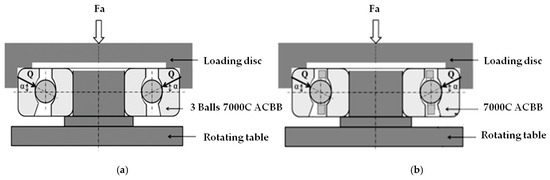
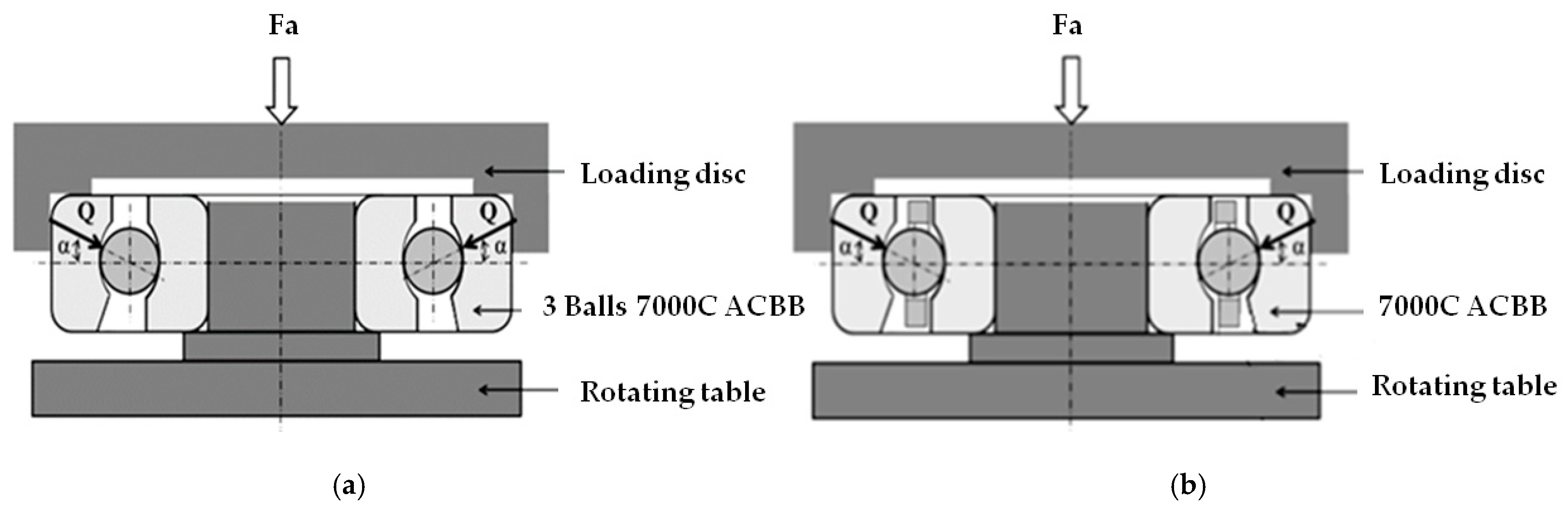
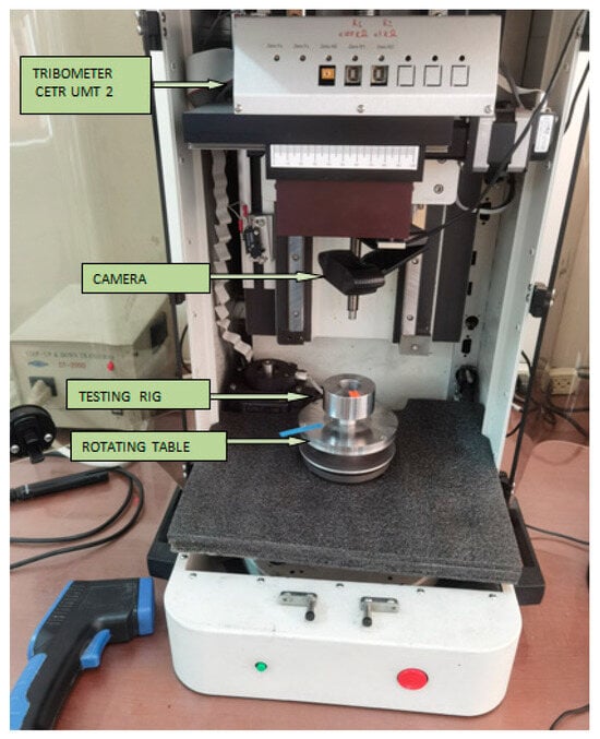
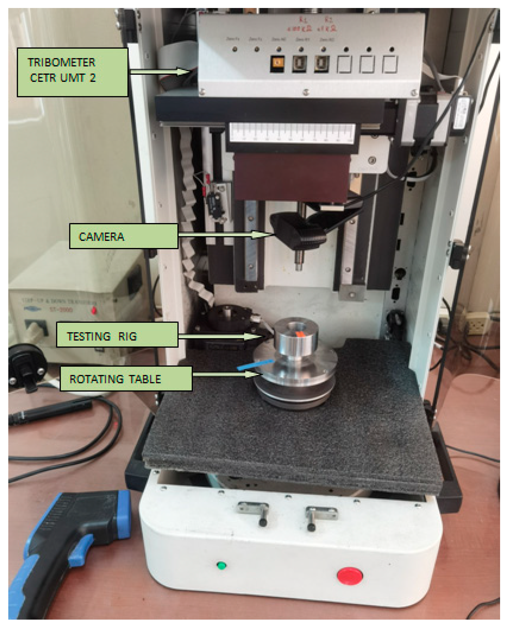
The test rig consists of a modified 7000C angular contact ball bearing (ACBB) with the inner ring mounted on a shaft and a loading disc on the outer ring. The shaft is attached to the rotating table of the CETR UMT-2 Tribometer (Bruker Corporation, Campbell, CA, USA, 2008), as shown in Figure 1. The outer ring and the attached loading disc are free and can be rotated only by the friction forces developed at the ball–outer raceway contacts.
Figure 1.
The schematic view of the test rig with 7000C ACBB mounted: (a) with three balls without a cage and (b) 4, 6 and 8 balls with a cage.
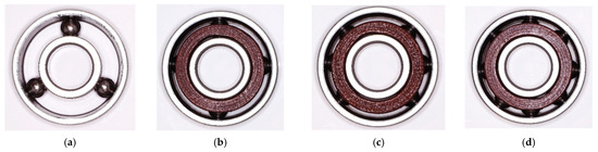
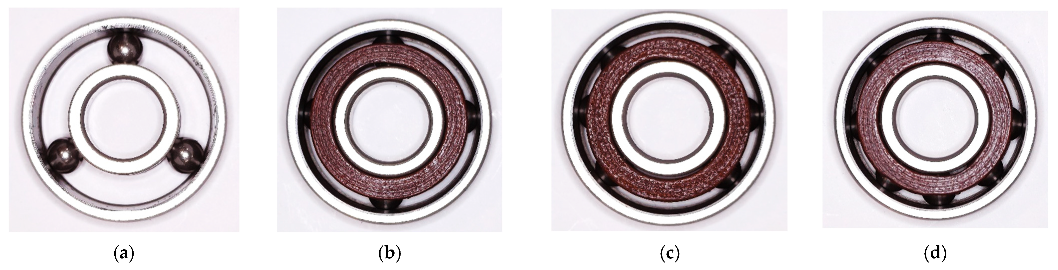
The following four modifications were performed on the standard 7000C ACBB [1]. The first tests were conducted using only three balls without a cage. The three balls were placed equidistantly at 120 degrees and mounted in the ACBB. The next tests were carried out with 4, 6 and 8 balls, separated by a phenolic cage, as shown in Figure 2.
Figure 2.
The positions of 3, 4 and 6 balls in a modified 7000C ACBB, as shown by (a), (b), and (c), respectively, compared with a standard one with 8 balls (d).
The characteristics of the standard 7000C ACBB are presented in Table 1. The external diameter, the internal diameter, the number of balls, the contact angle and the cage composition are presented in the catalogue. To determine the ball diameter, the 7000C ACBB was disassembled. The inner diameter of the cage and the guiding diameter of the inner ring were measured. Both the inner and outer race conformities, fi and fe, and the transversal radius, ri,o, respectively, were measured using the Taylor Hobson profilometer (Form Talysurf Intra series: M112/3344-02). The conformities fi,o were determined as the ratio between the measured transversal radii ri,e and the ball diameter db.
Table 1.
The dimensional characteristics of the standard 7000C ACBB.
The tested rig mounted on the CETR UMT-2 Tribometer is presented in Figure 3.
Figure 3.
A general view of the CETR UMT-2 Tribometer and the testing rig with a 7000C ball bearing.
The angular rotation of the table and the disc was monitored using a camera. The rotation of the tribometer table was established for each test at the following values: 100, 200, 300, 400 and 500 rpm.
An axial load of Fa = 3.11 N was generated on the ACBB by the disc mounted on the outer race. Depending on the number of balls mounted in the ball bearing, the normal load on each ball varied and was determined according to the following relation:
where Z is the number of balls in each experiment, and α is the real contact angle under axial load. According to Harris’s methodology [11], the real contact angle was calculated. The actual values of the contact angle vary between 15.6 degrees for 3 balls and 15.32 degrees for 8 balls. Since the contact angle increases with a maximum of 4% from the initial value, the calculation of the normal load Q was performed using the initial value of 15 degrees. Both the dimensions of contact ellipses and the Hertzian contact pressure at the ball–raceway contacts vary as a function of the number of balls. The semimajor axes of the contact ellipses between the balls and raceways varied between 0.16 mm for 3 balls and 0.11 mm for 8 balls.
In all the tests, SAE 5W-30 oil was used as the lubricant, with the properties presented in Table 2.
Table 2.
The properties of the SAE 5W-30 oil.
2.2. Experimental Procedure
2.2.1. Experimental Procedure for Testing 7000C ACBB with 3 Balls
The standard 7000C ACBB was disassembled, the phenolic cage was removed, and only three balls were mounted between the inner and outer raceways. The angular position of 120 degrees for each ball was verified. The inner ring was mounted on the rotating table of the Tribometer, and a loading disc was mounted on the outer ring. The modified 7000C ACBB was lubricated and was rotated at the imposed rotational speeds. Due to the internal ball–raceway–lubricant resistance, both the outer ring and the loading disc start to rotate until they reach the speed of the inner ring. At this moment, the rotation of the inner ring was suddenly stopped, and the rolling bearing operated as a ball bearing with the outer ring rotating and the inner ring fixed, due to inertia, until it stops. As the three balls had the same normal load, Q = Fa/(3 × sin(α)), they rolled on the raceways maintaining their positions, with an angular speed ωc = ω0·(1 + γ)/2. During the deceleration process, the following dynamic equilibrium equation for the outer ring and the loading disc was considered:
where J is the moment of inertia of the rotating mass and the outer race of the ACBB, and Texp(ω) is the experimental friction torque generated in the modified ACBB for the imposed angular speed ω. Based on previous experiments [16,17], the experimental friction torque can be expressed as a power function of the angular speed ω as in the following relation:
where K is a constant depending on the lubricant viscosity, load, and geometry, and n is an exponent less than one (n < 1).
As presented in the References Section [16,17], at low axial loads, the friction torque is predominantly dependent on the hydrodynamic lubrication forces on the inner and outer ball–raceway contacts.
As will be shown in Section 4, the hydrodynamic lubrication forces depend on the speed parameter U to a power less than 1 (0.636). Since the speed parameter U is directly proportional to the angular speed ω, the friction torque follows a power-law dependence on the angular speed ω and can be approximated by Equation (3) if other minor friction components are neglected.
Considering Equations (2) and (3), the following differential equation results are as follows:
Equation (4) was analytically solved, and the variation in the angular speed ω(t) and the variation in the angular position Φ(t) as a function of time were determined by two nonlinear equations [17].
The following conditions were imposed initially: at t = 0 (starting the deceleration process), ω = ω0, t = t0 (stop of the decelerating process), Φ(t0) = Φ0 and ω = 0. The constant K and exponent n were obtained by solving the following nonlinear equations:
Both the total time of the decelerating process, t0, in seconds and the total angle of the outer race and disc rotation, Φ0, in radians, were quantified by the camera and serve as input data for solving Equations (5) and (6).
To solve nonlinear Equations (5) and (6), the authors developed a Python-based programme and determined parameters K and n for each rotational speed and, finally, determined Texp. The developed Python script includes a dedicated numerical module for solving the nonlinear system of Equations (5) and (6) for each experimental dataset. The program automatically determines the parameters K and n by iterative fitting and computes the corresponding experimental torque Texp.
The solver module implements a fully analytical algorithm for determining the friction torque model parameters K and n for each experimental measurement. Taking ω0 as the initial input angular velocity, t0 as the deceleration time, and ϕo ϕ0 as the total angular displacement, the exponent n is computed directly from a closed-form expression derived from Equation (4), which describes the motion of the decelerating system. Numerical safeguards are applied to ensure that n remains within physically meaningful bounds (n < 1). The coefficient K is subsequently determined explicitly from the known moment of inertia J of the rotating assembly and the previously computed exponent n. The experimental friction torque Texp is then evaluated directly from the identified model parameters. Finally, the goodness of fit is quantified through the coefficient of determination R2 (R-squared), which is computed by comparing the model predictions against the experimental data points.
2.2.2. Experimental Procedure for Testing 7000C ACBB with 4, 6 and 8 Balls
The testing of the modified 7000C ACBB with 4 balls and a cage consists of removing the four balls from the standard ACBB so that the remaining 4 balls are positioned at 90 degrees, as seen in Figure 2b. The experimental procedure and equations are similar to those in Section 2.2.1.
The testing of the modified 7000C ACBB with 6 balls and a cage was performed by removing 2 opposite balls from the standard ACBB, as shown in Figure 2c. A similar procedure and relations to those in Section 2.2.1 have been considered. Finally, the standard 7000C ACBB was tested with 8 balls and a cage using the same procedure and equations as Section 2.2.1.
For each rotational speed, three tests were performed, obtaining three values for Φ0 and t0. To solve Equations (5) and (6), the average values were used in the above-mentioned programme as input data.
3. Results
The experiments were carried out at the following rotational speeds: 100, 200, 300, 400, and 500 rot/min. During the experiments, the laboratory temperature was approximately 23 to 24 °C, and the temperature of the tested ball bearing increased to 26–27 °C. The inertia moment of the loading disc and the outer ring was J = 1.197 × 10⁻⁴ kg·m2.
A graphical user interface was implemented in the programme to facilitate the data import from the CSV files and to visualise the computed results. The program also generates the PDF tables and logarithmic plots of Texp = K·ωn for each tested speed, ensuring a fully automated and reproducible workflow.
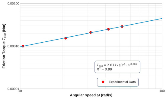
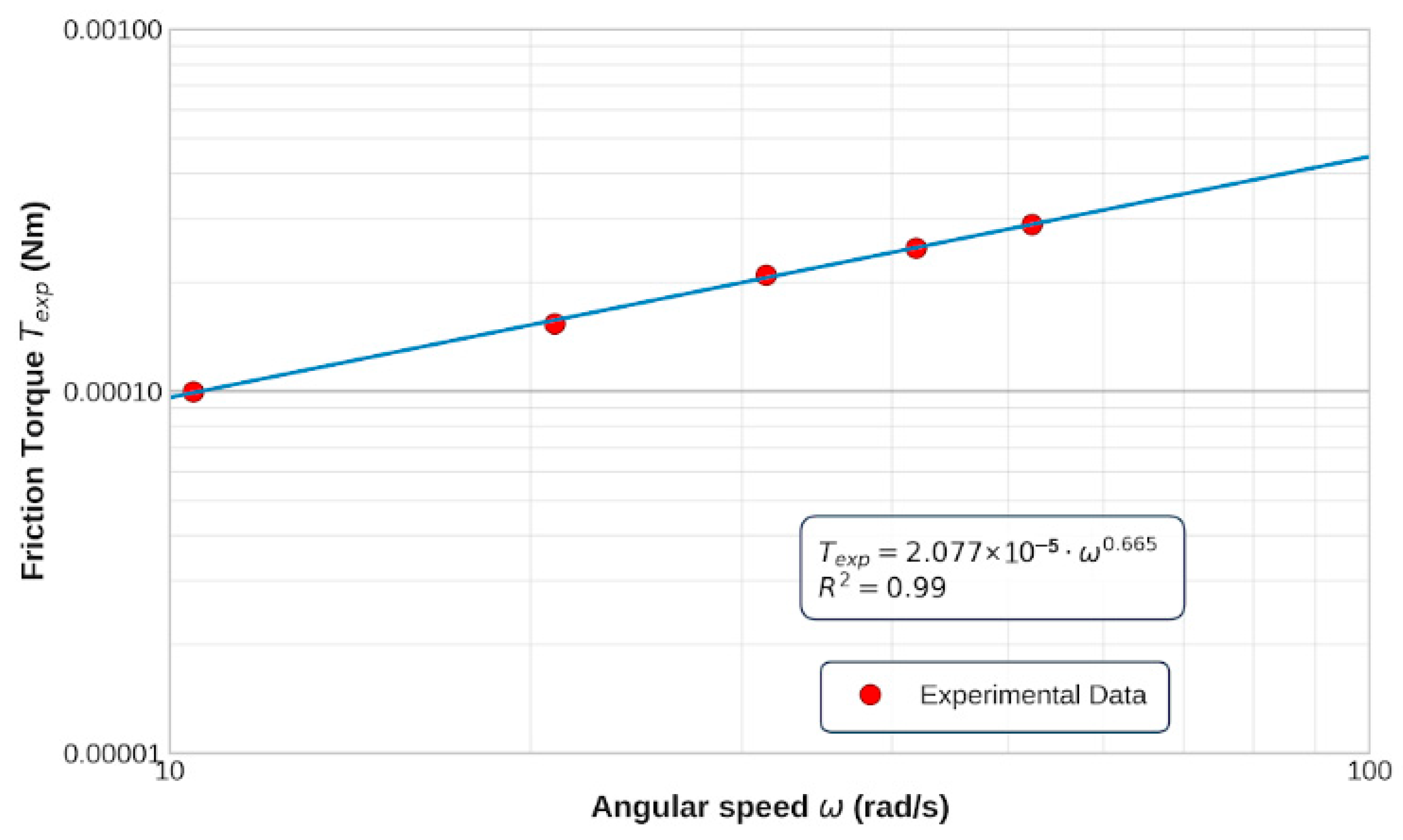
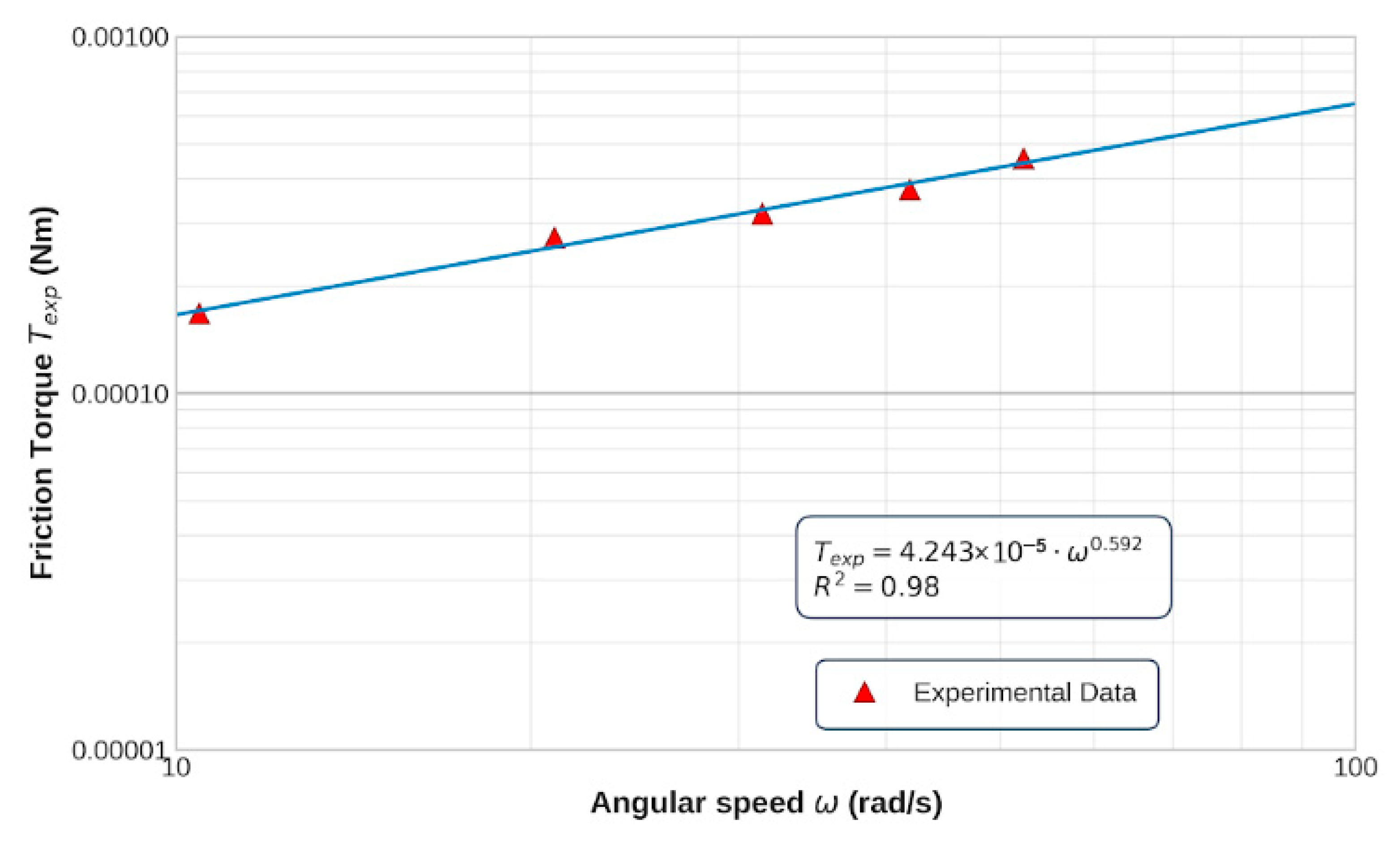
The measured parameters N, ωo, to and Φo were included as input data for each rotational speed and modified variant. The parameters K, n and the friction torque Texp were presented as output data. Table 3 and Table 4 present the average input and output results for the 7000C ACBB with three balls and without a cage. Figure 4 presents the variation in the average experimental friction torque as a function of angular speed ω for the 7000C ACBB with three balls without a cage.
Table 3.
The input data for three balls without a cage.
Table 4.
The output data for three balls without a cage.
Figure 4.
The variation in the average friction torque with angular speed for the modified 7000C ACBB with three balls without a cage.
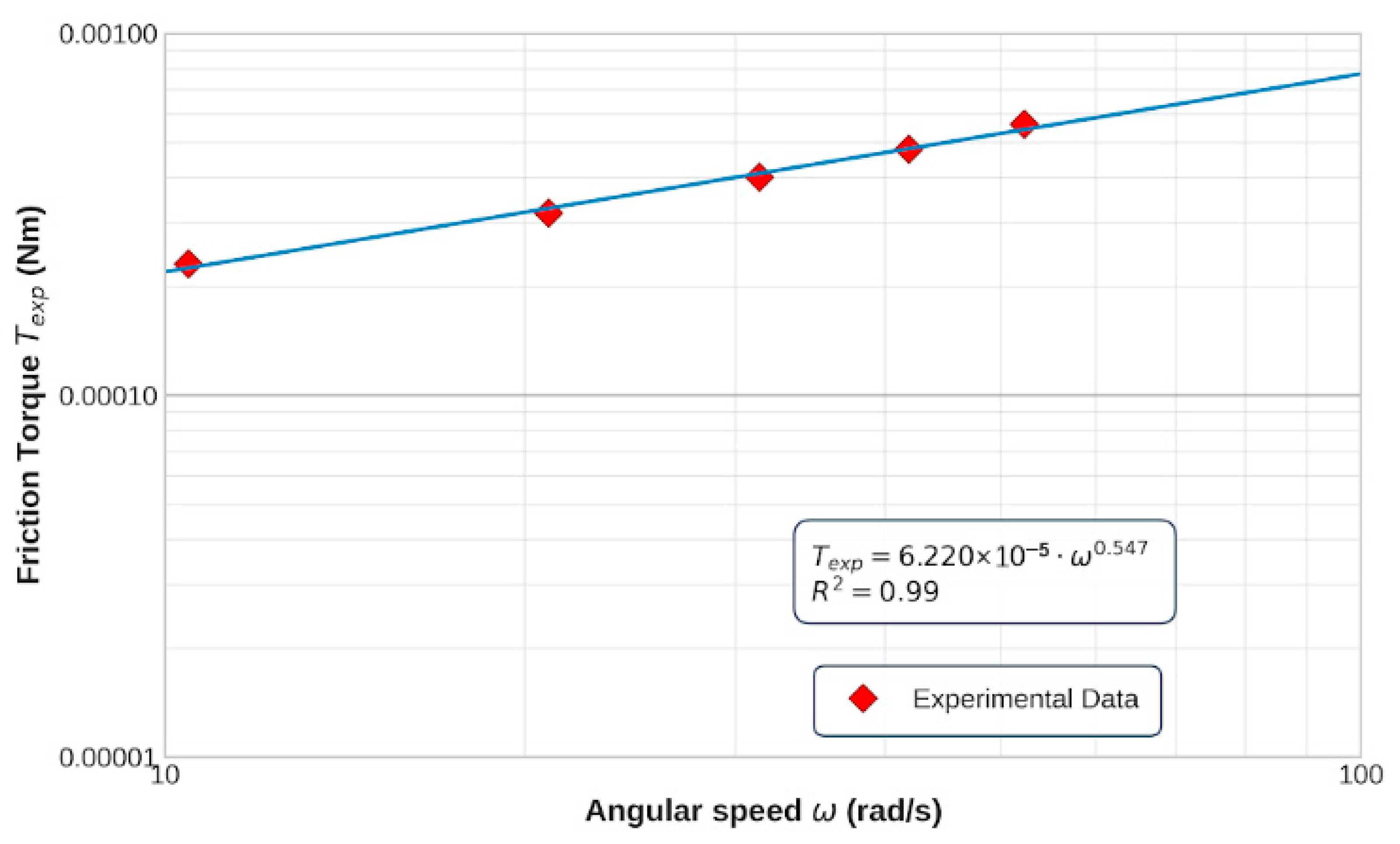
Table 5 and Table 6 present the average input and output results for the 7000C ACBB with four balls and a cage. Figure 5 presents the variation in the average experimental friction torque as a function of angular speed ω for the 7000C ACBB with four balls and a cage.
Table 5.
The input data for four balls and a cage.
Table 6.
The output data for four balls and a cage.
Figure 5.
The variation in the average friction torque with angular speed for the modified 7000C ACBB with four balls and a cage.
Table 7 and Table 8 present the average input and output results for the 7000C ACBB with six balls and a cage. Figure 6 presents the variation in the average experimental friction torque as a function of angular speed ω for the 7000C ACBB with six balls and a cage.
Table 7.
The input data for six balls and a cage.
Table 8.
The output data for six balls and a cage.
Figure 6.
The variation in the average friction torque with angular speed for the modified 7000C ACBB with six balls and a cage.
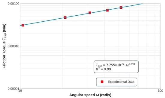
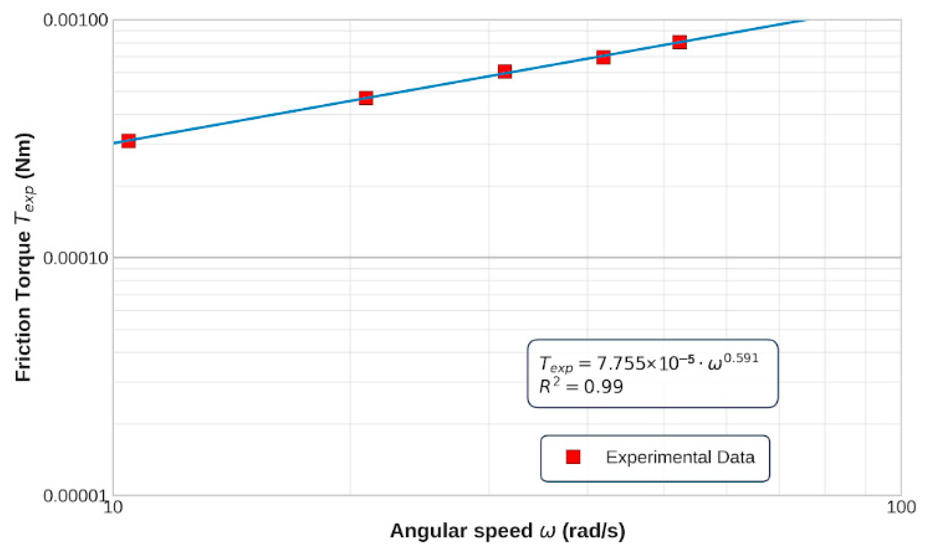
Table 9 and Table 10 present the average input and output results for the 7000C ACBB with eight balls and a cage. Figure 7 presents the variation in the average experimental friction torque as a function of angular speed ω for the 7000C ACBB with eight balls and a cage.
Table 9.
The input data for eight balls and a cage.
Table 10.
The output data for eight balls and a cage.
Figure 7.
The variation in the average friction torque with angular speed for the standard 7000C ACBB with eight balls and a cage.
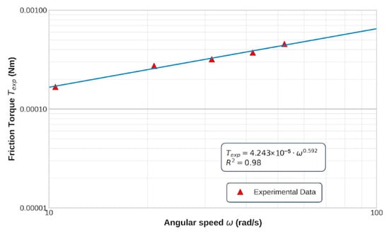
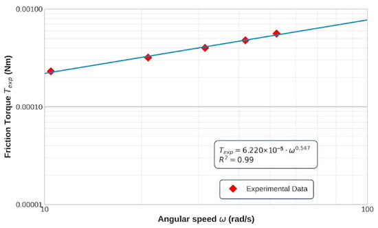
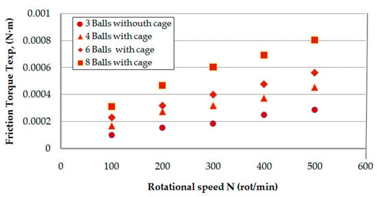
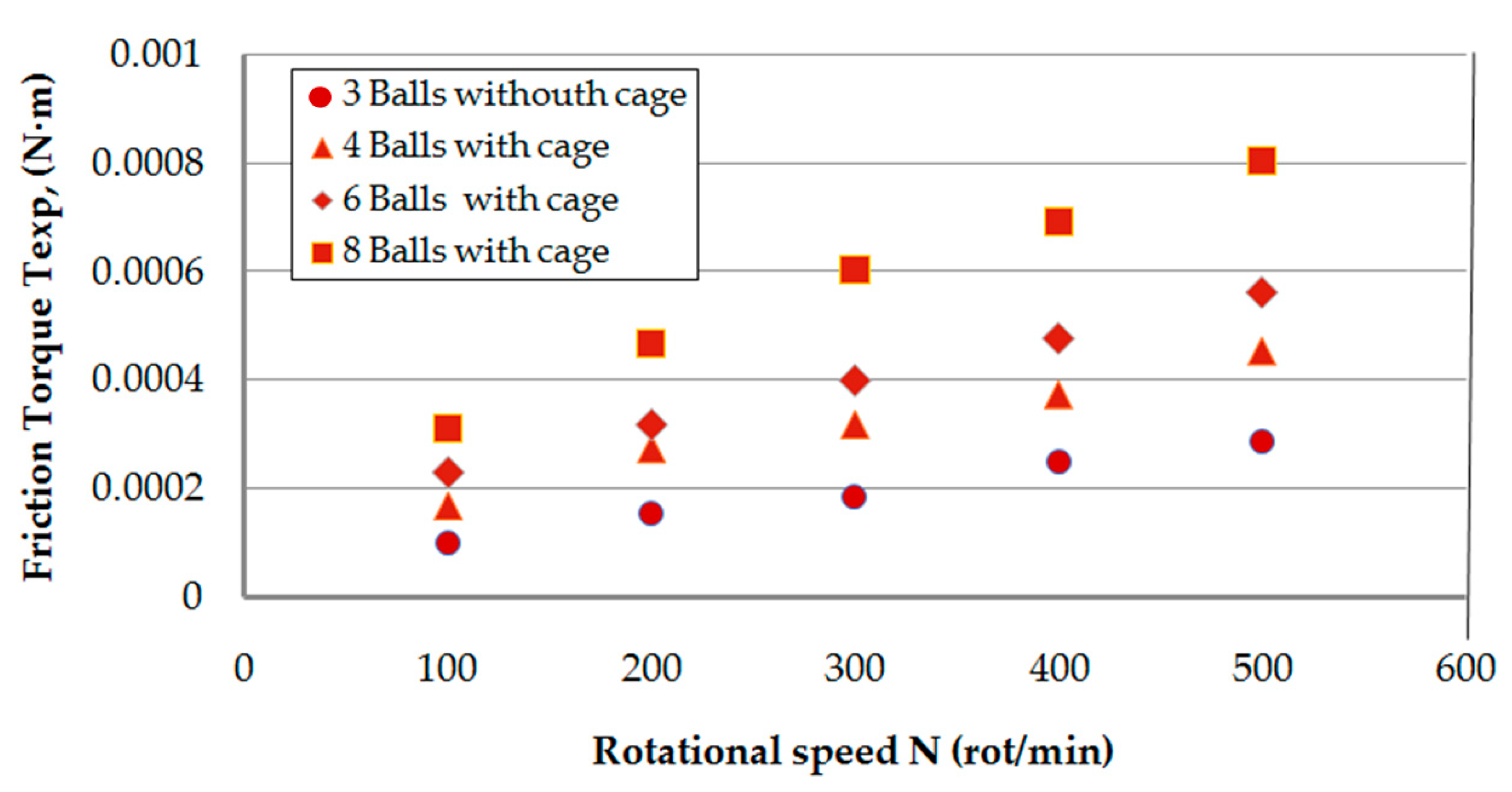
It can be observed that for all four cases, a power-law dependence between the average experimental friction torque and angular speed, according to Equation (3), has been obtained. The constant K have values between 2 × 10⁻⁵ for three balls without a cage and 8 × 10⁻⁵ for the standard ACBB with eight balls and a cage. Also, the exponent n varies between 0.54 and 0.59. This good correlation between the experiment and the proposed power function for the experimental friction torque suggests that the most important contribution of the cage presence with four, six and eight balls to the experimental friction torque is attributed to the hydrodynamic resistance in the ball–race contacts. The average experimental values of the friction torque, Texp, for all four cases and for each rotational speed are presented in Table 4, Table 6, Table 8 and Table 10, for three, four, six and eight balls, respectively. A centralised presentation of the variation in the average experimentally determined friction torque for the four cases above is presented in Figure 8. It can be observed that the introduction of the cage, combined with the increase in the number of balls, leads to an increase in the friction torque, although normal forces on the balls decrease according to Equation (1). As will be demonstrated in the next paragraph, under low axial loads, the components of the friction generated by normal loads in ball–race contacts make an insignificant contribution compared to the hydrodynamic rolling resistance.
Figure 8.
The variation in the average friction torque with rotational speed for the modified 7000C ACBB, having three, four, six and a standard 7000C ACBB with eight balls.
4. Theoretical Models
4.1. General Model for Friction Torque in an ACBB
The complex methodology developed by Houpert [13] to determine the friction torque in an ACBB includes: the friction components generated by hydrodynamic rolling resistance, curvature effects, elastic rolling resistance, pivoting effects and additional braking effects caused by the cage. The model has been included in the following general equation [13]:
where Z is the number of balls, FRo,i are the hydrodynamic rolling forces in the ball–race contacts, MCo,i are the curvature friction moments developed in the ball–race contacts, MERo,i are the rolling resistance moments in the ball–race contacts as result of elastic rolling hysteresis, and MPo,i are the pivoting moments between the balls and races on contact ellipses. MB and FB are the brake moments and are the contact forces developed in the ball–cage contacts, respectively.
The normal loads on the balls varied with the number of balls, between 3.93 N for three balls and 1.43 N for eight balls. As a result of these small forces, the semimajor contact ellipses between balls and raceways varied between 0.16 mm for three balls and 0.11 mm for eight balls. The components of the friction torque generated by MCo,i, MERo,i and MPo,i have a value of magnitude order of 10−6 N·m and were neglected in Equation (7). With these simplifications, Equation (7) can be expressed as follows:
- (i)
- For three balls without a cage, Equation (7) becomes:
- (ii)
- For four, six and eight balls with a cage, Equation (7) becomes:
Hydrodynamic rolling resistance developed in the outer and inner races of the ball, FRo and FRi, respectively, is determined by Biboulet and Houpert’s equations [18]:
where E* is the reduced Young modulus of the ball and races, Uo,i and Wo,i are the classical dimensionless speed and load parameters, respectively, which are determined for the outer and inner ball–race contacts.
Ri and Ro are the radii of inner and outer races, respectively, and are determined by the following equation:
where dm is the pitch diameter of the ball bearing and γ is given by the equation:
The ratios of the equivalent radii for the inner and outer races are determined by the following relations [13]:
Ry,o,i are the equivalent of the ball–race radius in the rolling direction and are determined by relations:
4.2. Friction Torque Component Generated by Cage
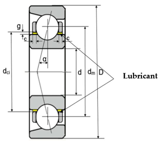
As is presented in Figure 9, the cage is guided on the inner race of 7000C ACBB with a radial clearance of g and on two circular surfaces with a width of c.
Figure 9.
The view of the guidance cage on the inner ring.
During the rotating outer race in the decelerating process, the cage and the Z balls have an angular speed determined by relation [19]:
The tangential speed at the ball’s centre is obtained by the relation:
Considering the Newtonian behaviour of the oil and the constant film between the cage and the inner guidance ring, the tangential stress τ in the cage–race interstice can be obtained with the relation:
The resistant moment between the cage and the guided inner ring, Mc, can be expressed by the relation:
Considering that the resistance moment, Mc, is taken over by the Z balls, the normal contact force between the ball and the cage is obtained by the following relation:
The friction moment between the ball and the cage is obtained by the relation:
In the simulation process, the following dimensional values have been considered:
c = 1.5 mm, g = 0.15 mm, and dci = 14.49 mm and a friction coefficient of µc = 0.05 was considered for the ball–cage lubricated contacts.
According to Equation (9), the component of the friction torque generated by a cage can be expressed by the following relation:
4.3. Simulation Results
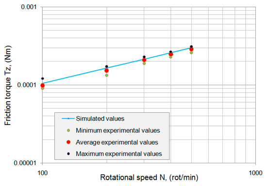
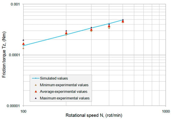
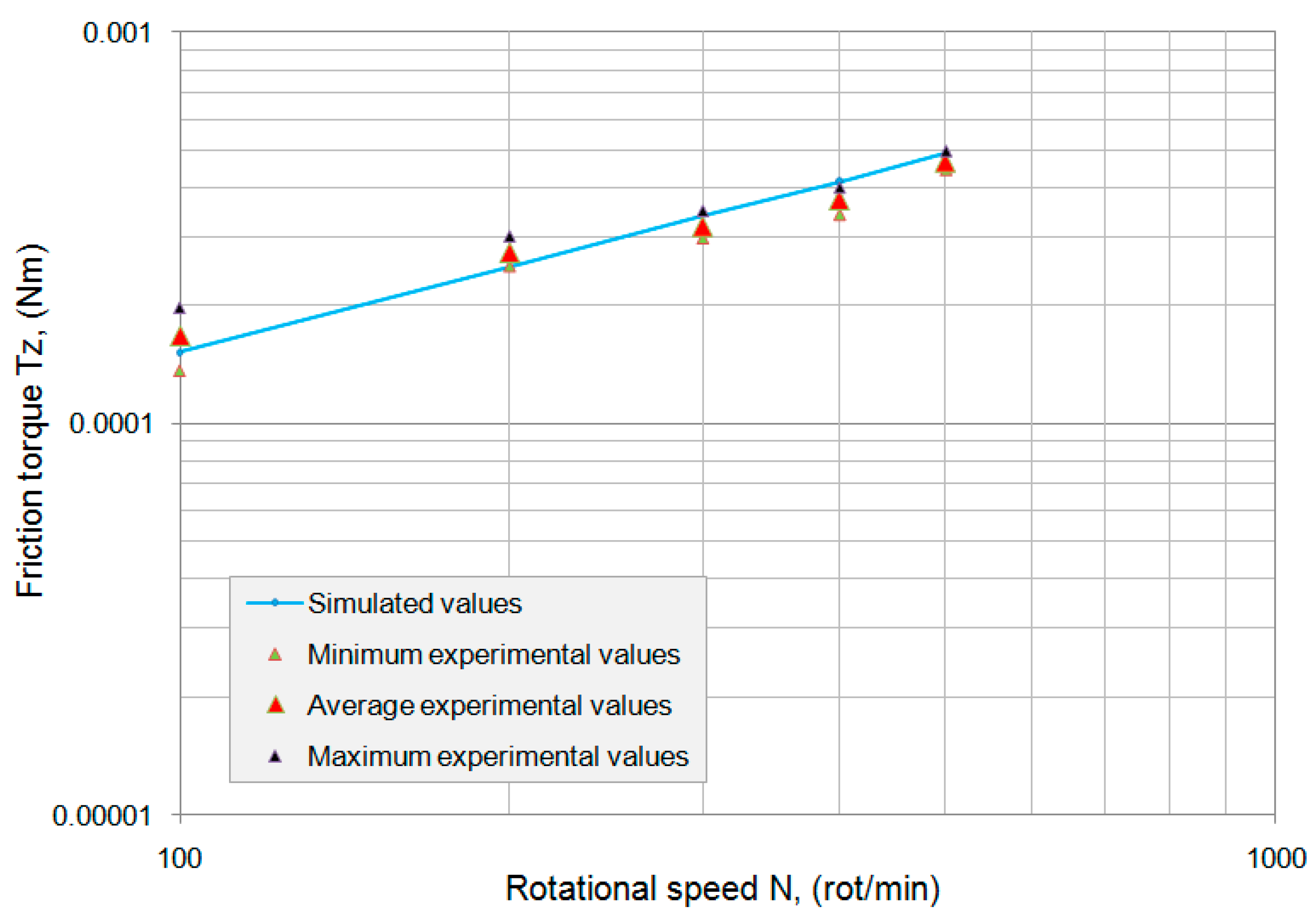
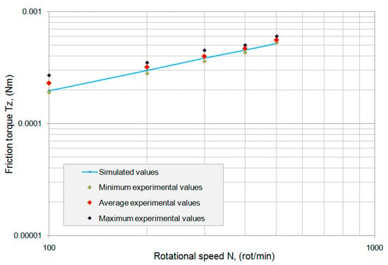
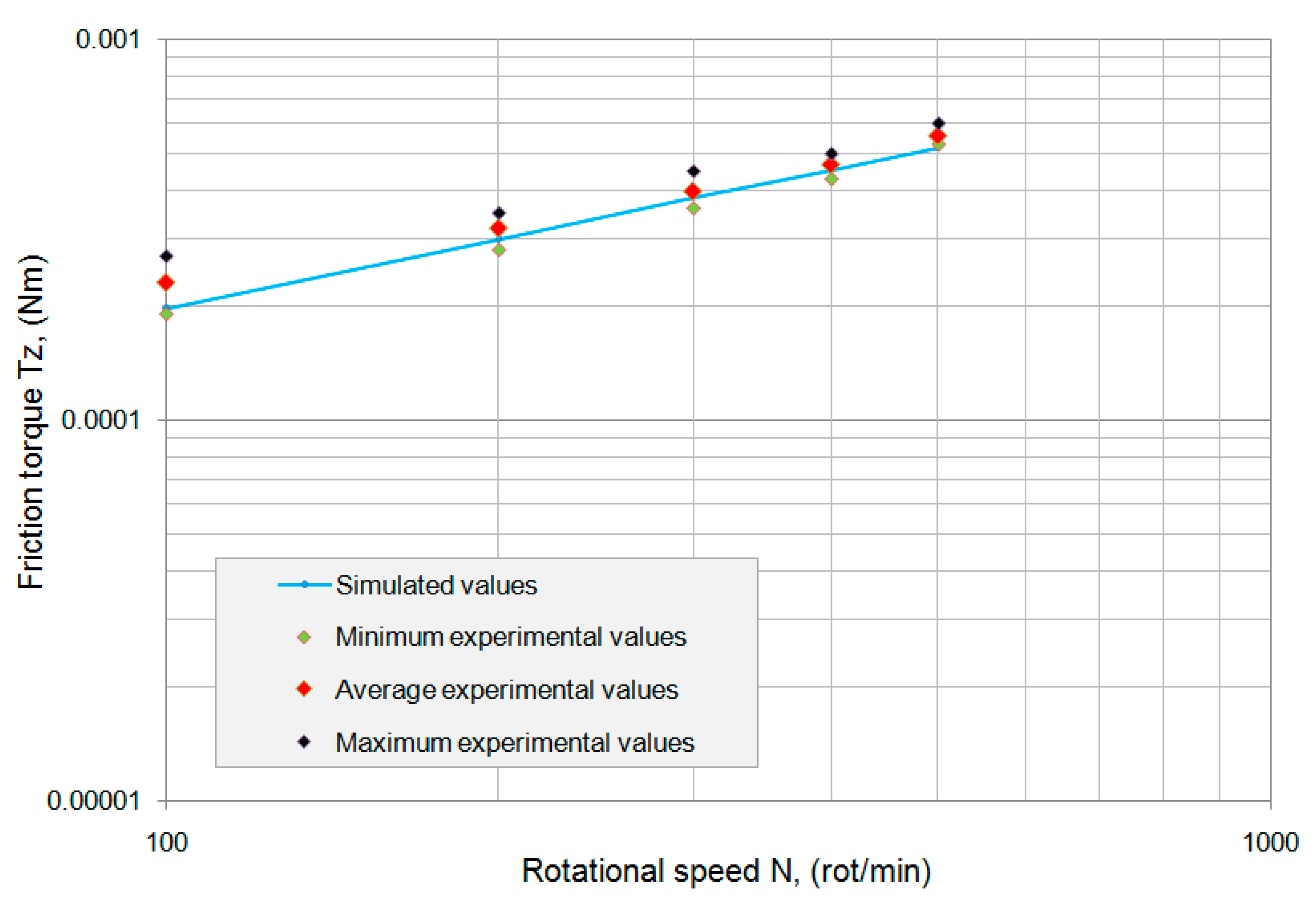
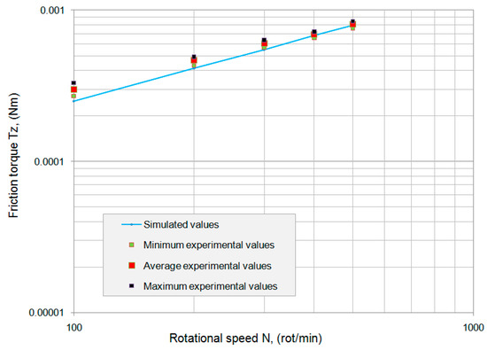
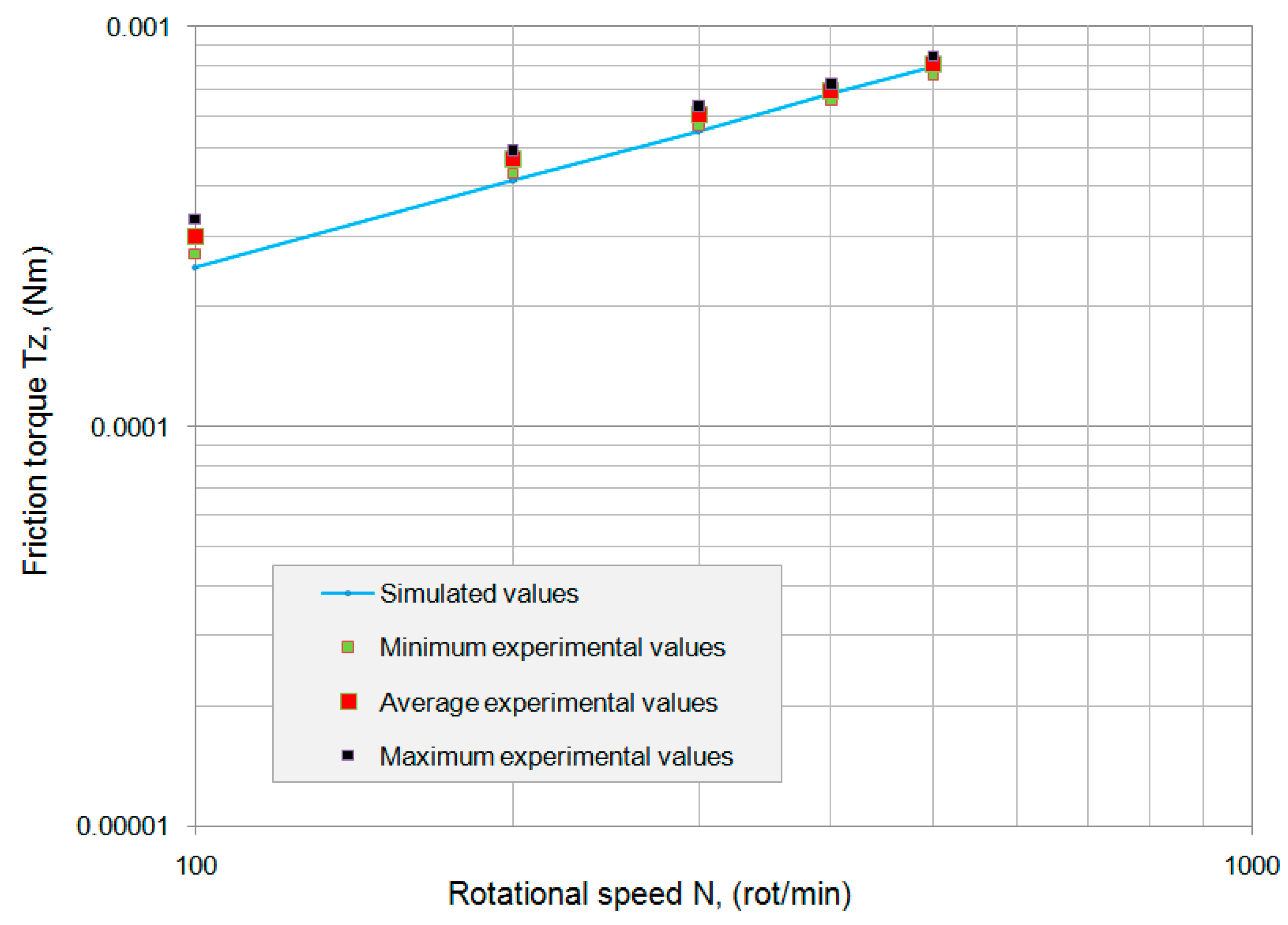
A computer program to determine the friction torques, solving both Equations (8) and (9) for both three balls without a cage and for four, six and eight balls with a cage, has been developed. The oil kinematic viscosity during the test’s temperature of 26–27 °C was determined with the Khonsary and Booster [20] methodology, and the values of (118–113) mm2·s−1 were obtained. Because the oil density is 850 kg·m−3, the dynamic viscosity η varies between 0.1 and 0.096 Pa·s. The simulated friction torques for three, four, six and eight balls have been presented in the logarithmic diagrams in Figure 10, Figure 11, Figure 12 and Figure 13.
Figure 10.
The correlation between the simulated friction torque and the experimental values for the modified 7000C ACBB with three balls without a cage.
Figure 11.
The correlation between the simulated friction torque and the experimental values for the modified 7000C ACBB with four balls and a cage.
Figure 12.
The correlation between the simulated friction torque and the experimental values for the modified 7000C ACBB with six balls and a cage.
Figure 13.
The correlation between the simulated friction torque and the experimental values for the standard 7000C ACBB with eight balls and a cage.
To evidence the dispersion of the experimental values for the three tests, the maximum and minimum friction torque values were determined. These values, together with the average experimental values for the friction torque, were included for comparison with the simulated values in the diagrams corresponding to Figure 10, Figure 11, Figure 12 and Figure 13.
Comments:
- (i)
- The dispersion of the experimental values for the friction torque varied between 8% and 18%, and the maximum dispersion was obtained at a rotational speed of 100 rot/min, for all cases;
- (ii)
- The dispersion between the average experimental friction torque and the simulated values varied between 5% and 15%.
As a first conclusion, the simulation of the friction torque considering hydrodynamic rolling resistance as a dominant contribution can be accepted for a miniature ball bearing with a low axial load.
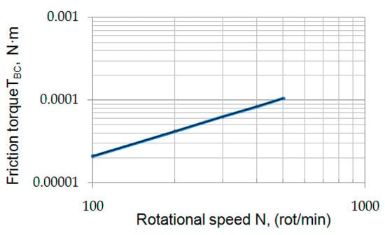
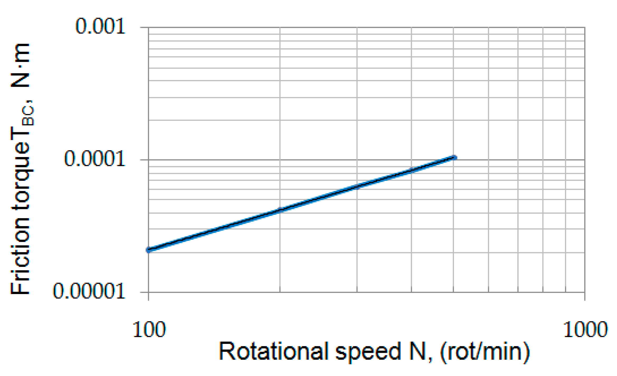
The contribution of the cage to the total friction torque TBC has been simulated and is presented in Figure 14. According to Equations (18)–(21) in the actual proposed model, the component TBC does not depend on the number of balls, having a similar variation in rotational speed for four, six and eight balls. For a constant axial force, Fa, an increase in the number of balls leads to a reduction in the contact force between the balls and the cage, FB, and maintains a constant total friction component, TBC.
Figure 14.
The variation in the friction torque component generated by the presence of the cage in a 7000C ball bearing.
From Figure 13 and Figure 14, it can be concluded that for the standard 7000C ball bearing, the friction torque generated by the cage represents between 8% and 12.5% of the total friction torque within the rotational speed used. By reducing the number of balls to six and four, the contribution of the friction moment generated by the cage increases to 18% and 22% from the total friction torque, respectively.
5. Conclusions
The authors experimentally and theoretically evaluated the influence of the cage on the total friction torque in a miniature oil-lubricated 7000C ACBB. Four cases of the modified 7000C ball bearings have been considered in experiments and in simulations: a modified ball bearing by using only three equidistant balls with the elimination of the cage; two modified ball bearings, including the cage with four and six balls; and a standard 7000C with eight balls and the cage.
The friction torque was determined in lubricated conditions using the spin-down methodology with an axial load of 3.11 N and the rotation speed range between 100 and 500 rot/min.
The most important conclusions drawn from our work are as follows:
- (1)
- In the absence of the cage, by using only three balls, the minimum values of the friction torque were only obtained as a result of the hydrodynamic rolling resistances between the balls and raceways.
- (2)
- Including the cage with four balls leads to an increase in the total friction torque by 60–65 percent compared to the torque achieved with three balls without a cage. By further increasing the number of balls to six and eight, the frictional torque increased by 35–40 percent, with each increase seen in the number of balls.
- (3)
- The friction torque component generated by the presence of the cage does not depend on the number of balls but only on the rotational speed.
- (4)
- Increasing the number of balls in the ball bearing cage leads to an increase in the friction torque as a result of an increase in the number of hydrodynamic rolling resistances between the balls and the raceways.
As a general conclusion, for miniature low-loaded angular contact ball bearings, the most important contribution to the friction torque is given by the hydrodynamic rolling resistance that is generated in the ball–raceway contacts.
Author Contributions
Conceptualisation, D.O.; methodology, A.C.D. and D.C.; software, A.Z.; validation, D.O., V.C. and D.C.; formal analysis, D.O.; investigation, D.C.; resources, D.C.; data curation, A.Z.; writing—original draft preparation, V.C.; writing—review and editing, V.C. and D.O.; visualisation, D.C.; supervision, D.O. All authors have read and agreed to the published version of the manuscript.
Funding
This research received no external funding.
Data Availability Statement
The data are available on request.
Acknowledgments
This paper was supported by the Mechanical Engineering Doctoral School of “Gheorghe Asachi” Technical University, Iaşi.
Conflicts of Interest
The authors declare no conflicts of interest.
References
- SKF Rolling Bearings Catalogue. Available online: https://cdn.skfmediahub.skf.com/api/public/0901d196802809de/pdf_preview_medium/0901d196802809de_pdf_preview_medium.pdf (accessed on 1 February 2026).
- Schaeffler.Com. Available online: https://schaeffler-publications.com/hr-1-en.html (accessed on 1 February 2026).
- NTNglobal.Com. Available online: https://www.ntnbearing.in/catalog/2202E_all.pdf (accessed on 1 February 2026).
- Harris, T.A.; Kotzalas, M.N. Rolling Bearing Analysis. In Advanced Concepts of Bearing Technology, 5th ed.; CRC Press: New York, NY, USA, 2007. [Google Scholar]
- Yang, Z.; Yu, T.; Zhang, Y.; Sun, Z. Influence of cage clearance on the heating characteristics of high-speed ball bearings. Tribol. Int. 2017, 105, 125–134. [Google Scholar] [CrossRef] [Scilit]
- Chen, H.; Liu, Y.; Liang, H.; Zhang, H.; Wang, W. The cage instability of angular contact ball bearing under high speed conditions. Mech. Mach. Theory 2024, 197, 105646. [Google Scholar] [CrossRef] [Scilit]
- Brecher, C.; Hassis, A.; Rossaint, J. Cage Friction in High-Speed Spindle Bearings. Tribol. Trans. 2014, 57, 77–85. [Google Scholar] [CrossRef] [Scilit]
- Choe, B.; Lee, J.; Jeon, D.; Lee, Y. Experimental study on dynamic behavior of ball bearing cage in cryogenic environments, Part I: Effects of cage guidance and pocket clearances. Mech. Syst. Signal Process. 2019, 115, 545–569. [Google Scholar] [CrossRef] [Scilit]
- Gupta, P.K. Advanced Dynamics of Rolling Elements, 1st ed.; Springer: New York, NY, USA, 1984. [Google Scholar]
- Meeks, C.R.; Ng, K.O. The Dynamics of Ball Separators in Ball Bearings—Part I: Analysis. ASLE Trans. 1985, 28, 277–287. [Google Scholar] [CrossRef] [Scilit]
- Cao, H.; Niu, L.; Xi, S.; Chen, X. Mechanical model development of rolling bearing-rotor systems: A review. Mech. Syst. Signal Process. 2018, 102, 37–58. [Google Scholar] [CrossRef] [Scilit]
- Houpert, L.; Leenders, P. A Theoretical and Experimental Investigation into Rolling Bearing Friction. In Proceedings of the Eurotrib Conference, Lyon, France, 9–12 September 1985. [Google Scholar]
- Houpert, L. Numerical and Analytical Calculations in Ball Bearings. In Proceedings of the 8th European Space Mechanism and Tribology Symposium Toulouse, Colmar, France, 29 September–1 October 1999. [Google Scholar]
- Houpert, L. Ball Bearing and Tapered Roller Bearing Torque: Analytical, Numerical and Experimental Results. STLE Tribol. Trans. 2002, 45, 345–353. [Google Scholar] [CrossRef] [Scilit]
- Russell, T.; Sadeghi, F. The effect of lubricant starvation on ball bearing cage pocket friction. Tribol. Int. 2022, 173, 107630. [Google Scholar] [CrossRef] [Scilit]
- Olaru, D.; Stamate, C.; Dumitrascu, A.; Prisacaru, G. New micro tribometer for rolling friction. Wear 2011, 271, 842–852. [Google Scholar] [CrossRef] [Scilit]
- Olaru, D.N.; Bălan, M.R.D.; Tufescu, A.; Cârlescu, V.; Prisacaru, G. Influence of the cage on the friction torque in low loaded thrust ball bearing operating in lubricated conditions. Tribol. Int. 2017, 107, 294–305. [Google Scholar] [CrossRef] [Scilit]
- Biboulet, N.; Houpert, L. Hydrodynamic force and moment in pure rolling lubricated contacts: Part II, point contacts. Proc. Inst. Mech. Eng. Part J-J. Eng. Tribol. 2010, 224, 777–787. [Google Scholar] [CrossRef] [Scilit]
- Harris, T.A. Rolling Bearing Analysis, 4th ed.; John Wiley & Sons, Inc.: Hoboken, NJ, USA, 2001. [Google Scholar]
- Khonsary, M.N.; Booser, E.R. Applied Tribology. In Bearing Design and Lubrication, 3rd ed.; Wiley: Hoboken, NJ, USA, 2017. [Google Scholar]

Disclaimer/Publisher’s Note: The statements, opinions and data contained in all publications are solely those of the individual author(s) and contributor(s) and not of MDPI and/or the editor(s). MDPI and/or the editor(s) disclaim responsibility for any injury to people or property resulting from any ideas, methods, instructions or products referred to in the content. |
© 2026 by the authors. Licensee MDPI, Basel, Switzerland. This article is an open access article distributed under the terms and conditions of the Creative Commons Attribution (CC BY) license.