


Abstract
With the opening of complex service routes, the importance of the service performance of brake pads under long slope braking conditions is increasing. It is necessary to analyze the slope braking adaptability of current brake pad products. This work takes the copper-based powder metallurgy brake pads of a certain in-service high-speed train as the research object and conducts friction and wear behavior tests of the brake pads based on a full-scale brake test bench. Through microscopic observation and damage analysis, the differences in friction and wear behavior of the brake pads under stop braking and slope braking conditions are compared, revealing the wear mechanism and damage evolution characteristics of the brake pads. The results show that under the impact of high speed, high braking force, and severe thermal load in the stop braking conditions, the uneven wear of brake pads is high, and the eccentric wear of friction blocks is affected by both the friction radius and friction direction. The friction surface has a large number and size of damages, and the stability of the friction interface is poor. The brake pad exhibits a composite wear mechanism dominated by abrasive wear and brittle fracture induced exfoliation. In the slope braking condition, under the action of low speed, low braking force, and long-term stable thermal load, the uneven wear of the brake pads is relatively low, the surface damage size is small, and the friction block only has eccentric wear along the friction direction. The brake pad mainly initiates cracks along the interface of the components, which propagate parallel to the friction surface, exhibiting a progressive delamination and flaking exfoliation mechanism with a low wear rate. Although the friction interface of the brake pad is relatively stable under slope braking conditions, the cumulative delamination wear of the brake pads under long-term braking action needs further attention.
1. Introduction
The service performance of brake pads is crucial for the safety of train operation [1,2,3]. With the rapid development of high-speed railway technology, the running speed of trains is getting higher and higher, reaching up to 380 km/h [4,5]. Whether safe parking can be achieved at high speeds is a key indicator that restricts the development of high-speed trains [6]. Generally speaking, stop braking aims to consume the train’s kinetic energy in the shortest possible time and distance, including common braking and emergency braking [7,8]. Stop brakes typically have high braking force and high initial braking speed, and complete intense heat input in a short period of time, resulting in significant temperature gradients and high thermal stresses at the friction interface between the brake disk and brake pads [9,10], causing the brake pads to experience severe frictional wear in a short period of time [11].
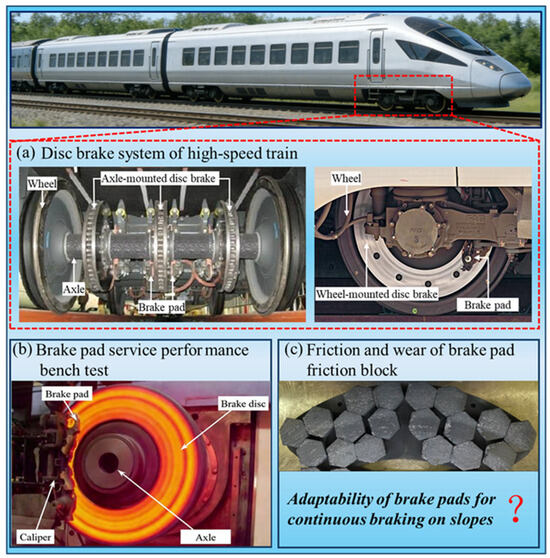
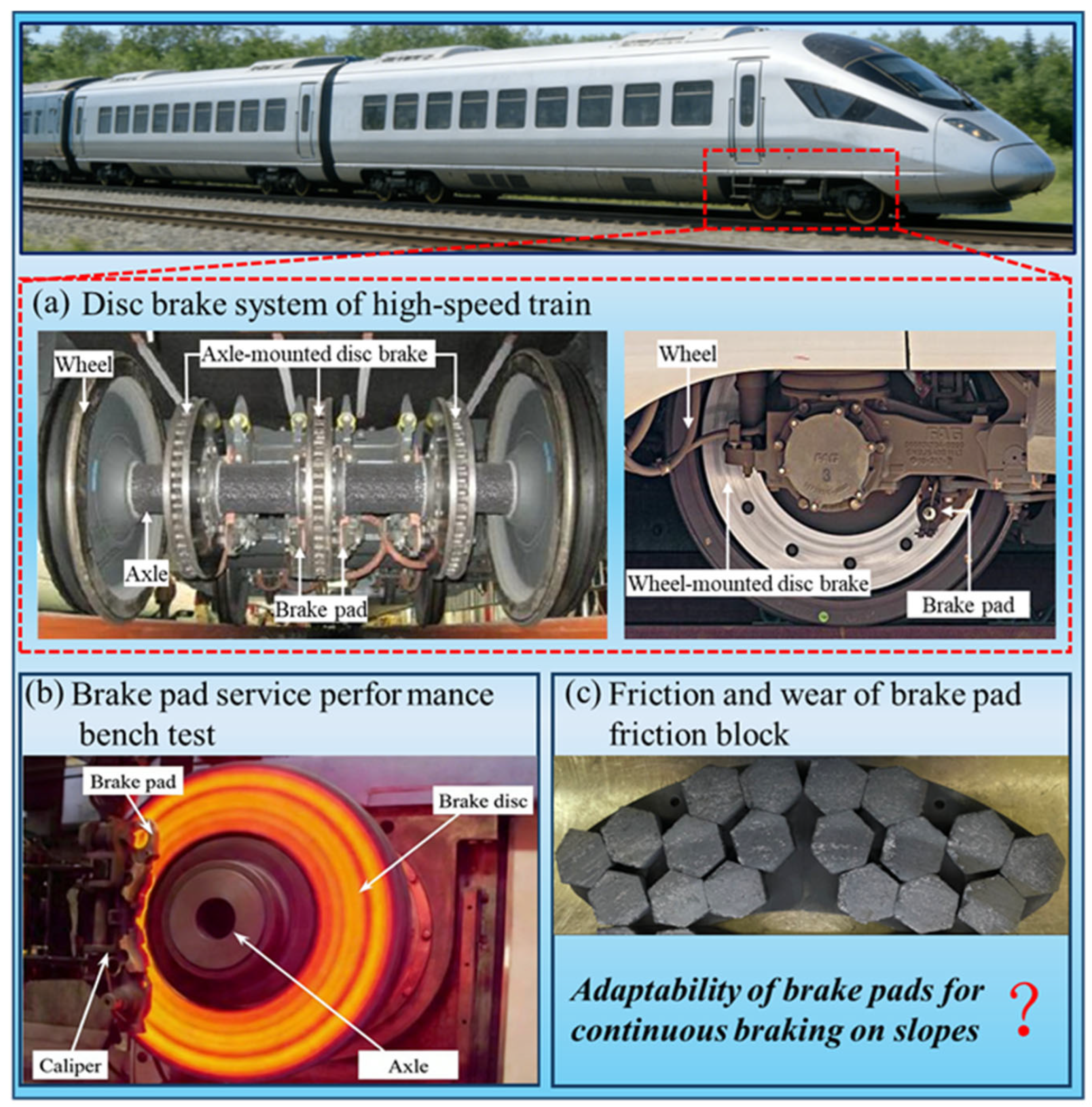
However, with the opening of complex railway lines, braking systems need to face more diverse operating conditions [12], such as mountainous railway lines with long slopes. Slope braking aims to control speed, and compared to stop braking, slope braking is usually implemented at lower speeds and lower braking forces, but the braking time can reach several tens of minutes [13]. Under such long-term continuous braking conditions, the frictional heat and temperature of the friction pair continuously accumulate, resulting in the continuous evolution of the interface friction coefficient, brake pad wear rate, and surface morphology with the braking process, and cause changes in brake pad wear behavior [14,15,16], see Figure 1. At present, the brake pad products for high-speed trains are generally evaluated for their braking performance under high-speed and high braking force conditions [17]. However, given the significant differences in stop braking and slope braking conditions, and the potential for significant differences in brake pad wear behavior, it is urgent to analyze and reveal whether current brake pad products are suitable for continuous slope braking conditions.
Figure 1.
The performance of brake pads during service: (a) Disk brake system of high-speed train, (b) Braking service performance bench test [17], (c) Friction and wear of brake pad.
At present, a relatively systematic research system has been formed for the performance evaluation and wear mechanism analysis of high-speed train brake pads under stop braking conditions, including full-scale brake bench tests, scaled or simplified bench tests, etc. For example, in terms of full-scale testing, Xiao et al. [17] prepared copper-based composite materials and evaluated their braking performance during emergency parking braking using a full-scale test bench, believing that the material showed good potential for application. Zhong et al. [18] compared the service performance of brake pads with rigid connections and flexible connections; the full-scale braking test results indicate that when the speed is higher than 200 km/h, the friction coefficient of brake pads using rigid connections shows more significant attenuation and fluctuation, and their wear rate is significantly higher than that of brake pads with flexible connections. In terms of scaled test bench experiments, Chen et al. [19] studied the braking behavior and wear mechanism of copper-based powder metallurgy brake pads combined with C/C-SiC and 30CrMnSi steel disks under emergency braking conditions. It was found that a dense nanostructured oxide layer of about 600 nm could be formed on the surface of the C/C-SiC disk, thereby improving the friction coefficient and stability, and reducing the wear rate. Deng et al. [20] focused on the connection configuration of brake pads and used a scaled brake test bench to investigate the effect of the floating connection of friction blocks on high-temperature tribological behavior. The results showed that a floating connection helps alleviate the eccentric wear of brake pads. Kasem et al. [21] focused on thermal response in high-energy braking and revealed the correlation between friction interface temperature and deformation through scaled braking tests. The results indicate that the deformation of the brake friction pair is closely related to the level of energy dissipation. From the perspective of geometric structure, Yu et al. [22] demonstrated through scaled bench tests that a reasonable friction block shape can improve the system’s service friction behavior, reduce wear, and enhance braking reliability. Zhang et al. [23] studied the structural evolution of the friction film layer of brake pads under high-temperature conditions using a scaled test bench. It was found that as the temperature increased, the friction film changed from a single-layer structure to a double-layer structure, and the wear mechanism shifted from abrasive wear to adhesive wear. Overall, the research on brake pads under stop braking conditions has covered multiple aspects such as friction materials, connection structures, thermal response, and friction layer evolution, forming a relatively mature experimental method and evaluation approach.
Compared with stop braking, the research on the friction and wear behavior of brake pads under continuous slope braking conditions, especially on long slopes, is still relatively limited. The current work generally uses scaling tests and simulation analysis, focusing on issues such as thermal mechanical response, friction coefficient evolution, and wear mechanism transformation during the slope braking process. In terms of scaling test research, Zhang et al. [24] conducted slope braking tests and diskussed the evolution of friction and wear behavior of friction blocks under different braking durations. The results showed that with the extension of braking time, the friction coefficient tended to stabilize after initial fluctuations, and the wear rate of the friction blocks significantly increased. The wear mechanism gradually shifted from abrasive wear to adhesive wear and oxidative wear. Lu et al. [16] conducted a scaling test on extreme continuous braking conditions and found that the friction coefficient first increased and then decreased with the increase in temperature, and the severe decrease in friction coefficient occurs at temperatures above 400 °C. The wear rate of the friction block showed an upward trend with the increase in temperature. Yin et al. [25] used a small brake test bench to investigate the effect of connection structure on the interfacial frictional behavior, and pointed out that the interfacial frictional behavior is determined by the contact state, interfacial wear, and pressure distribution. The floating connection mode can effectively improve the frictional behavior of the brake system. Ma et al. [26] investigated the sustained braking wear behavior of high-speed train friction pairs under low-temperature environments using a pin-on-disc tribometer and reported significant changes in wear modes with decreasing temperature. Liu et al. [27] simulated slope parking braking under extremely low-temperature conditions using a scaled braking test bench and observed that rapid heat dissipation promoted crack propagation and interfacial debris accumulation, resulting in friction coefficient fluctuations. In terms of simulation analysis, Lu et al. [28] proposed a wear simulation method that combines finite element modeling, Archard theory, and arbitrary Lagrangian-Euler techniques. The model was validated through ramp braking scaling tests, providing methodological support for predicting friction block wear degradation. Chen et al. [29] focused on the matching of thermal expansion and braking parameters, and found through simulation analysis that a reasonable matching of thermal expansion and braking parameters can optimize the wear performance of friction pads. It can be seen that the studies under continuous slope braking conditions, especially on long slopes, have increased in recent years, and provide important references for understanding the frictional behavior and wear mechanism of brake pads during continuous slope braking, but overall, scaling tests and modeling analysis are still the main research methods; the full-scale experimental investigations are still relatively limited. Due to the inability of scaling tests to fully reproduce full-scale test results, especially the high-temperature phenomenon, further analysis is needed on the friction and wear behavior of brake pads with full-scale tests under long slope braking conditions.
In summary, the existing research on brake pads under stop braking conditions is relatively complete. However, the study on the friction and wear behavior of brake pads under slope braking conditions mainly uses scaled bench tests for equivalent analysis, and there is relatively little research on the friction and wear behavior of brake pads under slope braking conditions using full-scale brake test benches. Therefore, this work takes a certain type of high-speed train copper-based powder metallurgy brake pad as the research object, conducts full-scale brake bench tests to analyze the differences in friction and wear behavior of brake pads under stop braking and slope braking, and uses microscopic observation and damage analysis methods to reveal the slope braking adaptability of brake pads.
2. Experimental Description
2.1. Test Bench
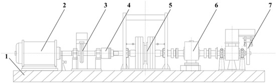
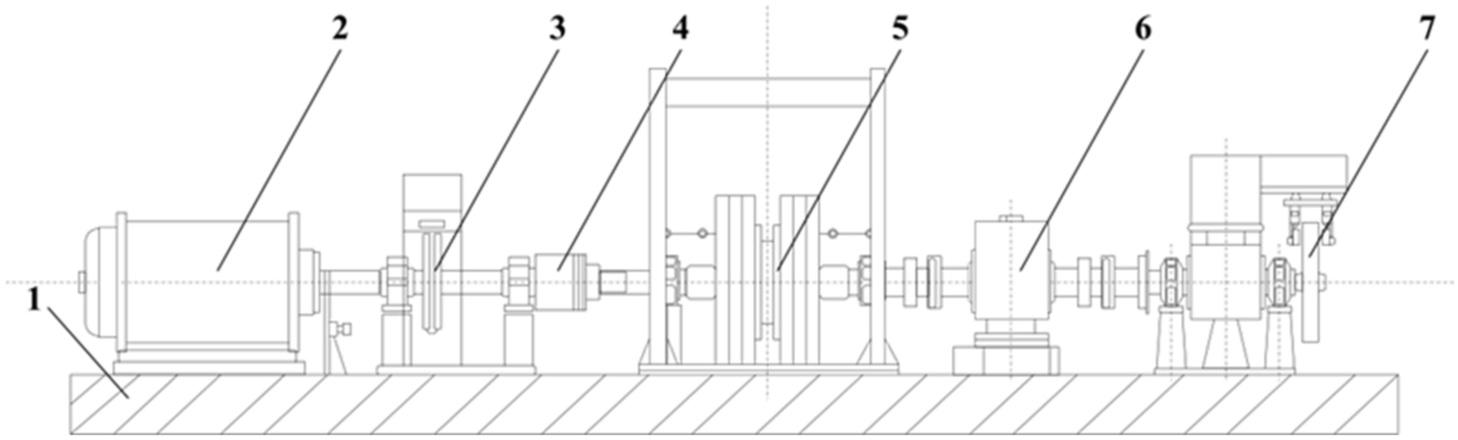
This study used the BD2500/15000 full-scale brake performance test bench manufactured by ZF in Friedrichshafen, Germany to systematically investigate the friction and wear behavior of copper-based powder metallurgy brake pads under slope braking conditions. The schematic diagram of the test bench structure is shown in Figure 2. The test bench adopts a modular design as a whole, mainly including a base that supports and fixes the overall test bench, a driving module that provides power, an emergency braking module that ensures safety, interchangeable flywheel sets, clutches, static friction sensors, brake friction pairs, etc. Among them, the drive module provides controllable speed and power input to the system through the motor and cooperates with interchangeable flywheel sets to simulate different input conditions of equivalent moment of inertia and braking energy. The clutch is set between the drive system and the brake system to achieve rapid engagement and disengagement of power, thereby meeting the needs of switching between different braking conditions. The emergency braking module is used to quickly cut off the power source in case of problems during the test, ensuring the safety of the test. The braking friction pair applies stable and adjustable braking pressure under the action of the control system, achieving simulation of long-term and continuous braking on a slope.
Figure 2.
Diagram of the test bench: (1) base, (2) drive module, (3) emergency braking unit, (4) clutch, (5) interchangeable flywheels, (6) static friction actuator, (7) disk brake system.
In addition to the main structure mentioned above, the experimental system also integrates various auxiliary devices to meet the test requirements of complex service environments. For example, by using a sprinkler system to quantitatively supply water to the contact interface between the brake disk and friction block, it is possible to simulate braking conditions under rain, snow, or humid environmental conditions. The temperature of the brake system is monitored in real time by an infrared temperature measuring device and an embedded thermocouple to obtain the temperature evolution characteristics of the brake pair. The test bench is also equipped with a forced air-cooling device, which controls the heat dissipation conditions during the braking process by adjusting the ventilation configuration and air volume, thus reproducing the actual cooling environment during operation more realistically. The test bench meets the UIC standard [30], and its overall operation action, parameter setting, and data acquisition are completed by a centralized control console. Precise control and synchronous recording of brake pressure, friction coefficient, interface temperature, speed, equivalent mass, water spraying conditions, and cooling conditions can be achieved.
2.2. Test Sample
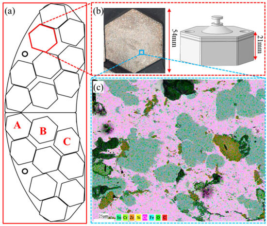
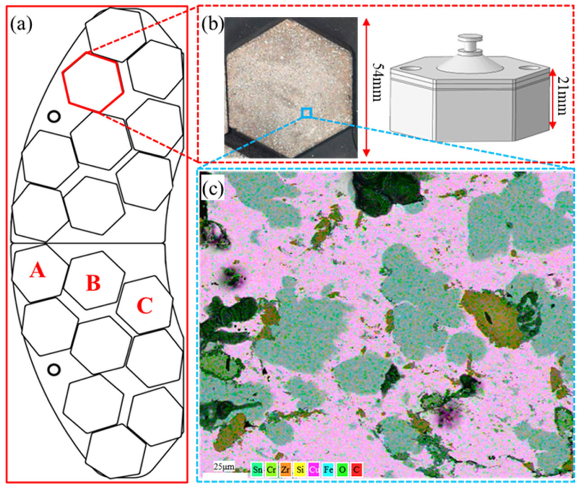
This study conducted braking tests on copper-based powder metallurgy brake pads of a certain in-service high-speed train. By comparing the frictional behavior of brake pads under stop brake and slope brake conditions, the focus is on studying whether the brake pads have good performance and adaptability under continuous slope brake conditions. The analyzed friction pad and its main elemental components are Cu, Fe, C, Si, Cr, Sn, Zr, etc., as shown in Figure 3. The nominal composition of the powder metallurgy brake pad is summarized in Table 1, and the basic physical and mechanical properties of the material are listed in Table 2. Due to the fact that in disk brake systems, brake pads are usually symmetrically distributed on both sides of the brake disk to ensure uniform distribution of braking force and stability during the braking process, this article selects one side of the brake pad for further analysis. In order to facilitate the subsequent analysis of the friction and wear behavior of the brake pad friction block under different friction radius, the sampling locations are marked here, namely A, B, and C, which represent different friction radius. The friction radius of A sample is greater than the average friction radius of the brake pad, the friction radius of B sample is equal to the average friction radius of the brake pad, and the friction radius of C sample is smaller than the average friction radius of the brake pad.
Figure 3.
Brake pad and its element distribution: (a) brake pad, (b) friction block, (c) elemental composition.
Table 1.
Composition of the powder metallurgy brake pad.
Table 2.
Basic physical and mechanical properties of the material.
2.3. Analysis Process
This study designs two braking conditions: stop braking and continuous slope braking. By studying the friction and wear behavior of brake pads, the braking efficiency of copper-based powder metallurgy brake pads under slope braking conditions is evaluated. In the stop braking bench test, a 17-ton axle load was adopted as the test inertia, the maximum braking speed is 380 km/h and the maximum braking force is 36 kN; the braking pressure during the stop braking test is controlled under a constant pressure braking mode. In the slope braking bench test, the equivalent simulated slope is 25‰, the maximum continuous braking speed is 200 km/h, the maximum braking force is 12 kN, and the continuous braking time is 3000 s. The slope braking test is conducted under a constant braking power control mode to simulate the continuous drag braking process during long downhill operation. To account for adverse factors such as tailwind and other extreme operating conditions, a safety amplification factor of 1.1 was applied in the final braking power selection. The braking power during the slope braking is 130 kW. Before the formal test, conduct a sufficient running-in process to ensure that the friction contact area after running in exceeds 85% of the nominal friction surface of the brake pad. In the formal test, record and save various frictional behavior data during the braking process. After the brake test is completed, the overall weight change in the brake pad is tested. Take the friction blocks at positions A, B, and C as the target test samples, test the thickness and mass changes in each friction block, and analyze the wear condition of the brake pad. Measure the overall two-dimensional contour and three-dimensional surface morphology of the friction block surface, and analyze the surface morphology characteristics of the brake pad. Observe the macroscopic and microscopic morphology of the surface and cross-section of the friction block, and analyze the friction and wear state and wear mechanism of the brake pad. Through the multidimensional characterization data above, the frictional behavior and wear mechanism of the brake pads are compared and analyzed, and the adaptability of copper-based powder metallurgy brake pads under slope braking conditions is studied.
3. Analysis of Experimental Results
3.1. Overall Condition of the Brake Pad
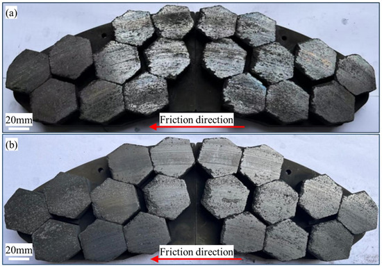
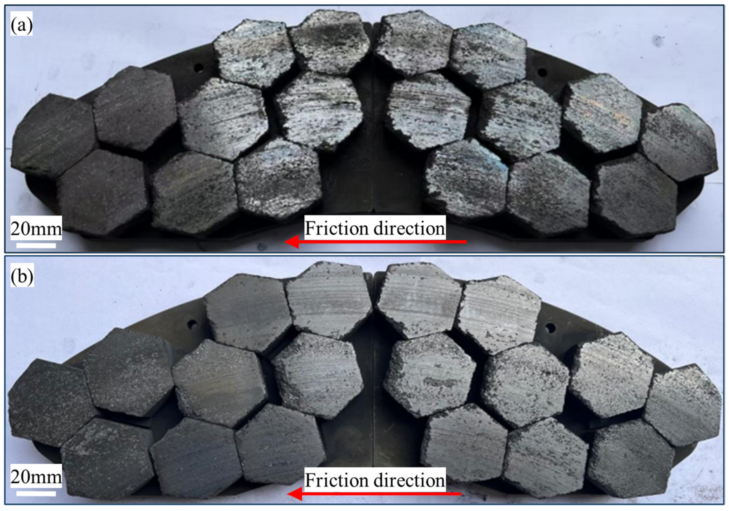
After completing the experiment, take photos of the brake pad and record its overall surface condition, as shown in Figure 4. Figure 4a shows the brake pad after undergoing high-speed and high braking force stop braking tests. There are obvious scratches and exfoliation on the surface of the friction block and severe damage at the edges. The overall surface is relatively rough. There are darker colored areas on the surface of some friction blocks, which result from the debris compacted on the surface of the friction blocks during the braking process. Figure 4b shows the brake pad after undergoing a slope braking test. Although some friction blocks also have severe damage at the edges, the surface of the brake pad friction blocks is relatively flat, and the scratches and exfoliation on the surface are relatively light compared to the stop braking. From the overall surface state, there are significant differences in the surface of the brake pads under the two operating conditions. Various characterization analyses will be carried out in the following to further study their friction and wear behavior.
Figure 4.
Overall surface condition of the brake pads after the test: (a) stop braking, (b) slope braking.
3.2. Temperature and Friction Coefficient
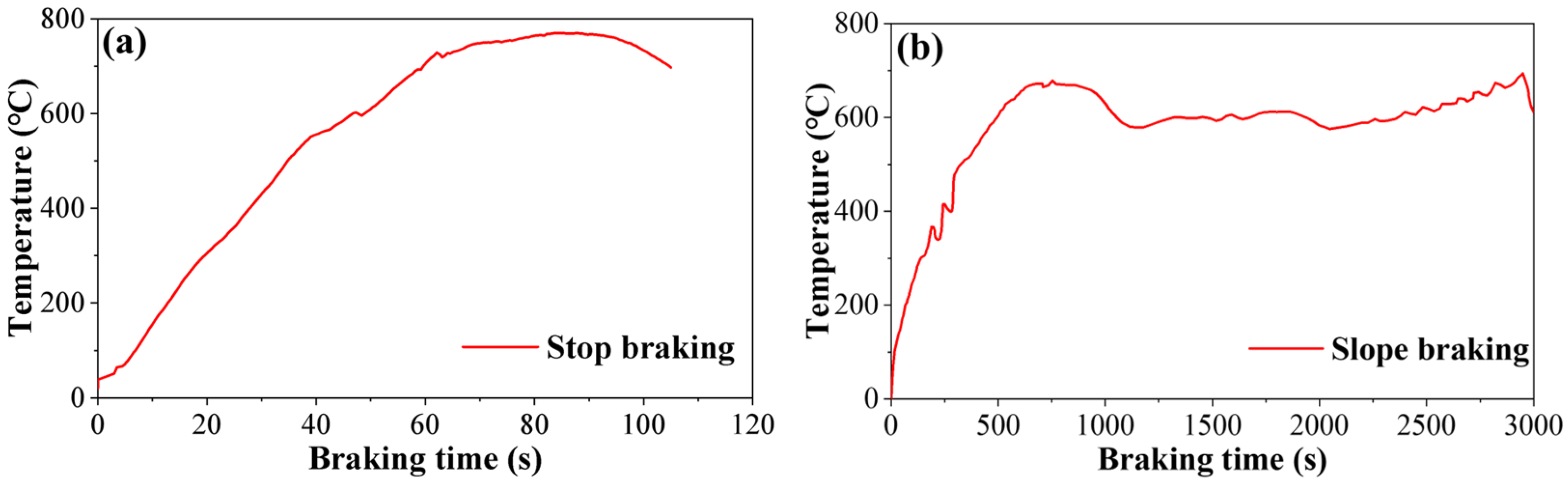
The variations in braking interface temperature (represented by the temperature of the brake disk at the average friction radius) are presented in Figure 5, where Figure 5a represents the temperature variation in the stop braking condition and Figure 5b represents the results in the slope braking condition. During the stop braking, the temperature reaches a peak temperature of approximately 750 °C. Subsequently, as the train speed gradually decreases, the braking power continuously declines, resulting in reduced thermal input at the interface and a gradual decrease in temperature. Overall, the temperature evolution during stop braking is characterized by a high peak temperature and a relatively short thermal duration. In contrast, the temperature evolution during slope braking exhibits a significantly different trend. The temperature gradually increases with time and reaches a peak temperature of approximately 680 °C. After that, the temperature remains stable and fluctuates within a certain range. Overall, the temperature evolution during slope braking is characterized by a relatively slow heating process, long duration, and a stable interface temperature maintained for an extended period, indicating that the friction interface gradually reaches a relatively stable thermal state during slope braking.
Figure 5.
Temperature variation during the braking process: (a) stop braking, (b) slope braking.
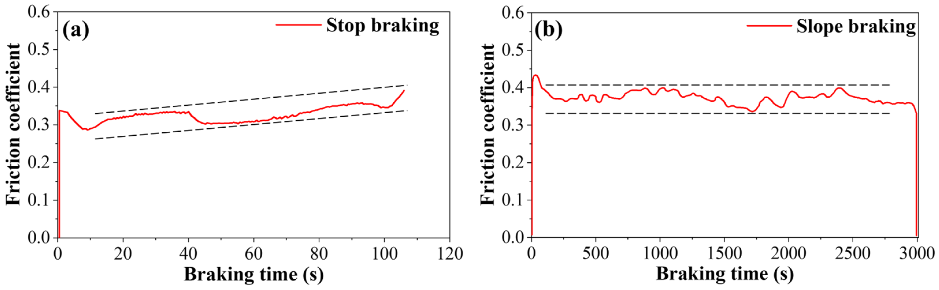
Figure 6 shows the evolution of the friction coefficient under the two braking conditions, where Figure 6a corresponds to stop braking, and Figure 6b corresponds to slope braking. The results show that the friction coefficients in both cases remain within a reasonable operating range, which indicates that the powder metallurgy brake pad maintains relatively stable friction performance under both braking conditions. The average friction coefficient under stop braking is approximately 0.326, while that under slope braking is approximately 0.367. To stop braking, the friction coefficient exhibits an overall increasing trend during the braking process. The maximum value appears near the end of braking. This behavior is mainly associated with the gradual reduction in braking energy input and the reduction in interface temperature at the later stage of braking. For slope braking, the friction coefficient remains relatively stable throughout the braking process. Although local fluctuations can be observed, the overall behavior remains in a dynamically stable state.
Figure 6.
Friction coefficient variation during the braking process: (a) stop braking, (b) slope braking.
3.3. Braking Power
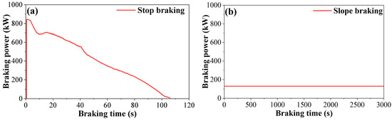
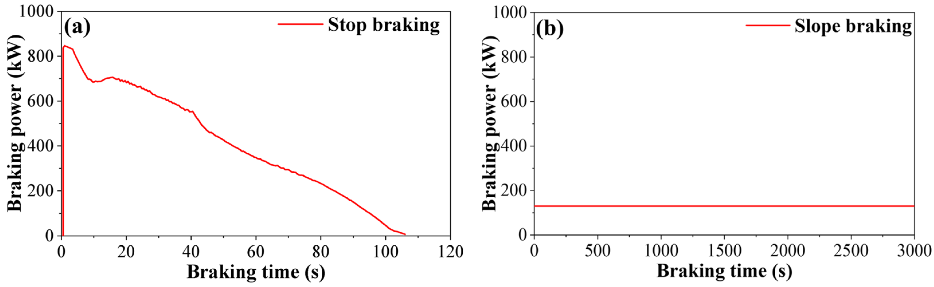
The braking power variation is presented in Figure 7. For the stop braking condition, it can be seen that the initial peak instantaneous braking power under stop braking is approximately 822 kW. As the braking process proceeds, the train speed gradually decreases, leading to a reduction in sliding velocity at the friction interface, and the instantaneous braking power correspondingly decreases. In contrast, the slope braking is conducted under a constant power control mode, with the braking power maintained at approximately 130 kW for a prolonged period. Although the instantaneous power is significantly lower than that of stop braking, the long braking duration leads to continuous heat input at the friction interface. Consequently, the slope braking exhibits the characteristic of lower but sustained power input. The significant difference in the time history of braking power between the two conditions indicates that stop braking is dominated by short-duration high-power thermal loading, whereas slope braking corresponds to long-duration low-power thermal input.
Figure 7.
Braking power variation during the braking process: (a) stop braking, (b) slope braking.
3.4. Wear Characteristics
The wear amount of brake pads is an important indicator for evaluating the service performance. Due to the shape deviation of the friction blocks at different positions, the wear percentage can better reflect the wear of the friction blocks at different positions. The wear of the brake pad is shown in Table 3. As shown in the table, notable mass loss occurred in the friction pads under both braking conditions, but there were significant differences in wear levels. The overall wear of brake pads under stop braking conditions is significantly higher than that under slope braking conditions. Under stop braking conditions, the wear percentages of friction blocks A, B, and C are 26.90%, 21.81%, and 16.83%, respectively, with an average of 21.85%. The wear percentages of friction blocks A, B, and C under slope braking conditions are 8.26%, 7.66%, and 7.20%, respectively, with an average of 7.71%. It should be clarified that the absolute mass loss is strongly influenced by the friction distance, which is different under the two braking conditions. But the relative wear differences among friction blocks at different positions can be a certain indicator for the uneven wear of the brake pad. Further comparison of the wear differences at different positions reveals that the degree of wear under both operating conditions follows a pattern of A (outer) > B (middle) > C (inner), indicating significant uneven wear of the friction blocks at different positions. However, under slope braking conditions, the uneven wear of the friction blocks at different friction radius is relatively light, and the overall wear of the brake pads is relatively uniform.
Table 3.
The wear of the friction blocks at positions A, B, and C.
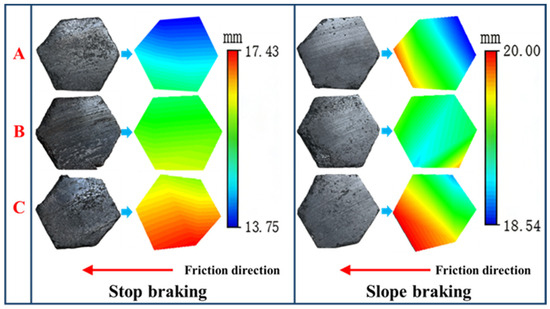
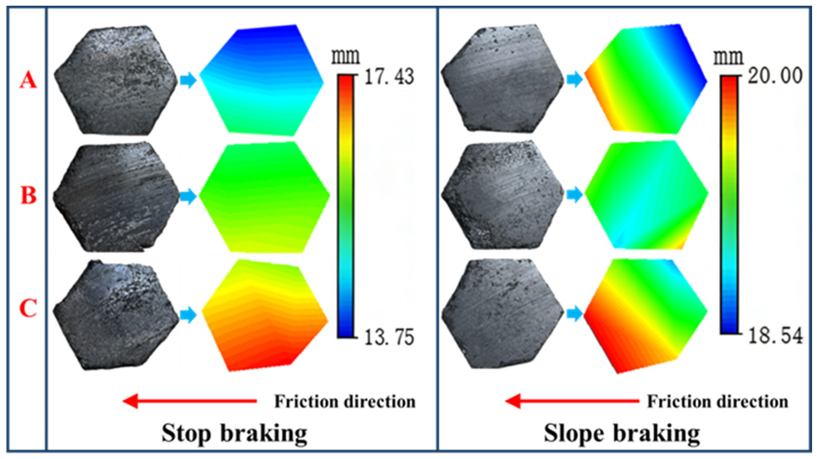
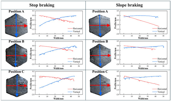
After obtaining the overall wear mass of the brake pad friction blocks at different positions, further measurement of the remaining thickness of the friction blocks is carried out to obtain the eccentric wear characteristics of the friction blocks at different positions. When measuring the remaining thickness, ensure that the friction block is placed at the same angle as its installation position on the steel backplate. The remaining thickness is measured at six vertices of the friction block, and each vertex is measured three times to reduce measurement uncertainty. If chipping or local breakage occurs at the vertex, the measurement position is shifted to the nearest contact platform adjacent to that vertex, and the height of this contact platform is taken as the remaining thickness for that location. The thickness cloud map is displayed in Figure 8. It can be seen that apart from uneven wear of friction blocks at different positions, i.e., the wear of the friction block increases along the friction radius. For a single friction block, there is eccentric wear along the radius and friction direction under stop braking conditions, while the eccentric wear along the radius direction is weaker than along the friction direction under slope braking conditions. The differences in eccentric wear characteristics between the two braking conditions are closely related to the thermo-mechanical loading history. Under the stop braking condition, the heat input is highly concentrated, and the temperature rises rapidly. The outer side experiences a longer sliding distance; the difference between the radial temperature field and the thermal stress field of the brake pad is amplified, which dominates the difference in radial eccentric wear of the brake pad. In contrast, the slope braking has a longer duration and more stable heat input, resulting in a more uniform temperature field, which weakens the temperature difference and thermal stress difference between the inside and outside of the brake pads. The eccentric wear is mainly along the friction direction.
Figure 8.
Thickness distribution of friction blocks.
To further establish a quantitative energetic baseline between the two braking conditions, the energy input and the corresponding brake pad wear characteristics are summarized in Table 4. In terms of total dissipated energy, the two braking conditions show comparable values, with 760 MJ for stop braking and 780 MJ for slope braking, indicating a similar overall level of energy input. However, a significant difference exists in the average specific power density at the friction interface. The average specific power density under stop braking reaches 1.117 kW/cm2, which is substantially higher than that under slope braking at 0.325 kW/cm2. Under stop braking, the high average specific power density leads to a rapid and concentrated energy input within a short duration, resulting in a sharp temperature rise at the interface. Under such conditions, the interface stability is more easily disrupted, and the material response is characterized by intense material removal, ultimately leading to a higher wear rate of 0.38 cm3/MJ. In contrast, slope braking is characterized by a lower average specific power density combined with a much longer duration. The energy is introduced in a gentler manner, allowing the friction interface to maintain a relatively stable state, resulting in a mild material removal process. Consequently, the wear rate is 0.14 cm3/MJ in the slope braking condition. Further analysis of surface morphology and damage characteristics is presented in the following section to clarify the underlying mechanisms.
Table 4.
Comparison of brake pad wear characteristics under different braking conditions.
3.5. Two-Dimensional Contour Features
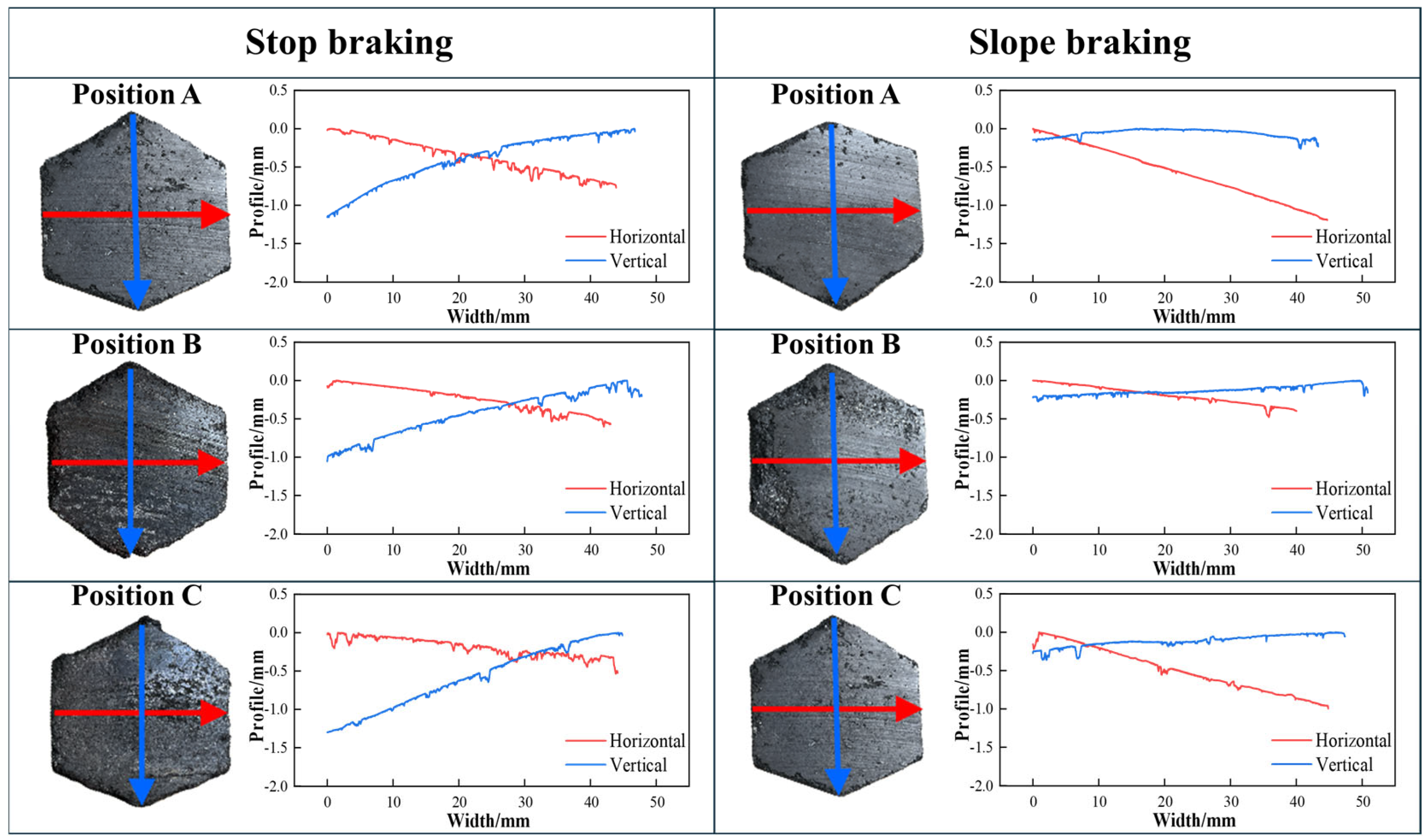
To further analyze the wear and damage of the brake pad surface, the two-dimensional profile of the brake pad friction block surface is measured, as shown in Figure 9, which displays the surface profile curves of the friction block along the friction direction (Red line) and the radial direction (Blue line). Comparing the overall trend of the two-dimensional contour, it can be found that the contour of the friction block has different characteristics under different braking conditions. After experiencing stop braking, although the friction block has eccentric wear in both the radial and friction directions, the degree of eccentric wear in the radial direction is higher. After slope braking, there is mainly eccentric wear along the friction direction, and the degree of wear along the radius direction is relatively uniform. In addition, from the fluctuation trend of the contour curve, it can be seen that the contour curve of stop braking fluctuates more frequently, with more local short wavelength fluctuation, which usually corresponds to more damaged areas on the surface. In contrast, the contour curve of slope braking is generally smoother, with lower fluctuation frequency and amplitude compared to stop braking, indicating that brake pads tend to wear out gradually, and the surface morphology evolution is more continuous under slope braking conditions.
Figure 9.
2D profile of friction blocks.
3.6. Surface Morphology
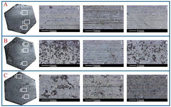
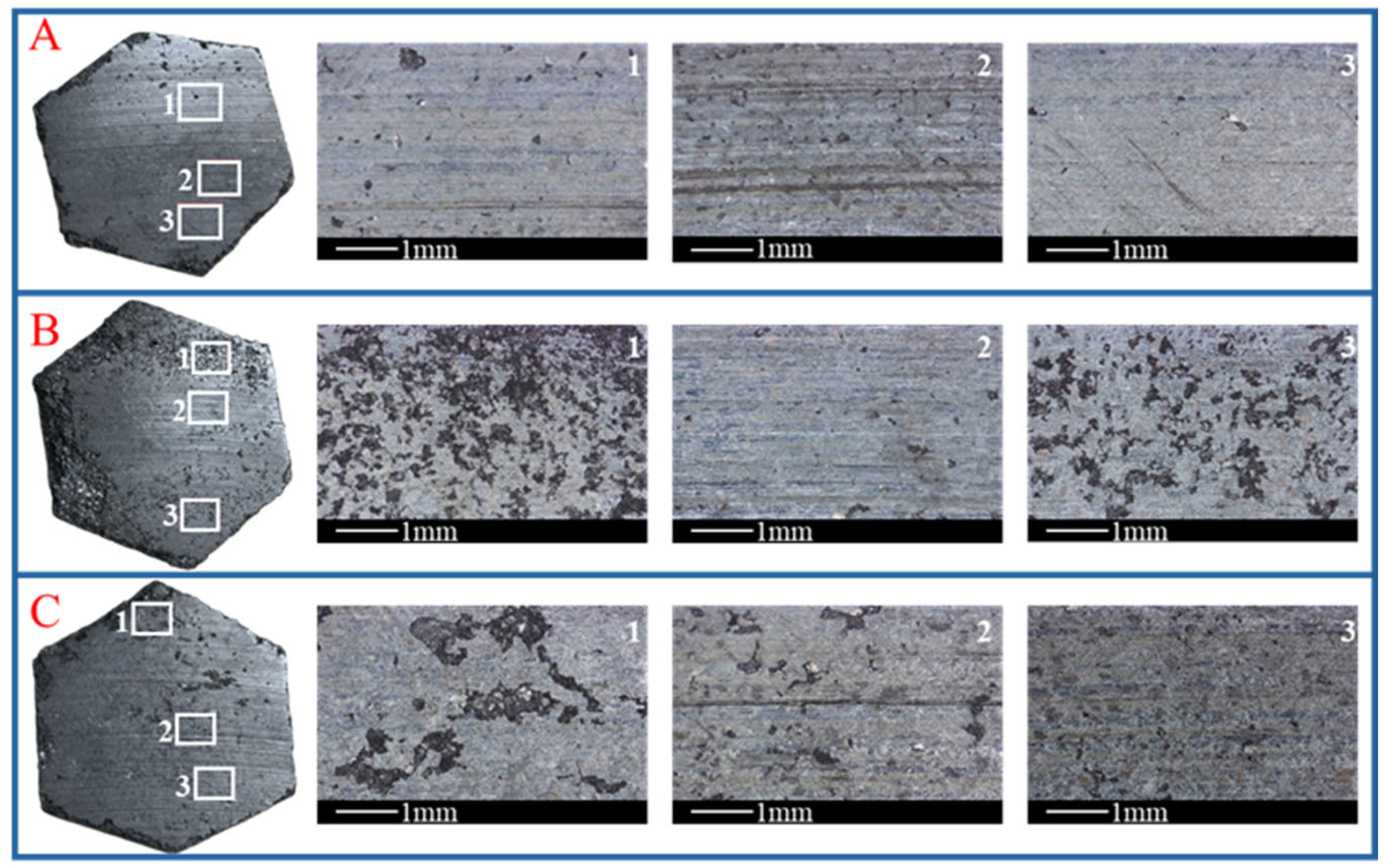
In order to further study the surface damage of the brake pad, the macroscopic morphology of the friction block surface is observed, as shown in Figure 10 and Figure 11, which are the surface morphology of the friction block under stop braking and slope braking conditions, respectively. Under stop braking conditions, the surface of the friction block is generally rough, and the contact platform presents a fragmented and pitted appearance. The surface is mainly characterized by a large and dense amount of exfoliation, which has become interconnected and fused into larger spalling. At the same time, it can be seen that there are obvious scratches distributed along the friction direction, with a relatively dense number and large scale. This is because the brake pads are severely worn under stop braking conditions, and the debris remains at the contact interface as a third body participating in surface plowing. Under slope braking conditions, the overall surface of the friction block is relatively flat, and the contact platform is relatively smooth. Compared to the stop braking, the friction block surface has a small amount of exfoliation, with a smaller size and sparse distribution, and the damage is not connected. At the same time, the surface scratches are relatively minor.
Figure 10.
Surface morphology of the friction block after stop braking.
Figure 11.
Surface morphology of the friction block after slope braking.
3.7. Characteristics of Surface Damage
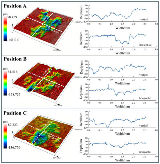
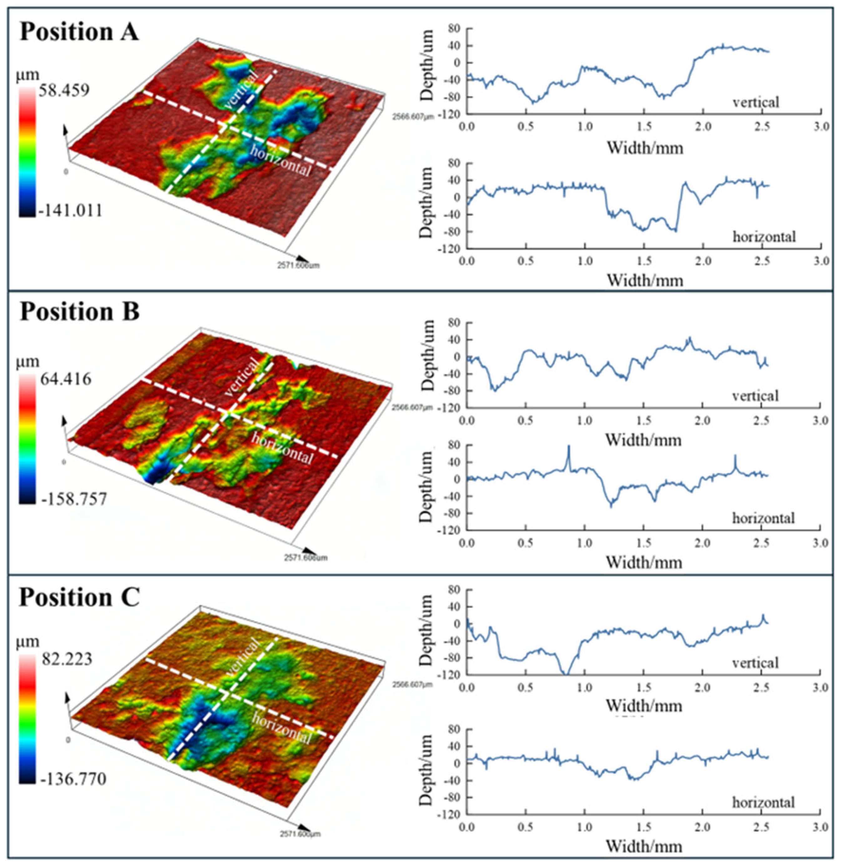
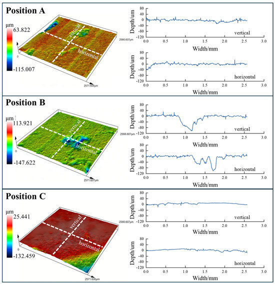
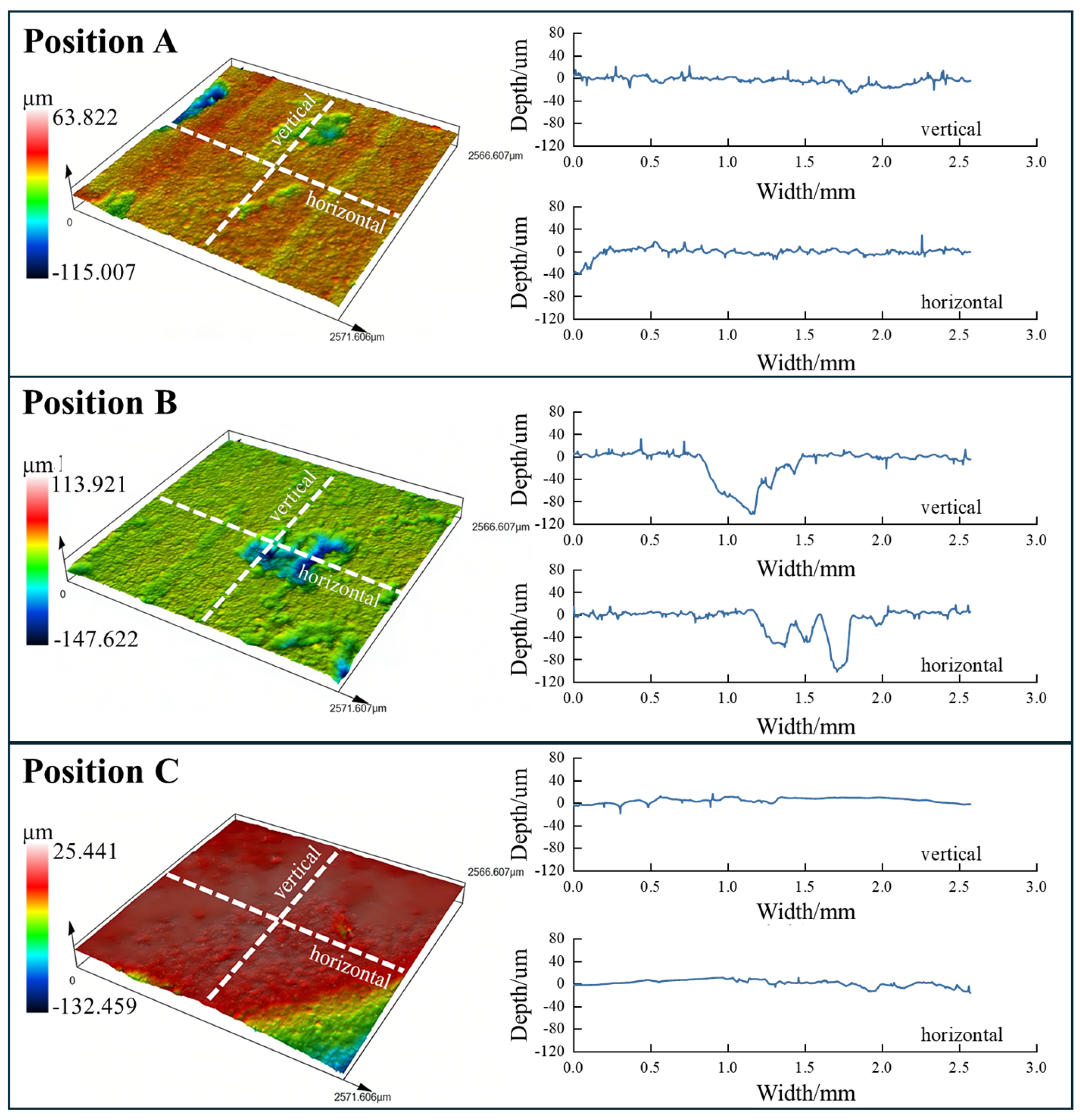
The typical surface damage to friction blocks is characterized, as seen in Figure 12 and Figure 13, which are the characteristics of brake pad surface damage under stop braking and slope braking, respectively. The color image on the left side of the figure shows the three-dimensional morphology of local damage features, with the red and yellow areas being relatively high in height, generally corresponding to contact platforms and residual protrusions; the blue and green areas being relatively low in height, generally corresponding to exfoliation and scratches. The two lines on the right side indicate the profile of the typical damaged area along different directions. It can be noticed that the scale and depth of surface damage on the friction block under stop braking conditions are larger, and the damage has interconnected characteristics. At the same time, there are many fluctuations along different directions, and the overall contact platform is fragmented and has poor continuity. For friction blocks under slope braking conditions, the surface damage size is small, and the amplitude and frequency of profile fluctuations are generally lower than those of the stop braking. The friction surface is flatter, and the contact platform is more continuous.
Figure 12.
3D surface damage characteristics under stop braking.
Figure 13.
3D surface damage characteristics under slope braking.
3.8. Wear Behavior of Brake Pad Friction Block
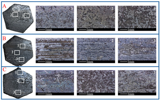
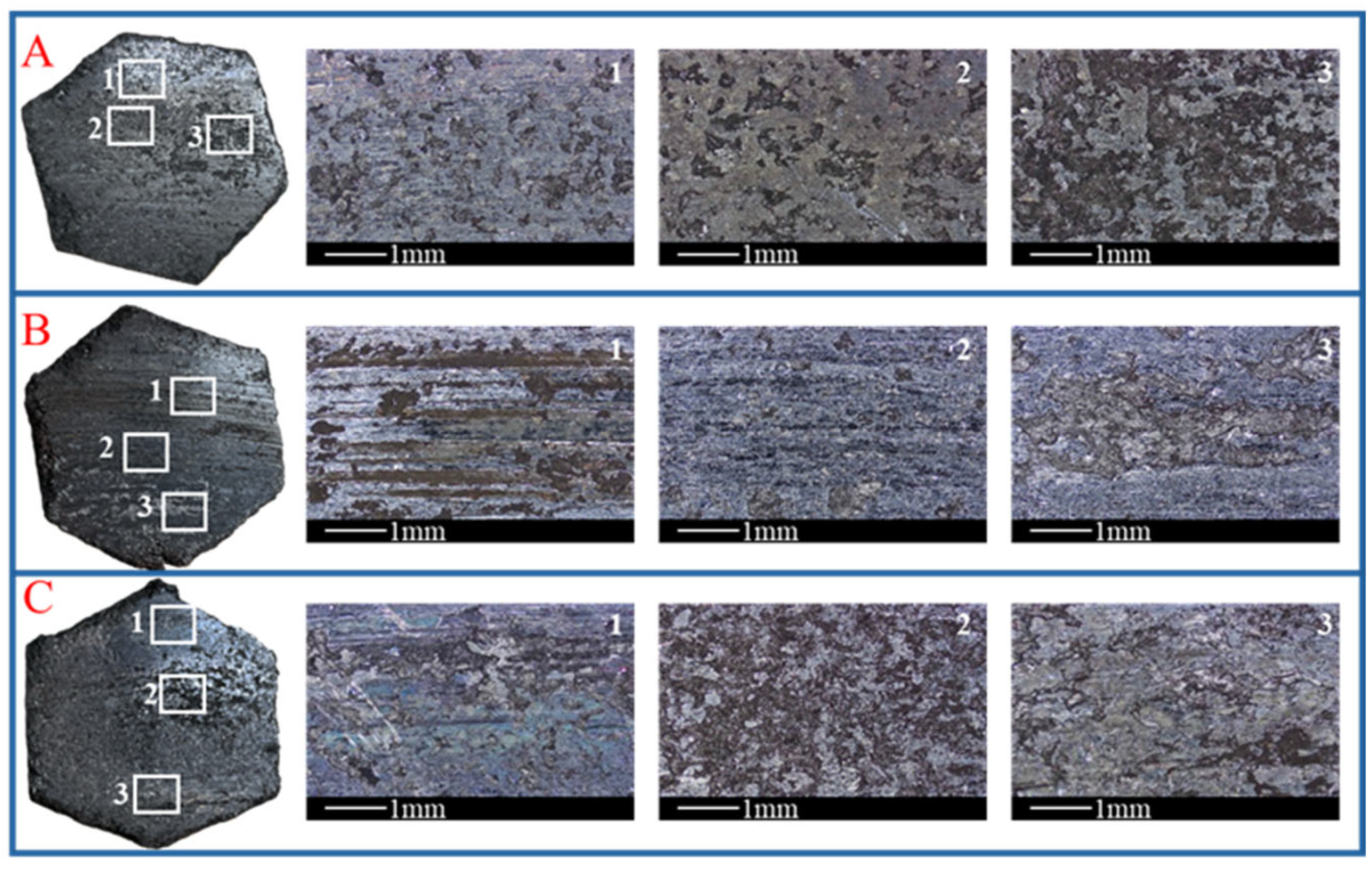
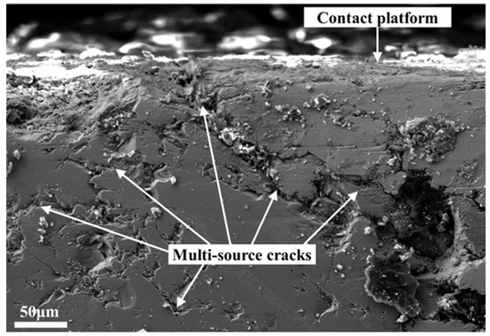
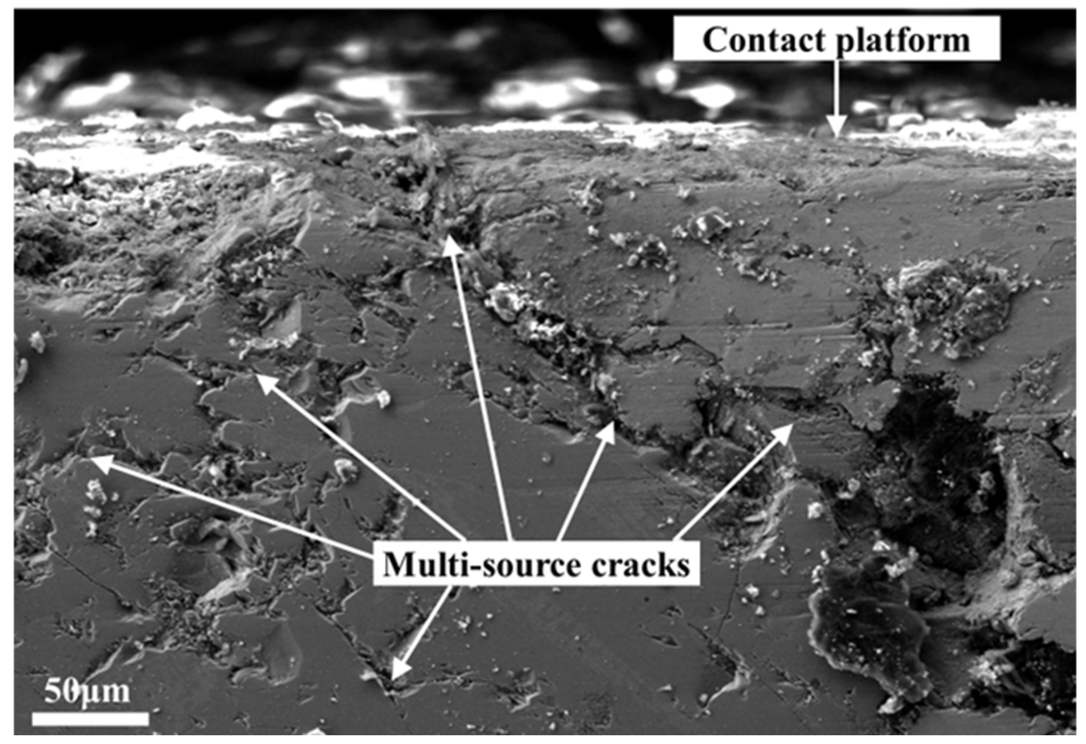
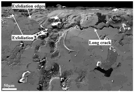
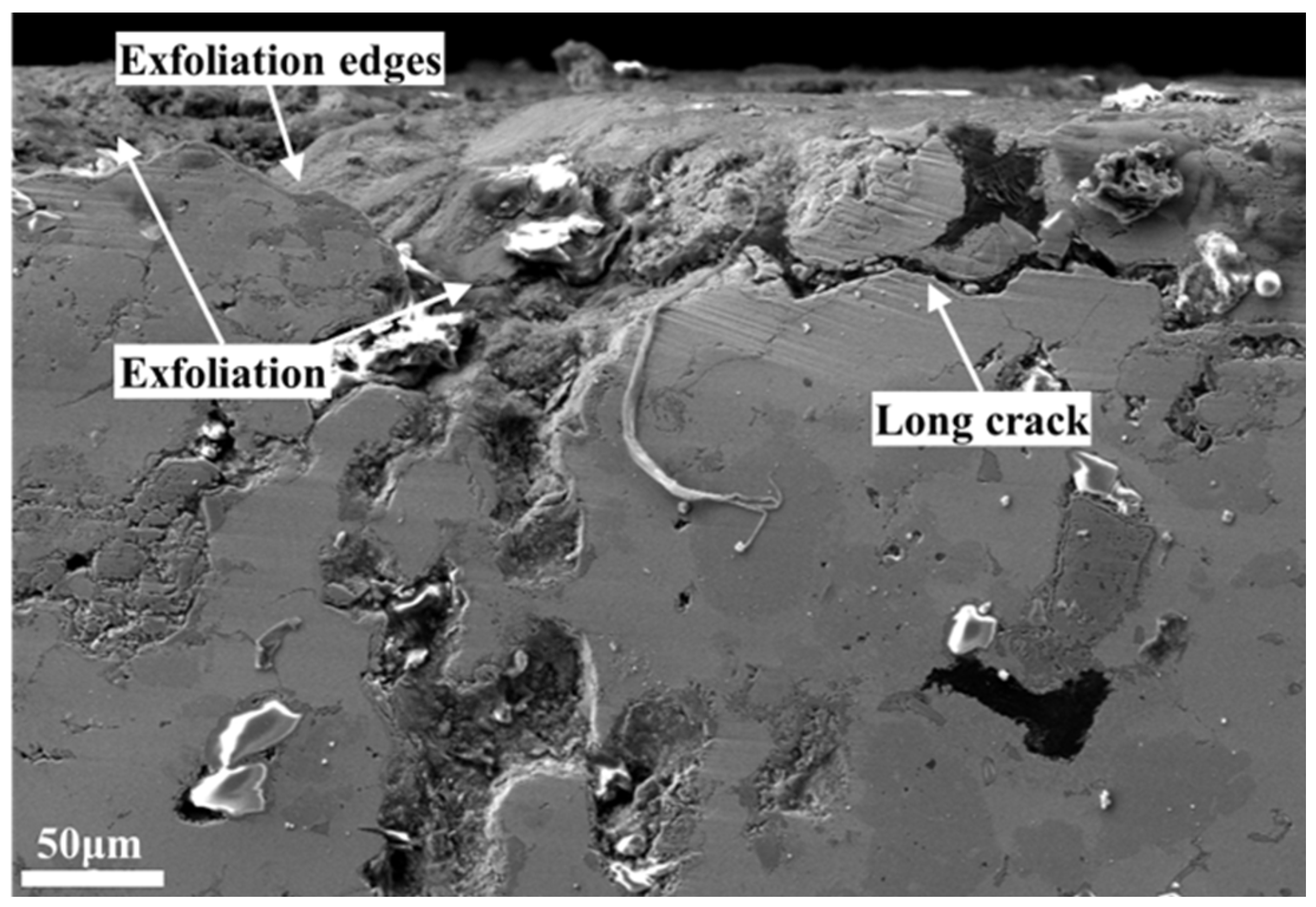
Given that brake pads have significantly different surface morphologies and damage characteristics under different braking conditions, further analysis is needed to identify the reasons for the different wear behaviors of brake pads. Due to the fact that the surface of the brake pad can be roughly divided into the damaged area and the contact platform area, the microstructure observation of the damaged area and the contact platform area is conducted here. Figure 14 and Figure 15 show the microscopic characteristics of the friction block under stop braking conditions. In the contact platform area, as shown in Figure 14, multiple short cracks appear on the friction block, with relatively scattered distribution and obvious multi-source crack characteristics. Some cracks are interconnected and staggered during the propagation process, which can easily induce block shaped or irregular exfoliation. The surface contact platform is relatively rough and has poor continuity. Local contact surface areas are cut by cracks or exfoliation boundaries, indicating that the stable contact state of the friction interface is difficult to maintain for a long time under stop braking conditions. In the surface damage area, as shown in Figure 15, it can be seen that the damage morphology of the friction block is mainly block shaped exfoliation. Clear fracture edges and rough sections can be seen inside the damaged area, indicating that the material has undergone strong stress concentration and brittle failure characteristics in the local area. At the same time, cracks originate from the damage area and continue to develop into long cracks.
Figure 14.
Microscopic characteristics of the contact platform area under stop braking.
Figure 15.
Microscopic characteristics of the damage area under stop braking.
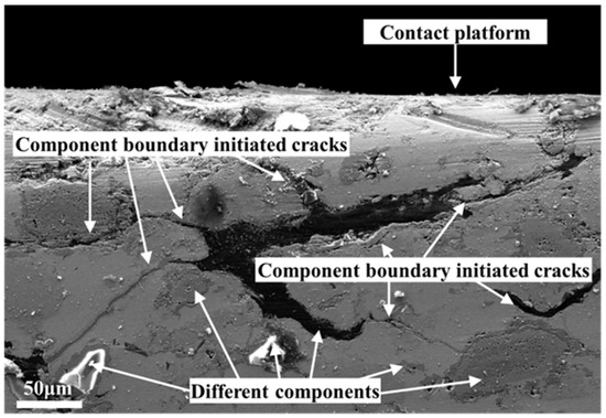
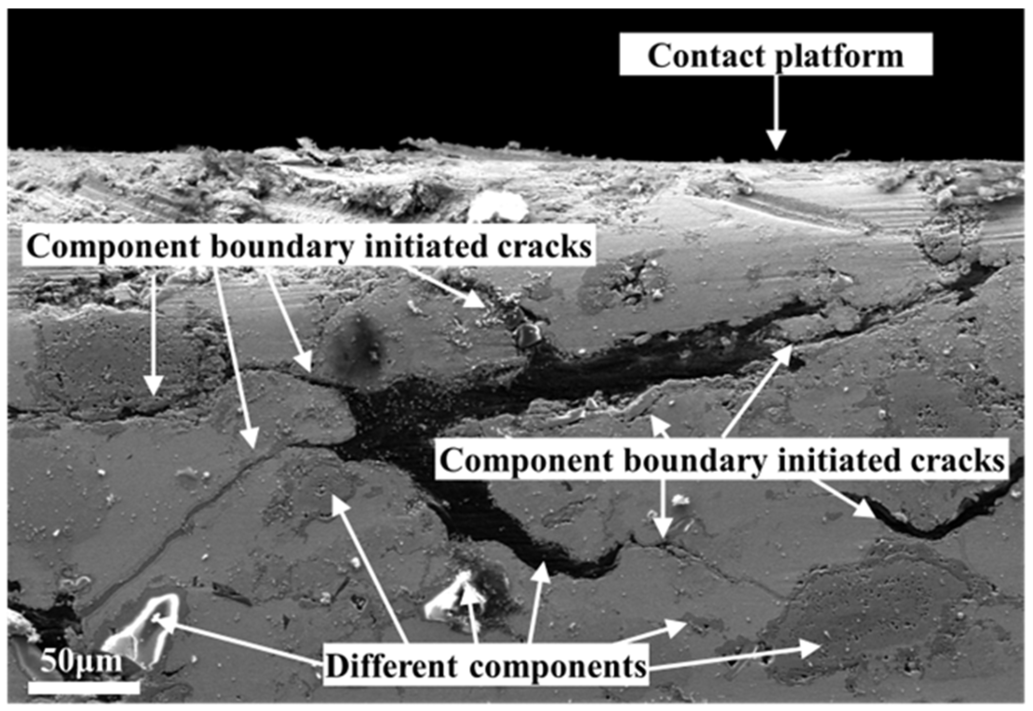
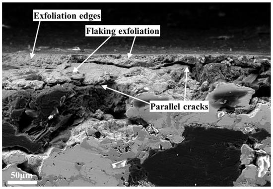
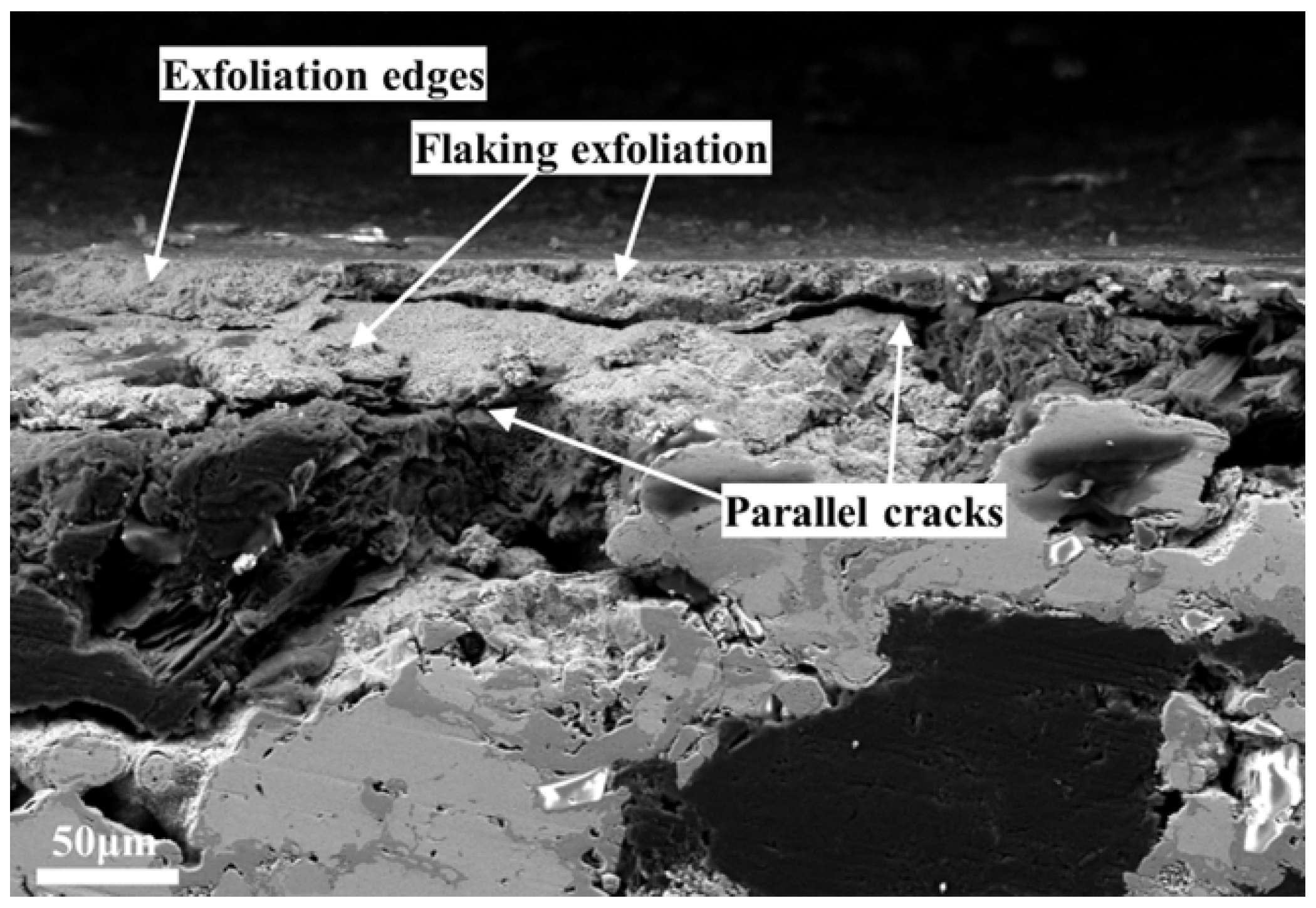
Figure 16 and Figure 17 show the microscopic characteristics of the friction block under slope braking conditions. Compared with those under the stop braking condition, the friction block microstructures show significant differences under slope braking conditions. In the contact platform area, as shown in Figure 16, it can be seen that the number of cracks in the friction block is less after slope braking, but the crack length is longer. The cracks mostly originate along the boundaries of the components, as shown in the figure, the crack that extends from the graphite component to the matrix, presenting a long and continuous shape with a clear propagation path. The contact platform area of the friction block is flat and has good overall continuity. In the damage area, as shown in Figure 17, the surface of the friction block under slope braking presents a flake exfoliation form, and the damage boundary is clear. Meanwhile, the crack development path is approximately parallel to the friction interface, leading to local friction interface failure and delamination under repeated friction. This layered damage characteristic indicates that friction damage during slope braking tends to accumulate gradually along the weakly bonded areas of the friction interface, rather than experiencing severe wear in a short period of time.
Figure 16.
Microscopic characteristics of the contact platform area under slope braking.
Figure 17.
Microscopic characteristics of the damage area under slope braking.
4. Slope Braking Adaptability
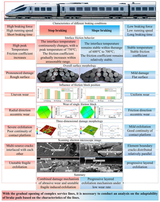
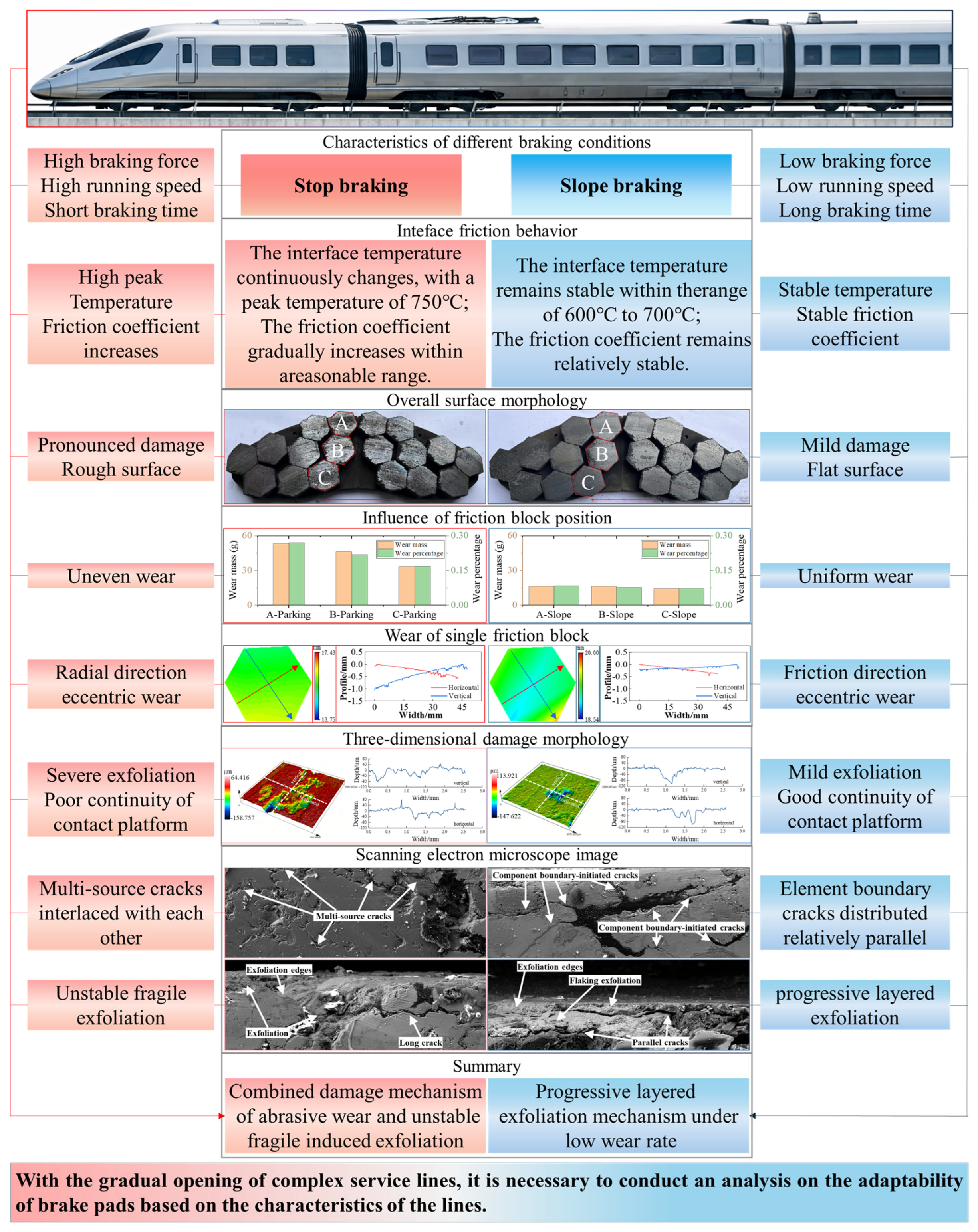
Through the above analysis, it can be found that brake pads under different braking conditions not only have differences in wear degree and surface morphology but also have essential differences in their damage formation mechanism and evolution mode, as shown in Figure 18. Although the total dissipated energy under the two braking conditions is comparable, the average specific power density exhibits significant differences, which affect the thermo-mechanical response at the braking interface significantly. Therefore, it is necessary to conduct a slope braking adaptability evaluation for existing brake pad products. For stop braking, it has the characteristics of a large braking force, high braking speed, and short action time. The peak friction power during stop braking reaches about 822 kW, corresponding to an average specific power density of 1.117 kW/cm2, indicating the brake pads bear concentrated input of high-level mechanical and thermal loads in a short period of time. At the macro level, the wear of the brake pads is severe and uneven, and the degree of eccentric wear of the friction blocks in the radial direction is higher. The surface damage scale is larger and denser, the surface contour fluctuates significantly, and the continuity of the contact platform is poor. At the micro level, the cracks in the friction block are short and scattered. Under the stop braking condition, a more pronounced temperature gradient has occurred inside the pad matrix. The resulting thermal stress is relatively high and non-uniformly distributed, so multiple weak sites reach the cracking condition simultaneously, and cracks initiate in a dispersed, multi-source manner. Under the impact of high-speed, high braking force, and severe thermal load, multiple sources of cracks are interconnected and exhibit brittle failure characteristics, inducing block like or irregular exfoliation to repeatedly occur, causing the contact platform to be repeatedly cut and leading to a decrease in interface stability. Due to the constantly changing interface temperature, it has not reached a stable state and further leads to continuous changes in the friction coefficient. Under stop braking conditions, the brake pads exhibit a composite wear mechanism of abrasive wear and unstable brittle failure induced exfoliation.
Figure 18.
Friction behavior of brake pads under different service conditions.
In contrast, slope braking has lower braking force and braking speed, longer braking time, and relatively stable heat input with constant braking power of 130 kW; the corresponding average specific power density at the friction interface is approximately 0.325 kW/cm2, indicating a moderate but continuous energy input over a long duration. These characteristics result in the wear of friction blocks at different positions being more uniform. The eccentric wear of friction blocks is mainly along the friction direction. The overall surface of the friction block is flat, and the continuity of the contact platform is good. Only local areas show surface damage, and the contact state is relatively stable. At the micro level, a small number of cracks initiate along the component interface. The mismatch in thermal expansion and mechanical response among different components becomes the primary driving factor for crack initiation. The crack propagation path is approximately parallel to the friction surface, gradually accumulating under the repeated action of frictional force, and ultimately leading to flaking exfoliation or delamination damage. Under slope braking conditions, due to the stable and continuous braking power, the temperature and friction coefficient of the braking interface fluctuate within a stable range, the brake pads are prone to forming a stable friction film and a third body layer, exhibiting a progressive delamination damage mechanism at low wear rates.
In summary, due to significant differences in the time history of braking load and thermal load under different braking conditions, brake pads exhibit different friction and wear behaviors. Therefore, with the gradual opening of complex service lines, it is necessary to conduct adaptive analysis of brake pads based on the characteristics of the service lines.
5. Conclusions
This article focuses on the wear of high-speed train brake pads. Through full-scale brake bench tests, the slope braking adaptability of current brake pad products is studied from the perspectives of wear amount, surface profile, damage morphology, and wear behavior. By comparing and analyzing the service performance of brake pads under stop braking and slope braking conditions, there are significant differences in the friction and wear behavior and damage evolution characteristics of brake pads under different braking conditions. The main conclusions are as follows.
- (a)
- The brake pads under stop braking conditions exhibit significant overall uneven wear, while the overall uneven wear of the brake pads is lower under slope braking conditions. For a single friction block, there is eccentric wear along the friction and radius direction under stop braking conditions, while the eccentric wear along the radius direction is weaker than along the friction direction under slope braking conditions.
- (b)
- Under stop braking conditions, the surface contour of the friction block fluctuates more significantly, with a large number and larger size of scratches and exfoliation. The surface damage is connected, leading to a rough friction surface and poor continuity of the contact platform. In contrast, after slope braking, the surface contour of the friction block fluctuates relatively gently, with fewer and milder surface damage, as well as a smoother contact platform.
- (c)
- Under the impact of high speed, high braking force, and severe thermal load, cracks in the brake pad originate from multiple sources and propagate alternately, resulting in repeated exfoliation and making it difficult to maintain a stable friction film and third body layer at the friction interface. The brake pad exhibits a composite wear mechanism of abrasive wear and unstable brittle failure induced exfoliation. Under the action of low speed, low braking force, and long-term stable thermal load, the cracks in the brake pad mainly originate along the interface of the components and propagate parallel to the friction surface direction. The brake pad exhibits a progressive accumulated delamination and flaking exfoliation at low wear rates. The results indicate that although the friction interface of the brake pad is relatively stable under slope braking conditions, further attention needs to be paid to the cumulative delamination wear of the brake pad under long-term braking action.
Funding
This research received no external funding.
Data Availability Statement
The original contributions presented in the study are included in the article, further inquiries can be directed to the corresponding author.
Conflicts of Interest
Author Xueqian Geng was employed by the company Beijing Zongheng Electro-Mechanical Technology Development Co., Ltd. The company was not involved in the study design, collection, analysis, interpretation of data, the writing of this article or the decision to submit it for publication.
References
- Lu, C.; Shen, J.; Fu, Q.; Mo, J. Research on Radial Crack Propagation of Railway Brake Disc under Emergency Braking Conditions. Eng. Fail. Anal. 2023, 143, 106877. [Google Scholar] [CrossRef] [Scilit]
- Wang, Z.; Han, J.; Liu, X.; Li, Z.; Yang, Z.; Chen, E. Temperature Evolution of the Train Brake Disc during High-Speed Braking. Adv. Mech. Eng. 2019, 11, 1687814018819563. [Google Scholar] [CrossRef] [Scilit]
- Stojanovic, N.; Igrutinovic, S.; Belhocine, A.; Boskovic, B.; Grujic, I. The Composition, Working Parameters and Measures for the Brake Wear Reduction: A Review. Proc. Inst. Mech. Eng. Part J J. Eng. Tribol. 2025, 239, 393–409. [Google Scholar] [CrossRef] [Scilit]
- Zhang, P.; Wei, D.; Mei, E.; Xie, B.; Liang, Y.; Ding, X.; Zhang, L.; Qu, X. The Braking Performance and Failure Mechanism of Copper-Based Brake Pads during Repeated Emergency Braking at 400 km/h. Wear 2024, 558–559, 205532. [Google Scholar] [CrossRef] [Scilit]
- Xiao, J.-K.; Xiao, S.-X.; Chen, J.; Zhang, C. Wear Mechanism of Cu-Based Brake Pad for High-Speed Train Braking at Speed of 380 km/h. Tribol. Int. 2020, 150, 106357. [Google Scholar] [CrossRef] [Scilit]
- Lu, C.; Shen, J.; Mo, J.; Martinez-Esnaola, J.M. Influence of Braking Sequence on Railway Brake Disc’s Radial Crack Propagation Behavior. Fatigue Fract. Eng. Mater. Struct. 2023, 46, 2180–2194. [Google Scholar] [CrossRef] [Scilit]
- Lu, C.; He, J.; Shen, J.; Zhao, J.; Martínez-Esnaola, J.M.; Liang, H.; Deng, Y. Interaction Mechanism of Radial Collinear Cracks on a High-Speed Train Brake Disc. Eng. Fail. Anal. 2025, 168, 109091. [Google Scholar] [CrossRef] [Scilit]
- Shen, J.; Lu, C.; He, J.; Mo, J.; Zhao, J. Interference Behavior Analysis of Parallel Cracks on Train Brake Disc Using XFEM. Eng. Fail. Anal. 2025, 175, 109563. [Google Scholar] [CrossRef] [Scilit]
- Ehret, M. Identification of a Dynamic Friction Model for Railway Disc Brakes. Proc. Inst. Mech. Eng. Part F J. Rail Rapid Transit 2021, 235, 1214–1224. [Google Scholar] [CrossRef] [Scilit]
- Qu, J.; Wang, W.; Dong, Z.; Shan, W. Simulation Analysis and Verification of Temperature and Stress of Wheel-Mounted Brake Disc of a High-Speed Train. Chin. J. Mech. Eng. 2022, 35, 99. [Google Scholar] [CrossRef] [Scilit]
- Zhang, Q.; Yu, Z.; Liu, H.; Mo, J.; Xiang, Z.; Zhu, S.; Jin, W. Analysis of Friction-Induced Vibration and Wear Characteristics during High-Speed Train Friction Braking Process. Tribol. Int. 2024, 196, 109701. [Google Scholar] [CrossRef] [Scilit]
- He, J.; Lu, C.; Zhao, J.; Ye, Z.; Martínez-Esnaola, J.M. Analysis of Railway Wheel Tread Cracking under the Combined Action of Brake Thermal Load and Wheel-Rail Rolling Contact. Eng. Fail. Anal. 2026, 185, 110389. [Google Scholar] [CrossRef] [Scilit]
- Shen, J.; Lu, C.; He, J.; Mo, J.; Zhao, J.; Hou, Z. Effect of Different Braking Conditions on Fatigue Crack Propagation Behaviour of Train Brake Disc. J. Strain Anal. Eng. Des. 2025, 60, 117–130. [Google Scholar] [CrossRef] [Scilit]
- Yevtushenko, A.; Kuciej, M.; Wasilewski, P. Experimental Study on the Temperature Evolution in the Railway Brake Disc. Theor. Appl. Mech. Lett. 2019, 9, 308–311. [Google Scholar] [CrossRef] [Scilit]
- Yang, L.; Yang, C.; Guo, W.; Xu, P.; Ma, Y.; Li, P. Coupled Thermal-Structural Analysis of an Axle Mounted C/C-SiC Brake Disc for High-Speed Trains. Therm. Sci. Eng. Prog. 2024, 53, 102694. [Google Scholar] [CrossRef] [Scilit]
- Lu, C.; Jiang, X.; Chen, X.; Mo, J. Experimental Study on the Evolution of Friction and Wear Behaviours of Railway Friction Block during Temperature Rise under Extreme Braking Conditions. Eng. Fail. Anal. 2022, 141, 106621. [Google Scholar] [CrossRef] [Scilit]
- Xiao, Y.; Zhang, Z.; Yao, P.; Fan, K.; Zhou, H.; Gong, T.; Zhao, L.; Deng, M. Mechanical and Tribological Behaviors of Copper Metal Matrix Composites for Brake Pads Used in High-Speed Trains. Tribol. Int. 2018, 119, 585–592. [Google Scholar] [CrossRef] [Scilit]
- Zhong, W.; Zhang, X.; Wang, Z.; Zhang, X.; Yan, Q. The Braking Performance of Pads for High-Speed Train with Rigid and Flexible Structure on a Full-Scale Flywheel Brake Dynamometer. Tribol. Int. 2023, 179, 108143. [Google Scholar] [CrossRef] [Scilit]
- Chen, F.; Li, Z.; Luo, Y.; Li, D.; Ma, W.; Zhang, C.; Tang, H.; Li, F.; Xiao, P. Braking Behaviors of Cu-Based PM Brake Pads Mating with C/C–SiC and 30CrMnSi Steel Discs under High-Energy Braking. Wear 2021, 486–487, 204019. [Google Scholar] [CrossRef] [Scilit]
- Deng, S.; Xie, G.; Wang, H.; Xiang, Z.; Tang, B.; Wang, X.; He, D. High-Temperature Tribological Behavior of High-Speed Train Braking Interfaces: A Comparison of Fixed and Floating Friction Block Joint Structures. Wear 2025, 580–581, 206283. [Google Scholar] [CrossRef] [Scilit]
- Kasem, H.; Dufrénoy, P.; Desplanques, Y. Relationships between Surface Thermal Gradients and Disc Distortion during Stop-Braking with High Energy Dissipation. Tribol. Lett. 2012, 48, 169–181. [Google Scholar] [CrossRef] [Scilit]
- Yu, Z.; Feng, S.; Zhang, Q.; Tang, B.; Mo, J.; Zhu, S.; Jin, W. The Effects of Friction Block Shape on Friction-Induced Wear, Vibration, and Noise of Train Brake Interface at Low Temperature. Tribol. Lett. 2024, 72, 97. [Google Scholar] [CrossRef] [Scilit]
- Zhang, P.; Zhang, L.; Wei, D. Substance Evolution and Wear Mechanism on Friction Contact Area of Brake Disc for High-Speed Railway Trains at High Temperature. Eng. Fail. Anal. 2020, 111, 104472. [Google Scholar] [CrossRef] [Scilit]
- Zhang, Q.; Yu, Z.; Liu, H.; Wang, R.; Mo, J.; Zhao, C.; Zhu, S. The Evolution of Friction and Wear Behavior of Train Brake Friction Pairs during Sustained Drag Braking on Long Steep Slopes. Wear 2025, 564–565, 205724. [Google Scholar] [CrossRef] [Scilit]
- Yin, J.B.; Wu, Y.K.; Lu, C.; Chen, W.; Mo, J.L.; Zhou, Z.R. The Influence of Friction Blocks Connection Configuration on High-Speed Railway Brake Systems Performance. Tribol. Lett. 2021, 69, 122–141. [Google Scholar] [CrossRef] [Scilit]
- Ma, L.; Ding, S.; Zhang, C.; Huang, Y.; Zhang, X. Study on the Wear Performance of High-Speed Railway Brake Materials at Low Temperatures under Continuous Braking Conditions. Wear 2023, 512–513, 204556. [Google Scholar] [CrossRef] [Scilit]
- Liu, H.; He, Z.; Zhang, Q.; Liao, C.; Xiong, K.; Wang, X.; Zhao, C.; Mo, J. Friction Interface Evolution and Braking Performance of High-Speed Trains on Long Downhill Slopes under Extreme Cold Environment. Wear 2026, 588, 206521. [Google Scholar] [CrossRef] [Scilit]
- Lu, C.; Yin, J.; Mo, J.; Wang, J. Accumulated Wear Degradation Prediction of Railway Friction Block Considering the Evolution of Contact Status. Wear 2022, 494–495, 204251. [Google Scholar] [CrossRef] [Scilit]
- Chen, X.; Lu, C.; Liu, X.; Sun, T.; Mo, J. The Influence of Competition between Thermal Expansion and Braking Parameter on the Wear Degradation of Friction Block. Tribol. Int. 2024, 192, 109246. [Google Scholar] [CrossRef] [Scilit]
- International Union of Railways (UIC). Brakes—Requirements of Friction Test Benches for the International Certification of Brake Pads and Brake Blocks; UIC 548; International Union of Railways (UIC): Paris, France, 2016. [Google Scholar]

Disclaimer/Publisher’s Note: The statements, opinions and data contained in all publications are solely those of the individual author(s) and contributor(s) and not of MDPI and/or the editor(s). MDPI and/or the editor(s) disclaim responsibility for any injury to people or property resulting from any ideas, methods, instructions or products referred to in the content. |
© 2026 by the author. Licensee MDPI, Basel, Switzerland. This article is an open access article distributed under the terms and conditions of the Creative Commons Attribution (CC BY) license.