


Abstract
To address the DC-link voltage control issue in flywheel energy storage systems (FESSs), a DC-link voltage control strategy using a capacitor-energy-based super-twisting sliding mode controller (CE-STSMC), integrated with a disturbance observer, is proposed in this article. First, an exponential term is incorporated into the STSMC algorithm to enhance its convergence rate. Then, the improved STSMC is employed as the voltage-loop controller to mitigate the insufficient anti-disturbance capability of conventional control methods. To improve the system robustness, a nonlinear disturbance observer (NDOB) is developed to estimate the load power. The estimated disturbance is further feedforward-compensated into the improved STSMC controller. Finally, experiments are carried out on a 2.2 kW FESS prototype under DC-link voltage step and sudden load-change conditions, which demonstrates the effectiveness and superiority of the proposed control strategy.
1. Introduction
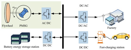
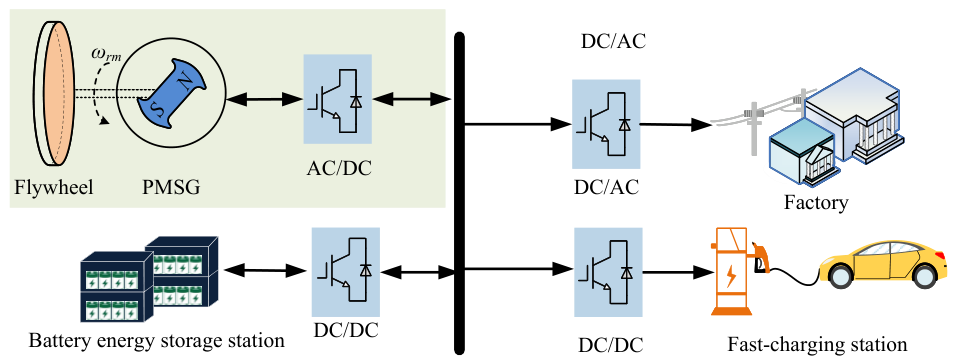
In recent years, flywheel energy storage systems (FESSs) have drawn growing interest for both academia and industry, which largely attributes to the progress in composite material technology and the distinctive benefits of FESSs, including quick transient response, minimal maintenance cost, and extended operational lifespan [1,2,3]. When FESSs are applied in DC microgrids, it is necessary to maintain the DC-link voltage to meet operational requirements in [4,5]. Otherwise, the proper functioning of critical loads and even the overall system stability could be severely compromised. A flywheel energy storage-based DC microgrid is shown in Figure 1, where permanent magnet synchronous generator (PMSG) is applied as the flywheel energy storage system.
Figure 1.
DC microgrid equipped with FESSs.
When the flywheel energy storage system operates within a DC microgrid, the flywheel speed continuously adjusts to meet the energy demands of the load in [6,7]. Furthermore, the equivalent load on the DC side will appear abrupt variations in [8,9]. The DC-link capacitance gradually declines over time due to aging or temporarily rise when additional equipment is connected to the DC bus. Such capacitance variation is an important issue because the value of capacitor directly determines the DC-link energy buffer and voltage dynamics. A reduced capacitance increases the DC-link voltage ripple and disturbance sensitivity. Consequently, the DC-link voltage may exceed its allowable range, which can deteriorate power quality and affect compliance with grid-code requirements in grid-connected FESS applications. Therefore, a DC-link voltage controller should ensure robust voltage tracking under speed, load, and capacitance variations.
To improve the DC-link voltage control performance, numerous methods for voltage control have been studied, such as voltage control methods equipped with proportional integral (PI) in [10,11], sliding model control (SMC) [12], extended state observer (ESO) [13] and model predictive control (MPC) [14]. In [11], a PI controller is employed in voltage loop to generate reference current for the inner current loop. In [13], a nonlinear ESO is used to realize global linearization and for the estimation of the total disturbance. Simultaneously, to mitigate the impact of speed variations on bus voltage control, a speed-adaptive feedback rate has been devised. However, the aforementioned method achieves DC-link voltage control through localised linearisation, which is applicable only near the steady-state operating point. The motor speed significantly fluctuates for the operation of the flywheel energy storage system, which deteriorates the control performance across the entire speed range.
SMC is widely recognized for robust control of nonlinear systems under uncertainties and disturbances, hence the SMC are widely employed as DC-link voltage controllers [15]. Nevertheless, the robustness of SMC is usually obtained at the expense of increased control gains, and excessive gains tend to induce pronounced chattering, potentially stimulating high-frequency dynamics [16]. To deal with the problems, many improved SMC strategies have been proposed, such as sliding mode control based on improved convergence rate, observer-based sliding mode control, and higher-order sliding mode control.
In [17], an outer-loop SMC with an integral switching surface and an improved exponential reaching law is proposed for voltage regulation in PMSG system. The proposed method can attenuate chattering while improving load-step transients and eliminating steady-state DC-link voltage error, which has been validated by experiments. For the purposes of improve the dynamic performance of the DC-link voltage for the FESSs, an nonlinear function is employed to replace the sign or sat function of the SMC controller in [18]. Although increasing the convergence rate can mitigate sliding mode oscillations, this comes at the cost of increased system complexity, thereby necessitating the design of additional parameters. Moreover, the high-order sliding model methods are regarded as an alternatively strategy to suppress the chatting phenomenon in [19,20,21,22].
Owing to the simple structure and robust performance, the super-twisting sliding mode control (STSMC) has received significant attention within both industry and academia. However, the super-twisting sliding mode algorithm requires that the disturbance be bounded. To address this limitation, an observer was introduced into the STSMC [23]. In [24], a reduced extended state observer (RESO) is incorporated into the sliding model speed controller. System uncertainties including parameter mismatches and unmodeled dynamics are lumped into a total disturbance, which is estimated by the RESO and then compensated. Based on the same idea, in [25], a load observer based on sliding mode is proposed to further improve the anti-load disturbance capability for the SMC method. In [26], a super-twisting nonlinear extended state observer incorporated with robust integral of the sign of the error is developed to estimate the load disturbance for the servo system. However, when embedded within sliding mode controllers, the aforementioned observers require complex parameter design and feature relatively intricate structures.
Based on the above analysis, a capacitor-energy-based super-twisting sliding mode controller (CE-STSMC) with a simple nonlinear disturbance observer (NDOB) is proposed in this article to enhance the disturbance-rejection capability of flywheel energy storage systems (FESSs), where the dominant disturbances mainly arise from sudden load application and the wide-range speed variation during the discharge process. First, the mathematical model based on the capacitive energy is established and analyzed. Based on the capacitive energy model, the CE-STSMC is designed to enhance the system robustness. Moreover, an adaptive continuous function is introduced to replace the discontinuous signum function, thereby alleviating chattering. In addition, considering the influence of total disturbance in the control system of FESSs, especially load and speed disturbances, an NDOB is introduced. The proposed CE-STSMC leverages high-order sliding-mode features to mitigate observer-induced chattering while enhancing disturbance estimation accuracy. The system robustness is further enhanced by feeding the estimated total disturbance into the CE-STSMC. Finally, the superiority of the proposed method are verified by the experiments.
The rest of this article is organized as follows. Section 2 establishes the mathematical model based on capacitive energy. Section 3 presents a NDOB integrated into the STCEC for improving the system robustness. Section 4 provides the simulation and experimenta results that demonstrted the effectiveness of the proposed method, followed by the conclusion.
2. Capacitor-Energy-Based FESSs Model
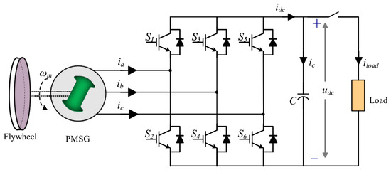
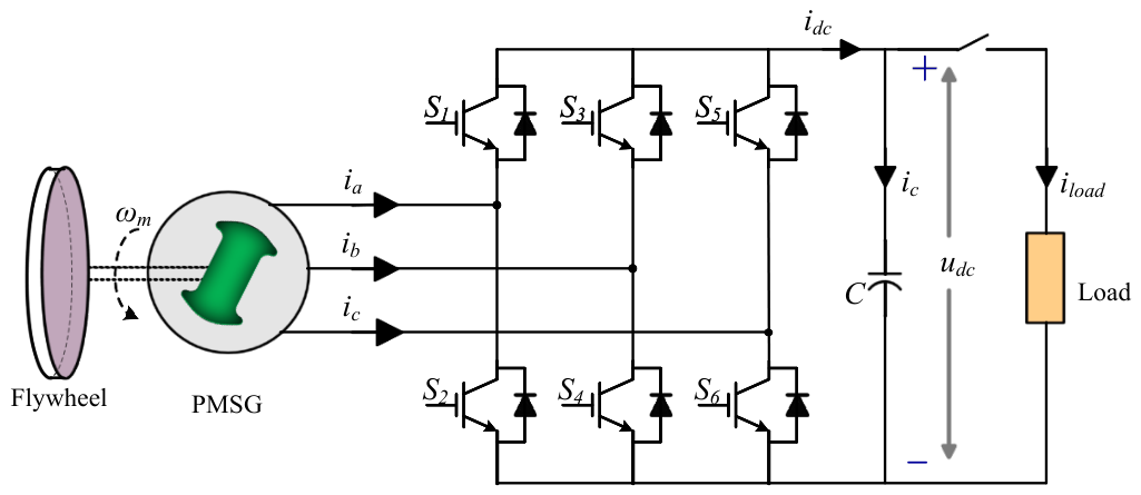
Figure 2 shows the topology of a flywheel energy storage system based on a permanent magnet synchronous motor (PMSM). The primary structure of FESSs is composed of PMSM coupled with a coaxial flywheel for kinetic energy storage, a three-phase bidirectional converter, capacitors on the DC link, and an equivalent DC load. In Figure 2, C represents the DC-link capacitor, stands for equivalent load, encompassing both linear and nonlinear components. is the DC-link current, and represents the load current. Based on the synchronous rotating coordinate transformation, the mathematical model of FESSs can be expressed as [27]
where , , , , and are the d- and q-axes components of current, voltage and inductance, respectively; p is the differential operator, i.e., ; , and are flux linkage, number of pole pairs and electromagnetic torque, and represents DC-link voltage, respectively.
Figure 2.
The main circuit of the FESSs.
The power balance equation between the two sides of the converter in the FESS can be expressed as
where is the switching loss and the negative sign indicates that the permanent magnet synchronous motor is operating in generator mode.
Substituting (1) into (2), then
It can be observed that the DC-link voltage loop is nonlinear; therefore, the traditional PI controller cannot achieve satisfactory performance. In order to linearize (3), the process of energy transfer is subsequently taken into account, and (3) can be rewritten as
where is the load power, is the copper power of the PMSM, is the inductive energy storage power.
When the power loss is treated as total consumed power, the (4) is derived as
where , .
3. Proposed Robust Voltage Control Method for FESSs
As previously discussed, the FESS is sensitive to the load disturbance when controlled by a conventional proportional–integral (PI) regulator, making it challenging to maintain satisfactory dynamic performance. Sliding mode control (SMC) is recognized for its strong robustness against system uncertainties and external disturbances in [28,29]; nevertheless, the inherent chattering effect significantly restricts its practical application. To address this issue, a super-twisting sliding mode voltage controller is developed to enhance disturbance rejection while reducing chattering behavior. Moreover, a nonlinear disturbance observer is designed to further strengthen the robustness of the system, particularly against load variations. The observer continuously estimates load disturbances in real time, and the estimated value is employed as a feedforward term to compensate for the controller’s output.
3.1. Capacitor-Energy-Based Super-Twisting Sliding Mode Controller Design
Considering the control objectives of the FESSs and the design principle of the STSMC, the variable of the system is defined as
where denotes the reference value of the DC-link capacitor energy, given by , with being reference DC-link voltage, respectively.
Then, the sliding surface is defined as
By differentiating (7) and combining it with the capacitor-energy dynamics in (5), the derivative of the sliding variable can be obtained as
Since is constant within each control interval, , and thus
In this paper, the STSMC output u is regarded as the desired reaching law of the sliding variable, namely
where the improved STSMC out u is designed as
where u and are control laws of STSMC, , , and are the positive switching gains, respectively. and are the exponent gains.
Compared to traditional STSMC, the enhanced STSMC incorporates an additional nonlinear term and a linear term . The added term can increase the convergence rate of the sliding mode controller when > 1. Therefore, the dynamic performance of the STSMC can be improved.
Therefore, the reference q-axis current can be obtained from
Substituting the STSMC law in (9) into the above equation yields
To alleviate the chattering effect caused by the discontinuous signum function, a continuous switching function is introduced to replace in the STSMC law. In this paper, is constructed as
where is the initial boundary layer width, represents exponential decay factor. It can be found that the proposed function possesses the following properties: When approaches zero, the function approaches , which forms a local linear region around the equilibrium, reducing steady-state chattering. And when approaches infinity, the function approaches , which guarantees fast convergence in the transient stage.
Finally, the control law is derived as
The influence of measurement noise and parameter uncertainties can be regarded as bounded lumped disturbances in the sliding-mode dynamics. Since the proposed super-twisting sliding mode controller is designed under bounded disturbance conditions, the closed-loop system can still maintain finite-time convergence when the control gains are properly selected. Moreover, the disturbance observer compensates the low-frequency load disturbance and parameter mismatch, while the continuous control law of the super-twisting algorithm helps reduce the chattering caused by measurement noise. Therefore, the proposed method is expected to be robust against measurement noise and parameter uncertainties.
The parameters of the proposed STSMC are determined by balancing the convergence speed and chattering suppression. Specifically, and are used to regulate the nonlinear reaching rate, is adopted to improve the response speed for large sliding errors, and determines the updating speed of the auxiliary variable . Meanwhile, and are used to adjust the variation rate of the continuous switching function, respectively. In this paper, the parameters are set as Table 1.
Table 1.
Parameter selection of the proposed STSMC.
Stability Analyses
Consider the Lyapunov candidate function
Then combining (10) and (15), the derivative of Lyapunov candidate function is
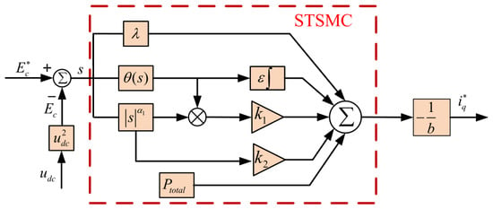
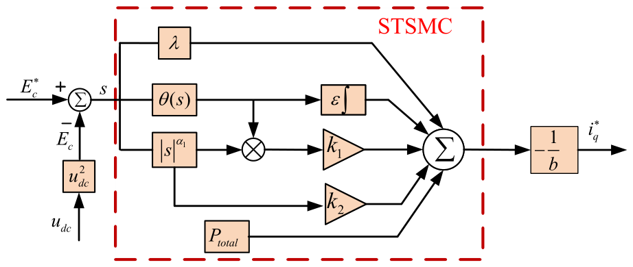
where is a positive constants. With an adequately chosen , the inequality holds without difficulty. According to Lyapunov stability analysis, the voltage loop fulfills the reaching condition, guaranteeing finite-time convergence of the sliding motion and overall system stability under the CE-STSMC control law. The configuration of the voltage outer-loop controller employing the CE-STSMC algorithm is depicted in Figure 3.
Figure 3.
Block diagram of the STSMC.
3.2. Design of the Nonlinear Disturbance Observer
As can be seen in (15), the control law includes unknown total loss power, which will affect the selection of controller parameters. Although large control gain can overcome the effect of the disturbance, it will lead large chattering. However, observing disturbances through an observer and compensating for them can reduce controller gain, thereby minimizing chattering. Thereby, an NDOB is designed to estimate the total loss power online. Then the estimated disturbance can be feedforward into the CE-STSMC.
According to (5), the NDOB can be designed as
where , m and are the estimated values for the internal variables of the detector, the gain coefficient, and the estimated total loss power; the is the function to be designed, where can be taken here.
The estimated error in defining the total power loss is defined as
Then the derivative of the error is
For the real flywheel energy storage systems, the total power loss is bounded, and the derivative approaches zero. Hence, when the gain m is positive, the estimated error will converge to zero as time approaches infinity, which means the observer can estimate the total power loss. Moreover, the convergence rate of the observer is determined by m; the faster convergence rate can be achieved with a larger value of m. In practical implementation, m is selected by considering both the convergence rate and the noise sensitivity of the observer. In this paper, is adopted in experiments, which provides a satisfactory compromise between fast convergence and smooth estimation.
By applying the Laplace transform to (18), the transfer function of the observer can be obtained as
It can be seen in (22) that the NDOB possesses low-pass filtering characteristics. Consequently, the output values require no further filtering and can effectively reduce the ripple of observed disturbances. Simultaneously, since the estimated total power loss of the observation contains the approximate differential of , an excessively large m value will increase measurement noise, adversely breaking system stability.
After integrating the disturbance estimation mechanism, the final composite control law for the voltage control is derived by feeding the observed total power loss into the STSMC, as follows:
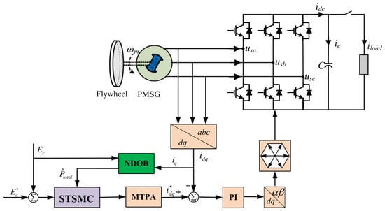
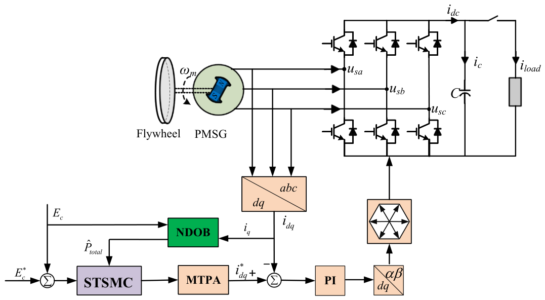
The overall control structure of the proposed method is presented in Figure 4. The super-twisting sliding-mode controller (STSMC) is employed in the outer loop to regulate the DC-link voltage and generate q-axis reference current for inner current loop. Meanwhile, a nonlinear disturbance observer (NDOB) estimates the lumped disturbance online and provides feedforward compensation to enhance robustness. The inner current loop is implemented in the synchronous frame with PI regulators, whose gains are designed via the pole-zero cancellation method [30]. In addition, an MTPA block is incorporated to improve efficiency by allocating the d-axis current reference.
Figure 4.
Control block diagram of the proposed method.
3.3. Stability Analysis of the Proposed Method
To demonstrate the stability of the proposed method, the candidate Lyapunov function is
Combined with the (14) formula, the derivative of the candidate Lyapunov function is
Both and are bounded. This means there must exist constants and such that
where ,
Based on (26), the boundedness of is ensured, and consequently the trajectories of s and are uniformly bounded throughout the convergence process. Thus, prior to the finite-time bounded convergence of the observer errors, neither s nor can exhibit unbounded growth.
Next, the convergence property of the sliding variable is further analyzed. Considering the observer estimation error, the closed-loop sliding-mode dynamics can be written as
According to the stability analysis of the observer, is bounded in finite time. Thus, there exists a positive constant such that .
The Lyapunov candidate function is selected as
Taking the derivative of gives
Since
and , one obtains
For the case of , where is a prescribed small boundary layer, the derivative of can be expressed as
As the control gains are designed to satisfy
then for . Therefore, the sliding variable can converge to the boundary layer .
For the case of , the continuous function behaves as a local linear function around the origin. Therefore,
When the observer estimation error converges to zero, , and thus . Hence, the sliding variable asymptotically converges to zero inside the boundary layer. When the observer estimation error is bounded, the sliding variable is ultimately bounded by a small neighborhood around the origin.
Consequently, the proposed controller-observer structure is practically finite-time stable. The sliding variable reaches a small boundary layer in finite time and further converges to zero if the observer estimation error vanishes.
4. Experimental Result
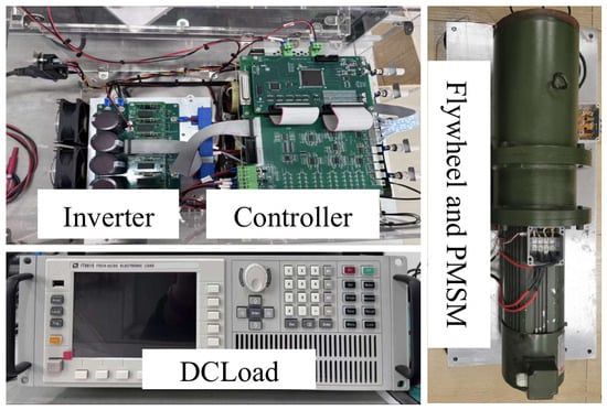
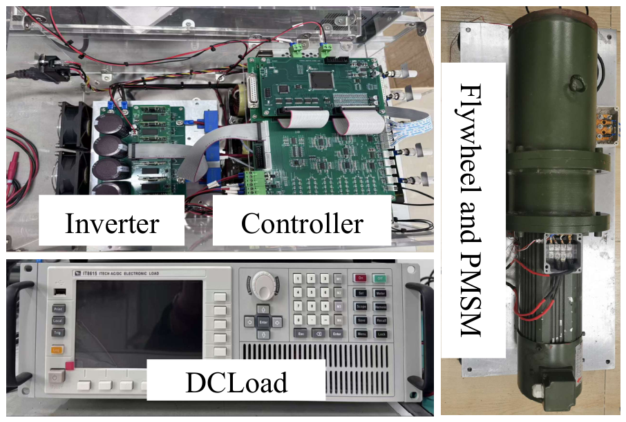
To verify the effectiveness of the proposed method in this article, the experiments have been carried out. The parameters of the FESSs are listed in Table 2. The experimental platform is shown in Figure 5. A DC power supply is employed to accelerate the permanent magnet synchronous motor within the flywheel energy storage system to a predetermined rotational speed, thereby storing energy within the high-speed rotating flywheel. Subsequently, the DC bus is disconnected. The three-phase voltage-source inverter utilises intelligent power module (IPM). The proposed algorithm is implemented on a Texas Instruments TMS320F28335 processor (Texas Instruments, Dallas, TX, USA), where both the sampling and switching frequencies are set to 10 kHz. The DC-link voltage is measured using the LV25-P voltage module (LEM International SA, Meyrin, Switzerland). The block diagram of the proposed discharge methods is presented in Figure 4. To demonstrate the superiority of the proposed algorithm, traditional PI and NDOB are employed as comparison methods.
Table 2.
Parameters of the FESSs.
Figure 5.
Experimental setup for FESSs.
4.1. Tracking Performance Analysis
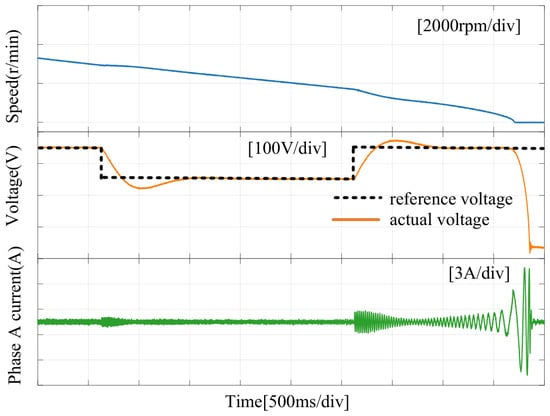
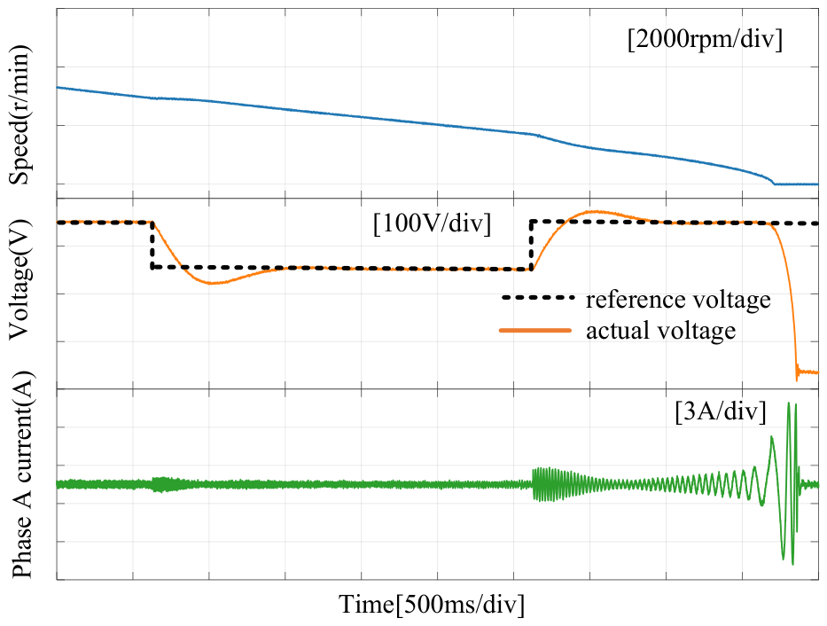
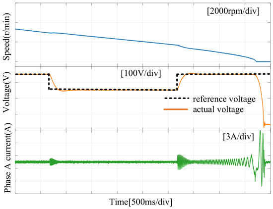
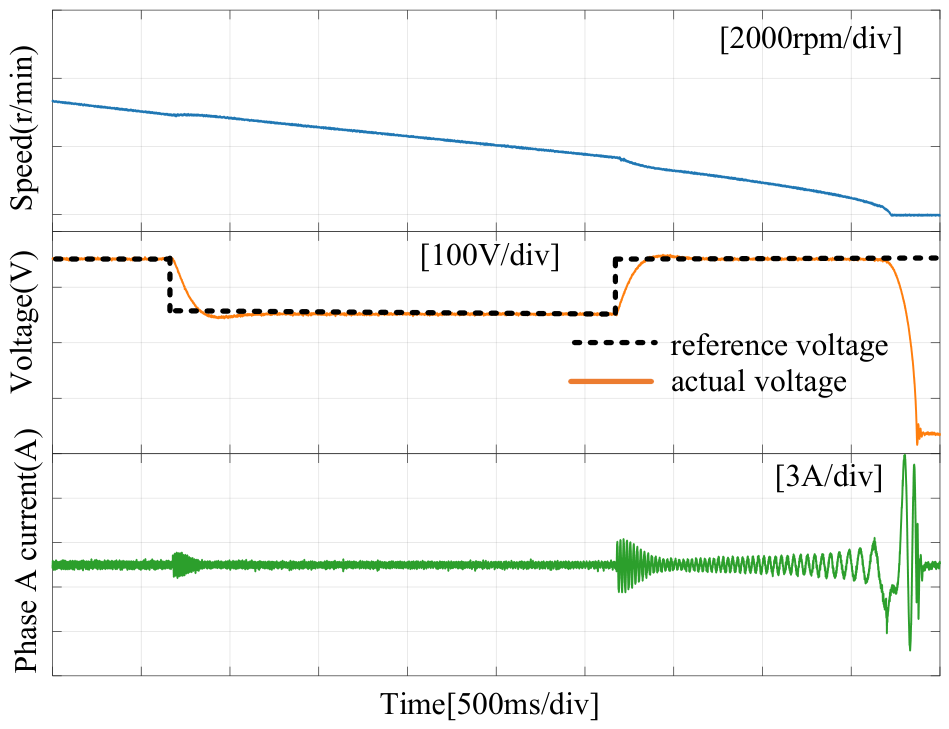
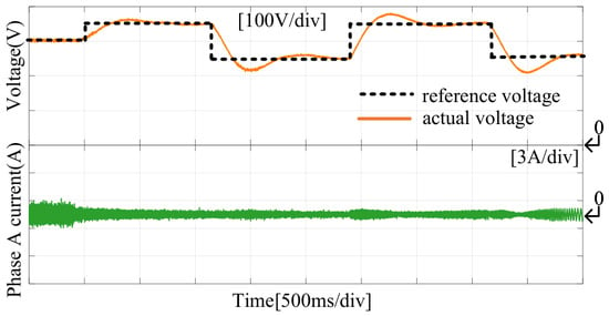
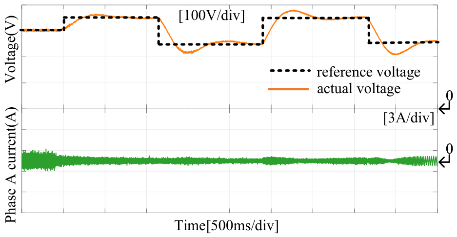
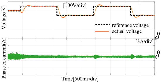
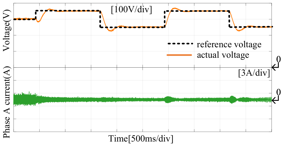
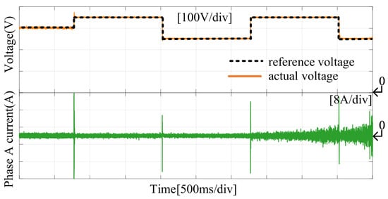
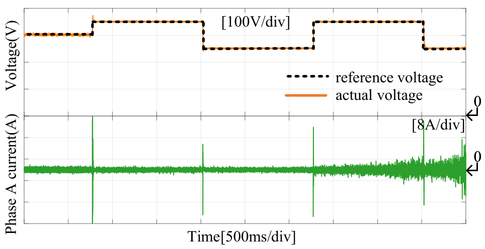
As shown in Figure 6, Figure 7 and Figure 8, the DC-link voltage tracking responses under different control schemes are compared with initial speed of 4500 r/min. During the voltage tracking process, the reference voltage is stepped down from 350 V to 250 V and then restored from 250 V to 350 V. Although all methods can regulate DC-link voltage to the command value, the dynamic performances are significantly different. The responses in Figure 6 and Figure 7 suffer from evident oscillation and voltage fluctuation during the step-change process. In comparison, the responses in Figure 8 present superior dynamic behavior, characterized by smoother transients, smaller overshoot, and faster convergence. Therefore, the proposed strategy behaves higher voltage tracking and stronger transient robustness under sudden command changes.
Figure 6.
The tracking performance of DC-link voltage with reference voltage step using PI.
Figure 7.
The tracking performance of DC-link voltage with reference voltage step using NDOB.
Figure 8.
The tracking performance of DC-link voltage with reference voltage step using proposed method.
The above experimental results show that the q-axis current increases rapidly when the flywheel speed decreases to a very low level during the final discharge stage. This phenomenon is closely related to the physical discharge limit of the flywheel energy storage system. At very low speed, the flywheel system reaches its physical discharge limit. Since the electromagnetic power maintain the same discharge power requires a larger q-axis current as the speed decreases. When the speed approaches zero, the required current will increase. Therefore, in the practical implementation, a q-axis current saturation is introduced. Once the current limit is reached, the discharge process is terminated to avoid overcurrent and excessive DC-bus voltage drop.
4.2. Load Disturbance Suppression Analysis
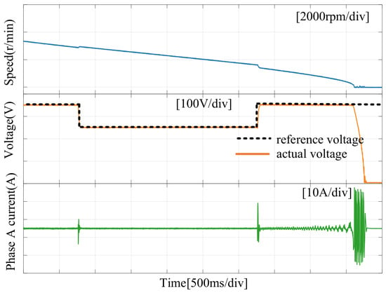
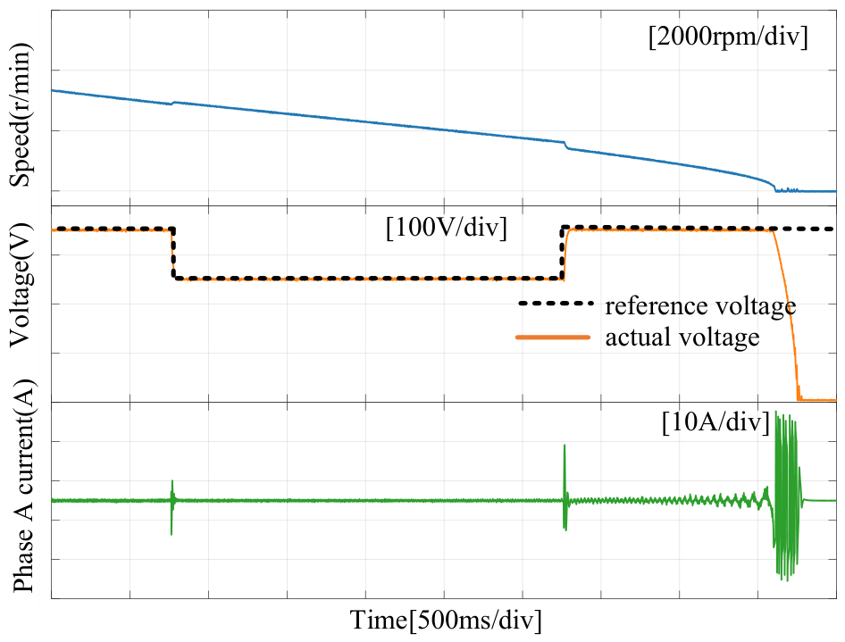
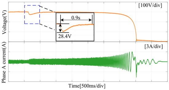
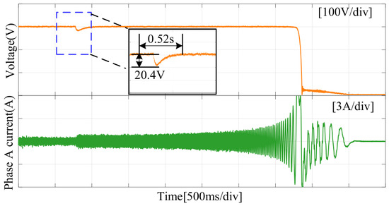
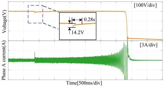
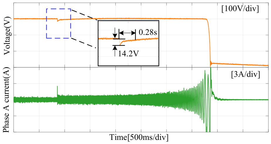
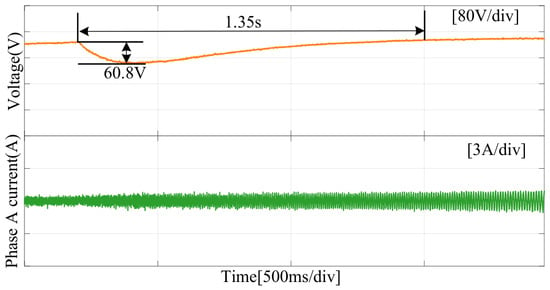
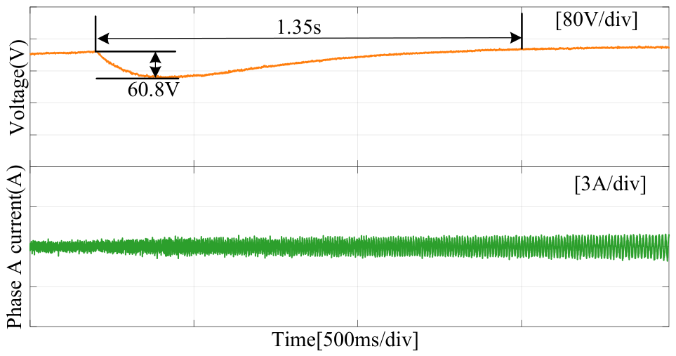
In order to verify the load disturbance ability, Figure 9, Figure 10 and Figure 11 represent the performance of different methods under sudden load changes. During the experiments, the bus voltage is set as 300 V, and a resistance of 950 is suddenly applied. It can be seen that under the sudden load situation, under a sudden load change, the DC-link voltage drops to 28.4 V and 20.4 V for the PI and NDOB control schemes respectively, with recovery times of 0.9 s and 0.52 s, respectively. On the contrary, the lowest voltage drop and shortest recovery time can be obtained with the proposed method. The proposed method exhibits excellent dynamic performance since the improved STSMC can rapidly generate the q-axis reference current. At the same time, the NDOB can also provide feedforward compensation for sudden load disturbances, causing the phase current to increase rapidly and accelerating the conversion of kinetic energy into electrical energy. Therefore, the disturbance rejection capability of the proposed method against sudden load application can be verified.
Figure 9.
The tracking performance of DC-link voltage with load step using PI.
Figure 10.
The tracking performance of DC-link voltage with load step using NDOB.
Figure 11.
The tracking performance of DC-link voltage with load step using proposed method.
In order to provide a comparison with the existing method in [24], the DFTSMC method is additionally included in the sudden-load experiment at 6000 r/min. It can be observed from Figure 9, Figure 10, Figure 11 and Figure 12 that the DC-link voltage drops in both the proposed method and the other schemes at the end of the discharge process. This phenomenon can be interpreted from (5). As the flywheel speed continuously declines, the required q-axis current rises sharply and theoretically tends to infinity as the speed approaches zero, which is physically unrealizable. Therefore, in the experimental implementation of all the methods, the speed used in the controller is clamped to a small constant value once it falls below a near-zero threshold. Under this condition, the reference q-axis current can no longer provide sufficient compensation to maintain the DC-link voltage constant. The same effect can also be observed in the subsequent experimental results.
Figure 12.
The tracking performance of DC-link voltage with load step using DFTSMC.
Table 3 gives the quantitative performance comparison of different control methods. It can be observed that the proposed method achieves lower overshoot, shorter settling time, and smaller steady-state error than PI, NDOB, and DFTSMSC, which further demonstrates its superior dynamic response and steady-state regulation performance.
Table 3.
Quantitative performance comparison of different methods.
4.3. Robustness Comparison
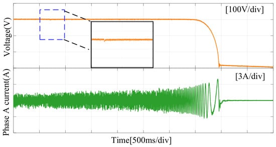
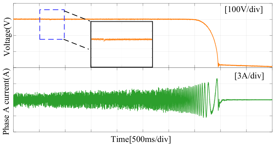
To demonstrate the robustness of the proposed method, experiments were conducted under different capacitance conditions. Figure 13, Figure 14, Figure 15, Figure 16, Figure 17 and Figure 18 show the experimental results of the voltage tracking and sudden load tests under the condition of , where is the real value of the capacitor in FESSs. The condition of is considered since of the rated capacitance can be viewed as the allowable lower limit in practical operation, and the effect of capacitance reduction on the controller performance becomes more significant under this condition.
Figure 13.
The tracking performance of DC-link voltage with reference voltage step using PI under .
Figure 14.
The tracking performance of DC-link voltage with reference voltage step using NDOB under .
Figure 15.
The tracking performance of DC-link voltage with reference voltage step using proposed method under .
Figure 16.
Dynamic responses of PI under a sudden load step with .
Figure 17.
Dynamic responses of NDOB under a sudden load step with .
Figure 18.
Dynamic responses of the proposed method under a sudden load step with .
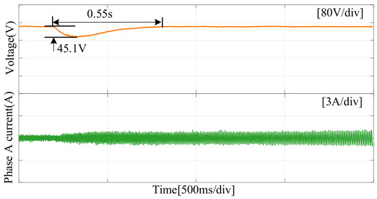
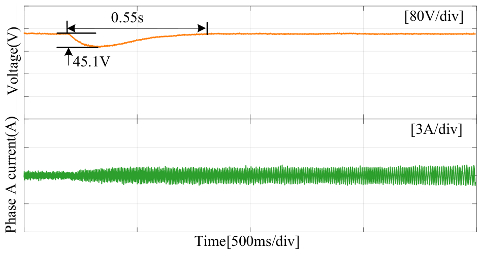
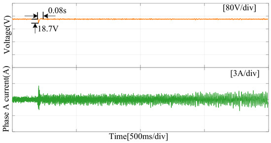
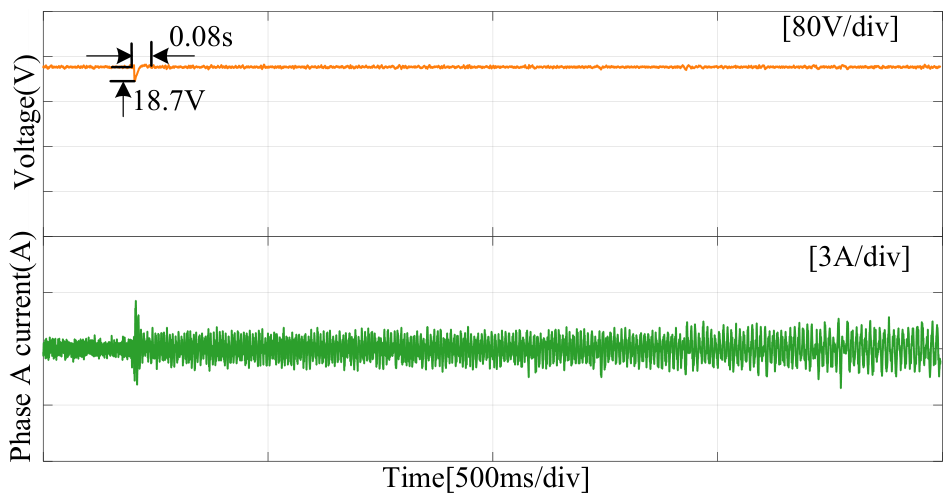
Compared with the nominal capacitance condition shown in Figure 6, Figure 7 and Figure 8 for the voltage tracking test and Figure 9, Figure 10 and Figure 11 for the sudden load test, the PI controller and the NDOB-based method exhibit significantly degraded performance when the capacitance varies. Specifically, the voltage tracking performance is severely broken, while a larger DC-link voltage drop and a longer recovery time is clear under sudden load disturbance. These results indicate that the performances of the PI controller and the DOB-based method are significantly affected by the capacitance variation. In contrast, the performance of the proposed method is almost unaffected, thereby demonstrating its strong robustness and superior control performance even under capacitance variation.
4.4. Total Disturbance Estimation Based on DOB
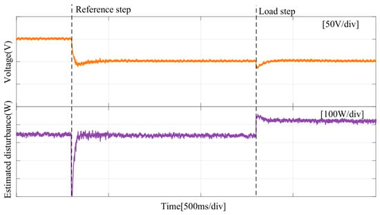
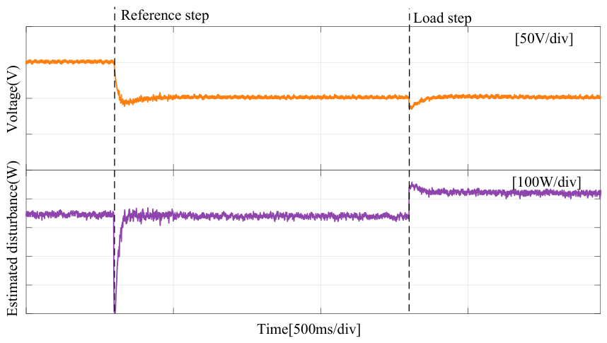
Figure 19 illustrates the DC-link voltage response and the estimated total disturbance under a reference step and a load step. When the reference step is applied, the DC-link voltage exhibits a short transient drop and quickly settles to the steady state, indicating an effective dynamic response. Correspondingly, the estimated disturbance shows a sharp negative peak, which reflects the rapid variation induced by the reference change. The disturbance estimate then converges quickly with small steady-state fluctuation, demonstrating good convergence and noise immunity. When the load step occurs, only a slight voltage deviation is observed, and the voltage is restored within a short duration, indicating strong disturbance rejection capability. Meanwhile, the estimated disturbance increases promptly to a new steady-state level, accurately capturing the effect of the external disturbance. It should be noted that the estimated disturbance by the NDOB in Figure 19 is a lumped disturbance rather than the pure load power, which includes the effects of load variation, system losses, and model uncertainties.
Figure 19.
DC-link voltage tracking performance with reference voltage step using proposed method.
Overall, the results verify that the proposed NDOB can achieve fast and accurate observation under both reference variation and external disturbance, thereby effectively improving the dynamic and steady-state performance of the DC-link voltage control.
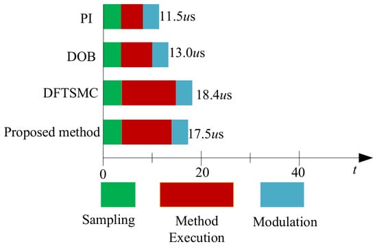
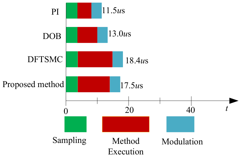
To more comprehensively evaluate the performance of the proposed method, it is necessary to consider the computational overhead of the algorithm during runtime, as shown in Figure 20. From Figure 20, it can be viewed that the total execution time includes sampling, control algorithm execution, and modulation calculation. Under the 10 kHz voltage-loop frequency, the available control period is 100 μs. The execution times of PI, DOB, DFTSMC, and the proposed method are 11.5 μs, 13.0 μs, 18.4 μs, and 17.5 μs, respectively. Although the proposed method introduces a disturbance observer and an improved super-twisting sliding mode controller, its execution time is still much shorter than the control period and lower than that of DFTSMC, indicating that the proposed method has acceptable computational complexity and sufficient real-time implementation margin.
Figure 20.
Execution time comparison of different control methods.
5. Conclusions
This article proposes a capacitor-energy-based super-twisting sliding mode controller integrated with an NDOB for DC-link voltage control of FESSs. The proposed control framework mainly consists of two parts: (1) the design of a capacitor-energy-based DC-link voltage controller using the STSMC, and (2) the construction of an NDOB to estimate the total disturbance caused by load variations, parameter mismatches, and wide-speed-range operation. The main conclusions are summarized as follows.
- An enhanced STSMC has been developed by introducing an additional nonlinear term and an adaptive continuous function. This design improves the convergence rate and simultaneously suppresses the chattering effect.
- The proposed NDOB can estimate the total disturbance in real time with fast transient response and high estimation accuracy, thereby improving the disturbance rejection capability of the overall system.
- Experimental results confirm that the proposed method achieves satisfactory DC-link voltage control performance and exhibits strong robustness under disturbances and varying operating conditions.
Author Contributions
Conceptualization, L.L.; methodology, L.L.; software, Z.X.; validation, Z.X. and J.X.; formal analysis, J.X.; investigation, L.L.; resources, L.L.; data curation, Q.X.; writing—original draft, L.L.; writing—review and editing, Q.X.; visualization, L.L.; supervision, Z.X.; project administration, Z.X.; funding acquisition, Z.X. All authors have read and agreed to the published version of the manuscript.
Funding
This research was funded by Science and Technology Project of China Southern Power Grid Co., Ltd., 030100KC24060020 (GDKJXM20240491).
Data Availability Statement
The data supporting the findings of this study are available from the corresponding author upon reasonable request.
Conflicts of Interest
All authors were employed by the Guangzhou Power Supply Bureau of Guangdong Power Grid Co., Ltd. All authors declare that the research was conducted in the absence of any commercial or financial relationships that could be construed as a potential conflict of interest. The authors declare that this study received funding from China Southern Power Grid Co., Ltd. The funder was not involved in the study design, collection, analysis, interpretation of data, the writing of this article or the decision to submit it for publication.
References
- Ye, C.; Yu, D.; Liu, K.; Dai, Y.; Deng, C.; Yang, J.; Zhang, J. Research of a stator PM excitation solid rotor machine for flywheel energy storage system. IEEE Trans. Ind. Electron. 2022, 12, 12140–12151. [Google Scholar] [CrossRef] [Scilit]
- Qi, Z.; Zhang, Y.; Yu, S. Design and analysis of the multilayer sleeve structure for the rotor eddy current loss reduction of a high-speed permanent magnet motor for flywheel energy storage system. IEEE Trans. Transp. Electrif. 2025, 5, 11398–11409. [Google Scholar] [CrossRef] [Scilit]
- Xu, K.; Guo, Y.; Lei, G.; Zhu, J. Sensorless control of high-speed PMSM based on cascade high-order extended state observer for flywheel energy storage system. IEEE Trans. Ind. Electron. 2026, 73, 1738–1749. [Google Scholar] [CrossRef] [Scilit]
- Chen, Y.; Yang, J.; Zhang, X.; Yan, L.; Jia, Y. DC-bus voltage control for FESSs with capacitor energy regulation and tracking differentiator. IEEE Trans. Transp. Electrif. 2026, 1, 8077–8090. [Google Scholar] [CrossRef] [Scilit]
- Liang, Y.; Liang, D.; Kou, P.; Jia, S.; Chu, S.; Wang, H.; Liang, Y. Linear robust discharge control for flywheel energy storage system with RLC filter. IEEE Trans. Ind. Appl. 2022, 58, 6175–6189. [Google Scholar] [CrossRef] [Scilit]
- Maroufi, S.M.; Karrari, S.; Rajashekaraiah, K.; Carne, G. Power management of hybrid flywheel-Battery energy storage systems considering the state of charge and power ramp rate. IEEE Trans. Power Electron. 2025, 40, 9944–9956. [Google Scholar] [CrossRef] [Scilit]
- Chen, Y.; Zhang, X.; Li, S.; Yang, J. Power capacitance energy control for FESSs: Tracking performance analysis and robust design against variations of speed, load, and capacitance. IEEE Trans. Energy Convers. 2024, 39, 974–987. [Google Scholar] [CrossRef] [Scilit]
- Belguedri, M.; Amirat, Y.; Benrabah, A.; Khoucha, F.; Benbouzid, M.; Benmansour, K. Active disturbance rejection control with a cascaded extended state observer for pumping kite generator systems robust DC-link voltage control. IEEE Trans. Energy Convers. 2025, 40, 1178–1189. [Google Scholar] [CrossRef] [Scilit]
- Zhao, M.; Zhang, S.; Zhang, C.; Li, X.; Dong, Y. Improved DC-link voltage sliding mode control for permanent magnet synchronous generator systems with three-phase AC-DC converters. IEEE J. Emerg. Sel. Top. Power Electron. 2025, 13, 2285–2295. [Google Scholar] [CrossRef] [Scilit]
- Zhang, X.; Yang, J. A DC-Link voltage fast control strategy for high-speed PMSM/G in flywheel energy storage system. IEEE Trans. Ind. Appl. 2018, 54, 1671–1679. [Google Scholar] [CrossRef] [Scilit]
- Sun, B.; Dragicevic, T.; Freijedo, D.; Vasquez, J.; Guerrero, J.M. A control algorithm for electric vehicle fast charging stations equipped with flywheel energy storage systems. IEEE Trans. Power Electron. 2016, 31, 6674–6685. [Google Scholar] [CrossRef] [Scilit]
- Huang, Y.; Zhang, Z.; Huang, W.; Chen, S. DC-link voltage regulation for wind power system by complementary sliding mode control. IEEE Access 2019, 7, 22773–22780. [Google Scholar] [CrossRef] [Scilit]
- Zhang, X.; Yang, J. A robust flywheel energy storage system discharge strategy for wide speed range operation. IEEE Trans. Ind. Electron. 2017, 64, 7862–7873. [Google Scholar] [CrossRef] [Scilit]
- Zhang, C.; Zheng, Y.; Zhu, W.; Gao, R. Model predictive current control for DC-link ripple voltage suppression in electrolytic capacitor-less drive system. Energies 2022, 15, 9297. [Google Scholar] [CrossRef] [Scilit]
- Li, W.; Ji, J.; Dong, H.; He, M.; Hu, S. Power allocation control strategy of DC/DC converters based on sliding mode control. Energies 2024, 17, 4628. [Google Scholar] [CrossRef] [Scilit]
- Tian, M.; Wang, T.; Yu, Y.; Dong, Q.; Wang, B.; Xu, D. Integrated observer-based terminal sliding-mode speed controller for PMSM drives considering multisource disturbances. IEEE Trans. Power Electron. 2024, 39, 7968–7979. [Google Scholar] [CrossRef] [Scilit]
- Huang, J.; Zhang, Z.; Han, J.; Jiang, W. Sliding mode control of permanent magnet generator system based on improved exponential rate reaching law. IET Electr. Power Appl. 2020, 14, 1154–1162. [Google Scholar] [CrossRef] [Scilit]
- Mozayan, S.M.; Saad, M.; Vahedi, H.; Fortin-Blanchette, H.; Soltani, M. Sliding mode control of PMSG wind turbine based on enhanced exponential reaching law. IEEE Trans. Ind. Electron. 2016, 63, 6148–6159. [Google Scholar] [CrossRef] [Scilit]
- Beltran, B.; Ahmed-Ali, T.; Benbouzid, M. High-order sliding-mode control of variable-speed wind turbines. IEEE Trans. Ind. Electron. 2009, 56, 3314–3321. [Google Scholar] [CrossRef] [Scilit]
- Yang, J.; Su, J.; Li, S.; Yu, X. High-order mismatched disturbance compensation for motion control systems via a continuous dynamic sliding-mode approach. IEEE Trans. Ind. Inform. 2013, 10, 604–614. [Google Scholar] [CrossRef] [Scilit]
- Huang, J.; Zhang, M.; Ri, S.; Xiong, C.; Li, Z.; Kang, Y. High-order disturbance-observer-based sliding mode control for mobile wheeled inverted pendulum systems. IEEE Trans. Ind. Electron. 2019, 67, 2030–2041. [Google Scholar] [CrossRef] [Scilit]
- Chen, X.; Jiang, Q.; Huang, T. Chattering-free terminal sliding mode control of DOC outlet temperature with active disturbance compensation. Energies 2026, 19, 2178. [Google Scholar] [CrossRef] [Scilit]
- Hou, Q.; Ding, S. Finite-time extended state observer-based supertwisting sliding mode controller for PMSM drives with inertia identification. IEEE Trans. Transp. Electrif. 2022, 8, 1918–1929. [Google Scholar] [CrossRef] [Scilit]
- Zhang, X.; Kang, M.; Gong, C.; Yang, J.; Guerrero, J.M. Enhanced control strategy for FESSs: A derivative-free fast terminal sliding mode approach with reduced-order error-based ESO. IEEE J. Emerg. Sel. Top. Power Electron. 2026, 14, 646–658. [Google Scholar] [CrossRef] [Scilit]
- Yin, S.; Wang, X. Super twisting control design for HSPMSG voltage stabilization based on disturbance observation compensation. IEEE Trans. Energy Convers. 2023, 38, 1387–1395. [Google Scholar] [CrossRef] [Scilit]
- Wang, X.; Wang, S. Fixed-time integral terminal sliding-mode control with super-twisting nonlinear extended-state observer for servo system with disturbances. IEEE J. Emerg. Sel. Top. Power Electron. 2025, 6, 435–446. [Google Scholar] [CrossRef] [Scilit]
- Cimuca, G.; Saudemont, C.; Robyns, B.; Radulescu, M. Control and Performance Evaluation of a Flywheel Energy-Storage System Associated to a Variable-Speed Wind Generator. IEEE Trans. Transp. Electrif. 2006, 53, 1074–1085. [Google Scholar] [CrossRef] [Scilit]
- Wang, P.; Wu, Y.; Lu, J.; Xu, L.; Li, J.; Xu, B.; Wang, X.; Tian, Y. Enhanced voltage response of SMES-DVR via sliding mode control with extended state observer. IEEE Trans. Ind. Appl. 2025, 61, 9592–9601. [Google Scholar] [CrossRef] [Scilit]
- Hu, J.; Sun, Q.; Wang, R.; Wang, B.; Zhai, M.; Zhang, H. Privacy-preserving sliding mode control for voltage restoration of AC microgrids based on output mask approach. IEEE Trans. Ind. Inform. 2022, 18, 6818–6827. [Google Scholar] [CrossRef] [Scilit]
- Zhou, S.; Liu, J.; Zhou, L. DQ current control of voltage source converters with a decoupling method based on preprocessed reference current feed-forward. IEEE Trans. Power Electron. 2017, 32, 8904–8921. [Google Scholar] [CrossRef] [Scilit]

Disclaimer/Publisher’s Note: The statements, opinions and data contained in all publications are solely those of the individual author(s) and contributor(s) and not of MDPI and/or the editor(s). MDPI and/or the editor(s) disclaim responsibility for any injury to people or property resulting from any ideas, methods, instructions or products referred to in the content. |
© 2026 by the authors. Licensee MDPI, Basel, Switzerland. This article is an open access article distributed under the terms and conditions of the Creative Commons Attribution (CC BY) license.