


The authors would like to make the following corrections to the originally published paper [1].
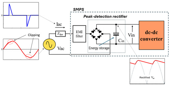
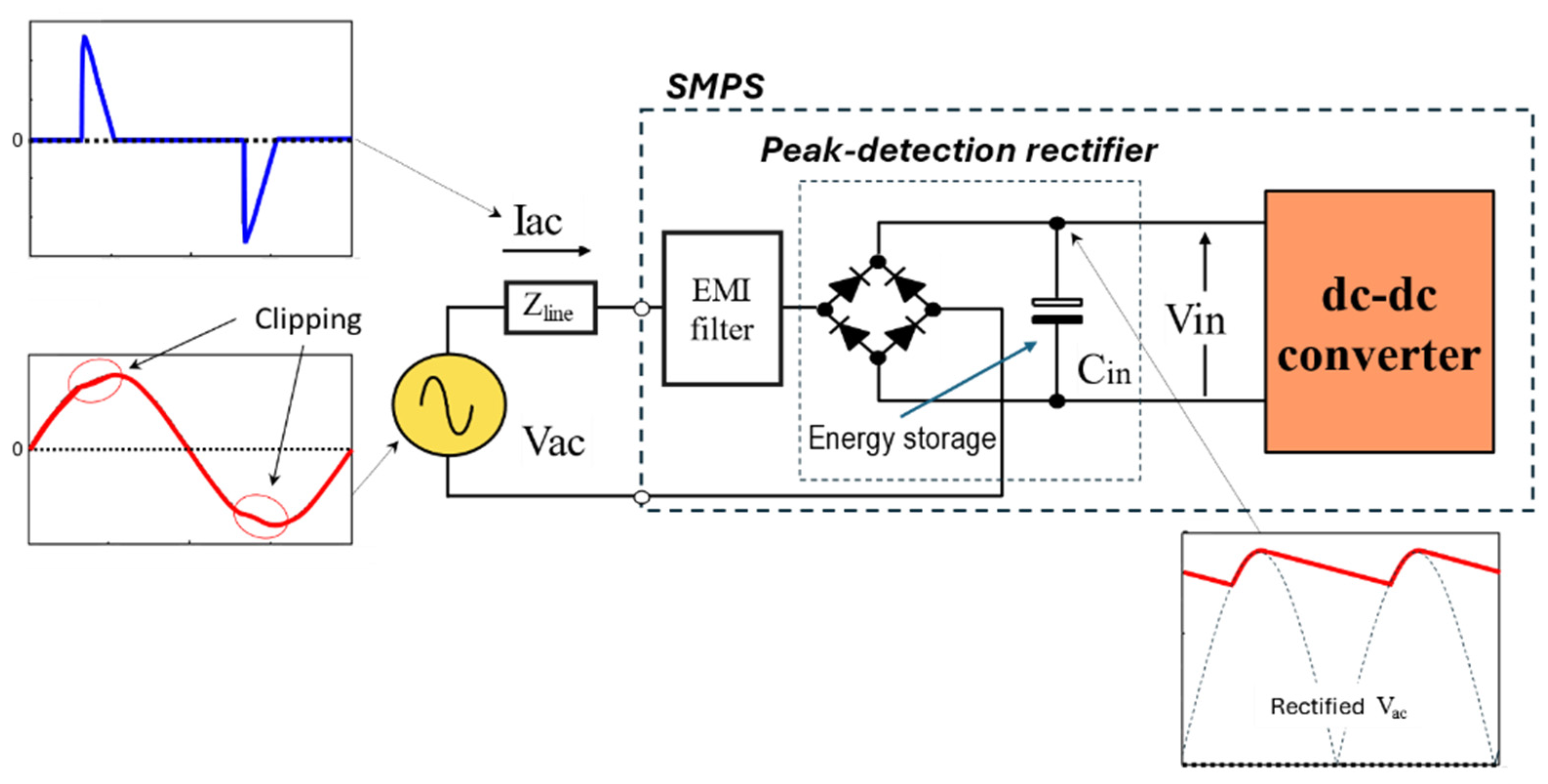
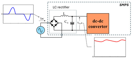
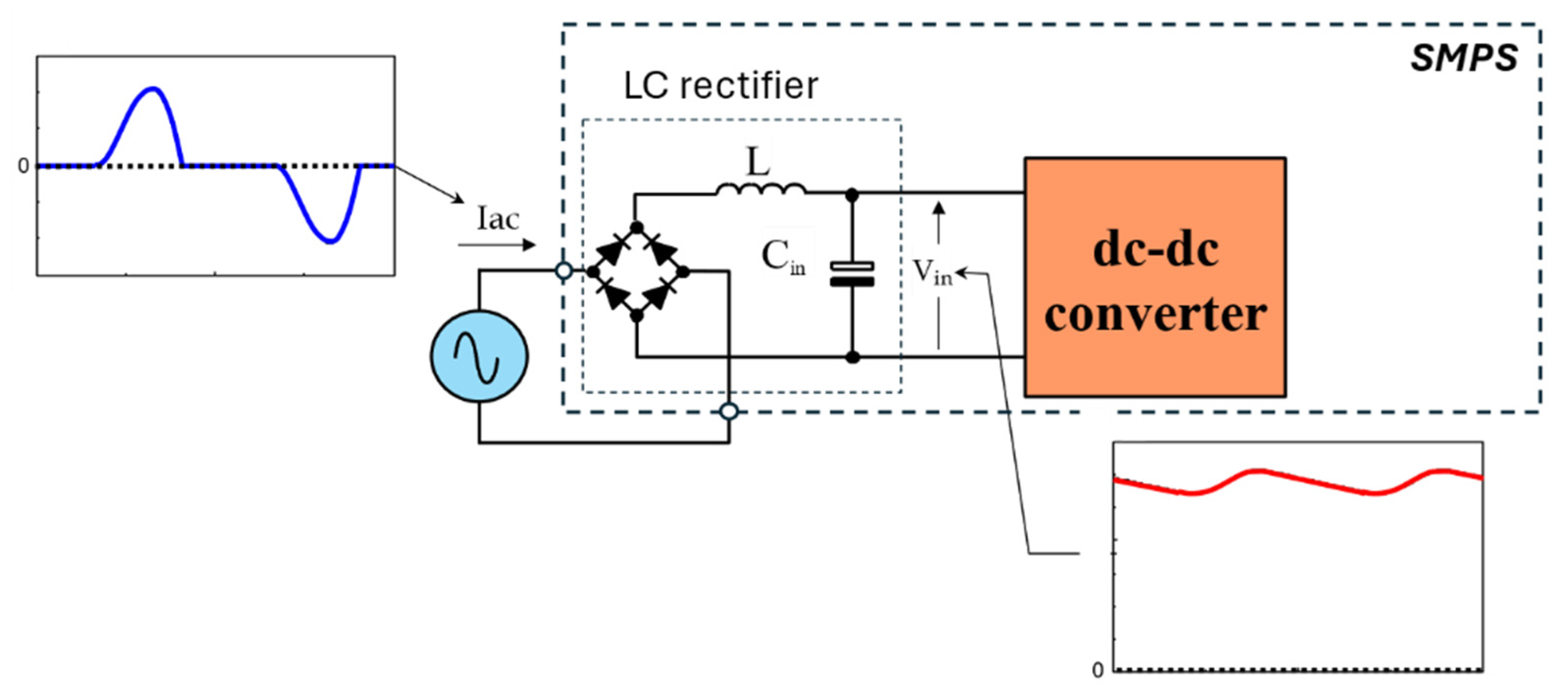
In the original publication, due to an oversight, there was a repeated mistake in Figures 1, 6–10 and 12 as published. The input bridge should be rotated by 90 degrees counterclockwise. The corrected Figure 1, Figure 6, Figure 7, Figure 8, Figure 9, Figure 10 and Figure 12 appear below. The authors state that the scientific conclusions are unaffected. This correction was approved by the Academic Editor. The original publication has also been updated.
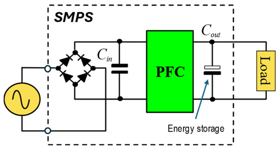
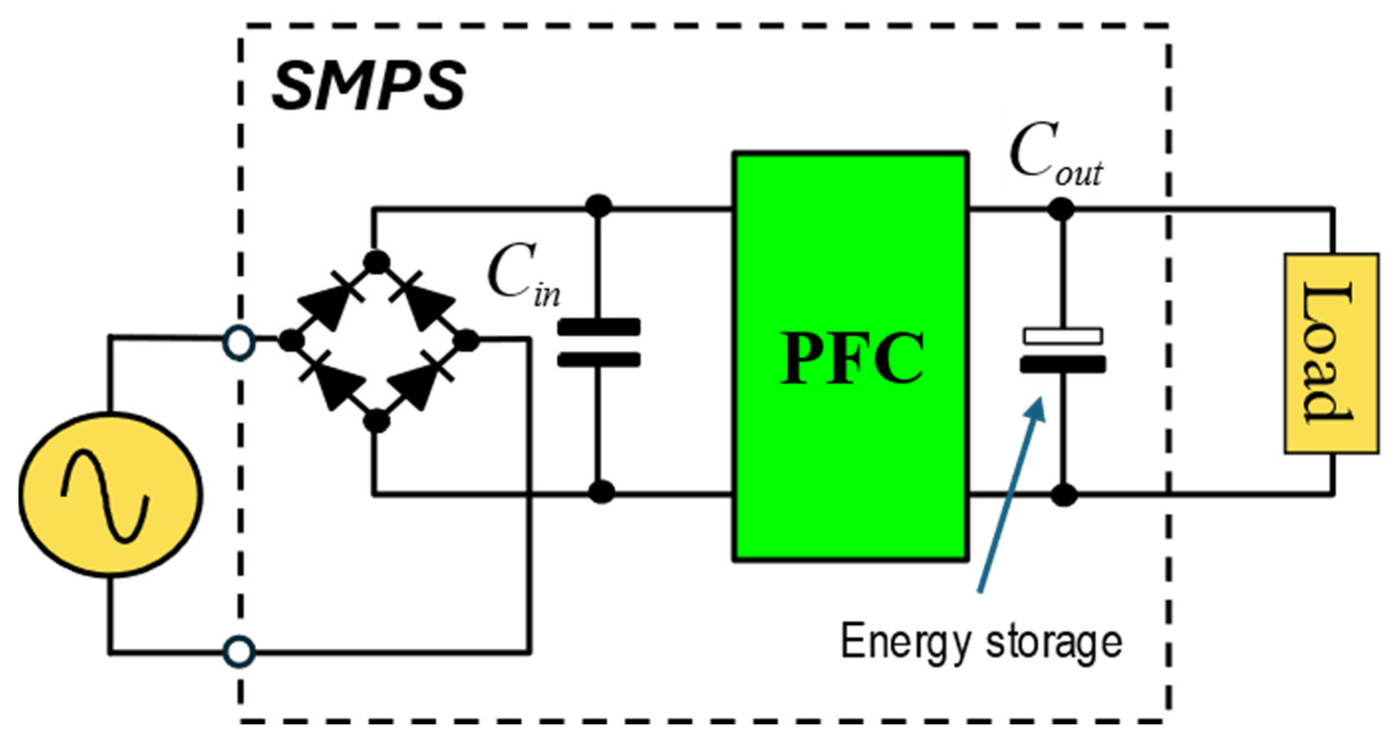
Figure 1.
Front-end of a typical SMPS and related key waveforms.
Figure 6.
An LC rectifier and related key waveforms.
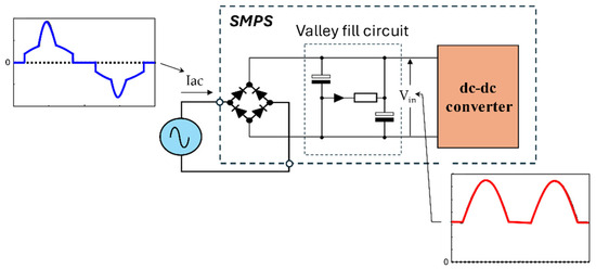
Figure 7.
A Valley Fill circuit and related key waveforms.
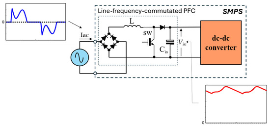
Figure 8.
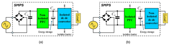
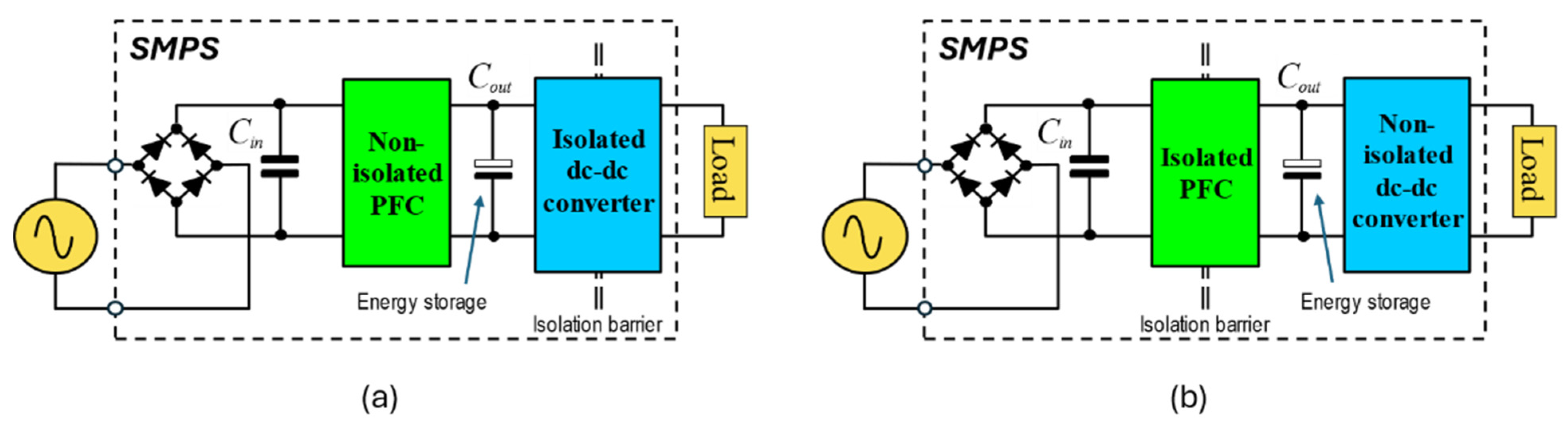
A line-frequency-commutated PFC system.
Figure 9.
Typical architectures of a power-factor-corrected SMPS: (a) with a non-isolated PFC; (b) with an isolated PFC.
Figure 10.
Single-stage power-factor-corrected SMPS for ripple-tolerant loads.
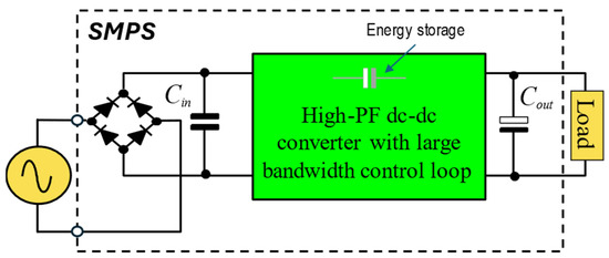
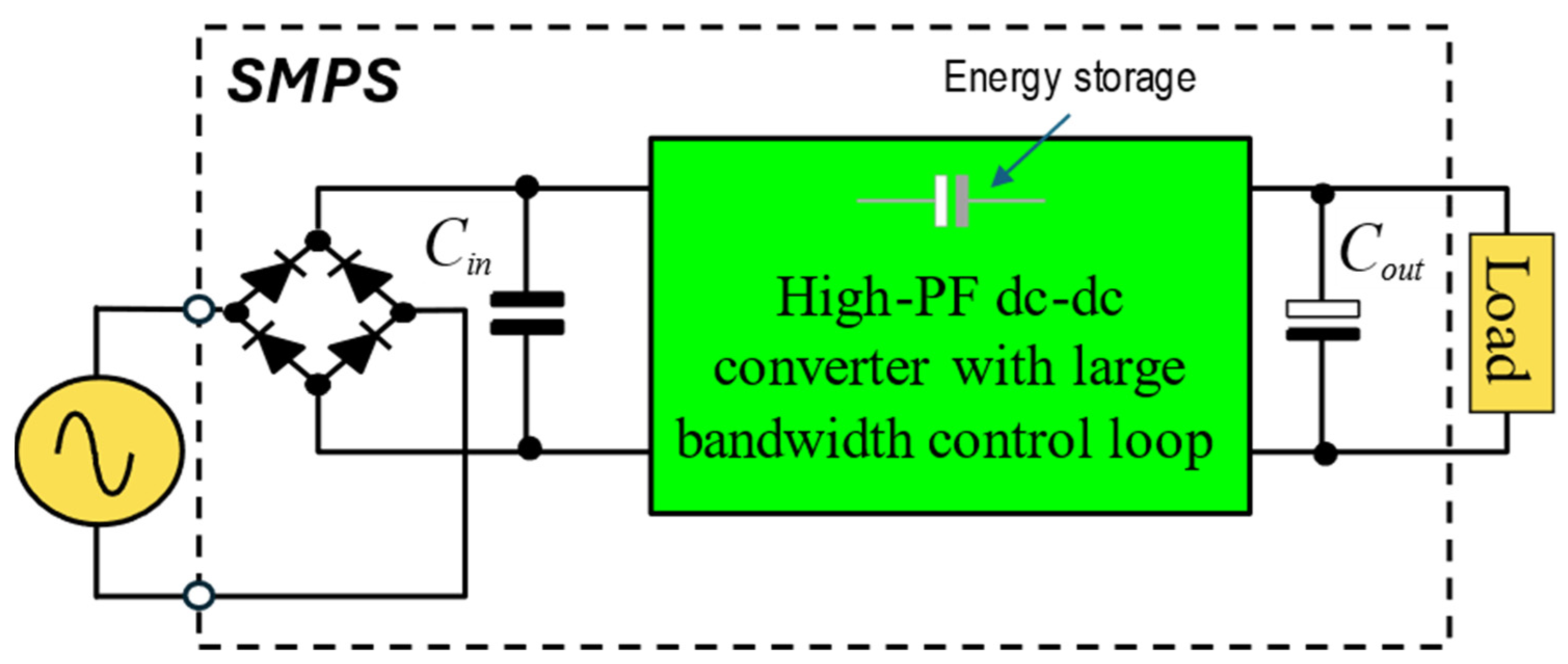
Figure 12.
Single-stage power-factor-corrected SMPS with fast control loop.
Reference
- Adragna, C.; Bianco, A.; Gritti, G.; Sucameli, M. State-of-the-Art Power Factor Correction: An Industry Perspective. Encyclopedia 2024, 4, 1324–1354. [Google Scholar] [CrossRef] [Scilit]
Disclaimer/Publisher’s Note: The statements, opinions and data contained in all publications are solely those of the individual author(s) and contributor(s) and not of MDPI and/or the editor(s). MDPI and/or the editor(s) disclaim responsibility for any injury to people or property resulting from any ideas, methods, instructions or products referred to in the content. |
© 2025 by the authors. Licensee MDPI, Basel, Switzerland. This article is an open access article distributed under the terms and conditions of the Creative Commons Attribution (CC BY) license (https://creativecommons.org/licenses/by/4.0/).