


Abstract
Textile-reinforced concrete (TRC) is an alternative class of mechanical reinforcement for cement composites. The biaxial braided reinforcement structure in composite materials with diverse cross-sectional shapes offers high adaptability, torsional stability, and resistance to damage. In general, 3D textile reinforcements improve the mechanical properties of composites compared to 2D reinforcements. This study aimed to verify reinforcement behavior by comparing multidimensional braided textiles, 2D (one- and two-layer) reinforcements, and 3D reinforcement in composite cementitious boards. Experimental tests were performed to evaluate the effect of textile structures on cementitious composites using four-point bending tests, porosity measurements, and crack patterns. All textiles showed sufficient space between yarns, allowing the matrix (a commercial formulation) to infiltrate and influence the composite mechanical properties. All composites presented ductility behavior. The two layers of 2D textile composites displayed thicker cracks, influenced by shear forces. Three-dimensional textiles exhibited superior values in four-point bending tests for modulus of rupture (7.4 ± 0.5 MPa) and specific energy (5.7 ± 0.3 kJ/m2). No delamination or debonding failure was observed in the boards after the bending tests. The 3D textile structure offers a larger contact area with the cementitious matrix and creates a continuous network, enabling more uniform force distribution in all directions.
1. Introduction
Savings in concrete use constitute an environmental advantage by reducing CO2-equivalent emissions [1]. For this reason, many opportunities and challenges related to raw materials have emerged in the civil construction sector, such as recycled concrete aggregates, filler substitution, CO2 treatment, and even textiles [2]. Textile-reinforced concrete (TRC) is an alternative mechanical reinforcement for cement composites [3,4,5,6,7]. TRC requires less cement cover than steel reinforcement, enabling slender, lightweight products. Since it is focused on prefabrication solutions, precast boards allow savings in the following: (1) concrete consumption (60–85%); (2) embodied energy of building components (cost reduction related to production, transportation, and application); and (3) end-of-life waste (nearly 60%) [8,9].
The mechanical properties of TRC are affected by its design parameters, which are still not well-established [10]. Some studies have addressed issues related to textile reinforcement geometry [11,12,13,14,15,16], fiber-to-matrix bonding performance [17,18,19,20], processing [21], and long-term performance [22,23,24,25].
Current and future trends of research in reinforcements of TRC encompass the following: improving the bond between textile and concrete matrix (profiling of the reinforcement, impregnated textile cured in concrete, or mineral impregnated); improving the drapability of textiles (adapting curved elements, thermoset-impregnated textile, or thermoplastic-impregnated textile); novel manufacturing methods (robot-based manufacturing methods, adaptive molds with pin-type tools, additive manufacturing of concrete, or anisotropic fibers); the integration of additional functions (sensory monitoring or energy harvesting); and increasing sustainability (recycled carbon fibers or the separability of textile concrete) [26].
In this experimental study, to mitigate insufficient bonding between textile reinforcement and the concrete matrix [26,27,28], and due to the matrix’s being unable to penetrate the large yarn cross-section, profiling strategies such as resin impregnation to bind internal filaments (reducing inter-filament friction) [29,30] and surface modification, an additive wrapping with a helix structure may enhance stress transfer from the fibers to the matrix [26,31].
The importance of suitable textile geometry is directly linked to its load-carrying capacity in relative tension to the reinforcement ratio, as the matrix typically fails first and does not directly contribute to the composite strength [10,25]. Many textile structure effects on the matrix can influence mechanical properties. Specimens subjected to mechanical tests often exhibit cracks. These failure modes provide evidence of issues related to the textile, matrix, or interface. These textile-reinforced concrete modes are influenced by various textile effects, as demonstrated by the surfaces of composite specimens (specifically the side areas) after bending tests. They can be categorized as fiber rupture, fiber pullout, debonding, delamination, interlaminar shearing, concrete crushing, and shear [32,33,34]. Additionally, cracks observed on the bottom of the specimen can reveal the efficiency of textile reinforcement, as indicated by crack size, distance, and distribution [35,36].
Non-metallic textiles coated with a polymer improve their stability [34]. They behave like a yarn with multiple layers of filaments, forming a single unified reinforcement in which stress is evenly distributed throughout the yarn [37,38]. The main requirements for impregnated polymer on TRC include changes to Young’s modulus, inner and outer bond behavior, fire resistance, and a protective barrier against chemical attacks of alkalis from cementitious matrix chemical composition [29].
In bidirectional textiles (with yarns in two orthogonal directions), only the fibers parallel to the main longitudinal axis are subjected to tension. In contrast, the remaining spaces between the fiber yarns or the steel surface (tailored surface) allow some mechanical interlock between the reinforcement and the matrix [34]. However, the primary accountability for bonding lies in the textile structure, as the textile surface is relatively flat. Hence, the space between yarns (in fabrics) must be sufficiently large to allow the matrix to penetrate, thereby generating interlocking [4,34,39,40,41].
Recycled fibers (2–6 cm in length) agglomerated into nonwoven textile reinforcements have become an effective means of mitigating the brittleness of unreinforced concrete. However, challenges remain regarding fiber collapse due to alkali-induced mineralization in the cementitious matrix, as well as the presence of voids resulting from water absorption, especially under accelerated aging conditions [42,43]. Another study reported that, in TRC with six layers of nonwoven flax at new age (28 days), bending tests achieved a maximum tensile strength of 7 MPa and a toughness of ≥40 kJ/m2. However, after dry–wet accelerated aging, these properties decayed 48% and 85%, respectively. By partially replacing Portland cement with silica fume (30%), flax’s TRC lost only 20% of its toughness [44].
A biaxial braided structure is formed by intertwining two sets of yarns or two yarn systems running in opposite directions. This kind of reinforcement in composite materials with diverse cross-sectional shapes permits high adaptability, torsional stability, and resistance to damage [45,46]. Compared to traditional yarns, braids can improve impact, tensile, and flexural properties [47]. Fiber-reinforced polymer (FRP) containing grid and chopped polyethylene fiber (2%) can also exhibit multiple cracking behaviors, resulting in an intense interfacial shear stress concentration along FRP reinforcement, and a high ultimate load [48].
Generally, three-dimensional (3D) textile reinforcements for cementitious composites have improved mechanical properties compared to two-dimensional (2D) materials [49,50,51]. Non-crimp 3D orthogonal weaving processes and technologies using automatic machines can produce layers of yarns (in the “x” or “y” direction), stitched in the “z” direction, which exhibit low waviness [52,53]. On the other hand, these machineries still have limited availability. Some studies have discussed 3D TRC, including its production using different technologies, such as warp knitting (mesh), employed initially for sporting applications [50,51,52], or fabric hand-layup sewing [15,21,54,55].
This study aimed to create 2D and 3D textile structures using sisal/PET braided yarn coated with epoxy resin. These textile structures were then used to assess the impact of multidimensional reinforcements on cementitious board composites. The evaluation involved mechanical four-point bending tests, physical tests, and crack pattern analysis. In this study, a commonly formulated commercial mortar was used as a matrix. The primary focus was to investigate the specific effect of textile reinforcement, exploring its geometry, load-bearing capacity, and failure modes.
2. Materials and Methods
2.1. Materials
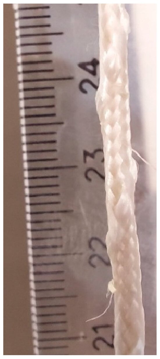
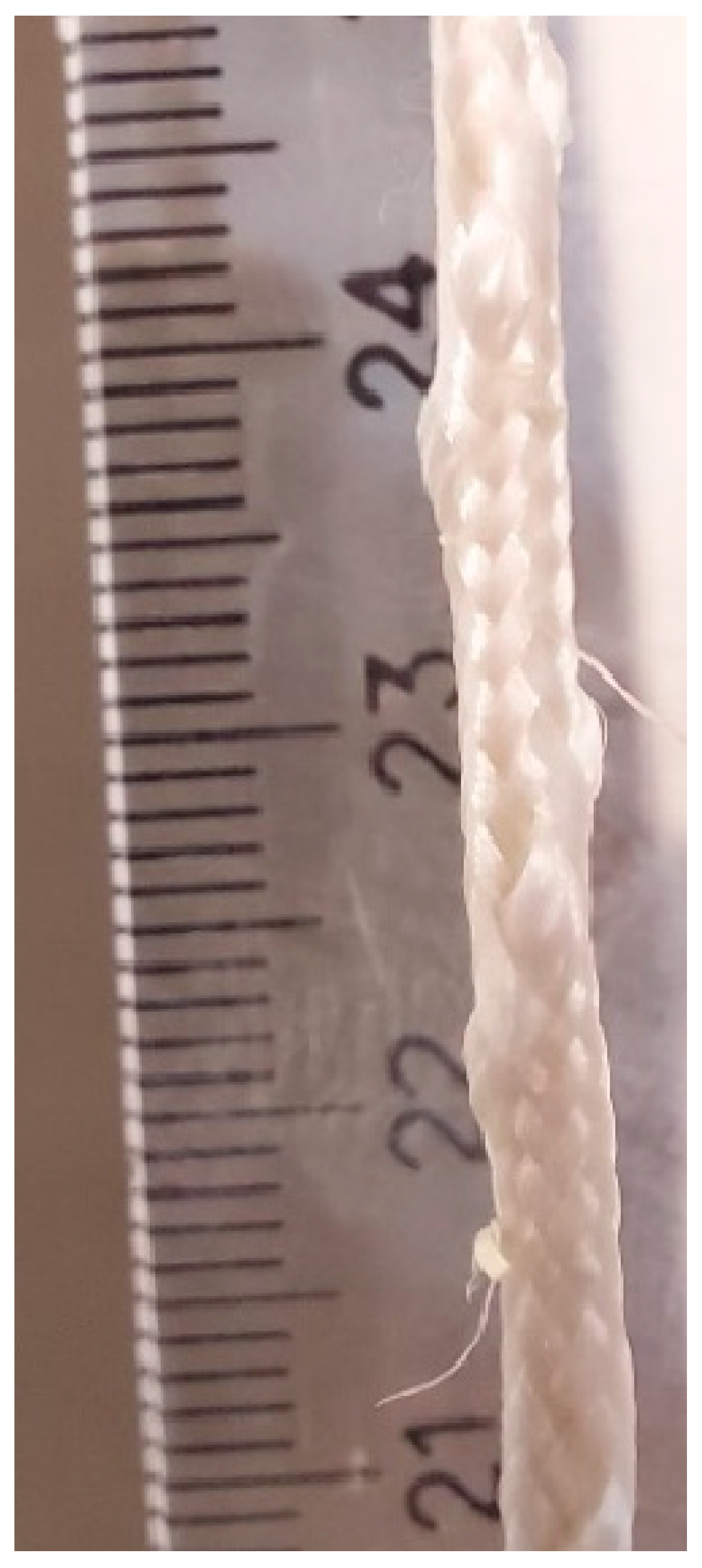
Textile reinforcement consists of a sisal/PET braided yarn (Figure 1), which was previously developed, made by 15 external single polyester HT yarns (45 Tex) and one thicker binder yarn to enhance bonding between textile and matrix [56], evolving a sisal core (1100 Tex, Santanders, China). The sewing black line used to make 3D fabric was polyester (20/3 Ne, Petic, Valfios, Portugal). The coating is a partly (37%) natural source, a green epoxy coating (SR Green Cast 160 and SD7160 in a 100/42 (w/w) ratio, Sincomin, Pluguffan, France), with the following properties: a module of rupture of 2150 MPa, a maximum strength of 38 MPa, and an elongation at break of 15% (data provided by the supplier). A commercial mortar (AAM10, Cimpor, Alhandra, Portugal) was applied as a matrix. It is based on Portland cement (CEM II/A-L 42,5 R), limestone filler, and hydraulic lime (HL 5), with the main component being a blend of Portland cement/limestone filler, meeting the manufacturer’s specification: compression ≥ 10 MPa (the compression test is described in Section 2.2.2). Its average density is 1.5 g/cm3 with an average particle diameter of 0.8 mm (80% between 0.002 and 1.5 mm and ≤3 mm). It was carried out with a particle size distribution analyzer with a laser diffraction system (Partica LA-950-V2, Horiba, Kyoto, Japan).
Figure 1.
Sisal/PET braided yarn structure, sisal yarn in the core and 15 external single polyester plus one thicker binder yarn to improve bonding textile–matrix.
The adhesion of epoxy-coated sisal/PET braided yarn and mortar was previously measured by a single-sided pullout test [57,58]. Slippage samples (65 mm) presented an average maximum load of 471 ± 29 N (6%) [31]. The remarkable effect of this material was toughness, with high values observed. The force up to the initial bonding was 342 N.mm (CoV = 21%), and until the peak load was 2100 N.mm (CoV = 35%), comparable to carbon, glass, or steel (2224, 1588, and 2772 N/mm, respectively) [59,60].
2.2. Matrix Characterization
2.2.1. Slump Test
The Slump test-BS EN 12350-2 uses a reference value of 170 mm to determine consistency. The test involves a mold measuring 60 mm in height and tapering from a 100 mm base to a 70 mm top diameter. Two layers are formed: the first is filled halfway and subjected to 10 taps, followed by the second layer, which is also subjected to 10 taps. After 15 s, the mold is removed, and a mechanical jolt is applied 15 times at 1 per second, followed by immediate diameter measurement in two directions [61].
2.2.2. Compression
To verify the supplier’s specifications, the commercial mortar was characterized in accordance with masonry application standards (BS EN 1015-11, 2019) [62]. Compressive strength tests were conducted using a Universal Testing Machine (LR50kPlus, LLOYD Instruments, Ametek Company, Largo, FL, USA) equipped with a 50 kN load cell at a compression rate of 0.01 mm/s. Three specimens, each approximately 40 × 40 × 160 mm, were cast in iron molds and vibrated to eliminate air/voids. After 24 h, the samples were demolded, sealed in plastic bags, and thermally cured for 7 days at 65 °C. A compression test previously validated the thermal curing method using the same mortar. A comparison with the curing method, which involved curing for 28 days at 20 °C and 65% humidity, yielded similar results in the compression and three-point flexural tests, suggesting that the methods are interchangeable [31].
2.2.3. X-Ray Diffraction Analysis
X-ray diffraction (XRD) was applied to determine the hydration products formed in the matrix employing an X-ray diffractometer Rigaku Miniflex 600, Tokyo, Japan, with CuKα radiation generated at a voltage of 40 kV and a current of 30 mA, which was used to scan the samples between 5° and 75° 2θ at 2°/min.
2.3. Textile Properties
Braided yarns, manually coated with green epoxy (SR Green Cast 160 and SD7160 in a 100/42 (w/w) ratio, Sincomin, France), were tested according to the adapted standard ISO 2062 for the determination of single-end breaking force and elongation at the break using a constant rate of extension [63].
Textile 2D and 3D Reinforcement Structures
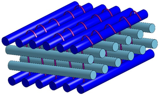
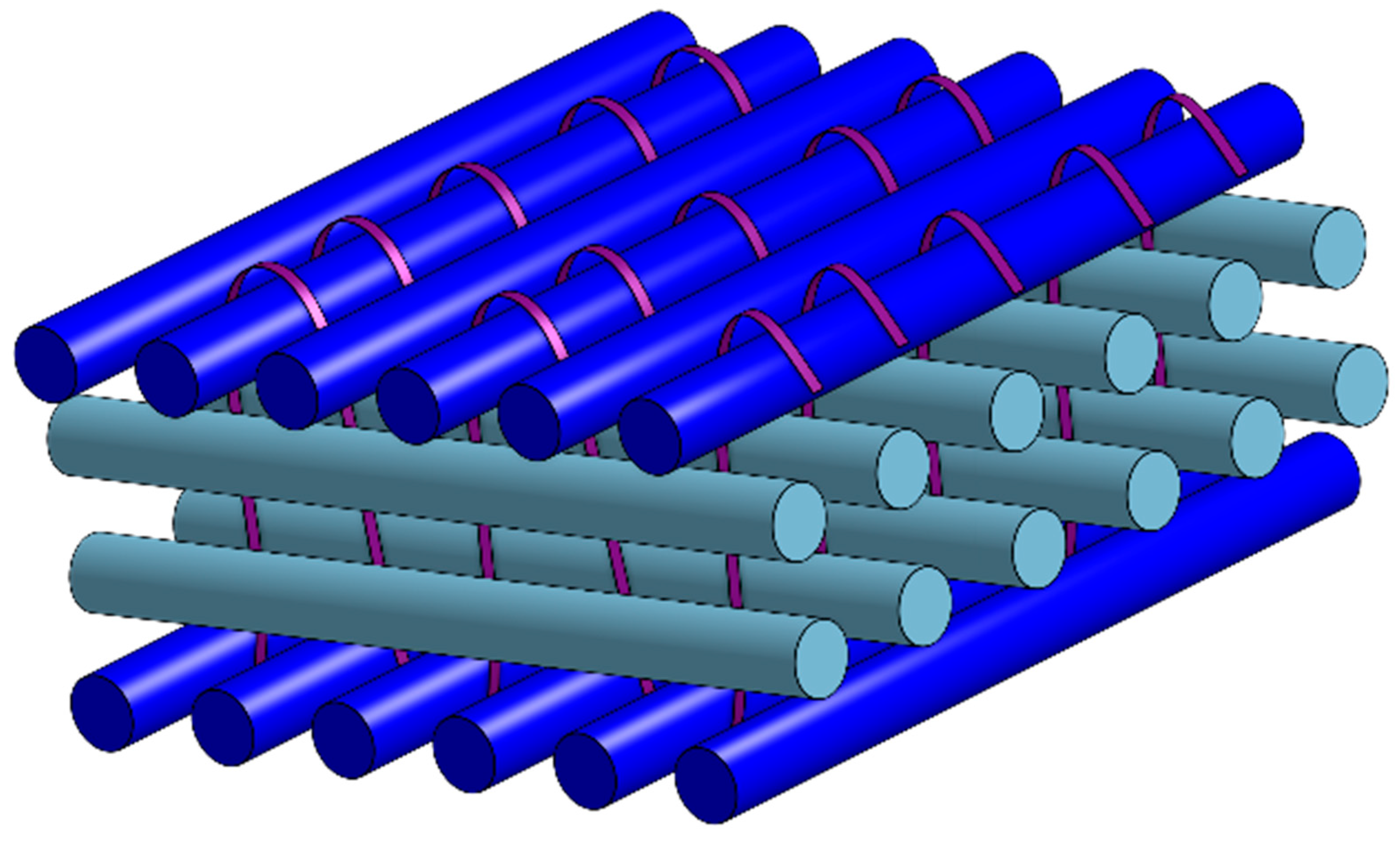
Generally, the optimal distance between yarns is 8–30 mm [34]. For thicker yarns, such as epoxy-impregnated carbon were all categorized as heavy tow (>2400 Tex) textiles, with a diameter of 8–17 mm and a distance between rolls of 21–38 mm [30]. Another study used a carbon/PES braided textile upper with 3200 Tex (diameter > 5 mm) and a spacing of 25 mm [64], or PVA filaments with 1650 Tex and a grid of 12 × 9 mm. For the definition of fabric structure and yarn spacing, a distance of 10 mm between rolls in the mold was stipulated, despite a smaller diameter of 2.7 ± 0.2 mm and a high value of 2580 Tex [40,63]. The fabric structure is crucial to avoid high-tension points in plain woven textiles; hence, the new fabric is based on the Malimo structure, in which yarns overlap without crimping, thereby preventing premature failure (Figure 2) [65].
Figure 2.
Schematic design of Malimo’s structure of three-dimensional fabric, where yarns are propped up one over the other and joined by sewing and epoxy resin.
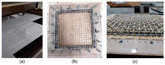
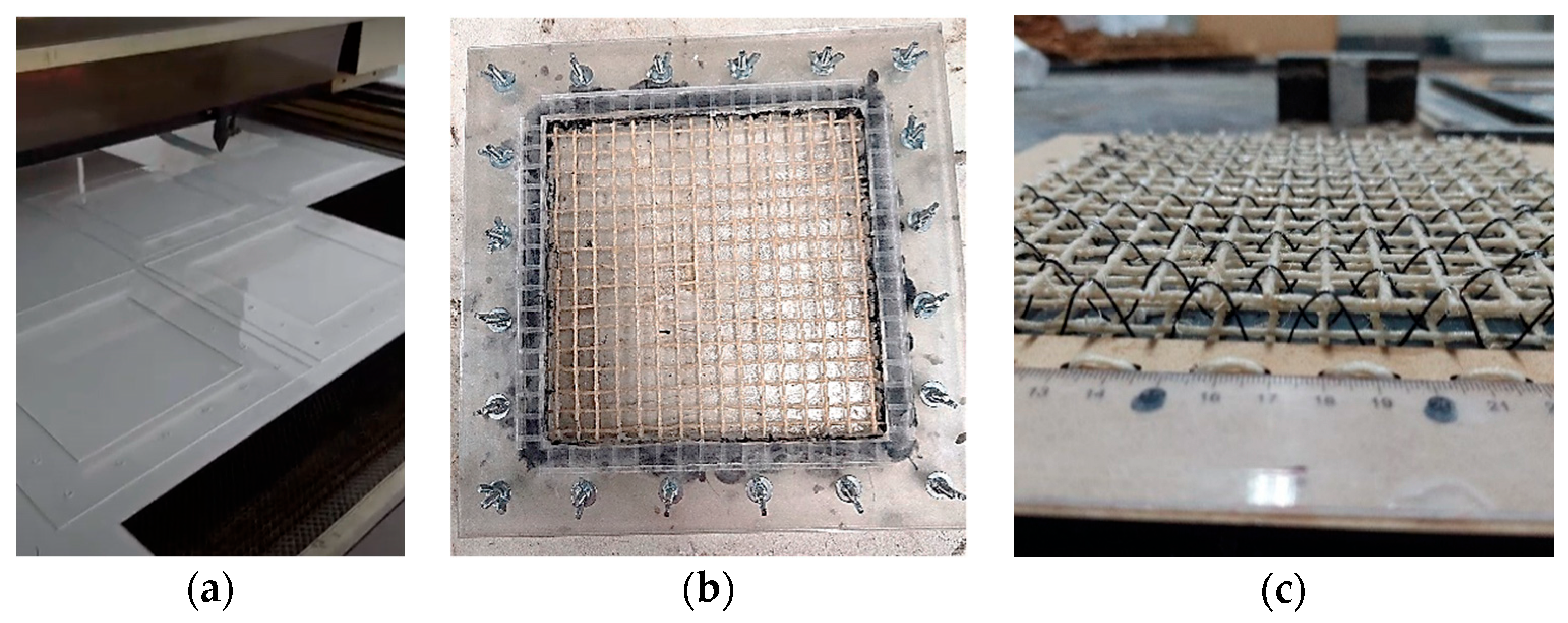
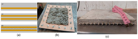
Two-dimensional (2D) and three-dimensional (3D) fabrics were constructed, according to previous studies [21,55], with two layers of 2D fabrics sewn together using a PET black line in an interlocked orthogonal arrangement, to demonstrate the function of the stitching and the effect it has when fibers are oriented in the z-direction in the reinforcement. The textiles and casting molds were designed in AutoCAD 2023 (Autodesk Inc., San Francisco, CA, USA) and prototyped in extruded acrylic using laser cutting (Figure 3a). The mold allowed the yarns to be placed and stretched uniformly, maintaining consistent spacing and positioning the textile along the composite board (Figure 3b,c and Figure 4c).
Figure 3.
Textile 2D and 3D reinforcement construction: (a) acrylic laser cutting for textile and casting molding; (b) 2D textile development into casting molding; and (c) 3D textile structure.
Figure 4.
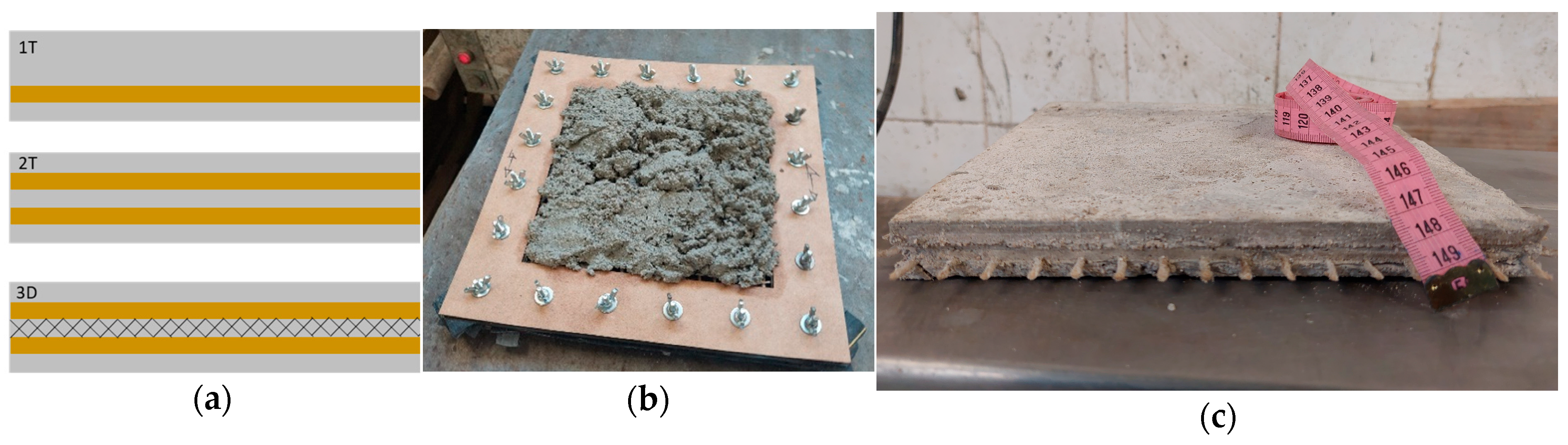
Composite processing: (a) schematic design of composite reinforced by 1T (one layer of 2D textile) (above), 2T (two layers of 2D textile) (middle), and 3D (one 3D textile) (below), (b) composite molding-insertion of mortar into the mold with textile material inside, and (c) 1T board after curing.
After construction, all samples were coated with a bicomponent epoxy resin (Cast 160 and SD7170SR) at a 100/42 (w/w) ratio. The application process involved manually brushing the resin onto the braided textiles. The samples were then allowed to dry for 48 h at room temperature, followed by curing in an oven at 60 °C for 16 h [66]. The final distance between the yarns after coating was 8 mm × 8 mm. This spacing provides adequate openings for matrix interlocking, which can help enhance the ultimate tensile strength [40,67].
2.4. Composite Processing
Two boards of each type of composite were made in three configurations of TRC (Figure 4a): 1T (one layer of 2D textile, Figure 4a above and Figure 4c), 2T (two layers of 2D textile) (Figure 4a middle), and 3D (one 3D textile) (Figure 4a below). Textile structures were placed in the mold along the edge, with a 5 mm height separation between layers from the bottom, except for the 1T configuration, which had the most excellent mortar height above the textile to ensure all samples had a total height of 22 mm. All mold pieces were sealed with rubber to prevent leakage. To create the composite boards, 208 g of water (determined by the slump test) was mixed with 1600 g of mortar. The matrix was poured (Figure 4b) into each of three casting molds (200 × 200 × 22 mm) with the positioned textiles, and the molds were vibrated for 2 min in each mortar layer to remove air/voids. Two additional boards of the same size (22 mm) were molded without reinforcement for comparison. Each TRC board was then cut into four specimens (approximately 200 × 40 × 22 mm) using a water-cooled diamond saw for mechanical and physical testing.
2.5. Composite Characterization
2.5.1. Physical Tests
Water absorption (WA), bulk density (BD), and apparent void volume (AVV) of fabric–cement composites were determined according to ASTM C-948-81 [68] and calculated using Equations (1)–(3) [68].
where Mi is the mass immersed in water; Msat is the mass of the saturated specimen with a dried surface; and Mdry is the total dry mass of the specimen after 24 h in an oven at 105 °C.
2.5.2. Four-Point Bending Test
A four-point bending test was performed to evaluate the mechanical performance of the fiber–cement textile reinforcement. The test was carried out on a servo-hydraulic testing system adapted for four-point bending tests, employing specimens (160 × 40 × 22 mm) with a minor span of 45 mm and a significant span of 135 mm, at a loading rate of 1.5 mm/min. A universal testing machine with a 25 kN load cell, a 6 mm range, and a 2 μm sensitivity LVDT (Linear Variable Differential Transformer) was used. The modulus of rupture (MOR), the limit of proportionality (LOP), the modulus of elasticity (MOE), and specific energy (SE) were calculated, respectively, following Equations (4)–(7) [69,70]:
where Pmax is the maximum load (N); Linf is the major span between the supports (mm); Lsup is the minor span between the two loading points (mm); w and h are the composite width (mm) and height (mm), respectively; Plop is the load at the upper point of the linear portion of the load-deflection curve (N); P is the load (N); and δ is the deformation (mm) [71,72].
3. Results and Discussion
3.1. Matrix Characterization
To achieve the diameter of 170 mm at the slump test, the relation of water: matrix was 1:7.7 (w/w). The mortar compression test after 7 days of thermal curing (11 ± 1 MPa, C.V. of 4.8%) confirmed the supplier’s specified value (≥10 MPa).
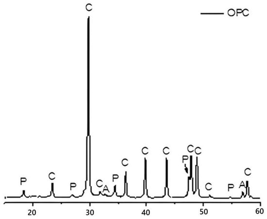
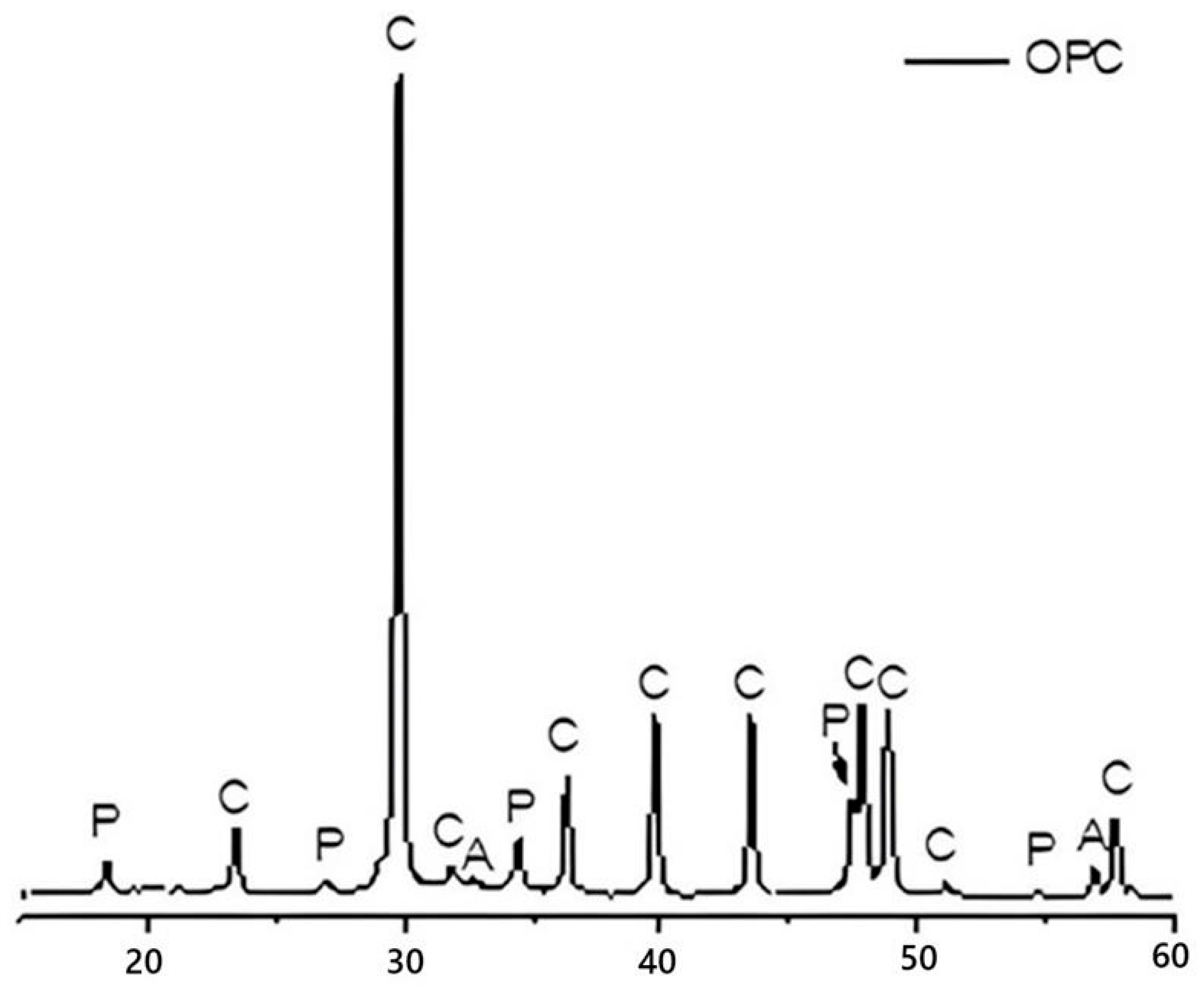
The inorganic matrix phases by X-ray diffraction (XRD) analysis were present in the cementitious composites, the diffraction peaks corresponding to Portlandite (Ca(OH)2) (ICSD-15471), Calcite (CaCO3) used as filler in the inorganic binder formulation (ICSD-40052), and Alite (ICSD–64759) (Figure 5). The presence of Portlandite peaks is attributed to the hydration reactions of Portland cement, leading to the formation of calcium hydroxide (Ca(OH)2). Furthermore, the XRD pattern also reveals residual Alite phases even after exposure to water. This observation suggests that some Alite crystals were incompletely hydrated during paste mixing. Consequently, this may indicate a potential delay in the development of mechanical strength following hydration. The formation of C-S-H (Calcium Silicate Hydrate) is the primary mechanism for strength gain in cementitious materials, and its formation is dependent on complete Alite hydration [73]. Moreover, the intensity of the Calcite diffraction peaks suggests a high degree of atomic order within the filler material. This highly ordered structure contributes to Calcite’s low reactivity kinetics when interacting with Portland cement and water in the composite matrix.
Figure 5.
XRD pattern of the inorganic binder used as the matrix in the mortar production. Portlandite (P), Calcite (C), and Alite (A) peaks.
3.2. Textile Properties
The mechanical properties of epoxy-coated sisal/PET braided yarn are presented in Table 1.
Table 1.
Physical and mechanical properties of coated sisal/PET braided textile: count number (Tex), thickness (mm), tensile strength (N and MPa), strain to failure (%), Young’s modulus (N/Tex) (values expressed as average, standard deviation, and coefficient of variation). Source: the authors.
According to the Table 1 values, the epoxy-coated sisal/PET braided yarn presents a relatively thicker diameter (average of 2.7 mm), higher elongation at failure (12 ± 4%), and superior strength capacity (492 ± 52 N) than traditional textile yarns (Table 1, sisal or PET). This is due to its braided structure, which provides a higher load-bearing capacity for this method, analogous to rope production [46,47].
3.3. Composite Characterization
3.3.1. Physical Tests
The physical tests of composite specimens are presented in Table 2.
Table 2.
Physical tests of water absorption (%w/w), bulk density (g/cm3), apparent void volume (%v/v), mortar (M), 1T (1 layer of 2D textile), 2T (2 layers of 2D textile), and 3D (1 layer of 3D textile) (values expressed as average, standard deviation, and coefficient of variation). Source: the authors.
The results in Table 2 are similar for water absorption, bulk density, and porosity. The low coefficients of variation (ranging from 1 to 4%) are also remarkable. This indicates the uniform composition of the specimens, which employed the same mortar and coated braided textile. This uniformity is essential, as it demonstrates the accuracy of sample preparation and the practical application of the coating.
In another study reported in the literature, polypropylene/flax braided yarn presented a higher maximum load (172 N) and tenacity (8 cN/Tex) than co-wrapped yarn (102 N and 7 cN/Tex, respectively) [74]. With the braided yarn in the TRC with 15 filaments, one braided relief of polyester externally, and glass in the core, it formed a braided yarn to control damage to the masonry fillings, and cracking of the mortar was reduced, showing an improvement in the lateral drift resistance of 3% and an increase of 51% in energy dissipation capacity [75]. At the core, basalt, AR-glass, carbon roving, and PP were compared with each other to build a new braided yarn, with three distinct core raw materials tested in four-point bending; flexural strength and toughness increased by approximately 19% and 143%, respectively [14].
3.3.2. Four-Point Bending Test Analysis
Typical curve—effect of sisal/PET braided textile.
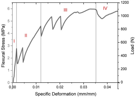
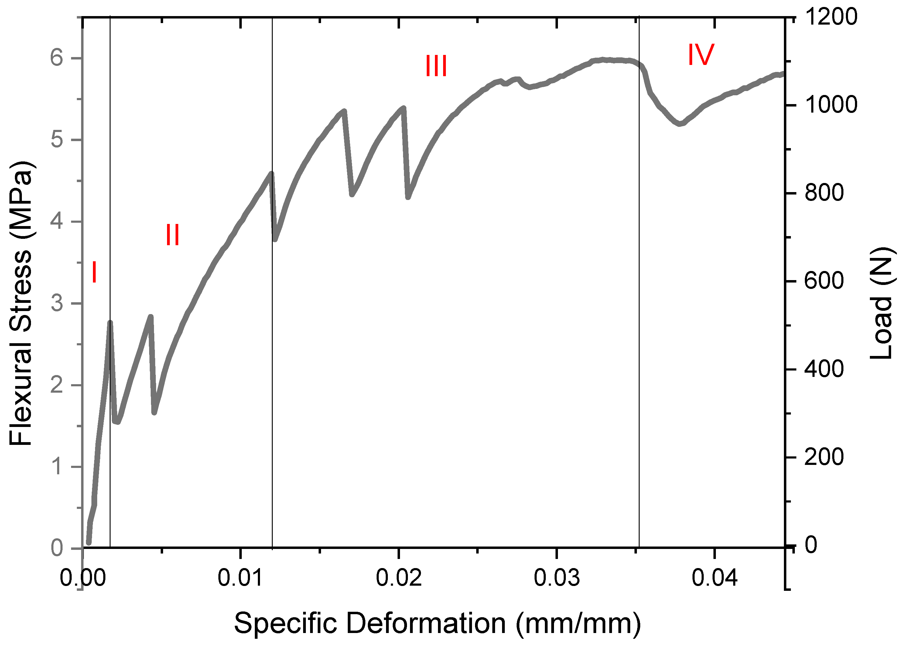
The typical bending stress curve shows the sisal/PET braid textile reinforcement behavior of a 1T (one layer of 2D textile) composite structure, as shown in Figure 6. In TRC materials, Zone I is the elastic, or pre-cracking, zone. It is driven by the cementitious matrix, where bending loads act directly on it and, therefore, it reaches its ultimate strength, which in this graph is 2.7 MPa. Brittle and rigid matrices tend to fail suddenly at this stage. In Zone II, from the start of the curve, the first and second cracks occurred at the bottom of the matrix; after the cracks, the flexural stress dropped suddenly, indicating matrix behavior. However, after the crack event, the textile reinforcement acts, allowing the composite to strain-harden due to frictional forces, pull-out, and yarn elongation. Its stiffness depends on reinforcement properties, fiber volume, and the matrix–fiber bond. [76,77]. The strain-hardening event continues as the load is continuously applied, surpassing the drop in resistance. In Zone III, where the existing cracks advance until the ultimate stress is reached, the observed flexural stress values in this region are related to the yarn’s strength and strain capacity under the applied loads [78]. The last zone, Zone IV, is related to failure, or debonding. In this stage, the textile also acts after the post-peak (maximum load), and the existing cracks widen until the fiber’s tensile strength is reached, at which point the composite completely fails [79]. It is the strain-softening of the composite when the reinforcement no longer supports the applied load. It is not explicit in the graph, because the test ends before complete failure, and the LVDT had a limit of extension (up to 6 mm), not reaching the failure or debonding moment.
Figure 6.
Typical mechanical four-point bending test behavior response of sisal/PET braided TR-1T (one layer of 2D textile) composite structure, including the main behavioral stages (I–IV): I (elastic), II (onset of cracking), III (the ultimate stress), and IV (failure).
3.3.3. Effect of Multidimensional Reinforcement
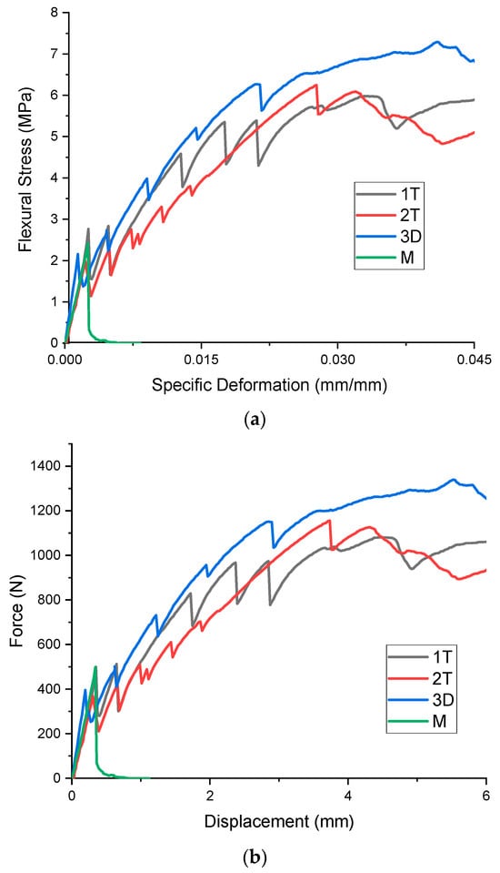
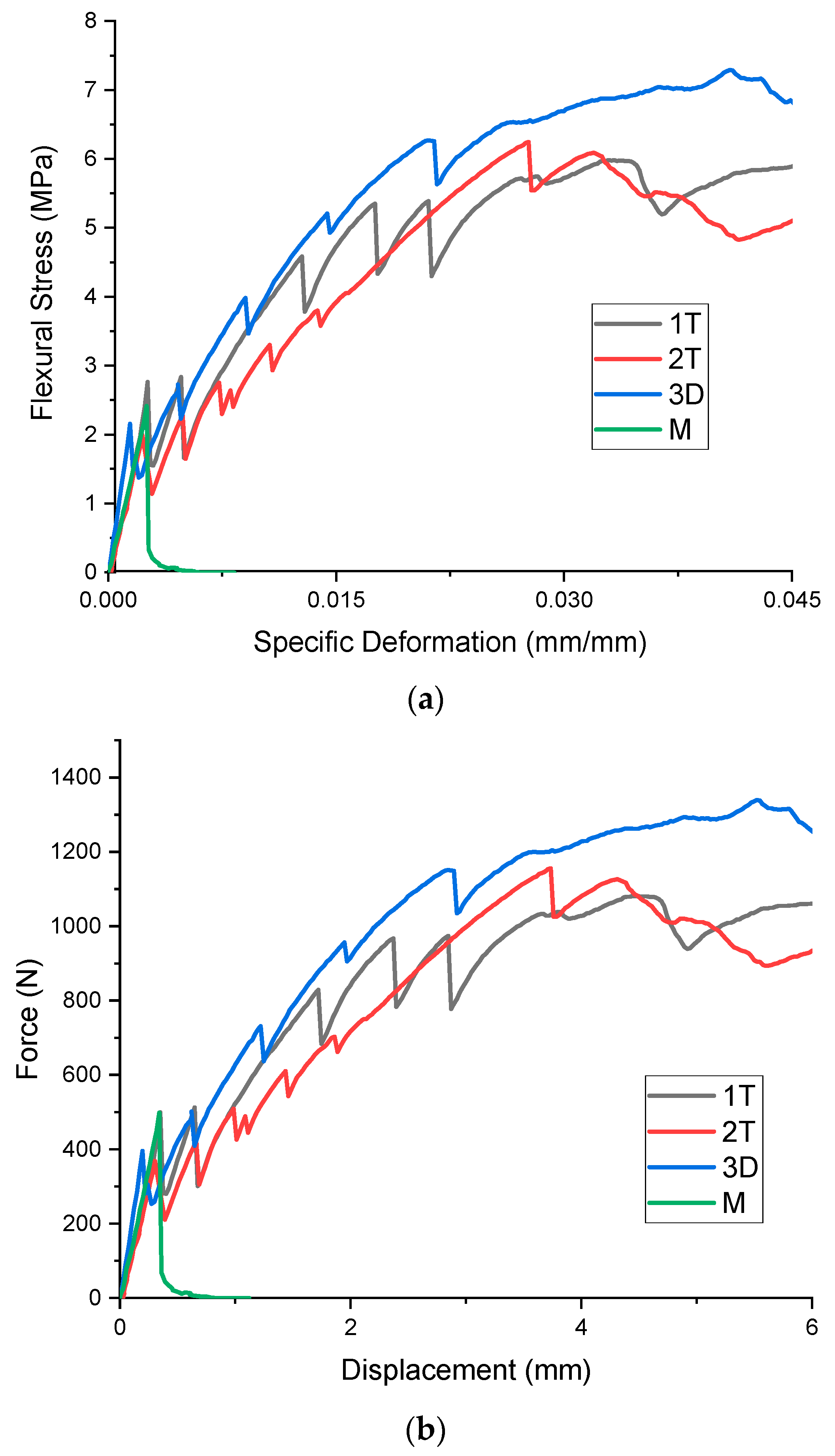
Regarding the multidimensional TRC effect, samples were evaluated using flexural stress-specific deformation curves. In Figure 7, 1T (1 layer of 2D textile) is expressed by the black line, 2T (2 layers of 2D textile) by the red line, 3D (1 layer of 3D textile) by the blue line, and M, in green, representing only the mortar. These composite behaviors (as shown in Figure 7, where average values are represented) exhibit a trend similar to the typical bending stress curve (Figure 6). Zone I is identified as the pre-cracking zone, influenced by the matrix’s modulus of elasticity [80]. As noted in Table 3, this similarity in the data on the matrix’s elasticity was confirmed by ANOVA and the Tukey test. However, high standard deviations were observed, with the results being governed by the properties of the mortar, which also exhibited considerable variation in its elastic modulus values, probably influenced by the high amount of limestone filler. As expected, the fragile mortar matrix fails at the first crack without reinforcement (Figure 7, green line).
Figure 7.
Curves representing average (b) values of force (N) vs. displacement (mm), (a) values of flexural stress (MPa) vs. specific deformation (mm), of sisal/PET TRC composites after 7 days of thermal cure: 1T (1 layer of 2D textile) (black line), 2T (2 layers of 2D textile) (red line), 3D (1 layer of 3D textile) (blue line), and M representing only mortar (green line).
Table 3.
Mechanical properties of four-point bending tests of the composites’ modulus of elasticity (MPa), limit of proportionality (MPa), modulus of rupture (MPa), and specific energy (kJ/m2): mortar (M); 1T (1 layer of 2D textile); 2T (2 layers of 2D textile); and 3D (1 layer of 3D textile) (values expressed as average, standard deviation, and coefficient of variation). Results were statistically analyzed using a completely randomized design to compare means, and the Tukey test was used at the 0.05 significance level.
In Zone II, all composites with multidimensional reinforcements (1T, 2T, and 3D) showed a similar trend: cracks developed until the reinforcement fabric began to act, at which point the flexural stress capacity increased. Among the composites, the 2T curve exhibited lower strain-hardening than the 1T and 3D curves, likely due to its lower material stiffness [81]. Meanwhile, 3D featured multiple coated sewing lines, and 1T had a thicker matrix.
Zone III marked the stage at which cracks began to propagate through the composite, and the flexural stress reached its maximum. The 3D reinforcement showed the highest flexural stress (7.4 ± 0.5 MPa), although 1T and 2T reached similar MOR (6.2 ± 0.6 MPa and 5.6 ± 1.0 MPa, respectively), as confirmed by ANOVA and Tukey analysis. Finally, in Zone IV, following the modulus of rupture, the flexural stress for 1T and 3D samples remained stable on a plateau, despite varying stress levels, whereas 2T experienced a curve decline (Figure 7a).
Generally, after the initial crack, the textile begins to work as a reinforcement. Both 2D and 3D textiles provide similar reinforcement (Figure 7a). However, the 3D textile is 22% higher in flexural stress (modulus of rupture of 7.4 ± 0.5 MPa—Table 2) and 20% higher in specific energy (5.7 ± 0.3 kJ/m2—Table 2) compared to the 1T sample. However, this increase was not proportional. Despite the 3D textile containing at least twice as many yarns, the flexural stress did not double.
TRCs were compared with polypropylene fiber additions (0.7 and 1.3%) using a fly ash matrix [53] in a four-point bending test (28 days, thickness of 15 mm). Even though stiffer 3D AR-glass textiles (mesh size 22.5 × 22.5 mm), connected through polyester yarn and treated with an SBR-coating, was used, 3D, 3D-0.7%, and 3D-1.3% presented the first crack load (164 ± 10 N, 148 ± 6 N, and 143 ± 6 N) and an ultimate load (405 ± 40 N, 472 ± 38 N, 556 ± 26 N) at around 40 mm (displacement), respectively. This indicates that, even if the first crack load and ultimate load of 3D were lower than those in this study (305 N and 1339 N, Figure 7b), the displacement was higher, leading to an increase in specific energy; in addition, the dispersed fiber assists in increasing the ultimate load. In another study, matrix with slag with three or five multilayers of commercial 2D kenaf fabrics (3 × 3 mm) TRC were compared by four- point bending test (28 days): the first crack load (1058 ± 30 N, 1109 ± 12 N, and 1215 ± 310 N) and ultimate load (150 ± 30 N, and 368 ± 10 N) at around 2 mm presented limited tenacity and an abrupt drop of load [82].
One contributing factor is the textile’s position on the board. In the 1T specimens, the textile was positioned 5 mm from the bottom. This position is considered optimal for action because the bottom is in the tensile zone. In contrast, the 3D textile was positioned in the middle of the board, with reinforcement distributed across the bottom (tensile zone), middle (neutral zone), and top (compression zone), where the region between the bottom and neutral line (middle) provides the most significant influence on bending resistance to stress.
This effect of textile position on flexural strength was based on this study, that the maximum flexural strength of 24 MPa was achieved with the HY carbon sample reinforced at 3 mm (left image of Figure 7). In this sample, the strength was four times greater than without reinforcement. In contrast, reinforcement at 5 and 10 mm increased strength by four- and three-fold, respectively [14].
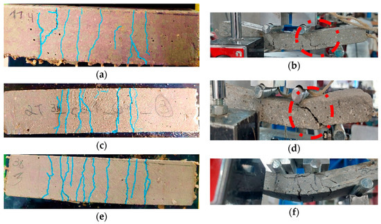
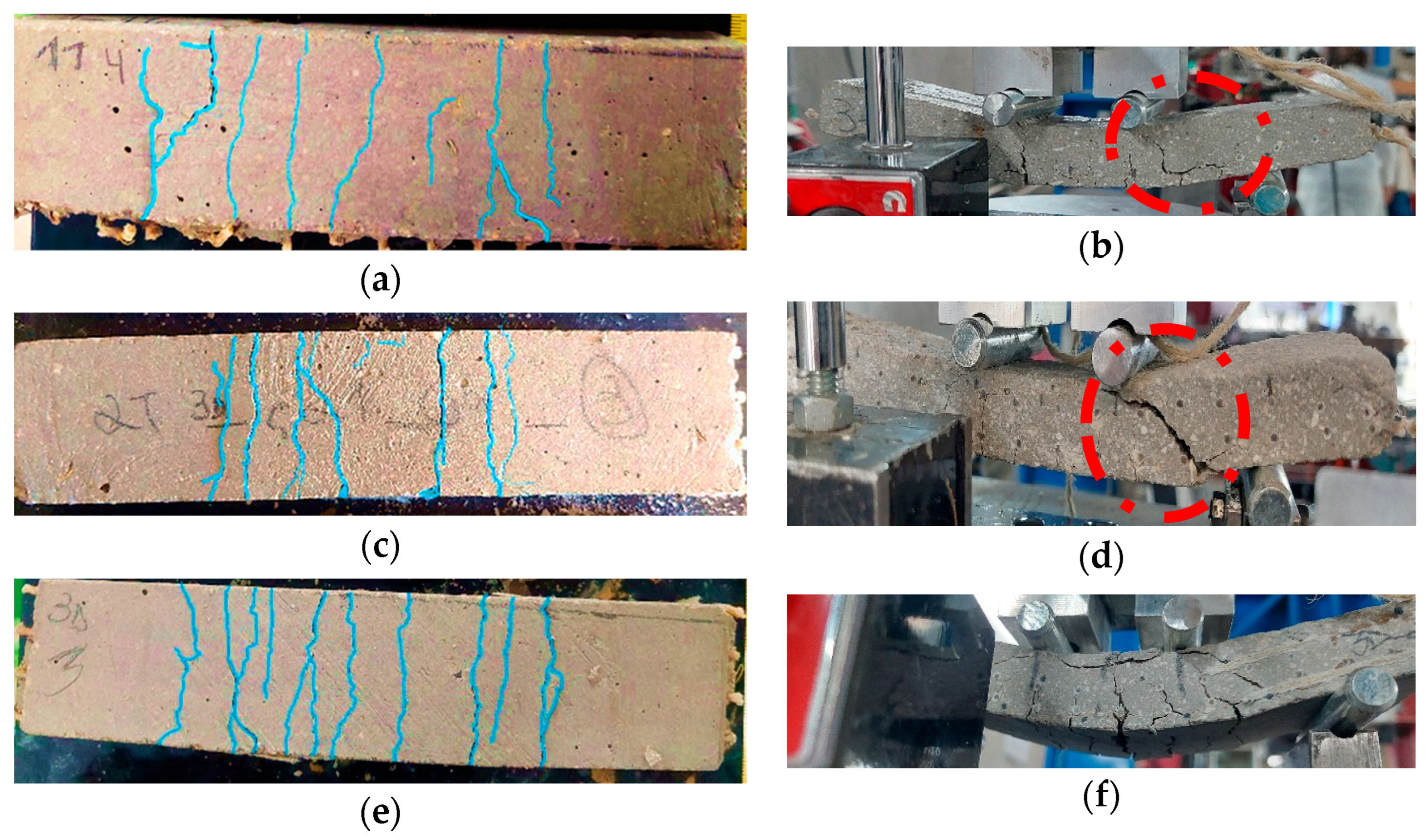
Additionally, the decrease in 2T’s properties may be attributed to the absence of interlayer connections. Evidence supports this property reduction in the crack patterns shown in Figure 8c,d. The presence of more prominent and thicker holes, indicative of shear cracks (perpendicular to the applied force, as shown in Figure 9a) [34,83,84], is evident above the 2D textile layer, particularly in the 2T specimen (Figure 8d). This observation can be linked to the reduction in properties, noticeable towards the end of the test when the fibers are actively functioning as reinforcement. To mitigate the reduction in bending capacity caused by two fabric layers, it is common to add bond anchors [32]. Although the 1T TRC also exhibited similar failure patterns, these were thinner (Figure 8b). Such cracks are commonly observed in the excessive flexural strengthening of TRC [21,34].
Figure 8.
Comparison of crack patterns on TRC with multidimensional reinforcement. 1T (1 layer of 2D textile) (a) bottom view, (b) side view; 2T (2 layers of 2D textile): (c) bottom view, (d) side view; 3D (1 layer of 3D textile): (e) bottom view, (f) side view.
Figure 9.
Schematic of failure modes of TRC: (a) shear failure, (b) concrete crushing. Adapt from Ref. [34].
Comparing crack behavior among multidimensional samples, the 3D samples exhibited well-distributed cracks scattered across the boards (Figure 8a) and a greater number of cracks than the 1T samples (Figure 8e). In contrast, the 2T samples showed a more concentrated pattern of cracks in the center (Figure 8c). The cracks in the 3D samples, observed on the side of the board during the four-point bending test, were also well-distributed and did not exhibit shear cracks. Instead, concrete crushing was observed (in the middle of Figure 8, similar to Figure 9b). Concrete crushing is typically associated with preventing debonding propagation [34].
It is important to highlight that the primary failure modes of TRC are typically caused by textile slippage, resulting from the separation of the matrix and textile due to incomplete bonding, slippage, or delamination [85]. This issue is particularly pronounced in the 1T configuration samples, where the textile is positioned near the bottom of the board. Inadequate bonding in the TRC can lead to additional failures such as textile rupture, textile pullout, debonding, interlaminar shearing, or peeling of the concrete [32,34]. However, in the present study, none of the evaluated composites exhibited these failure modes.
3.3.4. Three-Dimensional Braided Textile Reinforcement Effect
Three-dimensional TRC identified two adverse effects of their reinforcement compared to 2D TRC. First, stiffness increases but has no significant consequence on the flexural response, and second, there is a higher ultimate load in the flexural test. Four different layouts of composites with two planar layers and four other fabrics with the same planar connected through transversal polyester (0.3 mm) were compared. All textiles were SBR-coated, and the raw materials used were two different glass fabrics and another carbon fabric. The flexural response showed a post-cracking stiffness increase of 21% to 28% compared to their 2D equivalents, but this increase was not observed in the tensile experimental response [81].
On the other hand, another report comparing almost the same carbon structure (1600 Tex and distance between yarns) of two layers of 2D and 3D fabrics, only joined by carbon 1600 Tex, all of them coated by epoxy resin, applied to composite beams with 100 × 100 × 400 mm dimensions, showed that the 3D structure obtained better mechanical properties in the four-point bending test (ultimate load of 34 ± 3 kN and 26 ± 2 kN), but similar modulus of elasticity and elongation [21].
Three-dimensional collaborative textile-reinforced self-stressing concrete (TRSSC) was calculated using a finite element model based on elastic mechanics to simulate cracking load and deflection. The theoretical calculations aligned with their experimental results. To obtain experimental data, 3D TRSSC and 2D TRSSC were subjected to a four-point bending test, and the effects of different textile forms on the bending mechanical properties of the specimens were investigated. Collaborative fiber could effectively improve the working performance of plane textiles by increasing 3D self-stress and coordinating the deformation of layered textiles. The stress of the collaborative fiber could be obtained from geometric analysis of the textile’s deformation, since the specimen was already in large deformation when it was damaged. Then, the improvement of the ultimate load of 3D TRSSC relative to 2D TRSSC could be analyzed. According to this report, the addition of the collaborative fiber significantly ameliorated the bending performance of the beam. Compared to the 2D TRSSC, the cracking load increased by 40%, the cracking deflection increased by 35%, the cracking toughness index increased by 93%, and the ultimate load increased by 34%. The mediation of the collaborative fiber on the internal force of textiles was determined by analyzing the geometric relationship of the collaborative fiber’s deformation. It was calculated that the addition of collaborative fiber increased the ultimate bending moment of the 3D collaborative textile by 45% compared with that of the 2D textile [21].
Cementitious composites with 3D textile structures exhibit superior performance compared to those reinforced with other types of reinforcements, due to the unique properties of the three-dimensional structure. In this manner, as evidenced by the results of the present study, the use of 3D textiles also positively affects the mechanical properties of the TRC.
The 3D textile structure has a higher surface area in contact with the cementitious matrix than other reinforcement types, forming a continuous network throughout the composite and allowing stresses to be distributed more evenly in all directions. This enhances load distribution and improves crack resistance. The network can bridge cracks, preventing their growth and leading to a more ductile failure mode. This contrasts with traditional reinforcements, where cracks may propagate more easily in directions not aligned with the reinforcement. The 3D textile structure can absorb and dissipate energy, helping increase the toughness and ductility of the composite, making it more resilient under loading. Moreover, it has a greater surface area in contact with the cementitious matrix than other reinforcement types. This larger surface area enhances bonding between the reinforcement and the matrix, leading to better stress transfer and improved overall composite performance. Finally, unlike 2D reinforcements, which mainly reinforce the composite within a plane, 3D textiles provide through-thickness reinforcement. This is particularly beneficial in resisting delamination and out-of-plane shear forces, which are common failure modes in layered composites. The interaction of fibers in the thickness direction increases the composite’s interlaminar strength, making it more resistant to layer separation under stress [14,55].
In this way, the novelty of this study was provided by an empirical and mechanistic comparison between 2D (including a two-layer configuration) and 3D biaxial braided textiles within the same cementitious matrix and testing framework. This comparison revealed that the key advantage of the 3D braid is not just higher strength, but its integration, which mitigates delamination—a critical failure mode for layered 2D reinforcements. The 3D braided architecture provides superior performance through its through-thickness reinforcement, which creates a continuous network that prevents delamination and ensures uniform stress distribution, a feature unattainable by simply stacking 2D layers.
4. Conclusions
This study compared 2D and 3D sisal/PET braided textile structures to assess how multidimensional reinforcement affects the properties of cementitious board composites. The evaluation involved conducting mechanical four-point bending tests, physical tests, and analyzing crack patterns, in which the main findings were as follows:
- Mechanical performance
The 3D textile exhibited superior behavior due to its continuous network and its larger contact area with the matrix, enabling uniform stress distribution. It achieved the highest modulus of rupture (7.4 ± 0.5 MPa) and specific energy (5.7 ± 0.3 kJ/m2), while the modulus of elasticity remained similar among samples, as it is a property more intrinsic to the matrix.
- Adhesion and cracking
Epoxy-coated sisal/PET textiles ensured adequate bonding and matrix interaction, preventing delamination. Crack patterns confirmed better stress transfer in 3D samples, which exhibited narrower, more distributed cracks than those in 1T and 2T composites.
- Limitations and future work
Further SEM analyses could provide deeper insight into fiber-to-matrix adhesion, complementing previous pull-out tests, while additional research is required to evaluate commercial feasibility.
Further studies should optimize the matrix composition for a specific application using high early-strength cement (CPV-ARI–ASTM Type III [86]) and optimized cement admixtures, incorporate chopped fibers for crack behavior control (bridge formation), assess durability through aging tests, and explore the industrial production of 3D textiles.
Author Contributions
All authors contributed to the study’s conception and design: L.K., C.A.F., A.G.S.A., I.d.A.S., T.O.G.F., D.V.O., J.B.-R., R.F. and H.S.J. Data collections were performed by L.K. and I.d.A.S. Material preparation and analysis were performed by L.K., I.d.A.S., C.A.F., A.G.S.A. and T.O.G.F. The first draft of the manuscript was written by L.K., and all authors commented on earlier versions. All authors have read and agreed to the published version of the manuscript.
Funding
This study was supported by the Brazilian Council for Scientific and Technological Development (CNPq): 200212/2022-2, 402980/2022-0, 422701/2021-1 and Institute for Innovation in Eco-Efficient Cementitious Materials for Construction Decarbonization (INCT-IMCEDC), grant number 408791/2024-1. São Paulo Research Foundation (FAPESP): 2021/04780–7, 2022/07179–5, 2014/50948–3, 2024/02445–4, and 2025/27072-9; Brazilian Coordination of Superior Level Staff Improvement (CAPES): Code 001.
Institutional Review Board Statement
Not applicable.
Data Availability Statement
The raw data supporting the conclusions of this article will be made available by the authors on request.
Acknowledgments
The authors gratefully acknowledge FIBRENAMICS (Institute of Innovation in Fibrous and Composite Materials) (University of Minho, Guimaraes, Portugal) for all technical support.
Conflicts of Interest
The authors declare no conflict of interest.
References
- Gorgis, I.; Abbas, W.; Moneen, N. Tensile strength of 3D textiles reinforced cementitious composites plates. MATEC Web Conf. 2018, 162, 04008. [Google Scholar] [CrossRef] [Scilit]
- Ventura, H.; Álvarez, M.D.; Gonzalez-Lopez, L.; Claramunt, J.; Ardanuy, M. Cement composite plates reinforced with nonwoven fabrics from technical textile waste fibres: Mechanical and environmental assessment. J. Clean. Prod. 2022, 372, 133652. [Google Scholar] [CrossRef] [Scilit]
- Laiblová, L.; Pešta, J.; Kumar, A.; Hájek, P.; Fiala, C.; Vlach, T.; Kočí, V. Environmental Impact of Textile Reinforced Concrete Facades Compared to Conventional Solutions—LCA Case Study. Materials 2019, 12, 3194. [Google Scholar] [CrossRef] [Scilit]
- Kim, K.-M.; Cheon, J.-H. Flexural Behavior of One-Way Slab Reinforced with Grid-Type Carbon Fiber Reinforced Plastics of Various Geometric and Physical Properties. Appl. Sci. 2022, 12, 12491. [Google Scholar] [CrossRef] [Scilit]
- Murcia, D.H.; Çomak, B.; Soliman, E.; Reda Taha, M.M. Flexural Behavior of a Novel Textile-Reinforced Polymer Concrete. Polymers 2022, 14, 176. [Google Scholar] [CrossRef] [Scilit] [PubMed]
- Islam, M.J.; Ahmed, T.; Imam, S.M.F.B.; Ifaz, M.; Islam, H. Flexural and impact behavior of textile reinforced concrete panel. Int. J. Prot. Struct. 2023, 14, 221–241. [Google Scholar] [CrossRef] [Scilit]
- Shiping, Y.; Boxue, W.; Chenxue, Z.; Shuang, L. Bond performance between textile reinforced concrete (TRC) and brick masonry under conventional environment. Structures 2022, 36, 392–403. [Google Scholar] [CrossRef] [Scilit]
- Papanicolaou, C.G. Applications of textile-reinforced concrete in the precast industry. In Textile Fibre Composites in Civil Engineering; Elsevier: Kidlington, UK, 2016; pp. 227–244. [Google Scholar]
- Kohan, L.; Coelho, L.S.; Baruque-Ramos, J.; Savastano Junior, H. Cellulosic Fabric-Reinforced Cementitious Matrix (FRCM): Ligaments, Treatments, and Employment. Mater. Circ. Econ. 2022, 4, 8. [Google Scholar] [CrossRef] [Scilit]
- Rawat, P.; Liu, S.; Guo, S.; Zillur Rahman, M.; Yang, T.; Bai, X.; Yao, Y.; Mobasher, B.; Zhu, D. A state-of-the-art review on mechanical performance characterization and modelling of high-performance textile reinforced concretes. Constr. Build. Mater. 2022, 347, 128521. [Google Scholar] [CrossRef] [Scilit]
- Roye, A.; Gries, T. 3-D Textiles for Advanced Cement Based Matrix Reinforcement. J. Ind. Text. 2007, 37, 163–173. [Google Scholar] [CrossRef] [Scilit]
- Valeri, P.; Fernàndez Ruiz, M.; Muttoni, A. Tensile response of textile reinforced concrete. Constr. Build. Mater. 2020, 258, 119517. [Google Scholar] [CrossRef] [Scilit]
- Halvaei, M.; Jamshidi, M.; Latifi, M.; Ejtemaei, M. Experimental investigation and modelling of flexural properties of carbon textile reinforced concrete. Constr. Build. Mater. 2020, 262, 120877. [Google Scholar] [CrossRef] [Scilit]
- Kurban, M.; Babaarslan, O.; Çağatay, İ.H. Investigation of the flexural behavior of textile reinforced concrete with braiding yarn structure. Constr. Build. Mater. 2022, 334, 127434. [Google Scholar] [CrossRef] [Scilit]
- El Kadi, M.; Van Hemelrijck, D.; Tysmans, T. Improving the Anchorage in Textile Reinforced Cement Composites by 3D Spacer Connections: Experimental Study of Flexural and Cracking Behaviors. J. Compos. Sci. 2022, 6, 357. [Google Scholar] [CrossRef] [Scilit]
- Priyanga, R.; Muthadhi, A. Effect of Fiber Meshes on Compression Performance of Textile Reinforced Concrete Based on Response Surface Method. Iran. J. Sci. Technol. Trans. Civ. Eng. 2024, 48, 4149–4167. [Google Scholar] [CrossRef] [Scilit]
- Nadiv, R.; Peled, A.; Mechtcherine, V.; Hempel, S.; Schroefl, C. Micro- and nanoparticle mineral coating for enhanced properties of carbon multifilament yarn cement-based composites. Compos. Part B Eng. 2017, 111, 179–189. [Google Scholar] [CrossRef] [Scilit]
- Signorini, C.; Nobili, A.; Cedillo González, E.I.; Siligardi, C. Silica coating for interphase bond enhancement of carbon and AR-glass Textile Reinforced Mortar (TRM). Compos. Part B Eng. 2018, 141, 191–202. [Google Scholar] [CrossRef] [Scilit]
- Kohan, L.; Fioroni, C.A.; Azevedo, A.G.; Leonardi, B.; Baruque-Ramos, J.; Fangueiro, R.; Junior, H.S. Jute textiles with enhanced interfacial bonding as reinforcement for cementitious composites. J. Compos. Mater. 2024, 58, 1847–1862. [Google Scholar] [CrossRef] [Scilit]
- Birenboim, M.; Alatawna, A.; Sripada, R.; Nahum, L.; Cullari, L.L.; Peled, A.; Regev, O. Enhancement of fabric–mortar interfacial adhesion by particle decoration: Insights from pull-off measurements. Mater. Struct. 2021, 54, 200. [Google Scholar] [CrossRef] [Scilit]
- Lu, X.; Wang, B.; Yuan, K.; Zhao, J. Influence of textile reinforced self-stressing concrete with three-dimensional collaborative textile on crack resistance and bending properties. J. Build. Eng. 2022, 61, 105261. [Google Scholar] [CrossRef] [Scilit]
- Liu, S.; Rawat, P.; Chen, Z.; Guo, S.; Shi, C.; Zhu, D. Pullout behaviors of single yarn and textile in cement matrix at elevated temperatures with varying loading speeds. Compos. Part B Eng. 2020, 199, 108251. [Google Scholar] [CrossRef] [Scilit]
- Liu, S.; Rawat, P.; Wang, X.; Zhu, D. Low velocity impact behavior of AR-glass textile reinforced mortar under varying range of loading and temperatures. Constr. Build. Mater. 2019, 228, 116773. [Google Scholar] [CrossRef] [Scilit]
- Yan, L.; Su, S.; Chouw, N. Microstructure, flexural properties and durability of coir fibre reinforced concrete beams externally strengthened with flax FRP composites. Compos. Part B Eng. 2015, 80, 343–354. [Google Scholar] [CrossRef] [Scilit]
- Kong, K.; Mesticou, Z.; Michel, M.; Si Larbi, A.; Junes, A. Comparative characterization of the durability behaviour of textile-reinforced concrete (TRC) under tension and bending. Compos. Struct. 2017, 179, 107–123. [Google Scholar] [CrossRef] [Scilit]
- Scheurer, M.; Friese, D.; Penzel, P.; Dittel, G.; Bhat, S.; Overhage, V.; Hahn, L.; Heins, K.; Cherif, C.; Gries, T. Current and Future Trends in Textiles for Concrete Construction Applications. Textiles 2023, 3, 408–437. [Google Scholar] [CrossRef] [Scilit]
- Alexandre, V.J.F.; Boshoff, W.P.; Combrinck, R. Damage evaluation and mechanisms of textile reinforced concrete during telescopic failure. Constr. Build. Mater. 2023, 403, 133055. [Google Scholar] [CrossRef] [Scilit]
- Fidelis, M.E.A.; Toledo Filho, R.D.; de Andrade Silva, F.; Mobasher, B.; Müller, S.; Mechtcherine, V. Interface characteristics of jute fiber systems in a cementitious matrix. Cem. Concr. Res. 2019, 116, 252–265. [Google Scholar] [CrossRef] [Scilit]
- Friese, D.; Scheurer, M.; Hahn, L.; Gries, T.; Cherif, C. Textile reinforcement structures for concrete construction applications—A review. J. Compos. Mater. 2022, 56, 4041–4064. [Google Scholar] [CrossRef] [Scilit]
- Preinstorfer, P.; Yanik, S.; Kirnbauer, J.; Lees, J.M.; Robisson, A. Cracking behaviour of textile-reinforced concrete with varying concrete cover and textile surface finish. Compos. Struct. 2023, 312, 116859. [Google Scholar] [CrossRef] [Scilit]
- Kohan, L.; Azimi, N.; de Aguiar Souza, I.; Fioroni, C.; Azevedo, A.G.S.; Freitas, T.O.G.; Peixoto, J.J.; Ferreira, D.S.P.; Oliveira, D.V.; Baruque-Ramos, J.; et al. Coated sisal/PET hybrid braided textiles interface behavior into cementitious matrix. Compos. Interfaces 2024, 32, 663–687. [Google Scholar] [CrossRef] [Scilit]
- Rossi, E.; Randl, N.; Mészöly, T.; Harsányi, P. Flexural Strengthening with Fiber-/Textile-Reinforced Concrete. ACI Struct. J. 2021, 118, 97–107. [Google Scholar] [CrossRef] [Scilit]
- Becks, H.; Bielak, J.; Camps, B.; Hegger, J. Application of fiber optic measurement in textile-reinforced concrete testing. Struct. Concr. 2022, 23, 2600–2614. [Google Scholar] [CrossRef] [Scilit]
- Koutas, L.N.; Tetta, Z.; Bournas, D.A.; Triantafillou, T.C. Strengthening of Concrete Structures with Textile Reinforced Mortars: State-of-the-Art Review. J. Compos. Constr. 2019, 23, 03118001-1–03118001-20. [Google Scholar] [CrossRef] [Scilit]
- Sharma, G.; Sharma, S.; Sharma, S.K. Monitoring structural behaviour of concrete beams reinforced with steel and GFRP bars using acoustic emission and digital image correlation techniques. Struct. Infrastruct. Eng. 2022, 18, 167–182. [Google Scholar] [CrossRef] [Scilit]
- Moy, C.K.S.; Revanna, N. Experimental and DIC Study of Reinforced Concrete Beams Strengthened by Basalt and Carbon Textile Reinforced Mortars in Flexure. Buildings 2023, 13, 1765. [Google Scholar] [CrossRef] [Scilit]
- Paul, S.; Gettu, R. Engineering the Tensile Response of Glass Textile Reinforced Concrete for Thin Elements. Sustainability 2023, 15, 14502. [Google Scholar] [CrossRef] [Scilit]
- Barman, N.K.; Bhattacharya, S.S.; Alagirusamy, R. Textile structures in concrete reinforcement. Text. Prog. 2024, 56, 1–229. [Google Scholar] [CrossRef] [Scilit]
- Luna, P.; Lizarazo-Marriaga, J.; Luna, L.; Ortiz, J.; Mayorga, D. Mechanical behavior of natural fiber textile reinforced mortar sheets. In Proceedings of the Fifth International Conference on Sustainable Construction Materials and Technologies, London, UK, 14–17 July 2019; pp. 527–538. [Google Scholar]
- Zhang, T.; Wang, B.; Lu, X.; Guo, J. Uniaxial tensile constitutive relations of basalt textile-reinforced concrete with different grid sizes. Constr. Build. Mater. 2023, 365, 129949. [Google Scholar] [CrossRef] [Scilit]
- Dinh, N.H.; Pham, H.H.; Kim, S.; Choi, K. Experimental investigation on flexural and direct shear behaviors of specimens made of lightweight carbon textile-reinforced cementitious composites. Struct. Concr. 2023, 24, 5027–5054. [Google Scholar] [CrossRef] [Scilit]
- Sadrolodabaee, P.; Claramunt, J.; Ardanuy, M.; de la Fuente, A. Effect of accelerated aging and silica fume addition on the mechanical and microstructural properties of hybrid textile waste-flax fabric-reinforced cement composites. Cem. Concr. Compos. 2023, 135, 104829. [Google Scholar] [CrossRef] [Scilit]
- Sadrolodabaee, P.; Claramunt, J.; Ardanuy, M.; de la Fuente, A. Characterization of a textile waste nonwoven fabric reinforced cement composite for non-structural building components. Constr. Build. Mater. 2021, 276, 122179. [Google Scholar] [CrossRef] [Scilit]
- Sadrolodabaee, P.; de la Fuente, A.; Ardanuy, M.; Claramunt, J. Mechanical performance of aged cement-based matrices reinforced with recycled aramid textile nonwoven fabric: Comparison with other FRCMs. Case Stud. Constr. Mater. 2024, 20, e02994. [Google Scholar] [CrossRef] [Scilit]
- Ghamkhar, G.; Johari, M.S.; Hosseini Toudeshky, H. An experimental and theoretical investigation into the effect of braiding angle and combination on a tensile modulus of the tubular biaxial hybrid braids. J. Ind. Text. 2022, 51, 822S–841S. [Google Scholar] [CrossRef] [Scilit]
- Hamouda, T.; Aly, N.M.; Elshakankery, M. An experimental study on the interaction between braiding structural parameters and their effects on ropes mechanical properties. J. Ind. Text. 2022, 51, 1467–1493. [Google Scholar] [CrossRef] [Scilit]
- Rajesh, M.; Pitchaimani, J. Mechanical Properties of Natural Fiber Braided Yarn Woven Composite: Comparison with Conventional Yarn Woven Composite. J. Bionic Eng. 2017, 14, 141–150. [Google Scholar] [CrossRef] [Scilit]
- Zhu, J.-X.; Weng, K.-F.; Huang, B.-T.; Xu, L.-Y.; Dai, J.-G. Ultra-High-Strength Engineered Cementitious Composites (UHS-ECC) panel reinforced with FRP bar/grid: Development and flexural performance. Eng. Struct. 2024, 302, 117193. [Google Scholar] [CrossRef] [Scilit]
- Zheng, Y.; Sun, Y.; Li, J.; Limin, L.; Chen, L.; Liu, J.; Tian, S. Tensile response of carbon-aramid hybrid 3D braided composites. Mater. Des. 2017, 116, 246–252. [Google Scholar] [CrossRef] [Scilit]
- Bilisik, K.; Ozdemir, H. Multiaxis three dimensional (3D) carbon and basalt preforms/cementitious matrix concretes: Experimental study on fiber orientation and placement by panel test. Constr. Build. Mater. 2021, 271, 121863. [Google Scholar] [CrossRef] [Scilit]
- Peled, A.; Zhu, D.; Mobasher, B. Impact Behavior of 3D Fabric Reinforced Cementitious Composites. In High Performance Fiber Reinforced Cement Composites 6; RILEM Bookseries 2; Springer: Berlin/Heidelberg, Germany, 2012; pp. 543–550. [Google Scholar]
- Karahan, M.; Lomov, S.V.; Bogdanovich, A.E.; Mungalov, D.; Verpoest, I. Internal geometry evaluation of non-crimp 3D orthogonal woven carbon fabric composite. Compos. Part A Appl. Sci. Manuf. 2010, 41, 1301–1311. [Google Scholar] [CrossRef] [Scilit]
- Bogdanovich, A. Solid three-dimensional woven textiles. In Advances in 3D Textiles; Woodhead Publishing in Textiles: Raleigh, NC, USA, 2015; pp. 21–52. [Google Scholar]
- Gielis, C.; El Kadi, M.; Tysmans, T.; Snoeck, D. Combining 3D textiles and synthetic microfibers for a sustainable strain-hardening behavior in cementitious materials. Mater. Today Proc. 2023. [Google Scholar] [CrossRef] [Scilit]
- El Kadi, M.; Tysmans, T.; Verbruggen, S.; Vervloet, J.; De Munck, M.; Wastiels, J.; Van Hemelrijck, D. Experimental study and benchmarking of 3D textile reinforced cement composites. Cem. Concr. Compos. 2019, 104, 103352. [Google Scholar] [CrossRef] [Scilit]
- Akhoundi, F.; Vasconcelos, G.; Lourenço, P. In-Plane Behavior of Infills using Glass Fiber Shear Connectors in Textile Reinforced Mortar (TRM) Technique. Int. J. Struct. Glas. Adv. Mater. Res. 2018, 2, 1–14. [Google Scholar] [CrossRef] [Scilit]
- Dalalbashi, A.; Ghiassi, B.; Oliveira, D.V.; Freitas, A. Effect of test setup on the fiber-to-mortar pull-out response in TRM composites: Experimental and analytical modeling. Compos. Part B Eng. 2018, 143, 250–268. [Google Scholar] [CrossRef] [Scilit]
- RILEM/FIP/CEB. Bond Test for Reinforcing Steel. 2. Pullout Test (7–II–128).Tentative Recommendations. RILEM J. Mater. Struct. 1973, 6, 96–105. [Google Scholar]
- Zhu, M.; Zhu, J.-H.; Ueda, T.; Su, M.; Xing, F. A method for evaluating the bond behavior and anchorage length of embedded carbon yarn in the cementitious matrix. Constr. Build. Mater. 2020, 255, 119067. [Google Scholar] [CrossRef] [Scilit]
- Dalalbashi, A.; Ghiassi, B.; Oliveira, D.V.; Freitas, A. Fiber-to-mortar bond behavior in TRM composites: Effect of embedded length and fiber configuration. Compos. Part B Eng. 2018, 152, 43–57. [Google Scholar] [CrossRef] [Scilit]
- BS EN 12350-2:2019; Testing Fresh Concrete—Part 2: Slump Test. British Standards Institution (BSI): London, UK, 2019.
- BS EN 1015-11:2019; Methods of test for Mortar for Masonry—Part 11: Determination of Flexural and Compressive Strength of Hardened Mortar. British Standards Institution (BSI): London, UK, 2019.
- ISO 2062:2009; Textiles—Yarns from Packages—Determination of Single-End Breaking Force and Elongation at Break Using Constant Rate of Extension (CRE) Tester. ISO: Geneva, Switzerland, 2009.
- Escrig, C.; Gil, L.; Bernat-Maso, E. Experimental comparison of reinforced concrete beams strengthened against bending with different types of cementitious-matrix composite materials. Constr. Build. Mater. 2017, 137, 317–329. [Google Scholar] [CrossRef] [Scilit]
- El Messiry, M.; Fadel, N. Tailoring the Mechanical Properties of Jute Woven/Cement Composite for Innovation in the Architectural Constructions. J. Nat. Fibers 2021, 18, 1181–1193. [Google Scholar] [CrossRef] [Scilit]
- Sincomin. SR GREENCAST 160—Tecnical Datasheets. 2023. Available online: https://sicomin.com/en/epoxy-products/epoxy/casting/sr-greencast-160/ (accessed on 2 December 2023).
- Zhang, Q.; Yang, Q.-C.; Li, W.-J.; Gu, X.-L.; Dai, H.-H. Study on model of flexure response of carbon fiber textile reinforced concrete (CTRC) sheets with short AR-glass fibers. Case Stud. Constr. Mater. 2023, 18, e01791. [Google Scholar] [CrossRef] [Scilit]
- ASTMC948-81; Standard Test Method for Dry and Wet Bulk Density, Water Absorption, and Apparent Porosity of Thin Sections of Glass-Fiber Reinforced Concrete. ASTM International: West Conshohocken, PA, USA, 2016.
- RILEM Technical Committee. RILEM TC 49-TFR: Testing methods for fibre reinforced cement based composites. Mater. Struct. 1984, 17, 441–456. [Google Scholar]
- Fioroni, C.A.; Innocentini, M.D.d.M.; de Los Dolores, G.M.; Tonoli, G.H.D.; de Paula, G.R.; Savastano, H. Cement-based corrugated sheets reinforced with polypropylene fibres subjected to a high-performance curing method. Constr. Build. Mater. 2020, 262, 120791. [Google Scholar] [CrossRef] [Scilit]
- Savastano, H.; Warden, P.; Coutts, R.S. Brazilian waste fibres as reinforcement for cement-based composites. Cem. Concr. Compos. 2000, 22, 379–384. [Google Scholar] [CrossRef] [Scilit]
- da Costa Correia, V.; Santos, S.F.; Soares Teixeira, R.; Savastano Junior, H. Nanofibrillated cellulose and cellulosic pulp for reinforcement of the extruded cement based materials. Constr. Build. Mater. 2018, 160, 376–384. [Google Scholar] [CrossRef] [Scilit]
- Filomeno, R.H.; Fioroni, C.A.; Azevedo, A.G.S.; Savastano, H., Jr. Influence of different curing regimes and accelerated carbonation on the physical, mechanical, and aging performances of fiber cement. J. Build. Eng. 2023, 78, 107791. [Google Scholar] [CrossRef] [Scilit]
- Zhai, W.; Wang, P.; Legrand, X.; Soulat, D.; Ferreira, M. Effects of Micro-Braiding and Co-Wrapping Techniques on Characteristics of Flax/Polypropylene-Based Hybrid Yarn: A Comparative Study. Polymers 2020, 12, 2559. [Google Scholar] [CrossRef] [Scilit] [PubMed]
- Akhoundi, F.; Vasconcelos, G.; Lourenço, P.; Silva, L.M.; Cunha, F.; Fangueiro, R. In-plane behavior of cavity masonry infills and strengthening with textile reinforced mortar. Eng. Struct. 2018, 156, 145–160. [Google Scholar] [CrossRef] [Scilit]
- de Paula Salgado, I.; de Andrade Silva, F. Flexural behavior of sandwich panels combining curauá fiber-reinforced composite layers and autoclaved aerated concrete core. Constr. Build. Mater. 2021, 286, 122890. [Google Scholar] [CrossRef] [Scilit]
- Yao, Y.; Silva, F.A.; Butler, M.; Mechtcherine, V.; Mobasher, B. Tension stiffening in textile-reinforced concrete under high speed tensile loads. Cem. Concr. Compos. 2015, 64, 49–61. [Google Scholar] [CrossRef] [Scilit]
- Halvaei, M. Fibers and textiles reinforced cementitious composites. In Engineered Polymeric Fibrous Materials; Elsevier: Amsterdam, The Netherlands, 2021; pp. 73–92. [Google Scholar]
- Arabi, N. Static and cyclic performance of cementitious composites reinforced with glass-fibres. Mater. Construcción 2018, 68, 146. [Google Scholar] [CrossRef] [Scilit]
- Zhang, T.; Wang, B.; Lu, X.; Guo, J. Flexural Properties of Textile-Reinforced Concrete with Nonorthogonal Grids. Polymers 2022, 14, 5185. [Google Scholar] [CrossRef] [Scilit]
- Tsangouri, E.; Michels, L.; El Kadi, M.; Tysmans, T.; Aggelis, D.G. A fundamental investigation of textile reinforced cementitious composites tensile response by Acoustic Emission. Cem. Concr. Res. 2019, 123, 105776. [Google Scholar] [CrossRef] [Scilit]
- Kohzadi, A.; Behfarnia, K.; Hejazi, S.M.; Behravan, A. Mechanical properties of Kenaf textile-reinforced concrete. Eur. J. Environ. Civ. Eng. 2025, 29, 240–260. [Google Scholar] [CrossRef] [Scilit]
- Kamani, R.; Kamali Dolatabadi, M.; Jeddi, A.A.A. Flexural design of textile-reinforced concrete (TRC) using warp-knitted fabric with improving fiber performance index (FPI). J. Text. Inst. 2018, 109, 492–500. [Google Scholar] [CrossRef] [Scilit]
- Alrshoudi, F. Textile-Reinforced Concrete Versus Steel-Reinforced Concrete in Flexural Performance of Full-Scale Concrete Beams. Crystals 2021, 11, 1272. [Google Scholar] [CrossRef] [Scilit]
- Yang, J.-M.; Lee, J.; Chang, C. Effect of Reinforcement Ratio and Bond Characteristic on Flexural Behavior of Carbon Textile-Reinforced Concrete Panels. Materials 2023, 16, 3703. [Google Scholar] [CrossRef] [Scilit] [PubMed]
- ASTM C150–07; Standard Specification for Portland Cement. ASTM International: West Conshohocken, PA, USA, 2007.



Disclaimer/Publisher’s Note: The statements, opinions and data contained in all publications are solely those of the individual author(s) and contributor(s) and not of MDPI and/or the editor(s). MDPI and/or the editor(s) disclaim responsibility for any injury to people or property resulting from any ideas, methods, instructions or products referred to in the content. |
© 2025 by the authors. Licensee MDPI, Basel, Switzerland. This article is an open access article distributed under the terms and conditions of the Creative Commons Attribution (CC BY) license (https://creativecommons.org/licenses/by/4.0/).