


Abstract
The recent advent of charging infrastructure on an Electric Vehicles (EVs) poses a severe problem with effect on the power grid in terms of harmonic distortion, mostly caused by the nonlinear loads on the electric power produced by charging stations, diode bridge rectifiers, and switching converters. These harmonics continuously negatively influence power quality by increasing system and grid current, voltage total harmonic distortion (THD), power factor, and voltage regulation, and lowering the overall efficiency of the system at high rates that exceed IEEE 519 harmonic standards. This paper develops a thorough design and critical analysis of four topologies of harmonic passive filter, including single-tuned filter (STF), double-tuned filter (DTF), high-pass filter (HPF), and C-type high-pass filter (CHPF), to alleviate harmonics and enhance power quality on grid-tied charging stations of electric vehicles. A generalized structure is modeled and simulated in MATLAB/Simulink R2021a at a charging load of an EV charging load for all the filters under the same conditions and evaluated based on the current THD (ITHD), voltage THD (VTHD), input power factor (PF), voltage regulation (VR), and efficiency (η). The findings show that STF has an ITHD of 8.3%, VTHD of 4.6%, PF of 0.92, VR of 6.2%, and efficiency of 91.3%; DTF has an ITHD of 6.1%, VTHD of 3.9%, PF of 0.95, VR of 5.4%, and 93.5%; HPF has an ITHD of 5.6%, VTHD of 3.5%, 0.96 PF, 5.0% of VR, and 94.2% efficiency. The effectiveness of the proposed CHPH is superior to all other traditional approaches and has the lowest ITHD and VTHD, 3.7% and 2.1%, respectively, the highest PF of 0.987, a better VR of 3.8%, and a higher efficiency of 96.2%. The proposed CHPF shows the high-performance characteristics as reflected in the harmonic reduction, improved voltage stability, power factor, and efficiency. The suggested CHPF complies with IEEE 519 standards and provides better grid compatibility with modern EV charging applications.
1. Introduction
The huge implementation of EV charging systems has substantially changed the contemporary power distribution systems, with additional issues of quality of power, grid stability, and harmonic contamination. The vast majority of EV charging stations use controlled rectifiers and high-frequency DC converters, which act as nonlinear loads and inject high-level harmonic constants (5th, 7th, 11th, 13th) into the utility grid. These harmonic components cause more harmonic distortion of current and voltage, low power factor, excessive losses, voltage regulation problems, and thermal stress of grid components, and typically do not meet IEEE-519 harmonic standards [1,2,3]. Recent research underlines that uncontrolled harmonic emission by EV charging stations may degrade the transformer life span, feeder efficiency, and the overall grid reliability, particularly when fast and ultra-fast chargers are densely distributed [4,5,6,7]. Consequently, harmonic mitigation has now been a design requirement in EV charging infrastructure instead of a design improvement [8,9,10].
Passive harmonic filters are still commonly used in EV charging for their simple design, lower cost, and highly reliability. The STF is typically employed as a suppressor of amplitude components of the current that are dominant, but studies have recently reported that STFs have limited bandwidth response, high reactive power, and that they are susceptible to grid impedance changes [11,12]. To address these shortcomings, DTFs have been suggested, which allow the suppressing of two harmonic modes at once, but the mutual interaction between tuning arms, resonance problems, and a lesser resilience when subjected to dynamic loading circumstances has been observed [13,14]. The idea of implementing HPFs into EV charging stations has been examined more and more since the introduction of higher-order harmonics, without being unfriendly to the fundamental frequency. HPFs have better harmonic suppression than STFs, and DTFs nevertheless have better loss and damping of low-order harmonics [15,16,17].
The recent technological developments in harmonic reduction in grid-connected EV charging systems have been oriented to optimization-based passive filter tuning and coordinated parameter design, taking into consideration the grid short-circuit ratio and changes in PCC impedance [18]. It has also been reported that adaptive C-type filter design and resonance-aware parameter optimization methods have been applied to ensure robustness under different load conditions [19]. Moreover, recent research also focuses on measuring harmonic order boundaries and resonant interaction along with overall harmonic distortion (THD) to determine IEEE 519 compliance [20]. It is against this background that a systematic comparative assessment of passive filter topologies under the same conditions of operation as EV charging is necessary, which is the main rationale behind the current research study.
To overcome the limitations of traditional STFs, DTFs, and HPFs, CHPFs have become more popular in the current literature. The CHPF topology has high impedance at the fundamental frequency and low impedance paths of well-damped low impedance at harmonic frequencies, reducing the reactive power consumption and sensitivity to resonance. The CHPFs are superior to conventional passive filters in terms of THD, power factor, and power grid voltage regulation in grid-connected power electronic systems [21,22,23]. In addition, the natural damping properties of CHPFs make them faster in transient response, more stable in DC-linked voltage, and more efficient than STF, DTF, and HPF strategies [24,25,26]. The paper has the following contributions.
- ▪
- A high-performance CHPF is designed to mitigate the harmonics in a three-phase EV charging station.
- ▪
- The STF, DTF, HPF, and CHPF have been comparatively assessed and measured under the same conditions with detailed power quality and dynamic measurements.
- ▪
- The findings affirm better harmonic suppression, stability of voltages, power efficiency, power factor and IEEE 519 compliance of the proposed CHPF.
2. Design of Proposed High-Performance Harmonic Filter
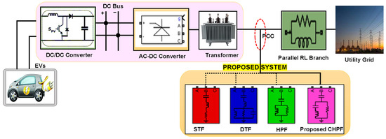
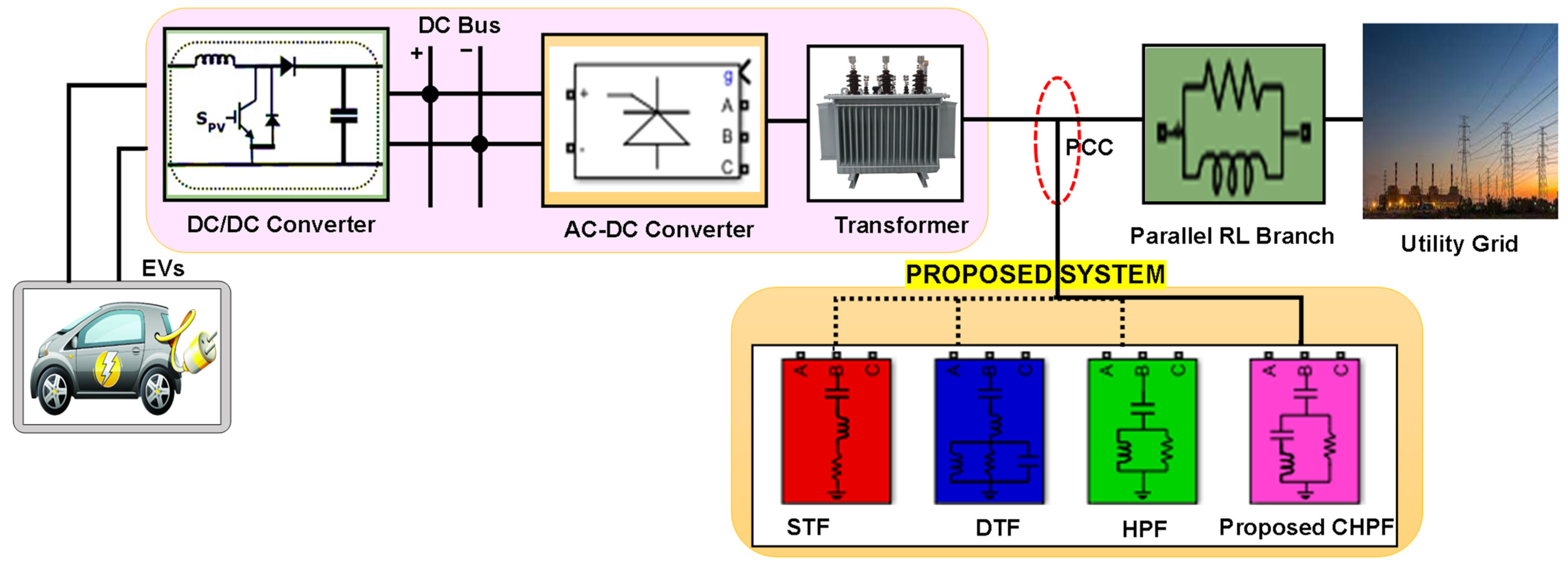
The proposed EV charging station (EVCS) is powered by a three-phase 440 V, 50 Hz utility grid, providing the electrical boundary conditions of the system and being the main source of AC input, as shown in Figure 1. The incorporation of passive damping of the low-order harmonic components also requires parallel connection of an RL branch at the common coupling point to prevent undesired resonance between the unwanted resonance and the downstream stages. This is connected to a three-phase transformer that ends up providing a voltage equalization and natural current smoothing because of its natural leakage inductance. A six-pulse controlled diode bridge rectifier is used to provide the AC-DC conversion. This offers a very sturdy and inexpensive interface but induces typical 5th, 7th, 11th, and 13th harmonic currents into the supply. This DC bus is filtered and fed to a high-power DC-DC converter to enable the charging of the 360 V, 300 Ah EV battery at a constant rate without causing any ripple or damaging the power transfer at high efficiency over the charging cycle.
Figure 1.
Design of a proposed high-performance harmonic filtered EVCS.
The STF has a series of CLR connections in shunt with the grid. The LC pair resonates and offers a very low impedance at its tuned frequency of a harmonic, thus diverting the given harmonic current over the series path. The DTF is constructed by connecting RLC branches in parallel, which is then connected in series with another CL section. Such an arrangement forms two resonant frequencies, which allows two prevalent harmonics to be suppressed simultaneously, though parallel and series resonant paths interact, making the arrangement more sensitive to the change in system impedance. In HPFs, parallel RL and in series with C form a high impedance at low frequencies and a lower impedance at higher frequencies. This causes the HPF to be useful in removing the higher-order harmonics and preserving the reasonable impedance of the fundamental frequency. It is due to this that the HPF can be employed to decrease other harmonics while still exhibiting reasonably good impedance at the fundamental frequency.
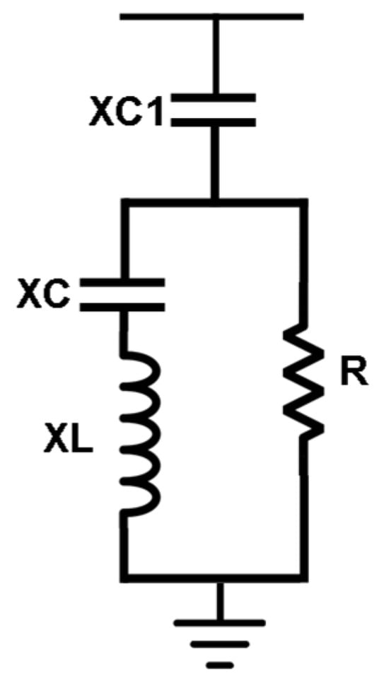
The CHPF is proposed to eliminate the low bandwidth, high reactive power requirement, and sensitivity, as shown in Figure 2. With its series parallel topology, high impedance at fundamental frequency, and well-damped low impedances in harmonic bands, it has better harmonic mitigation. The excellence of CHPF is that it can improve the impedance shaping, fundamental frequency rejection, and inherent damping simultaneously, unlike the structures of the conventional STF, DTF, and HPF.
Figure 2.
Proposed C-type high-pass harmonic filter.
The total frequency response of the CHPF is determined by the total impedance of the filter, which determines the way the filter changes to have low impedance at harmonic frequencies, represented in Equation (1).
where C1 is the series capacitor, which blocks the fundamental frequency response, as shown in Equation (2).
The C1 is calculated by Equation (3) to provide reactive power support and impedance shaping.
where Qc is the reactive power of 10 kVAR and VL-L is the line voltage of 440 V. At the harmonic frequencies, the filter inductor (L) and the parallel/auxiliary branch capacitor (C) are governed by Equation (4).
The low impedance equivalent is computed using Equation (5).
The quality factor is decreased in the internal damping resistor and is calculated from Equation (6). In the proposed C-type high-pass filter, a quality factor (QCHPF) is chosen as 2.3 to provide adequate parallel resonance damping and wideband harmonic rejection with low losses.
The resonance peaks were maintained using Equation (7),
Analytically, the filter parameters are calculated using the needs of reactive power compensation and harmonic tuning principles aligned with the current approaches to passive filter design [18]. The capacitor is determined by Equation (3), and the inductor is determined by the harmonic resonance condition Equation (4). The choice of damping resistance is based on the required quality factor of Equation (6) to provide a trade-off between harmonic attenuation and system stability [19]. The systematic procedure guarantees the reproducible and well-grounded choice of parameters. In a sensitivity analysis of a capacitance and inductance change of 10%, the tuning frequency varies slightly, with only slight effects (less than 2–3% change) on the performance of the THD. In line with recent studies of robustness of C-type filters [19,20], the design has a stable behavior and meets the IEEE 519 requirements of realistic component tolerances.
The analytical tuning of the filter parameters is followed by validation of the parameters by the simulation. The optimization factors consist of minimization of the voltage THD at the PCC, elimination of resonance amplification, allowable power factor, and minimization of fundamental frequency losses. There have been recent studies with similar multi-objective considerations of passive filter optimization [18]. The chosen quality factor can guarantee the right level of harmonic attenuation with no system instability. All these mathematical considerations are the reasons to consider the CHPF to be better and to select it as the offered harmonic mitigation option in EV charging stations.
The simulation of the grid-integrated EV charging station is done in MATLAB/Simulink (R2021a) in order to achieve reproducibility and transparency. Table 1 contains the detailed description of the simulation parameters. All filter parameters were computationally determined with the same system ratings, reactive power compensation, and quality factor to enable a fair and reproducible comparison of filter topologies. The C-type harmonic filter has the best harmonic attenuation with insignificant fundamental losses, so it is the best choice in the grid-connected EV charging system with improved power quality.
Table 1.
Simulation parameters of the charging station.
The point of common coupling (PCC) refers to the device that creates the interface between the utility grid of 440 V and the EV charging station transformer. The upstream grid is considered a rigid distribution system with short-circuit capacity that is much greater than the charger rating. Thus, the IEEE Std. 519 harmonic limits of strong systems can be used, and all the harmonic indices are assessed at the PCC.
The passive filter topology has different characteristics of operation. Single-tuned filters are highly selective to higher-order harmonics and have low sensitivity to detuning and grid impedance change [20]. The presence of double-tuned filters is able to reject a variety of harmonics at the cost of raising the structural complexity and sensitivity to tuning [18]. The high-pass filters provide a wideband attenuation at the expense of increased fundamental frequency attenuation. C-type filters, as mentioned in a recent optimization study [19], have the advantages of fundamental damping loss reduction and offer effective wideband harmonic suppression with the only problem of requiring careful parameter coordination to avoid resonance amplification. Selection of the topology is therefore based on the harmonic profile, the grid strength, and the operation requirement.
The passive filters are cheaper, more efficient, and easier to implement than active filtering methods, and therefore can be applied to high-power EV charging stations with deterministic harmonic spectra [19]. Active filters can also offer adaptive harmonic compensations, but add complexity, loss of switching and increased cost of investment. Thus, a C-type passive filter that is optimized can be viewed as an effective and cost-efficient option in quality-powered charging applications.
3. Results and Discussion
The efficacy of the proposed C-type high-pass harmonic filter is designed for EV charging stations, which is compared with traditional STF, DTF, and HPF-based charging stations across various power quality parameters, as discussed in the following subsections.
3.1. Voltage Characteristics
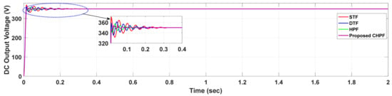
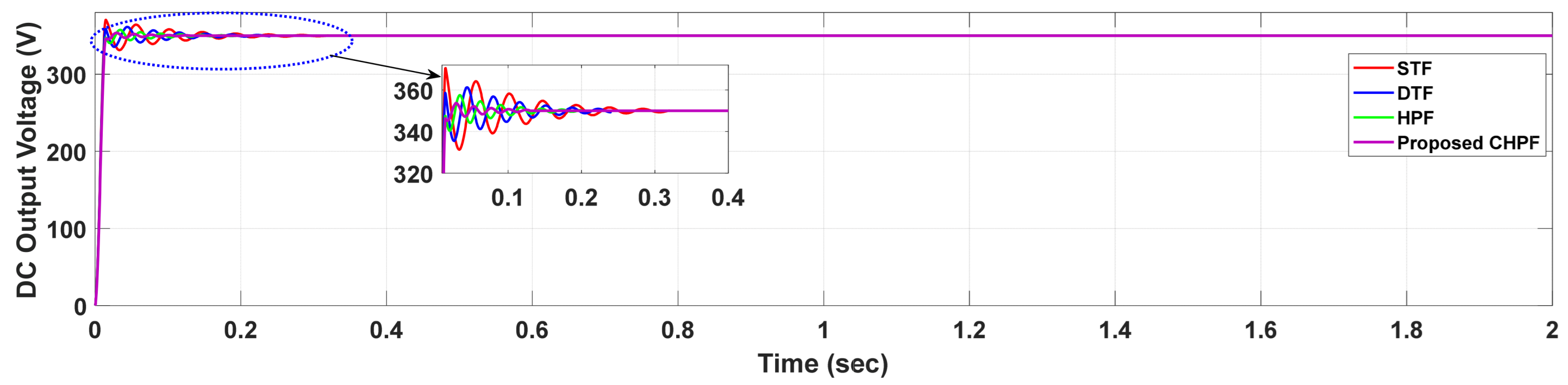
The dynamic response of the DC output voltage of the four filtering strategies, STF, DTF, HPF, and the proposed CHPF, at the transient period after a disturbance is shown in Figure 3. All filters are designed to control the DC-link voltage to the desired value of 350 V, but they settle out rather differently. The STF (red) has strong overshoot and slower oscillatory decay, and it takes almost 0–0.32 s to stabilize. The DTF (blue) exhibits lower oscillations than STF, but it also requires about 0–0.24 s to reach the steady state. The HPF (green) has a faster damping and a settlement time of 0–0.20 s, showing that it has a better transient response. The proposed CHPF (magenta), on the other hand, is the most stable and well-damped profile with minimal overshoot and the shortest settling time of 0–0.13 s, keeping the voltage very near the 350 V reference. The enlarged inset focuses on the initial transient period (0–0.4 s), and it is apparent that the proposed CHPF is effective in eliminating both under- and overshoots that are not otherwise reduced by other conventional methods of filtering. This proves its high dynamic performance and improved DC-link voltage regulation facility.
Figure 3.
Output voltage characteristics of a proposed high-performance harmonic filtered EVCS.
3.2. Power Factor and Efficiency Characteristics
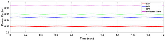
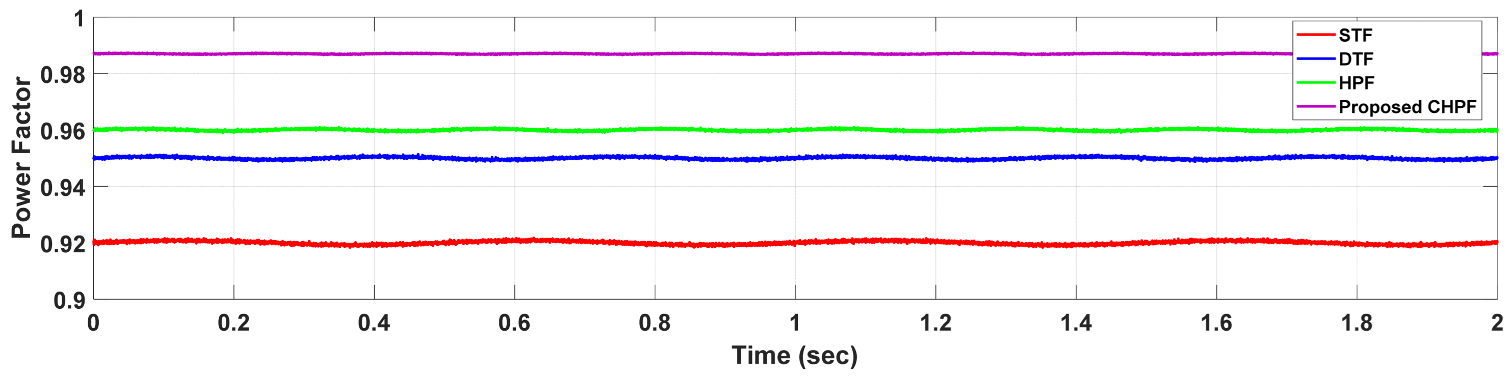
The comparative profiles of the power factor (PF) of the STF, DTF, HPF, and the proposed CHPF methods under steady-state operating conditions are shown in Figure 4. The STF has the lowest PF performance with an average value of about 0.92, with significant variations within the period of 2 s. The DTF increases the PF to about 0.95, with relatively fewer changes. The HPF also increases the PF to 0.96, showing more stable behavior as a result of better harmonic mitigation capacity. The proposed CHPF has the best and most steady power factor, which has an average PF of 0.987 with a small variation throughout the entire period. The high PF performance of the proposed CHPF implies that it has a good ability to suppress low-order harmonics and enhance the alignment of the input voltage and current waveforms. This is a clear indication that the CHPF is an effective means of guaranteeing power conversion quality and improved grid compliance as opposed to the available filtering schemes.
Figure 4.
Power factor characteristics of the proposed high-performance harmonic filtered EVCS.
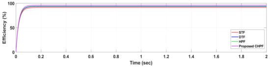
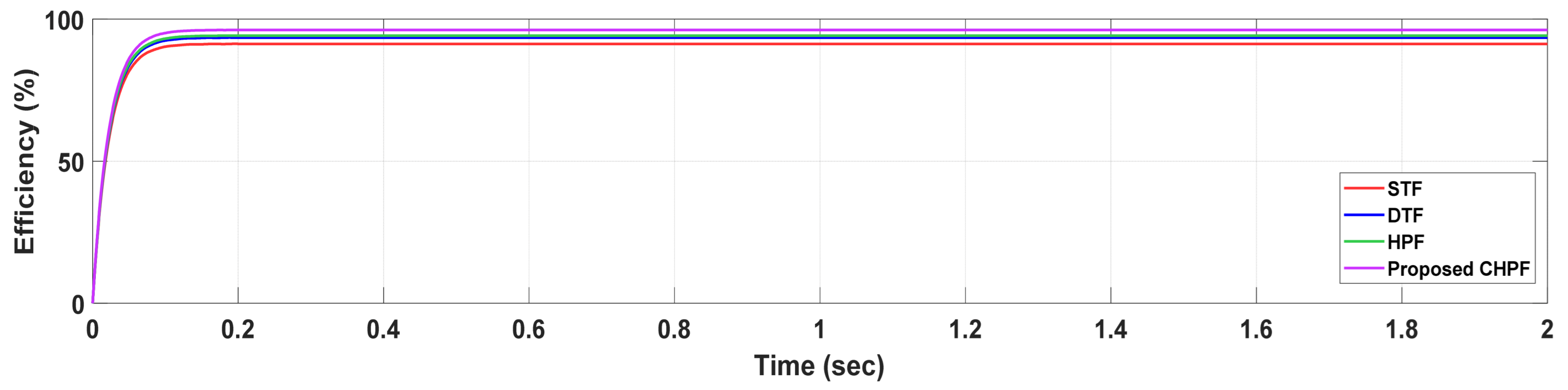
The dynamic efficiency response of the STF, DTF, HPF, and proposed CHPF configurations in terms of a 2 s operating interval is shown in Figure 5. Each of the methods demonstrates a high efficiency increase in the short-term transient phase that is attained by a steady-state regime in about 0.1 s. The STF has the lowest steady-state efficiency of 91.3%, which is due to more switching losses and inferior harmonic suppression. The DTF becomes moderate as it reaches 93.5%, and the HPF continues to increase efficiency to 94.2% by improving the reduction in ripple components. The proposed CHPF performs the best in terms of overall performance, achieving a steady-state efficiency of 96.2%, with less oscillatory behavior and less disjointed transient behavior. The excellent power conditioning ability, low harmonic loss, and high energy transfer properties of the proposed CHPF show its superior efficiency against traditional filtering techniques.
Figure 5.
Efficiency characteristics of a proposed high-performance harmonic filtered EVCS.
3.3. THD Analysis
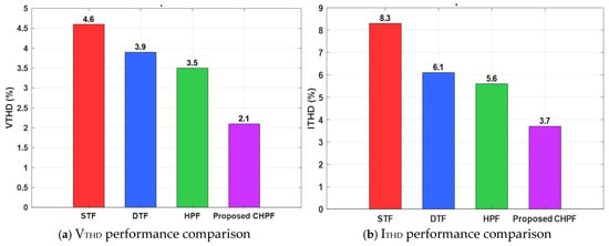
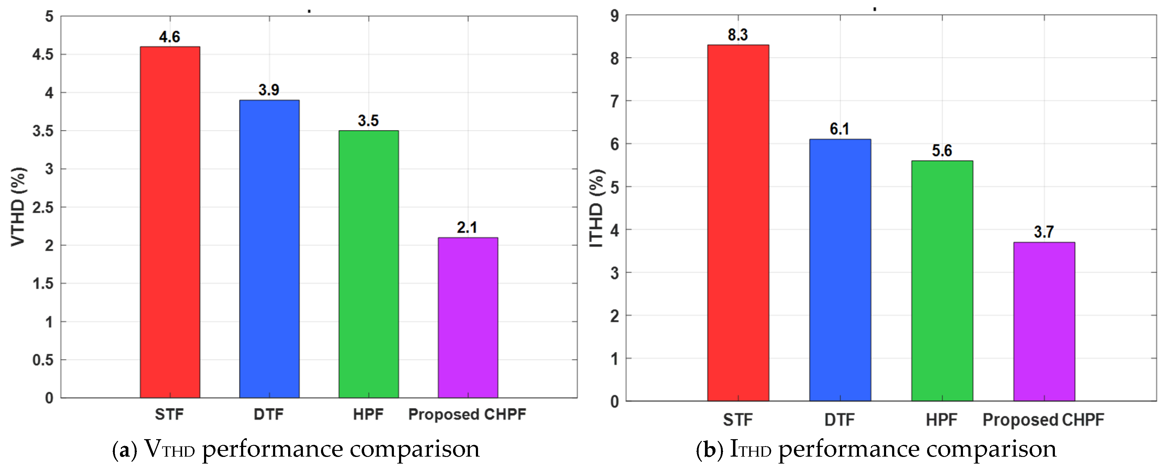
The harmonic performance of the STF, DTF, HPF, and proposed CHPF is shown in Figure 6. The STF is the most distorted in voltage (4.6%) and current (8.3%), which means that it has poor harmonic suppression. The DTF increases performance with the performance of VTHD of 3.9% and current THD of 6.1%, and the HPF further decreases the values to 3.5% and 5.6%, respectively. The proposed CHPF has the lowest distortion figures of VTHD of 2.1% and current THD of 3.7%, which indicate that it has a higher potential in reducing the major harmonic content all over the spectrum. These decreases confirm the usefulness of the CHPF in improving the quality of power and a high degree of adherence to IEEE 519 limits. Besides the overall THD, the prevalent harmonics (5th and 7th order) are practically eliminated at the PCC, which meets IEEE 519 recommended values.
Figure 6.
THD of (a) voltage, (b) current waveforms.
From these results, it is observed that there is a significant improvement in THD with the proposed charging station when compared to conventional methods.
The effectiveness of the proposed C-type high-pass harmonic filter topology simulation results are summarized in Table 2. Based on the quantitative analysis of all simulation results, it can be concluded that the performance of the proposed topology is superior to that of the conventional system.
Table 2.
Performance metric comparison of conventional and proposed systems.
4. Conclusions and Future Scope
This article had suggested a high-performance C-type high-pass harmonic filter (CHPF) of a three-phase grid-connected EV charging station to improve the quality of power. Other power quality parameters, including current and voltage THD, power factor, voltage regulation, dynamic response, and efficiency, were researched and compared between the conventional and a proposed scheme of filtering. The sum of the collective findings of the proposed system can be summarized as follows.
- ▪
- The simulated result of input current THD is 8.3% with the STF, 6.1% with the DTF, and 5.6% with the HPF. Conversely, the suggested CHPF reduces the existing THD to 3.7%, which meets the IEEE-519 harmonic requirements.
- ▪
- The THD of the voltage is 4.6%, 3.9%, and 3.5% of STFs, DTFs, and HPFs, respectively. When the proposed CHPF is involved, the voltage THD decreases significantly to 2.1%, and this implies that the voltage waveform quality and grid compliance are superior.
- ▪
- The input power factor obtained is 0.92 using a STF, 0.95 using a DTF, and 0.96 using a HPF. The proposed CHPF significantly increases the power factor value to 0.987 to guarantee that grid power is utilized more effectively and a lower level of reactive power is demanded.
- ▪
- The STF has an efficiency of 91.3%, DTF has an efficiency of 93.5%, and HPF has an efficiency of 94.2%. The proposed CHPF has the best efficiency of 96.2%, that is achieved by the minimization of harmonic losses and enhanced power conditioning.
- ▪
- The dynamic performance of DC-link voltage settles at 0.32 s, 0.24 s, and 0.20 s for the STF, DTF, and HPF, respectively. The proposed CHPF has the fastest and most well-damped response with a settling time of 0.13 s, where the DC voltage is still near its reference value.
- ▪
- The chosen quality factor (2.3) is sufficient to suppress the wideband harmonics with minimal system instability and minimum damping losses, which, in turn, justifies the reproducibility and applicability of the proposed filter design.
- ▪
- The parameters of the proposed C-type harmonic filter were calculated (C1 = 164 μF, C = 82 μF, 123 mH, and 0.43 Ω) to achieve a lossless response at the fundamental frequency and effective damping of harmonics.
Thus, according to the evidence of the achieved results of the proposed model, it can be stated that the C-type high-pass harmonic filter-based EV charging station is far better than the traditional STF, DTF, and HPF setups in terms of harmonic mitigation, voltage stability, power factor, and efficiency, as well as dynamic response. Therefore, the proposed CHPF can be suggested as one of the most efficient and grid-adaptive for use in high-power EV charging stations. The current research relies on analytical modeling and high-resolution simulation. It is noted that experimental validation in future work is required to continue to certify the feasibility of the practical execution of the proposed filter design.
Author Contributions
Conceptualization, S.M.; methodology, S.M.; formal analysis, Y.V.P.K.; validation, S.M. and Y.V.P.K.; data curation, Y.V.P.K.; resources, S.M. and Y.V.P.K.; investigation, Y.V.P.K.; writing—original draft preparation, S.M.; writing—review and editing, S.M. and Y.V.P.K.; visualization, S.M.; supervision, Y.V.P.K.; project administration, Y.V.P.K. All authors have read and agreed to the published version of the manuscript.
Funding
This research received no external funding.
Institutional Review Board Statement
Not applicable.
Informed Consent Statement
Not applicable.
Data Availability Statement
Data are contained within the article.
Conflicts of Interest
The author declares no conflicts of interest.
References
- Duffey, C.K.; Stratford, R.P. Update of harmonic standard IEEE-519: IEEE recommended practices and requirements for harmonic control in electric power systems. IEEE Trans. Ind. Appl. 2002, 25, 1025–1034. [Google Scholar] [CrossRef] [Scilit]
- Yousuf, A.K.M.; Wang, Z.; Paranjape, R.; Tang, Y. An In-Depth Exploration of Electric Vehicle Charging Station Infrastructure: A Comprehensive Review of Challenges, Mitigation Approaches, and Optimization Strategies. IEEE Access 2024, 12, 51570–51589. [Google Scholar] [CrossRef] [Scilit]
- Senol, M.; Bayram, I.S.; Hunter, L.; Sevdari, K.; McGarry, C.; Gaona, D.C.; Gehrke, O.; Galloway, S. Harmonics Measurement, Analysis, and Impact Assessment of Electric Vehicle Smart Charging. IEEE Open J. Veh. Technol. 2025, 6, 109–127. [Google Scholar] [CrossRef] [Scilit]
- Roy, P.; Ilka, R.; He, J.; Liao, Y.; Cramer, A.M.; McCann, J.; Delay, S.; Coley, S.; Geraghty, M.; Dahal, S. Impact of Electric Vehicle Charging on Power Distribution Systems: A Case Study of the Grid in Western Kentucky. IEEE Access 2023, 11, 49002–49023. [Google Scholar] [CrossRef] [Scilit]
- Mamidala, S.; Venkata Pavan Kumar, Y.; Mallipeddi, R. Revolutionizing Electric Vehicle Charging Stations with Efficient Deep Q Networks Powered by Multimodal Bioinspired Analysis for Improved Performance. Energies 2025, 18, 1750. [Google Scholar] [CrossRef] [Scilit]
- Elazim, S.M.A.; Elkholy, M.H.; Elgarhy, A.; Senjyu, T.; Gamil, M.M.; Song, D.; Ali, E.S.; Ludin, G.A.; Irshad, A.S.; Lotfy, M.E. Enhancing Stability and Power Quality in Electric Vehicle Charging Stations Powered by Hybrid Energy Sources Through Harmonic Mitigation and Load Management. Sci. Rep. 2025, 15, 28077. [Google Scholar] [CrossRef] [Scilit]
- Mehmood, A.; Yang, F. Improvement of Power Quality of Grid-Connected EV Charging Station Using Grid-Component Based Harmonic Mitigation Technique. Energies 2025, 18, 2876. [Google Scholar] [CrossRef] [Scilit]
- Mamidala, S.; Pavan Kumar, Y.V. Closed-Loop Battery Current-Controlled Zeta Converter for Improved Power Quality in Electric Vehicle Charging Stations. Trans. Energy Syst. Eng. Appl. 2024, 5, 1–19. [Google Scholar] [CrossRef] [Scilit]
- Mamidala, S.; Prajapati, A.K. Grid-Integrated EV Charging Infrastructure. In Recent Advances in Power Electronics and Drives—Select Proceedings of EPREC 2023; Lecture Notes in Electrical Engineering; Springer: Cham, Switzerland, 2024; Volume 1139, pp. 297–323. [Google Scholar] [CrossRef] [Scilit]
- Mamidala, S.; Kumar, Y.V.P. Zeta Converter Integration for Improved Power Quality in Bidirectional V2G Energy Charging Stations. Results Eng. 2025, 28, 107346. [Google Scholar] [CrossRef] [Scilit]
- Cheepati, K.R.; Parimalasundar, E.; Suresh, K.; Reddy, C.R.; Alqahtani, M.M.; Khalid, M. Design of Triple Tuned Passive Harmonic Power Filter—A Novel Approach. IEEE Can. J. Electr. Comput. Eng. 2023, 46, 270–277. [Google Scholar] [CrossRef] [Scilit]
- Saini, M.; Gautam, D.D.; Saini, S.; Chaudhary, S.K.; Srivastava, P.C.; Srivastava, K.; Sharma, A.K. Pursuance of a Passive Filter for a Multi-Coil EV Charger Employing a Solar-Connected System to Enhance Power Quality. Int. J. Power Electron. Drive Syst. 2024, 15, 1818–1825. [Google Scholar] [CrossRef] [Scilit]
- Malik, M.I.; Hamdani, Y.M.; Nurdiansyah, R.; Faridah, L. Hybrid Double-Tuned and High-Pass Filter for Harmonic Mitigation in Inverter HVAC Systems. Electron J. Ilm. Tek. Elektro 2025, 6, 139–152. [Google Scholar] [CrossRef] [Scilit]
- Thamizh Thentral, T.M.; Usha, S.; Palanisamy, R.; Geetha, A.; Alkhudaydi, A.M.; Sharma, N.K.; Bajaj, M.; Ghoneim, S.S.M.; Shouran, M.; Kamel, S. An Energy Efficient Modified Passive Power Filter for Power Quality Enhancement in Electric Drives. Front. Energy Res. 2022, 10, 989857. [Google Scholar] [CrossRef] [Scilit]
- Malik, M.I.; Ihsanto, E. Design and Simulation of Second-Order High-Pass Filter and C-Type Filter for Reducing Harmonics as a Power Quality Improvement Effort in the Automotive Industry. J. Integr. Adv. Eng. 2023, 3, 23–36. [Google Scholar] [CrossRef] [Scilit]
- Karadeniz, A.; Balci, M.E. Comparative Evaluation of Common Passive Filter Types Regarding Maximization of Transformer’s Loading Capability under Non-Sinusoidal Conditions. Electr. Power Syst. Res. 2018, 158, 324–334. [Google Scholar] [CrossRef] [Scilit]
- Shakeri, S.; Esmaeili, S.; Koochi, M.H.R. Passive Harmonic Filter Design Considering Voltage Sag Performance—Applicable to Large Industries. IEEE Trans. Power Deliv. 2022, 37, 1714–1722. [Google Scholar] [CrossRef] [Scilit]
- Costa, V.; Torquato, R.; Rosado, B.; Argüello, A.; Freitas, W. Multi-objective programming method for passive filter tuning. IEEE Trans. Power Deliv. 2026, 41, 1–4. [Google Scholar] [CrossRef] [Scilit]
- Ugwuagbo, E.; Ray, B.; Balogun, A.; Okafor, F.; Sul, J.; Nabi, N.; Datta, U. Power quality assessment and harmonic mitigation at the point of common coupling of industrial load. J. Control. Autom. Electr. Syst. 2026, 1–14. [Google Scholar] [CrossRef] [Scilit]
- Davoodi, M.; Hoevenaars, P.; Kaleybar, H.J.; Brenna, M. Advanced universal hybrid power filter configuration for enhanced harmonic mitigation in industrial power systems: A field-test approach. Energies 2026, 19, 700. [Google Scholar] [CrossRef] [Scilit]
- Tamaskani, R.; Khodsuz, M.; Yazdani-Asrami, M. Optimal Design of C-Type Filter in Harmonics Polluted Distribution Systems. Energies 2022, 15, 1587. [Google Scholar] [CrossRef] [Scilit]
- Mohd Nor, K.A.; Abdullah, N. Power Quality Improvement of Three-Phase Electrical Systems Using Active–Passive Hybrid Harmonic Filter. Results Eng. 2024, 22, 102242. [Google Scholar] [CrossRef] [Scilit]
- Wu, H.; Zeng, L.; Ren, Q.; Ai, L. Robust Design Scheme of C-Type Filter Considering Harmonic Dynamic Characteristics of Traction Power Supply System. IEEE Access 2022, 10, 47782–47791. [Google Scholar] [CrossRef] [Scilit]
- Wang, Y.; Yin, K.; Liu, H.; Yuan, Y. A Method for Designing and Optimizing the Electrical Parameters of Dynamic Tuning Passive Filter. Symmetry 2021, 13, 1115. [Google Scholar] [CrossRef] [Scilit]
- Mboving, A.; Stéphane, C.; Hanzelka, Z.; Firlit, A. Analysis of the Factors Having an Influence on the LC Passive Harmonic Filter Work Efficiency. Energies 2022, 15, 1894. [Google Scholar] [CrossRef] [Scilit]
- Mariscotti, A.; Giordano, D.; Signorino, D. Energy Efficiency Improvement with Reversible Substations for Electrified Transportation Systems. Open Transp. J. 2023, 17, 17. [Google Scholar] [CrossRef] [Scilit]

Disclaimer/Publisher’s Note: The statements, opinions and data contained in all publications are solely those of the individual author(s) and contributor(s) and not of MDPI and/or the editor(s). MDPI and/or the editor(s) disclaim responsibility for any injury to people or property resulting from any ideas, methods, instructions or products referred to in the content. |
© 2026 by the authors. Licensee MDPI, Basel, Switzerland. This article is an open access article distributed under the terms and conditions of the Creative Commons Attribution (CC BY) license.