


Abstract
Autoclaved aerated concrete (AAC) masonry offers low self-weight and favorable thermal insulation, but its porous, relatively brittle matrix creates challenges for structural reliability and environmental durability. This study presents a targeted narrative critical review of experimental and numerical research on AAC manufacturing, pore structure, block–mortar interaction, seismic and blast behavior, hygrothermal performance, durability, and sustainability. Findings are critically compared in relation to material density, joint configuration, loading history, and moisture exposure, with emphasis on mechanisms connecting material-scale characteristics to wall-scale response. The synthesis indicates that stronger mortar adhesion can redirect cracking from joints into AAC units, while prior in-plane seismic damage can diminish subsequent out-of-plane resistance through cracking and loss of boundary restraint. Moisture accumulation increases thermal conductivity and can weaken masonry bonds, whereas freeze–thaw deterioration depends strongly on saturation and material properties. Strengthening benefits vary with reinforcement, anchorage, and test configuration and cannot be treated as universal improvement factors. Likewise, potential operational and structural environmental savings must be weighed against autoclaving energy and maintenance demands. The review identifies priorities for matched-condition testing, coupled hygrothermal–mechanical assessment, sequential seismic evaluation, and assembly-specific performance-based design guidance.
1. Introduction
The construction sector is exploring lower-mass envelope and masonry materials that can meet thermal and structural requirements while limiting life-cycle impacts. AAC is produced from cement and/or lime, finely divided silica sources such as quartz sand or fly ash, water, a gas-forming aluminum agent, and, in many formulations, gypsum or anhydrite. Its cellular structure reduces unit weight but introduces trade-offs among stiffness, cracking resistance, insulation, and water absorption. Accordingly, engineering performance must be evaluated for the material, the mortar joints, the wall assembly, and the environmental exposure—not inferred from block density alone.
This review addresses unreinforced AAC masonry units and panels, not Reinforced Autoclaved Aerated Concrete (RAAC)—the precast, steel-reinforced AAC planks used historically for roof and floor decking that have been the subject of recent high-profile structural failures internationally.
The use of AAC masonry has increased significantly over the past several decades, and along with it interest in studying all its behaviors and characteristics. Fundamental properties were the focus of initial research on AAC but as its applications spread throughout building construction research has expanded greatly. Uses of AAC masonry as infill in framed structural systems and as structurally significant load-bearing walls in low- to mid-rise buildings has led to a large body of work concerning its bond behavior, seismic response, durability under multiple stressors, and how to increase its structural performance to better compete with traditional masonry units. Moving away from traditional thick-bed mortar (10–12 mm) joints to polymer-modified thin bed mortar (1–3 mm) joints also drastically changed AAC construction practice by limiting thermal bridging effects across bed joints and reducing localized stress concentrations.
As ref. [1] discussed, tensile bond strength testing of AAC blocks can be used to gain knowledge about bond behavior of the adhesion point between masonry units and mortar. Identifying these forces allows for the creation of more accurate mathematical models used for analysis of infilled framed structures. Further interest in AAC is attributed to its superior thermal efficiency [1,2]. Unfortunately, high-performance characteristics like thermal resistance can be degraded by environmental conditions such as moisture ingress [3,4].
Previous reviews have established an important foundation for understanding the physical, mechanical, and thermal properties of AAC masonry. In particular, ref. [5] provides a comprehensive synthesis of AAC material characteristics, masonry assemblage behavior, experimental testing procedures, and relationships between measured properties and European design provisions. Their review also identified variability in experimental results arising from differences in testing methods and masonry configurations. Nevertheless, important questions remain regarding how material-scale characteristics and environmental deterioration interact with masonry-level load transfer, cracking, and residual structural performance. The present review builds upon this foundation by adopting a mechanism-oriented, cross-scale perspective that examines the relationships among AAC microstructure, block–mortar compatibility, seismic damage accumulation, strengthening systems, and hygrothermal durability, rather than evaluating these performance characteristics independently.
Four interrelated research questions guide this critical synthesis. First, how do hydrothermal phase development, pore-wall integrity, and pore connectivity influence mechanical resistance beyond the effects of bulk density alone? Second, under what conditions does increasing mortar strength or interfacial adhesion improve composite masonry resistance, and when does it instead promote brittle cracking within the relatively weak AAC units? Third, how does accumulated in-plane damage alter the boundary contact, arching action, and residual out-of-plane resistance of AAC masonry infill walls during subsequent seismic loading? Fourth, how do moisture ingress, freeze–thaw exposure, and interfacial deterioration interact to influence long-term structural capacity and thermal performance? By integrating findings from material characterization, masonry experiments, seismic investigations, and durability studies, the review identifies potential connections between these mechanisms and the limitations of interpreting isolated experimental results as universally applicable design relationships. It further distinguishes seismic demand reduction from structural resistance and highlights why strengthening gains reported for different reinforcement and confinement configurations cannot be directly compared without considering specimen geometry, loading conditions, and failure criteria. The resulting contribution is a conceptual framework for identifying coupled deterioration mechanisms, critical experimental variables, and performance-based research priorities. These interpretations constitute testable hypotheses derived from existing evidence rather than newly validated constitutive models or experimental findings.
The present study adopts a targeted narrative review approach to critically examine existing research on autoclaved aerated concrete (AAC) masonry. The literature discussed includes peer-reviewed journal articles, conference proceedings, and relevant material specifications and structural design standards, with emphasis on manufacturing and microstructure, mechanical properties, block–mortar interaction, seismic performance, hygrothermal behavior, and durability. The synthesis is organized thematically and evaluates published findings in relation to their experimental conditions, material characteristics, structural configurations, and limitations. Particular attention is given to identifying consistent observations, explaining differences in reported performance, and establishing relationships between material-scale characteristics and masonry-level structural behavior. Unlike a systematic review, the present study did not employ a predefined exhaustive search strategy, formal eligibility-screening procedure, or standardized risk-of-bias assessment. Furthermore, the absence of a documented database-specific search history and defined search period limits the reproducibility and completeness of the literature selection. Consequently, potential selection and publication biases cannot be excluded, and the findings should not be interpreted as a comprehensive quantitative synthesis of all available evidence. Nevertheless, the principal contribution of this review lies in integrating previously reported experimental and analytical findings to identify governing mechanical mechanisms, clarify the limitations of existing interpretations, and establish research priorities for improving the structural performance and durability of AAC masonry.
2. Fundamental Properties and Manufacturing of AAC
A thorough understanding of the manufacturing process and the resulting microstructural and physical properties is essential to appreciate the behavior of AAC in masonry applications. These fundamental characteristics are the root cause of both its significant advantages and its vulnerabilities.
2.1. Composition and Manufacturing Process
AAC production uses finely ground quartz sand or alternative silica-bearing materials (including suitably characterized fly ash), portland cement and/or lime as calcium sources, water, and small quantities of aluminum powder or paste; gypsum or anhydrite may be added to regulate setting and reaction chemistry. The raw-material proportions control alkalinity, dissolution kinetics, and the overall Ca/Si ratio. A Ca/Si value around 0.8–1.0 may favor 11 Å tobermorite formation in some conventional recipes, but it is a formulation-dependent target rather than a universal optimum or evidence of complete conversion. The theoretical Ca/Si ratio of idealized 5CaO·6SiO2·5H2O is approximately 0.83. Actual mineral assemblages also depend on reactive rather than merely total silica, aluminum and sulfate availability, particle fineness, autoclave temperature, residence time, and steam conditions [5,6].
First, the raw materials are batched and mixed to form a slurry. The aluminum powder reacts with the alkaline hydroxides in the slurry (from lime and cement) to produce microscopic hydrogen gas bubbles. This reaction is represented as
2Al + 3Ca (OH)2 + 6H2O → 3CaO · Al2O3 · 6H2O + 3H2↑
The formation of hydrogen gas causes the slurry to expand, much like a bread dough, doubling its original volume. This “cake” is then allowed to rest and undergo initial setting, a process known as pre-curing. Once the cake has achieved sufficient green strength, it is mechanically wire-cut into blocks or panels of the desired dimensions. This precision cutting produces units with very tight dimensional tolerances. The final and most critical stage is autoclaving. The cut units are placed in large pressure vessels called autoclaves and subjected to saturated steam at high temperatures (around 180–200 °C) and pressures (around 10–12 bar) for a period of 8 to 12 h. The main manufacturing stages are shown schematically in Figure 1.
Figure 1.
Key stages of AAC production from batching and mixing to autoclave curing.
During autoclaving, the calcium-bearing and siliceous constituents undergo a sequence of hydrothermal reactions that progressively modify the mineralogical composition and microstructure of AAC. Initial hydration and hydrothermal reactions produce poorly crystalline calcium–silicate–hydrate (C–S–H) phases, which subsequently react with dissolved silica and may progressively transform into crystalline 11 Å tobermorite. Ref. [7] demonstrated that calcium-rich C–S–H phases form during the early stages of autoclaving and evolve toward tobermorite as silica dissolution and hydrothermal curing proceed. The development of these phases depends on the effective Ca/Si ratio, silica reactivity, calcium availability, aluminum and sulfate content, curing temperature, steam pressure, and treatment duration. Although Ca/Si ratios around 0.8–1.0 may favor tobermorite formation in certain conventional AAC formulations, the optimum ratio is composition-dependent and should not be treated as a universal requirement. Insufficient reaction time or limited silica dissolution may result in incomplete phase development, whereas excessive or otherwise unsuitable hydrothermal treatment can alter the resulting mineral assemblage. Consequently, the mechanical properties of AAC depend on the extent and spatial uniformity of the hydrothermal reactions rather than the nominal Ca/Si ratio or autoclaving temperature alone [5,6,8].
The contribution of tobermorite to AAC mechanical performance is closely associated with its crystallinity, morphology, and distribution within the porous solid matrix. Tobermorite commonly develops as plate-like or lath-like crystals that may intergrow with other calcium–silicate–hydrate products along pore walls and within the solid ligaments separating adjacent aeration pores. Such intergrowth can contribute to a more continuous cementitious framework and improve local load transfer, provided that pore-wall thickness and structural continuity are maintained. However, the presence of highly crystalline tobermorite does not necessarily imply greater macroscopic strength. The mechanical response also depends on the distribution of crystalline and poorly crystalline hydration products, the geometry of load-bearing pore walls, local defects, and microcrack development. Ref. [7] observed increasing strength during hydrothermal phase evolution even when total pore volume remained approximately unchanged, indicating that changes in the cementitious matrix can influence strength independently of overall porosity. Furthermore, ref. [9] reported that an AAC formulation containing calcined diatomaceous earth achieved its highest compressive strength despite relatively limited tobermorite formation. These findings demonstrate that tobermorite content alone is not a sufficient indicator of mechanical performance and that other C–S–H phases and pore-structure characteristics must also be considered.
From a structural perspective, the relationship between hydrothermal phase evolution and macroscopic mechanical behavior can be interpreted through the integrity of the porous load-bearing framework. Pore walls containing well-distributed hydration products and continuous solid connections may exhibit more effective stress transfer, whereas thin ligaments, heterogeneous mineral distributions, and pre-existing defects can create localized stress concentrations and initiate fracture. Similarly, dimensional stability depends on the combined effects of hydration-product characteristics, pore structure, moisture condition, and shrinkage behavior rather than the presence of crystalline tobermorite alone. Establishing quantitative relationships among these variables requires complementary characterization methods, including quantitative X-ray diffraction (XRD), scanning electron microscopy with energy-dispersive spectroscopy (SEM–EDS), pore-structure analysis, and mechanical testing. Comparisons should be performed using specimens with approximately matched dry density, porosity, and moisture content while systematically varying Ca/Si ratio and hydrothermal curing conditions. Such investigations would help distinguish the contribution of mineralogical development from geometric effects associated with the porous matrix and provide a stronger basis for predicting AAC stiffness, strength, and fracture resistance.
In particular, the nominal Ca/Si ratio should not be confused with the local chemistry of the pore walls, and an increase in detected tobermorite reflections does not establish uniform crystals throughout a block. A test program capable of resolving these effects would combine quantitative XRD or solid-state characterization with image analysis of pore-wall ligament thickness, three-dimensional porosity, and compression/tension tests. Comparing specimens of similar density but different autoclaving histories would separate mineralogical effects from overall void fraction.
2.2. Microstructural Characteristics and Basic Mechanical Properties
AAC contains gas-generated macropores (often approximately 0.5–2 mm) and smaller pores in the hydrated solid matrix, with total porosity varying substantially across density classes [10]. Total void fraction largely governs dry density, but it does not uniquely specify pore diameters, shape, spacing, connectivity, local pore-wall thickness, or microcrack population. Gas pores can be approximately rounded and partly isolated, whereas connected capillary pores and construction microcracks establish paths for fluid transport. Thus AAC should be described as a multiscale pore network containing both relatively isolated voids and connected moisture-transport pathways, not as an entirely closed-pore solid. Figure 2 schematically illustrates this multiscale pore architecture, highlighting the relationship among gas-generated macropores, interconnected capillary pores, microcracks, and the hydrated solid matrix.
Figure 2.
Conceptual illustration of the multiscale pore structure of autoclaved aerated concrete (AAC), showing gas-generated macropores, matrix and capillary pores, interconnected moisture-transport pathways, and the calcium–silicate–hydrate (C–S–H)/tobermorite-rich solid matrix. The illustration is schematic and does not represent experimental microscopy or quantitative measurements.
The mechanical and thermal performance of AAC is governed by the combined effects of total porosity, pore morphology, spatial distribution, and the characteristics of the solid matrix. Total porosity represents the overall volume fraction occupied by voids and is closely related to dry bulk density for AAC products with comparable solid-phase compositions. Increasing total porosity generally decreases thermal conductivity by reducing the proportion of the more conductive solid phase, but it also reduces the effective load-bearing area and, consequently, compressive strength and stiffness. Nevertheless, bulk density alone does not adequately characterize the internal arrangement of pores. AAC specimens with similar densities and overall porosities may exhibit different pore-size distributions, pore-wall thicknesses, pore connectivity, and microcrack populations. These differences can influence local stress transfer and heat-conduction pathways, producing variations in mechanical and thermal responses even when the total void fraction remains approximately unchanged [10,11].
From a mechanical perspective, the porous matrix transfers applied stresses through interconnected solid ligaments separating adjacent pores. The thickness, continuity, and spatial distribution of these ligaments influence local stiffness and the development of stress concentrations. Relatively uniform pore distributions and continuous pore walls can promote more effective load transfer, whereas pore clustering, irregularly shaped voids, thin ligaments, and pre-existing microcracks may facilitate crack initiation and propagation. Consequently, two AAC specimens with comparable densities may exhibit different compressive strengths and fracture characteristics because their weakest load-bearing regions differ. Thermal transport, in contrast, occurs primarily through conduction in the hydrated solid framework and the gas occupying the pores under ordinary dry service conditions. Pore morphology and the connectivity of solid conduction paths can influence effective thermal conductivity beyond the effect of total porosity. Interconnected capillary pores also provide pathways for moisture penetration, which can substantially increase thermal conductivity as pore air is replaced by water. Thus, pore connectivity may influence thermal performance indirectly through moisture accumulation while also affecting mechanical deterioration and fracture susceptibility [10,12].
Ref. [11] experimentally investigated the influence of pore size on AAC specimens with approximately comparable apparent densities. For the investigated B04 AAC specimens, an increase in mean pore diameter from approximately 0.35 to 0.45 mm was associated with an approximately 23% increase in thermal conductivity, whereas compressive strength increased by only about 7%, with considerable scatter in the mechanical results. These observations indicate that pore-size variation can affect thermal conductivity more strongly than compressive strength within the investigated material system. However, pore refinement should not be interpreted as an unconditional means of improving insulation without mechanical consequences. Such a relationship is physically plausible when refinement produces a relatively uniform distribution of smaller aeration pores without substantially increasing total porosity, connected capillary porosity, pore-wall defects, or the discontinuity of the solid load-bearing framework. It also requires that the composition, integrity, and mechanical properties of the hydrated pore-wall matrix remain approximately unchanged. Conversely, excessive pore subdivision accompanied by thinning of load-bearing ligaments, pore clustering, or microcrack formation may reduce strength and fracture resistance despite potential thermal benefits. The observed relationship is therefore conditional on the combined effects of pore geometry, solid-matrix continuity, and moisture state rather than pore diameter alone. Further experimental investigations using matched-density specimens with independently characterized pore connectivity, ligament thickness, and microcrack distributions are necessary to establish transferable relationships between microstructure, thermal conductivity, and mechanical performance.
The ranges frequently cited for conventional AAC—dry density approximately 400–800 kg/m3, compressive strength around 2–7 MPa, and elastic modulus around 1.5–4.5 GPa—describe different products and test programs, not matched observations along a universal constitutive curve. In general, higher density leaves a larger solid load-carrying fraction and tends to increase stiffness and strength while raising dry thermal conductivity; mineralogy, defects, pore morphology, moisture and specimen geometry create substantial scatter. The approximately isotropic behavior identified by [13] concerns a tested masonry assemblage and its modeling assumptions, rather than a guarantee that each manufactured AAC block is direction independent. Casting-rise orientation and joints can produce direction-sensitive deformation or fracture; isotropic modeling should be justified by the tested wall system and loading conditions. These limitations matter when selecting design parameters outside the experimentally calibrated density or mortar class.
2.3. The Lightweight Advantage and Sustainability Credentials
The low density of AAC provides several potential structural and construction advantages. On the one hand, a lighter building reduces the dead load, allowing for savings on size and cost of structural components such as columns, beams, foundation. On the other hand, ref. [14] observed this advantage in the seismic performance evaluation of AAC masonry: the light weight leads to a lower seismic mass, which directly results in lower earthquake inertial forces. Lower earthquake inertial forces can be linked to better seismic performance of AAC construction.
The sustainability advantages of AAC should be evaluated through a life-cycle perspective that considers environmental impacts associated with raw-material production, manufacturing, transportation, construction, building operation, maintenance, and end-of-life treatment. Although the relatively low density of AAC can reduce structural dead loads and potentially decrease material requirements for supporting beams, columns, and foundations, such benefits depend on whether the building design is actually optimized to take advantage of the reduced mass. Similarly, the thermal insulation properties of AAC may contribute to lower operational heating and cooling demands, but the magnitude of these savings depends on climate, wall configuration, thermal bridging, moisture condition, and the performance of the alternative wall system. These potential advantages must be balanced against the environmental burdens of cement and lime production, silica processing, and energy-intensive hydrothermal curing. In particular, autoclaving requires pressurized steam at elevated temperatures to promote the formation of calcium–silicate–hydrate phases, including tobermorite, which are important for developing the required material properties. Ref. [15] conducted a cradle-to-gate life-cycle assessment of autoclaved aerated fly-ash and concrete block production in China and identified fly-ash slurry preparation, lime grinding, and steam curing as major contributors to the investigated environmental impacts. Steam curing accounted for approximately 19.62% of the total environmental load reported for that specific production system. This result demonstrates that autoclaving represents an important manufacturing burden, although its relative contribution depends on the raw-material composition, process efficiency, energy source, and assessment methodology. Consequently, the environmental performance of AAC cannot be inferred from its lightweight characteristics or thermal properties alone.
A comprehensive assessment should also consider the influence of long-term durability and maintenance on environmental performance. Moisture accumulation within AAC increases effective thermal conductivity and can reduce the operational energy benefits associated with its cellular structure [3,12]. Furthermore, prolonged wetting, interfacial deterioration, and freeze–thaw damage may necessitate maintenance of exterior finishes, localized repairs, or premature replacement of affected components. These interventions introduce additional material, energy, transportation, and waste-management burdens over the building service life. Protective renders and water-repellent treatments may reduce moisture ingress and extend durability, but their manufacture, installation, maintenance, and replacement must also be considered. Accordingly, a meaningful life-cycle assessment should compare functionally equivalent wall assemblies with consistent requirements for thermal performance, structural resistance, fire safety, and service life. The analysis should incorporate cradle-to-grave system boundaries, realistic maintenance and replacement scenarios, regional energy-generation characteristics, and moisture-dependent operational performance. Only such an assessment can establish whether the environmental savings achieved during construction and operation outweigh the impacts associated with manufacturing and long-term deterioration.
The incorporation of alternative siliceous materials, including fly ash and other industrial residues, introduces additional opportunities and trade-offs. Replacing virgin silica sources with industrial by-products may reduce primary resource consumption and divert waste from disposal; however, the environmental benefit depends on the origin, processing requirements, transport distances, and allocation of environmental burdens associated with the secondary material. Moreover, variations in reactive silica content, Ca/Si ratio, aluminum availability, alkalinity, and impurities can influence hydrothermal reaction kinetics and the formation of crystalline tobermorite. These changes may alter the morphology and continuity of the hydrated pore-wall matrix, thereby affecting AAC compressive strength, density, thermal conductivity, and durability. For example, ref. [16] investigated municipal-solid-waste-incineration fly ash as an alternative AAC constituent and demonstrated that washing and substitution level significantly influenced material properties. Moderate incorporation of washed fly ash improved compressive strength within the investigated formulations, whereas higher replacement levels inhibited tobermorite formation and reduced strength. These findings are specific to the studied waste-derived material and should not be generalized to conventional coal fly ash or other industrial residues. They nevertheless illustrate that increasing secondary-material content does not necessarily produce simultaneous environmental and mechanical improvements. Therefore, sustainable AAC development requires coordinated evaluation of feedstock chemistry, hydrothermal phase evolution, pore structure, mechanical resistance, moisture-related durability, and life-cycle environmental impacts rather than maximizing waste incorporation independently of material performance.
A functional comparison should specify an equivalent thermal transmittance, fire/sound requirements, load-bearing or infill function, and service life for the AAC and comparator walls. The inventory must include raw-material extraction, grinding, lime/cement manufacture, autoclave steam and fuel, aeration and cutting losses, reinforcement, delivery, and installation. Use-stage operational energy savings should be modeled for climate and moisture-dependent conductivity, while repairs, renders, rain barriers, and replacement cycles should be included as scenarios. Alternative fly ash or industrial siliceous residues can improve resource efficiency but can also change alkalinity and reaction kinetics; altered tobermorite and pore-wall development may require increased curing energy or compromise durability. No universal carbon benefit can be concluded from low density alone without a quantified, location-specific life-cycle inventory.
3. Mechanical and Structural Performance of AAC Masonry
The structural application of AAC masonry requires a deep understanding of its behavior not just as individual units, but as a composite system comprising blocks, mortar, and often reinforcement. This section reviews the key mechanical properties of the AAC masonry system and its performance under various structural loads.
3.1. Compressive Strength and Elastic Modulus
AAC masonry compressive resistance depends jointly on block strength, mortar and joint properties, geometric tolerances, and workmanship. Ref. [17] characterized mechanical properties of AAC and its masonry; ref. [18] specifically examined bond behavior of several joint materials. A stronger mortar can increase composite load transfer when joint failure controls, but the gain is not monotonic: a joint stiffer or stronger than the adjacent AAC can concentrate stresses and initiate block cracking or crushing. Therefore the appropriate design target is compatible block–mortar deformation and controlled failure, not maximum mortar strength in isolation.
A critical aspect of assessing in-situ strength is the use of non-destructive or semi-destructive testing methods. Ref. [19] validated the use of such techniques, specifically P-wave velocity testing, for determining the compressive strength of AAC units. They established a statistically significant empirical relationship that can account for varying moisture levels, providing a means of assessing compressive strength in existing structures without causing significant damage. This is useful for quality control and the evaluation of existing AAC constructions.
Ref. [8] examined strength-improvement approaches for a solid-waste-based AAC system, including carbonation-related modification and pressurized processing. The reported combination achieved approximately 12.3 MPa at a dry density around 857 kg/m3. That result lies above the commonly quoted 400–800 kg/m3 density range and should not be represented as a routine lightweight AAC grade. Compared with a product near 400 kg/m3, 857 kg/m3 more than doubles the dry mass per unit volume; thermal conductivity and structural self-weight therefore require independent verification rather than being assumed unchanged. The appropriate comparison is strength-to-density and whole-wall thermal performance at matched service requirements, not peak strength alone. Figure 3 synthesizes factors governing strength, assessment, and reported modification approaches, drawing on several separate studies.
Figure 3.
Schematic representation of (A) principal factors influencing AAC masonry compressive strength; (B) non-destructive compressive-strength assessment; and (C) selected material modification strategies for improving compressive strength. The illustration conceptually synthesizes findings discussed in [8,17,18,19].
Elastic modulus governs deformation, lateral stiffness, and stress redistribution. The approximately 1.5–4.5 GPa range discussed for AAC products varies with density, moisture, pore structure, and testing method; masonry modulus additionally reflects joint compliance and cracking. There is no single verified E–compressive-strength relationship for all density grades or mortar systems. Designers should prioritize measured properties or code-calibrated correlations for the relevant masonry assemblage and distinguish block stiffness from composite wall stiffness [5,13].
3.2. Material Tensile Properties and Failure Mechanisms
Interface and unit failure mechanisms must be distinguished according to the testing configuration. Cross-couplet and triplet tests are commonly used to evaluate tensile and shear bond strength at masonry joints, respectively, whereas splitting tensile tests assess the tensile resistance of masonry units through diametral compression. Diagonal-compression tests, in contrast, are used to investigate the in-plane response and cracking behavior of masonry panels under diagonal loading. Ref. [20] evaluated splitting tensile methods, not the diagonal-compression apparatus shown in Figure 4. For AAC, measured tensile resistance depends on pore-wall fracture as well as the strength of the block–mortar interface. A change in the location of the first crack—from mortar bond to the AAC unit—may indicate improved adhesion without demonstrating improved post-peak ductility or wall-level seismic resilience.
Figure 4.
Conceptual schematic illustrating the diagonal-compression loading arrangement used to investigate the in-plane response of AAC masonry panels. The illustration is schematic and does not represent a specific experimental apparatus.
3.3. Bond Strength at the Block–Mortar Interface
The bond strength at the block–mortar interface is critical for the composite action of AAC masonry, directly influencing its tensile, shear, and flexural resistance. Ref. [1] evaluated this behavior by conducting experimental tests on cross-couplet specimens for tensile bond strength and triplet specimens for shear bond strength. Their work provided data on adhesion characteristics relevant to the stability of masonry constructions. A common observation in bond-strength tests, as noted by [17], is that failure may occur at the block–mortar interface, as displayed in Figure 5, marking this zone as a potential weak link.
Figure 5.
Schematic representation of bond failure mechanisms at the block–mortar Interfacial Transition Zone (ITZ) in AAC masonry: (a) tensile bond failure in a cross-couplet test configuration and (b) shear bond failure in a triplet test configuration.
Ref. [18] reported improved tensile and shear bond using a cement-slurry coating before applying conventional sand–cement mortar. The coating can modify near-surface suction and joint adhesion, but a stronger interface also changes the weakest component of the assemblage. If adhesive capacity exceeds the tensile or shear strength of the AAC, stresses may localize in the porous unit and yield more abrupt block fracture. Similarly, a large elastic-modulus mismatch between a dense mortar layer and a low-modulus AAC unit can concentrate deformation near joint ends, corners, or openings. The required mortar specification must therefore balance adhesion, modulus, joint thickness, fracture energy, workability, and moisture compatibility; strength gains from tests of one mortar family should not be extrapolated automatically to thin-bed joints [18,21].
The bond behavior is also sensitive to environmental conditions and loading rates. Ref. [4] identified moisture content as a severely detrimental factor, with wet conditions leading to drastic reductions in bond strength. Additionally, ref. [22] found that bond shear strength increases with higher strain rates and pre-compression levels, which is an important consideration for dynamic loading scenarios such as earthquakes or impacts.
The interaction between interfacial strength and masonry failure is therefore governed by competing limit states involving joint debonding, frictional sliding, mortar cracking, and fracture within the AAC units. The dominant mechanism may change with axial pre-compression, cyclic displacement history, moisture condition, and reinforcement configuration. Although bed-joint reinforcement and external strengthening systems may improve crack control and redistribute stresses, their effectiveness also depends on adequate anchorage and compatibility with the relatively brittle AAC substrate. Structural resilience should therefore be evaluated using multiple performance indicators rather than peak strength alone, including initial cracking resistance, stiffness degradation, ultimate displacement, failure localization, hysteretic energy dissipation, and residual load-bearing capacity. Experimental comparisons conducted using matched AAC density classes, mortar properties, joint thicknesses, and loading conditions would provide a more reliable basis for identifying mortar systems that achieve sufficient interfacial resistance without inducing premature brittle block failure [18,21,23,24].
3.4. Shear Behavior and Confinement Effects
The in-plane shear strength of AAC masonry walls is important for resisting lateral loads from wind or earthquakes. The shear behavior is complex, influenced by factors such as aspect ratio, vertical pre-compression, and the presence of confinement. Ref. [23] studied the effect of horizontal reinforcement on the compression and shear strength of AAC walls. They found that incorporating bed joint reinforcement, particularly of the steel structural truss type, improved both the compressive and shear strength. The technique of applying mortar on both the upper and lower bed surfaces (double jointing) was also shown to improve load-bearing capacity.
Confinement can delay unstable diagonal cracking and modify lateral load paths, but quantitative improvements depend on the configuration being compared. Ref. [25] tested 18 confined AAC walls (nominal density class 600), with and without central window openings, under prescribed vertical compression. For walls with an approximately 1.5 m2 opening, adding reinforced-concrete confinement at the opening’s vertical edges produced about 45% higher maximum horizontal force relative to specimens with perimeter confinement only; the authors reported only a marginal change in ductility for that particular comparison. The 45% figure must not be reinterpreted as the gain from combining generic bed-joint reinforcement with confinement. In structural design, such confinement works by restraining crack opening, transferring stresses through boundary elements, and modifying failure mechanisms; detailing and anchorage determine how much post-cracking displacement can actually be accommodated. A schematic representation of an AAC masonry wall incorporating confinement elements and bed-joint reinforcement is presented in Figure 6.
Figure 6.
Schematic representation of a confined AAC masonry wall system incorporating confinement elements and bed-joint reinforcement.
Ref. [26] showed that confining AAC masonry with steel-fiber-reinforced concrete can enhance its seismic performance in low-rise buildings in low-to-moderate seismic zones. This technique improves structural resilience while eliminating traditional formwork and reinforcement cutting, and using gas-formed (lightweight) concrete provides good thermal insulation and reduces manual labor. The lower self-weight decreases seismic demands, making it a potential alternative to conventional brick masonry.
Taken together, the investigations identify different effects of reinforcement, joint detailing, and confinement on masonry strength and deformation. The percent improvements reported in confinement tests cannot be added to CFRP or GFRP gains or ranked as universal material advantages: the former compares specific confined walls with different opening details and axial prestress, whereas FRP studies use externally bonded composite strips and different geometries, adhesives, and failure criteria. Capacity, initial stiffness, drift at damage, energy dissipation, and residual strength should be reported separately. In particular, higher peak load does not by itself establish greater ductility or more reliable out-of-plane retention after cracking.
4. Performance Under Extreme and Dynamic Loads
4.1. Seismic Performance of AAC Masonry Structures
The low mass of AAC walls can reduce inertial earthquake demand, but low mass is not equivalent to high lateral resistance. Unreinforced AAC may experience joint slip, diagonal cracking, local block crushing, or premature loss of stability; adequate ductility and load-path continuity must be established separately. In-plane response, out-of-plane restraint, and damage accumulated between loading directions should be assessed as a coupled system rather than independent wall capacities.
4.1.1. In-Plane Seismic Behavior
The in-plane behavior of AAC walls governs their response to seismic shaking parallel to the wall plane. Ref. [27] performed early work in this area, conducting experimental tests on unreinforced AAC masonry panels to develop seismic design parameters. They calibrated a macro-element model using the experimental results to simulate AAC’s nonlinear response to seismic loads, then extended this same model to three-dimensional simulations of complete AAC masonry buildings using the TREMURI program. Seismic performance was assessed through both nonlinear static pushover and nonlinear dynamic time-history analyses.
Ref. [21] experimentally investigated the in-plane seismic behavior of six AAC self-insulation block masonry walls subjected to pseudo-static cyclic loading. The results demonstrated that mortar-joint configuration significantly influenced cracking resistance, lateral load-bearing capacity, deformation characteristics, and failure patterns. For the reported comparison, walls incorporating thin-layer mortar joints exhibited approximately 13.1% higher initial cracking resistance but approximately 4.5% lower ultimate lateral load capacity than those constructed with thicker insulation mortar joints. The thin-layer mortar specimens also exhibited intersecting diagonal cracks and greater internal damage within the AAC blocks, illustrating the possibility that improved joint integrity may redirect failure into the relatively weaker masonry units. Separately, ref. [28] reported that AAC masonry constructed with thin-layer mortar joints exhibited improved compressive performance but lower average shear strength along mortar joints compared with the thicker insulation mortar joints examined in their investigation. These findings emphasize that the influence of mortar joints depends on the loading mechanism and the specific mortar–block combination. Consequently, the failure-mode transition illustrated in Figure 7 should be interpreted as a potential consequence of enhanced interfacial load transfer rather than evidence that stronger joints necessarily improve seismic ductility or post-cracking resistance. The mechanical compatibility of AAC blocks and mortar joints must therefore be assessed through both strength and deformation-based criteria.
Figure 7.
In-plane failure mode of AAC masonry characterized by block cracking and crushing due to high-strength thin-layer mortar joints.
For AAC used as infill in reinforced concrete frames, a probabilistic approach has been recommended. Ref. [29] argued that uncertainties in the strength properties of AAC block masonry necessitate a probabilistic evaluation of its in-plane seismic response, proposing statistical treatments for key strength parameters. Separately, ref. [30] validated numerical models against full-scale experimental testing of AAC panel-assembled walls, providing further evidence that, despite their lower strength, these walls can meet building-code reliability requirements in high-seismicity areas when properly modeled and detailed.
4.1.2. Out-of-Plane Behavior and Interaction Effects
The in-plane (IP) and out-of-plane (OOP) seismic responses of AAC masonry infill walls are mechanically coupled because damage accumulated during lateral drift can alter the load-transfer mechanisms governing subsequent transverse resistance. Under cyclic IP displacement, masonry units and mortar joints may develop diagonal cracking, interfacial sliding, joint opening, local block crushing, and separation from the surrounding reinforced-concrete frame. These damage mechanisms reduce the continuity and stiffness of the masonry assemblage while modifying the contact conditions required for OOP resistance. In particular, the OOP stability of a sufficiently restrained infill wall may depend partly on compressive arching action, through which transverse loading mobilizes in-plane compression between the wall and its supporting boundaries. However, residual cracks, deteriorated mortar joints, and gaps at the wall–frame interface can interrupt this compressive load path, reduce effective boundary restraint, and limit the development of arching resistance. Consequently, previously damaged infill walls may exhibit lower OOP stiffness, reduced transverse load-bearing capacity, and increased susceptibility to displacement instability or expulsion. These effects are interdependent: cracking within AAC units can reduce the continuity of compression paths, while joint degradation and boundary separation may promote additional cracking and localized deformation under subsequent OOP loading.
Experimental evidence of this interaction was provided by [24], who investigated the OOP seismic performance of full-scale AAC infill walls subjected to prior IP cyclic displacement reversals. Their investigation demonstrated that diagonal cracking developed at an IP drift ratio of approximately 0.002, below the 0.005 drift ratio subsequently imposed before OOP testing. For the unreinforced specimens, prior IP cycling to a drift ratio of 0.005 reduced peak OOP resistance by approximately 34.7% and OOP secant stiffness by 85.9% relative to the undamaged reference wall. These results demonstrate that substantial deterioration in transverse stiffness and resistance can occur even when the preceding IP deformation remains within certain prescribed drift limits. The study also showed that conventional OOP strength predictions based on idealized boundary-support conditions may overestimate the resistance of previously damaged AAC infills when the effects of accumulated IP cracking are not considered. Nevertheless, the relative contributions of unit cracking, mortar-joint degradation, and boundary-contact deterioration were not independently quantified. The experimental findings therefore establish the significance of IP–OOP interaction but do not provide a universally applicable reduction factor for all AAC infill configurations.
Bed-joint reinforcement offers a potential means of mitigating coupled seismic deterioration by bridging cracks, improving post-cracking integrity, and redistributing tensile forces across damaged masonry regions. Ref. [24] reported that, following the same prior IP drift ratio of 0.005, flat-truss and cord-type bed-joint reinforcement increased peak OOP resistance by approximately 29.7% and 23.4%, respectively, relative to the previously damaged unreinforced specimen. The cord-type reinforcement also provided greater ultimate OOP displacement and energy dissipation than the flat-truss configuration under the investigated conditions. The reinforcement configurations investigated in this study, including the unreinforced reference wall and the flat-truss and cord-type bed-joint reinforcement arrangements, are illustrated schematically in Figure 8. These results indicate that reinforcement can improve residual OOP performance despite accumulated IP damage, although they do not establish complete recovery of the undamaged wall capacity. Furthermore, reinforcement effectiveness depends on anchorage, bond integrity, crack-bridging capacity, and the preservation of adequate boundary restraint. If substantial wall–frame separation prevents the development of compressive arching, reinforcement within mortar joints alone may not restore the original structural load path. Accordingly, assessing AAC infill performance under realistic multidirectional earthquake loading requires sequential IP–OOP testing, direct measurement of residual cracking and boundary separation, and evaluation of OOP strength, stiffness, displacement capacity, and stability after defined levels of prior damage [24].
Figure 8.
Schematic representation of bed-joint reinforcement layouts for AAC masonry walls studied by [24].
A useful sequential-damage assessment would specify IP drift history, measure residual gap opening and joint damage, and then apply OOP pressure or displacement to the same wall. Comparison with previously undamaged walls would isolate the effect of lost arching action and boundary contact. The approach would also allow anchored reinforcement and confinement to be assessed on residual capacity rather than on undamaged peak strength alone.
HDC and textile-grid reinforced overlays have been investigated as means of improving out-of-plane resistance [31]. Conceptually, distributed crack bridging can support deformation compatibility, while anchored confinement may help maintain frame contact and compression arching. However, these mechanisms are not interchangeable: externally bonded FRP may debond, bed-joint reinforcement may lose effectiveness if its anchorage deteriorates, and overlays may transfer high stresses to weak AAC substrates. Future tests should impose calibrated in-plane drift histories followed by out-of-plane loading and report residual strength, boundary separation, anchorage failure, and energy dissipation for identical wall configurations.
4.1.3. Retrofitting and Strengthening for Seismic Resilience
For existing unreinforced or under-reinforced AAC masonry, several retrofitting techniques have been investigated to improve seismic resistance and deformation capacity. Ref. [32] evaluated high-ductility fiber-reinforced concrete (HDC) strengthening systems under reversed cyclic in-plane loading and reported improvements in shear resistance and energy dissipation. However, the resulting deformation capacity depended on the strengthening configuration. In particular, the HDC-strip-retrofitted specimen exhibited negligible improvement in displacement ductility, despite improvements in other seismic response parameters. These findings demonstrate that the use of a high-ductility strengthening material does not necessarily produce a proportional improvement in the ductility of the complete masonry wall. Strengthening effectiveness must therefore be evaluated according to reinforcement configuration, bond and anchorage conditions, failure mechanisms, and the measured displacement response rather than inferred from material properties alone.
Ref. [33] investigated externally bonded fiber-reinforced-polymer (FRP) strips on AAC masonry. For the tested configurations, reported capacity increases of approximately 48% with CFRP and 56% with GFRP accompanied different stiffness and ductility responses. These values are conditional on strip layout, anchorage, substrate condition, and the study’s loading and failure criteria. CFRP and GFRP differ in elastic modulus, strain capacity, bond behavior, and debonding mode. A larger maximum-force gain with one composite does not demonstrate better stiffness retention, cyclic energy dissipation, or residual displacement capacity. Nor can the separate approximately 45% confinement improvement be ranked directly against these composite effects, because the control walls, loading conditions, and governing failures differed between investigations. The qualitative strengthening mechanisms associated with these retrofit approaches are illustrated in Figure 9.
Figure 9.
Conceptual illustration of AAC masonry strengthening with high-ductility overlays and externally bonded FRP; qualitative mechanisms.
Additional strategies include glass-fiber geogrids [34], steel flat-truss bed-joint reinforcement [35], and precast construction-column confinement of desert-sand AAC walls [36,37]. Ref. [36] experimentally investigated the seismic performance of five desert-sand AAC masonry wall specimens measuring 1.27 × 1.73 × 0.25 m, subjected to low-cycle reversed lateral loading under constant axial compressive stresses ranging from 0.1 to 0.3 MPa. The specimens incorporated different precast construction-column configurations, including water-resistant gypsum and concrete columns, with additional steel reinforcement in one specimen. The experimental results indicated cracking loads ranging from 27.0 to 64.0 kN and ultimate lateral load-bearing capacities between 52.04 and 84.35 kN, corresponding to ultimate lateral drift ratios of approximately 1.26–2.03%. In this study, the cracking load represents the lateral force at the onset of visible cracking, while the ultimate load refers to the maximum lateral resistance attained during cyclic loading. The lateral drift ratio is defined as the horizontal displacement normalized by the wall height. The authors further evaluated deformation capacity using two distinct ductility coefficients: the ultimate ductility coefficient (λ = Δu/Δcr) and the breaking ductility coefficient (μ = Δd/Δcr), where Δcr, Δu, and Δd represent the lateral drifts at cracking, peak resistance, and the post-peak breaking stage, respectively. For specimen WS-5, incorporating steel reinforcement within the water-resistant gypsum construction columns, the reported coefficients were λ ≈ 7.18 and μ ≈ 11.87, indicating greater deformation capacity beyond peak resistance. However, these coefficients are referenced to the cracking drift rather than a conventional yield displacement and should not be interpreted as standardized seismic ductility factors. Furthermore, the reported strength and deformation characteristics are specific to the investigated wall configurations, axial loading conditions, and experimental procedures.
The effectiveness of AAC masonry strengthening techniques varies with the reinforcing material, installation configuration, masonry properties, axial loading, and testing procedure. Consequently, improvements in lateral strength, deformation capacity, and energy dissipation should not be interpreted as equivalent measures of ductility. Ref. [33] reported that CFRP strengthening increased load-bearing capacity by approximately 48% and provided substantial post-cracking deformation capacity for the investigated strip arrangement, whereas GFRP produced an approximately 56% increase in load-bearing capacity but comparatively limited ductility. Ref. [34] observed improvements in ultimate resistance and displacement capacity with increasing glass-fiber geogrid reinforcement ratios under the investigated loading conditions, with the response also influenced by vertical compressive stress. Furthermore, the ductility coefficients reported for precast-column-confined AAC walls by [36] were referenced to cracking displacement rather than conventional yield displacement, limiting direct comparison with other investigations. These findings demonstrate that the structural benefits of HDC overlays, FRP composites, geogrids, and confinement systems depend on the particular wall configuration and governing failure mechanism. Accordingly, comparisons should separately evaluate peak resistance, displacement ductility, post-peak deformation, stiffness degradation, and energy dissipation using clearly defined and consistent experimental criteria. No universal ductility improvement or relative ranking of these strengthening techniques can be established from the available studies.
4.1.4. Case Studies and Real-World Performance
Insights from real-world events are valuable for validating laboratory findings. Ref. [38] presented damage assessments of AAC buildings from Italian case studies, including the 2012 Emilia earthquake and 2016 Central Italy earthquakes. Their analysis showed that modern AAC buildings, engineered to current seismic codes, demonstrated better damage resistance compared to older structures damaged in the Emilia earthquake. While some damage to non-structural AAC walls was observed following the Central Italy earthquake, the overall performance supported its potential for seismic applications when properly designed.
Ref. [14] investigated the seismic response of a six-storey (G + 5) reinforced-concrete framed building incorporating AAC block and conventional red-brick infill walls using ETABS under seismic Zone III conditions. Their numerical analysis indicated that the AAC-infilled configuration exhibited approximately 77–79% lower storey displacement in the Y-direction and 78–81% in the X-direction than the corresponding red-brick configuration. The reported reductions in maximum storey displacement, storey drift, and base shear were approximately 77.3%, 36.1%, and 26.46%, respectively. The substantially greater reduction in displacement compared with base shear requires careful interpretation because these parameters represent different aspects of structural response. Base shear is influenced by seismic mass and the dynamic characteristics of the building, whereas lateral displacement also depends on effective stiffness, natural vibration periods, mode shapes, and the distribution of lateral forces. Consequently, displacement reductions are not necessarily proportional to reductions in base shear. In a simplified linear representation, displacement is approximately proportional to lateral force divided by effective stiffness; therefore, the reported displacement difference cannot be explained by reduced seismic force alone without considering changes in the structural response characteristics. Although the lighter AAC infill reduces structural mass, the original investigation does not provide sufficient independent stiffness and modal-response information to quantify the relative contributions of these mechanisms to the unusually large displacement reductions. Accordingly, the reported percentages should be regarded as study-specific numerical results rather than generally applicable seismic performance improvements. In particular, reduced base shear indicates a reduction in calculated seismic demand and does not independently demonstrate greater lateral load-bearing capacity, ductility, or collapse resistance. Further comparative investigations using consistently defined infill stiffness, mass distributions, and validated structural models are needed to establish the transferability of these findings.
4.2. Performance of AAC Under Blast Loads
Investigations of AAC masonry under blast loading have demonstrated that wall geometry, boundary conditions, and blast characteristics significantly influence structural response and failure mechanisms. Ref. [39] investigated AAC masonry walls using finite-element models developed in ABAQUS/Explicit, considering wall thicknesses of 150, 200, and 250 mm, TNT charge masses of 5 and 7 kg, and stand-off distances of 2, 5, and 10 m. The numerical analyses, supported by experimental characterization of constituent material properties, demonstrated that thinner walls and shorter stand-off distances generally produced greater deformation and damage under the investigated loading conditions. The findings emphasize the influence of wall thickness and blast intensity on structural vulnerability. However, these results primarily describe the predicted response of masonry wall assemblies under specified loading and modeling assumptions and should not be interpreted as direct experimental evidence of strain-rate-dependent constitutive behavior of AAC. Further validation of numerical predictions against wall-level blast experiments is necessary to establish their broader applicability.
Similarly, ref. [40] investigated AAC masonry walls subjected to vented gas explosions through nine full-scale tests and complementary numerical simulations. The results revealed predominantly one-way and two-way flexural failure mechanisms, with wall thickness, boundary restraint, and the pressure–time characteristics of the explosion significantly influencing structural response, while variations in block strength had a comparatively smaller effect within the investigated range. Ref. [41] experimentally evaluated four full-scale AAC masonry wall specimens, including unreinforced reference walls and walls strengthened with polymer coatings applied to one or both surfaces. Their findings demonstrated that polymer strengthening improved wall integrity and reduced blast-induced damage under the investigated loading conditions, although severe damage remained possible under higher blast intensities. The researchers also employed the cohesive zone method (CZM) to simulate progressive block separation and wall failure, obtaining reasonable agreement with the observed experimental failure patterns. Collectively, these studies provide valuable insights into the blast resistance, deformation characteristics, and failure mechanisms of AAC masonry systems. However, the reported findings primarily describe the structural response of wall assemblies and do not, by themselves, establish comprehensive strain-rate-dependent constitutive properties of AAC. Further experimental investigations integrating dynamic material characterization, wall-level blast testing, and validated numerical modeling are therefore necessary to develop reliable performance-based design approaches for AAC masonry subjected to extreme dynamic loading.
5. Hygrothermal and Durability Aspects of AAC Masonry
While the structural performance of AAC is important, its widespread adoption is also driven by its high thermal insulation capacity. However, these thermal properties are closely linked to its hygric behavior, presenting a dual characteristic of performance advantage and environmental vulnerability.
5.1. Thermal Performance and Energy Efficiency
The thermal performance of AAC masonry depends on material conductivity, wall thickness, mortar-joint configuration, moisture condition, and surface heat-transfer resistance. Ref. [28] experimentally determined a mean thermal transmittance of 0.558 ± 0.003 W/(m2·K) for 250-mm-thick, unplastered AAC self-insulation masonry walls. The tested AAC blocks had an average dry density of approximately 558 kg/m3, a measured moisture content of 1.3%, and a dry thermal conductivity of 0.11 W/(m·K). For a homogeneous AAC layer, the simplified relationship U = λ/d gives 0.44 W/(m2·K) when surface resistances are neglected. However, this calculation does not represent the complete masonry assembly because it excludes mortar-joint thermal bridging, moisture-dependent conductivity, and surface heat-transfer conditions. In their theoretical analysis, ref. [28] adopted an adjusted AAC thermal conductivity of 0.13 W/(m·K) to account for moisture-related effects and considered parallel heat-transfer pathways through AAC blocks and mortar joints. The experimentally measured thermal transmittances were 0.559, 0.561, and 0.555 W/(m2·K) for the three investigated unplastered wall configurations, respectively. The difference between the idealized homogeneous-layer calculation and the measured wall transmittance therefore reflects the importance of assembly-level heat transfer and the limitations of using dry block conductivity alone. The reported 1.3% moisture content characterizes the tested AAC blocks and should not be interpreted as an independently measured uniform moisture condition throughout the wall assembly. Consequently, the reported thermal transmittance is specific to the investigated wall thickness, material properties, joint configurations, and laboratory conditions and should not be generalized to other AAC masonry systems without appropriate thermal assessment. Beyond bulk density, pore characteristics also influence thermal performance. Ref. [11] demonstrated that, at approximately comparable density and porosity, increasing pore size was associated with higher thermal conductivity, while its influence on compressive strength was relatively limited. This relationship was attributed to differences in heat-transfer pathways through the porous matrix, indicating that pore-size refinement may improve thermal insulation without substantial strength reduction under the investigated conditions. Furthermore, increasing wall thickness generally enhances thermal resistance by extending the heat-conduction path, whereas moisture accumulation within the pore network increases effective thermal conductivity and reduces insulation performance. Therefore, the thermal efficiency of AAC masonry should be assessed by considering the interactions among density, pore structure, wall thickness, and moisture conditions rather than relying solely on dry material properties.
From a life-cycle perspective, the favorable thermal conductivity of AAC represents a potential operational-energy advantage rather than direct evidence of lower whole-building environmental impacts. The heat-transfer coefficient reported by [28] applies to a specific wall configuration and moisture condition; it cannot independently establish heating and cooling energy savings relative to alternative wall systems. Such benefits must be determined through building-level energy simulations or measurements that consider climatic conditions, thermal bridging, moisture-dependent conductivity, and equivalent functional requirements. Moreover, the operational savings should be evaluated alongside the embodied impacts of AAC manufacturing, including autoclaving, and the maintenance and replacement demands associated with long-term environmental exposure [3,12]. Consequently, evaluating AAC sustainability requires integration of material-level thermal characteristics with whole-building life-cycle assessment rather than relying on nominal insulation performance alone.
5.2. The Critical Impact of Moisture on Performance and Durability
Moisture transport in AAC takes place through connected portions of its capillary and microcrack network despite the presence of relatively isolated aeration voids. Water replaces low-conductivity pore air and raises effective thermal conductivity; ref. [12] observed values up to approximately sixfold higher under water saturation than in dry specimens. Temperature and moisture gradients may also alter local swelling/shrinkage, stresses at interfaces, and the propagation of existing microcracks under service load. Thus, heat flow, capillary suction, vapor diffusion, and fracture should not be modeled as completely independent phenomena. The magnitude of coupling varies with pore connectivity, exposure duration, coating properties, and drying opportunity; the combined effects remain incompletely quantified for AAC masonry assemblies.
The effectiveness of exterior renders, water-repellent treatments, and insulation systems in controlling AAC moisture exposure depends on their combined resistance to liquid-water penetration and capacity to permit vapor diffusion and subsequent drying. Although protective coatings can reduce rainwater absorption, coatings with high water-vapor diffusion resistance may restrict outward drying when moisture enters through cracks, defective joints, construction moisture, or imperfectly sealed interfaces. Such moisture retention can prolong elevated internal humidity, increase thermal conductivity, and potentially intensify freeze–thaw deterioration during cold-weather exposure. Ref. [3] demonstrated through transient hygrothermal simulations that climatic conditions, wind-driven rain, and exterior surface-layer properties substantially influence moisture accumulation and frost-damage potential in AAC masonry walls. In the investigated configurations, walls incorporating mineral-wool insulation exhibited faster drying following rainwater leakage than those incorporating expanded or extruded polystyrene insulation (EPS or XPS). These findings demonstrate that the moisture-control effectiveness of a protective system cannot be assessed from liquid-water resistance alone. Instead, the selection of exterior treatments should consider capillary absorption, vapor permeability, coating continuity, climatic exposure, and the availability of inward or outward drying pathways. Consequently, transient hygrothermal simulations incorporating realistic weather conditions, moisture-dependent material properties, and potential leakage scenarios are preferable to steady-state evaluations when assessing the long-term performance of protected AAC masonry assemblies.
Ref. [4] experimentally investigated the influence of moisture on the compressive and shear-bond strengths of AAC masonry constructed using conventional cement–sand mortars with mix ratios of 1:2, 1:4, and 1:6. The study considered oven-dried, air-dried, and wet conditions, with compressive strength evaluated using four-course masonry prisms and shear-bond strength assessed using three-course masonry triplets. Under wet conditions, the reported compressive strength reductions were 49.74%, 54.97%, and 59.85% for the respective mortar ratios, while corresponding shear-bond strength reductions were 44.3%, 61.1%, and 62.5%. These differences can be attributed, in part, to the distinct load-transfer and failure mechanisms associated with the two testing configurations. Under axial compression, masonry resistance depends on the combined mechanical response of AAC units and mortar joints, with moisture potentially affecting matrix stiffness, local deformation, and stress redistribution. Conversely, shear-bond resistance is more directly governed by adhesion, interfacial cohesion, and frictional resistance, which may be particularly sensitive to moisture accumulation at the block–mortar interface. Notably, compressive strength deterioration exceeded shear-bond deterioration for the richer 1:2 mortar mixture, whereas the leaner 1:4 and 1:6 mixtures exhibited greater relative reductions in shear-bond strength. This variation suggests that mortar composition and interfacial characteristics influence the relative sensitivity of different masonry resistance mechanisms to moisture exposure. However, the individual contributions of these mechanisms were not independently quantified in the reported results. Therefore, the observed strength reductions should be interpreted within the investigated specimen configurations, mortar compositions, and moisture conditions rather than generalized to all AAC masonry systems, particularly those incorporating polymer-modified thin-bed mortars.
5.3. Long-Term Durability and Freeze–Thaw Resistance
Freeze–thaw resistance is an important consideration in the long-term durability of AAC masonry, particularly in environments characterized by repeated moisture exposure and temperature fluctuations. The extent of deterioration depends on the degree of pore-water saturation, pore structure, and material strength. During freezing, the expansion of pore water and associated hydraulic pressures can induce microcracking within the porous matrix, potentially reducing mechanical strength and facilitating further moisture penetration. Under repeated environmental exposure, these processes may interact with existing cracks and block–mortar interfaces, contributing to progressive deterioration and reduced thermal insulation performance.
Ref. [12] experimentally investigated the freeze–thaw resistance of three commercially manufactured AAC products with nominal dry densities of 300–500 kg/m3 and compressive strength classes of approximately 1.8–4.0 MPa. The investigation involved 100-mm cubic specimens subjected to 25 and 50 freeze–thaw cycles, with each cycle consisting of freezing at −15 °C for 8 h followed by thawing at 20 °C for 8 h. Three initial moisture conditions were considered: dry specimens, specimens containing 10% moisture by volume, and capillary-water-saturated specimens. For the saturated condition, specimens were immersed in water for 48 h and subsequently maintained in sealed polyethylene bags for 24 h to promote moisture equilibration. Specimens with controlled initial moisture contents were maintained in sealed bags throughout cycling to limit moisture exchange. Freeze–thaw deterioration was evaluated through specimen mass loss and changes in compressive strength relative to reference specimens.
The experimental results demonstrated that freeze–thaw resistance was strongly influenced by initial moisture content and AAC strength class. For capillary-saturated specimens, ref. [12] reported compressive strength reductions of approximately 5.2–12.1% after 25 cycles, which they considered acceptable within the context of their experimental assessment. However, this classification represented a qualitative interpretation of the measured deterioration rather than compliance with an explicitly established numerical strength-loss acceptance criterion. The investigation followed ČSN EN 15304 testing procedures and evaluated frost resistance through mass loss and residual compressive strength. After 50 cycles under capillary-saturated conditions, the lower-strength P1.8-300 and P2-350 products experienced compressive strength reductions of approximately 46.0% and 45.7%, respectively, indicating substantial deterioration and loss of load-bearing effectiveness. In contrast, the higher-strength P4-500 product exhibited a smaller strength reduction of 16.6%, which the researchers considered satisfactory under the investigated conditions. Specimens initially containing 10% moisture by volume experienced strength reductions of approximately 6.3–16.3% after 50 cycles, while initially dry specimens exhibited negligible deterioration. These findings indicate that the acceptability of freeze–thaw damage cannot be determined solely from a specified number of cycles or a generalized percentage strength loss. Instead, it should be evaluated in relation to initial material strength, residual mechanical resistance, moisture exposure, intended structural function, and applicable design requirements. Consequently, the qualitative classifications reported by [12] should not be interpreted as universal durability acceptance limits or directly applied to complete AAC masonry assemblies without further verification.
From a structural durability perspective, repeated moisture ingress and freezing may progressively weaken AAC pore walls and aggravate existing cracks, particularly where drying is restricted. Although the experimental investigation by [12] focused on AAC material specimens rather than complete masonry assemblies, the findings highlight the need to consider moisture exposure when evaluating the long-term performance of AAC walls. Further studies incorporating mortar joints, sustained mechanical loading, and realistic wetting–drying cycles are required to establish reliable durability criteria for complete AAC masonry systems.
Coupled exposure is particularly important under mechanical load: a first freeze–thaw episode can open pore-wall cracks; subsequent wetting can then penetrate more deeply and intensify the next freezing event. Coating choice alters the rate of both wetting and drying, while pre-existing shear cracks create preferential routes around nominally water-resistant surfaces. A durability model should therefore track state variables including water content, temperature history, residual joint stiffness, and crack connectivity, rather than extrapolating from independent exposure tests.
6. Current Challenges, Standardization, and Future Research Directions
AAC adoption is constrained not only by material variability but also by the need to connect product qualification, wall-system design, boundary detailing, and service-life performance. Code fragmentation should be interpreted as an issue of differing scope and incomplete crosswalks, not as proof that the named standards contain directly contradictory numeric AAC design equations.
6.1. The Critical Gap in AAC Masonry Design Guidance
Despite advances in autoclaved aerated concrete (AAC) masonry research, significant challenges remain in translating experimental findings into consistent structural design guidance. Ref. [42] highlighted discrepancies among published AAC masonry investigations, particularly variations in experimental procedures and the resulting difficulties in developing uniform design relationships. One important example concerns the relationship between individual block properties and masonry assemblage resistance. AAC units with comparable compressive strength or density may exhibit different structural responses because of variations in mortar composition, joint thickness, interfacial adhesion, and stiffness compatibility [17,18]. Ref. [21] demonstrated that thin-layer mortar joints increased initial cracking resistance by approximately 13.1% while reducing ultimate lateral resistance by approximately 4.5% compared with the investigated thicker-joint configuration. These findings illustrate why material strength and initial cracking resistance alone are insufficient for predicting the overall structural performance of AAC masonry.
Another important challenge concerns seismic performance and durability under different loading and environmental conditions. Ref. [24] reported that prior in-plane cyclic damage reduced the peak out-of-plane resistance and secant stiffness of unreinforced AAC infill walls by approximately 34.7% and 85.9%, respectively, under the investigated conditions. This demonstrates the importance of considering accumulated damage and residual resistance rather than relying solely on the initial capacity of undamaged walls. Similarly, ref. [4] reported moisture-related compressive strength reductions of 49.74–59.85% and shear-bond strength reductions of 44.3–62.5% for AAC masonry constructed with conventional cement–sand mortars. These results highlight the limitations of transferring dry-condition mechanical properties directly to masonry exposed to moisture. Collectively, the differences in material configurations, loading protocols, and exposure conditions reinforce the concerns identified by [42] regarding the comparability and generalization of published experimental results.
Addressing these limitations requires performance-based design guidance supported by consistent material characterization and experimentally validated masonry behavior. Priority areas include establishing reliable relationships between AAC unit and masonry strength, characterizing the shear and post-peak behavior of different mortar-joint systems, evaluating reinforcement and anchorage effectiveness, and determining residual structural resistance following seismic damage and environmental exposure. As emphasized by [42], improving the consistency and comparability of AAC masonry research is essential for developing more reliable design formulations. Future investigations should therefore adopt clearly defined testing procedures and report material properties, wall geometry, mortar characteristics, boundary conditions, loading histories, and failure mechanisms. Such an approach would support the development of transferable engineering design relationships while accounting for the variability of AAC masonry systems.
6.2. Discrepancies in Research and the Path to Standardization
Ref. [5] emphasized the variation between AAC experimental behavior and European design relationships. The issue is broader than a single adjustment to compressive-strength formulas: transfer from laboratory block tests to moisture-conditioned masonry shear and seismic performance requires explicit documentation of density, mortar system, reinforcement, specimen dimensions, axial stress, and boundary conditions. For performance-based design, test datasets should provide enough detail to calibrate both the strength limit state and post-damage stability, especially under coupled in-plane/out-of-plane demand. The codes discussed here have differing purposes, so harmonization should prioritize compatible inputs, failure-mode criteria, and reporting requirements.
6.3. Future Material Innovations and Research Frontiers
To address these technical limitations and broaden the structural applicability of AAC, future research should prioritize the following domain areas:
Mechanical and microstructural optimization: When alternative feedstocks, fibers, and mineral admixtures are considered, investigators should separately identify actual discrete reinforcing fibers (e.g., basalt) and finely divided mineral additions (e.g., rice husk ash and silica fume), which are not fibers. Replacement materials can modify reactive-silica supply, hydrothermal phase development, pore-wall integrity, density, and emissions. Matched-density microstructural testing and validated cradle-to-grave assessment are needed before claiming simultaneously higher strength and lower embodied impact.
Advanced Composite and Confined Systems: Investigations involving precast construction-column confinement [36] and steel-fiber-reinforced concrete confining elements [26] indicate potential improvements in selected structural performance parameters of AAC masonry. However, their effects on lateral resistance, deformation capacity, ductility, and thermal performance depend on the specific materials, reinforcement details, boundary conditions, and testing procedures. These performance characteristics should therefore be assessed independently rather than assumed to improve simultaneously across different strengthening systems.
Refined Numerical Modeling and Probabilistic Design: Transitioning from empirical design toward high-fidelity numerical modeling and reliability-based assessments, as demonstrated by [42] and validated through full-scale experimental testing by [30], will enable more accurate predictions of structural response under complex multi-axial loading while explicitly accounting for inherent material spatial variability.
Proposed protective systems should be evaluated against both wind-driven liquid water and vapor-drying requirements, including trapped construction moisture, interfacial bond degradation, coating aging, and freeze–thaw cycling. Transient whole-wall simulations linked with wet-strength measurements and actual repair intervals are more informative than a single dry thermal-conductivity rating.
A harmonized reporting template should identify unit density/strength class; mortar type and bed-joint thickness; in-situ and laboratory bond characterization; axial stress and loading protocol; boundary support and reinforcement details; residual OOP capacity following specified IP drift; and defined wet/dry conditioning and freeze–thaw criteria. These shared descriptors can inform calibrated strength, drift, and reliability models without implying that masonry and factory-reinforced panel standards have identical scopes.
The present study provides a targeted narrative synthesis rather than a systematic review, and its conclusions should therefore be interpreted in light of potential literature-selection bias and differences in experimental methodologies. Future investigations should adopt reproducible systematic-review procedures, including predefined search strategies, documented databases and search periods, explicit eligibility criteria, transparent study screening, and appropriate quality assessment. Reporting frameworks such as PRISMA may improve transparency and reproducibility, while quantitative meta-analysis could be considered where sufficiently comparable experimental datasets are available. Such approaches would complement the mechanistic interpretations and research priorities identified in the present review.
7. Conclusions
This targeted narrative review uses a mechanism-oriented framework linking hydrothermal mineral formation and pore-wall characteristics to masonry joints, cracking, dynamic response, and exposure-conditioned durability. Rather than establishing one universal density–strength or pore-size–conductivity relationship, it concludes that macro-scale behavior depends on porosity, local matrix quality, microcracks, moisture condition, and mechanical compatibility across the block–mortar boundary. More strongly bonded or confined walls can achieve greater peak loads, but joint strengthening may move brittle failure into weaker AAC units. Confidence in generalizing published numerical improvements remains limited by differences in geometry, loads, conditioning, reinforcement details, and measured outcomes.
Lower wall mass can reduce seismic inertial demand, but wall capacity, ductility, and stability under sequential in-plane and out-of-plane earthquake actions require independent verification. HDC overlays, FRP composites, geogrids, and boundary confinement offer potentially useful but different crack-control and anchorage mechanisms; reported percentage gains cannot be treated as directly interchangeable. Likewise, the 12.3 MPa high-strength AAC example at approximately 857 kg/m3 illustrates a strength–density trade-off rather than an unqualified improvement in lightweight insulation performance.
Water exposure can significantly degrade AAC masonry thermal insulation and structural resistance. In the cited wet-condition investigation using conventional 1:2, 1:4, and 1:6 mortars, compressive losses were approximately 49.74–59.85% and shear-bond losses approximately 44.3–62.5%; these ranges must not be generalized to dry units, all AAC density classes, or thin-bed mortars. Freeze–thaw resistance similarly depends strongly on the initial moisture condition and drying capacity. Finally, existing AAC standards and guides differ in product and structural scope, making transparent mapping from unit properties to moisture-conditioned and damaged wall performance a priority for design guidance. The original contribution of the review is a cross-scale interpretation and testable research agenda, not a new experimental data set or validated predictive model.
Author Contributions
Conceptualization, Y.Y. and A.E. (Alaa Elsisi); methodology, Y.Y. and A.E. (Alaa Elsisi); investigation, Y.Y. and M.K.Y.; resources, M.K.Y.; data curation, M.K.Y. and Y.Y.; writing—original draft preparation, A.E. (Alaa Elsisi) and A.E. (Ali Elawadi); writing—review and editing, Y.Y., A.E. (Alaa Elsisi), M.K.Y. and A.E. (Ali Elawadi); visualization, M.K.Y. and Y.Y.; supervision, A.E. (Alaa Elsisi) and M.K.Y.; project administration, Y.Y. All authors have read and agreed to the published version of the manuscript.
Funding
This research received no external funding.
Institutional Review Board Statement
Not applicable.
Informed Consent Statement
Not applicable.
Data Availability Statement
No new data were created or analyzed in this study. Data sharing is not applicable to this article.
Conflicts of Interest
The authors declare no conflict of interest.
References
- Bhosale, A.; Zade, N.P.; Davis, R.; Sarkar, P. Experimental Investigation of Autoclaved Aerated Concrete Masonry. J. Mater. Civ. Eng. 2019, 31, 04019109. [Google Scholar] [CrossRef] [Scilit]
- Mindess, S. Developments in the Formulation and Reinforcement of Concrete; Woodhead Publishing: Cambridge, UK, 2019; ISBN 0128189282. [Google Scholar]
- Trindade, A.D.; Coelho, G.B.A.; Henriques, F.M.A. Influence of the Climatic Conditions on the Hygrothermal Performance of Autoclaved Aerated Concrete Masonry Walls. J. Build. Eng. 2021, 33, 101578. [Google Scholar] [CrossRef] [Scilit]
- Warjri, T.; Lyngkhoi, R.B.; Marthong, C. Impact of Moisture Content on the Compressive and Shear Behavior of Autoclaved Aerated Concrete Masonry. J. Mater. Civ. Eng. 2024, 36, 04024127. [Google Scholar] [CrossRef] [Scilit]
- Michelini, E.; Ferretti, D.; Miccoli, L.; Parisi, F. Autoclaved Aerated Concrete Masonry for Energy Efficient Buildings: State of the Art and Future Developments. Constr. Build. Mater. 2023, 402, 132996. [Google Scholar] [CrossRef] [Scilit]
- Fudge, C.; Fouad, F.; Klingner, R. Autoclaved Aerated Concrete. In Developments in the Formulation and Reinforcement of Concrete; Elsevier: Amsterdam, The Netherlands, 2019; pp. 345–363. [Google Scholar]
- Mitsuda, T.; Sasaki, K.; Ishida, H. Phase Evolution during Autoclaving Process of Aerated Concrete. J. Am. Ceram. Soc. 1992, 75, 1858–1863. [Google Scholar] [CrossRef] [Scilit]
- Ma, Z.; Jiang, L.; Liao, H.; Cheng, F. Research on the Methods for Improving the Compressive Strength of Solid Waste-Based High-Strength Autoclaved Aerated Concrete. Constr. Build. Mater. 2022, 361, 129645. [Google Scholar] [CrossRef] [Scilit]
- Shams, T.; Schober, G.; Heinz, D.; Seifert, S. Production of Autoclaved Aerated Concrete with Silica Raw Materials of a Higher Solubility than Quartz Part I: Influence of Calcined Diatomaceous Earth. Constr. Build. Mater. 2021, 272, 122014. [Google Scholar] [CrossRef] [Scilit]
- Schober, G. Porosity in Autoclaved Aerated Concrete (AAC): A Review on Pore Structure, Types of Porosity, Measurement Methods and Effects of Porosity on Properties. Cem.-Wapno-Beton Cem. Lime Concr. 2011, 2011, 39–43. [Google Scholar]
- Chen, G.; Li, F.; Jing, P.; Geng, J.; Si, Z. Effect of Pore Structure on Thermal Conductivity and Mechanical Properties of Autoclaved Aerated Concrete. Materials 2021, 14, 339. [Google Scholar] [CrossRef] [Scilit]
- Jerman, M.; Keppert, M.; Výborný, J.; Černý, R. Hygric, Thermal and Durability Properties of Autoclaved Aerated Concrete. Constr. Build. Mater. 2013, 41, 352–359. [Google Scholar] [CrossRef] [Scilit]
- Ferretti, D.; Michelini, E.; Rosati, G. Mechanical Characterization of Autoclaved Aerated Concrete Masonry Subjected to In-Plane Loading: Experimental Investigation and FE Modeling. Constr. Build. Mater. 2015, 98, 353–365. [Google Scholar] [CrossRef] [Scilit]
- Kumaran, G.D.; Kanna, P.G.N.; Praveen, N. Study on Seismic Performance of Red Brick Walls vs. Autoclaved Aerated Concrete Block Walls. Mater. Today Proc. 2022, 65, 1623–1627. [Google Scholar] [CrossRef] [Scilit]
- Shi, Y.; Li, Y.; Tang, Y.; Yuan, X.; Wang, Q.; Hong, J.; Zuo, J. Life Cycle Assessment of Autoclaved Aerated Fly Ash and Concrete Block Production: A Case Study in China. Environ. Sci. Pollut. Res. 2019, 26, 25432–25444. [Google Scholar] [CrossRef] [Scilit]
- Liao, S.-K.; Lu, W.-C.; Chen, Y.-L.; Shen, Y.-H. Production of Autoclaved Aerated Concrete by Using Municipal Solid Waste Incinerator Fly Ash as an Alternative Raw Material. Case Stud. Constr. Mater. 2024, 21, e03914. [Google Scholar] [CrossRef] [Scilit]
- Raj, A.; Borsaikia, A.C.; Dixit, U.S. Evaluation of Mechanical Properties of Autoclaved Aerated Concrete (AAC) Block and Its Masonry. J. Inst. Eng. Ser. A 2020, 101, 315–325. [Google Scholar] [CrossRef] [Scilit]
- Raj, A.; Borsaikia, A.C.; Dixit, U.S. Bond Strength of Autoclaved Aerated Concrete (AAC) Masonry Using Various Joint Materials. J. Build. Eng. 2020, 28, 101039. [Google Scholar] [CrossRef] [Scilit]
- Jasiński, R.; Drobiec, Ł.; Mazur, W. Validation of Selected Non-Destructive Methods for Determining the Compressive Strength of Masonry Units Made of Autoclaved Aerated Concrete. Materials 2019, 12, 389. [Google Scholar] [CrossRef] [Scilit]
- Parker, C.K.; Tanner, J.E.; Varela, J.L. Evaluation of ASTM Methods to Determine Splitting Tensile Strength in Concrete, Masonry, and Autoclaved Aerated Concrete. J. ASTM Int. 2007, 4, 1–12. [Google Scholar] [CrossRef] [Scilit]
- Liu, Y.; Chen, G.; Wang, Z.; Chen, Z.; Gao, Y.; Li, F. On the Seismic Performance of Autoclaved Aerated Concrete Self-Insulation Block Walls. Materials 2020, 13, 2942. [Google Scholar] [CrossRef] [Scilit]
- Devi, N.R.; Dhir, P.K.; Sarkar, P. Influence of Loading Rate on Bond Shear Strength of Autoclaved Aerated Concrete Masonry. Constr. Build. Mater. 2024, 416, 135072. [Google Scholar] [CrossRef] [Scilit]
- Jasiński, R.; Drobiec, Ł. Study of Autoclaved Aerated Concrete Masonry Walls with Horizontal Reinforcement under Compression and Shear. Procedia Eng. 2016, 161, 918–924. [Google Scholar] [CrossRef] [Scilit]
- Halici, O.F.; Demir, U.; Zabbar, Y.; Ilki, A. Out-of-Plane Seismic Performance of Bed-Joint Reinforced Autoclaved Aerated Concrete (AAC) Infill Walls Damaged under Cyclic in-Plane Displacement Reversals. Eng. Struct. 2023, 286, 116077. [Google Scholar] [CrossRef] [Scilit]
- Jasiński, R.; Gąsiorowski, T. Comparative Studies of the Confined Effect of Shear Masonry Walls Made of Autoclaved Aerated Concrete Masonry Units. Materials 2023, 16, 5885. [Google Scholar] [CrossRef] [Scilit]
- Iernutan, R.A.; Babota, F. Autoclaved Cellular Concrete (ACC) Masonry with Vertical Hollows Confined with Disperse Reinforced Concrete. Procedia Eng. 2017, 181, 300–307. [Google Scholar] [CrossRef] [Scilit]
- Costa, A.A.; Penna, A.; Magenes, G. Seismic Performance of Autoclaved Aerated Concrete (AAC) Masonry: From Experimental Testing of the in-Plane Capacity of Walls to Building Response Simulation. J. Earthq. Eng. 2011, 15, 1–31. [Google Scholar] [CrossRef] [Scilit]
- Li, F.; Chen, G.; Zhang, Y.; Hao, Y.; Si, Z. Fundamental Properties and Thermal Transferability of Masonry Built by Autoclaved Aerated Concrete Self-Insulation Blocks. Materials 2020, 13, 1680. [Google Scholar] [CrossRef] [Scilit]
- Zade, N.P.; Bhosale, A.; Sarkar, P.; Davis, R. In-Plane Seismic Response of Autoclaved Aerated Concrete Block Masonry-Infilled Reinforced Concrete Frame Building. ACI Struct. J. 2022, 119, 45. [Google Scholar] [CrossRef] [Scilit]
- Li, X.; Ma, D.; Zhang, Q.; Zhang, Z.; Bao, H.; Yao, Y. Seismic Performance of Full-Scale Autoclaved Aerated Concrete Panel-Assembled Walls: Experimental Study and Numerical Modeling. Buildings 2024, 14, 1333. [Google Scholar] [CrossRef] [Scilit]
- Qiu, Z.; Deng, M.; Zhang, W.; Wu, Z.; Dong, Z.; Li, T. Out-of-Plane Flexural Behavior of Autoclaved Aerated Concrete Block Masonry Walls Strengthened with High-Ductility Concrete. Constr. Build. Mater. 2023, 394, 132117. [Google Scholar] [CrossRef] [Scilit]
- Deng, M.; Zhang, W.; Yang, S. In-Plane Seismic Behavior of Autoclaved Aerated Concrete Block Masonry Walls Retrofitted with High Ductile Fiber-Reinforced Concrete. Eng. Struct. 2020, 219, 110854. [Google Scholar] [CrossRef] [Scilit]
- Kałuża, M. Experimental Analysis of Surface Application of Fiber-Reinforced Polymer Composite on Shear Behavior of Masonry Walls Made of Autoclaved Concrete Blocks. Buildings 2022, 12, 2208. [Google Scholar] [CrossRef] [Scilit]
- Xu, C.; Nehdi, M.L.; Wang, K.; Marani, A.; Zhang, L. Seismic Behavior of Autoclaved Aerated Concrete Masonry Walls Reinforced with Glass-Fiber Geogrid. Structures 2023, 58, 105367. [Google Scholar]
- Penna, A.; Mandirola, M.; Rota, M.; Magenes, G. Experimental Assessment of the In-Plane Lateral Capacity of Autoclaved Aerated Concrete (AAC) Masonry Walls with Flat-Truss Bed-Joint Reinforcement. Constr. Build. Mater. 2015, 82, 155–166. [Google Scholar] [CrossRef] [Scilit]
- Wang, Y.; Zhu, W.; Cheng, J. Seismic Performance of Desert-Sand Autoclaved Aerated Concrete Block Wall Constrained by Precast Integral Construction Column. KSCE J. Civ. Eng. 2023, 27, 3927–3940. [Google Scholar] [CrossRef] [Scilit]
- Lin, J.; Zheng, J.; Wang, D.; Zhang, Y.; Wang, Y.; Wang, R. Seismic Performance Evaluation of Desert-Sand Autoclaved Aerated Concrete Block Walls: A Comparative Experimental and Numerical Simulation Study of Constrained and Unconstrained Systems. Structures 2025, 82, 110741. [Google Scholar]
- Ferretti, D.; Michelini, E.; Pongiluppi, N.; Cerioni, R. Damage Assessment of Autoclaved Aerated Concrete Buildings: Some Italian Case Studies. Int. J. Mason. Res. Innov. 2020, 5, 279–301. [Google Scholar] [CrossRef] [Scilit]
- Mollaei, S.; Babaei Ghazijahani, R.; Noroozinejad Farsangi, E.; Jahani, D. Investigation of Behavior of Masonry Walls Constructed with Autoclaved Aerated Concrete Blocks under Blast Loading. Appl. Sci. 2022, 12, 8725. [Google Scholar] [CrossRef] [Scilit]
- Li, Z.; Chen, L.; Fang, Q.; Hao, H.; Zhang, Y.; Chen, W.; Xiang, H.; Bao, Q. Study of Autoclaved Aerated Concrete Masonry Walls under Vented Gas Explosions. Eng. Struct. 2017, 141, 444–460. [Google Scholar] [CrossRef] [Scilit]
- Yu, Q.; Zeng, D.; Xu, X.; Li, S.; Dong, W.; Dai, L. Experimental and Numerical Investigation of Polymer-Reinforced and Normal Autoclaved Aerated Concrete Masonry Walls under Large TNT Explosive Loads. Int. J. Impact Eng. 2022, 164, 104188. [Google Scholar] [CrossRef] [Scilit]
- Zade, N.P.; Sarkar, P.; Davis, R. Current Status and Future Challenges of Autoclaved Aerated Concrete Masonry. Pract. Period. Struct. Des. Constr. 2023, 28, 03123002. [Google Scholar] [CrossRef] [Scilit]
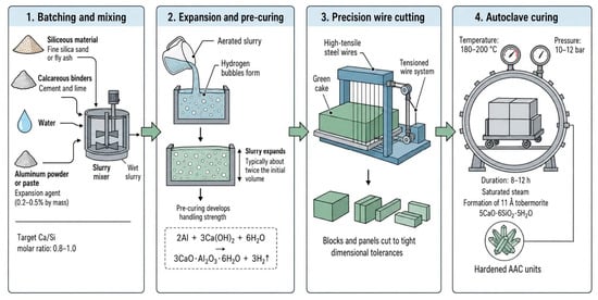
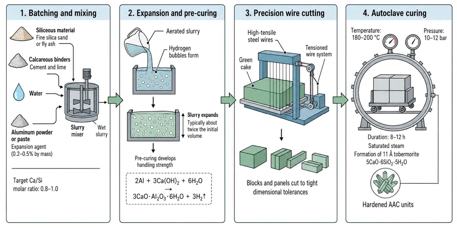
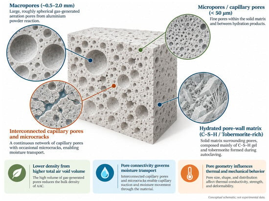
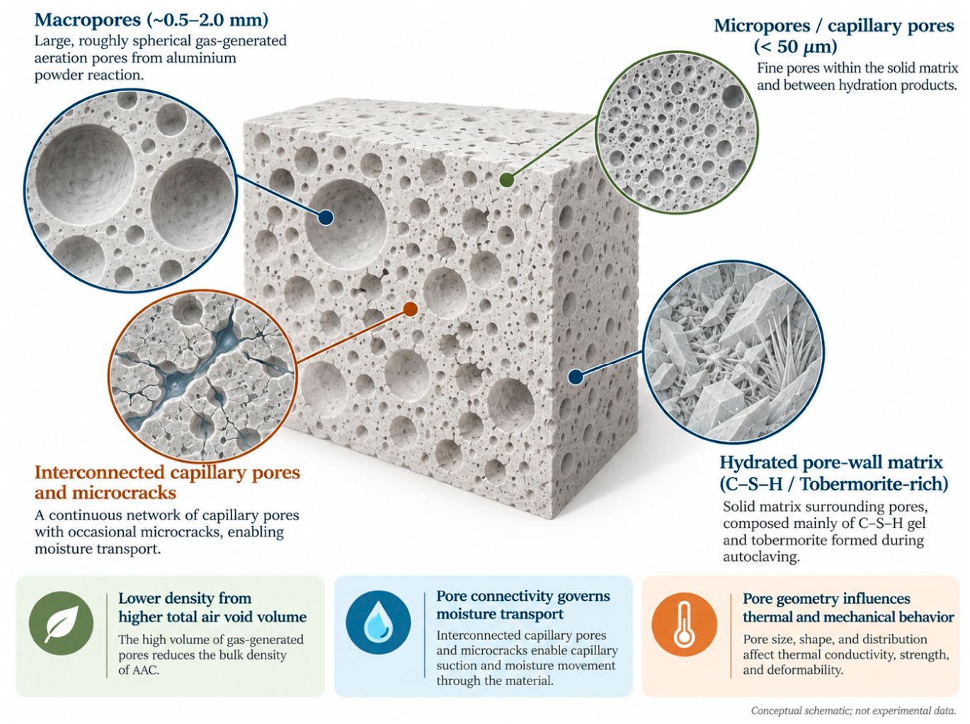
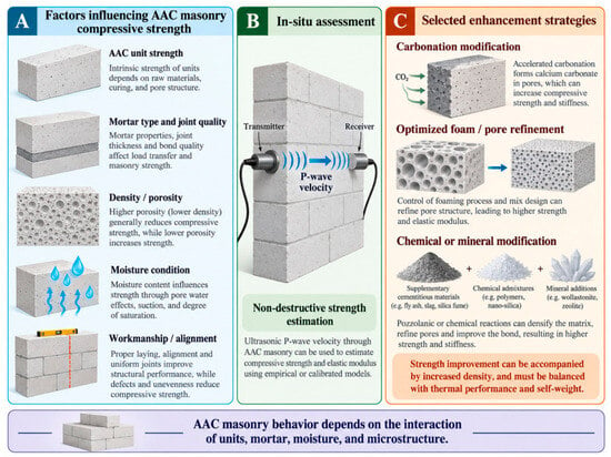
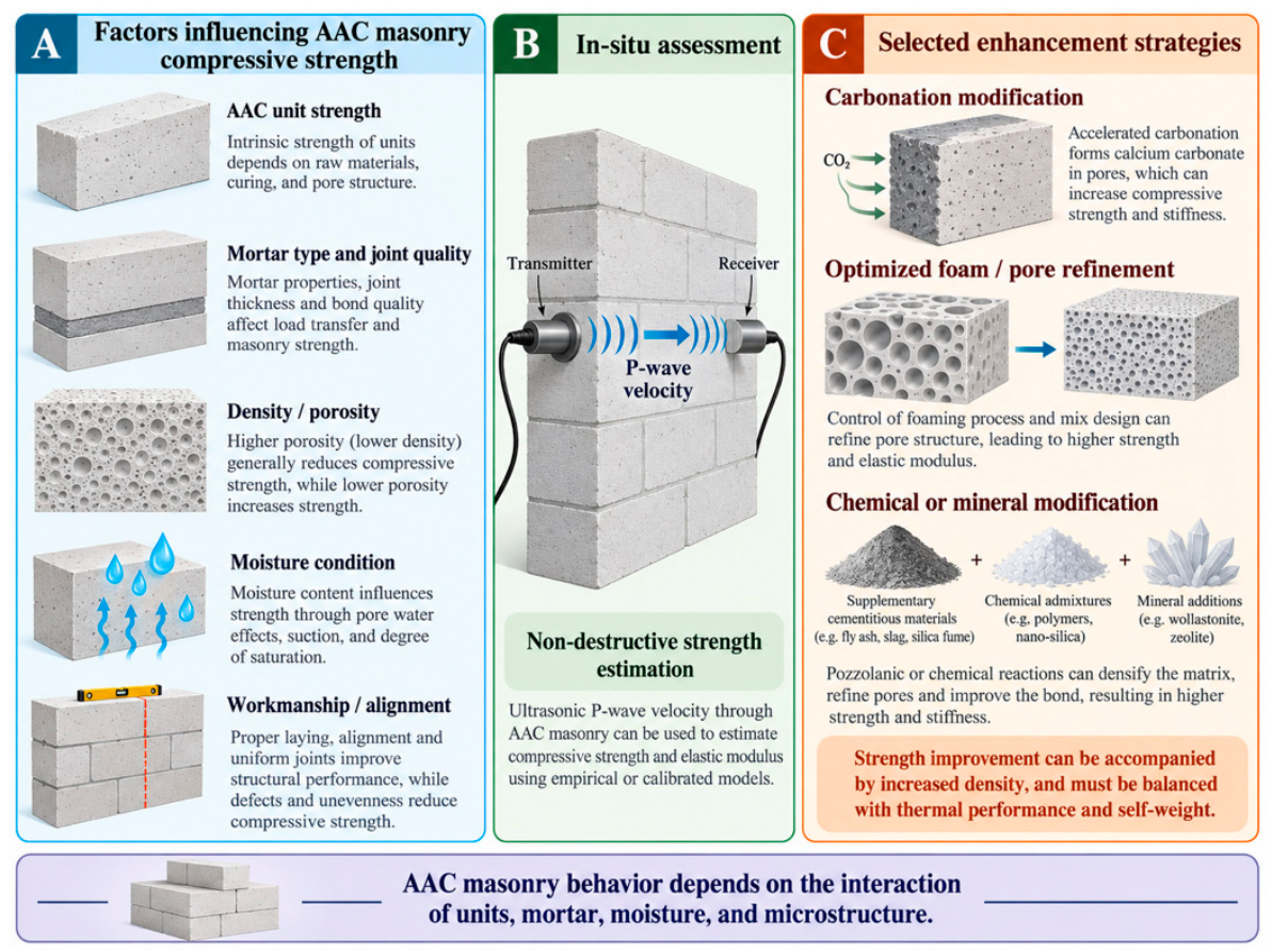
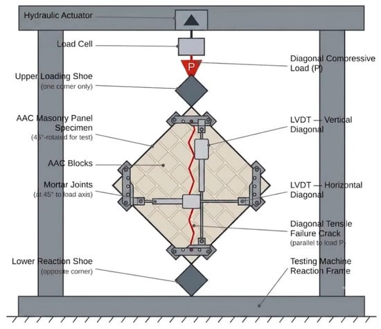
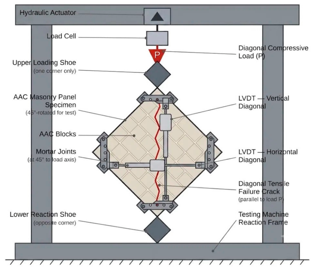
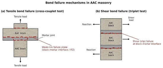
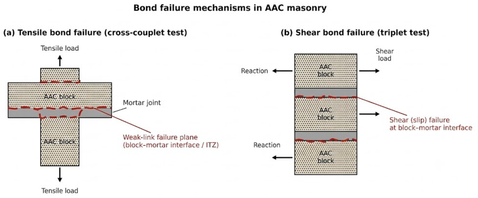
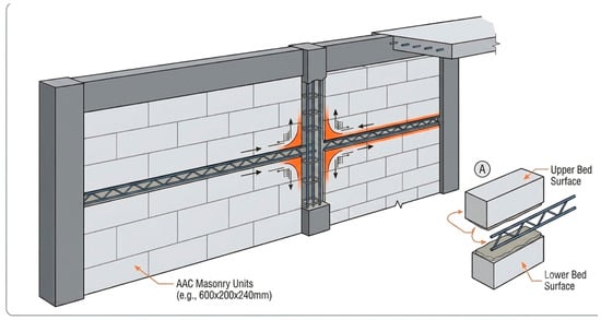
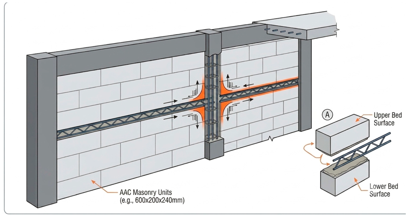
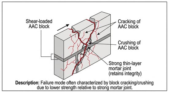
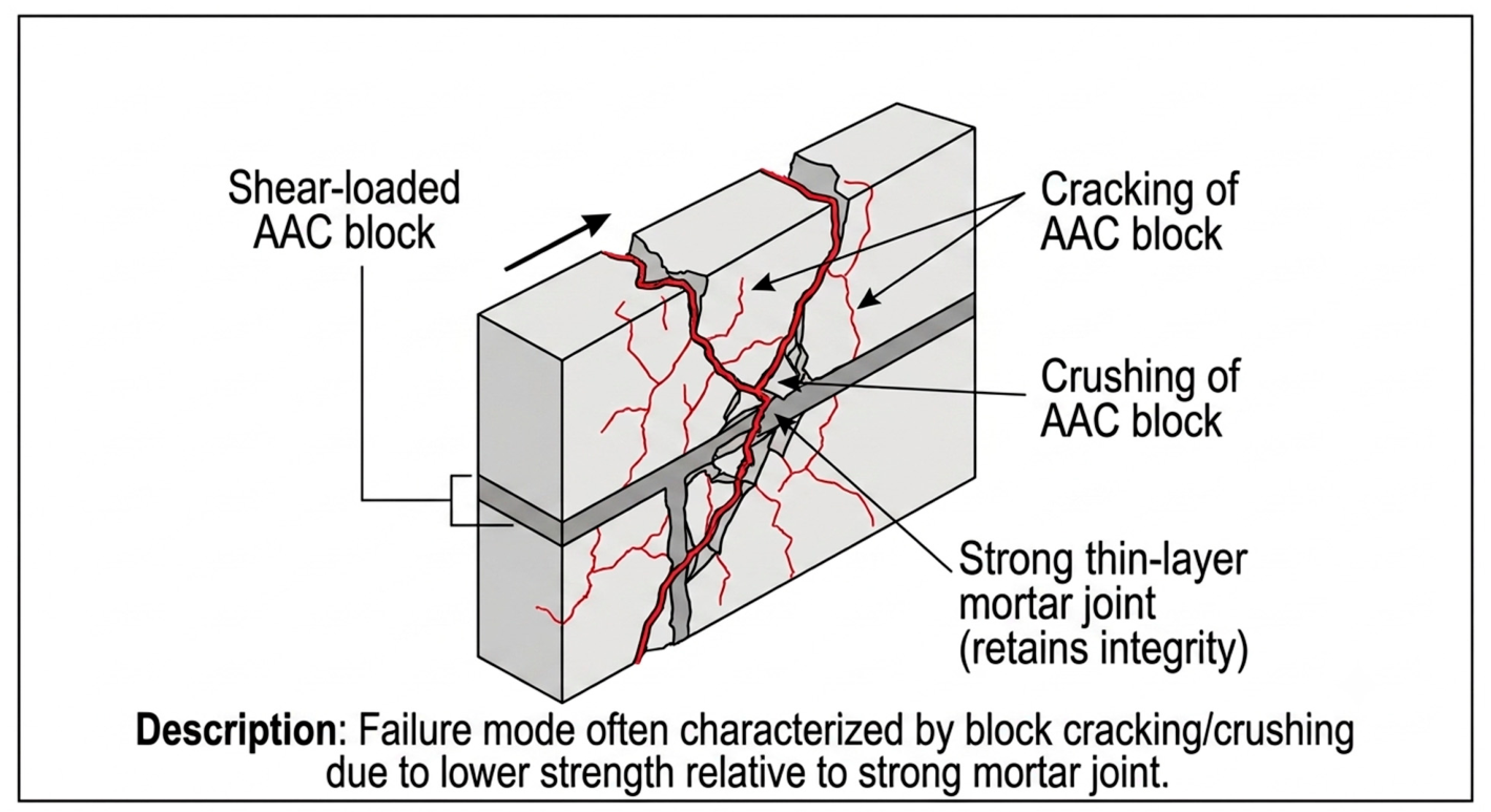
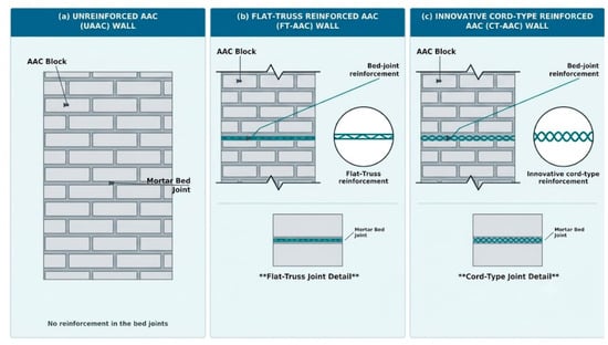
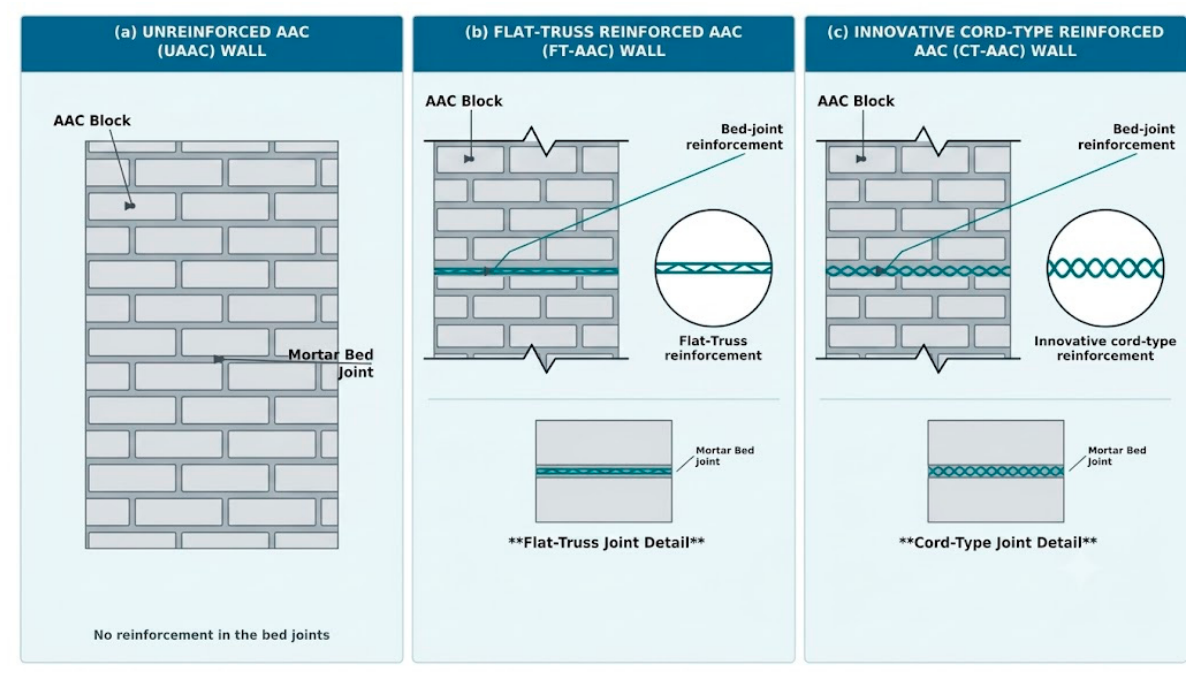
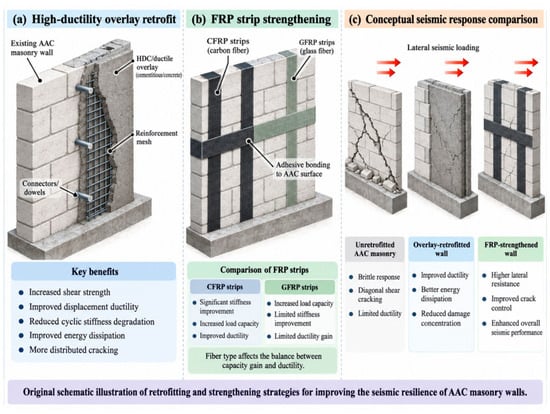
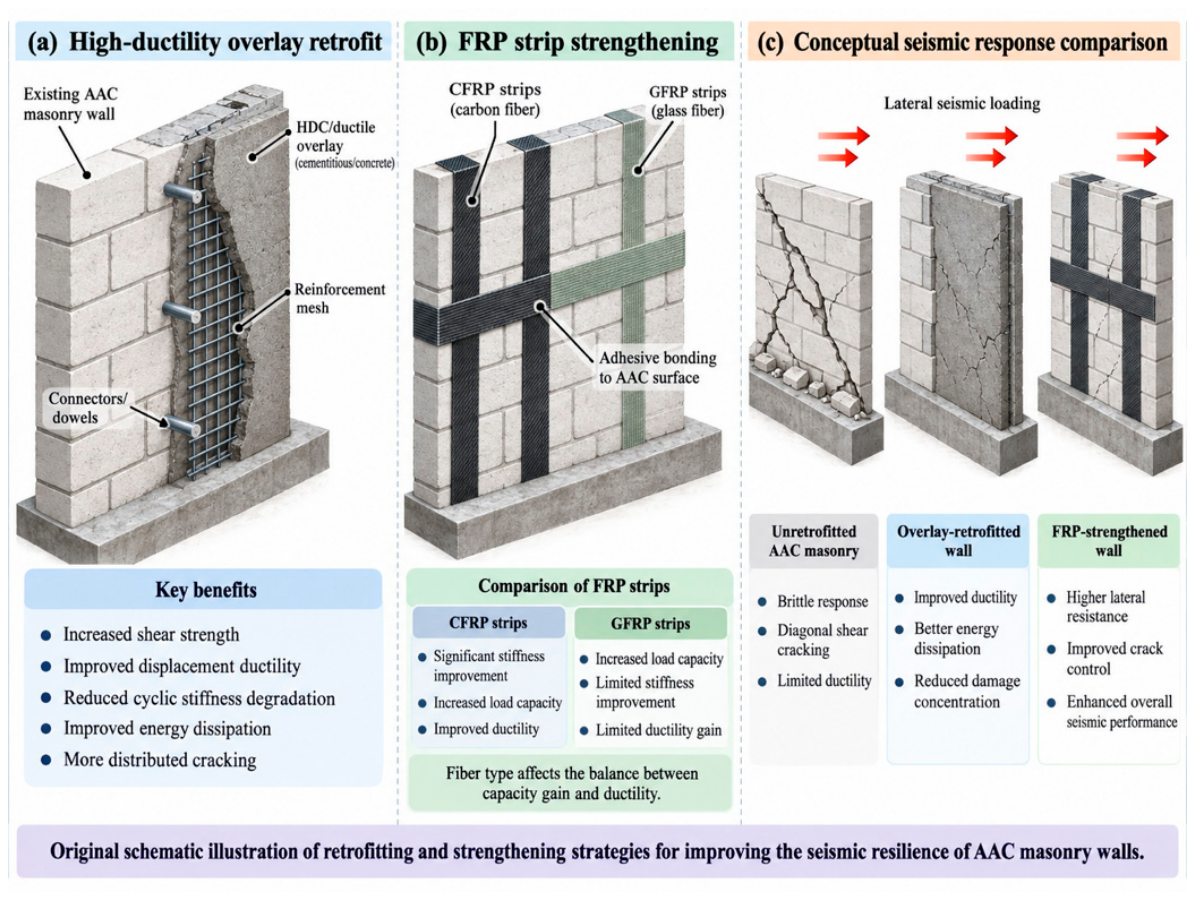
Disclaimer/Publisher’s Note: The statements, opinions and data contained in all publications are solely those of the individual author(s) and contributor(s) and not of MDPI and/or the editor(s). MDPI and/or the editor(s) disclaim responsibility for any injury to people or property resulting from any ideas, methods, instructions or products referred to in the content. |
© 2026 by the authors. Licensee MDPI, Basel, Switzerland. This article is an open access article distributed under the terms and conditions of the Creative Commons Attribution (CC BY) license.