


Abstract
Cold-formed steel (CFS) lipped channels are widely used in lightweight construction, yet their open, thin-walled geometry makes them highly vulnerable to torsion-driven instability and premature buckling under bending. To address this limitation, this study introduces an innovative riveted Delta-Channel concept that partially “closes” the section, shortens free edges where buckling initiates, and increases torsional rigidity. Full-scale four-point bending tests were performed on nine specimens (three Delta sections and six lipped channels), supported by nonlinear finite element (FE) models developed in ABAQUS. Across comparable geometries, Delta sections delivered a 66–140% increase in peak load capacity and markedly improved deflection control. The developed FE models showed good agreement with the experimental results and successfully reproduced the observed flexural behaviour of the investigated sections. Despite a modest increase in material usage, the proposed Delta sections achieved substantially higher flexural capacities than comparable conventional lipped channel sections.
1. Introduction
Cold-formed steel (CFS) sections are widely used in modern structural engineering because of their high strength-to-weight ratio, ease of fabrication, dimensional accuracy, recyclability, and cost efficiency. Unlike hot-rolled steel members, CFS sections are manufactured by forming thin steel sheets at room temperature into various structural profiles without the application of heat treatment. Due to these advantages, cold-formed steel members are extensively utilized in industrial sheds, storage systems, roof trusses, wall framing systems, purlins, and prefabricated buildings [1,2,3]. Recent advancements in lightweight structural systems and modular construction have further increased the demand for efficient cold-formed steel structural members [4].
Despite their structural and economic benefits, cold-formed steel sections are highly susceptible to instability-related failures because of their thin-walled geometry and high width-to-thickness ratios. The structural behavior of these members is usually governed by local, distortional, and global buckling modes, which may occur individually or interact simultaneously under loading conditions [5,6]. Local buckling typically occurs in individual plate elements such as webs and flanges, while distortional buckling involves deformation of the flange–lip assembly accompanied by rotational displacement at the flange–web junction. Global buckling, on the other hand, affects the member as a whole and includes flexural, torsional, and flexural–torsional instability modes [7,8]. Under flexural loading, the interaction between local and distortional buckling of the compression elements and global instability associated with torsional deformation can strongly influence the ultimate capacity of open thin-walled sections. The susceptibility to these instability modes is particularly important for lipped-channel beams because their open cross-section provides limited resistance to torsional deformation [9,10,11,12].
Among the various cold-formed steel profiles, lipped channel sections are one of the most commonly used structural shapes because of their manufacturing simplicity and practical applicability. However, conventional lipped channel sections possess open cross-sectional geometry with relatively low torsional rigidity, making them highly vulnerable to lateral–torsional buckling and twisting under flexural loading [13]. Previous studies have shown that the open geometry of channel sections causes instability to initiate near the free edges of the flanges and lips, significantly reducing their load-carrying capacity and structural efficiency [14,15]. Furthermore, loading eccentricity relative to the shear center can intensify torsional effects and accelerate premature buckling failure [16]. Recent experimental and numerical work has further demonstrated the importance of cross-sectional configuration for the flexural response of channel beams. Li and Young [17] conducted 16 four-point bending tests on unstiffened and edge-stiffened channel sections and subsequently developed a validated nonlinear FE model for a broader parametric study. Their results showed that edge stiffening can substantially alter the governing buckling response and the accuracy of conventional DSM predictions. Previous experimental and numerical investigations have therefore examined several approaches for improving the stability and flexural performance of thin-walled channel sections. These approaches have included modification of flange and lip geometry, introduction of intermediate web or edge stiffeners, and assembly of multiple cold-formed components to increase sectional rigidity. However, the effectiveness of these approaches depends strongly on the location, configuration, and continuity of the stiffening elements, as well as on their influence on local and distortional buckling modes.
To improve the structural performance of cold-formed steel sections, numerous researchers have investigated the use of flange stiffeners, intermediate web stiffeners, built-up sections, and modified cross-sectional geometries. Manikandan et al. [18] investigated the distortional buckling behaviour of lipped-channel sections incorporating different web-stiffener configurations and demonstrated the influence of stiffener arrangement on the instability response. Zhang and Young [19] examined built-up cold-formed steel sections incorporating edge stiffeners, showing the potential of sectional modification to improve structural performance. Similarly, Faridmehr et al. [20] investigated stiffened C-sections and demonstrated that modifications to the cross-sectional configuration can alter the buckling response and strength of thin-walled members. More recently, Rezaeian et al. investigated the flexural capacity of stacked built-up cold-formed steel sections assembled from lipped channels. Their parametric study considered different numbers of channel components and cap-plate configurations, demonstrating the influence of sectional configuration and closure on the flexural capacity of built-up members [21]. Similarly, Maizi et al. [22] investigated novel closed built-up cold-formed steel sections under flexural loading using validated nonlinear FE models. Their study demonstrated that sectional configuration and screw spacing influence the flexural response and that existing DSM provisions may not accurately predict the strength of such unconventional built-up sections. Wang et al. [23] examined gapped back-to-back built-up CFS beams assembled using discontinuous connecting plates and bolts under four-point bending. Their numerical investigation showed that connection arrangement, gap dimensions, and beam geometry can significantly affect the flexural response and lateral–torsional buckling behaviour of built-up members. Hancock et al. [7] demonstrated that distortional buckling behavior can be significantly influenced by sectional geometry and edge stiffening arrangements. Similarly, Young and Rasmussen [24] demonstrated the sensitivity of cold-formed channel members to their cross-sectional and stability characteristics through experimental testing. Manikandan and Arun [25] investigated partially closed stiffened cold-formed steel channel sections formed using spacer plates connected by self-tapping screws. Their experimental and numerical results showed that partial closure increased sectional torsional rigidity and stiffness and altered the governing buckling response compared with the corresponding open sections. More recently, Ma et al. [26] investigated the flexural–torsional behaviour of built-up cold-formed steel beams with different open and closed cross-sectional configurations. Their FE study accounted for discrete fasteners, contact interactions and geometric and material nonlinearities, demonstrating that sectional configuration and connection characteristics can influence the governing buckling mode and ultimate strength. Recent investigations have also focused on optimized and partially closed cold-formed steel sections to reduce torsional deformation and delay instability failures [27].
In parallel with experimental investigations, numerical methods such as the Finite Strip Method (FSM), Direct Strength Method (DSM), and nonlinear Finite Element Analysis (FEA) have become important tools for predicting the structural response of cold-formed steel members [28,29,30]. Recent studies have also demonstrated the effectiveness of nonlinear finite element modelling for validating the design provisions and buckling behaviour of cold-formed steel flexural members. Khan et al. validated the American Iron and Steel Institute (AISI) Direct Strength Method for cold-formed steel channel beams using ABAQUS-based nonlinear finite element analysis and reported good agreement between numerical predictions and design methodologies, highlighting the capability of FE modelling in accurately capturing buckling and flexural response of thin-walled steel members [31,32]. The Direct Strength Method proposed by Schafer [33] enabled efficient prediction of local and distortional buckling strength using elastic buckling solutions. Moreover, nonlinear finite element analysis using ABAQUS has been extensively employed to simulate post-buckling behavior, geometric imperfections, material nonlinearity, and failure mechanisms of cold-formed steel members with high accuracy [34].
Although previous studies have investigated stiffened, built-up, and partially closed cold-formed steel sections, the structural behaviour of geometrically modified riveted Delta-type sections under flexural loading remains insufficiently understood. Furthermore, validated nonlinear finite element investigations combined with full-scale experimental testing on such innovative sections are still scarce in the available literature. Addressing this research gap is essential for developing lightweight cold-formed steel beam systems with enhanced structural stability and improved load-carrying efficiency suitable for modern construction applications.
Therefore, the main objective of this study is to quantitatively evaluate the structural effectiveness of an innovative riveted Delta-Channel cold-formed steel section in comparison with conventional lipped channel sections. The effectiveness of the proposed configuration is assessed using four quantitative performance indicators: (i) the percentage increase in ultimate load capacity relative to a geometrically comparable conventional lipped channel section; (ii) the reduction in mid-span deflection at ultimate load; (iii) the structural efficiency, evaluated by relating the percentage increase in flexural capacity to the corresponding percentage increase in specimen weight; and (iv) the accuracy of the nonlinear finite element model, quantified using the mean and coefficient of variation of the experimental-to-FE ratios for ultimate load and mid-span deflection. Full-scale four-point bending tests are combined with nonlinear finite element simulations in ABAQUS to evaluate the flexural response, deformation characteristics, buckling behaviour, and failure mechanisms of the investigated sections.
To achieve the stated objectives, the paper is organized as follows:
- -
- Section 2 describes the experimental program, including the material properties, specimen fabrication, geometric configurations of the conventional lipped channel and proposed Delta-Channel sections, test setup, instrumentation, loading arrangement, and four-point bending procedure adopted in this study.
- -
- Section 3 presents the development of the nonlinear finite element models in ABAQUS, including the modelling assumptions, material constitutive laws, meshing strategy, element selection, boundary and loading conditions, interaction definitions, geometric imperfections, and nonlinear analysis procedures adopted for the simulation of the investigated specimens.
- -
- Section 4 presents and discusses the results obtained from the experimental and numerical investigations. The finite element models are first validated against the experimental results, followed by an assessment of flexural capacity enhancement, structural efficiency, and the buckling and failure behaviour of the investigated sections. Comparisons between the conventional lipped channel and proposed Delta-Channel sections are also presented and discussed.
- -
- Section 5 summarizes the principal findings of the study and presents the major conclusions regarding the effectiveness of the proposed riveted Delta-Channel section in improving the structural performance of cold-formed steel beams.
2. Materials and Methods
To evaluate the structural effectiveness of the proposed Delta-Channel section, an experimental investigation was carried out on full-scale cold-formed steel beam specimens subjected to four-point bending. The experimental program was designed to examine the influence of the modified cross-sectional geometry on flexural stiffness, load-carrying capacity, torsional response, and buckling behaviour in comparison with conventional lipped channel sections.
The proposed Delta-Channel section was developed by introducing inclined plate elements into the conventional lipped channel configuration to form a partially closed section. This geometric modification was intended to enhance torsional rigidity and reduce the free-edge lengths where local and distortional buckling generally initiate in thin-walled cold-formed steel members. To assess the effectiveness of the proposed configuration, both Delta-Channel and conventional lipped channel sections with comparable geometric dimensions were experimentally investigated.
A total of nine specimens were tested, comprising three Delta-Channel sections and six conventional lipped channel sections fabricated from commercially available galvanized steel sheets. The three Delta-Channel configurations were selected to provide a proof-of-concept assessment of the proposed partially closed geometry while examining two key geometric variables within the available experimental programme: sheet thickness (0.7 and 1.0 mm) and flange width (50.0 and 62.5 mm). Each Delta-Channel configuration was tested once; therefore, the experimental programme does not permit a statistical assessment of specimen-to-specimen variability or repeatability. Instead, the Delta-Channel tests were intended to establish the feasibility and structural response of the proposed configuration and to provide benchmark results for validation of the nonlinear finite element models. Geometrically comparable conventional lipped channel specimens were tested to provide a direct basis for evaluating the relative flexural performance of the proposed configuration, while additional conventional specimens with increased thickness were included to provide supplementary information on the influence of section thickness on flexural behaviour.
All specimens were tested under monotonic loading using a four-point bending configuration. The experimental observations focused on ultimate load capacity, load–deflection response, deformation characteristics, torsional behaviour, and the development of local, distortional, and global buckling modes. The experimental results obtained from the bending tests were subsequently used to validate the nonlinear finite element models developed in ABAQUS v2021.
2.1. Material Properties
The specimens investigated in this study were fabricated from commercially available galvanized steel sheets obtained from the local market. Tensile coupon tests were conducted in accordance with ASTM A370 [35] to determine the mechanical properties of the steel used for both the experimental and numerical investigations.
Three sheet thicknesses, namely 0.7 mm, 1.0 mm, and 1.5 mm, were considered in the investigation. Standard dog-bone tensile specimens were prepared from the flat portions of the steel sheets and tested using a universal testing machine. The engineering stress–strain relationships obtained from the coupon tests were subsequently used to define the material constitutive behaviour in the finite element models.
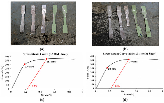
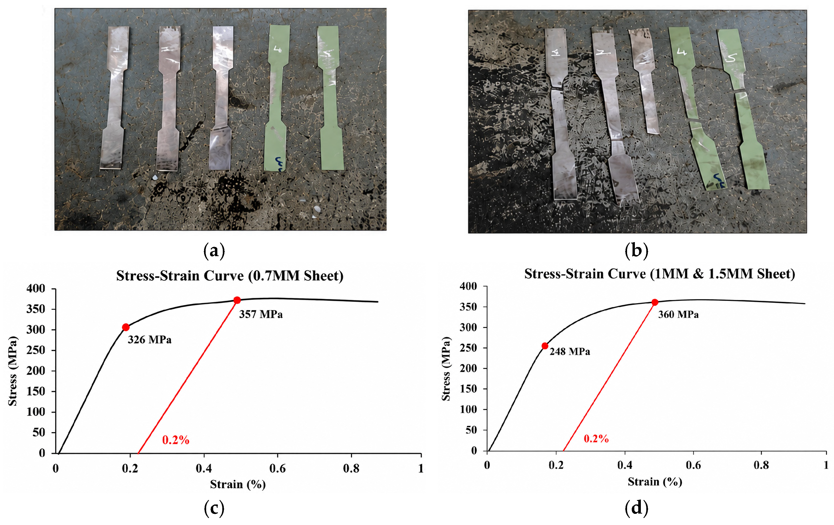
The average yield stress and ultimate tensile strength of the 0.7 mm sheets were approximately 326 MPa and 357 MPa, respectively (Table 1). For the 1.0 mm and 1.5 mm sheets, the corresponding average yield stress and ultimate tensile strength were approximately 288 MPa and 360 MPa. An elastic modulus of 200 GPa and Poisson’s ratio of 0.3 were adopted for all numerical simulations. Figure 1 presents the tensile coupon specimens and the corresponding experimental stress–strain responses used to characterise the steel material. Figure 1a shows the tensile specimens prepared from the investigated steel sheets, while Figure 1b–d present the corresponding material-test and stress–strain information for the tested material configurations. The different specimen colours shown in Figure 1a are used only to distinguish the individual coupon specimens and do not indicate a difference in the material constitutive model. The stress–strain curves demonstrate the elastic and subsequent nonlinear response obtained from the tensile tests and were used to define the material behaviour adopted in the FE models.
Table 1.
Mechanical properties of the investigated steel sheets.
Figure 1.
Tensile coupon testing and engineering stress–strain curves for the investigated steel sheets. (a) Coupons for 0.7 mm Sheet; (b) Coupons for 1 mm and 1.5 mm Sheet; (c) Stress-Strain Curve for 0.7 mm; (d) Stress-Strain Curve for 1 mm and 1.5 mm.
2.2. Specimen Geometry
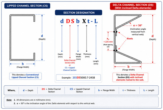
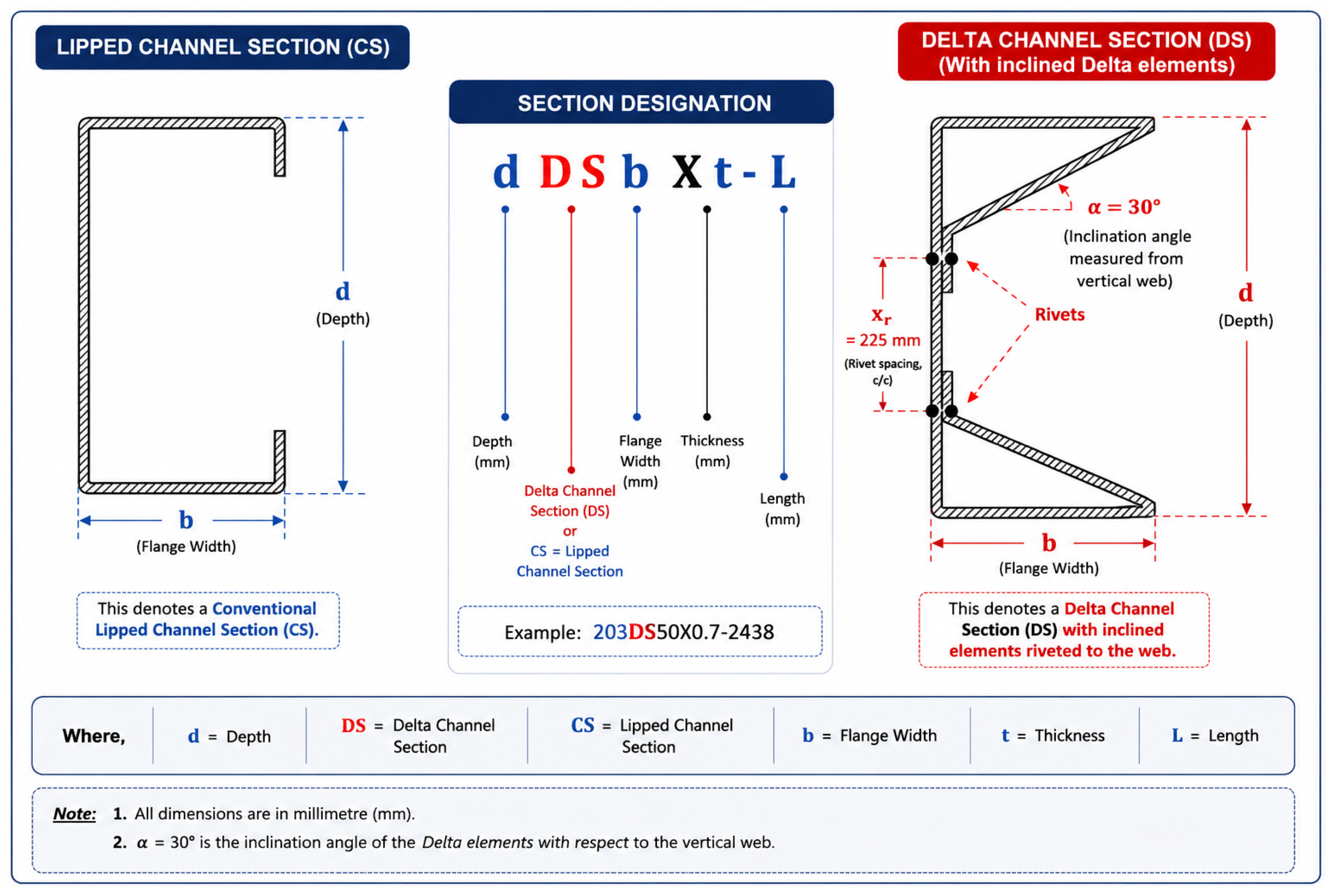
Two different cold-formed steel cross-sectional configurations were investigated in this study, namely conventional lipped channel sections and the proposed riveted Delta-Channel sections. The Delta-Channel configuration was developed by forming the required Delta-shaped elements from a galvanized steel sheet through bending operations and subsequently assembling them with the channel components using riveted connections, resulting in a partially closed cross-section. The configuration was therefore conceived as a formed cold-rolled steel system rather than simply as a conventional lipped channel with externally attached reinforcement plates. This geometric modification was intended to enhance torsional rigidity and reduce the free-edge lengths that typically govern local and distortional buckling in thin-walled members. The geometric configurations of the investigated sections are shown in Figure 2. The inclined Delta elements were arranged at an angle of approximately α = 30° with respect to the vertical web. The elements were connected to the web using rivets at a centre-to-centre spacing of xr = 225 mm. The principal geometric parameters and the inclination angle are illustrated in Figure 2.
Figure 2.
Geometric configurations of the investigated sections: (Left) conventional lipped channel section; (Right) proposed riveted Delta-Channel section.
The specimen designation follows the format dCSbXt-L or dDSbXt-L, where d represents the section depth, CS and DS denote lipped channel and Delta-Channel sections, respectively, b is the flange width, t is the base steel thickness, and L is the specimen length. The geometric details and specimen designations of the tested sections are summarized in Table 2.
Table 2.
Geometric details of the tested specimens.
The 1.5 mm conventional lipped-channel specimens were tested at a shorter length of 1829 mm, whereas the remaining specimens had a length of 2438 mm; therefore, the results of the 1.5 mm specimens are considered separately when assessing the influence of thickness.
2.3. Specimen Fabrication
The conventional lipped channel specimens were procured from commercially available galvanized cold-formed steel sections. The Delta-Channel specimens were fabricated and assembled prior to testing using riveted connections. The Delta-Channel components were connected using 5 mm diameter headed rivets manufactured from the same material as the steel sections. The rivets were arranged at a centre-to-centre spacing of 225 mm, with an edge distance of 100 mm. The diameter of the pre-drilled holes was 5 mm, corresponding to the nominal rivet diameter. During testing, no noticeable slip, significant bearing deformation, or local damage at the riveted connections was observed prior to failure of the specimens. The riveted connections remained intact throughout the loading process and did not govern the observed failure modes.
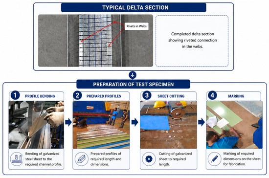
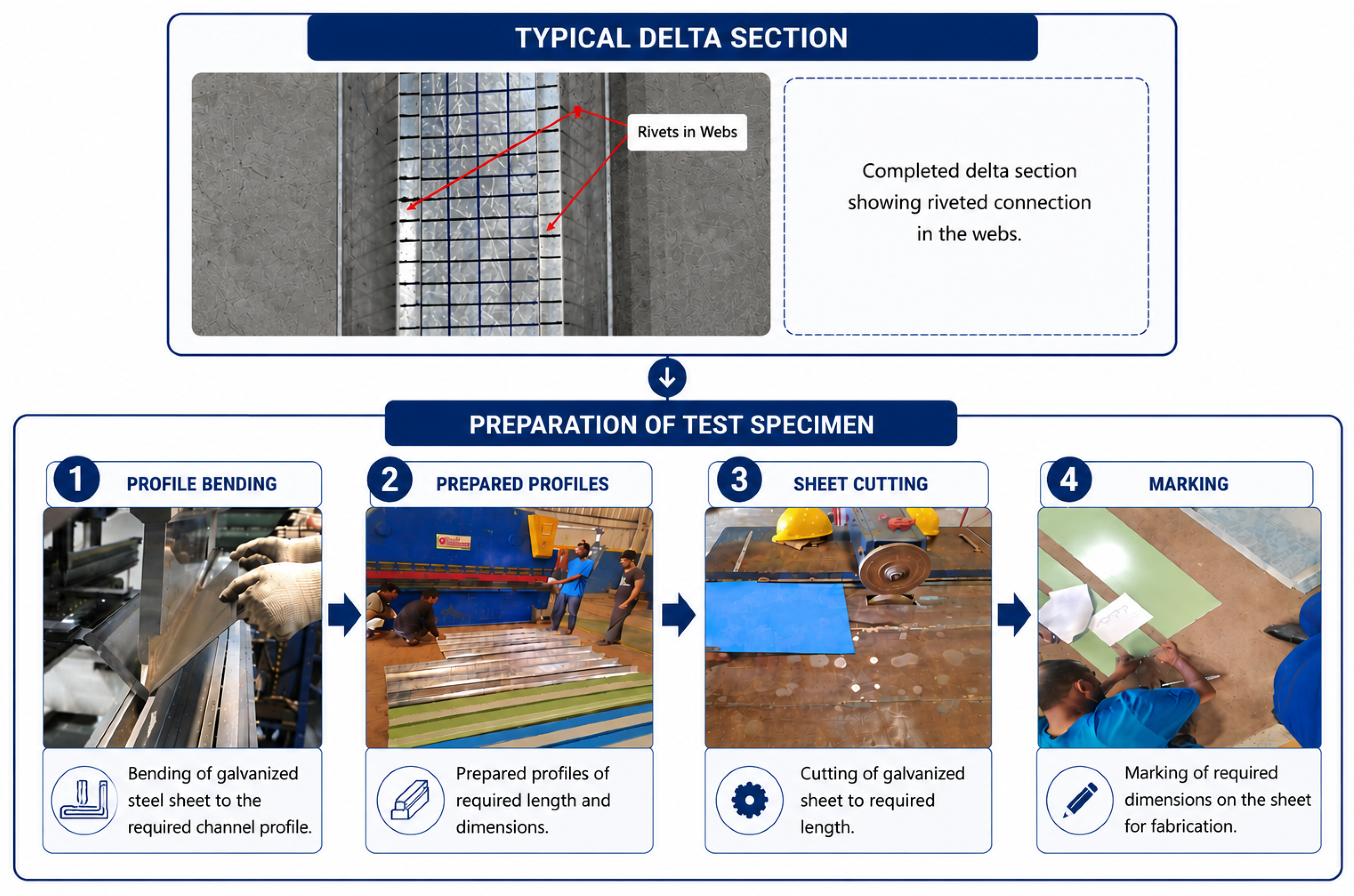
The fabrication of the Delta-Channel specimens involved a sequence of profile preparation, sheet cutting, marking, forming, and assembly operations, as illustrated in Figure 3. First, the galvanized steel sheet was bent to produce the required channel profile geometry. The formed profiles were then prepared to the required dimensions and length, while separate galvanized steel sheet elements were cut to the dimensions required to form the Delta components. The required locations for fabrication and assembly were subsequently marked on the prepared components to ensure consistent positioning. The Delta elements were then positioned within the channel profile to form the intended partially closed cross-section and were connected to the web using riveted connections. Following assembly, the completed specimens were inspected to verify dimensional consistency, alignment, and the integrity of the riveted connections before being prepared for four-point bending tests.
Figure 3.
Fabrication process and assembly of the proposed Delta-Channel section.
Following fabrication, all specimens were inspected to ensure dimensional consistency and proper alignment before testing. The completed specimens were subsequently prepared for experimental evaluation under four-point bending.
2.4. Experimental Setup
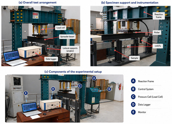
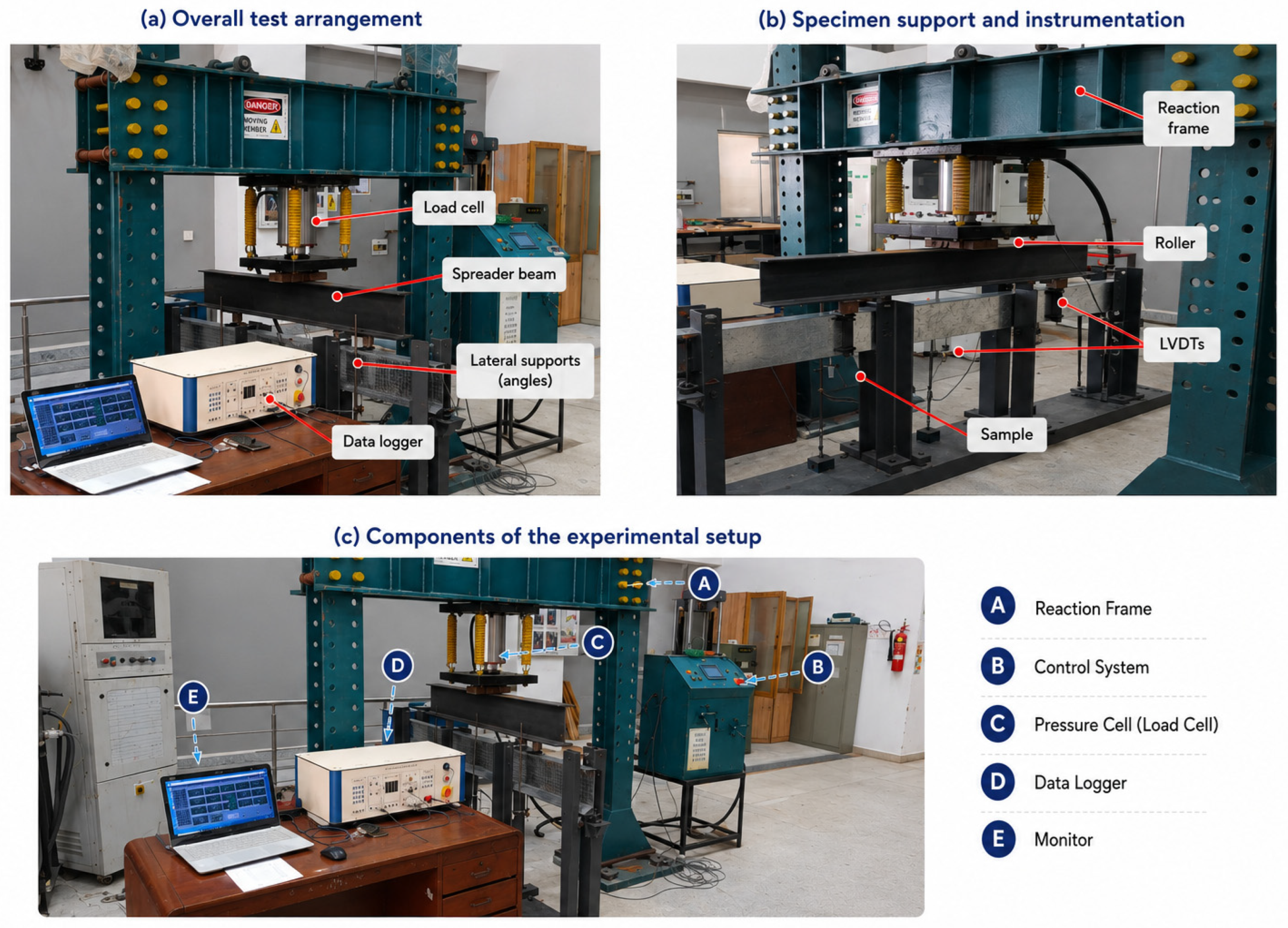
All specimens were tested under four-point bending using a hydraulic loading frame, as shown in Figure 4. The load was applied through a spreader beam to create two symmetrically positioned concentrated loads, spaced 610 mm apart, thereby establishing a constant moment region between the loading points. The distance from each support to the nearest loading point was 914 mm. The specimens were simply supported at both ends and loaded monotonically until failure. Four-point bending was selected to provide a constant-moment region between the two loading points, allowing the flexural response of the specimens to be evaluated under a controlled bending condition with reduced influence of a concentrated load at a single location. This arrangement also enabled the development and observation of local deformation and buckling within the constant-moment region, providing a consistent basis for comparing the proposed Delta-Channel sections with the conventional lipped-channel specimens.
Figure 4.
Experimental setup for four-point bending tests: (a) overall test arrangement; (b) specimen support and instrumentation; and (c) components of the loading and data acquisition system.
The specimens were simply supported using roller supports located 5 mm from each end. Accordingly, the clear spans were 2438 mm for the nominal 2448 mm specimens and 1819 mm for the nominal 1829 mm specimens. To restrain undesirable lateral–torsional movement while allowing the intended flexural response to develop, steel angle sections were fixed on both sides of the specimens at locations 30 mm inside each support. The tests were conducted under displacement-controlled loading, with a displacement increment of 0.05 mm, corresponding to an approximate load increment of 0.185 kN. The ultimate load and corresponding deformation were continuously monitored during each test. For the purposes of this study, failure was defined as the attainment of the peak load followed by a reduction in the load-carrying capacity.
The applied load was measured using a calibrated unidirectional load cell with a maximum capacity of 50 tons, integrated within the loading system. The load measurement system was calibrated using a traceable digital load cell, with calibration checks performed over the 100–900 kN range. The calibration report indicated an average error factor of −0.37%, with individual calibration errors ranging from −2.02% to +0.66%. Vertical deflections were monitored using three Soway SDVB20-25A (Soway Tech Limited, Shenzhen, China) linear variable differential transformers (LVDTs), with one positioned at mid-span and one directly beneath each loading point. The LVDTs have a nominal measurement range of 0–25 mm and, according to the manufacturer’s specifications for the SDVB20 series, a linearity error of ±0.25% of full scale. A 16-channel data logger with a ±10 V input range and 16-bit resolution was used for data acquisition. Prior to each test, the load cell and LVDTs were initialized through the data acquisition system to establish their zero reference readings before the application of load. The load and displacement data were continuously recorded through the computerized data acquisition system. The load cell was calibrated prior to the experimental programme, while the LVDTs were checked before each test for proper operation and stable zero readings. Accordingly, the instrumentation characteristics and calibration information provide the basis for assessing the accuracy of the measured load and displacement responses.
Throughout the testing program, the deformation patterns, buckling behaviour, and failure modes of the specimens were visually monitored and documented.
3. Finite Element Modelling
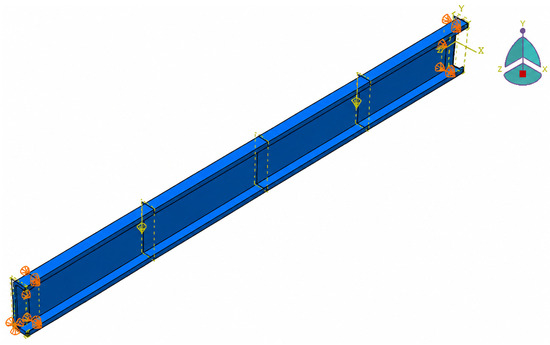
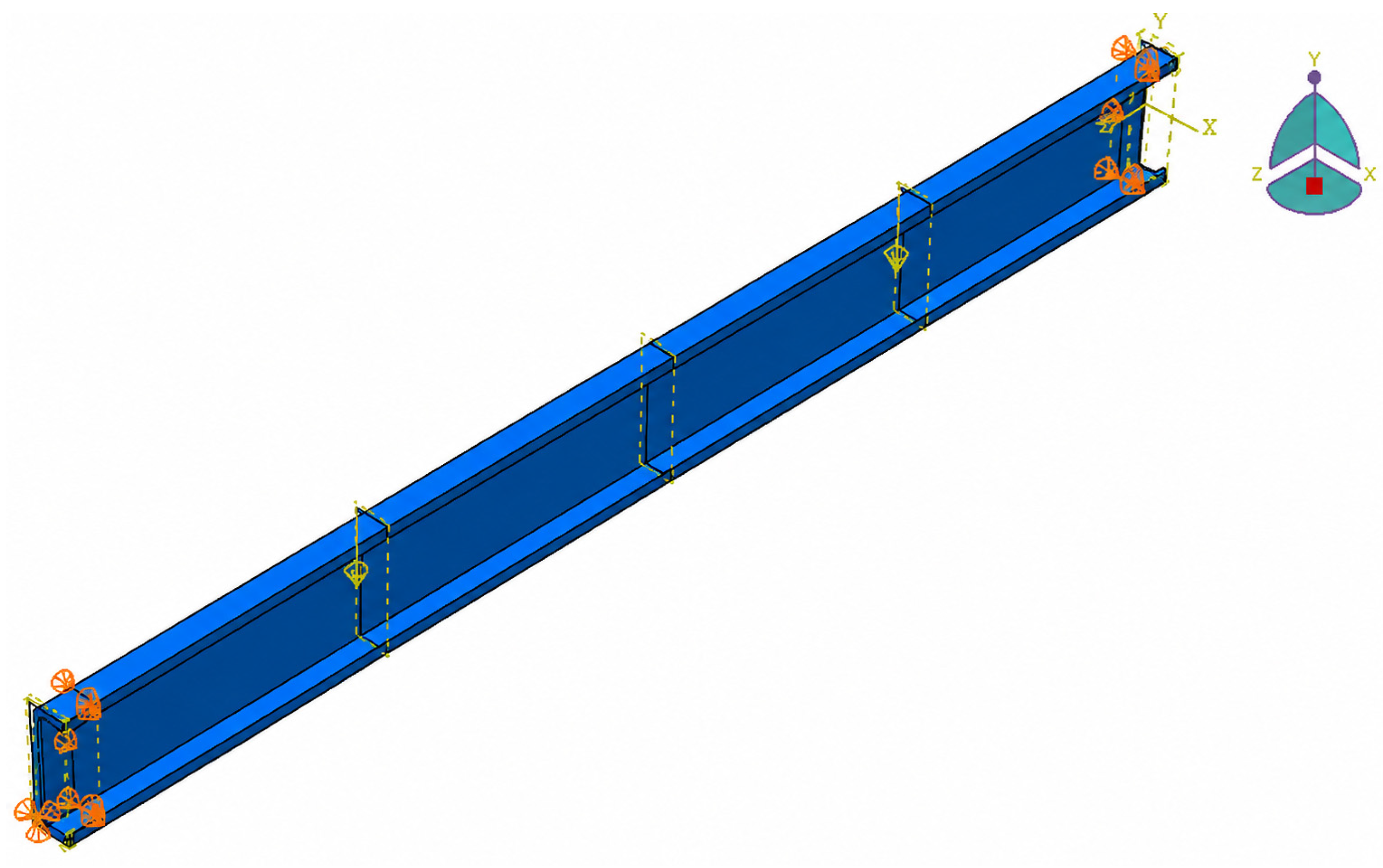
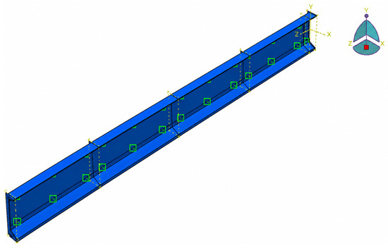
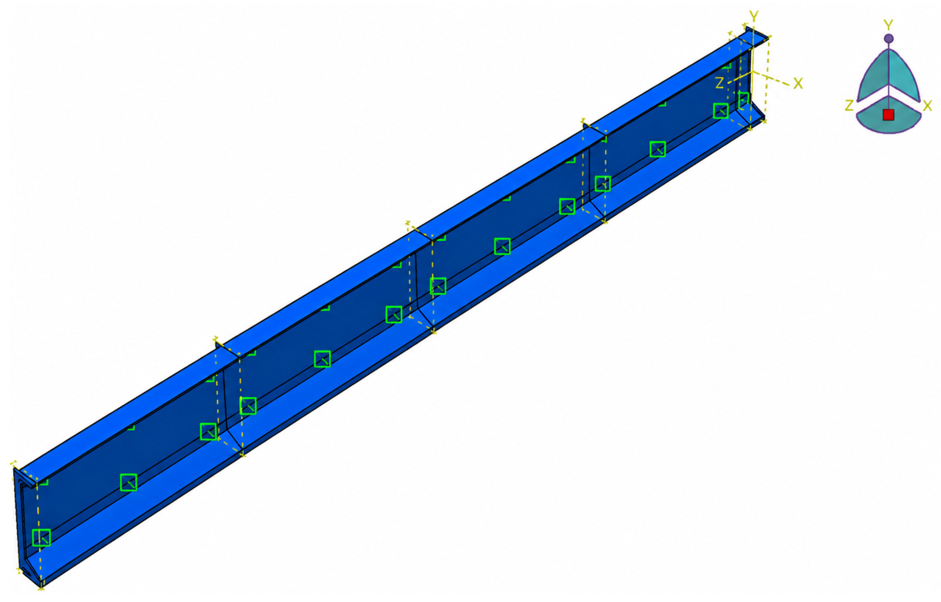
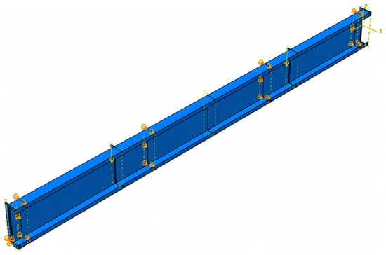
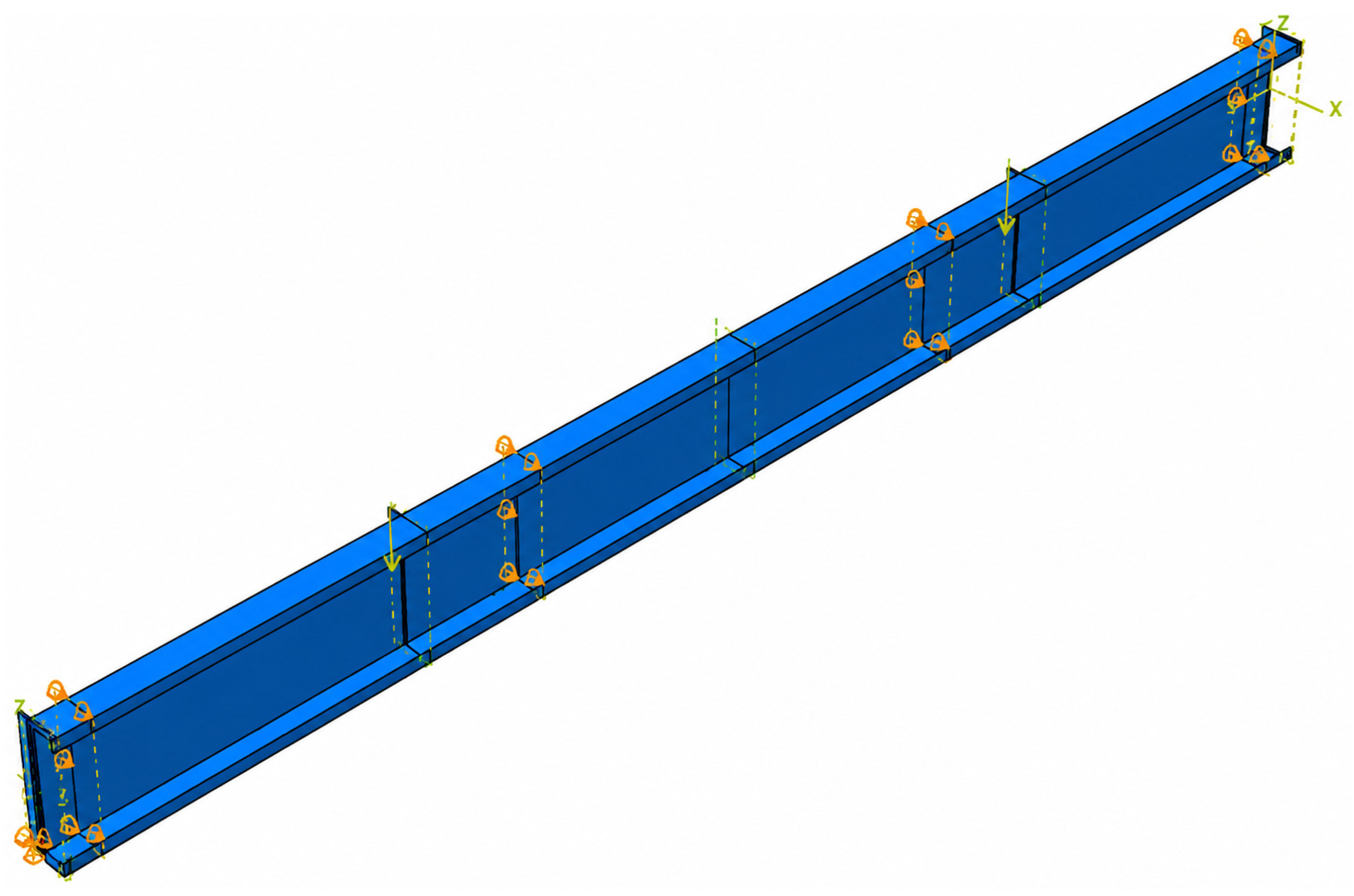
Advanced finite element modelling has become an effective tool for capturing nonlinear behaviour and validating structural response in steel systems, including cold-formed steel members and tubular steel connections [36,37,38,39,40,41]. Finite element (FE) models were developed in ABAQUS [34] to simulate the experimentally tested Delta-Channel and conventional lipped-channel specimens and to reproduce their flexural response, deformation behaviour, and failure modes under the four-point bending configuration. The numerical models were generated using the measured specimen dimensions and were configured to replicate the four-point bending arrangement adopted in the experimental program. The support and loading conditions adopted in the finite element models were identical to those used in the experimental program. The specimens were modelled under four-point bending with simply supported boundary conditions and two symmetrically applied concentrated loads, producing a constant moment region between the loading points. Intermediate lateral restraints were incorporated where required to replicate the experimental setup, as shown in Figure 5.
Figure 5.
FE model boundary conditions and load application arrangement.
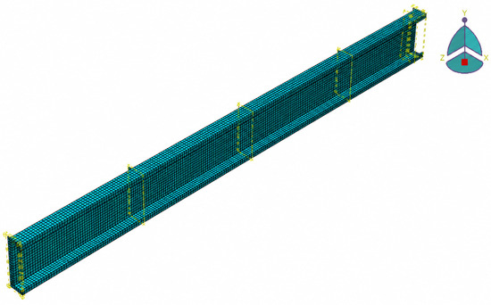
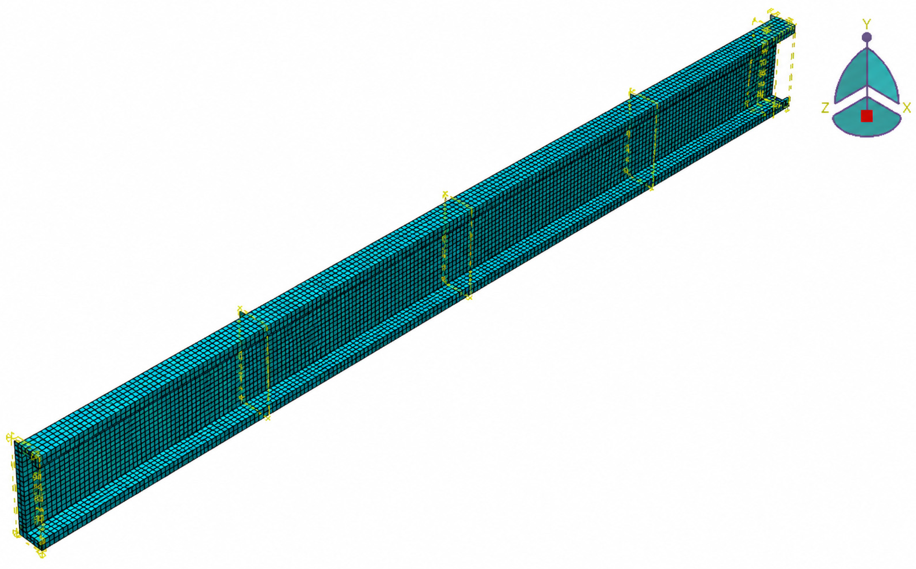
The steel sections were modelled using four-node reduced integration shell elements (S4R), which are well suited for simulating the behaviour of thin-walled cold-formed steel members. Elastic–plastic material properties were assigned based on the coupon test results presented in Section 2.1. A Young’s modulus of 200 GPa and a Poisson’s ratio of 0.30 were adopted, while the experimentally obtained bilinear stress–strain relationships were used to define the nonlinear material response. The final mesh configuration employed in the analyses is shown in Figure 6.
Figure 6.
Finite Element Mesh.
The geometric imperfections were introduced using the first elastic buckling mode obtained from the eigenvalue analysis, with an imperfection amplitude of L/1000. For specimens for which the first eigenmode did not produce a representative deformation pattern, the next appropriate buckling mode was adopted.
The specimen ends were modelled as simply supported, while additional lateral restraints were introduced through hinge constraints to prevent rigid-body torsional motion while allowing the intended flexural and local buckling behaviour. The riveted connections between the overlapping shell components were represented using attachment points and constrained connector interactions. All three translational (U1, U2, U3) and three rotational (UR1, UR2, UR3) degrees of freedom were constrained at the connector locations, providing an idealized representation of the mechanical restraint provided by the rivets without explicitly modelling individual rivets.
The nonlinear analyses were performed using the modified Riks method, with an initial arc-length increment of 0.01, a maximum arc-length increment of 1.0, and a maximum of 150 increments; the maximum number of increments was increased to 200 where required for convergence.
A mesh convergence study was performed using element sizes of 5, 7.5, 10, 12.5, 15, and 20 mm. The predicted eigenvalue decreased from 2704.2 for the 20 mm mesh to 2303.1 for the 10 mm mesh, while further refinement to 5 mm resulted in an eigenvalue of 2219. The difference between the 10 mm and 5 mm meshes was approximately 3.79%, indicating that the solution was sufficiently converged at 10 mm. Accordingly, a 10 mm mesh was adopted for the subsequent analyses as a balance between numerical accuracy and computational efficiency.
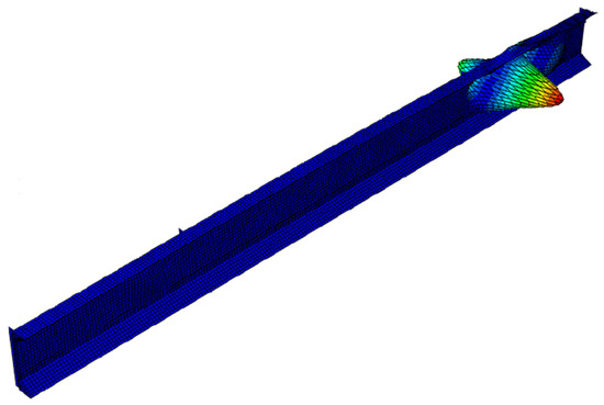
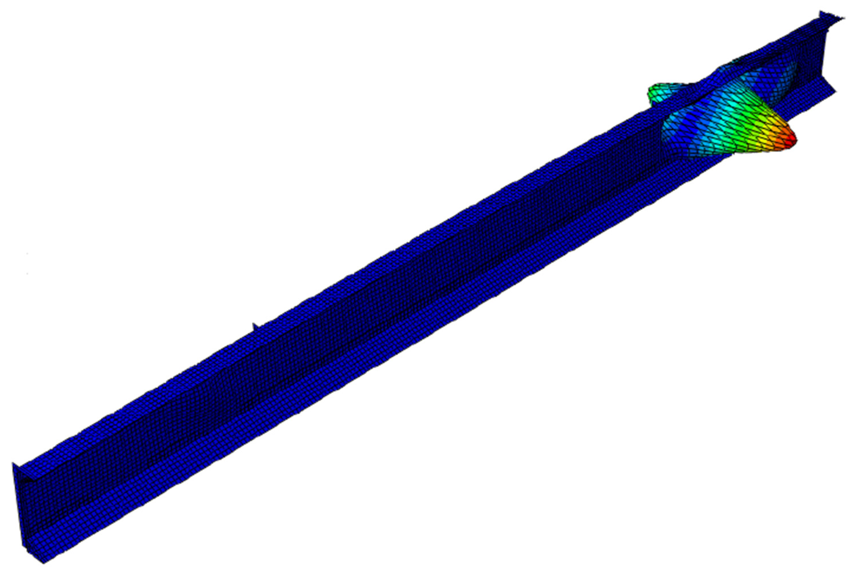
The analysis was performed in two sequential stages. Initially, a linear perturbation (eigenvalue buckling) analysis was conducted to determine the critical buckling modes of the investigated sections. Ten eigenvalues were extracted to ensure that all significant buckling modes were captured. The first eigen-buckling mode was subsequently introduced into the nonlinear model as an initial geometric imperfection to account for the unavoidable geometric imperfections present in cold-formed steel members. A representative eigen-buckling mode obtained from the analysis is presented in Figure 7.
Figure 7.
Buckling Mode Selected for Analysis.
Following the eigenvalue analysis, geometrically and materially nonlinear analyses were performed using the Static Riks method to capture the post-buckling response, ultimate flexural strength, and failure behaviour of the investigated sections. The adopted nonlinear solution strategy enabled the complete structural response to be traced beyond the peak load and into the post-peak region. For the Delta-Channel sections, the overlapping shell components were connected using face-to-face fastener interactions available in ABAQUS. Attachment points were defined at 225 mm intervals along the connection line to represent the riveted connections used in the experimental specimens. The spacing was selected to replicate the experimental specimen configuration and provide adequate force transfer between the connected shell components. The adopted interaction strategy ensured appropriate force transfer and compatibility of deformation between the connected shell surfaces, thereby enabling realistic simulation of the built-up Delta-Channel behaviour. The interaction definition adopted in the numerical models is illustrated in Figure 8.
Figure 8.
Modelling of riveted connections using face-to-face fastener interactions.
For the channel specimens requiring intermediate restraint, lateral supports were introduced at one-third of the specimen span from each end, consistent with the experimental setup, as shown in Figure 9.
Figure 9.
Intermediate Lateral Restraints (at L/3).
4. Results and Discussion
4.1. FE Model Validation
The developed finite element models were validated against the experimental results obtained from the four-point bending tests. Validation was carried out by comparing the ultimate load capacities and corresponding mid-span deflections at ultimate load for both the proposed Delta-Channel and conventional lipped channel sections. This comparison enabled the accuracy of the adopted modelling approach in predicting the flexural behaviour of cold-formed steel members to be assessed.
The numerical models incorporated the experimentally determined material properties, geometric dimensions, boundary conditions, loading arrangements, and geometric imperfections described in Section 2 and Section 3. The validation process focused on evaluating the ability of the models to reproduce the experimentally observed structural response, including load-carrying capacity and deformation behaviour.
Table 3 presents the comparison between the experimental and finite element ultimate load capacities of the investigated specimens. Good agreement was obtained between the experimental and numerical results, with Exp./FE ratios ranging from 0.94 to 1.22, a mean value of 1.07, and a coefficient of variation (CoV) of 0.09. The mean Exp./FE ratio of 1.07 and CoV of 0.09 indicate that the developed FE model provides reliable predictions of the flexural strength of both Delta-Channel and conventional lipped channel sections.
Table 3.
Comparison of experimental and finite element ultimate load capacities.
Table 4 compares the experimental and finite element mid-span deflections at ultimate load. The Exp./FE ratios ranged from 0.70 to 1.33, with a mean value of 1.13 and a CoV of 0.17. Although greater variability was observed in the displacement predictions compared with the ultimate load capacities, the numerical models generally reproduced the measured deformation response with acceptable accuracy. Overall, the close agreement obtained between the experimental and numerical results confirms the suitability of the adopted finite element modelling approach for investigating the flexural behaviour of the proposed Delta-Channel sections.
Table 4.
Comparison of experimental and finite element Mid-Span Deflections.
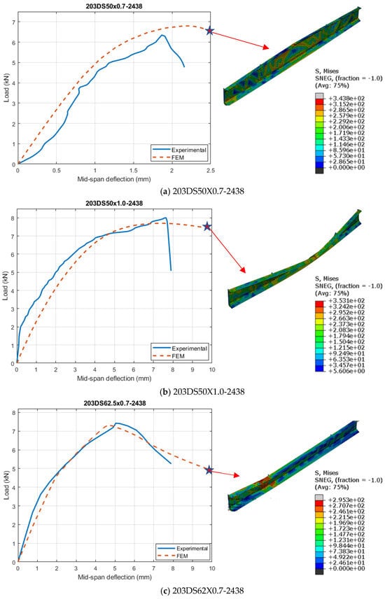
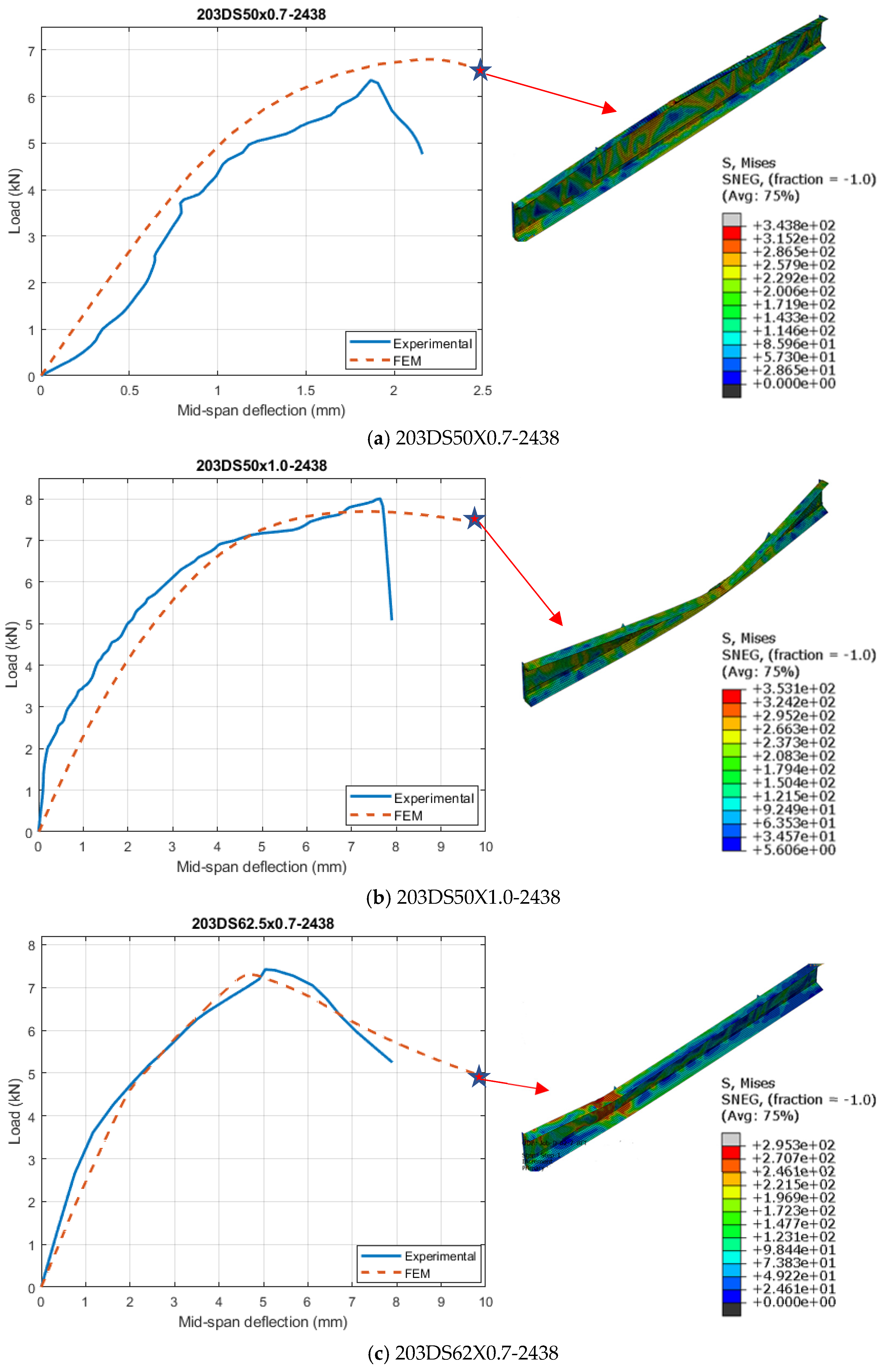
Figure 10 compares the experimental and FE load–deflection responses of the investigated Delta-Channel specimens together with the corresponding FE deformation and stress distributions at the ultimate load. The numerical models reproduce the overall nonlinear flexural response observed experimentally, including the progressive development of deformation up to the ultimate load and the subsequent post-peak response.
Figure 10.
Comparison of experimental and FEM load–deflection responses and corresponding FE stress/deformation distributions of the investigated Delta-Channel specimens.
Based on the experimental and numerical results, the Delta-Channel sections consistently exhibited higher load-carrying capacities and lower mid-span deflections than the corresponding conventional lipped channel sections. For example, the 203DS50X0.7-2438 specimen achieved an experimental ultimate load of 6.36 kN at a mid-span deflection of approximately 1.9 mm, whereas the corresponding 203CS50X0.7-2438 section reached only 2.95 kN at a deflection of approximately 11 mm. Similar behaviour was observed for the other investigated specimens, demonstrating the superior flexural resistance and deformation control provided by the Delta-Channel configuration. The FE results reproduced the measured ultimate loads with good accuracy, with Exp./FE ratios of 0.94, 1.03, and 1.02 for the 203DS50X0.7-2438, 203DS50X1.0-2438, and 203DS62X0.7-2438 specimens, respectively.
The load–deflection comparisons further show that the numerical models captured the overall nonlinear flexural response, including the progressive deformation leading to the ultimate load and the subsequent post-peak behaviour. The corresponding FE stress and deformation distributions are also consistent with the experimentally observed concentration of local deformation in the compression flange region. The improved performance of the Delta-Channel sections can be attributed to their partially closed geometry, which increases sectional rigidity and promotes a more effective distribution of stresses under bending. This enhanced sectional stability allows the Delta-Channel specimens to sustain substantially higher loads while undergoing smaller deformations than their conventional lipped-channel counterparts.
4.2. Flexural Capacity Enhancement
The influence of the proposed Delta-Channel configuration on the flexural performance of cold-formed steel beams was evaluated by comparing the experimentally measured ultimate load capacities of the Delta-Channel specimens with those of geometrically comparable conventional lipped channel sections. The comparison was undertaken to quantify the effectiveness of the modified cross-sectional geometry in improving the load-carrying capacity of cold-formed steel members subjected to four-point bending.
Table 5 shows that the Delta-Channel sections consistently achieved higher ultimate load capacities than the corresponding conventional lipped channel sections. The largest improvement was observed for specimen 203DS62X0.7-2438, which attained an ultimate load capacity of 7.43 kN compared with 3.10 kN for specimen 203CS62X0.7-2438, representing an increase of approximately 139.7%. Specimen 203DS50X0.7-2438 achieved an ultimate load capacity of 6.36 kN compared with 2.95 kN for specimen 203CS50X0.7-2438, corresponding to an increase of approximately 115.6%. Similarly, specimen 203DS50X1.0-2438 attained an ultimate load capacity of 7.95 kN, representing a 66.3% increase over the corresponding lipped channel section.
Table 5.
Flexural capacity enhancement achieved by the Delta-Channel sections.
The substantial increases in flexural capacity demonstrate the effectiveness of the proposed Delta-Channel configuration in enhancing the structural performance of cold-formed steel beams. The physical basis for the different magnitudes of capacity enhancement is related to the relative influence of plate slenderness and instability in the corresponding conventional lipped-channel sections. For the 0.7 mm sections, the thinner plate elements have higher width-to-thickness ratios and are therefore more susceptible to local and distortional instability. The Delta configuration reduces the influence of the free edges and provides additional sectional restraint through the inclined elements, resulting in substantially greater relative capacity gains of 115.6% for the 50 mm flange and 139.7% for the 62.5 mm flange. The latter represents the largest enhancement because the 62.5 mm × 0.7 mm conventional section has the highest flange width-to-thickness ratio among the compared configurations. In contrast, increasing the thickness from 0.7 to 1.0 mm for the 50 mm flange reduces the width-to-thickness ratio from 71.4 to 50.0, making the conventional lipped channel less susceptible to instability and increasing its baseline load-carrying capacity. Consequently, although the Delta configuration still provides enhanced sectional rigidity and improved resistance to instability, its relative capacity advantage decreases to 66.3%. These results indicate that the Delta configuration provides the greatest relative benefit when the corresponding conventional section is more slender and instability-sensitive.
The observed deformation patterns and corresponding FE results further indicate that the inclined elements provide additional restraint to the flange regions and reduce the extent of deformation caused by the free edges of the conventional lipped-channel sections. This geometric restraint contributes to the greater sectional stability observed for the Delta-Channel specimens and is consistent with their higher load-carrying capacities and reduced deformation at the corresponding load levels.
4.3. Structural Efficiency
The structural efficiency of the proposed Delta-Channel sections was evaluated by comparing the increase in flexural capacity with the corresponding increase in material usage relative to the conventional lipped channel sections. Since all specimens were fabricated from the same steel material, the specimen weight was used as an indicator of material consumption. The comparison provides an assessment of whether the additional material required to form the Delta configuration is justified by the resulting improvement in structural performance.
Table 6 compares the percentage increase in specimen weight with the corresponding increase in ultimate load capacity achieved by the Delta-Channel sections. The results show that the modified geometry required only a modest increase in material, ranging from approximately 28.9% to 35.0%, while producing substantially larger gains in flexural capacity. For the 50 mm flange specimens, a weight increase of approximately 28.9% resulted in load-carrying capacity improvements of 115.6% and 66.3% for the 0.7 mm and 1.0 mm sections, respectively. Similarly, the 62.5 mm flange Delta section required a 35.0% increase in weight but achieved a flexural capacity enhancement of approximately 139.7%.
Table 6.
Comparison of weight increase and flexural capacity enhancement.
The results indicate that the increase in flexural capacity significantly exceeded the corresponding increase in material usage. This demonstrates that the improved performance of the Delta-Channel sections cannot be attributed solely to the addition of material but is primarily due to the geometric modification of the cross-section. The inclined elements forming the partially closed configuration enhanced sectional rigidity and reduced the susceptibility to instability-related behaviour, enabling more efficient utilization of the available material.
Overall, the proposed Delta-Channel configuration exhibited superior structural efficiency compared with the conventional lipped channel sections. The substantial gains in load-carrying capacity achieved with relatively small increases in weight demonstrate the effectiveness of the proposed geometry as a practical approach for enhancing the flexural performance of cold-formed steel members.
4.4. Buckling and Failure Modes
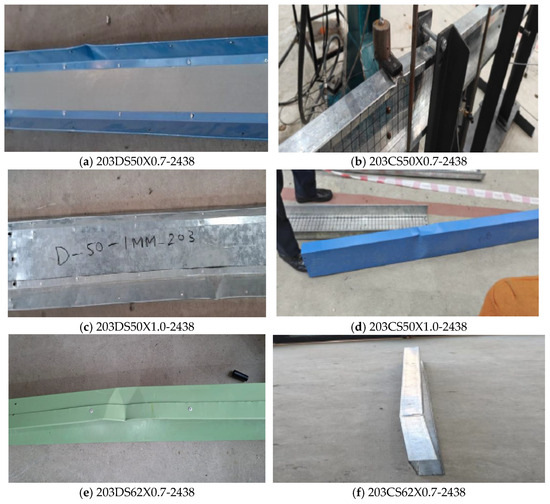
The structural behaviour of the tested specimens was evaluated under monotonic four-point bending until failure. Throughout the loading process, all specimens initially exhibited a linear elastic response followed by the gradual development of localized deformation within the compression region. As the applied load increased, local instability became evident in the flange elements, ultimately governing the failure behaviour of the investigated specimens. Figure 11 presents representative failure modes observed for the Delta-Channel specimens during testing.
Figure 11.
Typical experimental failure modes of Delta-Channel specimens subjected to four-point bending.
The development of local instability can also be interpreted from the measured load–deflection responses and the FE stress/deformation distributions presented in Section 4.1. All Delta-Channel specimens initially exhibited a predominantly linear response, followed by increasing deformation in the compression region as the applied load approached the ultimate capacity. For the 203DS50X0.7–2438 specimen, the ultimate load of 6.36 kN was reached at a mid-span deflection of approximately 1.9 mm, while the 203DS50X1.0–2438 and 203DS62.5X0.7–2438 specimens reached ultimate loads of 7.95 and 7.43 kN at approximately 7.7 and 5.1 mm, respectively. The corresponding FE predictions were 6.80 kN at 2.2 mm, 7.70 kN at 7.4 mm, and 7.30 kN at 4.7 mm. The FE stress and deformation contours show that the critical deformation develops primarily in the compression flange, with more pronounced local deformation for the wider 62.5 mm flange configuration. These observations indicate that the development of local instability is progressive rather than instantaneous, with increasing out-of-plane deformation accompanied by stiffness degradation as the ultimate load is approached. The quantitative load–deflection response therefore complements the observed failure modes by identifying the deformation level associated with the ultimate state, while the FE contours identify the corresponding critical regions within the cross-section.
The Delta-Channel sections demonstrated stable flexural behaviour throughout the loading process and were capable of sustaining significant deformation prior to ultimate failure. Failure was primarily concentrated within the compression flange region, where progressive local deformation developed as bending stresses increased. The observed deformation patterns provide further evidence of the enhanced stability of the Delta-Channel configuration, with the inclined elements providing additional restraint against local deformation and buckling of the section.
For specimen 203DS50X0.7-2438, localized deformation developed within the compression flange in the constant-moment region between the loading points. The flange experienced progressive out-of-plane deformation as the applied load increased, leading to a reduction in sectional stiffness prior to ultimate failure. Despite the occurrence of local instability, the specimen continued to sustain additional load beyond the onset of deformation, indicating a stable structural response.
Similarly, specimen 203DS62X0.7-2438 exhibited local flange buckling accompanied by deformation within the adjacent web region. The wider flange geometry increased the susceptibility of the compression element to local instability, resulting in more pronounced deformation compared with the smaller Delta section. Nevertheless, the specimen maintained its overall structural integrity and was capable of carrying substantially higher loads than the corresponding lipped channel sections.
The experimental observations also indicate that the failure behaviour of the Delta-Channel sections differed from that of the conventional lipped channel specimens. The lipped channel sections exhibited earlier initiation of local buckling and lower ultimate load capacities, whereas the Delta sections were able to sustain higher load levels before significant deformation developed. This behaviour can be attributed to the partially closed geometry of the Delta section, which increased sectional stiffness and improved the distribution of stresses within the member.
The enhanced performance of the Delta-Channel specimens is further reflected in the experimental results presented in Table 5, where substantial increases in flexural capacity were achieved compared with geometrically comparable lipped channel sections. The improved behaviour is consistent with the intended objective of the Delta configuration, namely the reduction in instability caused by the long free edges present in conventional lipped channel sections and the enhancement of overall sectional stability under bending.
Overall, the experimental observations confirmed that the proposed Delta-Channel sections exhibited favorable structural behaviour under flexural loading. The failure mechanisms were predominantly governed by local flange deformation and buckling within the compression region, while the overall section remained stable throughout the loading process. These observations provide qualitative evidence of the effectiveness of the proposed geometry and form the basis for the quantitative comparisons of load-carrying capacity, load–deflection response, and numerical model validation presented in the following sections.
4.5. Comparison with Recently Developed Built-Up and Closed Cold-Formed Steel Sections
To further assess the structural significance of the proposed Delta-Channel configuration, its performance was compared with several recently investigated built-up and closed cold-formed steel (CFS) beam systems. The comparison considers the section configuration, reported flexural-capacity improvement, material or section-component requirements, and principal failure modes, as summarized in Table 7. Since the studies considered different cross-sectional dimensions, material thicknesses, steel grades, spans, loading arrangements, and connection systems, the reported capacity improvements cannot be interpreted as a direct ranking of the investigated systems. Instead, the comparison provides a broader context for evaluating the structural efficiency and behaviour of the proposed Delta-Channel configuration.
Table 7.
Comparison of the present Delta-Channel configuration with recently investigated built-up and closed CFS systems.
The comparison indicates that the proposed Delta-Channel configuration achieves substantial flexural-capacity enhancement with a relatively modest increase in material usage. The partially closed geometry and inclined elements provide additional sectional restraint, reduce the influence of free edges, and improve resistance to local instability. In the present experimental programme, failure was predominantly associated with local deformation and buckling of the compression flange. The results therefore demonstrate the potential of the Delta-Channel concept as an efficient partially closed CFS configuration. However, because the compared studies involve substantially different geometries, material properties, connection arrangements, spans, and loading conditions, the results should be regarded as a comparative contextual assessment rather than a direct performance ranking. Further experimental and numerical investigations are required before generalized design recommendations can be established.
5. Conclusions
Within the range of section dimensions, material thicknesses, specimen lengths, and loading conditions investigated in this study, the following conclusions can be drawn:
- Within the investigated range of section dimensions and thicknesses, the Delta-Channel configuration exhibited higher flexural capacity than the corresponding conventional lipped channel sections, with experimentally observed capacity increases of approximately 115.6%, 66.3%, and 139.7% for the investigated specimen pairs.
- The Delta-Channel sections exhibited improved structural performance by achieving lower mid-span deflections and enhanced resistance to instability-related behaviour. Experimental observations showed that the partially closed configuration increased sectional rigidity and delayed the onset of local buckling compared with conventional lipped channel sections.
- For the specimens investigated in this study, the developed finite element models provided satisfactory predictions of the experimental behaviour, with a mean Exp./FE ratio of 1.07 and a coefficient of variation of 0.09 for ultimate load capacity.
- For the investigated configurations, structural efficiency assessment demonstrated that the proposed Delta-Channel geometry achieved substantially greater increases in flexural capacity than the corresponding increase in material usage. While specimen weight increased by approximately 29–35%, flexural capacity improvements ranged from approximately 66% to 140%, confirming the effectiveness of the proposed configuration as an efficient cold-formed steel beam system.
The experimental programme was limited to one specimen for each Delta-Channel configuration and therefore does not provide sufficient data to quantify specimen-to-specimen variability or experimental repeatability. Accordingly, the reported experimental results should be interpreted as a proof-of-concept demonstration of the proposed configuration rather than as a statistically representative characterization of the Delta-Channel family. The present investigation considered only monotonic four-point bending of simply supported members. Further studies should evaluate the behaviour of Delta-Channel sections under shear, combined loading, cyclic loading, and longer-span applications.
6. Future Research
Based on the observed behaviour, the Delta-Channel configuration shows potential for applications where increased sectional rigidity and resistance to instability are important, such as purlins, wall studs, and other lightweight members subjected to bending and lateral loading. The 225 mm rivet spacing adopted in the present experimental programme was found to provide satisfactory connection behaviour for the tested Delta-Channel configurations. However, because only three Delta-Channel specimens were investigated, the present results are not sufficient to establish a general design recommendation for rivet spacing or other geometric and connection parameters. Future research should therefore investigate a wider range of rivet spacings, connection arrangements, section depths, thicknesses, and flange widths to establish their influence on load transfer, stiffness, strength, and failure behaviour. Particular attention should be given to developing experimentally validated criteria for the selection of rivet spacing and connection requirements. Further studies should also evaluate the performance of Delta-Channel sections under shear, combined bending–shear and axial loading, cyclic loading, and longer-span applications. The results from an expanded experimental and numerical database can subsequently be used to develop design-oriented recommendations for the proposed Delta-Channel system.
Author Contributions
Conceptualization, Z.A.S. and M.A.K.; methodology, R.F.M.; software, R.F.M. and M.A.K.; validation, M.A.K. and A.A.; investigation, Z.A.S.; data curation, M.N.A.R.; writing—original draft preparation, A.A.; writing—review and editing, A.A. and M.N.A.R.; visualization, Z.A.S. and R.F.M.; supervision, Z.A.S. and M.A.K.; funding acquisition, Z.A.S. All authors have read and agreed to the published version of the manuscript.
Funding
This research was funded by the Higher Education Commission (HEC) of Pakistan under the National Research Program for Universities (NRPU), Grant No. NRPU-15859.
Data Availability Statement
The raw data supporting the conclusions of this article will be made available by the authors on request.
Acknowledgments
The authors would like to express their sincere gratitude to the University of Lahore for providing access to its laboratory facilities and technical resources. The authors also gratefully acknowledge the laboratory staff for their assistance and support during the experimental work.
Conflicts of Interest
Rehan Farid Mustafa is an employee of Ahad & Associates, Consulting Engineers & Planners. The paper reflects the views of the authors and not those of the company. The remaining authors declare no conflicts of interest.
Abbreviations
The following abbreviations are used in this manuscript:
| ABAQUS | ABAQUS Finite Element Analysis Software |
| AISI | American Iron and Steel Institute |
| ASTM | American Society for Testing and Materials |
| CoV | Coefficient of Variation |
| CFS | Cold-Formed Steel |
| CS | Conventional Lipped Channel Section |
| DSM | Direct Strength Method |
| DS | Delta-Channel Section |
| FE | Finite Element |
| FEA | Finite Element Analysis |
| FSM | Finite Strip Method |
| LVDT | Linear Variable Differential Transformer |
| MPa | Megapascal |
| DOW | Double Sections Forming an Overall Circular Shape Resembling an ‘O’ with ‘W’ Shaped Stiffeners |
| DM | Double M Sections |
References
- Hancock, G.J. Cold-formed steel structures. J. Constr. Steel Res. 2003, 59, 473–487. [Google Scholar] [CrossRef] [Scilit]
- Yu, W.W.; LaBoube, R.A. Cold-Formed Steel Design, 4th ed.; John Wiley & Sons: Hoboken, NJ, USA, 2010. [Google Scholar]
- American Iron and Steel Institute (AISI). North American Specification for the Design of Cold-Formed Steel Structural Members; AISI S100-16; American Iron and Steel Institute (AISI): Washington, DC, USA, 2016. [Google Scholar]
- Schafer, B.W. Cold-formed steel structures around the world: A review of recent advances in applications, analysis and design. Steel Constr. 2011, 4, 141–149. [Google Scholar] [CrossRef] [Scilit]
- Rondal, J. Cold formed steel members and structures: General Report. J. Constr. Steel Res. 2000, 55, 155–158. [Google Scholar] [CrossRef] [Scilit]
- Hancock, G.J. Cold-formed steel structures: Research review 2013–2014. Adv. Struct. Eng. 2016, 19, 393–408. [Google Scholar] [CrossRef] [Scilit]
- Hancock, G.J.; Kwon, Y.B.; Bernard, E.S. Strength design curves for thin-walled sections undergoing distortional buckling. J. Constr. Steel Res. 1994, 31, 169–186. [Google Scholar] [CrossRef] [Scilit]
- Yang, D.; Hancock, G.J. Compression tests of high strength steel channel columns with interaction between local and distortional buckling. J. Struct. Eng. 2004, 130, 1954–1963. [Google Scholar] [CrossRef] [Scilit]
- Neves, N.S.D.; Landesmann, A. Dinar Camotim, Behaviour and DSM design of CFS lipped channel beams affected by distortional-global interaction at room and elevated temperatures. Thin-Walled Struct. 2026, 225, 114325. [Google Scholar] [CrossRef] [Scilit]
- Liang, D.; Fan, S.; Dong, D.; Liu, M. Experimental investigation of global-distortional interaction buckling of stainless steel C-beams. J. Constr. Steel Res. 2024, 214, 108472. [Google Scholar] [CrossRef] [Scilit]
- Liang, D.; Fan, S.; Xu, T.; Dong, D.; Liu, M.; Wu, Y. Design of press-braked stainless steel C-beams subjected to global-distortional interaction buckling. Structures 2024, 63, 106341. [Google Scholar] [CrossRef] [Scilit]
- Martins, A.D.; Camotim, D.; Dinis, P.B. Local-distortional interaction in cold-formed steel beams: Behaviour, strength and DSM design. Thin-Walled Struct. 2017, 119, 879–901. [Google Scholar] [CrossRef] [Scilit]
- Young, B.; Hancock, G.J. Cold-formed steel channels subjected to concentrated loads. J. Struct. Eng. 2003, 129, 1003–1010. [Google Scholar] [CrossRef] [Scilit]
- Basaglia, C.; Camotim, D.; Silvestre, N. Global buckling analysis of plane and space thin-walled frames in the context of GBT. Thin-Walled Struct. 2008, 46, 79–101. [Google Scholar] [CrossRef] [Scilit]
- Schafer, B.W.; Peköz, T. Direct strength prediction of cold-formed steel members using numerical elastic buckling solutions. In Proceedings of the 14th International Specialty Conference on Cold-Formed Steel Structures, St. Louis, MI, USA, 15–16 October 1998. [Google Scholar]
- EN 1993-1-3; Eurocode 3: Design of Steel Structures—Part 1–3: General Rules—Supplementary Rules for Cold-Formed Members and Sheeting. European Committee for Standardization: Brussels, Belgium, 2006.
- Li, Q.-Y.; Young, B. Structural Performance of Cold-Formed Steel Unstiffened and Edge-Stiffened Channel Section Beams. J. Struct. Eng. 2024, 150, 04024158-1. [Google Scholar] [CrossRef] [Scilit]
- Manikandan, P.; Sukumar, S.; Kannan, K. Distortional buckling behaviour of intermediate cold-formed steel lipped channel sections with various web stiffeners under compression. Int. J. Adv. Struct. Eng. 2018, 10, 189–198. [Google Scholar] [CrossRef] [Scilit]
- Zhang, J.H.; Young, B. Numerical investigation and design of cold-formed steel built-up open section columns with longitudinal stiffeners. Thin-Walled Struct. 2015, 89, 178–191. [Google Scholar] [CrossRef] [Scilit]
- Faridmehr, I.; Osman, M.H.; Tahir, M.M.; Nejad, A.F. Behaviour and design of cold-formed steel C-sections with stiffeners. Arab. J. Sci. Eng. 2016, 41, 3169–3182. [Google Scholar] [CrossRef] [Scilit]
- Rezaeian, H.; Andarini, R.; Bock, M.; Yekrangnia, M. A Parametric Study on the Flexural Capacity of Cold-Formed Steel Stacked Built-up Sections. Int. J. Steel Struct. 2024, 24, 1142–1153. [Google Scholar] [CrossRef] [Scilit]
- Maizi, S.-E.; Hadidane, Y.; Dar, M.A. Flexural design of cold-formed steel built-up sections failing by local buckling: Development of generalised direct strength method. Eng. Struct. 2024, 308, 117967. [Google Scholar] [CrossRef] [Scilit]
- Wang, L.; Dawud, M.B.; Cai, Y. Flexural behavior and design of cold-formed steel gapped back-to-back built-up beams with discontinuous connecting plates. Thin-Walled Struct. 2024, 205, 112548. [Google Scholar] [CrossRef] [Scilit]
- Young, B.; Rasmussen, K.J.R. Tests of cold-formed channel columns. In Proceedings of the 14th International Specialty Conference on Cold-Formed Steel Structures, St. Louis, MO, USA, 15–16 October 1998; pp. 239–264. [Google Scholar]
- Manikandan, P.; Arun, N. Behaviour of Partially Closed Stiffened Cold-Formed Steel Compression Member. Arab. J. Sci. Eng. 2016, 41, 3865–3875. [Google Scholar] [CrossRef] [Scilit]
- Ma, D.; Rasmussen, K.J.R.; Zhang, H. Numerical investigation of the flexural-torsional behaviour of built-up cold-formed steel beams. Thin-Walled Struct. 2025, 212, 113183. [Google Scholar] [CrossRef] [Scilit]
- Durmaz, M.; Daloğlu, A. Nonlinear finite element analysis of cold-formed steel plain angle columns. Chall. J. Struct. Mech. 2016, 2, 220–225. [Google Scholar] [CrossRef] [Scilit]
- Schafer, B.W. Designing cold-formed steel using the Direct Strength Method. In Proceedings of the 18th International Specialty Conference on Cold-Formed Steel Structures, Orlando, FL, USA, 26–27 October 2006. [Google Scholar]
- Moen, C.D.; Schafer, B.W. Direct Strength Method for design of cold-formed steel columns with holes. J. Struct. Eng. 2011, 137, 559–570. [Google Scholar] [CrossRef] [Scilit]
- Schafer, B.W. Advances in Direct Strength Design of Thin-Walled Members. In Proceedings of the ASSCCA 2003, Sydney, Australia, 22–25 June 2003. [Google Scholar]
- Khan, M.A.; Mustafa, R.F.; Siddiqi, Z.A.; Masood, R. Validation of AISI Design of Cold-Formed Steel Beams Using Non-Linear Finite Element Analysis. Appl. Sci. 2024, 14, 8492. [Google Scholar] [CrossRef] [Scilit]
- Khan, M.A. In-Plane and Out-Of-Plane Behavior of Slender Cold Formed Sections. Doctoral Dissertation, The University of Lahore, Lahore, Pakistan, 2024. [Google Scholar]
- Schafer, B.W. Review: The Direct Strength Method of cold-formed steel member design. J. Constr. Steel Res. 2008, 64, 766–778. [Google Scholar] [CrossRef] [Scilit]
- Dassault Systèmes Simulia Corp. ABAQUS Analysis User’s Manual; Version 2021; Dassault Systèmes Simulia Corp.: Providence, RI, USA, 2021. [Google Scholar]
- ASTM A370-24; Standard Test Methods and Definitions for Mechanical Testing of Steel Products. ASTM International: West Conshohocken, PA, USA, 2024. [CrossRef] [Scilit]
- Ajwad, A.; Di Benedetto, S.; Latour, M.; Rizzano, G. A component method approach for single-sided beam-to-column joints with CHS column and welded double-tee beam. Thin-Walled Struct. 2024, 202, 112055. [Google Scholar] [CrossRef] [Scilit]
- Sato, A.; Elettore, G.; Ajwad, A.; Di Benedetto, S.; Latour, M.; Francavilla, A.B.; Rizzano, G. Stiffness of Welded T-joints Between SHS Profiles and Through Plates. In Proceedings of the STESSA 2024, Salerno, Italy, 8–10 July 2024; Lecture Notes in Civil Engineering; Springer: Cham, Switzerland, 2024; Volume 519, pp. 350–361. [Google Scholar] [CrossRef] [Scilit]
- Latour, M.; Ajwad, A.; Di Benedetto, S.; Rizzano, G. Component-based model for flexural behaviour of single-sided SHS column and through-beam joints. J. Constr. Steel Res. 2026, 244, 110479. [Google Scholar] [CrossRef] [Scilit]
- Ajwad, A.; Di Benedetto, S.; Latour, M.; Rizzano, G. Stiffness characterisation of lattice joints with CHS chords and longitudinal branch plates. Eng. Struct. 2026, 359, 122755. [Google Scholar] [CrossRef] [Scilit]
- Ajwad, A. Modellazione Per Componenti Di Nodi Costituiti Da Sezioni Cave Saldate Ad Elementi Esterni E Passanti. Ph.D. Thesis, The University of Salerno, Fisciano, Italy, 2026. [Google Scholar]
- Ajwad, A.; Di Benedetto, S.; Latour, M.; Rizzano, G. Stiffness of welded T-joints with CHS chord members and passing-through longitudinal plates. Structures 2025, 71, 107963. [Google Scholar] [CrossRef] [Scilit]

Disclaimer/Publisher’s Note: The statements, opinions and data contained in all publications are solely those of the individual author(s) and contributor(s) and not of MDPI and/or the editor(s). MDPI and/or the editor(s) disclaim responsibility for any injury to people or property resulting from any ideas, methods, instructions or products referred to in the content. |
© 2026 by the authors. Licensee MDPI, Basel, Switzerland. This article is an open access article distributed under the terms and conditions of the Creative Commons Attribution (CC BY) license.