


Abstract
Grouted connection segments are key load-transfer components in offshore wind jacket structures, and their axial compressive performance is essential for the safety and reliability of the foundation system. This paper develops a finite element model of a grouted connection segment incorporating steel-fiber-reinforced high-strength grout to investigate its mechanical behavior and parametric effects under axial compression. A 1:7-scale model test is conducted to verify the numerical model through comparisons of the load–displacement response and strain responses at key locations. The steel tubes are simulated using a trilinear hardening elastoplastic model, while the steel-fiber-reinforced high-strength grout is represented using the concrete damaged plasticity model with corresponding tensile and compressive constitutive relationships and damage parameters to characterize its nonlinear response. Based on the validated model, a full-scale numerical model is established to analyze the effects of steel tube thickness, shear key spacing, shear key height, and shear key width using the control variable method. The results indicate that steel tube thickness has the most significant influence on the ultimate bearing capacity and can improve the load-bearing capacity and ductility of the structure. Shear key spacing mainly affects axial stiffness and deformation compatibility, while shear key height and width have limited effects on the ultimate bearing capacity but contribute to local deformation control and stiffness enhancement. The findings provide a validated numerical basis for evaluating the axial compressive behavior of steel-fiber-reinforced grouted connections and offer a useful reference for the design and parameter optimization of grouted connection segments in deep-water offshore wind jacket structures.
1. Introduction
Offshore wind power has developed rapidly in recent years and has become an important approach for promoting renewable energy utilization and reducing carbon emissions. With the continuous expansion of offshore wind farms from nearshore areas to deep-water regions, higher requirements have been placed on the safety and reliability of offshore wind turbine support structures [1,2]. Jacket foundations have been widely used in deep-water offshore wind structures because of their high structural stiffness, good overall stability, and strong adaptability to complex marine environments [3,4]. During long-term service, jacket structures are subjected to wind, wave, current, and cyclic loads, which may lead to fatigue damage and threaten structural safety [5,6]. As a key load-transfer component between the steel pile and the upper jacket structure, the grouted connection segment directly affects the mechanical performance and service reliability of the foundation system [7]. Therefore, it is important to investigate the axial compressive behavior and parameter influence mechanism of grouted connection segments in deep-water offshore wind jacket structures.
Extensive experimental and theoretical studies have been conducted on the mechanical behavior of grouted connections. Smith et al. [8] found that the failure mode of grouted connections with a low diameter-to-thickness ratio was mainly characterized by the combined action of inclined cracking and interfacial shear slip. Aritenang et al. [9] indicated that steel tube yielding was one of the dominant failure mechanisms and proposed a bearing capacity calculation method considering interfacial friction. Chen et al. [10,11] investigated the behavior of grouted connections under different axial load conditions and pointed out that a high axial load may affect the bearing behavior, while local buckling of the steel tube is a typical failure mode. Thomas et al. [12] and Schaumann et al. [13] studied the responses of grouted connections under bending and combined bending–axial loading, respectively, and reported that local stress concentration and stiffness degradation may occur in critical regions. Lamport et al. [14] and Lotsberg [15] further analyzed the effects of grout strength, interfacial slip, and local stress distribution on the load-transfer mechanism and structural design of grouted connections.
The effects of shear key parameters and interfacial load transfer have also attracted considerable attention. Song et al. [16] and Lee et al. [17] showed that the size and spacing of shear keys significantly influence the interfacial stress distribution, load-transfer path, and slip response of grouted connections. Andersen et al. [18] provided design recommendations for grouted connections in offshore monopile foundations. Wu et al. [19] proposed a calculation method for the axial bearing capacity of steel pipe-to-sleeve grouted connections, while Zhong et al. [20] analyzed the load-transfer characteristics of grouted connection segments in a three-pile offshore wind foundation. With the development of numerical methods, finite element analysis has been increasingly used to study the nonlinear responses of grouted connections under complex loading conditions. Chellappan et al. [21] and Tziavos et al. [22,23] investigated the effects of grout strength, friction length, and shear key arrangement on the bearing capacity and stiffness of grouted connections. Chen et al. [24,25,26] carried out numerical studies on grouted connections under combined loads, axial loads, and compression–bending actions and demonstrated that axial force, bending moment, shear key configuration, length-to-diameter ratio, and radial stiffness can affect the interfacial stress distribution, local deformation, and bearing performance. Huang et al. [27] and Wang et al. [28] further verified the applicability of finite element methods in fatigue evaluation and shear bearing capacity analysis.
Recently, material modification and structural optimization have been considered as effective approaches to improve the performance of grouted connections. Yu et al. [29] reported that ultra-high-performance fiber-reinforced concrete exhibits excellent strength, toughness, and durability, which makes it suitable for complex loading environments. Sui et al. [30] proposed a grouted connection using ultra-high-performance fiber-reinforced concrete and verified its favorable compressive and tensile performance through experimental and numerical analyses. Kang et al. [31] indicated that the bridging effect of steel fibers can effectively improve the crack resistance and ductility of ultra-high-performance fiber-reinforced concrete, thereby enhancing deformation compatibility during loading. However, existing studies have mainly focused on conventional grouting materials and traditional shear key parameters. The effects of structural parameters on the axial compressive behavior of grouted connection segments using steel-fiber-reinforced high-strength grouting materials are still not sufficiently understood. In particular, the relative influences of steel tube thickness, shear key spacing, shear key height, and shear key width on bearing capacity, axial stiffness, and deformation compatibility require further investigation.
Although previous studies have confirmed that shear key configuration affects the load transfer and bearing behavior of grouted connections [16,17,21,22,23,24,25,26], the reported relative influence of individual structural parameters is not fully consistent. Some studies have indicated a pronounced influence of shear key dimensions on bearing performance, whereas the relative importance of steel tube confinement and shear key parameters may vary among different connection configurations. These differences may be associated with variations in grout type, connection geometry and structural scale, loading conditions, investigated parameter ranges, and interface modeling assumptions. Therefore, further investigation is required to clarify the effects of key structural parameters on steel-fiber-reinforced grouted connections under axial compression.
To address the above research gap, this study develops a three-dimensional finite element model in ABAQUS 2023 to investigate the axial compressive behavior of jacket grouted connection segments incorporating steel-fiber-reinforced high-strength grout. The nonlinear response of the fiber-reinforced grout is represented using appropriate tensile and compressive constitutive relationships and corresponding damage parameters. A 1:7-scale axial compression test is conducted to validate the numerical model through comparisons of the load–displacement response and strain responses at key locations. Based on the validated modeling framework, a full-scale numerical model is established, and the effects of steel tube thickness, shear key spacing, shear key height, and shear key width on the bearing capacity, deformation characteristics, and failure response are investigated using the control variable method. The corresponding influence mechanisms are further discussed in terms of steel tube confinement and interfacial shear transfer. The principal contribution of this study is the establishment of a validated numerical model for steel-fiber-reinforced grouted connections and the clarification of their parameter-dependent axial compressive behavior, providing a useful reference for the structural design and parameter optimization of grouted connection segments in deep-water offshore wind jacket structures. It should be noted that fatigue under cyclic loading and corrosion-induced defects caused by harsh marine environments are beyond the scope of the present study and are therefore not considered.
2. Scaled Experimental and Finite Element Model
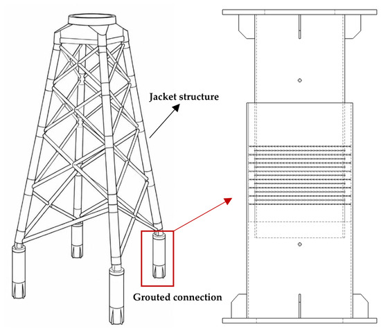
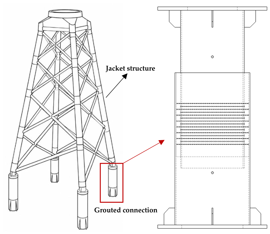
Offshore wind power has gradually expanded from shallow-water regions to deeper offshore areas in recent years. Among various foundation types, jacket foundations are widely used in deep-water offshore wind turbines because of their favorable structural stiffness, load-carrying capacity, and adaptability to complex marine environments. The grouted connection segment, located between the jacket leg and the foundation pile, is a critical load-transfer component that ensures the effective transmission of axial and lateral loads from the superstructure to the foundation system. Since the mechanical performance of the grouted connection directly affects the safety and serviceability of the entire foundation, it has become one of the key concerns in the design of offshore wind jacket structures. Figure 1 illustrates the jacket structure and the grouted connection segment investigated in this study.
Figure 1.
Schematic illustration of the jacket structure and the grouted connection segment investigated in this study.
2.1. Scaled Experimental Model
A scaled model test was conducted to provide experimental data for the validation of the finite element model developed in ABAQUS 2023. The grouted connection segment adopted a coaxial sleeve configuration consisting of an outer steel tube, a grouting layer, and an inner steel tube. Annular shear keys were arranged between the inner and outer steel tubes to enhance the interfacial shear transfer capacity. Both the inner and outer steel tubes were made of Q355 steel, and the shear keys were fabricated using smooth round bars with a diameter of 6 mm welded to the steel tube surfaces. The grouting material was SikaGrout-3560 CN, a high-strength cementitious grout reinforced with copper-plated micro steel fibers at a volume fraction of 1.5%, aiming to improve the crack resistance and deformation compatibility of the grouting layer.
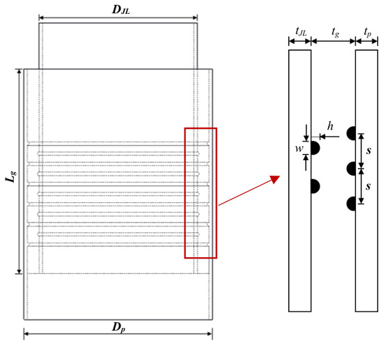
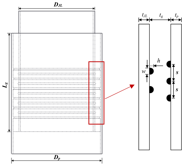
The prototype specimen was designed based on a grouted connection segment of an offshore wind jacket foundation, and the scaled specimen was fabricated with a geometric scale ratio of 1:7. The dimensions of the scaled model were determined according to the actual engineering parameters and the recommended range of the shear key height-to-spacing ratio in the DNV code [32], so as to ensure reasonable similarity between the scaled model and the prototype structure in terms of geometric characteristics and mechanical response. The geometric configuration and parameter definitions of the grouted connection segment are illustrated in Figure 2, and the main geometric dimensions of the specimen are listed in Table 1.
Figure 2.
Geometric configuration and parameter definitions of the grouted connection segment.
Table 1.
Dimensions of the test specimen (unit: mm).
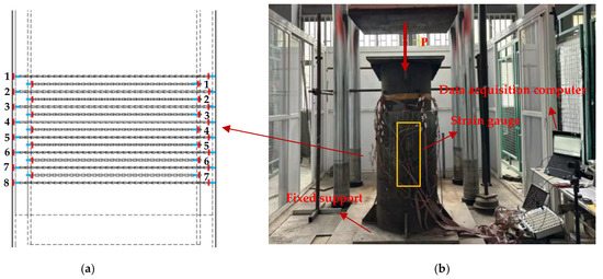
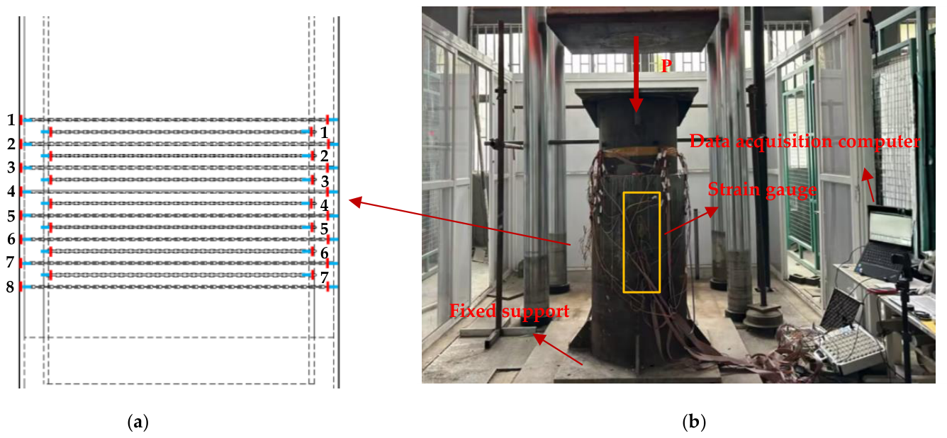
The axial compression test was performed using an electro-hydraulic servo testing machine. During the loading process, the axial load, displacement, and strain responses of the steel tubes were recorded. The loading arrangement and strain measuring point layout are shown in Figure 3. The strain gauges were numbered in the form of “W/N-measuring point number”, where W and N represent the measuring points on the outer and inner steel tubes, respectively.
Figure 3.
Loading setup and measuring point layout of the specimen. (a) Arrangement of strain gauges on the specimen. (b) Axial compression test setup and data acquisition system. Numbers 1–8 and 1–7 indicate the strain-gauge measuring point numbers on the outer and inner steel tubes, respectively.
2.2. Finite Element Model
2.2.1. Material Constitutive Models
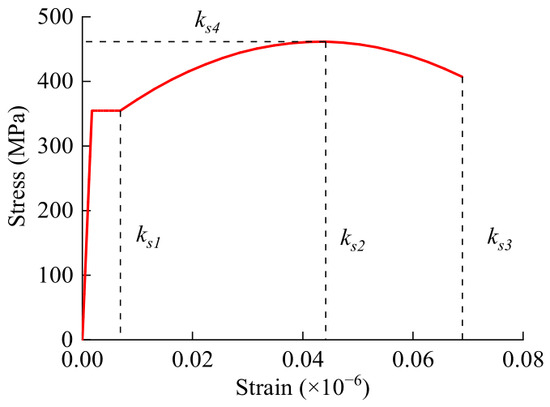
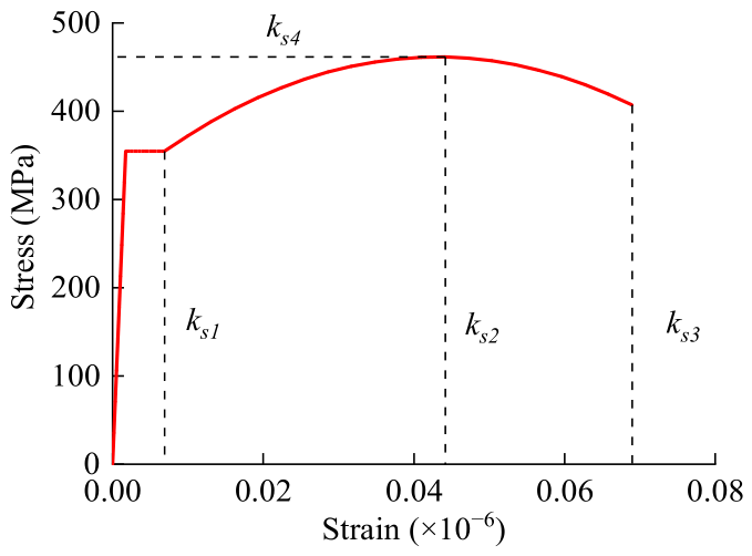
To accurately simulate the nonlinear mechanical behavior of the grouted connection segment under axial compression, constitutive models were established for both steel and grouting material. The steel tubes were simulated using an elastoplastic constitutive model based on the von Mises yield criterion, and the strain-hardening behavior after yielding was considered. To describe the continuous stress–strain response of steel from the elastic stage to the yielding and hardening stages, a trilinear hardening model was adopted, as shown in Figure 4.
Figure 4.
Trilinear hardening model for steel.
The grouting layer was described using the Concrete Damaged Plasticity (CDP) model in ABAQUS 2023, which can represent the nonlinear deformation and damage evolution of cementitious materials under compression and tension. To obtain reasonable material parameters for the finite element analysis, tensile tests of steel and uniaxial compression and tension tests of the grouting material were conducted. Based on the material test results and the corresponding constitutive calculation method, the compressive and tensile stress–strain relationships of the grouting material were established. The plastic strain and damage parameters required for the CDP model were then extracted from these stress–strain relationships. The plasticity parameters defining the yield surface, non-associated flow rule, and numerical regularization of the CDP model are summarized in Table 2. A dilation angle of 32°, a flow potential eccentricity of 0.1, a biaxial-to-uniaxial compressive strength ratio of 1.16, a shape factor Kc of 2/3, and a viscosity parameter of 0.005 were adopted. The steel fibers were not explicitly modeled as discrete entities in the finite element model. Instead, their macroscopic effects were incorporated through the experimentally established tensile and compressive constitutive relationships and the corresponding damage parameters of the steel-fiber-reinforced grout.
Table 2.
Plasticity parameters adopted in the CDP model.
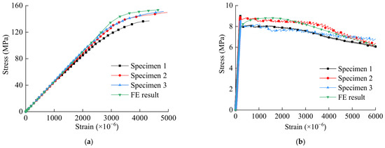
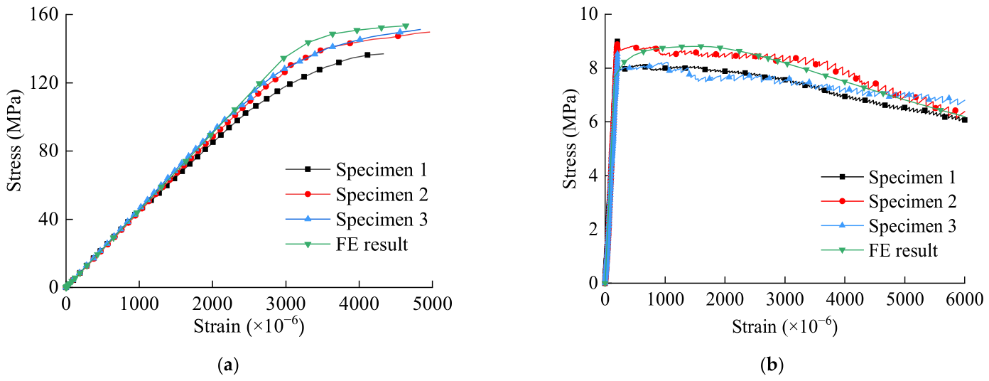
To verify the rationality of the constitutive model of the grouting material, the calculated stress–strain curves were compared with the experimental results, as shown in Figure 5. The comparison indicates that the numerical curves can reasonably capture the peak strength, elastic response, and post-peak softening behavior of the grouting material under both compression and tension. Therefore, the adopted material constitutive models can be used for the subsequent finite element analysis of the grouted connection segment.
Figure 5.
Verification of constitutive relationships of the grouting material: (a) axial compressive stress–strain curves; (b) tensile stress–strain curves.
2.2.2. Element Type and Mesh Generation
A three-dimensional finite element model of the grouted connection segment was established using ABAQUS 2023. The steel tubes and grouting layer were mainly discretized using eight-node linear reduced-integration solid elements (C3D8R), which can provide a reasonable balance between computational accuracy and convergence efficiency. Six-node wedge elements (C3D6) were used in local transition regions to improve mesh compatibility.
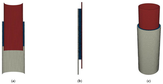
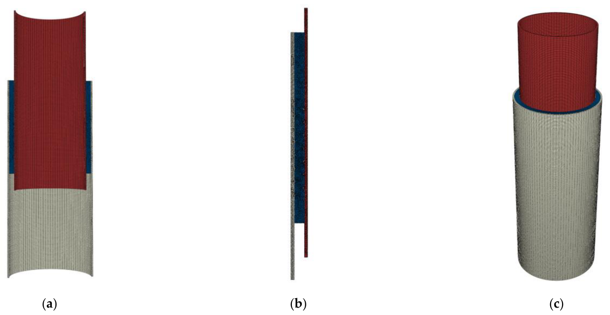
The whole model was meshed using a structured mesh scheme. Considering the differences in material properties and mechanical responses between the steel tubes and the grout, different mesh discretization strategies were adopted for these components. At least three elements were assigned through the thickness of the steel tubes to better capture the radial stress variation and local deformation. A relatively denser mesh was adopted in the grout layer to improve the representation of strain concentration, interface slip, and material damage. Local mesh refinement was applied at the shear key roots, steel tube ends, and interfacial transition regions to improve the simulation accuracy of local stress concentration and nonlinear deformation. Smooth mesh transitions were maintained between the refined and regular regions to ensure acceptable element quality while controlling the computational cost. The finite element mesh of the grouted connection segment is shown in Figure 6.
Figure 6.
Finite element mesh of the grouted connection segment: (a) cross section; (b) shear key region; (c) full model.
2.2.3. Contact Interactions and Boundary Conditions
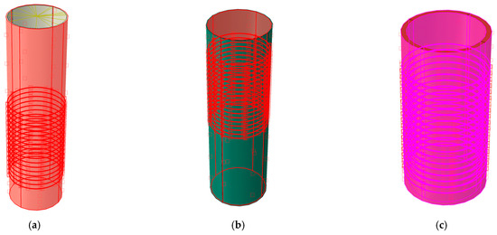
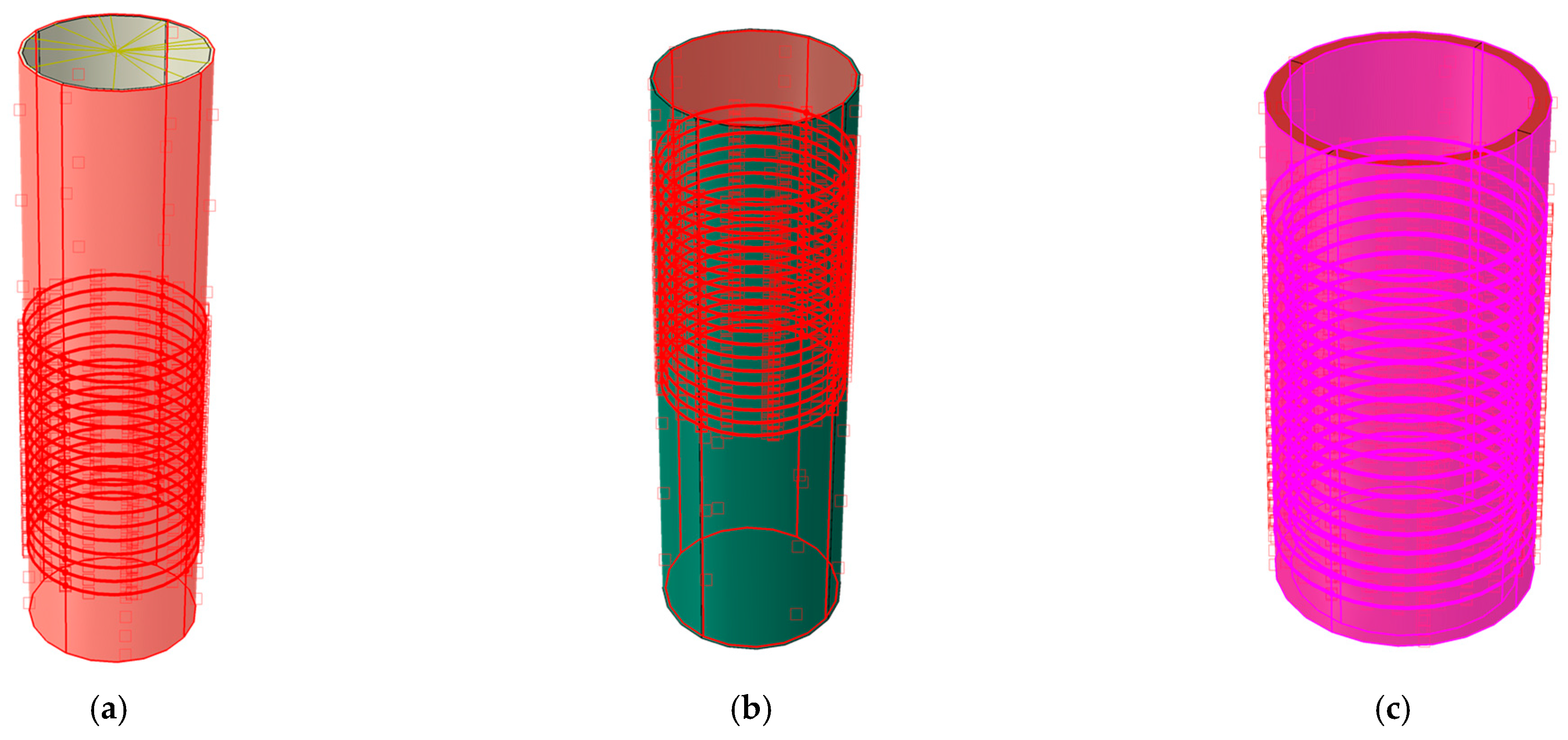
Surface-to-surface contact was adopted to simulate the interfacial interaction among the inner steel tube, grouting layer, and outer steel tube. The steel tube surfaces were defined as master surfaces, while the grouting material surfaces were defined as slave surfaces. Hard contact was adopted in the normal direction. In the tangential direction, a penalty-based Coulomb friction formulation was used to simulate the frictional resistance and relative sliding at the steel tube–grout interfaces. The friction coefficient was set to 0.4 with reference to DNV-OS-J101 [33]. The contact settings of the finite element model are shown in Figure 7.
Figure 7.
Contact interaction settings in the finite element model: (a) inner steel tube as the master surface; (b) outer steel tube as the master surface; (c) grouting material as the slave surface.
For the boundary conditions, all translational degrees of freedom at the bottom of the model were constrained. An axial displacement load was applied at the top through a reference point, and rigid coupling was used to transfer the load uniformly to the top surface of the specimen. This loading and boundary condition arrangement was used to reproduce the axial compression condition of the grouted connection segment. Accordingly, the numerical model considers the grouted connection under concentric monotonic axial compression. Eccentric compression, combined axial compression and bending, repeated loading, corrosion-induced defects, and material fatigue are not included in the present analysis.
2.2.4. Finite Element Model Validation
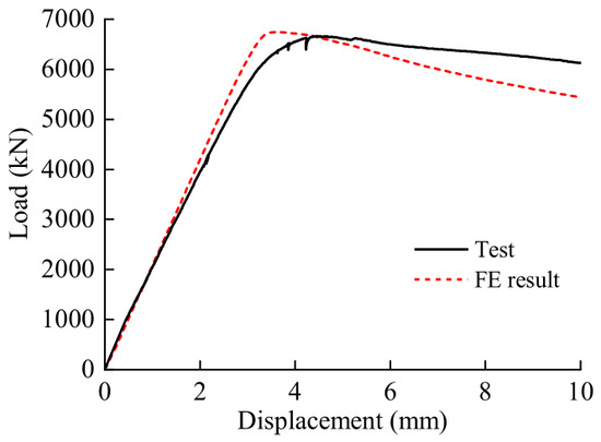
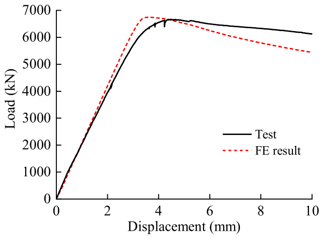
The reliability of the finite element model was verified by comparing the numerical results with the experimental results. The load–displacement curves obtained from the test and numerical simulation are shown in Figure 8. The numerical and experimental curves exhibit similar overall trends, both of which include the initial linear stage, nonlinear development stage, and post-peak descending stage. The ultimate bearing capacities obtained from the test and simulation were 6665 kN and 6742 kN, respectively, with a relative error of 1.16%, indicating good agreement between the two results. This demonstrates that the established finite element model can reasonably reflect the global mechanical response and deformation characteristics of the grouted connection segment under axial compression.
Figure 8.
Verification results of the finite element model based on load–displacement curves.
From the load–displacement response, the numerical simulation can also capture the nonlinear development near the peak load, especially in the yielding stage and post-peak stage. This indicates that the adopted material constitutive models, contact interactions, and boundary conditions are reasonable for the simulation of the axial compressive behavior of the grouted connection segment.
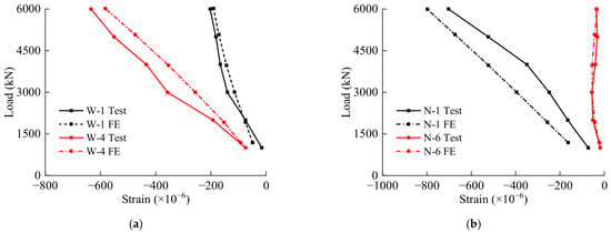
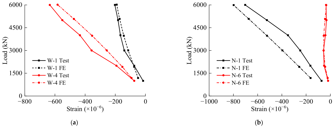
To further verify the capability of the finite element model in predicting local mechanical responses, the strain responses at key measuring points of the inner and outer steel tubes were compared, as shown in Figure 9. The numerical and experimental strain responses show similar variation trends during loading. The strains at the key locations gradually increase with the applied load, and no abrupt variation is observed during the loading process. Meanwhile, the numerical results can reasonably capture the nonlinear strain development near the peak load. These comparisons indicate that the established finite element model has good applicability in simulating both local stress transfer and deformation response, and it can be used for the subsequent parametric analysis.
Figure 9.
Comparison of strain responses at key measuring points of the inner and outer steel tubes: (a) outer steel tube; (b) inner steel tube.
3. Full-Scale Numerical Model and Parametric Scheme
3.1. Full-Scale Numerical Model
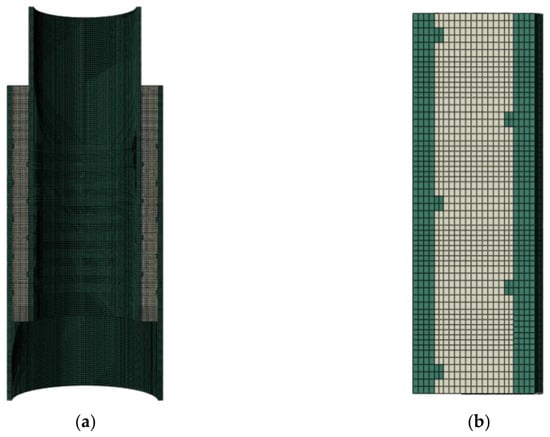
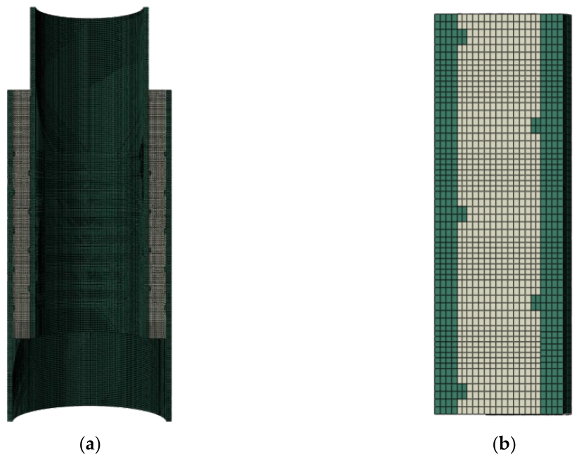
Based on the validated finite element model, a full-scale numerical model of the grouted connection segment in a deep-water offshore wind jacket structure was established for parametric analysis. The model adopted the same coaxial sleeve configuration consisting of the outer steel tube, grouting layer, and inner steel tube, and the connection segment was assumed to be constructed using the pre-grouting method. The geometric dimensions were determined according to practical engineering parameters, and the model cross-section and local mesh are shown in Figure 10.
Figure 10.
Full-scale numerical model of the grouted connection segment: (a) model cross section; (b) local mesh.
3.2. Parametric Scheme
To investigate the effects of structural parameters on the axial compressive performance of the grouted connection segment, a series of parametric models were designed based on the baseline model using the control variable method. The investigated parameters included steel tube thickness, shear key spacing, shear key height, and shear key width. The geometric parameters of the baseline model and the value ranges of the variables are listed in Table 3.
Table 3.
Geometric parameters and value ranges of numerical models for the grouted connection segment (unit: mm).
Based on the parameter ranges listed in Table 3, three groups of parametric analyses were conducted, including the effect of steel tube thickness and shear key spacing, the effect of steel tube thickness and shear key width, and the effect of shear key spacing and shear key height. During each analysis, the remaining geometric parameters were kept unchanged to clarify the influence of the selected variables. The ultimate bearing capacity, ultimate displacement, load–displacement response, and stiffness characteristics were selected as the main indicators for evaluating the axial compressive performance of the grouted connection segment.
It should be noted that the control variable method adopted in this study was intended to compare the relative effects of the selected geometric parameters within the investigated parameter combinations. A comprehensive statistical quantification of the interaction effects among all parameters and the global optimization of parameter combinations were not performed. Therefore, the conclusions are limited to the investigated parameter ranges and the adopted loading and modeling assumptions.
4. Parametric Results and Discussion of the Full-Scale Model
4.1. Effect of Steel Tube Thickness and Shear Key Spacing
To investigate the effect of steel tube thickness and shear key spacing on the axial compressive performance of the grouted connection segment, comparative analyses were conducted by varying the steel tube thickness under different shear key spacings while keeping the other parameters unchanged.
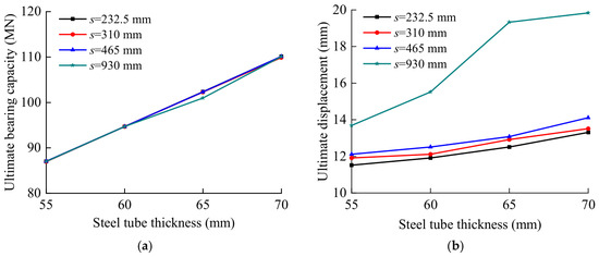
The ultimate bearing capacity increases with the steel tube thickness for all shear key spacings, as shown in Figure 11a. When the shear key spacing is 930 mm, the ultimate bearing capacity increases from 86.9 MN to 110.1 MN as the steel tube thickness increases from 55 mm to 70 mm, corresponding to an increase of 26.7%. When the shear key spacing is 232.5 mm, the ultimate bearing capacity increases from 87.0 MN to 110.1 MN, with an increase of 26.6%. These results indicate that steel tube thickness has a significant influence on the axial bearing capacity of the grouted connection segment.
Figure 11.
Effect of steel tube thickness on ultimate responses under different shear key spacings: (a) ultimate bearing capacity; (b) ultimate displacement.
Compared with the ultimate bearing capacity, the ultimate displacement is more sensitive to shear key spacing, as shown in Figure 11b. When the shear key spacing is 232.5 mm, the ultimate displacement increases from 11.5 mm to 13.3 mm, with an increase of 15.7%. In contrast, when the shear key spacing is 930 mm, the ultimate displacement increases from 13.7 mm to 19.8 mm, with an increase of 44.5%. This indicates that, when the shear keys are sparsely arranged, increasing the steel tube thickness can provide stronger radial confinement, delay the development of local deformation, and improve the deformation compatibility and ductility of the structure.
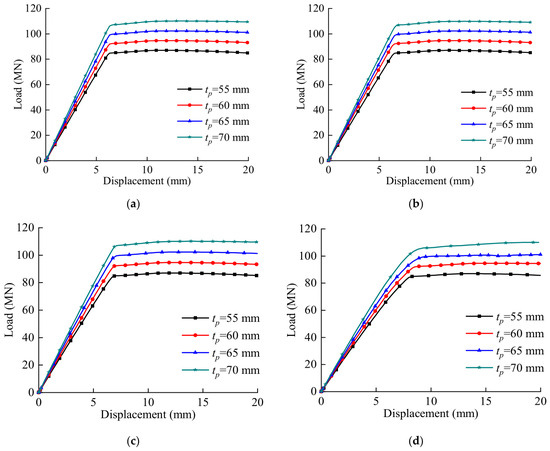
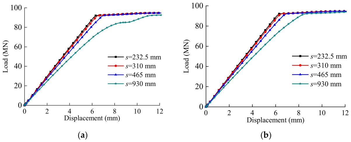
The load–displacement curves under different shear key spacings are shown in Figure 12. With increasing steel tube thickness, the curves generally move upward, the peak load increases, and the post-peak descending branch becomes more gradual. This behavior indicates that both structural stiffness and sustained load-bearing capacity are improved. The improvement can be attributed to the enhanced circumferential restraint provided by the thicker steel tube, which can effectively restrain local buckling of the steel tube and radial deformation of the grouting layer. As a result, the cooperative behavior between the steel tube and the grouting layer is improved, thereby enhancing the axial compressive performance of the grouted connection segment.
Figure 12.
Comparison of load–displacement curves under different shear key spacings: (a) s = 232.5 mm; (b) s = 310 mm; (c) s = 465 mm; (d) s = 930 mm.
4.2. Effect of Steel Tube Thickness and Shear Key Width
To investigate the effects of steel tube thickness and shear key width on the axial compressive performance of the grouted connection segment, comparative analyses were carried out by varying the steel tube thickness under different shear key widths while keeping the remaining parameters unchanged.
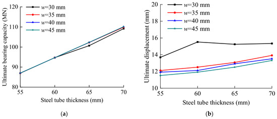
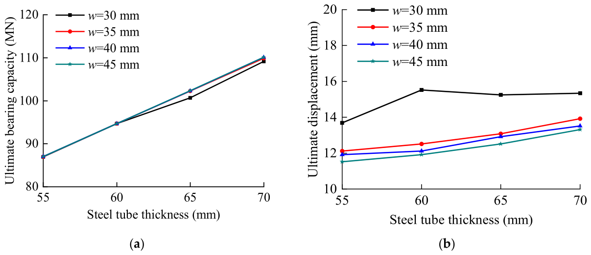
As shown in Figure 13a, the ultimate bearing capacity increases with increasing steel tube thickness under all shear key width conditions. When the steel tube thickness increases from 55 mm to 70 mm, the ultimate bearing capacity increases significantly, whereas the influence of shear key width on the ultimate bearing capacity remains relatively limited. For a given steel tube thickness, the differences in ultimate bearing capacity among different shear key widths are small, indicating that steel tube thickness is the dominant factor governing the bearing capacity of the grouted connection segment.
Figure 13.
Effect of steel tube thickness on ultimate responses under different shear key widths: (a) ultimate bearing capacity; (b) ultimate displacement.
Compared with the ultimate bearing capacity, the ultimate displacement is more sensitive to the shear key width, as shown in Figure 13b. For the case with a shear key width of 30 mm, the ultimate displacement increases from 13.68 mm to 15.52 mm as the steel tube thickness increases from 55 mm to 60 mm, reaching the maximum value. With a further increase in steel tube thickness, the ultimate displacement decreases slightly and then remains relatively stable. For the cases with shear key widths of 35–45 mm, the ultimate displacement generally increases with increasing steel tube thickness. Moreover, compared with the case of w = 30 mm, the ultimate displacement is noticeably lower when the shear key width increases to 35–45 mm, indicating that increasing the shear key width can effectively restrain axial compression deformation and improve the deformation compatibility of the grouted connection segment.
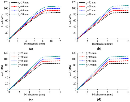
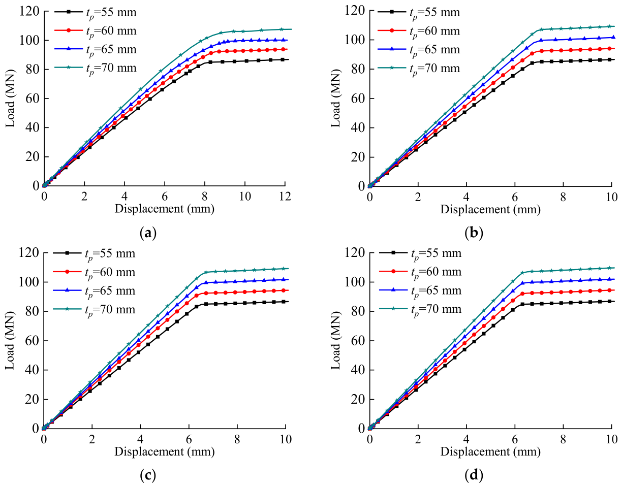
The load–displacement curves corresponding to different shear key widths are presented in Figure 14. For all cases, increasing the steel tube thickness results in higher load levels throughout the loading process and significantly increases the peak load. The curves exhibit similar shapes, including an initial linear stage, a nonlinear development stage, and a post-peak softening stage. This indicates that steel tube thickness plays a decisive role in enhancing the load-bearing performance of the grouted connection segment.
Figure 14.
Comparison of load–displacement curves under different shear key widths: (a) w = 30 mm; (b) w = 35 mm; (c) w = 40 mm; (d) w = 45 mm.
For a given shear key width, the load–displacement curves gradually shift upward as the steel tube thickness increases, indicating a continuous improvement in the axial load-carrying capacity. In contrast, the influence of shear key width on the peak load is relatively limited. Increasing the shear key width mainly affects the deformation response by enlarging the local contact and load-transfer area between the shear keys and the grout layer, thereby improving interfacial load transfer and reducing local deformation. Overall, steel tube thickness primarily governs the ultimate bearing capacity, whereas shear key width mainly influences the deformation response and deformation compatibility of the grouted connection segment.
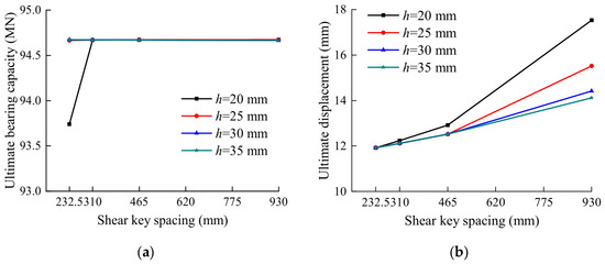
4.3. Effect of Shear Key Spacing and Shear Key Height
To investigate the effect of shear key spacing and shear key height on the bearing response of the grouted connection segment, comparative analyses were conducted by varying the shear key spacing under different shear key heights while keeping the steel tube thickness and shear key width unchanged.
The ultimate bearing capacity under different combinations of shear key height and spacing is shown in Figure 15a. The overall variation is relatively small, and most values remain around 94.6 MN. Only the case with a shear key height of 20 mm and a spacing of 232.5 mm shows a slightly lower value of approximately 93.7 MN. No clear monotonic relationship is observed with the variation in shear key spacing or height, indicating that this parameter combination has a limited influence on the ultimate bearing capacity.
Figure 15.
Effect of shear key spacing on ultimate responses under different shear key heights: (a) ultimate bearing capacity; (b) ultimate displacement.
Compared with the ultimate bearing capacity, the ultimate displacement exhibits more pronounced variations with shear key spacing and height, as shown in Figure 15b. For all investigated shear key heights, the ultimate displacement generally increases with increasing spacing. The increase is relatively limited from 232.5 mm to 465 mm but becomes pronounced when the spacing reaches 930 mm, particularly for smaller shear key heights. Under small spacing conditions, the differences among the investigated shear key heights are minor. As the spacing increases, the influence of shear key height becomes more evident, and increasing the shear key height effectively reduces the ultimate displacement. These results indicate that the deformation response is more sensitive to shear key height under sparse shear key arrangements.
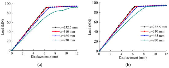
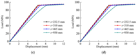
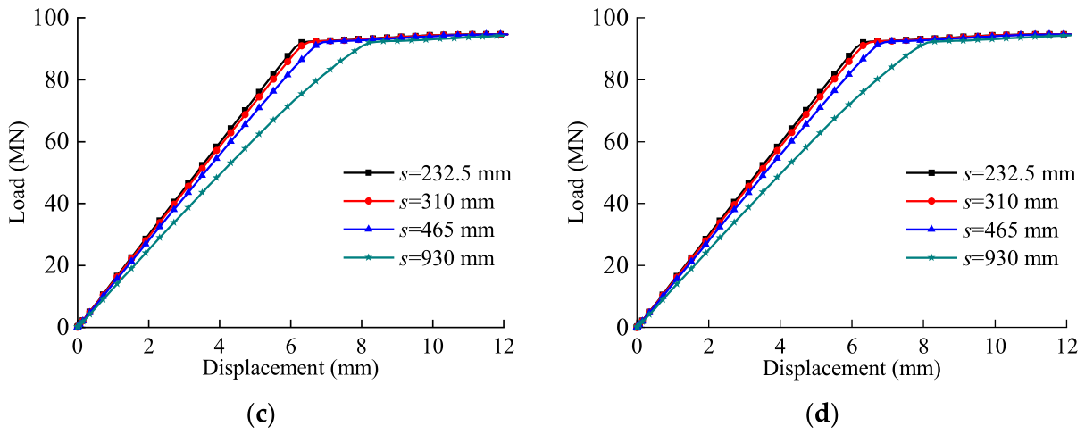
The load–displacement curves under different shear key heights are shown in Figure 16. The peak loads of different cases are close to each other. However, with increasing shear key spacing, the displacement required to reach the peak load increases, and the pre-peak deformation process becomes longer. This indicates that larger shear key spacing weakens the axial restraint effect of the connection segment and results in greater axial compression deformation before reaching the ultimate state. This behavior is mainly caused by the reduction in the number of shear keys participating in load transfer per unit length, which weakens the continuity of interfacial shear transfer. Increasing the shear key height can enhance the local shear resistance and thereby improve the deformation compatibility of the grouted connection segment.
Figure 16.
Comparison of load–displacement curves under different shear key heights: (a) h = 20 mm; (b) h = 25 mm; (c) h = 30 mm; (d) h = 35 mm.
5. Conclusions
In this study, a finite element model of a grouted connection segment in a deep-water offshore wind jacket structure was established and validated using scaled model test results. Based on the validated model, a full-scale numerical model was developed to investigate the effects of steel tube thickness, shear key spacing, shear key height, and shear key width on the axial compressive performance of the grouted connection segment. The main conclusions are as follows:
- (1)
- Within the investigated parameter ranges and under the adopted loading and modeling assumptions, steel tube thickness shows the most significant influence on the axial bearing capacity among the parameters considered in this study. When the steel tube thickness increases from 55 mm to 70 mm, the ultimate bearing capacity increases by approximately 26.6–26.7%. The load–displacement curves also show increased peak loads and more gradual post-peak descending branches, indicating that increasing the steel tube thickness can effectively improve the circumferential confinement, structural stability, and post-peak load-bearing capacity.
- (2)
- Shear key spacing mainly affects the axial stiffness and deformation compatibility of the grouted connection segment. Under a shear key spacing of 930 mm, the ultimate displacement increases by 44.5% as the steel tube thickness increases from 55 mm to 70 mm, which is much higher than that under a dense shear key arrangement. This indicates that the deformation response is more strongly affected by steel tube thickness when the shear keys are sparsely arranged.
- (3)
- Shear key height and width have relatively limited effects on the ultimate bearing capacity, but they contribute to local deformation control and stiffness improvement. Increasing the shear key width has little effect on the peak load, while the ultimate displacement decreases from 15.5 mm to 11.9 mm when the steel tube thickness is 60 mm, suggesting that a larger shear key width can restrict axial compression deformation to some extent.
- (4)
- The effects of different structural parameters are closely related to the interfacial load-transfer behavior of the grouted connection segment. When the shear key spacing is large, increasing the steel tube thickness or shear key height can effectively compensate for the weakened interfacial restraint and improve the overall mechanical performance. In contrast, when the shear keys are densely arranged, further increasing the steel tube thickness or shear key dimensions leads to limited improvement. The axial compressive performance of the grouted connection segment is governed by the combined effects of steel tube confinement and interfacial shear transfer.
The effects of aggressive marine environments, repeated loading, and material fatigue will be further investigated in future research.
Author Contributions
Conceptualization, P.X. and Y.G.; methodology, Y.G., A.H., S.Z. and U.Z.; software, S.Z.; validation, Y.G., A.H., S.Z. and U.Z.; formal analysis, Y.G., A.H., S.Z. and U.Z.; investigation, Y.G., A.H., S.Z. and U.Z.; resources, P.X., H.Z., B.H. and N.L.; data curation, S.Z.; writing—original draft preparation, Y.G. and A.H.; writing—review and editing, P.X., Y.G., A.H., S.Z., U.Z., H.Z., B.H. and N.L.; visualization, S.Z.; supervision, P.X.; project administration, P.X., H.Z., B.H. and N.L.; funding acquisition, P.X. All authors have read and agreed to the published version of the manuscript.
Funding
This research was funded by the China Resources Power Technology Project, grant number 7QPCT0-CPFW-20241200003.
Institutional Review Board Statement
Not applicable.
Informed Consent Statement
Not applicable.
Data Availability Statement
The data presented in this study are available from the corresponding author upon reasonable request due to privacy.
Conflicts of Interest
Yongxiang Gao, Shujie Zhao, and Hainan Zhong are employees of China Resources New Energy (Lianjiang) Co., Ltd. and Huarun New Energy Investment Co., Ltd., Fujian Branch. Ben He and Na Lv are employees of PowerChina Huadong Engineering Co., Ltd. The paper reflects the views of the authors and not those of the companies. The remaining authors declare no conflicts of interest.
References
- Su, X.; Wang, X.; Xu, W.; Yuan, L.; Xiong, C.; Chen, J. Offshore wind power: Progress of the edge tool, which can promote sustainable energy development. Sustainability 2024, 16, 7810. [Google Scholar] [CrossRef] [Scilit]
- Wang, L.; Wei, J.; Wang, X.; Zhang, X. The development and prospect of offshore wind power technology in the world. In Proceedings of the 2009 World Non-Grid-Connected Wind Power and Energy Conference, Nanjing, China, 24–26 September 2009; IEEE: Piscataway, NJ, USA, 2009; pp. 1–4. [Google Scholar] [CrossRef] [Scilit]
- Seidel, M. Substructures for Offshore Wind Turbines—Current Trends and Developments; Festschrift Peter Schaumann: Hannover, Germany, 2014; pp. 363–368. [Google Scholar] [CrossRef] [Scilit]
- Zheng, S.; Li, C.; Xiao, Y. Efficient optimization design method of jacket structures for offshore wind turbines. Mar. Struct. 2023, 89, 103372. [Google Scholar] [CrossRef] [Scilit]
- Leng, J.; Gardoni, P.; Wang, M.; Li, Z.; Królczyk, G.; Feng, S.; Incecik, A.; Li, W. Condition-based structural health monitoring of offshore wind jacket structures: Opportunities, challenges, and perspectives. Struct. Health Monit. 2023, 22, 3558–3575. [Google Scholar] [CrossRef] [Scilit]
- Mohammadi, S.F.; Galgoul, N.S.; Starossek, U.; Videiro, P.M. An efficient time domain fatigue analysis and its comparison to spectral fatigue assessment for an offshore jacket structure. Mar. Struct. 2016, 49, 97–115. [Google Scholar] [CrossRef] [Scilit]
- Anders, S.; Lohaus, L. Optimized high-performance concrete in grouted connections. In Tailor Made Concrete Structures; Walraven, J.C., Stoelhorst, D., Eds.; CRC Press/Balkema: Leiden, The Netherlands, 2008; p. 100. [Google Scholar] [CrossRef] [Scilit]
- Smith, B.L.; Tebbett, T. New data on grouted connections with large outer diameters. In Proceedings of the Offshore Technology Conference, Houston, TX, USA, 1–4 May 1989; pp. 291–298. [Google Scholar]
- Aritenang, W.; Elnashai, A.S.; Dowling, P.J.; Carroll, B.C. Failure mechanisms of weld-beaded grouted pile/sleeve connections. Mar. Struct. 1990, 3, 391–417. [Google Scholar] [CrossRef] [Scilit]
- Chen, T.; Xia, Z.; Wang, X.; Zhao, Q.; Chen, K.; Yuan, G. Experimental study on grouted connections under static lateral loading with various axial load ratios. Eng. Struct. 2018, 176, 801–811. [Google Scholar] [CrossRef] [Scilit]
- Chen, T.; Wang, X.; Gu, X.L.; Zhao, Q.; Chen, K.; Yuan, G. Axial compression tests of grouted connections in jacket and monopile offshore wind turbine structures. Eng. Struct. 2019, 196, 109330. [Google Scholar] [CrossRef] [Scilit]
- Thomas, L.; Martin, K.; Marc, V. Analysis of grouted connections for offshore wind turbines. Proc. Inst. Civ. Eng. Energy 2013, 166, 153–161. [Google Scholar] [CrossRef] [Scilit]
- Schaumann, P.; Lochte-Holtgreven, S.; Wilke, F. Bending tests on grouted joints for monopile support structures. In Proceedings of the 10th German Wind Energy Conference (DEWEK), Bremen, Germany, 17–18 November 2010. [Google Scholar]
- Lamport, W.B.; Jirsa, J.O.; Yura, J.A. Strength and behavior of grouted pile-to-sleeve connections. J. Struct. Eng. 1991, 117, 2477–2498. [Google Scholar] [CrossRef] [Scilit]
- Lotsberg, I. Structural mechanics for design of grouted connections in monopile wind turbine structures. Mar. Struct. 2013, 32, 113–135. [Google Scholar] [CrossRef] [Scilit]
- Song, K.Y.; You, Y.S.; Sun, M.Y. Ultimate load transfer characteristics of a typical grouted connection used in the monopile foundations of offshore wind turbines. Ocean Eng. 2022, 260, 111988. [Google Scholar] [CrossRef] [Scilit]
- Lee, J.H.; Won, D.H.; Jeong, Y.J.; Kim, S.H.; Kang, Y.J. Interfacial shear behavior of a high-strength pile to sleeve grouted connection. Eng. Struct. 2017, 151, 704–723. [Google Scholar] [CrossRef] [Scilit]
- Andersen, M.S.; Petersen, P. Structural design of grouted connection in offshore steel monopile foundations. In Proceedings of the Global Wind Power Conference, Roskilde, Denmark, 29–31 March 2004; pp. 1–13. [Google Scholar]
- Wu, L.; Guo, X.; Chen, H.; Zhang, L.; Li, X. Calculation method for the axial load-bearing capacity of steel pipe-to-sleeve grouted connections. Constr. Build. Mater. 2022, 314, 125621. [Google Scholar] [CrossRef] [Scilit]
- Zhong, W.; Guo, Q.; Shen, Y.; Li, W.; Zheng, L.; Chen, W. Force analysis of grouting connection section of offshore wind turbine three pile foundation structure. J. Chin. Inst. Eng. 2024, 47, 293–302. [Google Scholar] [CrossRef] [Scilit]
- Chellappan, V.; Nallayarasu, S. Axial and moment carrying capacity of split sleeve grouted connections for repair of tubular members. In Proceedings of the ASME 38th International Conference on Ocean, Offshore and Arctic Engineering, Glasgow, UK, 9–14 June 2019; ASME: New York, NY, USA, 2019. [Google Scholar] [CrossRef] [Scilit]
- Tziavos, B.; Wilke, F. Numerical fatigue analysis of grouted connections for offshore support structures. In Proceedings of the Offshore Wind Energy Conference, Amsterdam, The Netherlands, 29 November–1 December 2011. [Google Scholar]
- Tziavos, N.I.; Hemida, H.; Metje, N.; Baniotopoulos, C. Non-linear finite element analysis of grouted connections for offshore monopile wind turbines. Ocean Eng. 2019, 171, 633–645. [Google Scholar] [CrossRef] [Scilit]
- Chen, T.; Wang, X.; Zhao, Q.; Chen, K.; Yuan, G. A numerical investigation on grouted connections for offshore wind turbines under combined loads. J. Mar. Eng. Technol. 2019, 18, 134–146. [Google Scholar] [CrossRef] [Scilit]
- Chen, T.; Cao, C.; Zhang, C.; Wang, X.; Chen, K.; Yuan, G. Numerical modeling and parametric analysis of grouted connections under axial loading. Thin-Walled Struct. 2020, 154, 106880. [Google Scholar] [CrossRef] [Scilit]
- Chen, T.; Fang, Q.; Zhang, C.; Xiao, Z.; Chen, K.; Yuan, G. Numerical study on the compression-bending response of grouted connections in offshore structures. J. Constr. Steel Res. 2021, 185, 106839. [Google Scholar] [CrossRef] [Scilit]
- Huang, X.; Chen, T.; Chen, K.; Yuan, G.; Xiao, Z. Fatigue evaluation of grouted connections subjected to Markov matrix based random loading. Mar. Struct. 2022, 86, 103295. [Google Scholar] [CrossRef] [Scilit]
- Wang, Z.; Zhang, Y.; Chen, F.; Wang, G.; Wang, L.; Jiang, J. Axial bearing capacity of large-diameter grouted connections analyzed by means of a simplified double shear test. Constr. Build. Mater. 2017, 134, 245–253. [Google Scholar] [CrossRef] [Scilit]
- Yu, R.; Spiesz, P.; Brouwers, H.J.H. Mix design and properties assessment of ultra-high-performance fibre-reinforced concrete (UHPFRC). Cem. Concr. Res. 2014, 56, 29–39. [Google Scholar] [CrossRef] [Scilit]
- Sui, L.; Fan, S.; Huang, Z.; Chen, Y.; Liu, J.; Du, X. Load transfer mechanism of an unwelded, unbolted, grouted connection for prefabricated square tubular columns under axial loads. Eng. Struct. 2020, 222, 111088. [Google Scholar] [CrossRef] [Scilit]
- Kang, S.T.; Lee, Y.; Park, Y.D.; Kim, J.K. Tensile fracture properties of an ultra-high-performance fiber-reinforced concrete (UHPFRC) with steel fiber. Compos. Struct. 2010, 92, 61–71. [Google Scholar] [CrossRef] [Scilit]
- DNVGL-ST-0126; Support Structures for Wind Turbines. Det Norske Veritas: Høvik, Norway, 2016.
- DNV-OS-J101; Offshore Standard—Design of Offshore Wind Turbine Structures; January 2013, Amended February 2013. Det Norske Veritas AS: Høvik, Norway, 2013.

Disclaimer/Publisher’s Note: The statements, opinions and data contained in all publications are solely those of the individual author(s) and contributor(s) and not of MDPI and/or the editor(s). MDPI and/or the editor(s) disclaim responsibility for any injury to people or property resulting from any ideas, methods, instructions or products referred to in the content. |
© 2026 by the authors. Licensee MDPI, Basel, Switzerland. This article is an open access article distributed under the terms and conditions of the Creative Commons Attribution (CC BY) license.