


Abstract
This research work investigates the machinability of WP7V die steel of very high toughness and wear resistance in turning with a TiAlN-coated carbide tool, with the chip reduction coefficient (CRC) serving as a guide for machining performance and energy requirements. The machining parameters, like cutting speed, feed rate, depth of cut, and machining environment, were assessed to find parameter combinations that encourage established cutting and enhanced chip control. The results illustrate that the CRC is strongly influenced by cutting speed, and at a higher cutting speed (210 m/min), the lowest CRC values are obtained. In dry machining, a medium feed rate (0.1 mm/rev) favors chip breaking, and wet machining results in medium-spiral chips. Long, continuous chips with laminar and sheared surfaces are produced at a low cutting speed (70 m/min). The findings suggest that low CRC values are correlated with stable machining behavior and decreased energy utilization. High cutting speed and the suitable selection of feed rates are needed for the efficient machining of WP7V steel.
1. Introduction
The selection of materials in engineering design and application is crucial and significantly impacts performance and cost-effectiveness. The demand for high-precision die steel components is increasing to attain desirable performance. During the machining of die steel materials, the significant rise in cutting temperature at the workpiece–tool interface depends on the selection of suitable cutting tools. In machining, chips carry away most of the temperature generated during the machining process. The production of continuous, semi-continuous segmented, or serrated chips depends on the workpiece material properties, the machining parameters, the tool nomenclature, and the machining environment. The friction and lubrication conditions also determine the heat generation at the chip–tool interface and the plastic deformation. This in turn also influences chip formation. A detailed study of the formed chips is one of the important indices to study the machinability of the workpiece material. The chip morphology and parameters associated with the machining process help to analyze the material removal behavior, the performance of the tool during the cutting process and the integrity of the machined surface. Healthy cutting can be determined from chip morphology, as the tool and chip contact conditions determine the machining dynamics [1]. The classification and characterization of the chips are of high importance. The advantages and challenges of using different types of chips ought to be addressed. Extremely long chips are harmful to the machined surface, and the cutting performance also decreases. Poor surface finish is produced on the machined surface during the turning process when long chips are obtained. The “C”-type chip is desirable, as it breaks by itself without pounding the tool or workpiece. Very short forms of chips are sometimes not desirable in the turning process [2]. In the orthogonal machining of ASTM F-75 CoCrMo alloys, the chip height ratio decreases and the tooth ratio increases with the increase in cutting speed. Smooth chip surfaces were formed at low feed rates, and cracks and adhesion were observed at high feed rates [3]. In a comparative experimental and FEM study on chip formation in the machining of SA508–3 steel, it was observed that the serrated-chip formation mechanisms are different for various lubrication and cooling conditions. The adiabatic shear instability in the formation of serrated chips leads to reduced cutting forces [4]. An investigation into the chip morphology in the machining of Inconel 625 with SiALON insert under dry, flood, and MQL conditions revealed that under flood lubrication conditions, snarled helical, short, and long chips were formed with different cut depths. The deformed shear bands are also influenced by the depth of cut and types of lubrication [5]. From an experimental study on the machining of AISI 4340 steel with Y-ZTA cutting inserts, it was observed that depth of the cut is the most significant factor for minimization of CRC and that surface roughness mostly depends on the feed rate. Higher cutting speed is favorable for optimal CRC and surface finish [6]. A critical review on the material removal mechanism and surface integrity of high-speed machining reveals that chip morphology changes from continuous to serrated and later to a fragmented type with the increase in cutting speed. The transition of chip morphology depends on the variations in the dynamic properties of the workpiece material during high-speed machining [7]. Friction conditions and lubrication conditions affect chip curling and the change in thickness at the primary shear zone during the turning process. A high cutting speed reduces the chip–tool contact length and helps in curling [8]. During the machining of EN-31 steel in flooded cooling with an TiAlN-PVD carbide tool, long, helical, ribbon-type metallic and blue color chips were formed at the cutting speed of 240 m/min. The blue color was due to high heat generation during machining and rapid quenching [9]. Different types and forms of chips produced in the dry and hard turning of different steel grades are mostly influenced by machining parameters and lubrication conditions [10]. The alteration in cooling and in the lubrication method determine the form and color of the chips formed during machining. The smoothness at the back surface and saw structure on the front of chips are influenced by the coolant system [11,12]. Different researchers have tried to establish relationships of machining parameters and environment with the chip formation, surface roughness and cutting forces that evolve during the turning process [13,14,15]. The hot machining of Monel-400 with carbide inserts shows that the chips formed are continuous and helical and compared with helical chips produced at room temperature [16]. Research on the relationship between the deformation behavior of the primary shear zone and uncut chip thickness reveals that critical uncut chip thickness becomes larger with the increase in cutting speed [17]. With the use of minimum quantity lubrication (MQL) and hybrid nanofluid MQL, the chip morphology changes compared with dry and wet machining from the large serration chips of dry machining to the small serration ones in MQL and hybrid nanofluid MQL. Shorter chip length and smaller curl radius under hybrid nanofluid MQL indicate better lubrication and interaction of lubricant at chip–tool interface [18]. A preliminary comparative study on the effect of different uncoated and coated carbide tools on the machining of WP7V steel showed that the performance of a PVD-coated tool is better in terms of surface finish and flank wear of the tool in a dry environment. PVD-coated tools are effective at moderate-to-high cutting speed under dry machining conditions [19]. The machining of aged maraging M300 steel shows that flank wear increases with the increase in cutting speed due to abrasion of cutting edge in the presence of hard precipitates. Cutting force reduces at higher cutting speed [20]. During the machining of AISI D6 hardened steel using HSN2-TiAlxN- and TiCN-coated carbide tools under dry conditions, it was observed that the TiAlxN tool performed better in terms of surface morphology, cutting temperature and tool life [21]. A comprehensive review of the use of coated tools in the turning of hard-to-machine materials suggests that the PVD-coated tools are suitable for finishing quality operations while CVD-coated tools are useful in rough machining processes. To improve tool life, effective lubrication plays a crucial role. Lubrication reduces cutting forces and power consumption [22].
Investigations on the machining of different hard steel and die steel materials are large in the machining research domain. Different types of tools have been used for machining different grades of hardened steel, and their performance has been evaluated. However, the machining studies of WP7V die steel are sparse. As WP7V steel is extensively used in forging die fabrication and CNC machining operations (turning and milling) are carried out to generate complex profiles, selection of suitable tool materials is essential to improving productivity at low cost without compromising the quality of the product. Surface quality and surface integrity are the most essential aspects of the final products. Tool wear, chip morphology, surface finish of the machined components, and energy consumption during machining are some of the indicators of the machinability of the material. Among these, the study chip of morphology seems to be convenient, as this can be done by simply collecting chips during machining. The previous research works lack in depth of study and analysis of chips in the machining of WP7V steel. This research paper presents a systematic study on the chip reduction coefficient and chip morphology using different machining process parameters in dry and wet (flooded) environments. The preliminary research works carried out by the authors on the performance of bare tungsten carbide tool inserts, PVD-coated–TiAlN tungsten carbide tool inserts and CVD-coated–TiCN-Al2O3 tungsten carbide tool inserts during WP7V steel machining suggest that the PVD-coated–TiAlN tungsten carbide tool insert performs better than other tools in a dry machining environment. Hence, for this study, PVD-coated tungsten carbide tool inserts were used for the machining of WP7V steel in both dry and wet environments, and the chip reduction coefficient as well as chip morphology were analyzed.
2. Materials and Methods
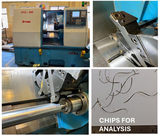
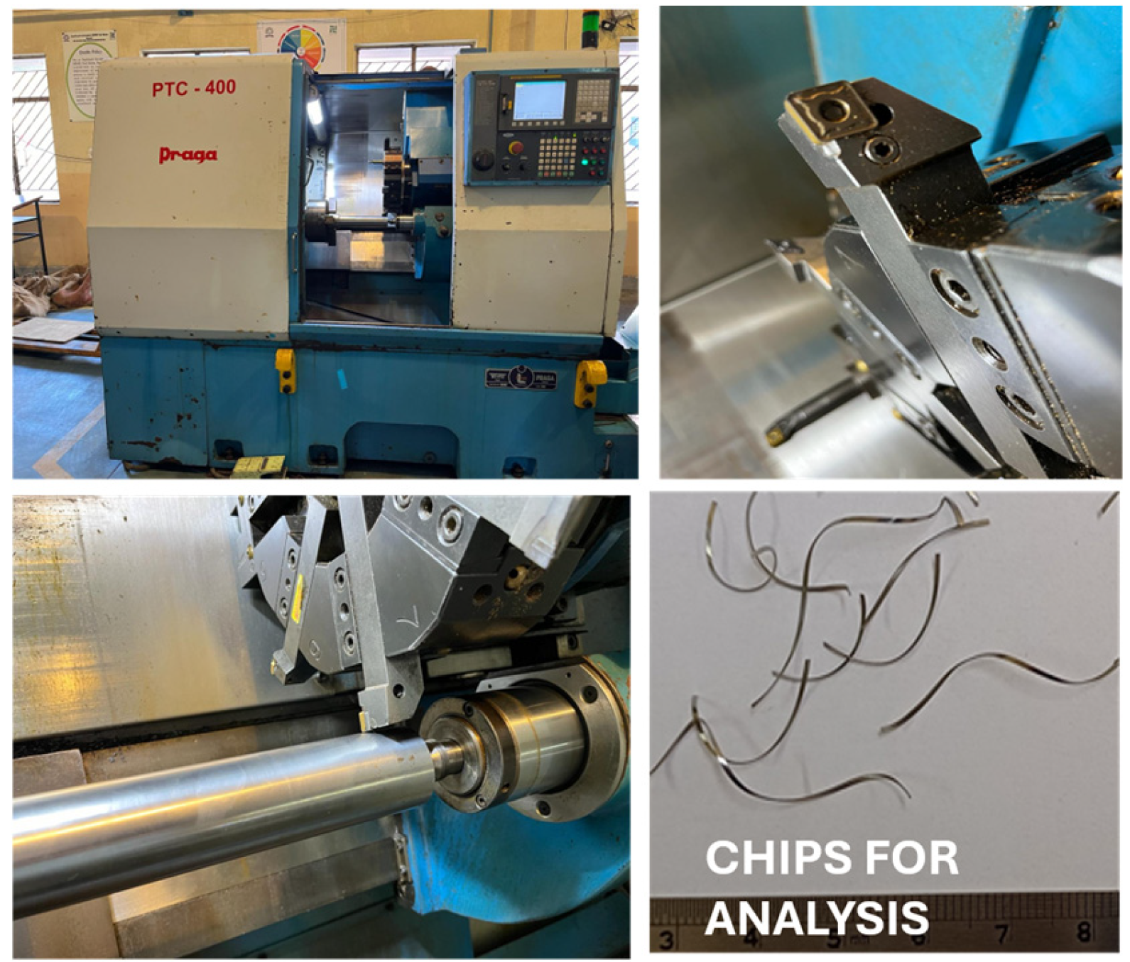
In this experimental work, a cylindrical WP7V workpiece of 230 mm in length and 70 mm in diameter was used for turning operation. The composition of WP7V steel is given in Table 1. The elemental composition was determined by using a handheld XRF analyzer (Make: Olympus Vanta, Japan, Model: V2CA). A CNC lathe machine (Model: PTC 400 PRAGA, Praga Tools Ltd., Secunderabad, India) was used for turning operation. The CNC lathe machine has 7.5 kW power rating and spindle speed of 40 to 4000 RPM (programming control version FANUC series Oi-TC).
Table 1.
Major composition of WP7V steel.
The experiments were performed using a YG 801 PVD-coated (TiAlN) carbide cutting insert (make: YG-1 Co., Ltd. Incheon, South Korea). The insert geometries are as follows: 80° rhombic, approach angle of 95°, 7° clearance angle and 6° negative rake angle. The cutting insert was held with a tool holder (PCLNR 2525 K12). In turning, the cutting parameters, cutting speed (70, 140 and 210 m/min), feed rate (0.05, 0.1 and 0.15 mm/rev), and depth of cut (0.1, 0.15, 0.2 mm), were varied over a range. Dry and wet (flooded) cooling were used for the experiments. Coolant (Mak Sherol BN, Bharat Petroleum, Mumbai India) was mixed in the proportion of 200 mL of coolant in 1 L of water. Taguchi L27 orthogonal array design of experiments was fixed for both dry and flooded lubrication machining conditions. Figure 1 shows the machining process.
Figure 1.
Machining process setup.
The chip reduction coefficient (CRC) and chip morphology (type and color) were studied. Chip thickness was measured by using a digital vernier caliper (Make: Mitutoyo South Asia Pvt. Ltd. New Delhi, India). The CRC was estimated by using the following formula:
where a2 is the cut chip thickness, a1 is the uncut chip thickness, s is the feed rate, and sinφ is the approach angle of the cutting tool, which is 95°.
Turning operation was carried out using the three levels of the machining parameters (speed, feed rate and depth of cut) for both dry and wet conditions using a Taguchi L27 orthogonal array. MINITAB Ver. 19 was used for analysis. The details of the level of machining parameters are given in Table 2.
Table 2.
Level of machining parameters.
3. Results and Discussion
The chip reduction coefficient (CRC) is a dimensionless parameter which serves as an index of plastic deformation in the chip formation process during machining and is indicative of the ease of machining. Lower CRC values (≤1) indicate low plastic deformation and low energy consumption in machining, whereas higher CRC values indicate large shear strain and high energy consumption. WP7V steel is an alloy of chromium, molybdenum, and vanadium and exhibits sufficient abrasive wear resistance. During WP7V steel machining, cutting force and heat generation are significant, which makes the CRC a valuable measure for evaluation of optimal machining parameters in the turning process. In this section, the chip reduction coefficient and the influence of different machining parameters in dry and wet machining environments are discussed. Table 3 shows the estimated results of the chip reduction coefficient (CRC) under different experimental input machining parameters in dry and wet environments.
Table 3.
Chip reduction coefficient (CRC) obtained during machining under dry and wet conditions.
3.1. Chip Reduction Coefficient (CRC) in Dry Machining
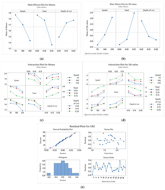
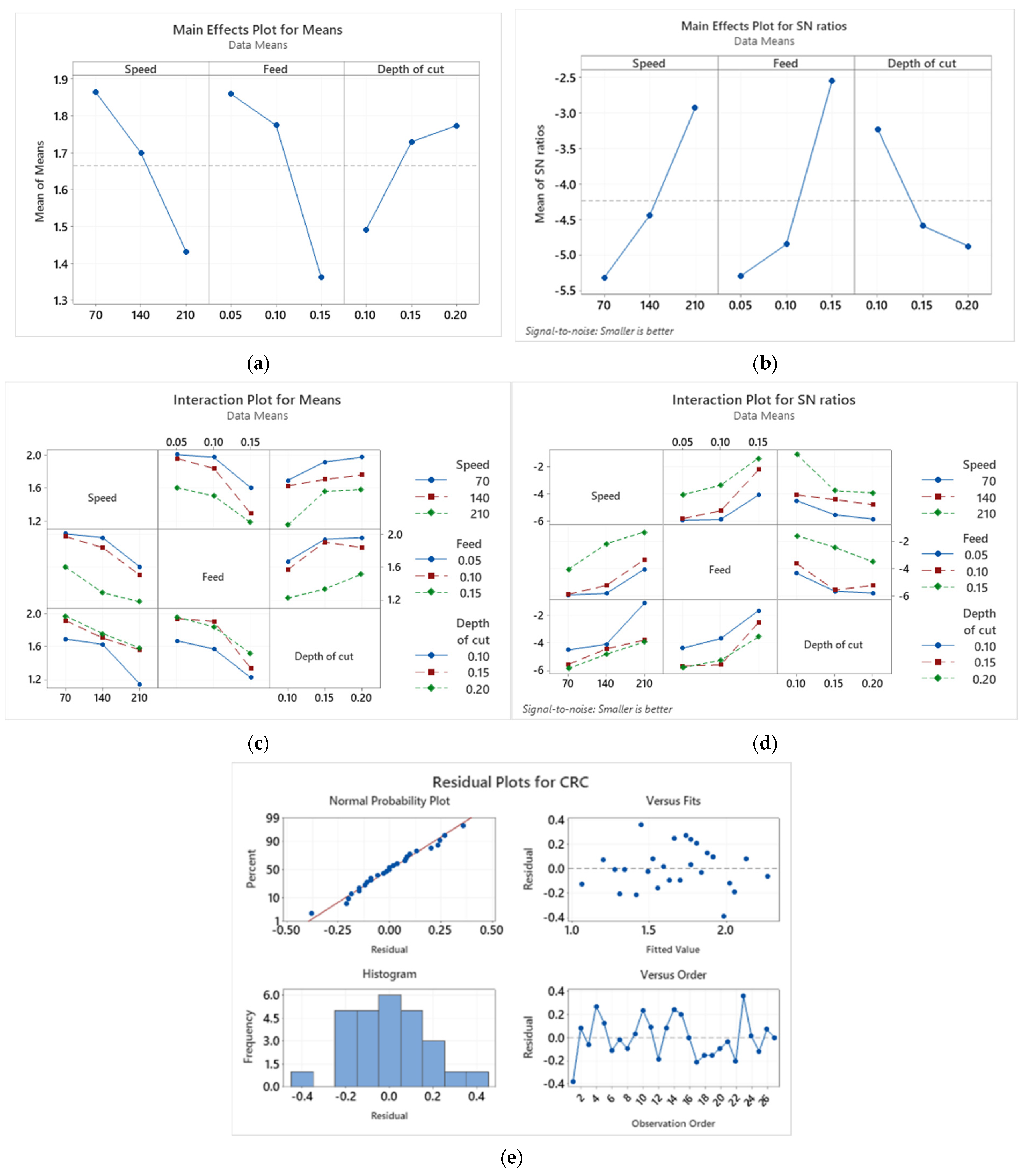
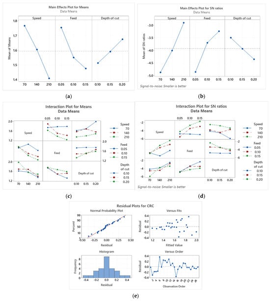
The mean effect plot of means (Figure 2a) shows that the chip reduction coefficient (CRC) reduces from 1.9 at 70 m/min to 1.4 at 120 m/min reflecting the thermal softening of workpiece material, which reduces the shear plane strain and chip thickening. The strain increases due to high speed during machining, but the generated heat also lowers the flow stress of work material and leads to thinner chip formation under dry machining conditions.
Figure 2.
(a) Mean effect plots of means, (b) mean effect plots of SN ratios, (c) interaction plots of means, (d) interaction plots of SN ratios, and (e) residual plots of chip reduction coefficient (CRC) for machining under dry conditions.
The CRC value decreases from 1.8 at the feed rate of 0.05 mm/rev to 1.5 at 0.15 mm/rev, as larger undeformed chip thickness reduces relative deformation. The thicker chips obtained at a higher feed rate resist curling but demonstrate less proportionate thickening due to the probably constrained geometry of the shear zone. There is a slight drop in the CRC value from 1.7 at a depth of cut of 0.1 mm to 1.6 at a 0.2 mm depth of cut. Although the influence of the depth of cut on the CRC is minor, it is consistent. At higher depths of cut, the shear zone expands, and strain distribution also increases.
The main effect plot of the SN ratio (Figure 2b) shows the influence of cutting speed, feed rate and depth of cut on the CRC. The SN ratio increases with the rise in cutting speed, and the CRC reduces because of the thermal softening occurring due to high heat generation at high cutting speed. The moderate feed rate minimizes chip thickening. The higher CRC may be due to the higher strain (shear) of the chips. The depth of cut has the smallest effect on the CRC during machining. The SN ratio drops sharply from −3.0 to −5.5 with the increase in the depth of cut from 0.1 mm to 0.2 mm. The higher depth of cut amplifies plastic deformation and friction, which leads to an increase in the CRC. The smallest CRC was obtained for a cutting speed of 210 m/min, a feed rate of 0.1 mm/rev and a depth of cut of 0.1 mm. This condition promotes the formation of thin and less curled chips.
The interaction plot of the means (Figure 2c) shows that at a low feed rate (0.5 mm/rev), the chip reduction coefficient (CRC) is the greatest for the cutting speed of 70 m/min and decreases gradually with the increase in cutting speed. At higher feed rates, the CRC decreases more abruptly with the increase in cutting speed. The increase in cutting speed leads to the rise in temperature during cutting, which leads to the softening of the work material and the generation of thinner chips; hence a low CRC is obtained. Higher feed rates increase uncut chip thickness and promotes plastic compression ahead of the tool tip. But this effect gets reduced at high cutting speed because the workpiece material becomes softer. At high feed rates, significant interaction exists between cutting speed and feed rate. Under all depth-of-cut conditions, the CRC decreases with the increase in cutting speed.
The non-parallel lines signify a moderate interface between cutting speed and depth of cut. At a large depth of cut (0.2 mm), the CRC value is larger compared with the smaller depth of cut. The CRC value reduces with the rise in feed rate from 0.05 to 0.15 mm/rev. The feed rate and depth of cut combinedly influence the chip formation behavior. In the chip formation mechanism, the feed rate controls chip thickness, and the depth of cut influences chip width. It was also observed during machining that a low feed rate and a high depth of cut tend to produce thin, wide chips. Cutting speed has strong influence on the CRC. The CRC decreases with the increase in cutting speed due to thermal softening, and higher depth of cut compresses the chip more, resulting in a higher CRC value.
From the interaction plot of the SN ratio (Figure 2d), it is observed that the SN ratio improves considerably with cutting speed, as high cutting speed promotes better chip flow and reduces chip compression. A low feed rate results in a high SN ratio. Smaller uncut chip thickness reduces plastic deformation. A moderate depth of cut gives an improved SN ratio. The smallest CRC value is obtained with high cutting speed, a low feed rate and a moderate depth of cut. At high cutting speed, a rise in temperature induces less resistance to shear deformation, and chips become thinner. At a low feed rate, there is a reduction in deformation volume, and chips form easily with lower thickness. A moderate depth of cut results in relaxed shear of chips and also maintains low friction as well as deformation resistance. The non-parallel lines confirm the presence of interactions among the machining parameters. The chip formation mechanism is influenced by thermo-mechanical phenomena (shear deformation, temperature and friction). The residual plot of the CRC is shown in Figure 2e. In the normal probability plot, the points lie close to the straight reference line, which confirms the normal distribution of normals, valid for p-values and confidence intervals of machining parameters. The residual-and-fits plot reveals the random scatter of data points above the zero line and seems a reliable model for prediction of CRC values. Rare higher fits may be due to tool wear and vibration (if any) under dry machining conditions. The bell-shaped histogram plot indicates good orthogonal design of input machining process parameters. The residual vs. orders plot indicates the independent observations of experiments.
From Table 4 it is apparent that the feed rate is the most significant for the smallest chip reduction coefficient, followed by cutting speed, while the depth of cut has the smallest influence on the chip reduction coefficient. Proper feed rate and cutting speed selection during the machining of WP7V steel under dry conditions will help to achieve favorable chip formation and less energy consumption.
Table 4.
Response table for signal-to-noise ratios (dry machining conditions).
The analysis of variance for the SN ratio (Table 5) shows that the feed rate is the most significant (Adj SS value of 38.924 and F-value of 21.48) for the chip reduction coefficient and cutting speed is the second most substantial parameter, with a p-value of 0.002 and an F-value of 14.45. The depth of cut is the least significant factor and has a moderate effect on the CRC. Uncut chip thickness increases at a higher feed rate, and the CRC also increases. The rise in the depth of cut does not affect the CRC value as much as the feed rate or cutting speed, but the cutting force may rise because of this. It is apparent that the interactions of machining parameters (cutting speed, feed rate and depth of cut) are less significant than the individual parameters in determining the CRC during machining. The regression equation for the CRC obtained under dry cutting conditions is shown in Equation (2).
CRC = 2.171 − 0.003081 Speed − 4.975 Feed + 2.819 Depth of cut
Table 5.
Analysis of variance for SN ratios (dry machining).
3.2. Chip Reduction Coefficient (CRC) in Wet Machining
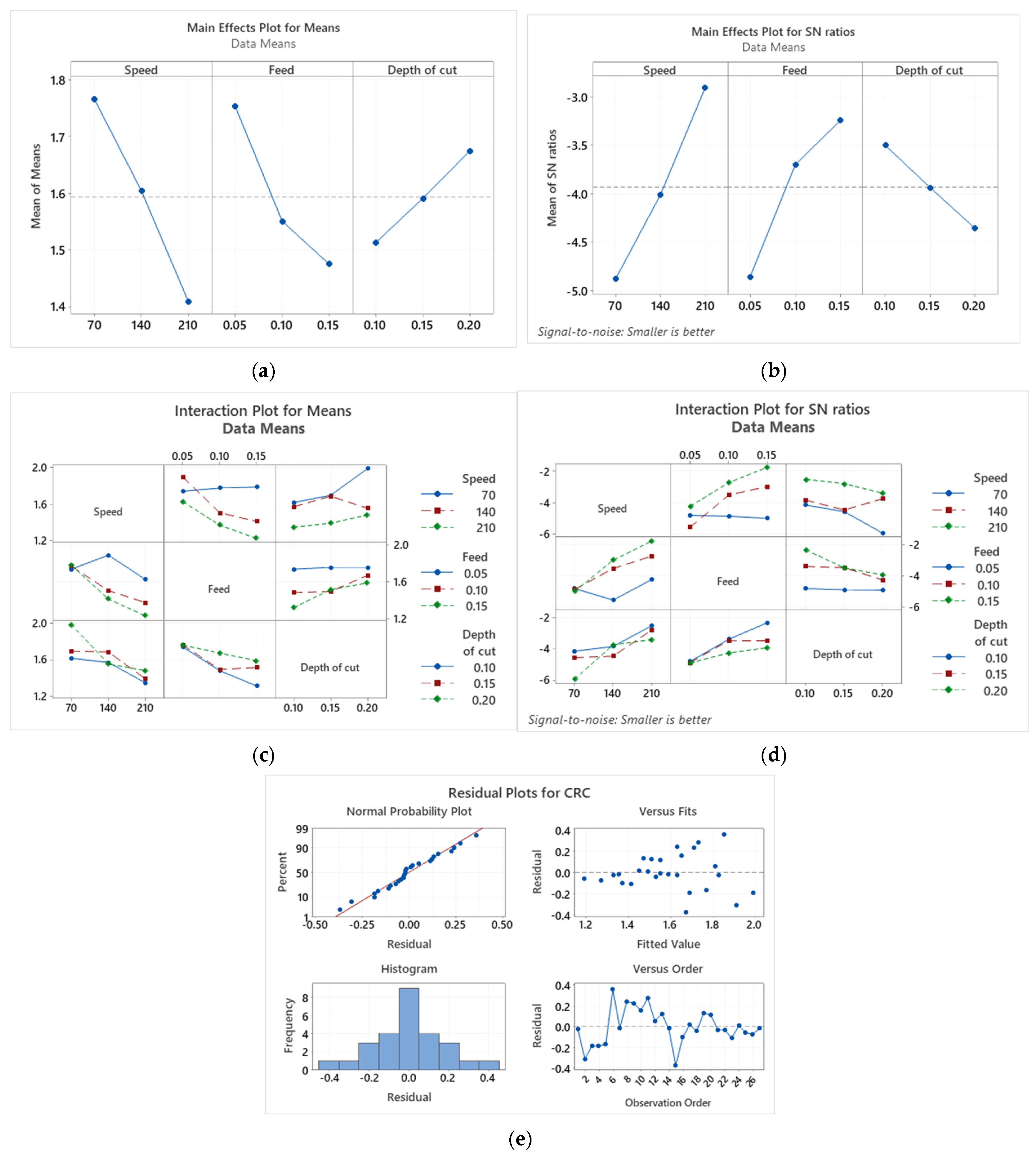
The machining of WP7V steel was performed using a TiAlN–PVD-coated tool under wet lubrication conditions. The machining parameters used were the same for machining under dry conditions. The interactions of the machining process parameters under the wet lubrication conditions were analyzed in relation to the chip reduction coefficient. From Figure 3a, it is observed that the mean response reduces from 1.76 to 1.4 with the change in cutting speed from 70 to 210 m/min. Wet lubrication dissipates heat generated during machining effectively and reduces friction. A moderate decline in the CRC was also observed (1.7 to 1.5) with an increase in feed rate from 0.05 to 0.15 mm/rev. A higher feed rate increases undeformed chip thickness and helps to produce thinner cut chips.
Figure 3.
(a) Mean effect plots of means, (b) mean effect plots of SN ratios, (c) interaction plots of means, (d) interaction plots of SN ratios, and (e) residual plots of chip reduction coefficient (CRC) for machining under wet conditions.
The SN ratio increases considerably with cutting speed (−4.9 at 70 m/min to ≈−3.0 at 210 m/min), and the CRC at high cutting speed decreases (Figure 3b). Wet lubrication reduces friction and promotes better chip flow. The steep slope indicates that cutting speed is a more influential machining parameter for the CRC. A higher feed rate helps to lower the CRC value and promotes better chip formation due to the effective shearing mechanism during chip formation. With the increase in the depth of cut, the SN ratio decreases and the CRC increases. More compression and the thickening of chips take place even with lubrication. The observations also suggest that to achieve a low CRC, a low depth of cut is preferred during machining. It is observed from the SN plot that the smallest CRC value is obtained under the favorable machining conditions of a cutting speed of 210 m/min, a feed rate of 0.15 mm/rev and a depth of cut of 0.1 mm.
Figure 3c depicts the interaction plot of means. The cutting speed–feed rate interaction produces non-parallel lines, and at low speed (70 m/min), the CRC value increases distinctly with feed, maybe due to improper heat dissipation and ductile chip formation. At low speed, deeper cutting enhances the CRC values because of a greater rubbing of chips on the rake face. Efficient cooling helps to reduce the high-speed conjunction. The interaction of feed rate and depth of cut have minimum impact on the CRC. A low level of feed rate and a low depth of cut result in the lowest CRC (1.0–1.2). In the SN ratio interaction plot (Figure 3d), a strong interaction effect is observed for cutting speed–feed rate on the CRC. At a lower speed and feed-rate range, the coolant efficiently controls deformation. A high feed rate influences the SN ratio sharply at low speed due to unstable chips, but at high speed (210 m/min), recovery takes place with thermal homogenization. A low depth of cut (0.1 mm) increases SN values for all speeds by reducing chip–tool interface friction variations. The interaction of feed rate and depth of cut has negligible impact on the CRC. Low feed rate and depth of cut result in the peak SN ratio value (≈−2) by minimizing the variation in the CRC. The residual plots for the CRC are shown in Figure 3e. The normal distribution of residuals and alignments are verified from the normal probability plot, and the minor slope may be due to thick chip formation under low-speed and high-feed-rate conditions.
Higher SN ratio values (less negative) indicate low CRC variation and better process stability (Table 6). Cutting speed, feed rate and depth of cut rank first, second, and third respectively in relation to chip formation. CRC values reduce with the increase in speed and feed rate. High speed results in a rise in temperature, and a lower feed rate minimizes the deformation zone during chip formation. In wet machining, the cooling and lubricating action minimizes thermal effects and friction, making feed rate the dominant parameter controlling chip geometry and deformation. The delta value of the depth of cut (0.856) is the lowest, which indicates that the coolant eases the friction condition in wet machining.
Table 6.
Response table for signal-to-noise ratios (wet machining).
Table 7 shows the statistical analyses (ANOVA for the SN ratio) of machining process parameters on the chip reduction coefficient (CRC). Low error (0.03244) confirms good precision under wet lubrication conditions. The coolant stabilizes chip formation during wet machining. Cutting speed is a dominating machining parameter (Adj SS = 0.5758, F = 17.75 and p = 0.000). The CRC value gets reduced at high speed due to the thermal softening of the workpiece, and better lubrication reduces friction at the chip–tool interface. The feed rate affects uncut chip thickness and enhances deformation at higher values despite wet cooling. The depth of cut has minor role under wet machining conditions (Adj SS = 0.1178, F = 3.63 and p = 0.069). The regression equation for the CRC obtained for wet cutting conditions is shown in Equation (3).
CRC = 1.987 − 0.002555 Speed − 2.789 Feed + 1.618 Depth of cut
Table 7.
Analysis of variance for SN ratios (wet machining).
3.3. Chip Morphology with SEM
Chip morphology, which includes shape, size, segmentation, and color is an indicator of machinability. Without stopping production, the chips formed during machining process can be studied, and tool performance, machined surface quality, and stability during cutting can be assessed. Temperature generation during machining can be estimated by observing the color of the chips; in turn that helps to justify the appropriate tool and cutting conditions. The cutting parameters, such as cutting speed, feed rate and depth of cut, also influence chip shapes and forms.
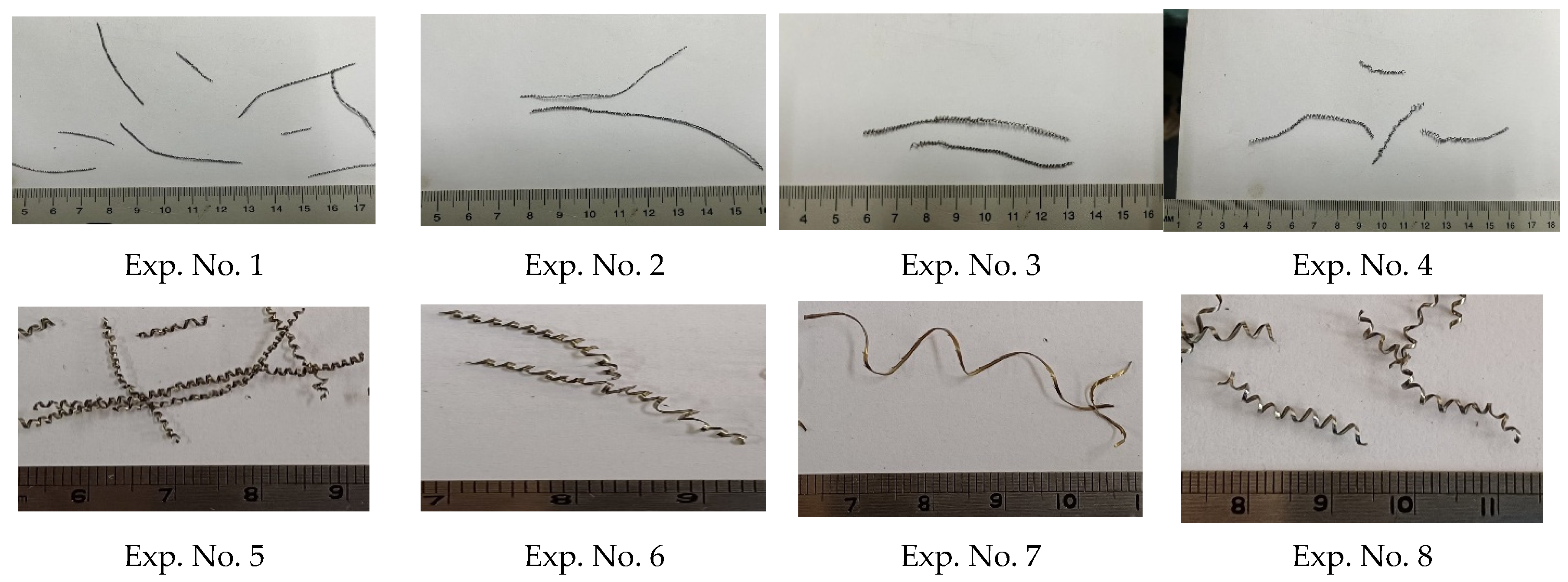
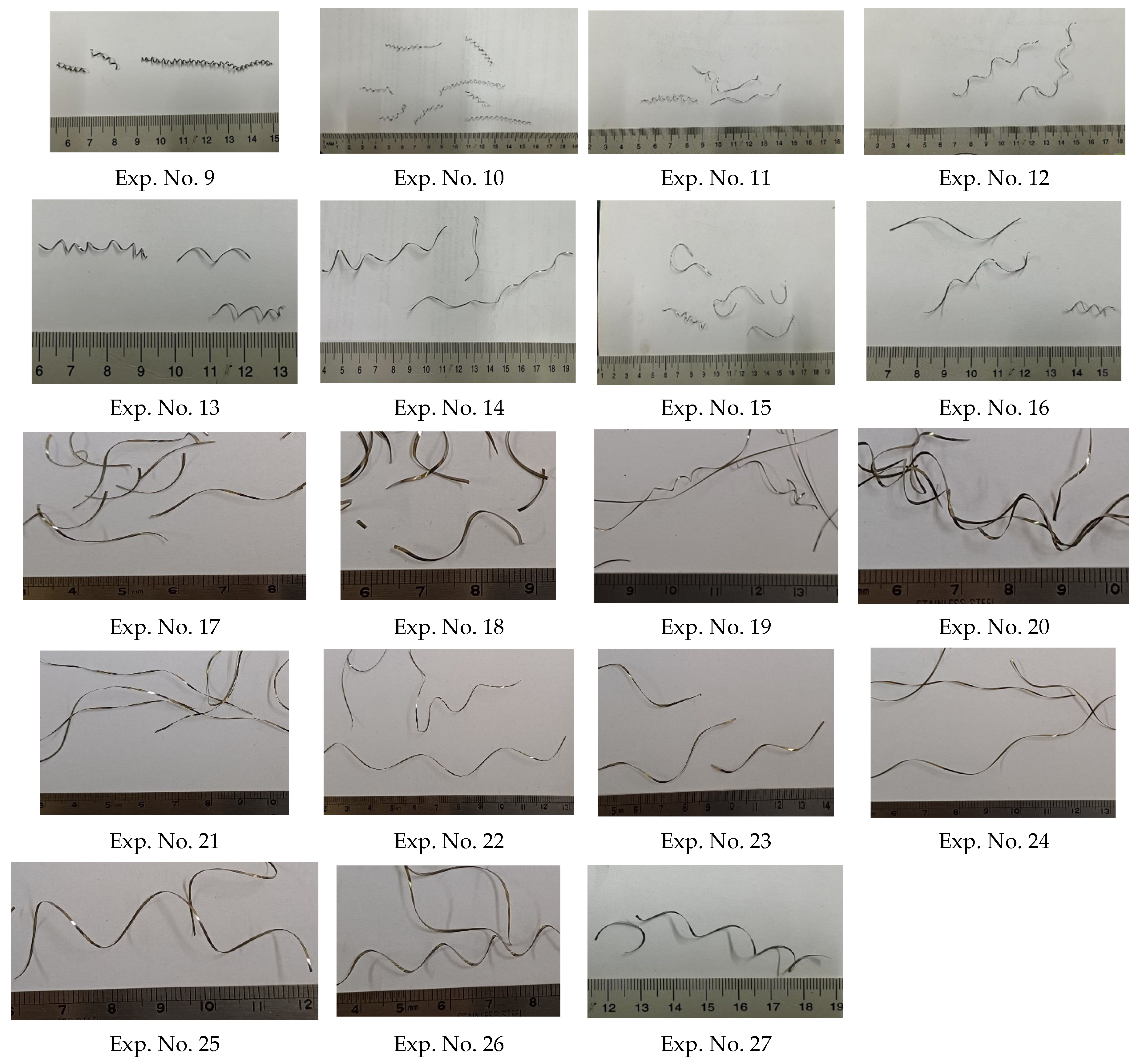
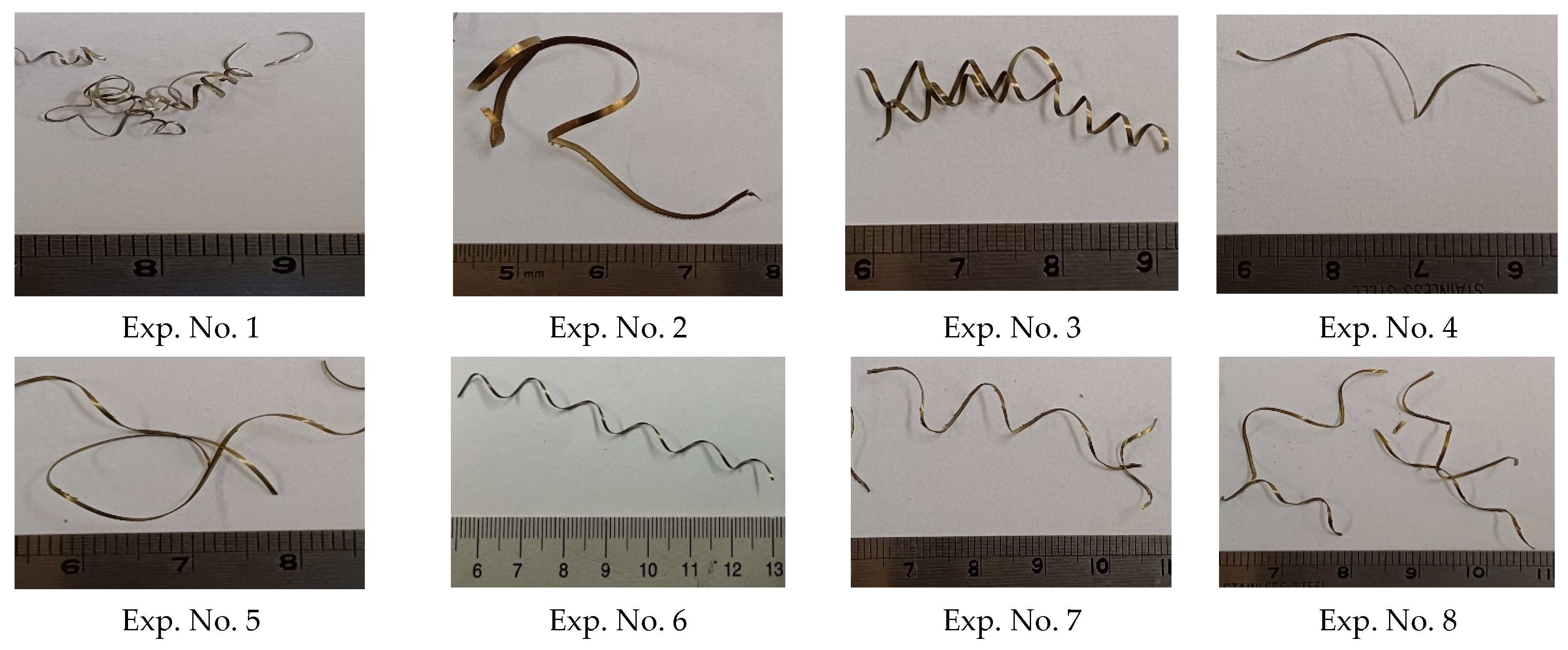
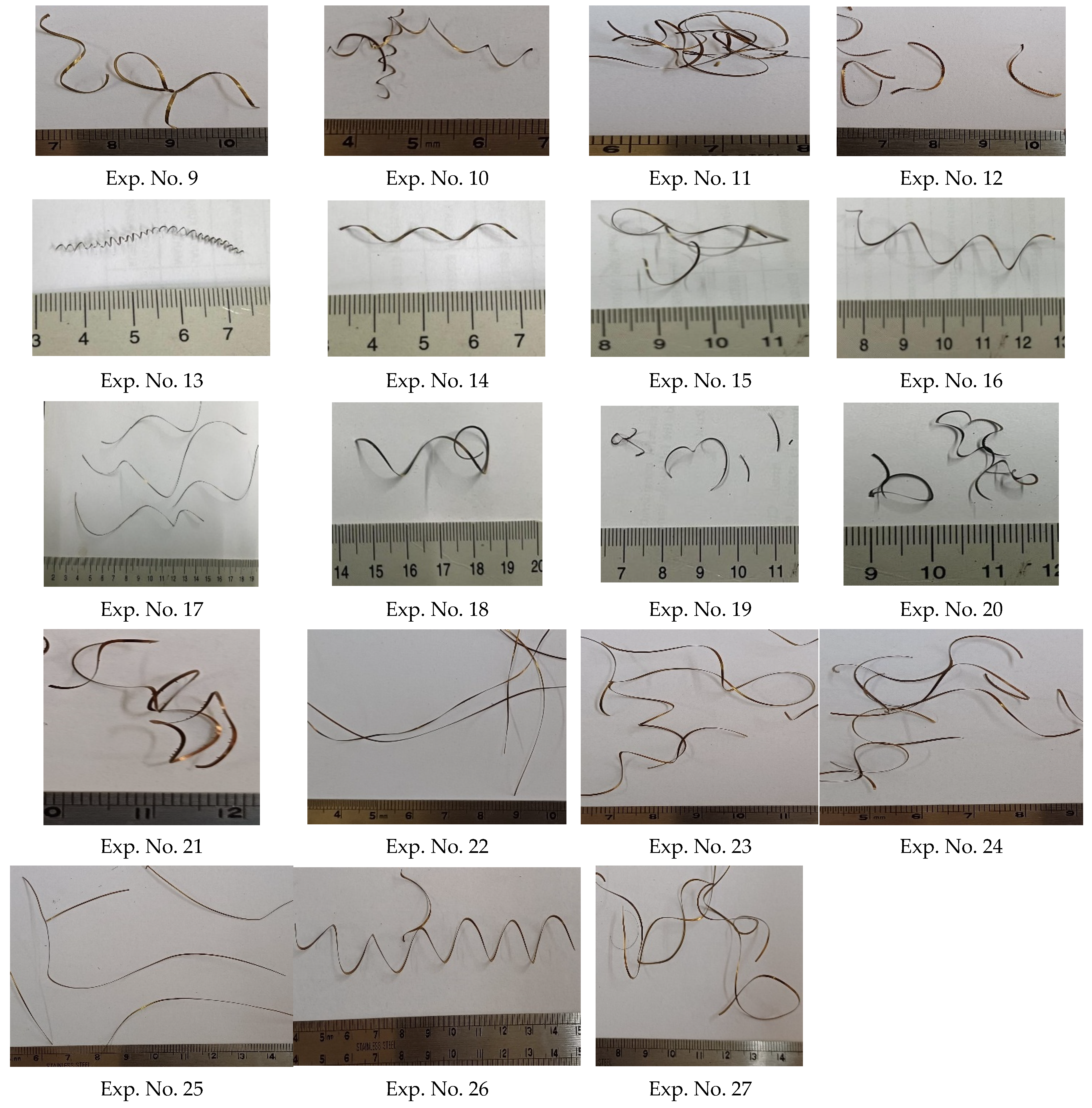
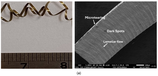
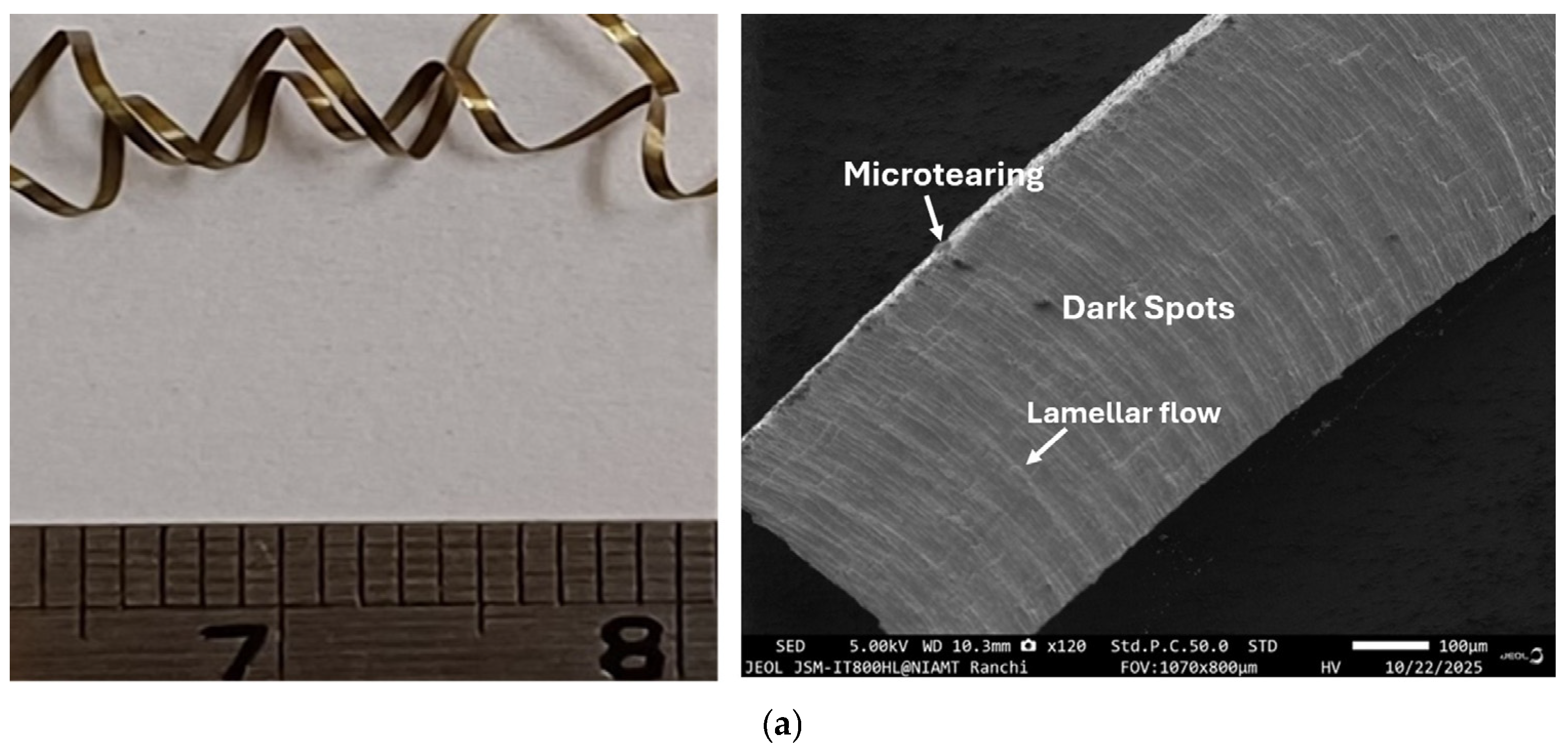
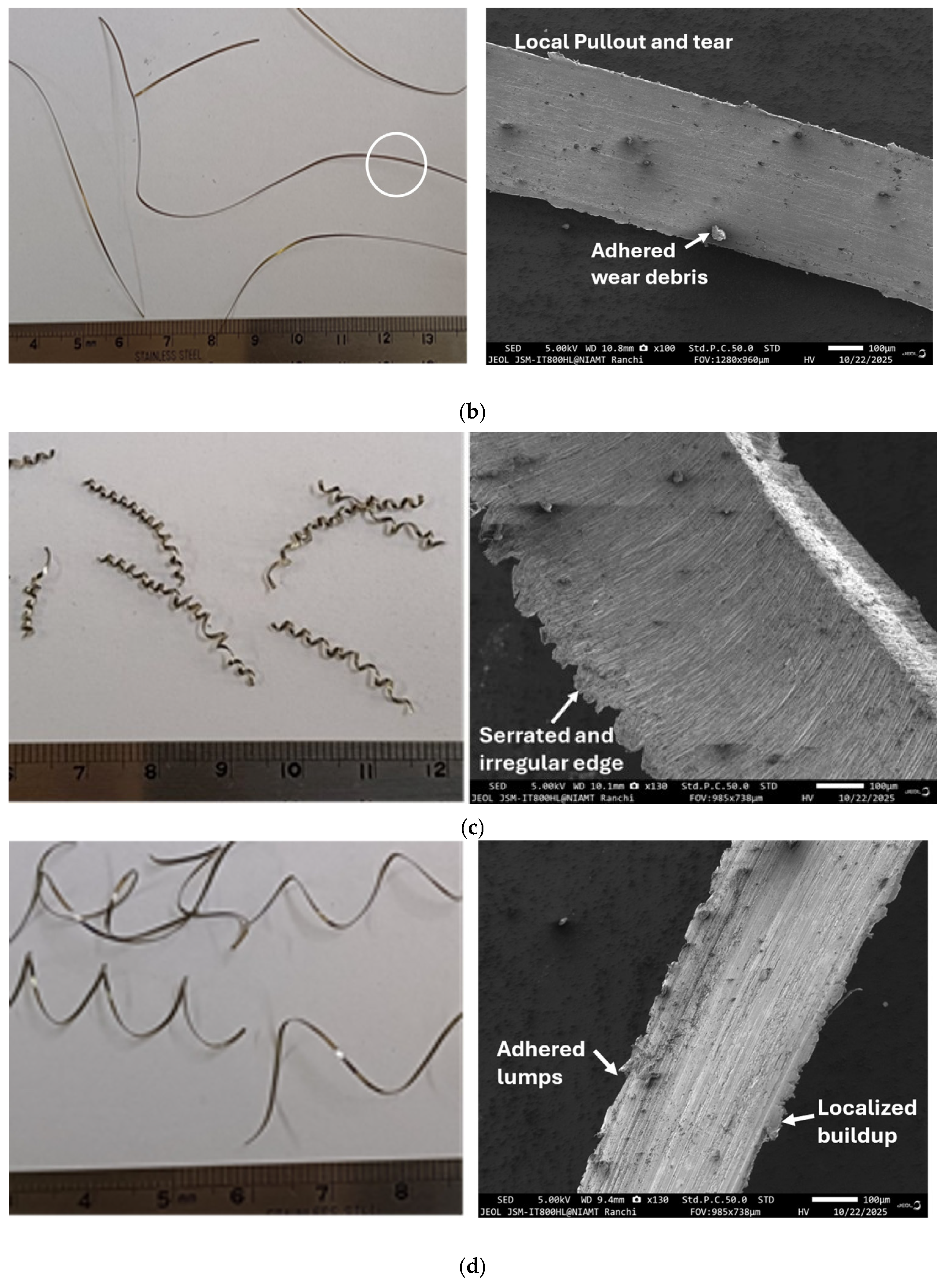
The types of chips formed during the machining of WP7V steel with different machining parameters under wet and dry conditions are shown in Appendix A and Appendix B respectively (Figure A1 and Figure A2). Under dry machining conditions, most of the chips formed are long and less curved. Semi-segmented and moderately curved chips were formed at high cutting speeds of 140 and 210 m/min. Chips obtained for the feed rate of 0.05 mm/rev are short and open “C” types, which are favorable for easy disposal and imply stable and superior machining conditions. In wet machining environments, chips obtained are mostly continuous and medium-spiral in nature at low cutting speed and medium–high feed rates. Considerably serrated chips were observed at low speed, moderate feed rates and high depths of cut (exp. No. 6, wet). At low cutting speed, there is high friction at the chip–tool interface and possible adherence of the material to the chip edge. The color of chips obtained during machining is a good indicator of heat generation during machining and the amount of quenching that takes place in dry and wet machining environments. The colors of chips are shiny metallic for all cases of dry and wet machining. This indicates that heat generation is not so high for color change and machining conditions are favorable. An in-depth analysis of the chips with the highest and lowest CRCs was carried out with SEM analysis. The SEM photographs of chips obtained with the highest and lowest CRC values under dry and wet lubrication are shown in Figure 4.
Figure 4.
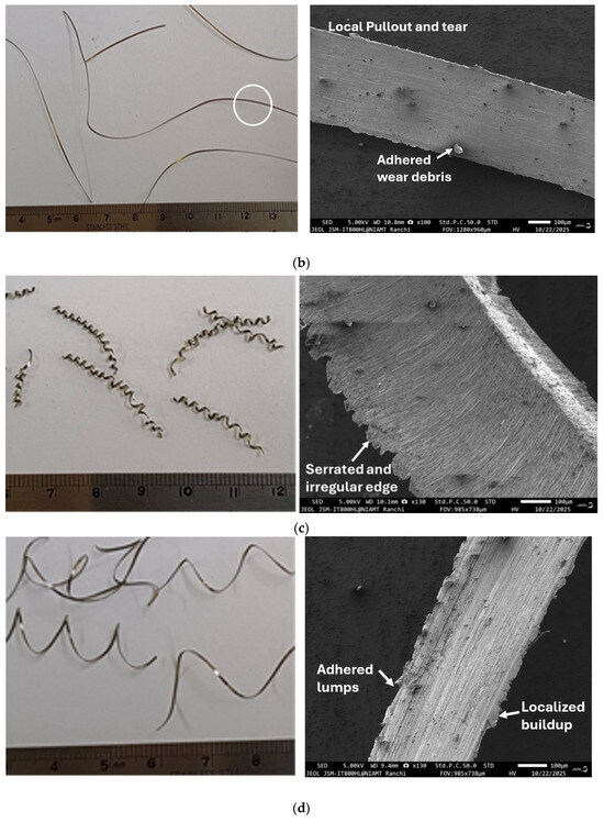
Chip forms and SEM images of chips machined under different conditions: (a) cutting speed = 70 m/min, feed rate = 0.05 mm/rev, and depth of cut = 0.2 mm [dry]; (b) cutting speed = 210 m/min, feed rate = 0.15 mm/rev, and depth of cut = 0.1 mm [dry]; (c) cutting speed = 70 m/min, feed rate = 0.1 mm/rev and depth of cut = 0.2 mm [wet]; (d) cutting speed = 210 m/min, feed rate = 0.15 mm/rev and depth of cut = 0.1 mm [wet].
Figure 4a shows the chips obtained during machining at a cutting speed of 70 m/min, a feed rate of 0.05 mm/rev, and a depth of cut of 0.2 mm under dry conditions along with the SEM image. Under these conditions, long, continuous chips without catastrophic fracture (stable chip formation) with sheared and laminated surfaces are observed. Distinct flow lines and parallel ridges indicate significant plastic deformation and effect of friction at chip–tool interfaces. Because of shear deformation, substantial directional chip surfaces, along with grooves, are obtained. Possibly due to the heat generated, the microtearing of chips takes place, and small dark pits and irregular spots (scattered in nature) can be observed on the chips following dry machining. Microtearing and the adhesion of abrasive debris on chip surfaces during dry machining occur due to a blend of severe friction, high temperature, and unstable interaction at the tool–chip interface. The lower edge of the chip is rough and uneven due to work hardening and the curling of chips. Because of the wear resistance and thermal stability property of the PVD-coated WC tool, chip stability takes place. The continuous and ribbon-like chips are indicative of the periodic process instability at the cutting zone.
Figure 4b shows the chips formed following dry machining with a 210 m/min cutting speed, a feed rate of 0.15 mm/rev, a depth of cut 0.1 mm and a CRC value of 0.937. The chips are continuous, long and smooth and present some adhered particles and few pullouts. This indicates plastic shear flow of the material rather than brittle fracture. The SEM image shows that wear debris adheres to the chip surface, and dark pits and minor damage of the surface can also be observed. The chip morphology changes at high cutting speed due to the thermo-mechanical effect and severity of contact conditions at the chip–tool interface.
During wet machining, reduced temperature and lower friction are expected compared with dry machining. But as an exception, in the machining of WP7V steel, chips experience significant shear, and the formed chips are highly serrated, with irregular edges and rough fractures (Figure 4c). There may be a possibility of change in the chip–tool interface contact environment because of lubrication and cooling, and the chip flow appears to be severe. The serrated edge and irregularity at boundary regions indicate that the chips form under fluctuating deformation conditions rather than smooth flow. In comparison to the chips formed in dry machining, slightly disrupted chip morphology at the edges is found. This may happen due to irregular chip curling, thermal softening, or some kind of dynamic changes in cutting forces during the wet cutting process. Moreover, serrated irregular chips in wet machining are primarily the result of thermo-mechanical instability in the shear zone, which is strongly influenced by the presence of cutting fluid [20]. The lowest CRC value (1.138) was obtained during the machining of WP7V die steel in a wet environment. Figure 4d shows that the chip is elongated and more uniform with a smooth surface in the central area and a rough surface at the edge. Clear flow lines are visible in the SEM image, and this indicates substantial plastic deformation. Some lumps are found to adhere on the chips. The lumps and torn-out materials indicate localized sticking or possible metal transfer during the cutting process. In machining in wet environments, the coolant helps to reduce heat and friction, but hard materials like WP7V steel still undergo high shear stress. The smooth surface of the chips is due to improved lubrication, whereas the rough edges indicate irregular adhesion and tearing near the chip edge areas. Compared with the chips obtained with dry machining, chips with less damage are obtained with wet machining because of the positive contribution from the coolant.
4. Conclusions
This study systematically evaluated the machinability of WP7V die steel under dry and wet conditions with a TiAlN-coated carbide tool. The chip reduction coefficients were studied to establish optimal conditions contributing to improved machining:
- i.
- A moderate feed rate optimizes chip thickening, and the depth of cut has the smallest effect on the chip reduction coefficient (CRC) in the dry machining process. With a high depth of cut, the increase in friction and plastic deformation leads to an increase in the CRC. Higher cutting speed (210 m/min), feed rate (0.1 mm/rev) and depth of cut (0.1 mm) produce the smallest CRC and less curled chips. The feed rate is the most significant parameter for the smallest CRC, followed by cutting speed, in dry machining.
- ii.
- In wet machining, cutting speed (210 m/min), feed rate (0.15 mm/rev), and depth of cut (0.1 mm) are conducive for the smallest CRC. Wet machining stabilizes chip formation mechanisms compared with dry machining.
- iii.
- Under dry machining conditions, the chips formed are mostly long and less curled. Chips are continuous and medium-spiral in nature in wet machining.
- iv.
- Long and continuous chips without catastrophic failure with shear and laminated surfaces were obtained at low cutting speed. In dry machining, chips carry thermo-mechanical loading at the chip–tool interface, as shown by chips with debris adhering on the surface and pullouts.
- v.
- In wet machining, serrated chips with irregular edges and rough fractures were observed, and this is probably due to a change in the conditions at the chip–tool interface.
- vi.
- It is expected that discontinuous chips are favorable for easy disposal. However, continuous-chip formation promotes stable machining. Suitable chip-breaking mechanisms can be adopted for the effective chip breaking of continuous chips.
Author Contributions
Conceptualization: M.K.G. and R.D.; Methodology: M.K.G. and R.D.; Software: M.K.G.; Validation: M.K.G. and R.D.; Investigation: M.K.G.; Resources: M.K.G.; Data curation: M.K.G. and R.D.; Writing—original draft preparation: M.K.G.; Writing—review and editing: M.K.G. and R.D.; Supervision: R.D. All authors have read and agreed to the published version of the manuscript.
Funding
No external funding was used for supporting this research work.
Institutional Review Board Statement
Not applicable.
Informed Consent Statement
Not applicable.
Data Availability Statement
The original contributions presented in this study are included in the article. Further inquiries can be directed to the corresponding author.
Acknowledgments
The authors acknowledge the Jharkhand Government Tool Room, Ranchi, Jharkhand, India, for providing the experimental facility for machining and the Central Instrument Facility, NIAMT, Ranchi, Jharkhand, India, for providing the SEM facility.
Conflicts of Interest
The authors declare no conflicts of interest.
Appendix A. Chips Obtained with Wet Machining
Figure A1.
Figures of chips obtained from wet machining.
Appendix B. Chips Obtained with Dry Machining
Figure A2.
Figures of chips obtained from dry machining.
References
- Pacella, M. A new low-feed chip breaking tool and its effect on chip morphology. Int. J. Adv. Manuf. Technol. 2019, 104, 1145–1157. [Google Scholar] [CrossRef] [Scilit]
- Şap, E.; Usca, U.A.; Gupta, M.K.; Kuntoğlu, M. Tool wear and machinability investigations in dry turning of Cu/Mo-SiCp hybrid composites. Int. J. Adv. Manuf. Technol. 2021, 114, 379–396. [Google Scholar] [CrossRef] [Scilit]
- Emir, E.; Özdemir, B.; Bahçe, E. Experimental investigation and FEM analysis of chip morphology in the turning of ASTM F-75 CoCrMo alloy. Sigma J. Eng. Nat. Sci. 2024, 42, 679–691. [Google Scholar] [CrossRef] [Scilit]
- Wang, Q.; Zhao, Y.; Zhang, C.; Xu, H.; Xu, B.; Wei, Z.; Kang, C.; Li, D.; Guo, J. Prediction and formation mechanism of serrated chips in cutting of SA508–3 steel under enhanced cooling and lubrication environments. Tribol. Int. 2024, 200, 110053. [Google Scholar] [CrossRef] [Scilit]
- Selvakumar, S.J.; Raj, R.S. Tribological characteristics of SiALON ceramic inserts during sustainable machining of Inconel 625 based on comprehensive chip morphology analysis. Wear 2025, 562–563, 205626. [Google Scholar] [CrossRef] [Scilit]
- Singh, B.K.; Roy, H.; Mondal, B.; Roy, S.S.; Mandal, N. Measurement of chip morphology and multi criteria optimization of turning parameters for machining of AISI 4340 steel using Y-ZTA cutting insert. Measurement 2019, 142, 181–194. [Google Scholar] [CrossRef] [Scilit]
- Wang, B.; Liu, Z.; Cai, Y.; Luo, X.; Ma, H.; Song, Q.; Xiong, Z. Advancements in material removal mechanism and surface integrity of high-speed metal cutting: A review. Int. J. Mach. Tools Manuf. 2012, 166, 103744. [Google Scholar]
- Uysal, A.; Jawahir, I.S. Analysis of slip-line model for serrated chip formation in orthogonal machining of AISI 304 stainless steel under various cooling/lubricating conditions. J. Manuf. Process. 2021, 67, 447–460. [Google Scholar] [CrossRef] [Scilit]
- Khatai, S.; Kumar, R.; Sahoo, A.K.; Panda, A. Investigation on tool wear and chip morphology in hard turning of EN 31 steel using AlTiN-PVD coated carbide cutting tool. Mater. Today Proc. 2022, 59, 1810–1816. [Google Scholar] [CrossRef] [Scilit]
- Mohan, R.; Harshavardhana, N.; Chaudhari, M.; Jeyanthi, S.; Abimannan, G. Analysis on surface finish and chip morphology during dry turning process. Mater. Today Proc. 2021, 46, 999–1002. [Google Scholar] [CrossRef] [Scilit]
- Rastorguev, D.; Sevastyanov, A. Diagnostics of chip formation and surface quality by parameters of the main drive current in the hard turning. Mater. Today Proc. 2019, 19, 1845–1851. [Google Scholar] [CrossRef] [Scilit]
- Özdemir, B.; Bahçe, E.; Aksungur, S.; Çakir, M.C. Monitoring chip color change in Ti6Al4V alloy milling and investigating the effects of cooling/lubrication on chip morphology. J. Manuf. Process. 2024, 124, 1092–1101. [Google Scholar] [CrossRef] [Scilit]
- Das, S.R.; Panda, A.; Dhupal, D. Hard turning of AISI 4340 steel using coated carbide insert: Surface roughness, tool wear, chip morphology and cost estimation. Mater. Today Proc. 2018, 5, 6560–6569. [Google Scholar] [CrossRef] [Scilit]
- Bag, R.; Panda, A.; Sahoo, A.K.; Kumar, R. Cutting tools characteristics and coating depositions for hard part turning of AISI 4340 martensitic steel: A review study. Mater. Today Proc. 2020, 26, 2073–2078. [Google Scholar] [CrossRef] [Scilit]
- Abidi, Y. Relationship between surface roughness and chip morphology when turning hardened steel. Prod. Eng. Arch. 2020, 26, 92–98. [Google Scholar] [CrossRef] [Scilit]
- Parida, A.K.; Maity, K. Experimental investigation on tool life and chip morphology in hot machining of Monel-400. Eng. Sci. Technol. Int. J. 2018, 21, 371–379. [Google Scholar] [CrossRef] [Scilit]
- Ma, K.; Liu, Z.; Wang, B.; Song, Q.; Cai, Y. How does the uncut chip thickness affect the deformation states within the primary shear zone during metal cutting? Int. J. Mach. Tools Manuf. 2024, 199, 104161. [Google Scholar] [CrossRef] [Scilit]
- Makhesana, M.A.; Patel, K.M.; Bagga, P.J. Evaluation of surface roughness, tool wear and chip morphology during machining of nickel-based alloy under sustainable hybrid nanofluid-MQL Strategy. Lubricants 2022, 10, 315. [Google Scholar] [CrossRef] [Scilit]
- Gupta, M.K.; Das, R. Machinability study of WP7V die steel using Uncoated and Coated Carbide tools under a dry environment. J. Technol. 2024, 12, 491–503. [Google Scholar]
- Kolomy, S.; Slany, M.; Doubrava, M.; Sedlak, J.; Zouhar, J.; Rehorek, L. Comparative analysis of machinability and microstructure in LPBF and conventionally processed M300 maraging steel. Sci. Rep. 2025, 15, 35980. [Google Scholar] [CrossRef] [Scilit] [PubMed]
- Das, A.; Mohapatra, S.; Gajrani, K.K.; Das, S.R.; Patel, S.K. Comparative performance evaluation between HSN2-TiAlxN and TiCN coated carbide tools in hard turning of AISI D6 steel. Proc. Inst. Mech. Eng. Part B J. Eng. Manuf. 2025, 239, 350–365. [Google Scholar] [CrossRef] [Scilit]
- Sousa, V.F.C.; Silva, F.J.G. Recent advances in turning processes using coated Tools—A comprehensive review. Metals 2020, 10, 170. [Google Scholar] [CrossRef] [Scilit]

Disclaimer/Publisher’s Note: The statements, opinions and data contained in all publications are solely those of the individual author(s) and contributor(s) and not of MDPI and/or the editor(s). MDPI and/or the editor(s) disclaim responsibility for any injury to people or property resulting from any ideas, methods, instructions or products referred to in the content. |
© 2026 by the authors. Licensee MDPI, Basel, Switzerland. This article is an open access article distributed under the terms and conditions of the Creative Commons Attribution (CC BY) license.