


Abstract
Electric vehicles (EVs) pose electromagnetic compatibility (EMC) and electromagnetic interference (EMI) challenges that span sub-hertz traction currents to multi-gigahertz radiated emissions. This paper combines a narrative review of 260 publications (1992–2026) with an exploratory case study. The review traces the evolution of EV EMC research, emission and coupling mechanisms, mitigation techniques and the standards framework, and it identifies a standardization gap for heavy-duty platforms. The case study characterizes the near-field electric field of a single 130 kW electric bus under five operating conditions (1 Hz–10 MHz, one acquisition each), supplemented by repeated electric- and magnetic-field recordings during charging (1–150 kHz) referenced to the de-energized vehicle. Below about 1 kHz the spectra are dominated by an instrument-limited plateau that cannot be attributed to the vehicle. During charging, an electric-field line pair at 57.5 and 115.5 kHz rose six- to eightfold above the reference and was reproducible to within ±3% in six recordings; the estimated exposure ratios remained below the ICNIRP general-public reference levels. Key open challenges, research opportunities and mitigation strategies for heavy-duty EV EMC are identified.
1. Introduction
With carbon dioxide emissions reaching critically high levels, the transportation sector is undergoing a fundamental shift towards more environmentally sustainable options. Electric vehicles (EVs) are becoming a central part of this ambition and are more prevalent than ever. Driven by strong adoption policies, electric car sales were projected to exceed 20 million in 2025, more than one-quarter of all new cars sold worldwide, and 40% of sales by 2030 [1]. However, with this advancement, several issues arise from the dense and powerful electric and electronic architecture of modern EVs, creating a complex challenge: ensuring Electromagnetic Compatibility (EMC) and avoiding hazardous electromagnetic interferences (EMIs) [2,3,4]. Modern EVs, including Battery Electric Vehicles (BEVs), Plug-in Hybrid Electric Vehicles (PHEVs), and Hybrid Electric Vehicles (HEVs), incorporate high-voltage, high-power electronic systems that operate at elevated switching frequencies. These systems—including traction inverters [5,6], DC-DC converters [4,7], on-board chargers (OBCs) [8,9], and emerging Wireless Power Transfer (WPT) technologies [10,11]—act as potent sources of EMI. As demonstrated by Silva and Aragón [2] and Guttowski et al. [3], ensuring EMC is paramount not only for the reliable operation of the vehicle’s internal electronic control units (ECUs) but also for the safety of human occupants and bystanders exposed to Electromagnetic Fields (EMF). The literature reveals a growing concern regarding both low-frequency magnetic fields (H-fields) generated by high traction currents [12,13,14] and high-frequency electric fields (E-fields) resulting from rapid voltage transitions (dv/dt) in wide-bandgap semiconductor devices [15,16,17].
These emissions have the potential to interfere with the electrical grid and other local electric and electronic devices, causing degradation in radio performance and, in worse cases, the compromise of safety-critical systems of EVs, as reviewed by [18]. Several studies, such as [19,20,21,22], investigated the generation and propagation of these emissions from both EVs and charging stations causing power quality and distortion and stability issues especially in low-voltage and DC grids. Furthermore, with the advent of autonomous driving features and vehicle-to-everything (V2X) communication, the need for a pristine electromagnetic environment has become more critical than ever [23,24]. The International Commission on Non-Ionizing Radiation Protection (ICNIRP) has established exposure guidelines that serve as the primary safety benchmark, while the International Special Committee on Radio Interference (CISPR) provides emission limits for vehicle-level and component-level testing [25,26,27,28].
This review article aims to present a structured review of the EV EMC/EMI research landscape for the past three decades and integrate this historical review of the field’s evolution with novel empirical data. The objectives are threefold: (1) to synthesize the temporal evolution of EV EMC research from 1992 to 2026 (Section 4.1); (2) to present an exploratory case study that characterizes the near-field emissions of a heavy-duty electric bus under different operating conditions; and (3) to identify the key open challenges and research opportunities, and to review the mitigation techniques that address them.
The specific contributions of this paper are fivefold:
First, it consolidates three decades of EV electromagnetic research into a synthesis organized around four cross-cutting research themes rather than by vehicle subsystem, which makes explicit where the evidence base is mature and where it remains thin.
Second, it reports an exploratory near-field dataset for a 130 kW heavy-duty electric bus measured in service under five operating conditions, supplemented by repeated electric- and magnetic-field recordings during charging referenced to the de-energized vehicle, and it identifies which spectral features can and cannot be attributed to the vehicle.
Third, it evaluates those measurements against the ICNIRP general-public reference levels on a frequency-resolved basis rather than against a single fixed limit, showing that the estimated exposure ratios remain below the applicable levels, with the explicit caveat that this estimate constitutes a margin rather than formal weighted-peak compliance.
Fourth, it draws the mitigation literature into a single quantified comparison of effective band, reported attenuation, volume and efficiency penalty, and relative cost, and reads that comparison against CISPR 12, CISPR 25 and UN Regulation No. 10 to identify the dynamic-drive and megawatt-charging conditions that current test standards do not yet cover.
Fifth, it consolidates the key unresolved challenges of EV EMC and links each to a specific research opportunity (Section 8).
This paper is organized as follows: Section 2 details the dual methodology combining narrative literature review with empirical investigation. Section 3 provides the mathematical and theoretical framework governing EV emissions. Section 4 presents the thematic synthesis of EV electromagnetic emissions based on the comprehensive literature review. Section 5 presents the case study results. Section 6 discusses shielding and mitigation strategies. Section 7 addresses standards, safety compliance, and measurement infrastructure. Section 8 sets out the key challenges and research opportunities, and Section 9 provides the conclusions.
2. Methodology
2.1. Review Methodology and Source Selection Criteria
To understand the nature of electromagnetic field (EMF) emissions in electric vehicles, how they generate and propagate, and how to mitigate them, this narrative review synthesizes a repository of 260 strictly filtered academic documents, standards, and technical reports. This review follows a structured search and classification process (Section 2.1) but does not carry out the formal elements of a systematic review in the PRISMA/ROSES sense—there is no independent dual-reviewer screening, no per-study quality appraisal, and no formal risk-of-bias assessment. The synthesis in Section 4 should be read as a structured narrative account of the field rather than a formal systematic review.
This review follows a structured methodology. As can be seen in Figure 1, the review was designed to aggregate, filter, and synthesize a vast landscape of EV EMC research focus covering the evaluation of the state-of-the-art mechanism of electromagnetic emission generation, frameworks testing and computation, analysis of human dosimetry safety and the latest mitigation techniques.
Figure 1.
Review Methodology Flowchart.
The analysis covered documents from multiple sources including IEEE Xplore, ScienceDirect, SAE International, and Springer, and other reliable sources such as government authentic regulations and publications. The search strategy was designed to focus on targeted Boolean strings designed to specific emission and vehicle domains including
- Vehicle Type: “Electric Vehicle”, “EV”, “Battery Electric Vehicle”, “BEV”, “Hybrid Electric Vehicle”, “HEV”, “Traction Inverter”, “Electric Drive”,
- General Emission: “Electromagnetic Interference”, “EMI”, “Electromagnetic Compatibility”, “EMC”, “Electromagnetic Field”, “EMF”, “Stray field”.
- Field Type & Propagation: “Magnetic Field”, “Electric Field”, “Near-field”, “Far-field”, “Conducted Emission”, “Radiated Emission”, “Common mode”, “Differential mode”.
- Frequency/Noise: “Supraharmonics”, “Interharmonics”, “Switching frequency”, “9 kHz to 150 kHz”.
The selection criteria were carried out in a rigorous filtering process as illustrated in Table 1. The inclusion criteria were centered on international standards (IEC, CISPR, ISO, SAE, ICNIRP), and technical reports directly addressing EMI/EMC generation, WPT stray fields, human dosimetry, supraharmonics, and shielding in EV applications. Studies that contained EV-related keywords but lacked an explicit electromagnetic focus were excluded. This includes papers solely focused on mechanical stress, thermal degradation without EMI coupling, acoustic noise/NVH, grid capacity limits, battery chemistry, and unrelated IoT/cybersecurity architectures. Articles were also excluded if: (1) the article is not written in English (2) the focus is purely on economic or policy analysis without technical EMC data; and (3) the target is general grid harmonics without specific attribution to EV charging equipment.
Table 1.
Inclusion and Exclusion Criteria (review protocol of this study).
The Boolean search strings were constructed around four thematic keyword clusters to ensure broad coverage of the EV EMC literature. Following the removal of duplicates and the application of the inclusion and exclusion criteria described above, the 260 retained publications, of which approximately 180 are cited directly in this article alongside standards and reference texts outside the screened corpus, were then classified into three primary domain categories based on the EV subsystem or application context they address. This classification serves to characterize the topical distribution of the corpus and to identify which areas of EV electromagnetic research are well-represented and which remain under-investigated. As the search strings contained no vehicle-class terms, the heavy-duty gap identified in this review refers to standardization (Section 7.1).
While the domain classification here describes what each paper studies, the thematic synthesis that follows is organized around how the research community has approached the problem of EV electromagnetic emissions. Through a cross-cutting analysis of the screened literature, four overarching research themes were identified, as illustrated in Table 2. These themes—(i) characterization of EMI/EMF sources and supraharmonics, (ii) measurement, testing, and hybrid simulation methodologies, (iii) human dosimetry, safety standards, and medical implant vulnerability, and (iv) advanced mitigation strategies—form the structural backbone of the synthesis presented in Section 4.
Table 2.
Sources Thematic Categorization (classification developed in this review).
Table 3 depicts the categorization of EV EMF emissions where three main categories were used throughout the paper. The first one was the power train and high voltage architecture, the second one emphasizes the related emissions from charging infrastructure, and the third category focuses on human safety and medical implants.
Table 3.
EV EMF Emissions Categorization.
2.2. Case Study Methodology
2.2.1. Test Vehicle Specifications
The vehicle tested was an electric bus operating at The Energy University, Malaysia. The bus features a 130 kW rated electric powertrain with a maximum speed of 70 km/h. It utilizes a centralized motor configuration with a high-voltage battery pack feeding a DC-AC inverter via extensive cabling running along the chassis length. Further vehicle data (battery chemistry and nominal voltage, motor and inverter type, and inverter switching frequency) were not available to the author and are therefore not reported; the 400 V figure used in Section 3.4 is an illustrative assumption, not a measured property of this bus.
2.2.2. Instrumentation
As can be seen in Table 4, measurements were performed using a SPECTRAN NF-5035 hand-held spectrum analyzer (Aaronia AG, Strickscheid, Germany; serial number 42529, fitted with the 30 MHz frequency extension, as recorded in the file headers of the measurement data), which is designed for low-frequency electromagnetic field measurement [46]. The magnetic flux density is measured with an internal three-axis coil sensor that captures the field in all three spatial dimensions [46]; the electric field is measured with a separate sensor that the manufacturer does not describe as isotropic. The electric-field values reported here are therefore single-orientation readings in the probe orientation used, not total-field vectors.
Table 4.
Specifications of the SPECTRAN NF-5035 spectrum analyzer (typical values from the manufacturer [46]).
2.2.3. Measurement Conditions
Electric field emissions were measured under five distinct operating conditions to provide a comprehensive understanding of the bus’s electromagnetic behavior: (1) Moving (Full Battery)—driving on a level road with battery at 100% state of charge (SoC); (2) Moving (Half Battery)—driving under identical conditions with battery at approximately 50% SoC; (3) Charging (Near-Field)—the vehicle is stationary and connected to charger, with the probe placed 20 cm away from the charging port; (4) Charging (Intermediate)—same configuration with the probe at 100 cm from charging port; and (5) Switching On—emissions are measured during the transient startup phase when high-voltage contactors close and the inverter initializes.
For all five conditions the analyzer was hand-held by the operator. The span, resolution bandwidth, detector, sweep time and any filter setting used for these five acquisitions were not logged and could not be recovered, because only the exported spectra, not the raw recordings, were retained; the probe height and orientation were likewise not recorded. These omissions limit the reproducibility of the five main acquisitions and are the reason why the low-frequency part of their spectra is treated as instrument-limited in Section 5.1.1.
2.2.4. Ambient/Background Reference Measurement
No ambient or de-energized reference spectrum was acquired for the five main operating conditions. The values reported for these conditions in Section 5 are therefore absolute field levels at the probe position rather than background-subtracted vehicle emissions, and no comparison with a background level is made for them. For the three stationary conditions—charging at 20 cm and at 100 cm, and the switching-on condition—a contribution from the site 50 Hz mains supply and its harmonics cannot be excluded; the two moving-vehicle conditions are less exposed to this confounder. A de-energized reference was, however, recorded in the supplementary charging sessions described in Section 2.2.6, with the bus fully powered down at the charging position, and it is used in Section 5.1.5 to separate charging-related emissions from the site and instrument background.
2.2.5. Repeated Trials
Each of the five main operating conditions was characterized from a single acquisition, so the values reported for them in Section 5.1 are single-run point estimates rather than statistical means, and no repeatability interval is attached to them. The manufacturer-stated instrument accuracy of 3% (Table 4) is a lower bound on their total uncertainty, which additionally includes probe positioning, vehicle-state variability and, for the stationary conditions, the unquantified ambient contribution. Repeated acquisitions are available for the charging condition from the supplementary sessions (Section 2.2.6): each recording comprises 16–105 consecutive sweeps, and in measurement campaign 2 the charging measurement was repeated with three chargers at two probe positions. For these data, the level of each spectral line is reported as the mean ± standard deviation, across sweeps, of the maximum within a band of ±2.5 kHz around the line, which accommodates small sweep-to-sweep frequency drift. Combining in quadrature the 3% instrument accuracy, the standard error of the sweep mean (about 3%) and the run-to-run spread (within ±3%) gives a combined standard uncertainty of about 5% for a run mean; the contribution of probe positioning could not be quantified separately.
2.2.6. Supplementary Charging Measurements (1–150 kHz)
Two follow-up sessions, measurement campaign 2 and measurement campaign 3, were recorded on the same bus at the same charging site, with the same analyzer (the five-condition campaign described above being measurement campaign 1); both covered 1–150 kHz only. The bus was charged from three identical off-board DC chargers (60 kW, 750 V); the charging current, state of charge and ambient conditions were not recorded. In measurement campaign 2, the electric field was recorded first with the bus de-energized (16 sweeps) and then during charging with each of three chargers, with the probe near the charging port and at 1 m (42–48 sweeps per recording). Three earlier recordings in that session, labelled “charging” in the acquisition log, whose charging state was not logged, are also reported (Table S1; Section 5.1.5). In measurement campaign 3, the magnetic flux density was recorded with the three-axis sensor with the bus de-energized (96 and 33 sweeps) and during charging at probe positions labelled in the log as “steady-state charging”, “short distance”, “near the bus” and “20 cm” (26–105 sweeps), followed by a set of electric-field recordings labelled “2 charger”. Only the 20 cm and 1 m positions have recorded distances. The sweep settings were identical across all recordings of a given sensor: 299 frequency points (500 Hz step, 1 kHz resolution bandwidth) for the electric field and 100 points (1.5 kHz step, 3 kHz resolution bandwidth) for the magnetic field, with values stored in V/m and T, respectively; the detector setting is not stored in the file headers. The recordings were made with the MCS software (version 2.1.6; Aaronia AG, Strickscheid, Germany), and Table S1 lists every recording with its sweep count and line levels.
The near-field measurement approach was deliberately chosen over far-field compliance testing to enable identification of localized emission sources (“hotspots”) [47,48]. This is particularly relevant for the bus environment where passengers may sit or stand inches away from cable ducts carrying high-voltage conductors. Data from the analyzer was captured using MCS Spectrum Analyzer software (version 2.1.6), with subsequent analysis and visualization performed in MATLAB R2019a (MathWorks, Natick, MA, USA) and Python 3.13 (Python Software Foundation, Wilmington, DE, USA). The case study in Section 5 is an exploratory characterization and does not test the analytical relationships of Section 3; single-run, quasi-static near-field spectra cannot, for example, verify the radiated-regime model of Section 3.3. Its role is to illustrate, on a heavy-duty platform, the measurement requirements that the review identifies—reference spectra, repeated acquisitions, magnetic-field data and awareness of instrument-limited bands—and to place its results against the exposure benchmarks of Section 7. This structure was chosen in part because the review itself reveals a clear gap—heavy-duty EV platforms lack a standardized in-vehicle measurement procedure (Section 7.1)—and the case study was designed specifically to begin filling that gap.
3. Mathematical and Theoretical Framework of EV Emissions
To understand the compliance challenges and mitigation strategies discussed in the literature, it is essential to formalize the physical mechanisms of Electromagnetic Interference (EMI) in the EV environment [49,50,51,52,53,54,55,56,57]. The emissions reviewed in this study are governed by Maxwell’s equations and can be categorized into Conducted (noise currents) and Radiated (field propagation) phenomena.
The electromagnetic interference problem in EVs is most rigorously understood through the Source–Path–Victim (SPV) framework [56,57], illustrated in Figure 2, which maps the primary emission sources of the EV powertrain through their conducted and radiated coupling paths to the potential victim systems, including on-board ECUs, human occupants, and external radio services.
Figure 2.
EMI coupling paths in modern electric vehicle architecture: Source–Path–Victim framework, mapping primary emission sources through conducted (CM/DM) and radiated (near-field/far-field) coupling paths to potential victims including ECUs, human occupants, and external radio services [2,3,55,58,59].
3.1. The Source: Switching Noise (Time to Frequency Domain)
The primary source of EMI in modern EVs (inverters, DC-DC converters) is the rapid switching of power semiconductors (IGBTs, SiC MOSFETs) [29,30,32,56,60,61,62]. Ideally, these switches produce square waves, but in reality, they produce trapezoidal waveforms characterized by rise time (tr) and fall time (tf). The spectral content of these waveforms is described by the Fourier Series. The envelope of the emission amplitude (A) in the frequency domain is bounded by:
where d is the duty cycle, τ is the pulse width, and tr is the rise time [7,29,56]. The spectral envelope decays at −20 dB/decade after the first corner frequency f1 and at −40 dB/decade after the second corner frequency f2, which are given by Equations (2) and (3). The shift to wide-bandgap semiconductors like SiC and GaN significantly reduces tr, pushing f2 to higher frequencies and drastically increasing high-frequency EMI [37].
The consequences of shortened rise times are not confined to the emission spectrum. The same common-mode voltage that drives the common-mode current through the parasitic capacitances described in Section 3.2 also couples capacitively to the machine rotor. When the resulting shaft voltage exceeds the dielectric strength of the bearing lubricant film, an electrical-discharge-machining current flows through the raceway and progressively erodes it. Yang et al. [63] show experimentally, for a SiC-driven EV traction machine, that switching frequency exerts a decisive influence on bearing voltage and current amplitude, and that a common-mode filter and an active-zero-state PWM scheme each reduce bearing voltage to approximately half the unmitigated reference value, with the two combined reaching roughly one quarter. A parallel mechanism affects the winding insulation: using a 10 kV SiC test platform on a form-wound stator, Hu et al. [64] isolate rise and fall time as a primary driver of partial discharge, with the partial-discharge inception voltage falling by 6.5% as the edge shortens from 800 ns to 100 ns. Extrapolated to 800 V hairpin windings switched with 10–20 ns edges, insulation margin becomes a function of the same design parameter that sets emission amplitude.
Both are electromagnetically originated reliability failures, and neither is detected by any CISPR or ISO limit line. They therefore fall outside the emission-immunity dichotomy that structures current standards, and they define a coupled electromagnetic-reliability optimization—gate drive strength traded simultaneously against emission margin, switching loss, bearing life and insulation life—that the EV EMC literature has yet to address systematically.
3.2. Conducted Emissions: Common Mode and Differential Mode
Conducted emissions are measured as noise voltages across a Line Impedance Stabilization Network (LISN) [58,65,66]. The total noise current (Inoise) is the vector sum of Differential Mode (IDM) and Common Mode (ICM) currents:
IDM flows between the positive and negative lines, primarily caused by the switching ripple current. ICM flows from both lines to the chassis ground simultaneously, driven by the high dv/dt of the switching nodes coupling through parasitic capacitances (Cp) to the heatsink and chassis [49,59,67]:
3.3. Radiated Emissions: Cables as Antennas
When ICM flows through the vehicle harness (e.g., from battery to inverter), the cables act as unintended antennas [50,68,69,70]. The radiated electric field (E) for a wire of length L over a ground plane (the chassis) can be approximated by the monopole antenna model:
where f is the frequency of the noise and d is the distance from the source. Radiated emissions are directly proportional to frequency (f) and cable length (L). This is consistent with studies which found that cable routing geometry is a critical factor in passing CISPR 25 limits [36,50,68,69,70,71]. Equation (6) describes the far field of an electrically short antenna and therefore applies in the radiated regime, above about 30 MHz for harness-length structures; it does not apply in the quasi-static near field sampled by the case study of Section 5 [56].
3.4. Low-Frequency Magnetic Fields (Biot-Savart Law)
For human safety (ICNIRP compliance), the primary concern is the Magnetic Flux Density (B) generated by high currents in the battery and motor cables [13,14,33,72]. For a long straight conductor carrying current I, the field at distance r is governed by the Biot-Savart Law:
where μ0 = 4π × 10−7 T·m/A is the permeability of free space. Equation (7) applies to an isolated conductor. In a vehicle, the supply and return conductors of the battery link, and the phase conductors of the motor cable, run close together, so that their fields largely cancel [12,56]. For a go-and-return pair with conductor spacing s much smaller than the distance r, the flux density is approximately:
For a traction current of I = 300 A (an illustrative value for a 130 kW bus at a nominal 400 V), an illustrative conductor spacing of s = 5 cm and r = 0.5 m (a passenger seat distance), Equation (8) gives B ≈ 12 μT, an order of magnitude below the 120 μT obtained from Equation (7) for an isolated conductor. This is consistent with measurements in passenger EVs, in which most low-frequency sources produced 0.1–2 μT in the cabin and higher, quasi-static values arose only close to the traction-current paths [73], and with the sub-microtesla broadband levels recorded in production vehicles [74]. Twisting or coaxial routing of the conductors reduces the field further [12]. The applicable exposure guideline depends on the frequency content of the current. The DC component in the battery link produces a static magnetic field, to which the ICNIRP 2009 guidelines on static magnetic fields apply, with a general-public exposure limit of 400 mT; ICNIRP also notes that the operation of implanted electronic medical devices is not adversely affected by static fields below 0.5 mT and that protecting their wearers can lead to restriction levels as low as 0.5 mT [75]. The ripple on the DC link and the AC phase currents at the inverter fundamental fall under the ICNIRP 2010 guidelines [25], whose general-public reference level for magnetic flux density is 200 μT from 25 Hz to 400 Hz, falls as 80/f mT between 400 Hz and 3 kHz, and is 27 μT from 3 kHz to 10 MHz. The estimates above therefore lie well inside both guidelines. The closer margin concerns wearers of implanted devices seated directly above high-current cable runs: an isolated 300 A conductor produces about 1.2 mT at 5 cm, which motivates attention to cable routing and shielding in heavy-duty EVs, where continuous currents are higher [13,14,33,72].
3.5. WPT Emissions: Coupled Resonator Physics
For WPT systems operating at 85 kHz, the magnetic field leakage is governed by the mutual inductance between the transmitter and receiver coils [10,76,77,78,79,80,81,82,83,84,85,86,87,88]:
where Lcoil is the coil self-inductance and Ccomp the compensation capacitance, which together set the resonant frequency f0. The leakage field itself is governed by the coupling between the coils, expressed by the mutual inductance M = k√(L1L2), where k is the coupling coefficient and L1, L2 are the self-inductances of the transmitter and receiver coils. The leakage magnetic field at a distance d from the coil center decays approximately as 1/d3 in the near-field region. The shielding effectiveness (SE) of a material is defined as:
where:
A (Absorption): Loss as the wave passes through the shield material. Dependent on the skin depth δ, Equation (11), R (i.e., reflection): Loss at the surface boundary, and M (Multiple Reflections) is internal bouncing (negligible for thick shields). Equation (10) applies to plane waves, not to the magnetic near field of WPT coils (Section 6.4).
4. Thematic Synthesis of EV Electromagnetic Emissions
4.1. Historical Evolution of EV EMC Research
As can be seen in Figure 3, the analysis of these documents shows a distinct evolutionary timeline in EV electromagnetic research starting from the late 19th to mid-20th century where foundational theory was developed especially with regards to wireless power and electromagnetism established by Maxwell, Hertz, and Tesla.
Figure 3.
EV EMC Evolution Timeline.
Then, comes the period from 1970s–1990s when the early roadway power came into existence and the practical concepts for EV charging emerged with focus on inductive power coupling for electric highway systems and roadway-powered transit vehicles. Later in the 2000s, the basic powertrain EMC emerged alongside hybrid and EVs entrance to the market. During that period, research was conducted on radiated and conducted emissions from the internal combustion/Electric drives where initial regulatory standards were drafted to protect on-board receivers as well establishing limits with regard to human exposure.
In the 2010s, the high-frequency switching and WPT standardization were introduced to address the high-frequency spikes caused by the new wide-bandgap semiconductors, wireless power transfer technologies, and the integration of grid-tied EV fast chargers. Recently, particularly, from 2020–2026 the advanced mitigation, AI, and the high-power systems are extensively researched to address the extreme dv/dt transients of silicon carbide and gallium nitride inverters with additional focus on safety of patients with implantable medical devices who could be exposed to 100 kW to over 200 kW charging fields.
4.2. Low-Frequency Magnetic Fields vs. High-Frequency Emissions
As can be seen in Table 5, a significant dichotomy exists in the literature between low-frequency and high-frequency emission studies. Low-frequency research primarily focuses on the magnetic fields generated by the high currents flowing through the traction battery, inverter, and motor cables. Measurements in eight EVs by Vassilev et al. [73] identified traction currents as the dominant source, producing fields of up to several hundred microtesla at very low frequency (below 1 Hz) close to the current paths, whereas most other sources between a few hertz and 1 kHz produced 0.1–2 µT and the field above 1 kHz was below 100 nT; Ruddle et al. [33] evaluated exposure from traction-current transients and found levels broadly in line with earlier reports of up to about 15% of the ICNIRP 1998 general-public reference levels. The evaluation of magnetic fields generated by traction inverters in [38] further suggests that the inverter housing and cable routing significantly influence the spatial distribution of the H-field inside the passenger cabin. Measurements on production vehicles and charging equipment support this picture. Tell et al. [74] recorded a geometric-mean broadband (40–1000 Hz) flux density of 0.095 µT in electric cars, compared with 0.051 µT in gasoline cars, with all values far below the ICNIRP and IEEE limits, and the Joint Research Centre campaigns on electrified vehicles [89,90] and on DC and high-power charging columns [91,92] found localized 50 Hz peaks above 100 µT only in close proximity to some chargers during recharge, with exposure indices below 50% of the reference levels beyond that distance.
On the other hand, high-frequency studies have investigated the conducted and radiated emissions stemming from the fast switching of power semiconductor devices, particularly Silicon Carbide (SiC) MOSFETs. The transition from silicon IGBTs to SiC devices, while improving efficiency and power density, has introduced substantially higher dv/dt rates (often exceeding 10 kV/µs). Applying the corner-frequency relationship introduced in Section 3.1 (f2 = 1/(π·t_r)) to a 400–800 V bus at this slew rate places the second corner frequency in the 4–8 MHz range; EMI content extending into the hundreds of megahertz is generally attributable to parasitic ringing and layout parasitics rather than the fundamental switching transition itself, and would need separate measurement to characterize [93]. System-level conducted EMI models for SiC powertrains [37] reveal that the common-mode noise is dominated by the parasitic capacitance between the SiC die and the heatsink, with the cable shielding grounding scheme playing a critical role in determining the overall emission level. Electric near-field emission from a 1 MHz power converter for electric vehicles [94] further demonstrates that next-generation high-frequency converters push the emission spectrum well beyond traditional CISPR 25 measurement ranges.
Table 5.
Comparison of Low-Frequency vs. High-Frequency EV Emissions.
4.3. Conducted vs. Radiated Emissions
Conducted emissions propagate through the vehicle’s high-voltage (HV) and low-voltage (LV) wiring harnesses, often categorized into Common Mode (CM) and Differential Mode (DM) noise. The analysis of conducted emission EM noise in high-voltage power conversion systems by Yu and Lee [49] demonstrates that the CM noise is typically the dominant contributor to CISPR 25 failures, driven by parasitic capacitive coupling from the switching nodes to the chassis ground. A modeling method for receivers for conducted emission noise testing, validated with an electric vehicle charger [65], provides a systematic approach to predicting conducted emission levels during the design phase. Evaluation of simulation-based digital front-loading for conducted emission challenges [66] further demonstrates the value of early-stage EMC prediction in reducing development costs. The prediction of conducted EMI in SiC motor drive systems [58] and of radiated emission from EV powertrains [53] and analysis of cable parameters on the real chassis by measurement [69] provide complementary approaches to conducted emission modeling.
Radiated emissions propagate through space, with the vehicle chassis and cable harnesses often acting as unintentional antennas. The study on propagation path analysis methods for radiated emission from EV high-voltage systems [68] identifies the HV cable harness as the primary radiation mechanism, with the CM current on the cable shield being the dominant source. Efficient crosstalk evaluations for electric vehicles using FDTD and transmission line simulations [34] further demonstrate that the proximity and routing of HV and LV cables can create significant coupling paths that exacerbate radiated emissions. The radiated emission estimation of the electric vehicle powertrain system using hybrid method [36], radiated emissions testing of an experimental electric vehicle [71] and the diagnosis of radiated emission from a battery management system [98] provide additional empirical validation of these coupling mechanisms. Investigation of the electromagnetic compatibility of electric vehicles [99,100] offers a comprehensive system-level perspective on the interplay between conducted and radiated phenomena. Table 6 shows a comparison summary between Conducted and Radiated emissions of EVs.
Table 6.
Conducted vs. Radiated Emission Mechanisms in EVs.
4.4. The Rise of Supraharmonics
A rapidly emerging theme is the study of “supraharmonics”—emissions in the 2 kHz to 150 kHz range. This frequency band, for which emission limits have only partly been established, is increasingly polluted by the switching of power-electronic converters, among which EV on-board chargers (OBCs) and DC fast-charging stations are now prominent [9,19,20,104,105,106,107,108,109,110,111]; interaction with other grid-connected converters, such as photovoltaic inverters, adds further complexity [112,113,114]. Studies of supraharmonic emission caused by EV charging [19,115] show that the switching stages of chargers inject current distortion into the grid in this band. In field measurements on three vehicles, Pan [111] found supraharmonic currents of about 0.13–0.16 A from the charger of one vehicle, based on active power-factor correction and independent of charging power, with the emission of each charger concentrated in specific bands (for example, 56–60 kHz and 94–95 kHz for another vehicle); when two identical vehicles charged simultaneously, the amplitude near 95 kHz rose by about 26%, illustrating partial rather than arithmetic summation.
The band is not without measurement standards. CISPR 16-1-2 specifies artificial mains networks (AMNs) from 9 kHz, covering band A (9–150 kHz) [116]; IEC 61000-4-7 gives an informative method for 2–9 kHz in its Annex B [117]; and IEC 61000-4-30 Edition 3 addresses emissions from 2 kHz to 150 kHz in its informative Annex C [118]. The remaining difficulty is that these methods differ in bandwidth, aggregation and time window, so results obtained with them are not directly comparable [111]. Nor is the band entirely unregulated: Amendment 1 (2017) to IEC 61000-2-2 introduced compatibility levels for non-intentional emissions from 2 kHz to 30 kHz [119], and some product families, such as lighting equipment under CISPR 15, are subject to emission limits from 9 kHz [120]. What is still missing is a harmonized emission limit below 150 kHz for EV charging equipment.
The harmonic and supraharmonic emission of battery electric vehicles in the Netherlands [20] presents a comprehensive measurement campaign demonstrating that supraharmonic emission levels vary significantly between EV models and charging power levels. Variations in supraharmonic emission (2–150 kHz) of an EV fast charging station under different supply and operating conditions [104] further confirms that grid impedance and background voltage distortion significantly influence the measured supraharmonic levels.
Supraharmonic emissions of a bidirectional electric vehicle charging station [121] and the study of root causes and interactions between multiple devices and the low voltage grid [122] provide additional evidence of the growing complexity of this issue. The summation of supraharmonic currents from electric vehicle fast-charging stations [123] and comparative analysis of supraharmonic emission by DC fast chargers [124] offer the most recent quantitative data on aggregation effects. Table 7 shows supraharmonic emission characteristics in EV charging.
Table 7.
Supraharmonic Emission Characteristics in EV Charging.
Figure 4 summarises the frequency spectrum of electromagnetic emissions across the principal EV subsystems, from the quasi-static traction band through the supraharmonic range to the radiated bands governed by CISPR limits.
Figure 4.
Overlap of EV EMC standards and the supraharmonic gap (2–150 kHz).
4.5. Wireless Power Transfer: EMF Emissions and Safety
Wireless Power Transfer (WPT) for EV charging emerged as the most well studied theme within the research examined, with a large portion of the papers addressing various aspects of inductive coupling, coil design, and electromagnetic safety [125,126,127,128,129,130,131,132,133,134,135,136,137,138,139]. The SAE J2954 standard defines the operating frequency band as 79–90 kHz (with 85 kHz as the nominal center frequency) and establishes interoperability requirements and EMF safety zones [10,76,140,141].
The choice of coil topology determines the magnetic field distribution and, as a result, the EMF leakage characteristics. Bosshard et al. [142] compared rectangular and Double-D (DD) windings of identical outer dimensions and ferrite structure in two 50 kW/85 kHz prototypes for public-transport charging: the DD layout halved the measured magnetic stray field but was less tolerant of coil misalignment, and Li et al. [143] compared the transmission efficiency of different shielding structures. To improve misalignment tolerance, a misalignment-tolerant coil array for high output stability and low magnetic field exposure [144] has been proposed as an innovative multi-coil architecture that maintains both high coupling efficiency and low EMF leakage even under significant lateral and longitudinal misalignment conditions. The design of an EMF suppressing magnetic shield for a 100-kW DD-coil wireless charging system [77] demonstrates that scaling WPT systems to higher power levels (100 kW for commercial vehicles) dramatically increases the shielding challenge, requiring composite ferrite-aluminum shield structures to meet ICNIRP limits.
The safety assessment of human exposure to leakage magnetic fields from high-power Electric Vehicle Wireless Power Transfer (EV-WPT) systems relies heavily on advanced numerical dosimetry, particularly for vulnerable populations with medical implants. Extensive research validates the use of high-resolution anatomical human voxel models combined with hybrid Finite Element Method (FEM) and Finite-Difference Time-Domain (FDTD) simulations as a highly accurate approach for computing Specific Absorption Rate (SAR) and induced electric fields against international safety guidelines [145,146]. It is critical to maintain this kind of methodological rigor when evaluating exposure for individuals with active or passive medical devices, as metallic structures like coronary stents can act as concentrators and significantly alter local electromagnetic field distributions, causing sharp, localized spikes in induced fields [43,44]. In light of this, modern electromagnetic safety evaluations must integrate these high-fidelity simulations to accurately account for implant-induced field distortions and other such exposure uncertainties, ensuring compliance and human protection in EV-WPT environments [43,44,147]. The exposure evaluation of an actual wireless power transfer system for an electric vehicle with near-field measurement [47] and the experimental study of the radiated magnetic field of an EV wireless charging system [148] provide complementary experimental evidence on these safety concerns. A comparison of WPT coil topologies and their EMF performance is provided in Table S2 of the Supplementary Materials.
While stationary WPT is well-characterized, Dynamic Wireless Power Transfer (DWPT) introduces severe transient EMC challenges. As the vehicle traverses sequential transmitter coils, the coupling coefficient fluctuates rapidly, generating dynamic magnetic field leakage and requiring complex, real-time active shielding mechanisms [126,149,150].
4.6. AI and Machine Learning in EV EMC
A significant trend in recent literature is the application of Artificial Intelligence (AI) and Machine Learning (ML) to solve complex, non-linear EMC problems that traditional analytical methods struggle to address. Recent results on the use of artificial intelligence techniques applied to wireless power transfer systems [151] provide a comprehensive survey of AI applications in WPT, including coil design optimization, foreign object detection, misalignment estimation [134,152], and real-time efficiency maximization.
AI and machine learning algorithms utilized for EV EMC are summarized in Table S3 of the Supplementary Materials. Multi-objective optimization of WPT coil geometries, using genetic algorithms and other Pareto-front methods, is well documented: these studies trade power transfer efficiency against magnetic stray field and against material cost or power density simultaneously [153,154,155]. Machine learning surrogate models trained on FEM simulation data can predict the electromagnetic performance of new coil designs in milliseconds, enabling design-space exploration that is not computationally feasible with full-wave simulation alone [151]. Another major potential application of AI is in the realm of foreign object detection (FOD). A comprehensive review of foreign object detection methods in wireless power transfer for electric vehicles [156] categorized FOD methods into power-loss-based, impedance-based, and field-based approaches, with AI-enhanced methods showing superior detection sensitivity and reduced false alarm rates; recent systems address the detection of metal and living objects with self-resonant, dual-modality and statistical approaches [157,158,159,160].
4.7. Theoretical and Mathematical Models
The literature was found to employ a diverse array of theoretical, mathematical, and empirical models to predict and analyze EV EMC [36,37,52,141], as summarized in Table S4 of the Supplementary Materials. The Finite Element Method (FEM) is the most widely used numerical technique. FEM excels at modeling the complex, heterogeneous geometries of WPT coils, ferrite shields, and vehicle structures at low to medium frequencies [131,161]. The Finite-Difference Time-Domain (FDTD) method is preferred for high-frequency broadband analysis and human dosimetry calculations [34,101,162].
5. Empirical Case Study: Near-Field Emissions from an Electric Bus
To address the research gap concerning heavy-duty vehicles, an exploratory near-field characterization of an electric bus was conducted. While passenger EVs have been extensively researched [31,163], heavy-duty platforms are not yet covered by a standardized in-vehicle measurement procedure (Section 7.1). The measurements are not designed to test the analytical relationships of Section 3: single-run, quasi-static near-field spectra cannot verify the radiated-regime models of Section 3.3, which apply above about 30 MHz. They are presented as an exploratory characterization that illustrates the measurement requirements identified in Section 8.
5.1. Results and Discussion
The results are presented in three parts: the instrument-limited region of the main spectra (Section 5.1.1), the five main operating conditions (Section 5.1.2, Section 5.1.3 and Section 5.1.4) and the supplementary charging measurements (Section 5.1.5); Section 5.1.6 summarizes the findings and compares them with the exposure guidelines.
5.1.1. Instrument-Limited Region Below 1 kHz
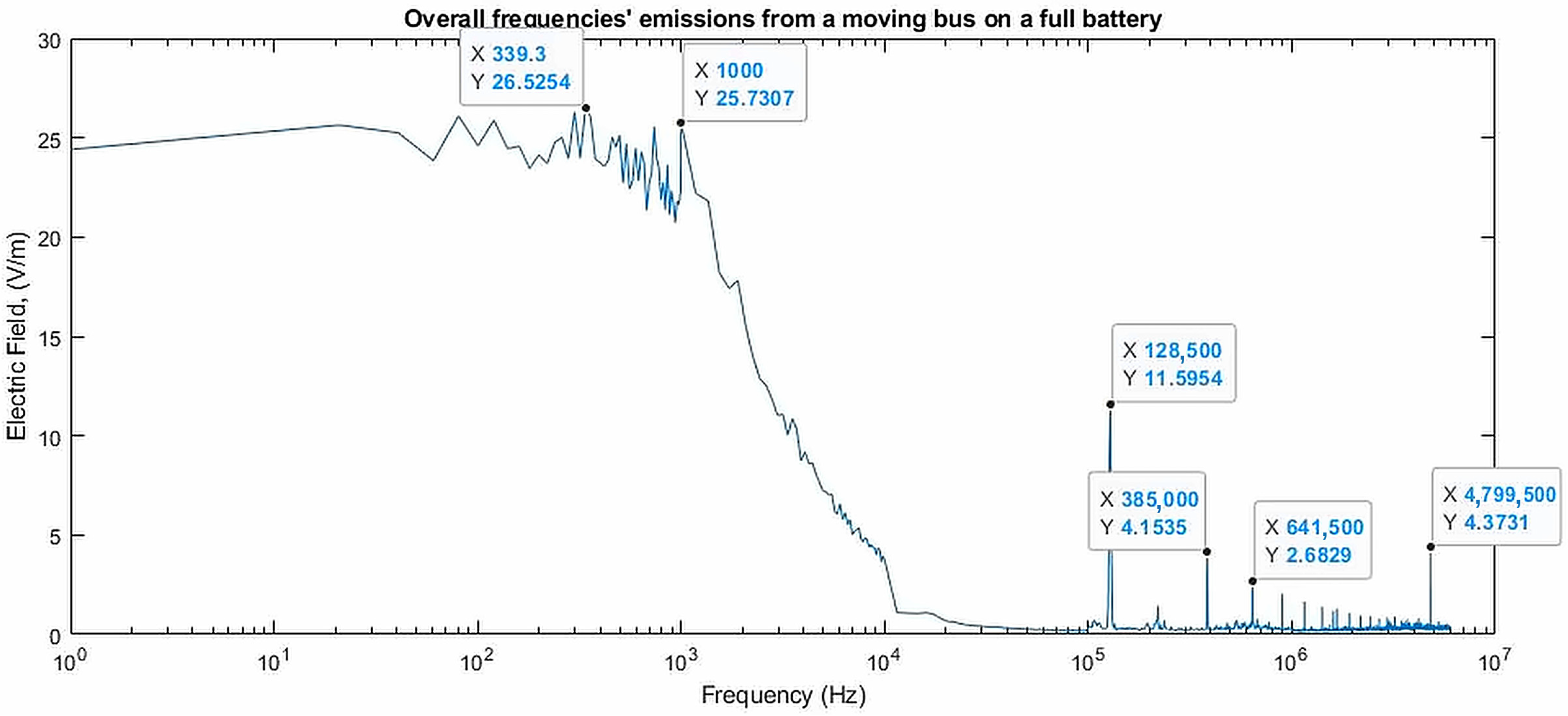
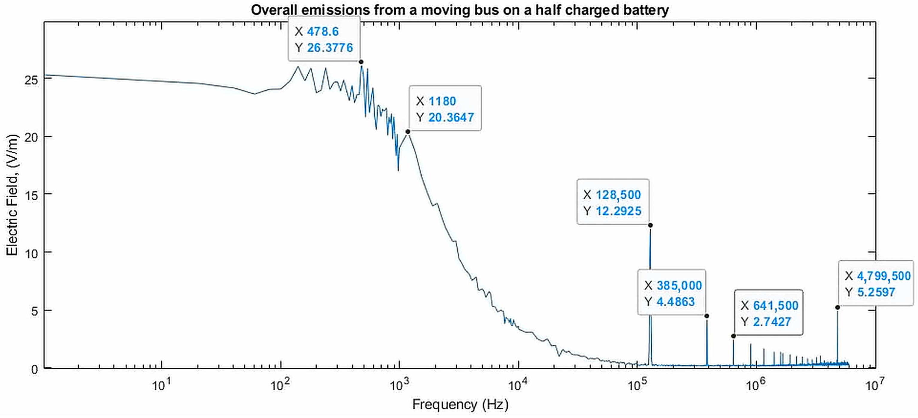
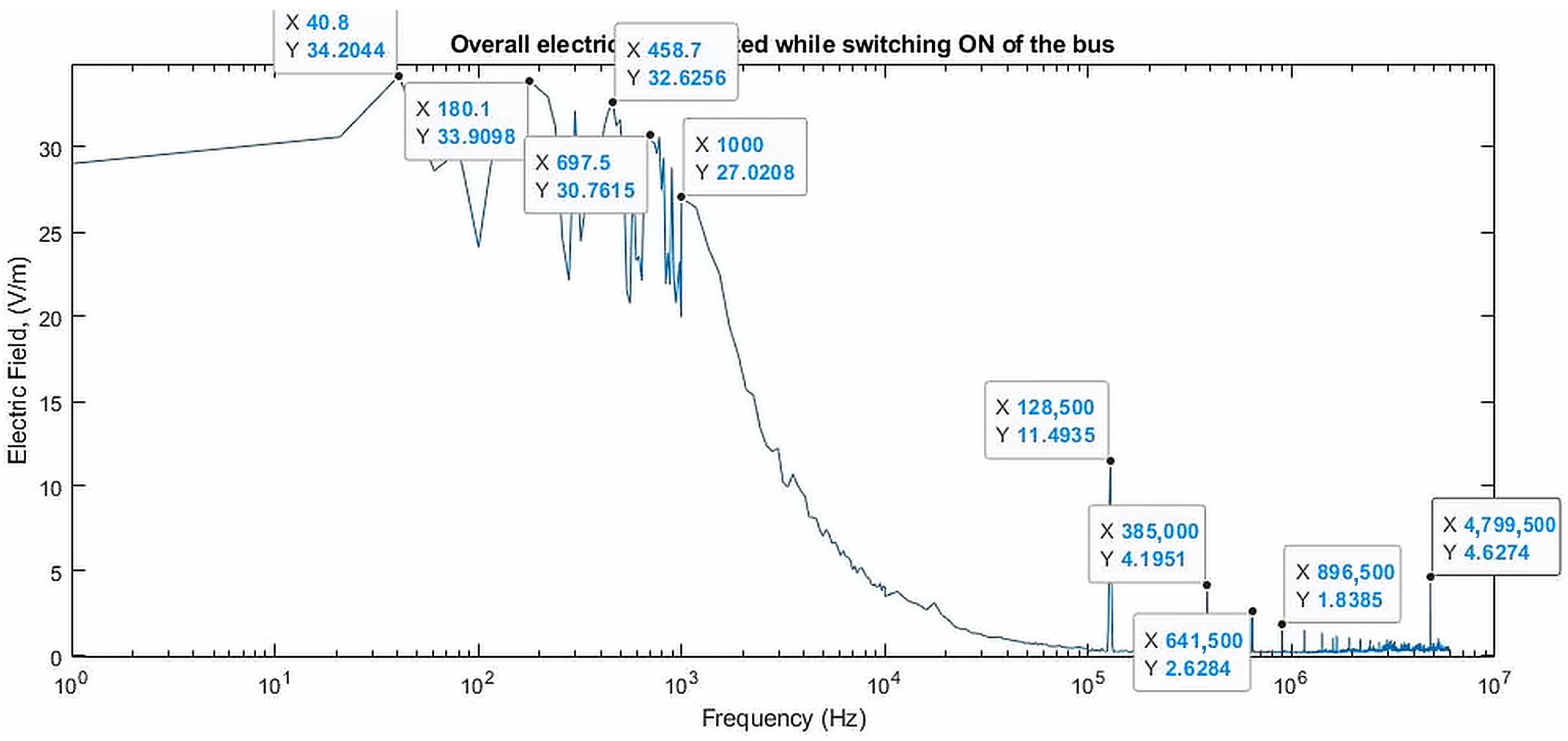
All four reproduced spectra (Figure 5, Figure 6, Figure 7 and Figure 8) share a flat plateau from the lowest displayed frequency (1 Hz) to about 100 Hz, at nearly the same level in each recording (approximately 25, 25, 23–25 and 29–34 V/m), followed by a fluctuating region up to about 1–2 kHz and a smooth roll-off to below 1 V/m by about 10 kHz. Three observations indicate that this region is dominated by the measurement chain rather than by emission from the bus. First, the plateau is flat and featureless where physical sources in the bus—the motor fundamental while driving, or mains-frequency harmonics during charging—would be expected to appear as discrete lines. Second, the roll-off resembles the transfer function of a low-pass response rather than an emission envelope. Third, in the supplementary recordings of Section 5.1.5, the lowest frequency bin read between about 4 and 16 V/m in every recording, including 9.3 V/m with the bus de-energized (Table S1)—the same order as the plateau—whereas the charging emissions appeared as discrete lines of about 1 V/m. A hand-held electric-field probe in the quasi-static regime is, moreover, perturbed by the operator’s body and by probe motion, whereas exposure assessment requires the unperturbed field [164]. Because the instrument settings of the five main acquisitions were not logged and their raw recordings were not retained, the specific mechanism—a filter or display setting, the low-frequency response of the electric-field sensor, or handling artefacts—could not be identified retrospectively. The region below about 1 kHz is therefore treated as instrument-limited: the maxima within it are reported in Table 8 only as recorded values, and no physical interpretation is attached to the frequencies at which they occur. These maxima differ from neighbouring values by only a few percent (26.5 V/m at 339.3 Hz versus 25.7 V/m at 1 kHz in Figure 5; 34.2 V/m at 40.8 Hz versus 33.9 V/m at 180.1 Hz in Figure 8), so the frequency of the maximum is not a characteristic of the vehicle.
5.1.2. Moving Bus Conditions
For the moving bus at full battery (Figure 5), the spectrum above the instrument-limited region falls to below 1 V/m by about 10 kHz and contains discrete lines at 128.5 kHz (11.6 V/m), 385 kHz (4.2 V/m), 641.5 kHz (2.7 V/m) and 4.80 MHz (4.4 V/m). The maximum within the instrument-limited region, 26.5 V/m at 339.3 Hz, is not interpreted (Section 5.1.1).
Figure 5.
Electric field spectrum of the moving electric bus with full battery (100% SoC). Below about 1 kHz the spectrum is instrument-limited (Section 5.1.1); the maximum in this region (26.5 V/m at 339.3 Hz) is not attributed to the vehicle. The discrete lines above 100 kHz recur in all operating conditions (Table 8).
For the half-battery condition (approximately 50% SoC, Figure 6), the same lines appear at closely similar levels (12.3, 4.5, 2.7 and 5.3 V/m), and they recur in the switching-on and charging spectra (Table 8). The 128 kHz line is also present, at 11.2 V/m, in the supplementary recording made with the bus de-energized (Section 5.1.5). Lines that recur at the same frequencies and levels whether the bus is driving, charging or switching on cannot be attributed to a particular operating state, and without a reference spectrum for these conditions their origin—vehicle, site or instrument—cannot be established. They are therefore not attributed to power-electronic switching in the vehicle, and the difference between the maxima at 339.3 Hz and 478.6 Hz, which lies within the instrument-limited region, is not interpreted.
Figure 6.
Electric field spectrum of the moving electric bus with half battery (≈50% SoC). Below about 1 kHz the spectrum is instrument-limited (Section 5.1.1); the maximum in this region is 26.4 V/m at 478.6 Hz.
5.1.3. Charging Conditions
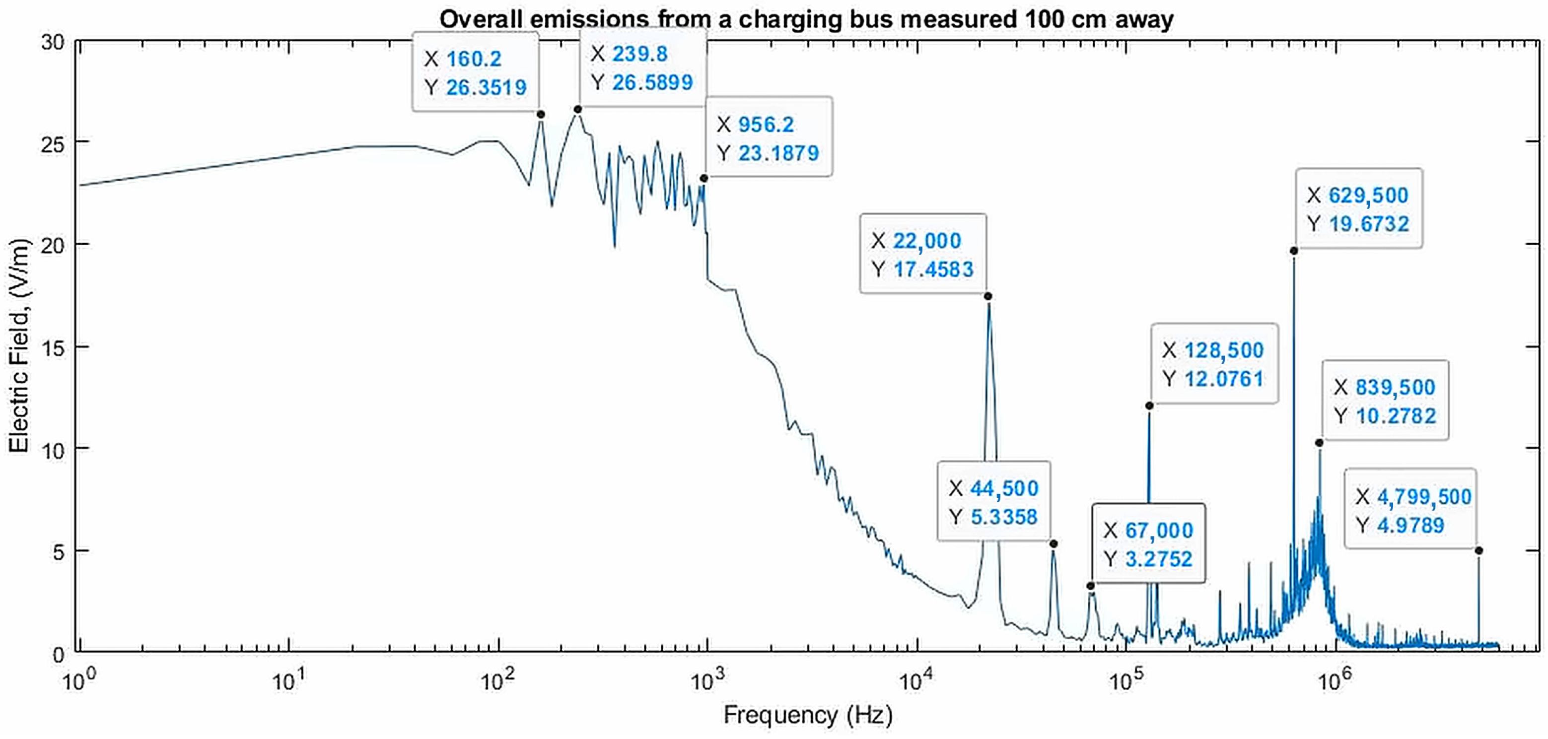
During charging, the maximum recorded at 20 cm from the charging port was 36.4 V/m at 1.0 Hz, and at 100 cm it was 26.6 V/m at 239.8 Hz (Figure 7). Both lie in the instrument-limited region; the value at 1.0 Hz, moreover, lies at the lower band edge of the instrument, where offset and motion artefacts are strongest. Neither is interpreted as an emission of the charging process.
If the two maxima were taken at face value, the 27% difference over a fivefold change in distance would correspond to a field decaying approximately as r−0.2, since (1/5)0.2 ≈ 0.72, far more slowly than the 1/r decay of a long conductor. Because both values lie in the instrument-limited region and come from single acquisitions, this comparison carries no inferential weight and is not used as a finding. Above 10 kHz, however, the charging spectrum (recorded at 20 cm; Table 8) contains lines that are absent, or far weaker, in the other operating conditions: a family at 22.0, 44.5 and 67.0 kHz (17.5, 5.3 and 3.3 V/m) and lines at 629.5 and 839.5 kHz (19.7 and 10.3 V/m). These are the only condition-specific features of the main campaign. The 22 kHz family coincides in frequency with the harmonic family recorded by the magnetic sensor during charging in the supplementary sessions (Section 5.1.5), which supports its attribution to the charging system; charging-related emissions in this band have also been reported for EV charging processes and on-board chargers [106,165,166].
Figure 7.
Electric field spectrum during charging at 100 cm from the charging port (above 10 kHz, recorded at 20 cm; Table 8). Below about 1 kHz the spectrum is instrument-limited (Section 5.1.1). The line family at 22.0, 44.5 and 67.0 kHz and the lines at 629.5 and 839.5 kHz are specific to the charging condition (Section 5.1.3).
5.1.4. Switching-On Condition
For the switching-on condition (Figure 8), the maximum of 34.2 V/m at 40.8 Hz lies on the plateau of the instrument-limited region and exceeds the next marked value (33.9 V/m at 180.1 Hz) by less than 1%. It is therefore not interpreted as a transient emission, and no conclusion is drawn from its difference from the driving conditions: a difference of this size between single acquisitions cannot be separated from run-to-run variability, and the plateau level may itself be set by the measurement chain. Above 1 kHz the switching-on spectrum shows the same lines at 128.5 kHz, 385 kHz, 641.5 kHz and 4.80 MHz as the moving-bus spectra (Table 8). Characterizing the transient of contactor closure and inverter initialization would require a triggered time-domain capture, which this campaign did not include.
Figure 8.
Electric field spectrum during the switching-on condition. Below about 1 kHz the spectrum is instrument-limited (Section 5.1.1); the maximum in this region (34.2 V/m at 40.8 Hz) is not attributed to the vehicle.
5.1.5. Supplementary Charging Measurements
Figure 9 shows the mean spectra of representative recordings from the supplementary sessions, and Table S1 lists the line levels of every recording. In measurement campaign 2, with the bus de-energized, the electric-field spectrum above a few kilohertz was below 0.3 V/m except for the 128 kHz line (11.2 V/m). During charging with each of the three chargers, a line pair appeared at about 57.5 kHz and at its second harmonic, about 115.5 kHz. At 57.5 kHz the level was 1.17–1.24 V/m in the six recordings (three chargers, each with the probe near the charging port and at 1 m), against 0.21 ± 0.03 V/m in the reference, a rise of about six times; at 115.5 kHz the corresponding values were 1.09–1.18 V/m against 0.15 ± 0.02 V/m, a rise of about seven to eight times. The standard deviation across sweeps within a recording was about 0.2 V/m, the run means agreed to within ±3%, and the near and 1 m positions did not differ measurably (1.21 and 1.20 V/m at 57.5 kHz, averaged over the three chargers). The pair was absent from the three earlier recordings labelled “charging” (0.20–0.22 V/m) and from the charging recordings of measurement campaign 3, so the ±3% reproducibility refers to the six recordings with chargers 1–3. The broadband floor between about 10 and 100 kHz was slightly higher in the reference recording than during charging (about 0.1 against 0.05 V/m), so the comparison is made for the discrete lines only. The equal level near the port and at 1 m suggests a distributed source, such as common-mode current on the charging cable or chassis, although coupling through the site earthing or pickup in the measurement chain cannot be excluded; because the three chargers were identical DC units and the de-energized reference does not separate “vehicle off” from “no charging”, the source cannot be placed on the charger or the vehicle side.
Figure 9.
Supplementary charging measurements on the same bus (1–150 kHz; mean of all sweeps in each recording; n = number of sweeps). (a) Electric field in measurement campaign 2 with the bus de-energized and during charging with charger 1, with the probe near the charging port and at 1 m. (b) Magnetic flux density in measurement campaign 3 with the bus de-energized, during steady-state charging and at the position labelled “short distance”. The lowest bins (below about 5 kHz) are affected by low-frequency leakage, and the 128 kHz electric-field line is present with the bus de-energized.
In measurement campaign 3, with the bus de-energized, the magnetic flux density near 22 kHz was 0.24 ± 0.11 nT (96 sweeps) and 0.18 ± 0.06 nT (33 sweeps). During steady-state charging it was 0.48 ± 0.17 nT, within the scatter of the reference, and at the position labelled “short distance” to 1.44 ± 0.71 nT, accompanied by a second harmonic near 44.5 kHz (0.35 ± 0.09 nT against 0.11–0.14 nT before charging); at the positions labelled “near the bus” and “20 cm” it was 0.35 ± 0.16 and 0.41 ± 0.17 nT, and a first recording labelled “charging 1” (0.16 ± 0.05 nT) showed no rise. The 22 kHz family corresponds in frequency to the family seen in the electric-field spectrum during charging in the main campaign (Figure 7). In the electric-field set recorded in the same session, labelled “2 charger”, a 22.5 kHz component of 2.7 ± 1.2 V/m was already present before charging and did not increase during charging (2.4 ± 1.3 V/m near the port; 4.9 ± 3.0 V/m at 1 m), which indicates a contribution from the charging equipment on site rather than from the vehicle. Charger-specific supraharmonic emission concentrated in narrow bands, including 56–60 kHz, has likewise been reported in conducted measurements on EV chargers [111]. These data cover the charging condition and the 1–150 kHz band only.
5.1.6. Summary of Findings and Comparison with Exposure Guidelines
Taken together, the case study supports three findings, each qualified by the limitations in Section 5.2. First, below about 1 kHz the hand-held electric-field measurements are instrument-limited, so the case study provides no evidence on the low-frequency emission of the bus. Second, the emissions that can be attributed to an operating state are charging-related lines in the supraharmonic band discussed in Section 4.4—an electric-field line pair at 57.5 and 115.5 kHz, which rose about six- to eightfold above a de-energized reference and was reproducible to within ±3% across six runs, and a family near 22 kHz, whose magnetic-field rise was clear at one probe position only; the 22 kHz family and the lines at 629.5 and 839.5 kHz are also the only condition-specific features of the main campaign. Third, discrete lines that recur at the same frequencies in every operating state, including with the bus de-energized, show why a reference spectrum is indispensable for the near-field characterization of a vehicle in service.
A comparison against the exposure guidelines is made above 1 kHz only, since the reported quantity is an electric field strength and the ICNIRP 2010 general-public reference levels [25] are defined in the same units. Below 1 kHz the instrument-limited maxima are neither estimates nor bounds of the vehicle contribution. Two qualifications apply. First, the summation below is an estimate from the resolved lines, not a weighted-peak assessment, so it establishes a margin rather than formal compliance [167]. Second, reference levels are conservative surrogates for the basic restrictions on induced in-body fields; conformity with the former implies conformity with the latter, but the converse does not hold. The condition-specific charging lines above 1 kHz are also below the reference level of 83 V/m that applies from 3 kHz to 10 MHz: the largest, 19.7 V/m at 629.5 kHz and 17.5 V/m at 22.0 kHz, correspond to about 24% and 21% of it, and the supplementary data give about 1.5% for the electric field at 57.5 kHz (1.24 V/m) and about 0.005% for the magnetic flux density at 22 kHz (1.44 nT against 27 µT) [25]. Summed over all resolved lines above 1 kHz, as ICNIRP 2010 requires for multi-frequency fields [25], the exposure ratios are 0.28–0.30 for the driving and switching-on conditions, 0.88 for charging and at most 0.22 for the supplementary data; for the lines above 100 kHz, the ICNIRP 2020 reference levels [168] give a sum of squared ratios below 0.01.
Table 8.
Summary of the near-field electric-field measurements on an electric bus under five operating conditions (1 Hz–10 MHz; one acquisition per condition; author’s measurements).
5.2. Limitations of the Case Study
Six limitations bound the interpretation of these results and are stated explicitly so that the scope of the claims is unambiguous. First, the campaign characterises a single vehicle. The measurements establish the emission signature of one 130 kW heavy-duty platform and are not presented as representative of the class; inter-vehicle variability in powertrain topology, cable routing and shielding practice is known to be substantial, and the quantitative values here should not be generalised without replication across platforms. Second, each of the five main conditions was characterized from a single acquisition, so the reported values are point estimates carrying no repeatability interval; repeated recordings exist only for the charging condition, from the supplementary sessions, and only between 1 and 150 kHz. Third, no ambient or de-energized reference spectrum was recorded for the five main conditions, so lines common to all of them cannot be assigned to the vehicle, the site or the instrument; such a reference exists only for the supplementary charging data.
Fourth, magnetic-field data are available only for the charging condition and only between 1 and 150 kHz; no magnetic-field data exist for the driving and switching-on conditions or below 1 kHz, where the magnetic field is the quantity of primary concern for exposure assessment. A combined electric- and magnetic-field campaign covering all operating states is therefore the most immediate extension of this work. Fifth, the analyzer was hand-held, its settings for the main acquisitions were not logged, and the electric-field sensor is not isotropic, so the values are single-orientation readings and the region below about 1 kHz is instrument-limited (Section 5.1.1). Sixth, and most consequential for how these numbers should be read, the measurements are near-field acquisitions. At the frequencies analysed here the free-space wavelength exceeds the vehicle dimension (it is about 60 m even at 5 MHz), and with the probe within a metre of the sources, so the probe samples a quasi-static field region rather than a propagating wave. The term radiated is used throughout this article in the general sense of field emission into the surrounding space, not in the CISPR far-field sense. The values are consequently not comparable with CISPR 25 or CISPR 12 limits, which are defined for antenna measurements at fixed distances above 30 MHz, and no such comparison is attempted. Spectrum plots are reproduced for four of the five conditions; the 20 cm charging condition is summarized numerically in Table 8.
6. Shielding and Mitigation Strategies
Mitigating EMF exposure and EMI requires robust shielding strategies. The literature extensively compares passive materials (aluminum, ferrite, nanocrystalline) with emerging active cancellation techniques and design optimization approaches [17,51,95,149,150,169,170,171,172,173,174,175].
6.1. Passive Shielding Materials
Passive shielding relies on the intrinsic electromagnetic properties of materials to attenuate EMF. Ferrite materials have high magnetic permeability, allowing them to redirect magnetic flux through a low-reluctance path and confine the field. The high electrical conductivity of aluminum and copper sheets generate eddy currents that oppose the incident magnetic field, providing attenuation through field cancellation [172,176]. A summary of passive shielding materials for EV WPT systems is provided in Table S5 of the Supplementary Materials.
Talluri et al. [172] used finite-element analysis to quantify the ohmic losses introduced by different plate-shield and ferrite-bar configurations, and showed that an optimized configuration restores the mutual inductance to levels comparable with the unshielded case, with aluminium proposed for the vehicle-side shield and iron for the ground side. For light-duty systems, Zhang et al. [176] note that aluminium plates are typical at lower power levels and ferrite plates, with an efficiency reduction below 1%, at higher levels; they show that a ferrite “teeth” shield with a back-ferrite extension reduced the simulated stray field of a 200 kW system from 41.0 to 23.8 µT at 0.8 m, and a reduction of about 27% was confirmed in a 3.3 kW scaled-down test. Duan et al. [88] show that composite cores with intermediate insert blocks can reduce magnetic-field leakage by 91.6% while improving transfer efficiency by 34% relative to a core-less design.
6.2. Active Shielding Technologies
Active shielding uses additional coils carrying controlled currents to generate a cancellation field that opposes the leakage magnetic field from the WPT system [177,178,179]. Lee et al. [178] added active cancel coils to the pick-up of an on-line electric vehicle and reduced the field at 1 m to about one fifth of its uncancelled value, below 50 mG (5 µT) at maximum power. Choi et al. [179] generalized the method to cancel coils on both the primary and secondary coils and, combined with further measures such as passive aluminium plates, kept the field at 1 m below 44 mG (4.4 µT) at 12 kW. Furthermore, active shielding has been specifically adapted to protect medical implants, such as pacemakers, from WPT-induced EMI [17]. A comparative summary of passive, active and hybrid shielding is provided in Table S6 of the Supplementary Materials.
6.3. EMI Mitigation in Traction Drives
Mitigation strategies for high-frequency EMI from traction inverters, which differ significantly from low-frequency WPT shielding [29,32,60,96,180,181], are summarized in Table 9. Converter switching noise reduction techniques for enhancing EMC performance in HEV and EV [29] have yielded several practical solutions for reducing the switching noise of the Low-Voltage DC-DC Converter (LDC), including noise path improvements and noise source reduction techniques. EMI measurement and reduction for SiC MOSFET-based motor drivers [60] presents a comprehensive low-cost EMI reduction scheme for 800 V SiC-based motor drivers, achieving CISPR 25 Class 3 compliance. Troscher and Haschberger [180] showed that careful optimization of the grounding and current return path topology has the potential to reduce both conducted and radiated emissions without adding any additional components, representing a zero-cost mitigation strategy.
Table 9.
Quantified EMI Mitigation Techniques for EV Traction Drives and DC-DC Converters.
Two cautions apply when comparing the entries in Table 9. First, attenuation is band-specific: a figure quoted at 1 MHz carries no implication for behaviour at 100 MHz. Second, the reported figures for modulation-based techniques are not directly comparable between studies, because peak and quasi-peak detector readings respond differently to spread-spectrum energy redistribution and the resolution bandwidths used differ across the literature. The broader pattern is nonetheless consistent: source-side measures—modulation strategy, layout and return-path topology—deliver attenuation at near-zero volume and cost but saturate quickly, whereas path-side passive filtering delivers far greater attenuation at a volume and mass penalty that dominates converter packaging. Hybrid active-passive filtering occupies the middle ground and is a candidate for the power densities projected for next-generation traction drives [102].
6.4. Harness Shielding and Transfer Impedance
Section 3.3 and Section 4 identified the high-voltage harness, excited by common-mode current, as the dominant radiating structure above roughly 30 MHz. It follows that the governing figure of merit for harness shielding is not shielding effectiveness—a quantity defined for a plane wave incident on a barrier, as in Equation (10)—but the transfer impedance, which relates the voltage developed on the inner conductor to the current flowing on the shield. Wu et al. [103] develop this explicitly for the braid-plus-foil double shields used on EV high-voltage connection cables, deriving a transfer-impedance model that accounts separately for shield DC resistance and braid aperture (“keyhole”) inductance, and validating it by triaxial measurement on three cable constructions with errors below 20% across the measured bands. The practical consequence is that harness performance is set by braid optical coverage, weave angle and, decisively, by the quality of the 360-degree shield bond at each connector, rather than by the cable specification in isolation. This also explains why converter enclosure shielding yields diminishing returns once bond quality becomes the limiting term.
Prediction studies support the same conclusion from the opposite direction. Jia et al. [186] reproduce CISPR 25 radiated emissions over 30–1000 MHz to within 7 dB using measured common-mode current distributions on the cable bundle alone, and Schneider et al. [187] reach comparable agreement for a complete electric drive system using bench-measured disturbance currents combined with transfer functions. Both results indicate that the harness, rather than the converter housing, determines vehicle-level radiated emission. For heavy-duty platforms, where cable runs between the battery pack and the traction inverter are several metres longer than in passenger vehicles—as in the bus characterized in Section 5—shield termination discipline is correspondingly more consequential, and the degradation of shielding performance below 100 kHz noted in Table 3 becomes a design constraint rather than a footnote.
6.5. Design Optimization
Beyond physical shielding, optimizing the design of the EV’s electrical architecture is crucial for EMC [80,132,180]. This includes utilizing DD or DDQ topologies for WPT to reduce far-field leakage, allowing for the minimization of the length (L) of high-voltage cables and optimization of their routing to reduce their effectiveness as unintentional antennas, which directly addresses the radiated emission mechanisms described in Section 3.3. Further measures are to locate the inverter, BMS, and OBC to maximize the distance from passenger compartments and sensitive ECUs, and to implement spread-spectrum PWM techniques in the traction inverter to distribute the switching noise energy over a wider frequency band, reducing the peak amplitude at any single frequency.
7. Standards, Safety Compliance, and Measurement Infrastructure
Ensuring EV compliance requires rigorous testing against international standards. The literature heavily references ICNIRP guidelines for human safety and CISPR standards for vehicle/component emissions. The evolving regulatory landscape presents significant differences in requirements across different countries (EU, USA, Japan, China), complicating global vehicle certification [10,25,28,39,141,188,189,190,191].
7.1. Key Standards Framework
The transition from reference levels (magnetic flux density) to basic restrictions (induced electric field in tissue) in ICNIRP 2010 has significant implications for WPT compliance assessment [25,188,192]. The review of safety and exposure limits of electromagnetic fields in wireless electric vehicle charging applications [188] provides a detailed comparison of the ICNIRP 1998, ICNIRP 2010, and IEEE C95.1-2019 [193] exposure frameworks. Safety considerations for EV charging in India [191] extends this analysis to emerging markets, highlighting the need for harmonized global standards. The project metrology for inductive charging of electric vehicles [40] addresses the measurement traceability challenge for WPT EMF assessment. Above 100 kHz, the ICNIRP 2020 guidelines [168] govern heating effects, while the ICNIRP 2010 restrictions on nerve stimulation continue to apply up to 10 MHz; static magnetic fields, such as those of DC battery and charging cables, fall under the ICNIRP 2009 guidelines [75] (Section 3.4).
While ICNIRP defines exposure limits and CISPR defines emission limits, neither is directly enforceable on a vehicle manufacturer. The instrument that makes selected parts of both mandatory is UN Regulation No. 10, administered by the World Forum for Harmonization of Vehicle Regulations (WP.29), which governs electromagnetic compatibility type approval for road vehicles and for their electrical and electronic sub-assemblies. The regulation references CISPR and ISO test methods rather than defining its own, so its successive amendment series serve as a useful marker of which laboratory methods have achieved regulatory consensus. The 06 series, adopted by WP.29 in March 2019, aligned vehicle narrowband emission limits and the coupled charging-mode test set-ups with CISPR 12 [194]. The 07 series, approved by the Working Party on Lighting and Light-Signalling in 2024, is the more consequential for the themes of this review: it extends the radiated immunity test frequency range to 6 GHz to encompass LTE, 5G NR and Wi-Fi bands, and, for the first time in an automotive EMC regulation, introduces explicit operating conditions and failure criteria for automated driving systems, emergency call (eCall) systems, and acoustic vehicle alerting systems (AVAS) [24]. Table 10 shows key international standards for EV EMC and EMF safety, illustrating the issuing body, the scope & applications, key limits, and frequency range for every standard.
Table 10.
Key International Standards for EV EMC and EMF Safety.
This represents a conceptual shift rather than an incremental one. Emission and immunity limits have historically been framed as protections for radio reception, with functional degradation of the vehicle treated as a secondary concern. The 07 series treats an EMC-induced malfunction of an automated driving function as a type-approval failure in its own right. In doing so it creates a requirement—function-referenced immunity assessment—for which neither CISPR 25 nor ISO 11452 currently provides a measurement methodology, since both remain limit-line instruments that record field strength against a threshold rather than system behaviour against a functional criterion. Closing this methodological gap is among the most consequential outstanding tasks in automotive EMC standardization, and it bears directly on the V2X and autonomous-driving concerns raised in Section 1.
A related point of currency concerns CISPR 25 itself. Edition 5.0, published on 16 December 2021, extends the radiated emission measurement range to 5925 MHz from 2.5 GHz in the preceding edition, adds frequency bands corresponding to newer on-board radio services, introduces normative annexes on measurement uncertainty, and deletes the TEM-cell annex that earlier editions had offered as a pre-compliance route; the deletion is listed among the significant technical changes in the foreword of the standard [28]. Test plans and review articles that continue to present the TEM cell as a CISPR-aligned pre-compliance method therefore require revision.
The heavy-duty asymmetry identified in this review extends to charging infrastructure standardization. Light-duty inductive charging is addressed by IEC 61980, ISO 19363 and SAE J2954, and the EMC of conductive charging by IEC 61851-21-1 for on-board chargers and IEC 61851-21-2 for off-board charging systems [200,201]; all appear in Table 10. Heavy-duty wireless charging is addressed only by SAE J2954/2, which remains an Information Report [196], and the in-vehicle magnetic-field measurement procedure of IEC 62764-1 is limited to vehicle categories M1 and N1 [199], so buses and trucks have no standardized procedure for assessing occupant exposure. The corresponding heavy-duty instrument for conductive charging is the Megawatt Charging System (MCS), developed by CharIN and standardized as SAE J3271, with a recommended operating envelope reaching 1250 V DC and 3000 A, approximately 3.75 MW [203]. The infrastructure cost and projected demand of megawatt charging across Europe have been quantified separately [208]. The step from a few hundred kilowatts to the megawatt class is not merely quantitative in electromagnetic terms. An approximately six-fold increase in charging current raises both the conducted disturbance injected at the grid interface and the quasi-static field in the immediate vicinity of the coupler and cable—the regime in which the case study of Section 5 found its only condition-specific emission lines, during charging.
One design feature of MCS is particularly instructive. Whereas the Combined Charging System (CCS) carries high-level communication as single-ended power-line communication, MCS uses single-pair Ethernet (10BASE-T1S), specified in ISO 15118-10:2025 [204], over dedicated, balanced twisted-pair conductors [203]. As a technical observation, a dedicated balanced channel is less exposed to common-mode coupling from the power conductors than a signal superimposed on them. The choice illustrates a coupling the EMC literature has treated only sparsely: the interaction between the emissions of a power converter and the integrity of the communication channel that controls that same converter. For electric buses and trucks—the platform class for which this review identifies a standardization gap—this is likely to become a defining EMC problem of the next standards cycle, and no dedicated assessment methodology for it yet exists.
7.2. Global EMC Testing Infrastructure
The global infrastructure for EV EMC testing (Figure 10) has expanded significantly to accommodate the unique challenges posed by high-voltage electric powertrains. Testing facilities must handle high-power dynamometers inside shielded chambers, high-voltage LISNs, and specialized WPT test setups [48,100,209,210]. A recent comparative review of EMI emission and immunity measurement practice across LISN, near-field probe, TEM/GTEM, anechoic and reverberation-chamber methods provides a current account of the diagnostic options available at each stage of this infrastructure [211].
Figure 10.
EMC Measurement Methodologies for EVs.
8. Key Challenges and Research Opportunities
The preceding sections show that the field has moved beyond the classification of emissions as conducted or radiated, but that its most consequential problems lie at the interfaces between disciplines and between standards. Six challenges stand out; Table 11 summarizes each of them together with the research opportunity it opens.
Table 11.
Key challenges and research opportunities in EV EMC.
First, the shift to wide-bandgap devices couples emission to reliability. The edge rate that sets the emission spectrum (Section 3.1) also drives bearing currents and partial discharge [63,64], yet no CISPR or ISO limit addresses this trade-off, and gate drives are still optimized against emission or switching loss alone [32]. Second, immunity is becoming function-referenced: the UN R10 07 series treats an EMC-induced malfunction of an automated driving function as a type-approval failure [24], but CISPR 25 and ISO 11452 provide no method to assess it (Section 7.1). Third, heavy-duty vehicles fall into a standards gap: megawatt charging reaches 3000 A [203], heavy-duty wireless charging is at the Information-Report stage [196], and buses and trucks have no standardized in-vehicle magnetic-field procedure, because IEC 62764-1 covers categories M1 and N1 only [199].
Fourth, supraharmonic emission from chargers lacks harmonized limits, and the available measurement methods are not directly comparable (Section 4.4) [111,118,123]. Fifth, vehicle-level radiated emission is governed by shield termination rather than by cable specification (Section 6.4) [103,186,187], yet termination quality is rarely verified in situ. Sixth, laboratory test conditions do not reproduce dynamic operation [100,212], and, as the case study of Section 5 illustrates, in-service near-field measurements without reference spectra, repeated acquisitions and documented instrument settings cannot separate vehicle emissions from site and instrument contributions [48]. Two cross-cutting opportunities apply to several of these challenges: AI/ML surrogate models trained on full-wave and measured data could make the corresponding assessments tractable at the design stage [151], and hybrid active–passive mitigation adaptable to dynamic operating conditions remains the most promising route for heavy-duty wireless charging [150,170].
9. Conclusions
The electromagnetic environment of electric vehicles is highly complex, owing to its wide spectrum of emissions ranging from quasi-static magnetic fields of traction currents to multi-gigahertz radiated noise from power semiconductor switching. This comprehensive review and exploratory case study demonstrate that while significant advancements have been made in predictive modeling and active shielding technologies, substantial challenges remain.
The narrative review of 260 publications reveals a marked increase in EV EMC research output over the past three decades, with 47% of the works cited in this article published since 2021 (Figure S1). The dominant research themes are Wireless Power Transfer (WPT) and human exposure safety, followed by shielding and EMF mitigation, and traction drive power electronics. The transition to wide-bandgap semiconductors (SiC and GaN) and high-power wireless charging necessitates continuous evolution of EMC mitigation strategies and international testing standards.
The supraharmonic frequency band (2–150 kHz) represents a critical regulatory gap that must be addressed as EV penetration increases. Although compatibility levels and measurement methods now exist for parts of this band, no harmonized emission limits below 150 kHz yet exist for EV charging equipment, despite the current distortion injected into the grid by charger power-factor-correction stages. The regulatory picture is also moving faster than the review literature reflects: the UN R10 07 series extends vehicle immunity testing to 6 GHz and introduces failure criteria for automated driving functions, while the Megawatt Charging System pushes heavy-duty conductive charging toward 3000 A—a regime for which existing test infrastructure and limit lines were not designed.
The exploratory case study on a single heavy-duty electric bus showed that the attributable emissions were charging-related lines in the supraharmonic band—an electric-field line pair at 57.5 and 115.5 kHz, which rose about six- to eightfold above a de-energized reference and was reproducible to within ±3% across six runs, and a family near 22 kHz, whose magnetic-field rise was clear at one probe position only. The estimated exposure ratios were below the ICNIRP general-public reference levels. Below about 1 kHz the hand-held electric-field spectra were instrument-limited, so the case study provides no evidence on the low-frequency emission of the bus, and lines common to all operating states could not be assigned to the vehicle. These results underline the measurement requirements set out in Section 8: de-energized references, repeated acquisitions, documented instrument settings and combined electric- and magnetic-field data.
Future research must focus on system-level, multi-physics optimization that simultaneously considers electromagnetic performance, thermal management, efficiency, and human safety. The specific research opportunities are set out in Section 8 and Table 11; the most pressing are harmonized supraharmonic emission limits and measurement methods for EV chargers, function-referenced immunity assessment for automated-driving functions, and EMC and exposure assessment methods for megawatt-class conductive charging and other heavy-duty platforms, where multi-kiloampere DC currents and communication-channel robustness fall outside the scope of current vehicle and EVSE test standards.
Supplementary Materials
The following supporting information can be downloaded at: https://www.mdpi.com/article/10.3390/vehicles8110298/s1. Figure S1: Publication years of the 212 dated works cited in the article (2026: partial year); Table S1: Supplementary charging recordings on the electric bus (1–150 kHz); Table S2: WPT coil topologies and EMF performance; Table S3: AI and machine learning algorithms used for EV EMC; Table S4: Modelling and simulation techniques used for EV EMC analysis; Table S5: Passive shielding materials for EV WPT systems; Table S6: Active versus passive shielding in WPT systems. References [17,34,56,58,65,78,88,101,131,142,144,151,153,154,155,156,161,162,170,172,176,177,178,179] are cited in the Supplementary Materials.
Funding
This research received no external funding.
Data Availability Statement
The exported spectra of the five main operating conditions and the raw MCS recordings of the supplementary charging sessions (summarized in Table S1) are available from the author on reasonable request.
Acknowledgments
The author discloses very limited use of AI tools during the preparation of this manuscript, strictly for language polishing, formatting and aligning figures and tables, cross-checking the consistency of in-text citation numbering, and assisting with literature screening, deduplication, and data extraction. No AI-generated text was directly inserted into the manuscript, nor was AI used to generate or alter experimental data or core analyses. All literature claims and references were rigorously and independently drafted and verified against primary sources by the author, who takes full responsibility for the final content of this publication.
Conflicts of Interest
The author declares no conflicts of interest.
Abbreviations
The following abbreviations are used in this manuscript:
| ABS | Anti-lock Braking System |
| ADAS | Advanced Driver-Assistance System |
| AI | Artificial Intelligence |
| AIMD | Active Implantable Medical Device |
| ALSE | Absorber-Lined Shielded Enclosure |
| AMN | Artificial Mains Network |
| BCI | Bulk Current Injection |
| BEV | Battery Electric Vehicle |
| BMS | Battery Management System |
| CCS | Combined Charging System |
| CISPR | International Special Committee on Radio Interference |
| CM | Common Mode |
| CNN | Convolutional Neural Network |
| CNS | Central Nervous System |
| DD | Double-D (coil topology) |
| DDQ | Double-D Quadrature (coil topology) |
| DM | Differential Mode |
| DNN | Deep Neural Network |
| DUT | Device Under Test |
| DWPT | Dynamic Wireless Power Transfer |
| ECU | Electronic Control Unit |
| EMC | Electromagnetic Compatibility |
| EMF | Electromagnetic Field |
| EMI | Electromagnetic Interference |
| EPS | Electric Power Steering |
| EV | Electric Vehicle |
| FDTD | Finite-Difference Time-Domain |
| FEM | Finite Element Method |
| FFT | Fast Fourier Transform |
| FOD | Foreign Object Detection |
| GA | Genetic Algorithm |
| GaN | Gallium Nitride |
| GP | General Public (ICNIRP reference-level category) |
| HEV | Hybrid Electric Vehicle |
| HFSS | High-Frequency Structure Simulator |
| ICNIRP | International Commission on Non-Ionizing Radiation Protection |
| IEC | International Electrotechnical Commission |
| IGBT | Insulated-Gate Bipolar Transistor |
| ISO | International Organization for Standardization |
| LDC | Low-Voltage DC-DC Converter |
| LISN | Line Impedance Stabilization Network |
| LOD | Living Object Detection |
| MCS | Megawatt Charging System |
| ML | Machine Learning |
| MoM | Method of Moments |
| MOSFET | Metal-Oxide-Semiconductor Field-Effect Transistor |
| NVH | Noise, Vibration, and Harshness |
| OATS | Open-Area Test Site |
| OBC | On-Board Charger |
| PFC | Power Factor Correction |
| PHEV | Plug-in Hybrid Electric Vehicle |
| PSO | Particle Swarm Optimization |
| PWM | Pulse-Width Modulation |
| SAE | Society of Automotive Engineers (SAE International) |
| SAR | Specific Absorption Rate |
| SE | Shielding Effectiveness |
| SiC | Silicon Carbide |
| SoC | State of Charge |
| SPV | Source–Path–Victim (framework) |
| SVM | Support Vector Machine |
| V2X | Vehicle-to-Everything |
| WPT | Wireless Power Transfer |
| ZCS | Zero-Current Switching |
| ZVS | Zero-Voltage Switching |
| dv/dt, di/dt | Rate of change of voltage/current with respect to time |
References
- International Energy Agency. Global EV Outlook 2025: Expanding Sales in Diverse Markets; IEA: Paris, France, 2025; Available online: https://www.iea.org/reports/global-ev-outlook-2025 (accessed on 25 September 2026).
- Silva, F.; Aragon, M. Electromagnetic interferences from electric/hybrid vehicles. In Proceedings of the 2011 XXXth URSI General Assembly and Scientific Symposium, Istanbul, Turkey, 13–20 August 2011; pp. 1–4. [Google Scholar] [CrossRef] [Scilit]
- Guttowski, S.; Weber, S.; Hoene, E.; John, W.; Reichl, H. EMC issues in cars with electric drives. In Proceedings of the 2003 IEEE Symposium on Electromagnetic Compatibility. Symposium Record (Cat. No.03CH37446), Boston, MA, USA, 18–22 August 2003; pp. 777–782. [Google Scholar] [CrossRef] [Scilit]
- Zhai, L.; Zhang, T.; Cao, Y.; Yang, S.; Kavuma, S.; Feng, H. Conducted EMI Prediction and Mitigation Strategy Based on Transfer Function for a High-Low Voltage DC-DC Converter in Electric Vehicle. Energies 2018, 11, 1028. [Google Scholar] [CrossRef] [Scilit]
- Apelsmeier, A.; Rettner, C.; Marz, M. Model for Conducted Emission of SiC Power Modules for automotive traction Inverter-Comparison to behaviour-based Model. In Proceedings of the 2020 IEEE 21st Workshop on Control and Modeling for Power Electronics (COMPEL), Aalborg, Denmark, 9–12 November 2020; pp. 1–8. [Google Scholar] [CrossRef] [Scilit]
- Chen, S.; Rao, J. Research on electromagnetic disturbance and its radiation level of an EMUs’ traction inverter. In Proceedings of the 2017 7th IEEE International Symposium on Microwave, Antenna, Propagation, and EMC Technologies (MAPE), Xi’an, China, 24–27 October 2017; pp. 252–255. [Google Scholar] [CrossRef] [Scilit]
- Mihali, F.; Kos, D. Reduced Conductive EMI in Switched-Mode DC–DC Power Converters Without EMI Filters: PWM Versus Randomized PWM. IEEE Trans. Power Electron. 2006, 21, 1783–1794. [Google Scholar] [CrossRef] [Scilit]
- Zhou, K.; Jiang, Y.; Xu, Z. Optimized Design of Three-Phase EMI Filter for Electric Vehicle Onboard Charging System. Int. J. Circuit Theory Appl. 2025, 53, 6504–6517. [Google Scholar] [CrossRef] [Scilit]
- Meyer, J.; Mueller, S.; Ungethuem, S.; Xiao, X.; Collin, A.; Djokic, S. Harmonic and supraharmonic emission of on-board electric vehicle chargers. In Proceedings of the 2016 IEEE PES Transmission & Distribution Conference and Exposition-Latin America (PES T&D-LA), Morelia, Mexico, 20–24 September 2016; pp. 1–7. [Google Scholar] [CrossRef] [Scilit]
- J2954_202408; Wireless Power Transfer for Light-Duty Plug-in/Electric Vehicles and Alignment Methodology; SAE Recommended Practice. SAE International: Warrendale, PA, USA, 2024.
- Chun, Y.; Park, S.; Kim, J.; Kim, H.; Kim, J.; Kim, N.; Ahn, S. Electromagnetic compatibility of resonance coupling wireless power transfer in on-line electric vehicle system. IEICE Trans. Commun. 2014, E97.B, 416–423. [Google Scholar] [CrossRef] [Scilit]
- Ruddle, A.R.; Low, L. Analysis of twisted cable options for reducing low frequency magnetic fields due to traction currents in vehicles with electric powertrains. In Proceedings of the 2013 International Symposium on Electromagnetic Compatibility (EMC Europe), Brugge, Belgium, 2–6 September 2013; pp. 449–454. Available online: https://ieeexplore.ieee.org/document/6653345 (accessed on 25 September 2026).
- Ruddle, A.R.; Low, L. Exposures representative of traction current magnetic fields in hybrid and electric vehicles—I: Simulation of basic restrictions in a seated human. In Proceedings of the 2014 International Symposium on Electromagnetic Compatibility, Gothenburg, Sweden, 1–4 September 2014; pp. 348–353. [Google Scholar] [CrossRef] [Scilit]
- Ruddle, A.R.; Low, L. Exposures representative of traction current magnetic fields in hybrid and electric vehicles—II: Safety factors provided by field reference levels. In Proceedings of the 2014 International Symposium on Electromagnetic Compatibility, Gothenburg, Sweden, 1–4 September 2014; pp. 354–359. [Google Scholar] [CrossRef] [Scilit]
- Cordes, S.; Klotz, F. Active common mode cancellation. In Proceedings of the 2018 IEEE International Symposium on Electromagnetic Compatibility and 2018 IEEE Asia-Pacific Symposium on Electromagnetic Compatibility (EMC/APEMC), Singapore, 14–17 May 2018; pp. 127–130. [Google Scholar] [CrossRef] [Scilit]
- Shafiq, Z.; Li, S.; Lu, S.; Xia, J.; Li, T.; Liu, Z.; Li, Z. Comparative study of distributed compensation effects on E-field emissions in conventional and phase-inverted wireless power transfer coils. Actuators 2025, 14, 384. [Google Scholar] [CrossRef] [Scilit]
- Cruciani, S.; Campi, T.; Maradei, F.; Feliziani, M. Wireless Charging in Electric Vehicles: EMI/EMC Risk Mitigation in Pacemakers by Active Coils. In Proceedings of the 2019 IEEE PELS Workshop on Emerging Technologies: Wireless Power Transfer (WoW), London, UK, 17–21 June 2019; pp. 173–176. [Google Scholar] [CrossRef] [Scilit]
- Ramya, K.; Gopalakrishnan, J.; Chokkalingam, B.; Verma, R.; Mihet-Popa, L. A Comprehensive Evaluation and Assessment Practices of Electromagnetic Interferences in Electric Vehicle. IEEE Access 2025, 13, 40520–40560. [Google Scholar] [CrossRef] [Scilit]
- Darmawardana, D.; David, J.; Perera, S.; Robinson, D.; Meyer, J.; Jayatunga, U. Analysis of High Frequency (Supraharmonics) Emissions Caused by Electric Vehicle Charging. In Proceedings of the 2020 19th International Conference on Harmonics and Quality of Power (ICHQP), Dubai, United Arab Emirates, 6–7 July 2020; pp. 1–6. [Google Scholar] [CrossRef] [Scilit]
- Slangen, T.M.H.; Van Wijk, T.; Cuk, V.; Cobben, J.F.G. The Harmonic and Supraharmonic Emission of Battery Electric Vehicles in The Netherlands. In Proceedings of the 2020 International Conference on Smart Energy Systems and Technologies (SEST), Istanbul, Turkey, 7–9 September 2020; pp. 1–6. [Google Scholar] [CrossRef] [Scilit]
- Bhagat, S.; Mariscotti, A.; Simonazzi, M.; Sandrolini, L. Variability of Conducted Emissions of EV Chargers due to Mutual Effects on a DC Grid. In Proceedings of the 2023 International Symposium on Electromagnetic Compatibility—EMC Europe, Krakow, Poland, 4–8 September 2023; pp. 1–6. [Google Scholar] [CrossRef] [Scilit]
- Geethika, B.; UmaVani, M.; Alekhya, V.; Reddy, V.R. Discrete Wavelet Transform for Estimation of Harmonic Pollution in Low-Voltage Grid Due to Electric Vehicle Charging. In Proceedings of the 2022 IEEE 2nd Mysore Sub Section International Conference (MysuruCon), Mysuru, India, 16–17 October 2022; pp. 1–6. [Google Scholar] [CrossRef] [Scilit]
- Gao, F.; Wang, Q.; Xiong, Y. Model-based analysis and improvement of vehicle radiation emissions at low frequency. Appl. Sci. 2021, 11, 8250. [Google Scholar] [CrossRef] [Scilit]
- United Nations Economic Commission for Europe. Proposal for the 07 Series of Amendments to UN Regulation No. 10 (Electromagnetic Compatibility); ECE/TRANS/WP.29/2024/90; UNECE: Geneva, Switzerland, 2024. [Google Scholar]
- International Commission on Non-Ionizing Radiation Protection. Guidelines for limiting exposure to time-varying electric and magnetic fields (1 Hz to 100 kHz). Health Phys. 2010, 99, 818–836. [Google Scholar] [CrossRef] [Scilit] [PubMed]
- CISPR 12:2025; Vehicles, Boats and Devices with Internal Combustion Engines or Traction Batteries—Radio Disturbance Characteristics—Limits and Methods of Measurement for the Protection of Off-Board Receivers. 7th ed. IEC: Geneva, Switzerland, 2025.
- International Commission on Non-Ionizing Radiation Protection. Guidelines for limiting exposure to time-varying electric, magnetic, and electromagnetic fields (up to 300 GHz). Health Phys. 1998, 74, 494–522. [Google Scholar] [PubMed]
- CISPR 25:2021; Vehicles, Boats and Internal Combustion Engines—Radio Disturbance Characteristics—Limits and Methods of Measurement for the Protection of On-Board Receivers. 5th ed. IEC: Geneva, Switzerland, 2021.
- Chun, H.; Han, S.; Jun, J. Converter switching noise reduction for enhancing EMC performance in HEV and EV. In Proceedings of the PCIM Europe 2016; International Exhibition and Conference for Power Electronics, Intelligent Motion, Renewable Energy and Energy Management, Nuremberg, Germany, 10–12 May 2016; pp. 1–8. [Google Scholar]
- Mutoh, N.; Nakanishi, M.; Kanesaki, M.; Nakashima, J. EMI noise control methods suitable for electric vehicle drive systems. IEEE Trans. Electromagn. Compat. 2005, 47, 930–937. [Google Scholar] [CrossRef]
- Zhang, C.; Jasni, J.; Mohd Radzi, M.A.; Azis, N.; He, X. Research and analysis of electromagnetic interference of a motor drive control system based on PMSM with SiC MOSFET for new energy electric vehicles. Front. Energy Res. 2024, 11, 1338212. [Google Scholar] [CrossRef] [Scilit]
- Emori, K.; Niida, J.; Okubo, A.; Numakura, K.; Hayashi, T.; Hara, T. SiC Inverter for Electric Vehicles with Improved Trade-off Between Reduced Switching Losses and Increased Radiation Noise. In Proceedings of the 2019 IEEE Energy Conversion Congress and Exposition (ECCE), Baltimore, MD, USA, 29 September–3 October 2019; pp. 4058–4062. [Google Scholar] [CrossRef] [Scilit]
- Ruddle, A.R.; Low, L.; Vassilev, A. Evaluating low frequency magnetic field exposure from traction current transients in electric vehicles. In Proceedings of the 2013 International Symposium on Electromagnetic Compatibility (EMC Europe), Brugge, Belgium, 2–6 September 2013; pp. 78–83. Available online: https://ieeexplore.ieee.org/document/6653206 (accessed on 25 September 2026).
- Elsasser, K.; Burnham, K. Efficient Crosstalk Evaluations for Electric Vehicles Using FDTD and Transmission Line Simulations. In Proceedings of the 2024 IEEE International Symposium on Electromagnetic Compatibility, Signal & Power Integrity (EMC+SIPI), Phoenix, AZ, USA, 5–9 August 2024; pp. 89–93. [Google Scholar] [CrossRef] [Scilit]
- Feldhues, K.; Diebig, M.; Frei, S. Analysis of the low frequency shielding behavior of high voltage cables in electric vehicles. In Proceedings of the 2014 International Symposium on Electromagnetic Compatibility, Gothenburg, Sweden, 1–4 September 2014; pp. 408–413. [Google Scholar] [CrossRef] [Scilit]
- Kim, J.; Soler, J.; Marrec, P.L.; Ko, Y.-K. Radiated Emission Estimation of the Electric Vehicle Powertrain System Using Hybrid Method. In Proceedings of the IEEE International Symposium on Electromagnetic Compatibility, Signal & Power Integrity (EMC + SIPI), Raleigh, NC, USA, 18–22 August 2025; pp. 258–261. [Google Scholar] [CrossRef] [Scilit]
- Jia, X.; Hu, C.; Dong, B.; He, F.; Wang, H.; Xu, D. System-Level Conducted EMI Model for SiC Powertrain of Electric Vehicles. In Proceedings of the 2020 IEEE Applied Power Electronics Conference and Exposition (APEC), New Orleans, LA, USA, 15–19 March 2020; pp. 885–892. [Google Scholar] [CrossRef] [Scilit]
- Concha Moreno-Torres, P.; Lourd, J.; Lafoz, M.; Arribas, J.R. Evaluation of the Magnetic Field Generated by the Inverter of an Electric Vehicle. IEEE Trans. Magn. 2013, 49, 837–844. [Google Scholar] [CrossRef] [Scilit]
- Campi, T.; Cruciani, S.; Maradei, F.; Feliziani, M. Magnetic field during wireless charging in an electric vehicle according to standard SAE J2954. Energies 2019, 12, 1795. [Google Scholar] [CrossRef] [Scilit]
- Zucca, M.; Loader, B.; Schmidt, M.; Welinder, J.; Tammi, K.; Bruna, J.; Pichon, L.; Freschi, F.; Bauer, P.; Blandow, V.; et al. The Project ‘Metrology for Inductive Charging of Electric Vehicles’. In Proceedings of the 2018 Conference on Precision Electromagnetic Measurements (CPEM 2018), Paris, France, 8–13 July 2018; pp. 1–2. [Google Scholar] [CrossRef] [Scilit]
- Arduino, A.; Bottauscio, O.; Chiampi, M.; Giaccone, L.; Liorni, I.; Kuster, N.; Zilberti, L.; Zucca, M. Accuracy Assessment of Numerical Dosimetry for the Evaluation of Human Exposure to Electric Vehicle Inductive Charging Systems. IEEE Trans. Electromagn. Compat. 2020, 62, 1939–1950. [Google Scholar] [CrossRef] [Scilit]
- Yahya, K.; Salem, M.; Yahya, A.E.M.; Iqteit, N.A.; Prabaharan, N. Wireless charging schemes for EVs. In Electric Vehicles and Distributed Generation—Microgrid, 1st ed.; River Publishers: New York, NY, USA, 2025; pp. 69–88. [Google Scholar] [CrossRef] [Scilit]
- Chen, Y.; Yu, Q.; Zheng, Y.; Wang, T.; Chi, Y. Electromagnetic Exposure Safety Assessment of Medical Implants in the Human Body for EV-WPT Considering Uncertainty. IEEE Trans. Veh. Technol. 2025, 74, 2105–2115. [Google Scholar] [CrossRef] [Scilit]
- Shah, I.A.; Cho, Y.; Yoo, H. Safety Evaluation of Medical Implants in the Human Body for a Wireless Power Transfer System in an Electric Vehicle. IEEE Trans. Electromagn. Compat. 2021, 63, 681–691. [Google Scholar] [CrossRef] [Scilit]
- Salih, A.; Salam, K.; Goswami, T.; Wase, A. Electromagnetic force from electric vehicles: Potential electromagnetic interference source for subcutaneous implantable defibrillator. PACE-Pacing Clin. Electrophysiol. 2024, 47, 885–892. [Google Scholar] [CrossRef] [Scilit] [PubMed]
- Aaronia, A.G. SPECTRAN NF Handheld Spectrum Analyzer Series—Product Datasheet, Version 5.1; Aaronia AG: Strickscheid, Germany, 2022; Available online: https://www.meilhaus.de/cosmoshop/default/articleMedia/spectran-handheld/en/Datasheet_Aaronia_SPECTRAN-NF_en.pdf (accessed on 23 October 2026).
- Chakarothai, J.; Wake, K.; Arima, T.; Watanabe, S.; Uno, T. Exposure Evaluation of an Actual Wireless Power Transfer System for an Electric Vehicle With Near-Field Measurement. IEEE Trans. Microw. Theory Tech. 2018, 66, 1543–1552. [Google Scholar] [CrossRef] [Scilit]
- Rufiyanto, A.; Hendrantoro, G.; Setijadi, E. A Proposed Measurement Technique for in Situ Radiated Emissions Precompliance of Electric Vehicle. IEEE Trans. Electromagn. Compat. 2025, 67, 1035–1043. [Google Scholar] [CrossRef] [Scilit]
- Yu, J.; Lee, K. Analysis of Conducted Emission EM Noise in High Voltage Power Conversion Systems for Electric Vehicle. In Proceedings of the 2024 International Conference on Electromagnetics in Advanced Applications (ICEAA), Lisbon, Portugal, 2–6 September 2024; p. 012. [Google Scholar] [CrossRef] [Scilit]
- Chen, C. Predicting vehicle-level radiated EMI emissions using module-level conducted EMIs and harness radiation efficiencies. In Proceedings of the 2001 IEEE EMC International Symposium. Symposium Record. International Symposium on Electromagnetic Compatibility (Cat. No.01CH37161), Montreal, QC, Canada, 13–17 August 2001; pp. 1146–1151. [Google Scholar] [CrossRef] [Scilit]
- Kalaiarasu, S.; Natarajan, S. Conducted electromagnetic interference mitigation in super-lift Luo-converter for electric vehicle applications. Int. J. Electr. Comput. Eng. IJECE 2023, 13, 3838. [Google Scholar] [CrossRef] [Scilit]
- Gentejohann, M.; Schluter, M.; Dieckerhoff, S. Modeling, Measurement, and Evaluation of the DC Bus Current Ripple in Electric Vehicles. IEEE Trans. Transp. Electrif. 2025, 11, 7219–7231. [Google Scholar] [CrossRef] [Scilit]
- Zhou, Y.; Chu, P.; Zhang, Z.; Zang, Y.; Liang, P.; He, J. A Rapid Prediction and Analysis Method for Radiation Emission of Electric Vehicle Powertrain. In Proceedings of the 2025 IEEE 3rd International Power Electronics and Application Symposium (PEAS), Shenzhen, China, 7–10 November 2025; pp. 1273–1277. [Google Scholar] [CrossRef] [Scilit]
- Lee, T.-J.; Lee, J.-S.; Kim, M.-R.; Kweon, H.-S.; Nah, W. High-frequency analysis modeling of hybrid vehicle battery. Trans. Korean Inst. Electr. Eng. 2012, 61, 263–269. [Google Scholar] [CrossRef] [Scilit]
- Li, H.; Liu, X.; Li, Y.; Su, W.; Zhao, Z. A Two-Stage Systematic Simulation Modeling Approach for Conducted Emissions in DC-DC Boost Converters. IEEE Trans. Transp. Electrif. 2025, 11, 14166–14176. [Google Scholar] [CrossRef] [Scilit]
- Paul, C.R. Introduction to Electromagnetic Compatibility, 2nd ed.; Wiley-Interscience: Hoboken, NJ, USA, 2006. [Google Scholar]
- Ott, H.W. Electromagnetic Compatibility Engineering; John Wiley & Sons: Hoboken, NJ, USA, 2009. [Google Scholar] [CrossRef] [Scilit]
- Duan, Z.; Wen, X. A new analytical conducted EMI prediction method for SiC motor drive systems. eTransportation 2020, 3, 100047. [Google Scholar] [CrossRef] [Scilit]
- Lee, Y.; Pavlovsky, M.; Vyas, N.; Würz, T. Analysis of common mode noise coupling channel Between Vehicle Assembly and Ground Assembly in electric vehicle Wireless Power Transfer (WPT). In Proceedings of the 2024 International Symposium on Electromagnetic Compatibility—EMC Europe, Brugge, Belgium, 2–5 September 2024; pp. 700–705. [Google Scholar] [CrossRef] [Scilit]
- Zhang, Y.; Guo, J.; Liu, H.; Zhang, X.; Wang, Y.; Fan, Y. EMI Measurement and Reduction for SiC MOSFET based Motor Drivers of Electric Vehicles. In Proceedings of the 2023 3rd International Conference on Electrical Engineering and Mechatronics Technology (ICEEMT), Nanjing, China, 21–23 July 2023; pp. 282–286. [Google Scholar] [CrossRef] [Scilit]
- Gorte, N.; Akabay, H.; Pannemann, C. An evaluation of the performance and efficiency of a Si/SiC fusion power module based inverter. In Proceedings of the PCIM Europe 2025; International Exhibition and Conference for Power Electronics, Intelligent Motion, Renewable Energy and Energy Management, Nuremberg, Germany, 6–8 May 2025; VDE VERLAG: Berlin, Germany, 2025; pp. 327–331. [Google Scholar] [CrossRef]
- Yu, J.; Lee, K.; Cho, J.; Choi, B. The Study on EMI Characteristics under Various Operational Conditions in DC-DC Converter for Electric Vehicle. In Proceedings of the 2024 IEEE 15th International Symposium on Power Electronics for Distributed Generation Systems (PEDG), Luxembourg, 23–26 June 2024; pp. 1–4. [Google Scholar] [CrossRef] [Scilit]
- Yang, M.; Cheng, Y.; Du, B.; Li, Y.; Wang, S.; Cui, S. Research on analysis and suppression methods of the bearing current for electric vehicle motor driven by SiC inverter. Energies 2024, 17, 1109. [Google Scholar] [CrossRef] [Scilit]
- Hu, B.; Wei, Z.; You, H.; Na, R.; Liu, R.; Xiong, H.; Fu, P.; Zhang, J.; Wang, J. A partial discharge study of medium-voltage motor winding insulation under two-level voltage pulses with high dv/dt. IEEE Open J. Power Electron. 2021, 2, 225–235. [Google Scholar] [CrossRef] [Scilit] [PubMed]
- Lee, C.H.; Song, C.; Park, H.J.; Kim, J.H. A Modeling Method of Receivers for Conducted Emission Noise Test and its Validation with An Electric Vehicle Charger. In Proceedings of the 2024 IEEE Joint International Symposium on Electromagnetic Compatibility, Signal & Power Integrity: EMC Japan/Asia-Pacific International Symposium on Electromagnetic Compatibility (EMC Japan/APEMC Okinawa), Ginowan, Okinawa, Japan, 20–24 May 2024; pp. 461–463. [Google Scholar] [CrossRef] [Scilit]
- Prasad, A.; Pandya, J.; Gavai, A.; Sirajudheen, V.; Adhyapak, A.; Bisht, M.; Davis, A.; Sahoo, M. Evaluation of Simulation-based Digital Front-Loading for Conducted Emission Challenges. In Proceedings of the 2023 Joint Asia-Pacific International Symposium on Electromagnetic Compatibility and International Conference on ElectroMagnetic Interference & Compatibility (APEMC/INCEMIC), Bengaluru, India, 22–25 May 2023; pp. 1–3. [Google Scholar] [CrossRef] [Scilit]
- Han, Y.; Li, G.; Shi, H.; Wu, X. Analysis and Suppression of Common-Mode EMI Noise in 1 MHz 380 V-12 V DCX Converter With Low NFoM Devices. IEEE Trans. Power Electron. 2021, 36, 7903–7913. [Google Scholar] [CrossRef] [Scilit]
- Yi, H.; Park, J.; Yoon, I.-J.; Kim, H. A Study on Propagation Path Analysis Method for Radiated Emission from EV High Voltage Systems. In Proceedings of the 2024 International Symposium on Electromagnetic Compatibility—EMC Europe, Brugge, Belgium, 2–5 September 2024; pp. 455–458. [Google Scholar] [CrossRef] [Scilit]
- Yu, S.; Li, W.; Zhang, B.; He, J.; Huang, Y. Analysis of cable parameters on the real chassis by measurement. In Proceedings of the 2006 17th International Zurich Symposium on Electromagnetic Compatibility, Singapore, 27 February–3 March 2006; pp. 73–76. [Google Scholar] [CrossRef] [Scilit]
- Su, W.; Li, H.; Zhang, B.; Yang, Z. The Research on the Harness Radiation Interference Based on Six-Parameter Lumped Model for Monopole Antenna. In Proceedings of the 2022 Asia-Pacific International Symposium on Electromagnetic Compatibility (APEMC), Beijing, China, 1–4 September 2022; pp. 424–426. [Google Scholar] [CrossRef] [Scilit]
- Gaul, H.W.; Huettl, T.; Powers, C. Radiated emissions testing of an experimental electric vehicle. In Proceedings of the Symposium on Electromagnetic Compatibility, Santa Clara, CA, USA, 19–23 August 1996; pp. 338–342. [Google Scholar] [CrossRef] [Scilit]
- Ruddle, A.R.; Low, L. Feasibility of estimating in-service vehicle occupant exposure to electrical powertrain magnetic fields using non-local magnetic field measurements. In Proceedings of the 2015 IEEE International Symposium on Electromagnetic Compatibility (EMC), Dresden, Germany, 16–22 August 2015; pp. 702–707. [Google Scholar] [CrossRef] [Scilit]
- Vassilev, A.; Ferber, A.; Wehrmann, C.; Pinaud, O.; Schilling, M.; Ruddle, A.R. Magnetic Field Exposure Assessment in Electric Vehicles. IEEE Trans. Electromagn. Compat. 2015, 57, 35–43. [Google Scholar] [CrossRef] [Scilit]
- Tell, R.A.; Sias, G.; Smith, J.; Sahl, J.; Kavet, R. ELF magnetic fields in electric and gasoline-powered vehicles. Bioelectromagnetics 2013, 34, 156–161. [Google Scholar] [CrossRef] [Scilit] [PubMed]
- International Commission on Non-Ionizing Radiation Protection. Guidelines on limits of exposure to static magnetic fields. Health Phys. 2009, 96, 504–514. [Google Scholar] [CrossRef] [Scilit] [PubMed]
- Shi, W.; Grazian, F.; Dong, J.; Soeiro, T.B.; Bauer, P. Analysis of Magnetic Field Emissions in Inductive Power Transfer EV Chargers Following Reference Designs in SAE J2954/2019. In Proceedings of the 2020 IEEE International Symposium on Circuits and Systems (ISCAS), Seville, Spain, 10–21 October 2020; pp. 1–5. [Google Scholar] [CrossRef] [Scilit]
- Mohammad, M.; Pries, J.; Onar, O.; Galigekere, V.P.; Su, G.-J.; Anwar, S.; Wilkins, J.; Kavimandan, U.D.; Patil, D. Design of an EMF Suppressing Magnetic Shield for a 100-kW DD-Coil Wireless Charging System for Electric Vehicles. In Proceedings of the 2019 IEEE Applied Power Electronics Conference and Exposition (APEC), Anaheim, CA, USA, 17–21 March 2019; pp. 1521–1527. [Google Scholar] [CrossRef] [Scilit]
- Panchal, C.; Stegen, S.; Lu, J. Review of static and dynamic wireless electric vehicle charging system. Eng. Sci. Technol. Int. J. 2018, 21, 922–937. [Google Scholar] [CrossRef] [Scilit]
- Mohammad, M.; Wodajo, E.T.; Choi, S.; Elbuluk, M.E. Modeling and Design of Passive Shield to Limit EMF Emission and to Minimize Shield Loss in Unipolar Wireless Charging System for EV. IEEE Trans. Power Electron. 2019, 34, 12235–12245. [Google Scholar] [CrossRef] [Scilit]
- Ji, K.; Chen, T.; Li, S.; Xu, X. Electromagnetic Safety Analysis and Optimization of Wireless Electric Vehicle Charging Applications. In Proceedings of the 2024 IEEE 2nd International Conference on Control, Electronics and Computer Technology (ICCECT), Jilin, China, 26–28 April 2024; pp. 1231–1234. [Google Scholar] [CrossRef] [Scilit]
- Wang, S.; Wei, B.; Wu, X.; Xu, C.; Xu, J.; Ge, W.; Xu, J. Electromagnetic shielding design for magnetic coupler of N-type dynamic electric vehicle wireless power transfer systems. In Proceedings of the 2019 22nd International Conference on Electrical Machines and Systems (ICEMS), Harbin, China, 11–14 August 2019; pp. 1–7. [Google Scholar] [CrossRef] [Scilit]
- Kong, S.; Bae, B.; Jung, D.H.; Kim, J.J.; Kim, S.J.; Song, C.; Kim, J.; Kim, J.-H. An investigation of electromagnetic radiated emission and interference from multi-coil wireless power transfer systems using resonant magnetic field coupling. IEEE Trans. Microw. Theory Techn. 2015, 63, 833–846. [Google Scholar] [CrossRef] [Scilit]
- Laakso, I.; Hirata, A. Evaluation of the induced electric field and compliance procedure for a wireless power transfer system in an electrical vehicle. Phys. Med. Biol. 2013, 58, 7583. [Google Scholar] [CrossRef] [Scilit] [PubMed]
- Kim, H.; Song, C.; Kim, J.; Jung, D.H.; Song, E.; Kim, S.; Kim, J. Design of magnetic shielding for reduction of magnetic near field from wireless power transfer system for electric vehicle. In Proceedings of the 2014 International Symposium on Electromagnetic Compatibility (EMC Europe), Gothenburg, Sweden, 1–4 September 2014; pp. 53–58. [Google Scholar] [CrossRef] [Scilit]
- Wang, Q.; Li, W.; Kang, J.; Wang, Y. Electromagnetic Safety Evaluation and Protection Methods for a Wireless Charging System in an Electric Vehicle. IEEE Trans. Electromagn. Compat. 2019, 61, 1913–1925. [Google Scholar] [CrossRef] [Scilit]
- Ombach, G.; Kurschner, D.; Mathar, S. Universal base coil solution for interoperable system for stationary wireless EV charging. In Proceedings of the 2015 International Conference on Sustainable Mobility Applications, Renewables and Technology (SMART), Renewables and Technology (SMART), Kuwait City, Australia, 23–25 November 2015; pp. 1–9. [Google Scholar] [CrossRef] [Scilit]
- Campi, T.; Cruciani, S.; Maradei, F.; Feliziani, M. Wireless Charging of Electric Vehicles: Planar Secondary Coil Position vs. Magnetic Field. In Proceedings of the 2019 International Symposium on Electromagnetic Compatibility—EMC EUROPE, Barcelona, Spain, 2–6 September 2019; pp. 1116–1121. [Google Scholar] [CrossRef] [Scilit]
- Duan, X.; Lan, J.; Kodera, S.; Kirchner, J.; Fischer, G.; Hirata, A. Wireless Power Transfer Systems With Composite Cores for Magnetic Field Shielding With Electric Vehicles. IEEE Access 2023, 11, 144887–144901. [Google Scholar] [CrossRef] [Scilit]
- Trentadue, G.; Zanni, M.; Martini, G. Assessment of Low Frequency Magnetic Fields in Electrified Vehicles; EUR 30198 EN; Publications Office of the European Union: Luxembourg, 2020. [Google Scholar] [CrossRef]
- Pinto, R.; Trentadue, G.; Zanni, M.; Martini, G. Assessing Magnetic Fields in Electrified Vehicles: An Exploratory Campaign; SAE Technical Paper 2021-01-0152; SAE International: Warrendale, PA, USA, 2021. [Google Scholar] [CrossRef] [Scilit]
- Trentadue, G.; Pinto, R.; Salvetti, M.; Zanni, M.; Pliakostathis, K.; Scholz, H.; Martini, G. Assessment of Low-Frequency Magnetic Fields Emitted by DC Fast Charging Columns. Bioelectromagnetics 2020, 41, 308–317. [Google Scholar] [CrossRef] [Scilit] [PubMed]
- Trentadue, G.; Pinto, R.; Zanni, M.; Scholz, H.; Pliakostathis, K.; Martini, G. Low Frequency Magnetic Fields Emitted by High-Power Charging Systems. Energies 2020, 13, 1594. [Google Scholar] [CrossRef] [Scilit]
- Mocevic, S.; Yu, J.; Fan, B.; Sun, K.; Xu, Y.; Stewart, J.; Rong, Y.; Song, H.; Mitrovic, V.; Yan, N.; et al. Design of a 10 kV SiC MOSFET-based high-density, high-efficiency, modular medium-voltage power converter. iEnergy 2022, 1, 100–113. [Google Scholar] [CrossRef] [Scilit]
- Lai, Y.; Yao, J.; Wang, S.; Luo, Z.; Li, Y. Electric Near Field Emission From a 1 MHz Power Converter for Electric Vehicles. In Proceedings of the 2021 IEEE Energy Conversion Congress and Exposition (ECCE), Vancouver, BC, Canada, 10–14 October 2021; pp. 2881–2887. [Google Scholar] [CrossRef] [Scilit]
- Ruddle, A.R.; Low, L.; Armstrong, R.; Dawson, L.; Rowell, A. Recommendations for mitigating low frequency magnetic field exposure in hybrid/electric vehicles. In Proceedings of the International Conference on Connected Vehicles and Expo (ICCVE), Vienna, Austria, 3–7 November 2014; pp. 86–91. [Google Scholar] [CrossRef] [Scilit]
- Kim, D.; Yu, J.; Lee, K. EMI Noise Reduction Design for DC-DC Converter Using Zero-Voltage Switching. In Proceedings of the 2025 14th International Conference on Renewable Energy Research and Applications (ICRERA), Vienna, Austria, 27–30 October 2025; pp. 1699–1703. [Google Scholar] [CrossRef] [Scilit]
- Chen, J.; Jiang, D.; Sun, W.; Shen, Z.; Zhang, Y. A family of spread-spectrum modulation schemes based on distribution characteristics to reduce conducted EMI for power electronics converters. IEEE Trans. Ind. Appl. 2020, 56, 5142–5157. [Google Scholar] [CrossRef] [Scilit]
- Gao, X.; Su, D.; Zhai, L.; Zhang, X. Diagnosis Method of Radiated Emission from Battery Management System for Electric Vehicle. Energy Procedia 2016, 88, 662–667. [Google Scholar] [CrossRef] [Scilit]
- Zhai, L. Electromagnetic Compatibility of Electric Vehicle; Key Technologies on New Energy Vehicles; Springer: Singapore, 2021. [Google Scholar] [CrossRef] [Scilit]
- Xiao, Z.; Zhang, C.; Wu, Z.; Feng, X.; Kong, Q.; Gao, J. Research and analysis of electromagnetic compatibility radiated emission testing methods for automotive dynamic driving conditions. In Proceedings of the 2024 IEEE Joint International Symposium on Electromagnetic Compatibility, Signal & Power Integrity: EMC Japan/APEMC Okinawa, Okinawa, Japan, 20–24 May 2024; pp. 267–270. [Google Scholar] [CrossRef] [Scilit]
- Ala, G.; Di Piazza, M.C.; Tinè, G.; Viola, F.; Vitale, G. Evaluation of radiated EMI in 42-V vehicle electrical systems by FDTD simulation. IEEE Trans. Veh. Technol. 2007, 56, 1477–1484. [Google Scholar] [CrossRef] [Scilit]
- Han, Y.; Wu, Z.; Wu, D. Hybrid common-mode EMI filter design for electric vehicle traction inverters. Chin. J. Electr. Eng. 2022, 8, 52–60. [Google Scholar] [CrossRef] [Scilit]
- Wu, X.; Shi, X.; Jia, J.; Zhao, H.; Li, X. Shield reliability analysis-based transfer impedance optimization model for double shielded cable of electric vehicle. Math. Probl. Eng. 2021, 2021, 5373094. [Google Scholar] [CrossRef] [Scilit]
- Slangen, T.M.H.; Ćuk, V.; Cobben, J.F.G.; De Jong, E.C.W. Variations in Supraharmonic Emission (2–150 kHz) of an EV Fast Charging Station under Different Supply- and Operating Conditions. In Proceedings of the 2023 IEEE Power & Energy Society General Meeting (PESGM), Orlando, FL, USA, 16–20 July 2023; pp. 1–5. [Google Scholar] [CrossRef] [Scilit]
- Hussain, I.; Casolino, G.M.; Varilone, P.; Verde, P. EV Hosting Capacity in Distribution Networks Considering RES, Grid Limits, and Supraharmonics. In Proceedings of the 2025 IEEE International Conference on Environment and Electrical Engineering and 2025 IEEE Industrial and Commercial Power Systems Europe (EEEIC / I&CPS Europe), Chania, Crete, Greece, 15–18 July 2025; pp. 1–6. [Google Scholar] [CrossRef] [Scilit]
- Jeschke, S.; Hirsch, H.; Weber, J.; Bärenfänger, J. Emission Measurements on Electric Vehicle Charging Stations using a Battery Impedance Emulator. In Proceedings of the 2025 International Symposium on Electromagnetic Compatibility—EMC Europe, Paris, France, 1–5 September 2025; pp. 379–383. [Google Scholar] [CrossRef] [Scilit]
- Van Leersum, T.; Hartman, T.; Moonen, N.; Van Wijk, T.; Rietveld, G. Evaluating Conducted Emissions up to 150 kHz from DC Electric Vehicle Charging Stations. In Proceedings of the 2025 International Symposium on Electromagnetic Compatibility—EMC Europe, Paris, France, 1–5 September 2025; pp. 291–295. [Google Scholar] [CrossRef] [Scilit]
- Jȩdryczka, C.; Kuwałek, P.; Wiczyński, G. Power Quality Problem for Single–Phase Low–Voltage Charging of Electric Vehicles. In Proceedings of the 2023 IEEE International Conference on Energy Technologies for Future Grids (ETFG), Wollongong, Australia, 3–6 December 2023; pp. 1–6. [Google Scholar] [CrossRef] [Scilit]
- Liu, Y.-J.; Chang, T.-P.; Chen, H.-W.; Chang, T.-K.; Lan, P.-H. Power quality measurements of low-voltage distribution system with smart electric vehicle charging infrastructures. In Proceedings of the 2014 16th International Conference on Harmonics and Quality of Power (ICHQP), Bucharest, Romania, 25–28 May 2014; pp. 631–635. [Google Scholar] [CrossRef] [Scilit]
- Camarda, A.; Calvano, F.; Khan, A.M.; Balbarani, M.; Montanari, P.; Grossi, D. Computer aided engineering for optimal EMC design of on-board battery chargers. In Proceedings of the 2020 International Symposium on Electromagnetic Compatibility—EMC EUROPE, Rome, Italy, 23–25 September 2020; pp. 1–6. [Google Scholar] [CrossRef] [Scilit]
- Pan, A. Research on supraharmonics characteristics of EV charging facilities based on field measurement. IET Conf. Proc. 2022, 2022, 288–292. [Google Scholar] [CrossRef] [Scilit]
- Gil-de-Castro, A.; Ronnberg, S.K.; Bollen, M.H.J. A study about harmonic interaction between devices. In Proceedings of the 2014 16th International Conference on Harmonics and Quality of Power (ICHQP), Bucharest, Romania, 25–28 May 2014; pp. 728–732. [Google Scholar] [CrossRef] [Scilit]
- Abid, F.; Busatto, T.; Ronnberg, S.K.; Bollen, M.H.J. Intermodulation due to interaction of photovoltaic inverter and electric vehicle at supraharmonic range. In Proceedings of the 2016 17th International Conference on Harmonics and Quality of Power (ICHQP), Belo Horizonte, Brazil, 16–19 October 2016; pp. 685–690. [Google Scholar] [CrossRef] [Scilit]
- Busatto, T.; Larsson, A.; Rönnberg, S.K.; Bollen, M.H.J. Supraharmonics emission assessment of multi-level converters applied for photovoltaic grid-connected inverters. Renew. Energy Power Qual. J. 2017, 1, 143–148. [Google Scholar] [CrossRef] [Scilit]
- Streubel, T.; Kattmann, C.; Eisenmann, A.; Rudion, K. Characterization of supraharmonic emission from three different electric vehicle charging infrastructures in time and frequency domain. Energies 2022, 15, 394. [Google Scholar] [CrossRef] [Scilit]
- CISPR 16-1-2:2014+AMD1:2017; Specification for Radio Disturbance and Immunity Measuring Apparatus and Methods—Part 1-2: Radio Disturbance and Immunity Measuring Apparatus—Coupling Devices for Conducted Disturbance Measurements. IEC: Geneva, Switzerland, 2017.
- IEC 61000-4-7:2002+AMD1:2008; Electromagnetic Compatibility (EMC)—Part 4-7: Testing and Measurement Techniques—General Guide on Harmonics and Interharmonics Measurements and Instrumentation, for Power Supply Systems and Equipment Connected Thereto. IEC: Geneva, Switzerland, 2008.
- IEC 61000-4-30:2015; Electromagnetic Compatibility (EMC)—Part 4-30: Testing and Measurement Techniques—Power Quality Measurement Methods. 3rd ed. IEC: Geneva, Switzerland, 2015.
- IEC 61000-2-2:2002/AMD1:2017; Electromagnetic Compatibility (EMC)—Part 2-2: Environment—Compatibility Levels for Low-Frequency Conducted Disturbances and Signalling in Public Low-Voltage Power Supply Systems, Amendment 1. IEC: Geneva, Switzerland, 2017.
- CISPR 15:2018; Limits and Methods of Measurement of Radio Disturbance Characteristics of Electrical Lighting and Similar Equipment. 9th ed. IEC: Geneva, Switzerland, 2018.
- Grasel, B.; Baptista, J.; Tragner, M.; Leonhartsberger, K.; Keusch, G. Supraharmonic Emissions of a bidirectional electric vehicle charging station—A research methodology based on tests at reconstructed distribution grid. In Proceedings of the 2021 IEEE 4th International Conference on Power and Energy Applications (ICPEA), Busan, Republic of Korea, 9–11 October 2021; pp. 51–59. [Google Scholar] [CrossRef] [Scilit]
- Waniek, C.; Wohlfahrt, T.; Myrzik, J.M.A.; Meyer, J.; Klatt, M.; Schegner, P. Supraharmonics: Root causes and interactions between multiple devices and the low voltage grid. In Proceedings of the IEEE PES Innovative Smart Grid Technologies Conference Europe (ISGT-Europe), Turin, Italy, 26–29 September 2017; pp. 1–6. [Google Scholar] [CrossRef] [Scilit]
- Slangen, T.; Ćuk, V.; Cobben, S. Summation of supraharmonic currents (2–150 kHz) from EV fast charging stations. Electr. Power Syst. Res. 2023, 220, 109371. [Google Scholar] [CrossRef] [Scilit]
- Rajkumar, S.; Balasubramanian, R.; Kathirvelu, K.P. A comparative analysis of supraharmonic emission by DC fast chargers used for electric vehicle charging. Sci. Rep. 2025, 15, 7992. [Google Scholar] [CrossRef] [Scilit] [PubMed]
- Qiao, X.; Xiao, J.; Wang, Z.; Yuan, W.; Tang, C. A Method for Implementing Dynamic Frequency Conversion Soft Switching in LCC-LCC EV-WPT System. In Proceedings of the 2025 15th International Conference on Power and Energy Systems (ICPES), Chongqing, China, 6–8 December 2025; pp. 325–328. [Google Scholar] [CrossRef] [Scilit]
- Shanmugam, Y.; Narayanamoorthi, R.; Vishnuram, P.; Bajaj, M.; AboRas, K.M.; Thakur, P.; Kitmo. A Systematic Review of Dynamic Wireless Charging System for Electric Transportation. IEEE Access 2022, 10, 133617–133642. [Google Scholar] [CrossRef] [Scilit]
- Ahmed, M.M.; Enany, M.A.; Shaier, A.A.; Bawayan, H.M.; Hussien, S.A. An Extensive Overview of Inductive Charging Technologies for Stationary and In-Motion Electric Vehicles. IEEE Access 2024, 12, 69875–69894. [Google Scholar] [CrossRef] [Scilit]
- Beddingfield, R.B.; Samanta, S.; Nations, M.S.; Wong, I.; Ohodnicki, P.R.; Bhattacharya, S. Analysis and Design Considerations of a Contactless Magnetic Plug for Charging Electric Vehicles Directly From the Medium-Voltage DC Grid With Arc Flash Mitigation. IEEE J. Emerg. Sel. Top. Ind. Electron. 2020, 1, 3–13. [Google Scholar] [CrossRef] [Scilit]
- Lawton, P.; Lin, F.J.; Covic, G.; Liu, S.; Sknar, A. A Bidirectional IPT EV Charging Power Class Interoperable Wireless Synchronization Controller. In Proceedings of the 2025 IEEE Wireless Power Technology Conference and Expo (WPTCE), Rome, Italy, 3–6 June 2025; pp. 1–6. [Google Scholar] [CrossRef] [Scilit]
- Priya, C.; Chithra, V.; Akash, S.; Dhivakar, D.; Samuel, S.; Barath Kumar, M. EV wireless charging empowered by solar innovation. In Proceedings of the 2024 International Conference on Power, Energy, Control and Transmission Systems (ICPECTS), Chennai, India, 8–9 October 2024; pp. 1–4. [Google Scholar] [CrossRef] [Scilit]
- Mingpruk, N.; Bunmat, A.; Mongkoldee, K.; Saikham, P.; Kaewsalab, J.; Sawadwongchai, S. Electromagnetic Field study of Solar EV Charging Power Transmission Line Using the 3D Finite Element Method. In Proceedings of the 2025 13th International Electrical Engineering Congress (iEECON), Hua Hin, Thailand, 5–7 March 2025; pp. 1–5. [Google Scholar] [CrossRef] [Scilit]
- Zhu, G.; Gao, D. Equivalence-Principle-Based Modeling and Analysis of Coil Assemblies Applied in Electric Vehicle Inductive Chargers. IEEE Trans. Magn. 2022, 58, 8000113. [Google Scholar] [CrossRef] [Scilit]
- Singhavilai, T.; Tippayachai, J.; Jirasereeamornkul, K.; Ekkaravarodome, C.; Samanchuen, T. Evaluating Wireless Power Transfer Technologies for Electric Vehicles: Efficiency and Practical Implementation of Inductive, Capacitive, and Hybrid Systems. IEEE Access 2025, 13, 9792–9808. [Google Scholar] [CrossRef] [Scilit]
- Yang, Z.; Xia, C.; Zhao, S.; Lu, H.; Hu, C.; Huang, X. Receiver Position Detection System of Wireless Electric Vehicle Charger Based on Novel Active Beacon Structure. IEEE Trans. Ind. Electron. 2024, 71, 13450–13460. [Google Scholar] [CrossRef] [Scilit]
- Shuguang, L.; Jia, J. Review of EV’s Wireless Charging Technology. In Proceedings of the 2019 IEEE 2nd International Conference on Electronics and Communication Engineering (ICECE), Xi’an, China, 9–11 December 2019; pp. 128–132. [Google Scholar] [CrossRef] [Scilit]
- Khan-ngern, W.; Zenkner, H. Short range wireless power charging on small electric vehicles. In Proceedings of the 2014 International Symposium on Electromagnetic Compatibility, Tokyo (EMC’14/Tokyo), Tokyo, Japan, 12–16 May 2014; pp. 410–413. Available online: https://ieeexplore.ieee.org/document/6997184 (accessed on 25 September 2026).
- Sandeep, P.; Srinivasarao, G.; Darbar, N.R.K.; Arjun, P. Simulation-based Study of Wireless EV Charging using Inductive Coupling. In Proceedings of the 2025 6th International Conference on Electronics and Sustainable Communication Systems (ICESC), Coimbatore, India, 10–12 September 2025; pp. 442–447. [Google Scholar] [CrossRef] [Scilit]
- Eswar, A.; Tharun, V.; Praful Babu, T.; Vasanthadev Suryakala, S.; Rajalakshmi, T. Smart Wireless Charging: Enhancing Safety and Efficiency in Electric Vehicle Parking. In Proceedings of the 2025 11th International Conference on Communication and Signal Processing (ICCSP), Melmaruvathur, India, 5–7 June 2025; pp. 258–263. [Google Scholar] [CrossRef] [Scilit]
- Gonzalez-Hernando, F.; Jauregi, A.; Villar, I.; Rujas, A.; Mir, L. Z3 class 50 kW Bidirectional IPT charger for EV. In Proceedings of the 2022 IEEE Energy Conversion Congress and Exposition (ECCE), Detroit, MI, USA, 9–13 October 2022; pp. 1–7. [Google Scholar] [CrossRef] [Scilit]
- Tippayachai, J.; Kiattisin, S.; Samanchuen, T.; Jirasereeamornkul, K.; Ekkaravarodome, C.; Singhavilai, T. A Study on Safety Issues of Hybrid Wireless Power Transfer in Laboratory. In Proceedings of the 2021 Second International Symposium on Instrumentation, Control, Artificial Intelligence, and Robotics (ICA-SYMP), Bangkok, Thailand, 20–22 January 2021; pp. 1–6. [Google Scholar] [CrossRef] [Scilit]
- Campi, T.; Cruciani, S.; Maradei, F.; Feliziani, M. SAE J2954 WPT System Radiated Emission Model. In Proceedings of the 2023 International Symposium on Electromagnetic Compatibility—EMC Europe, Krakow, Poland, 4–8 September 2023; pp. 1–4. [Google Scholar] [CrossRef] [Scilit]
- Bosshard, R.; Iruretagoyena, U.; Kolar, J.W. Comprehensive Evaluation of Rectangular and Double-D Coil Geometry for 50 kW/85 kHz IPT System. IEEE J. Emerg. Sel. Top. Power Electron. 2016, 4, 1406–1415. [Google Scholar] [CrossRef] [Scilit]
- Li, J.; Yin, F.; Wang, L. Transmission efficiency of different shielding structures in wireless power transfer systems for electric vehicles. CSEE J. Power Energy Syst. 2021, 7, 1247–1255. [Google Scholar] [CrossRef] [Scilit]
- He, X.; Lv, R.; Hu, A.; Zeng, Y.; Lu, C.; Rong, C.; Liu, M. A Misalignment-Tolerant Coil Array for High Output Stability and Low Magnetic Field Exposure in EV Wireless Charging System. IEEE Trans. Ind. Electron. 2025, 72, 10279–10289. [Google Scholar] [CrossRef] [Scilit]
- Park, S. Index extraction for electromagnetic field evaluation of high power wireless charging system. PLoS ONE 2017, 12, e0180019. [Google Scholar] [CrossRef] [Scilit] [PubMed]
- Liorni, I.; Bottauscio, O.; Guilizzoni, R.; Ankarson, P.; Bruna, J.; Fallahi, A.; Harmon, S.; Zucca, M. Assessment of exposure to electric vehicle inductive power transfer systems: Experimental measurements and numerical dosimetry. Sustainability 2020, 12, 4573. [Google Scholar] [CrossRef] [Scilit]
- Gao, Y.; Qi, D.; Li, C.; Zhao, H. Safety Assessment of Human with Metal Implants Exposed to Magnetic Field Based on Numerical Method. In Proceedings of the 2023 4th International Conference on Computer Engineering and Application (ICCEA), Hangzhou, China, 7–9 April 2023; pp. 56–60. [Google Scholar] [CrossRef] [Scilit]
- Hu, J.; Xu, X.; Zheng, T.; Lan, H.; Cao, D.; Liu, G. Experimental Study of Radiated Magnetic Field from Electric Vehicle Wireless Charging System. IEEE Electromagn. Compat. Mag. 2021, 10, 46–51. [Google Scholar] [CrossRef] [Scilit]
- Zhang, B.; Carlson, R.B.; Galigekere, V.P.; Onar, O.C.; Mohammad, M.; Dickerson, C.C.; Walker, L.K. Quasi-Dynamic Electromagnetic Field Safety Analysis and Mitigation for High-Power Dynamic Wireless Charging of Electric Vehicles. In Proceedings of the 2021 IEEE Transportation Electrification Conference & Expo (ITEC), Chicago, IL, USA, 21–25 June 2021; pp. 1–7. [Google Scholar] [CrossRef] [Scilit]
- Campi, T.; Cruciani, S.; Maradei, F.; Feliziani, M. Magnetic Field Mitigation in Dynamic Wireless Power Transfer Systems by Double Sided LCC Compensation. IEEE Access 2024, 12, 109750–109758. [Google Scholar] [CrossRef] [Scilit]
- Amadei, F.; Quercio, M.; Riganti Fulginei, F. Recent Results on the Use of Artificial Intelligence Techniques Applied to Wireless Power Transfer Systems. IEEE Access 2025, 13, 58443–58464. [Google Scholar] [CrossRef] [Scilit]
- Wu, X.; Zhang, Y.; Xiao, J.; Wu, N.; Gong, W.; Mo, Y. Electric Vehicle Alignment Guidance Technology Based on the Fusion of Machine Vision and Magnetic Field Information. In Proceedings of the 2023 IEEE 5th International Conference on Civil Aviation Safety and Information Technology (ICCASIT), Dali, China, 11–13 October 2023; pp. 169–173. [Google Scholar] [CrossRef] [Scilit]
- Bosshard, R.; Kolar, J.W. Multi-Objective Optimization of 50 kW/85 kHz IPT System for Public Transport. IEEE J. Emerg. Sel. Top. Power Electron. 2016, 4, 1370–1382. [Google Scholar] [CrossRef] [Scilit]
- Bandyopadhyay, S.; Prasanth, V.; Dong, J.; Bauer, P. Comparison of Magnetic Couplers for IPT-Based EV Charging Using Multi-Objective Optimization. IEEE Trans. Veh. Technol. 2019, 68, 5416–5429. [Google Scholar] [CrossRef] [Scilit]
- Bertoluzzo, M.; Forzan, M.; Di Barba, P.; Mognaschi, M.E.; Sieni, E. Pareto optimal solutions of a wireless power transfer system. Eur. Phys. J. Appl. Phys. 2020, 90, 20904. [Google Scholar] [CrossRef] [Scilit]
- Alam, B.; Mekhilef, S.; Khan, F.; Mubin, M.; Kok Soon, T.; Wahyudie, A.; Mudassir Hashmi, M.; Seyedmahmoudian, M.; Stojcevski, A. A Comprehensive Review of Foreign Object Detection Methods in Wireless Power Transfer for Electric Vehicles With Conceptual Analysis. IEEE Access 2026, 14, 18897–18912. [Google Scholar] [CrossRef] [Scilit]
- Zheng, Y.; Zhou, Y.; Xie, R.; Mao, X.; Chen, X.; Cheng, X.; Zhang, Y. A Self-Resonant Foreign Object Detection System for Metal and Living Object Detection in Electric Vehicle Wireless Charging Systems. IEEE Trans. Power Electron. 2025, 40, 6459–6463. [Google Scholar] [CrossRef] [Scilit]
- Zhao, S.; Xia, C.; Yang, Z.; Li, H.; Cao, Y. Evaluation Modeling and Improvement Method for Sensitivity of Metal Object Detection in EV Wireless Charging System. IEEE Trans. Power Electron. 2024, 39, 3809–3825. [Google Scholar] [CrossRef] [Scilit]
- Zhang, W.; Zhang, H.; Geng, Y. Foreign Object Detection in Wireless Charging of Electric Vehicles Using Integrated Dual-Modality Sensor Array. IEEE Trans. Instrum. Meas. 2025, 74, 9526711. [Google Scholar] [CrossRef] [Scilit]
- Gan, K.; Zhang, H.; Yao, C.; Lai, X.; Jin, N.; Tang, H. Statistical Model of Foreign Object Detection for Wireless EV Charger. In Proceedings of the 2019 IEEE PELS Workshop on Emerging Technologies: Wireless Power Transfer (WoW), London, UK, 17–21 June 2019; pp. 71–74. [Google Scholar] [CrossRef] [Scilit]
- Yao, C.; Zhao, W.; Ma, D.; Yang, X.; Tang, H. 3D modelling of metal shield on circular coil pad for contactless electric vehicle charging using finite element analysis. In Proceedings of the 2016 IEEE 2nd Annual Southern Power Electronics Conference (SPEC), Auckland, New Zealand, 5–8 December 2016; pp. 1–5. [Google Scholar] [CrossRef] [Scilit]
- Park, S. Numerical dosimetry of pregnant woman for resonance-based wireless power transfer system. In Proceedings of the 2015 Asia-Pacific Symposium on Electromagnetic Compatibility (APEMC), Taipei, Taiwan, 25–29 May 2015; pp. 440–443. [Google Scholar] [CrossRef] [Scilit]
- Iglesias, M.; Echeverria, I.; Arteche, F.; Piedrafita, J.; Pradas, A.; Arcega, F.J.; De Smet, J. A characterization of EM coupling in a fully electric 4-wheel drive vehicle. In Proceedings of the 2015 IEEE International Symposium on Electromagnetic Compatibility (EMC), Dresden, Germany, 16–22 August 2015; pp. 656–661. [Google Scholar] [CrossRef] [Scilit]
- IEC 61786-2:2014; Measurement of DC Magnetic, AC Magnetic and AC Electric Fields from 1 Hz to 100 kHz with Regard to Exposure of Human Beings—Part 2: Basic Standard for Measurements. IEC: Geneva, Switzerland, 2014.
- Kaptan, D.; Cansever, G. Battery chargers in electric vehicles. In Proceedings of the 2018 6th International Conference on Control Engineering & Information Technology (CEIT), Istanbul, Turkey, 25–27 October 2018; pp. 1–3. [Google Scholar] [CrossRef] [Scilit]
- Xing, C.; Lusha, Z.; Ruohao, W.; Hanbin, Z. Research on EMI characteristics of electric vehicle charging process. In Proceedings of the 2024 International Applied Computational Electromagnetics Society Symposium (ACES-China), Xi’an, China, 16–19 August 2024; pp. 1–3. [Google Scholar] [CrossRef] [Scilit]
- Hirata, A.; Diao, Y.; Onishi, T.; Sasaki, K.; Ahn, S.; Colombi, D.; De Santis, V.; Laakso, I.; Giaccone, L.; Joseph, W.; et al. Assessment of Human Exposure to Electromagnetic Fields: Review and Future Directions. IEEE Trans. Electromagn. Compat. 2021, 63, 1619–1630. [Google Scholar] [CrossRef] [Scilit]
- International Commission on Non-Ionizing Radiation Protection. Guidelines for Limiting Exposure to Electromagnetic Fields (100 kHz to 300 GHz). Health Phys. 2020, 118, 483–524. [Google Scholar] [CrossRef] [Scilit] [PubMed]
- Karthik, M.; Usha, S.; Venkateswaran, K.; Panchal, H.; Suresh, M.; Priya, V.; Hinduja, K.K. Evaluation of electromagnetic intrusion in brushless DC motor drive for electric vehicle applications with manifestation of mitigating the electromagnetic interference. Int. J. Ambient Energy 2020, 1–8. [Google Scholar] [CrossRef] [Scilit]
- Cruciani, S.; Campi, T.; Maradei, F.; Feliziani, M. Array of Active Shielding Coils for Magnetic Field Mitigation in Automotive Wireless Power Transfer Systems. Energies 2024, 17, 4233. [Google Scholar] [CrossRef] [Scilit]
- Kitano, Y.; Omori, H.; Morizane, T.; Kimura, N.; Nakaoka, M. A new shielding method for magnetic fields of a wireless EV charger with regard to human exposure by eddy current and magnetic path. In Proceedings of the 2014 International Power Electronics and Application Conference and Exposition, Shanghai, China, 5–8 November 2014; pp. 778–781. [Google Scholar] [CrossRef] [Scilit]
- Talluri, G.; Bindi, M.; Luchetta, A.; Grasso, F.; Luchetti, L.; Paolucci, L. Analysis of Power Losses due to Magnetic Shielding for Electric Vehicle Wireless Charging. In Proceedings of the 2021 IEEE 15th International Conference on Compatibility, Power Electronics and Power Engineering (CPE-POWERENG), Florence, Italy, 14–16 July 2021; pp. 1–6. [Google Scholar] [CrossRef] [Scilit]
- Amin, A.; Mannan, T.I.; Choi, S. A Simple Method to Mitigate Large Background Noises by Common Mode EMI in a Modern Power Converter Network. IEEE Access 2024, 12, 177795–177810. [Google Scholar] [CrossRef] [Scilit]
- Widek, P.; Alaküla, M. Methods for the Investigation and Mitigation of Conducted Differential-Mode Electromagnetic Interference in Commercial Electrical Vehicles. Energies 2025, 18, 859. [Google Scholar] [CrossRef] [Scilit]
- Güler, S. Electric Vehicle Electromagnetic Compatibility Testing and Electromagnetic Emission Mitigations. Teh. Vjesn. 2026, 33, 315–323. [Google Scholar] [CrossRef] [Scilit]
- Zhang, B.; Carlson, R.B.; Galigekere, V.P.; Onar, O.C.; Pries, J.L. Electromagnetic Shielding Design for 200 kW Stationary Wireless Charging of Light-Duty EV. In Proceedings of the 2020 IEEE Energy Conversion Congress and Exposition (ECCE), Detroit, MI, USA, 11–15 October 2020; pp. 5185–5192. [Google Scholar] [CrossRef] [Scilit]
- Hou, S.; Yu, B.; Yan, W.; Zhu, C.; Wang, K.; Wu, Z. Analysis of Assistant Reactive Shielding Coil for Electric Vehicle Wireless Charging System. In Proceedings of the 2020 IEEE International Conference on Information Technology, Big Data and Artificial Intelligence (ICIBA), Chongqing, China, 6–8 November 2020; pp. 798–802. [Google Scholar] [CrossRef] [Scilit]
- Lee, S.; Lee, W.; Huh, J.; Kim, H.-J.; Park, C.; Cho, G.-H.; Rim, C.-T. Active EMF cancellation method for I-type pickup of On-Line Electric Vehicles. In Proceedings of the 2011 Twenty-Sixth Annual IEEE Applied Power Electronics Conference and Exposition (APEC), Fort Worth, TX, USA, 6–11 March 2011; pp. 1980–1983. [Google Scholar] [CrossRef] [Scilit]
- Choi, S.Y.; Gu, B.W.; Lee, S.W.; Lee, W.Y.; Huh, J.; Rim, C.T. Generalized Active EMF Cancel Methods for Wireless Electric Vehicles. IEEE Trans. Power Electron. 2014, 29, 5770–5783. [Google Scholar] [CrossRef] [Scilit]
- Troscher, M.; Haschberger, T. Emission Reduction by Optimizing Current Return Paths in Electric Vehicles. In Proceedings of the 2018 IEEE Symposium on Electromagnetic Compatibility, Signal Integrity and Power Integrity (EMC, SI & PI), Long Beach, CA, USA, 30 July–3 August 2018; p. 460. [Google Scholar] [CrossRef] [Scilit]
- Lin, H.-N.; Ho, T.-H.; Chen, P.-H.; Chang, C.-Y.; Chou, Y.-T.; Chang, Y.-T.; Yang, I.-L.; Ku, Y.-F.; Chang, C.-Y. EMI Reduction Analysis and Verification for Power Conversion System of EV Chargers with Simulation Technique. In Proceedings of the 2025 Asia-Pacific International Symposium and Exhibition on Electromagnetic Compatibility (APEMC), Taipei, Taiwan, 19–23 May 2025; pp. 221–224. [Google Scholar] [CrossRef] [Scilit]
- Gao, X.; Su, D. Suppression of a certain vehicle electrical field and magnetic field radiation resonance point. IEEE Trans. Veh. Technol. 2018, 67, 226–234. [Google Scholar] [CrossRef]
- Xiang, Y.; Pei, X.; Wang, M.; Yang, C.; Zhou, P.; Kang, Y. A separate floating heatsink based suppression method for conducted common-mode EMI. IEEE Trans. Ind. Electron. 2021, 68, 10436–10448. [Google Scholar] [CrossRef] [Scilit]
- Lai, Y.; Yang, Y.; Wang, S.; Luo, Z. Modeling of low-frequency radiated EMI from the inductors of power converters in electric vehicles. IEEE Trans. Transp. Electrif. 2025, 11, 6904–6915. [Google Scholar] [CrossRef] [Scilit]
- Zhang, Z.; Wei, L.; Yi, P.; Cui, Y.; Murthy, P.S.; Bazzi, A.M. Conducted emissions suppression of active front end drive based on random switching frequency PWM. IEEE Trans. Ind. Appl. 2020, 56, 6598–6607. [Google Scholar] [CrossRef] [Scilit]
- Jia, J.; Rinas, D.; Frei, S. Predicting the radiated emissions of automotive systems according to CISPR 25 using current scan methods. IEEE Trans. Electromagn. Compat. 2016, 58, 409–418. [Google Scholar] [CrossRef] [Scilit]
- Schneider, D.; Beltle, M.; Siegel, M.; Tenbohlen, S.; Köhler, W. Radiated emissions of an electric drive system estimated on a bench using disturbance currents and transfer functions. IEEE Trans. Electromagn. Compat. 2015, 57, 311–321. [Google Scholar] [CrossRef] [Scilit]
- Asa, E.; Mohammad, M.; Onar, O.C.; Pries, J.; Galigekere, V.; Su, G.-J. Review of Safety and Exposure Limits of Electromagnetic Fields (EMF) in Wireless Electric Vehicle Charging (WEVC) Applications. In Proceedings of the IEEE Transportation Electrification Conference & Expo (ITEC), Chicago, IL, USA, 23–26 June 2020; pp. 17–24. [Google Scholar] [CrossRef] [Scilit]
- Grazian, F.; Shi, W.; Dong, J.; Van Duijsen, P.; Soeiro, T.B.; Bauer, P. Survey on Standards and Regulations for Wireless Charging of Electric Vehicles. In Proceedings of the 2019 AEIT International Conference of Electrical and Electronic Technologies for Automotive (AEIT AUTOMOTIVE), Torino, Italy, 2–4 July 2019; pp. 1–5. [Google Scholar] [CrossRef] [Scilit]
- International Commission on Non-Ionizing Radiation Protection. ICNIRP statement on the ‘Guidelines for limiting exposure to time-varying electric, magnetic, and electromagnetic fields (up to 300 GHz)’. Health Phys. 2009, 97, 257–258. [Google Scholar] [CrossRef] [Scilit] [PubMed]
- Gambhir, A. Safety considerations for EV charging in India: Overview of global and Indian regulatory landscape with respect to electrical safety. In Proceedings of the 2017 IEEE Transportation Electrification Conference (ITEC-India), Pune, India, 13–15 December 2017; pp. 1–5. [Google Scholar] [CrossRef] [Scilit]
- Li, N.; Wang, Y.; Zhang, J.; Gan, Z. Comparison of EMF Exposure Limits and Assessment for Electric Vehicle Wireless Power Transfer. In Proceedings of the 2022 IEEE 5th International Electrical and Energy Conference (CIEEC), Nangjing, China, 27–29 May 2022; pp. 3944–3948. [Google Scholar] [CrossRef] [Scilit]
- IEEE Std C95.1-2019; IEEE Standard for Safety Levels with Respect to Human Exposure to Electric, Magnetic, and Electromagnetic Fields, 0 Hz to 300 GHz. IEEE: New York, NY, USA, 2019. [Google Scholar] [CrossRef] [Scilit]
- United Nations Economic Commission for Europe. UN Regulation No. 10, 06 Series of Amendments—Uniform Provisions Concerning the Approval of Vehicles with Regard to Electromagnetic Compatibility; UNECE: Geneva, Switzerland, 2019. [Google Scholar]
- CISPR 36:2020; Electric and Hybrid Electric Road Vehicles—Radio Disturbance Characteristics—Limits and Methods of Measurement for the Protection of Off-Board Receivers Below 30 MHz. IEC: Geneva, Switzerland, 2020.
- J2954/2_202212; Wireless Power Transfer for Heavy-Duty Electric Vehicles; SAE Information Report. SAE International: Warrendale, PA, USA, 2022. [Google Scholar] [CrossRef] [Scilit]
- IEC 61980-1:2020; Electric Vehicle Wireless Power Transfer (WPT) Systems—Part 1: General Requirements. IEC: Geneva, Switzerland, 2020.
- ISO 19363:2020; Electrically Propelled Road Vehicles—Magnetic Field Wireless Power Transfer—Safety and Interoperability Requirements. ISO: Geneva, Switzerland, 2020.
- IEC 62764-1:2022; Measurement Procedures of Magnetic Field Levels Generated by Electronic and Electrical Equipment in the Automotive Environment with Respect to Human Exposure—Part 1: Low-Frequency Magnetic Fields. IEC: Geneva, Switzerland, 2022.
- IEC 61851-21-1:2017; Electric Vehicle Conductive Charging System—Part 21-1: Electric Vehicle On-Board Charger EMC Requirements for Conductive Connection to an AC/DC Supply. IEC: Geneva, Switzerland, 2017.
- IEC 61851-21-2:2018; Electric Vehicle Conductive Charging System—Part 21-2: Electric Vehicle Requirements for Conductive Connection to an AC/DC Supply—EMC Requirements for Off Board Electric Vehicle Charging Systems. IEC: Geneva, Switzerland, 2018.
- ISO 11452-1:2015; Road Vehicles—Component Test Methods for Electrical Disturbances from Narrowband Radiated Electromagnetic Energy—Part 1: General Principles and Terminology. ISO: Geneva, Switzerland, 2015.
- J3271_202503; SAE Megawatt Charging System for Electric Vehicles; Technical Information Report. SAE International: Warrendale, PA, USA, 2025.
- ISO 15118-10:2025; Road Vehicles—Vehicle to Grid Communication Interface—Part 10: Physical Layer and Data Link Layer Requirements for Single-Pair Ethernet. ISO: Geneva, Switzerland, 2025.
- ISO 14117:2019; Active Implantable Medical Devices—Electromagnetic Compatibility—EMC Test Protocols for Implantable Cardiac Pacemakers, Implantable Cardioverter Defibrillators and Cardiac Resynchronization Devices. ISO: Geneva, Switzerland, 2019.
- EN 45502-1:2015; Implants for Surgery—Active Implantable Medical Devices—Part 1: General Requirements for Safety, Marking and for Information to Be Provided by the Manufacturer. CENELEC: Brussels, Belgium, 2015.
- ETSI EN 301 489-1 V2.2.3 (2019-11); ElectroMagnetic Compatibility (EMC) Standard for Radio Equipment and Services—Part 1: Common Technical Requirements. ETSI: Sophia Antipolis, France, 2019.
- Plötz, P.; Sgaramella, A.; Link, S.; Speth, D.; Gnann, T. Future demand and costs of megawatt charging for battery electric trucks. World Electr. Veh. J. 2026, 17, 386. [Google Scholar] [CrossRef] [Scilit]
- Rufiyanto, A.; Septiawan, R.; Hendrantoro, G.; Sulistya, B.; Setijadi, E.; Saputra, R. Evaluation Method for Selection of OATS Location for EV Radiated Emission Measurement Based on Electromagnetic Field Scanning. In Proceedings of the 2023 8th International Conference on Electrical, Electronics and Information Engineering (ICEEIE), Malang City, Indonesia, 28–29 September 2023; pp. 1–5. [Google Scholar] [CrossRef] [Scilit]
- North, T.M.; Muccioli, J. Automotive EMC testing-The challenges of testing battery systems for electric and hybrid vehicles. IEEE Electromagn. Compat. Mag. 2012, 1, 97–100. [Google Scholar] [CrossRef] [Scilit]
- Ramya, K.; Chokkalingam, B.; Verma, R.; Kamalesh, M.S.; Mihet-Popa, L. A review on electromagnetic interference emission and immunity measurement practices in electric vehicles. Results Eng. 2026, 32, 112084. [Google Scholar] [CrossRef] [Scilit]
- Pliakostathis, K.; Zanni, M.; Trentadue, G.; Scholz, H. Assessment of a Vehicle’s Electromagnetic Emissions under Dynamic Drive Conditions. IEEE Trans. Electromagn. Compat. 2020, 62, 2411–2422. [Google Scholar] [CrossRef] [Scilit]
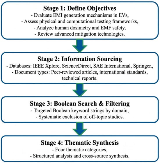
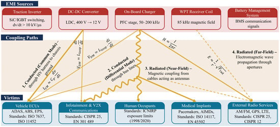
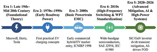
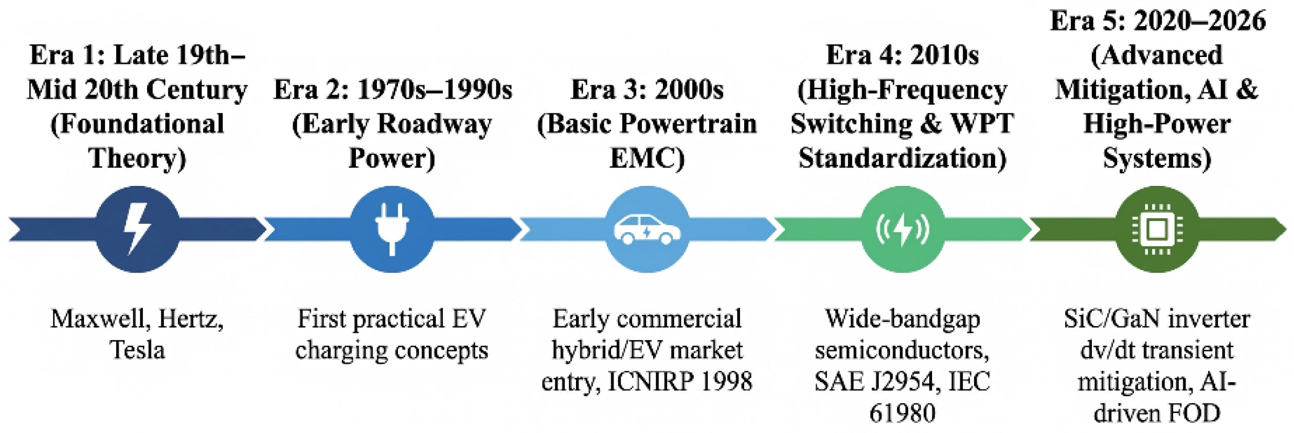
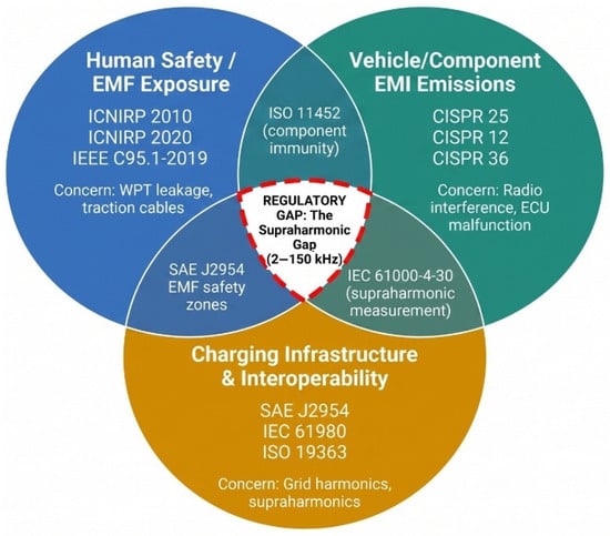
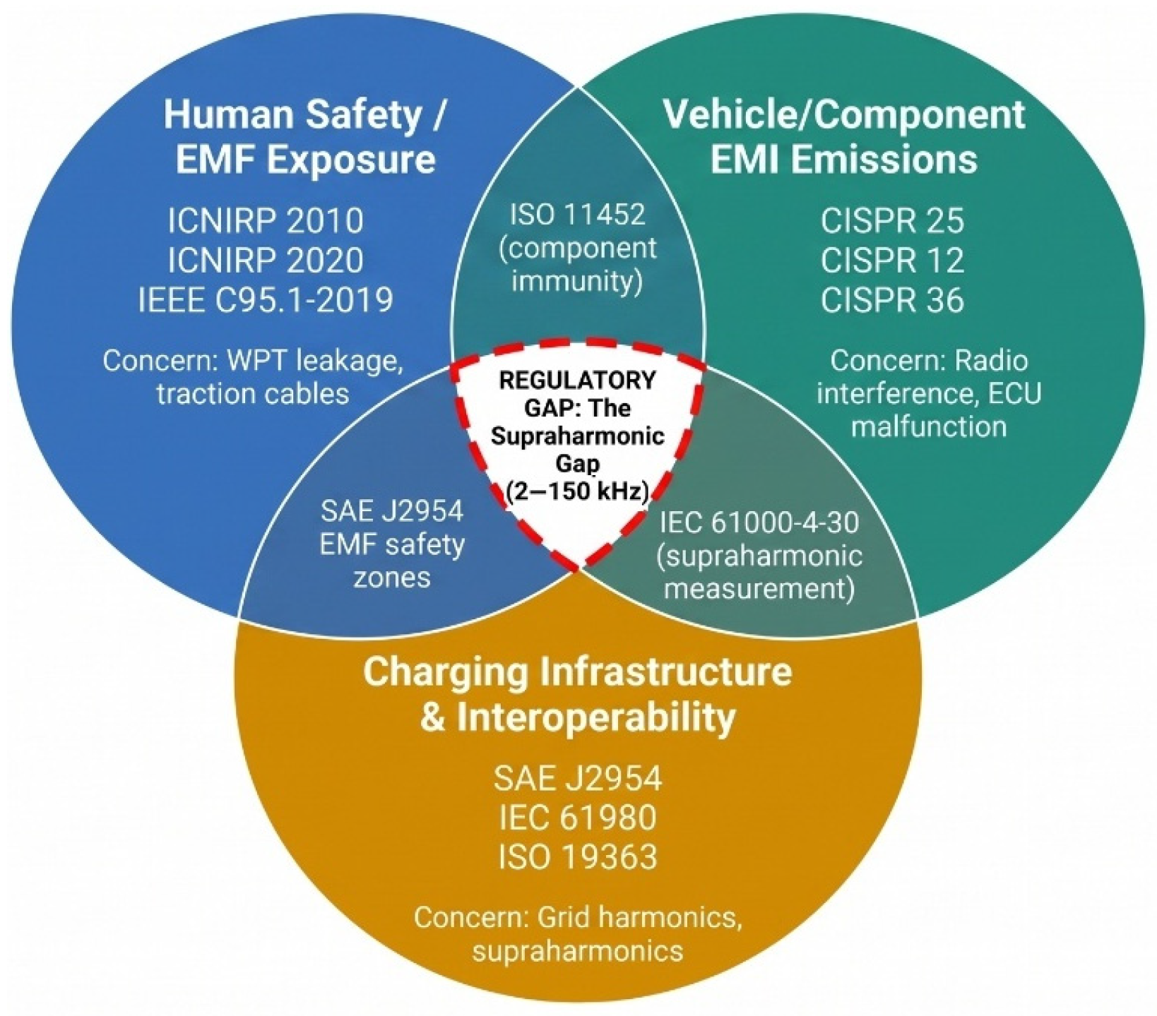
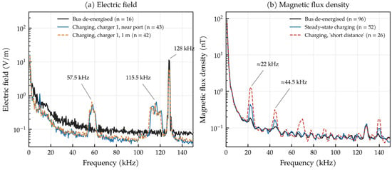
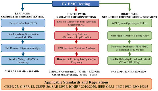

Disclaimer/Publisher’s Note: The statements, opinions and data contained in all publications are solely those of the individual author(s) and contributor(s) and not of MDPI and/or the editor(s). MDPI and/or the editor(s) disclaim responsibility for any injury to people or property resulting from any ideas, methods, instructions or products referred to in the content. |
© 2026 by the author. Licensee MDPI, Basel, Switzerland. This article is an open access article distributed under the terms and conditions of the Creative Commons Attribution (CC BY) license.