


Abstract
Concentrated Solar Power (CSP) tower systems require receiver materials capable of operating above 1000 °C to meet the efficiency targets of third-generation technologies (25–30%). Hybrid solutions, combining ceramic coatings with metallic substrates, offer promising thermomechanical stability under severe thermal cycling. This study investigates the high-temperature behavior of silicon carbide (SiC) coatings deposited on Fe-C-Al-Mo alloys under concentrated solar flux. Substrates were pre-oxidized to form a continuous 1–2 µm α-Al2O3 interlayer, serving as a chemical and mechanical buffer. SiC coatings (10–24 µm thick) were deposited via High-Temperature Chemical Vapor Deposition (HT-CVD). Characterization using XRD, SEM, EDS, and optical spectrophotometry identified cubic 3C-SiC with a globular microstructure and high compressive residual stresses (−2000 to −2400 MPa), inducing microcracking. Stress relaxation was achieved by increasing coating thickness or post-deposition annealing. Controlled oxidation formed a thin silica layer, enhancing solar absorptivity to over 90%. Accelerated thermal cycling (up to ~900 kW/m2, 1050–1200 °C) revealed that coating stability depends on SiC thickness, residual stress evolution, α-Al2O3 interlayer thickness, and cycling severity. Optimizing these parameters is essential for ensuring the long-term durability of hybrid CSP receivers.
1. Introduction
Concentrated solar power (CSP) tower systems represent a promising approach for converting solar radiation into thermal energy, which can then be used to generate electricity or provide high-temperature heat for industrial processes. However, the efficiency of current CSP technologies remains limited (9–16% for first-generation systems and 10–20% for second-generation systems), primarily due to operating temperatures restricted to approximately 600 °C [1]. These constraints are largely imposed by the performance of existing receiver materials, which degrade mechanically and oxidize at elevated temperatures. Achieving operating temperatures above 1000 °C would significantly enhance thermodynamic efficiency (25–30% for third-generation systems [1]) and expand opportunities for advanced solar energy conversion applications.
Ceramic materials, particularly silicon carbide (SiC) and silicon-infiltrated silicon carbide (SiSiC), have been extensively investigated for high-temperature solar receivers due to their exceptional thermal stability and oxidation resistance [2,3,4]. However, their use in surface receiver applications is limited by inherent brittleness and poor resistance to mechanical and thermal shocks, stemming from low fracture toughness across a wide temperature range [5]. Despite these challenges, technical ceramics offer outstanding intrinsic properties, including low density, high hardness, excellent abrasion resistance, superior oxidation resistance (especially for silicon-based ceramics), and the ability to withstand extreme temperatures, with melting points exceeding 2000 °C [6].
To leverage the advantages of ceramics while improving mechanical reliability, hybrid systems combining ceramic coatings with metallic alloys have emerged as promising candidates for next-generation CSP receivers. In these systems, ceramic coatings provide high optical absorption and thermal stability [7], while metallic substrates ensure mechanical strength and creep resistance during prolonged high-temperature exposure. Nevertheless, the mismatch in thermal expansion coefficients between ceramics and metallic alloys poses a significant challenge, often inducing residual stresses that lead to coating cracking or delamination during thermal cycling [8].
In this context, the present study explores a hybrid receiver concept based on a SiC coating deposited onto a pre-oxidized Fe–Cr–Al–Mo alloy, designed to combine high optical performance with enhanced mechanical reliability at elevated temperatures. SiC was selected for its thermal stability, its capacity to withstand temperatures up to 1200 °C before decomposition, and its excellent oxidation resistance. At high temperatures, SiC forms a protective silica (SiO2) layer that slows oxidation and shields the underlying material. It is widely used in the electrical industry for heating elements and surge conductors.
This work focuses on the role of the α-Al2O3 interlayer, formed through controlled pre-oxidation, which is shown to be a critical parameter influencing coating adhesion, residual stress development, and thermomechanical behavior. The deposition of SiC is analyzed in terms of microstructure, phase composition, optical properties, and residual stress state as a function of coating thickness. The multilayer system is then subjected to accelerated aging tests under concentrated solar flux, reaching surface temperatures up to 1200 °C using various thermal cycling strategies. Through this combined approach, the study identifies the primary degradation mechanisms such as oxidation, crack propagation, stress accumulation, and delamination. It elucidates the complex interplay between SiC thickness, interfacial oxide thickness, and thermal cycling severity, which ultimately determines the durability of SiC-coated metallic receivers for high-temperature CSP applications.
2. Materials and Methods
2.1. Materials
The receiver consists of a composite material assembly comprising a Kanthal APMT® (Fe–Cr–Al–Mo alloy provided by Sandvik group, Stockholm, Sweden) substrate, pre-oxidized to form a thin alumina (Al2O3) layer, and subsequently coated with a silicon carbide (SiC) layer.
The substrate samples (25 × 25 × 2 mm3) contain, according to the manufacturer, 21–22 at.% chromium, 5 at.% aluminum, 3 at.% molybdenum, and the balance iron [9,10]. This alloy combines the excellent oxidation resistance of FeCrAl alloys with sufficient creep strength, enabling the design of moderately loaded components up to its maximum recommended operating temperature of 1250 °C. Within this temperature range, nickel-based alloys degrade rapidly due to accelerated oxidation and grain boundary softening [11].
Prior to ceramic layer deposition, the substrate undergoes pre-oxidation. The resulting thin alumina layer (1–2 µm), obtained by oxidation in air at 1100 °C, serves as a barrier to prevent carbon inclusions in the substrate during SiC deposition. Additionally, it enhances the adhesion of the SiC coating to the metallic alloy, thereby reducing the risk of delamination or cracking during thermal cycling [11]. The intermediate alumina layer also acts as a thermal expansion accommodation layer, with a coefficient of thermal expansion intermediate between that of the metallic substrate and polycrystalline ceramics. This property helps mitigate cracking caused by thermal shocks [12].
The thin SiC layer, whose thickness depends on the coating duration, is produced in a High-Temperature Chemical Vapor Deposition (HT-CVD) reactor at 1200 °C, as detailed in Section 2.2.1. The key properties of all materials are summarized in Table 1.
Table 1.
Materials’ properties.
2.2. Methods
2.2.1. Oxidation and SiC Deposition
To form the protective aluminum oxide layer on the substrate, a uniform oxidation treatment was performed in an electric furnace at 1100 °C for 50 h in air. These oxidation conditions are selected to form a dense, continuous 2 µm α-Al2O3 alumina layer (corundum) on the substrate surface. This layer acts as a thermal stress accommodator between the metallic substrate and the SiC coating, while chemically stabilizing the interface, thereby enhancing the deposit adhesion [6,17]. The oxide thickness was estimated from mass gain before and after oxidation.
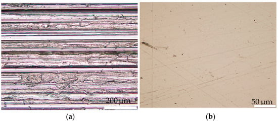
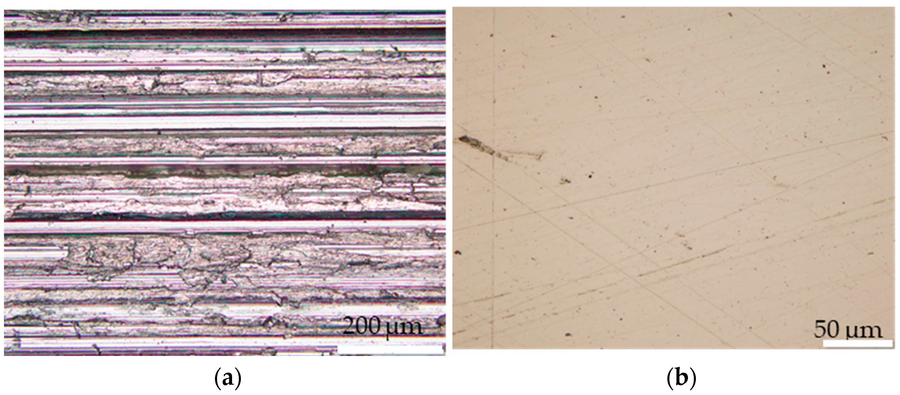
As-received samples exhibited coarse surface scratches (Figure 1a). To ensure uniform deposition, the samples were polished prior to oxidation. Initially, a rough polishing step was performed using SiC abrasive paper to remove deep scratches, followed by successive finer polishing steps. The final polishing stage (Figure 1b) produced a mirror-like surface using 1 µm diamond paste. After polishing, the samples were sequentially cleaned with acetone and ethanol, then dried in an oven at 80 °C for 2 h.
Figure 1.
Microscopic images of (a) non-polished sample and (b) polished sample.
The oxide thickness can be estimated from the measured mass gain (Δm), which corresponds solely to the oxygen incorporated during oxidation, as the aluminum required to form alumina originates from the alloy itself. Given the molar mass of alumina (102 g/mol) and the mass of oxygen per mole of alumina (MO = 3 × 16 g/mol = 48 g/mol), every 48 g of absorbed oxygen produces 102 g of Al2O3. Assuming a uniform oxide layer, the mean oxide thickness (h) is calculated as follows:
where ∆m is the mass gain, ρ is the density of alumina, L and l are, respectively, the length and the width; and are, respectively, the molar masses of alumina and oxygen. g and mm.
The deposition process employed is High-Temperature Chemical Vapor Deposition (HT-CVD), which has been described in greater detail elsewhere [18,19]. The experimental setup consists of a graphite susceptor holding the sample, heated by induction. The susceptor temperature is monitored using a thermocouple, while the sample temperature is measured with an infrared pyrometer.
Silicon carbide (SiC) coatings were synthesized at 1190 °C using silane (SiH4) and propane (C3H8) as precursor gases. The deposition rate is approximately 20 µm/h, yielding cubic silicon carbide (β-SiC or 3C-SiC). Samples 1, 2, and 4 were deposited with a continuous injection of SiH4, C3H8, and Cl2. For Sample 3, the deposition process involved alternating injections: 15 min of SiH4 + C3H8 + Cl2, followed by 1 min of SiH4 + Cl2 only, and then another 15 min of SiH4 + C3H8 + Cl2. The characteristics of all samples are summarized in Table 2.
Table 2.
SiC deposition conditions.
Unlike the oxidation process, the SiC layer is directly deposited onto the substrate surface. Consequently, the measured mass gain corresponds exclusively to the mass of the deposited SiC. Since deposition occurs on a single face with a surface area and given that represents the mass gain associated with SiC deposition, the volume of deposited SiC () can be expressed as
Assuming a uniform coating, the mean SiC thickness is
where V is the volume, ρ is the density, Δm is the mass gain, and S is the surface area; L and l are the length and width, respectively. The uncertainty on hSiC is calculated by the following equation:
With g as the uncertainty in weighing and mm as the uncertainty in length.
2.2.2. X-Ray Diffraction sin2ψ Method
The classical XRD sin2ψ technique [20] is a non-destructive approach widely used to evaluate equi-biaxial in-plane stresses in polycrystalline materials. Although robust for bulk materials, this approach exhibits major limitations when applied to thin films and coatings: the X-ray penetration depth, on the order of a few micrometers, leads to a significant contribution from the substrate; moreover, the method assumes a homogeneous stress field over the probed depth, an assumption that is no longer valid in the presence of the strong stress gradients typically found in thin coatings.
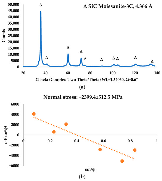
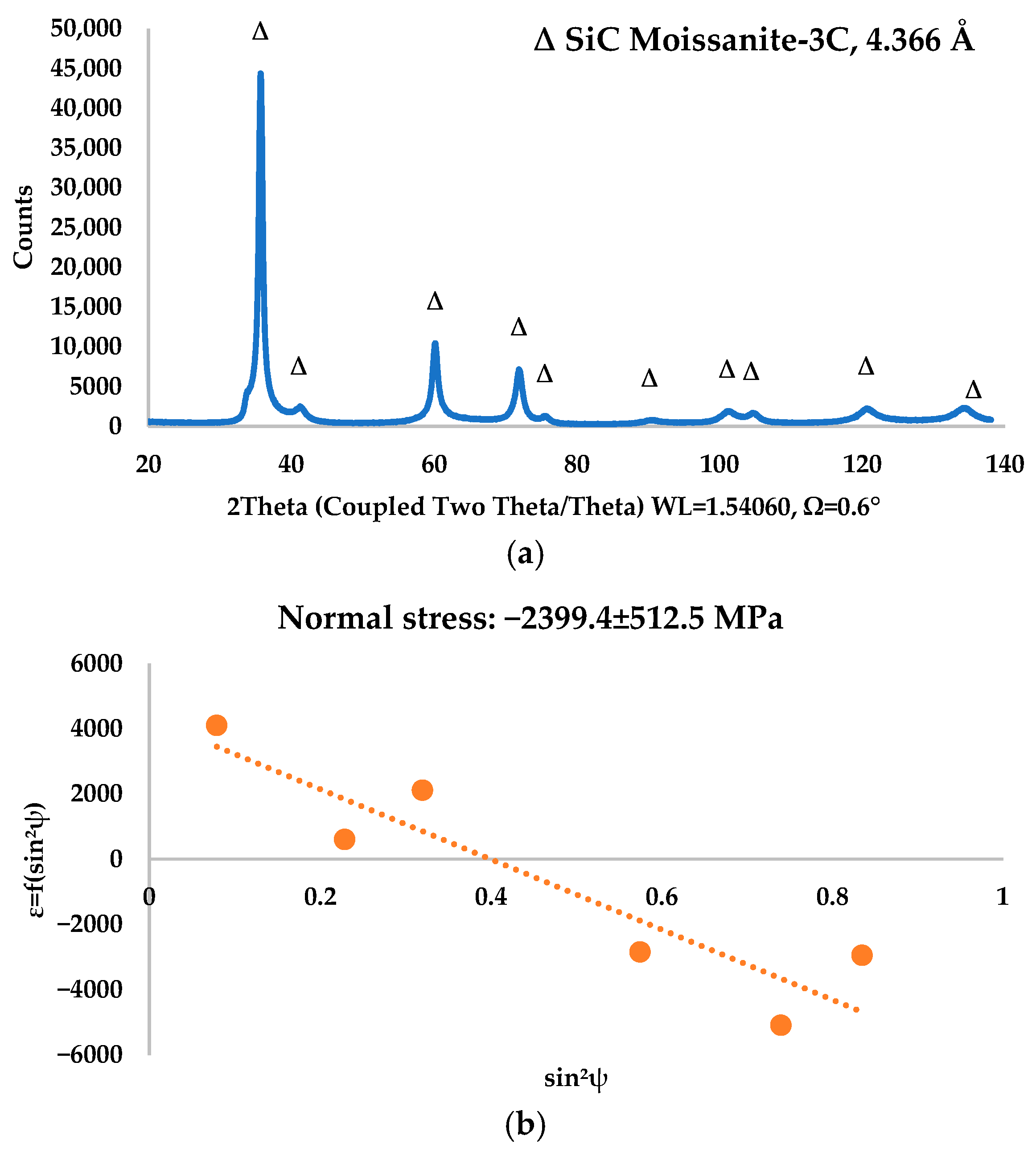
To overcome these limitations, a method based on grazing incidence X-ray diffraction (GIXRD) combined with the sin2ψ* formalism has been developed by Jun Pen [21,22] for the analysis of residual stresses in thin films. The key principle of this geometry lies in the use of a low and fixed incidence angle Ω (Figure 2a), which is decoupled from the Bragg angle. This configuration allows the X-ray penetration depth to be reduced and accurately controlled, thereby enhancing the diffraction signal originating from the coating while minimizing the contribution from the substrate. Within this framework, the elastic strain measured by diffraction remains directly related to the macroscopic stress field through the general relationship:
where is the strain measured along the direction defined by the angles and , are the components of the stress tensor, and are diffraction stress factors that account for the asymmetric geometry induced by grazing incidence. The angle * represents the actual angle between the surface normal and the normal to the diffracting crystallographic planes. For a quasi-isotropic material under a plane-stress condition, and for an analysis direction , this expression reduces to a form analogous to the classical method:
where and are the X-ray elastic constants associated with the family of planes. The residual stress can therefore be directly determined from the slope of the linear relationship between and sin2ψ* (Figure 2b).
Figure 2.
Grazing XRD principle: (a) peaks’ position and (b) determination of stress from ε = f(sin2ψ) curve.
The diffractometer used in this study for θ/2θ acquisitions, as well as for coplanar grazing-incidence X-ray diffraction (GIXRD) measurements, is an Empyrean Series 3 model from Malvern Panalytical. The X-ray radiation source is a Cu anode, resulting in the use of the Cu Kα wavelength (λ = 1.5418 Å).
For the analysis of diffraction patterns, all (or nearly all) {hkl} plane families of the studied phase were employed. However, families with excessively low intensities or those with positions too close to one another, leading to convoluted peak contributions, were excluded (a phenomenon particularly relevant for alumina in this study).
For SiC-3C, the peak positions corresponding to the {111}, {220}, {311}, {331}, {420}, and {422} plane families were systematically included in the calculations. The {200}, {222}, and {400} peaks, which are poorly defined, were omitted. Depending on the sample and the observed line shifts, the contribution of the {511} peak located near the scan limit was selectively considered.
The X-ray elastic constants used in this analysis were recalculated using a “quasi-isotropic” model based on the stiffness coefficients Cij (specifically C11, C12 and C44 for the cubic SiC-3C phase). These values were derived from Petska’s work [23], which focuses on the specific case of strongly <111>-textured SiC-3C deposits a configuration that aligns with the characteristics of our samples.
2.2.3. Total Absorptivity Calculation
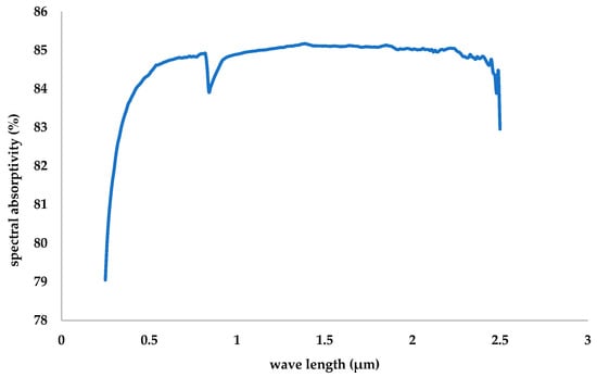
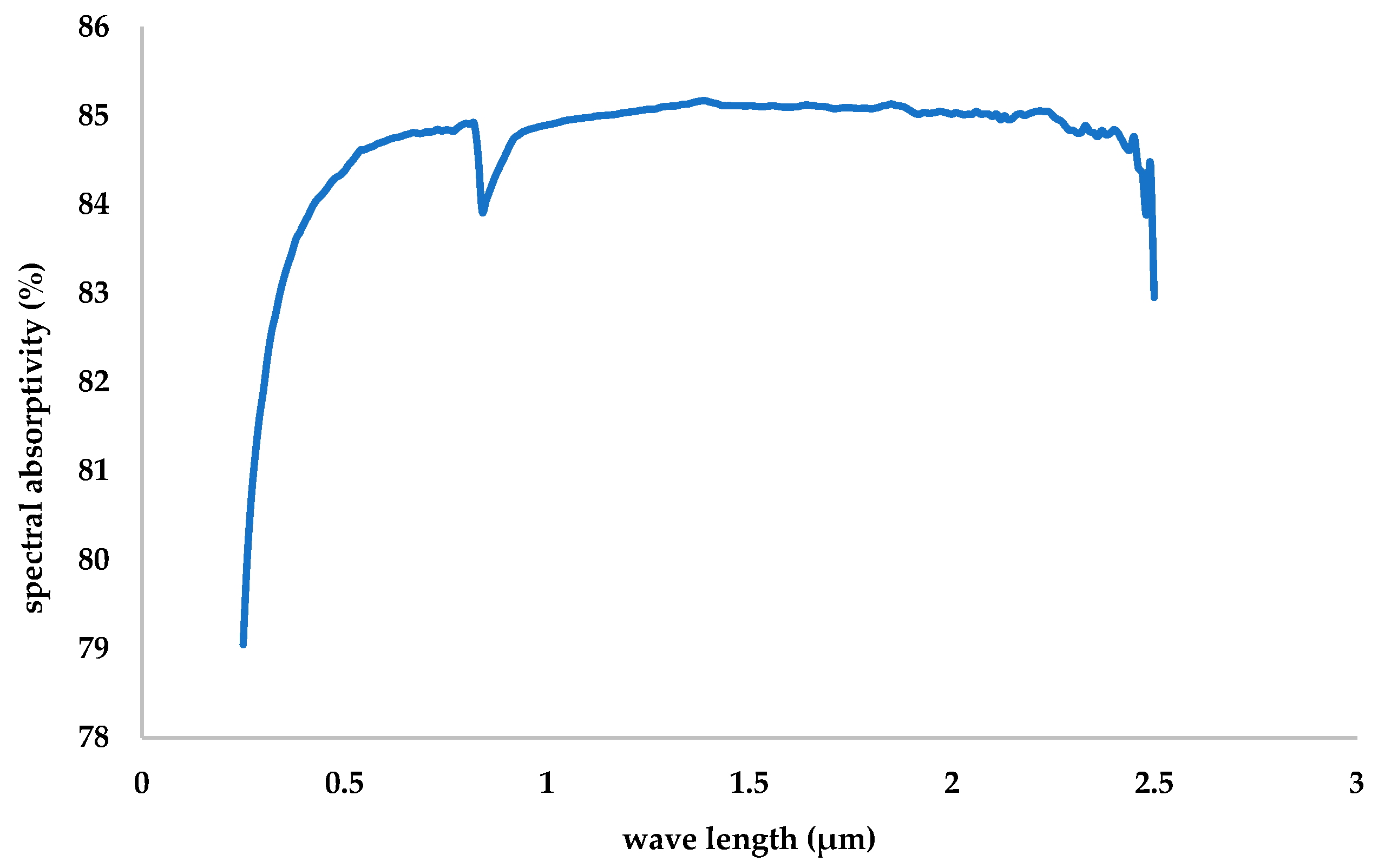
The solar absorptivity considered in this study, denoted as αsol, is defined as the ratio of absorbed solar radiation to incident solar radiation from a quasi-normal direction. This direction corresponds to an angle of 8°, the minimum measurable angle achievable with the experimental setup. This parameter is determined from the spectral reflectivity, R(λ), measured using an integrating sphere with an internal diameter of 150 mm, coated with Teflon. The standard reference material is Spectralon®, which exhibits a reflectance of 99% and is calibrated by LabSphere. Given that the sample is assumed to be opaque across the entire investigated wavelength range, its transmittance is considered negligible. The normal spectral absorptivity, calculated as 1 – R(λ), is then weighted using the ASTM G173-03 reference solar spectrum for direct normal solar irradiance, Gsol(λ), at an air mass of AM1.5 [24]. The integration is performed over the wavelength range from λ1 = 280 nm to λ2 = 2500 nm (Figure 3).
Figure 3.
Example of spectral absorptivity/emissivity of SiC layer (visible).
2.2.4. Aging Setup and Procedure
- Experimental Setup
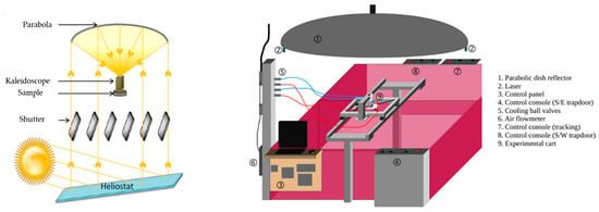
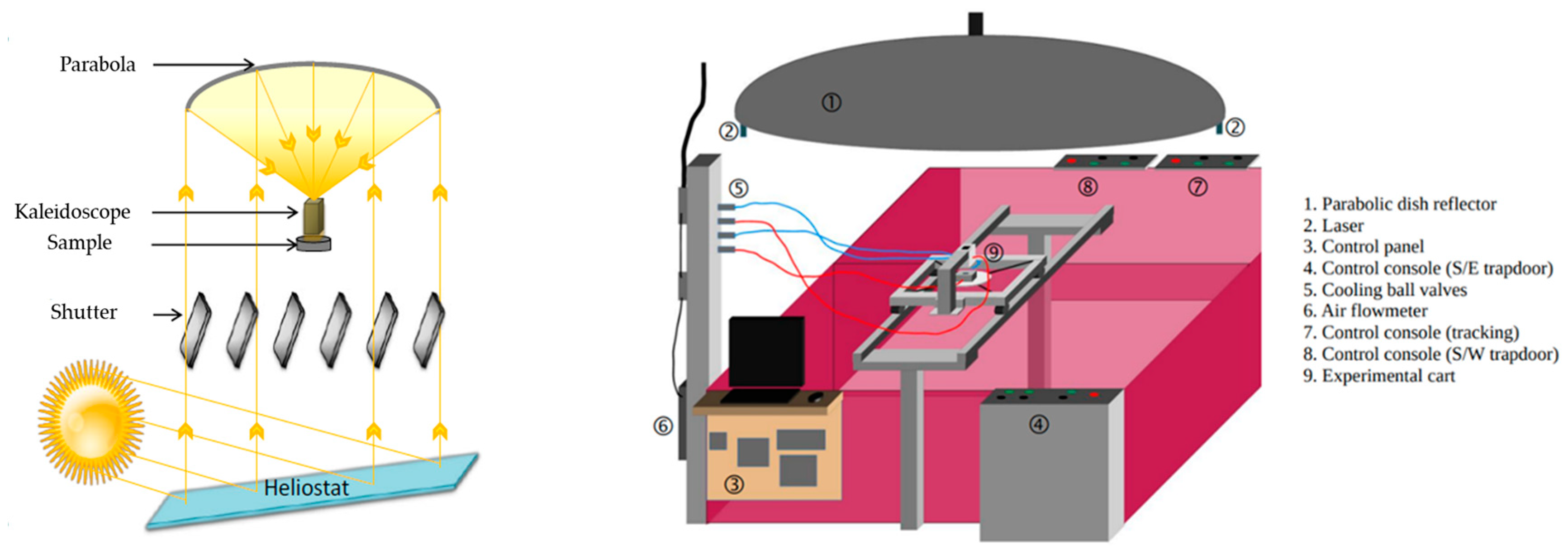
The accelerated aging tests were conducted using the Solar Accelerated Aging Facility (SAAF) (Figure 4), located at the PROMES-Odeillo laboratory. Originally designed by Antoine Boubault during his PhD (2013) [25] to investigate the aging of Inconel 625 samples coated with Pyromark paint at temperatures ranging from 250 °C to 540 °C, the facility was later utilized by Reine Reoyo-Prats (2020) [26] to study the aging of materials such as Inconel 617, Haynes 230, T91, VM12, and T22 at a maximum temperature of 700 °C under a solar flux of 700 W/m2.
Figure 4.
The Solar Accelerated Aging Facility (SAAF) and its different components.
The SAAF comprises a solar concentration system featuring a mobile horizontal heliostat and a fixed parabolic mirror positioned 25 m above. The system also includes a kaleidoscope to homogenize the concentrated solar flux, as well as movable shutters or blades to regulate the incident flux on the sample. All components are integrated with a control system and a data acquisition system to monitor the aging experiments and record the resulting data. The kaleidoscope and sample holder are cooled by water and compressed air, respectively.
The concentration system incorporates a 6 m × 4.5 m heliostat equipped with a two-axis solar tracking system, which reflects direct solar radiation onto a 900 W parabolic mirror. This mirror concentrates the radiation by a factor of approximately 15,000. The parabolic mirror has a diameter of 1.5 m, with a focal point located 635 mm from its center and a focal spot of roughly 10 mm in diameter. Further details of the experimental setup are provided in [25].
- Experimental Procedure
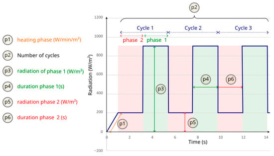
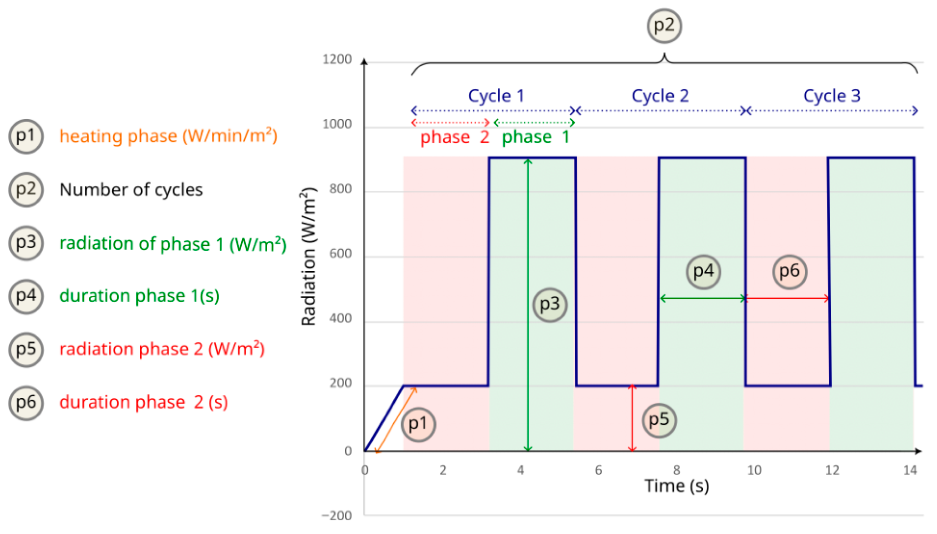
The objective of these experiments is to simulate the accelerated aging of the multilayer samples by subjecting them to controlled thermal cycles using the parabolic solar concentrator (Figure 5). During the experiments, data are precisely recorded while the solar flux is modulated. The parabolic concentrator focuses sunlight onto the sample surface. A pyrometer, aligned with the sample’s front face, measures the surface temperature, while a thermocouple in contact with the rear face records the backside temperature.
Figure 5.
Illustration of typical thermal cycling with the SAAF.
Each thermal cycle begins with a ramp-up phase (p1), during which the temperature is gradually increased to the target level. This is followed by a high-temperature holding phase (p3), where the sample is exposed to maximum radiation for a specified duration (p4). The cycle concludes with a cooling phase (p5), during which the sample is subjected to minimal radiation (0 kW/m2) for a shorter period (p6). The full cycle is repeated multiple times, as defined by the number of cycles (p2).
Table 3 summarizes the thermal cycling conditions applied to each sample.
Table 3.
The solar accelerated aging conditions.
Sample 1 served as the initial specimen tested under concentrated solar flux. Based on its observed behavior and the resulting data, the experimental conditions were subsequently optimized for the remaining samples. The goal was to conduct aging tests under identical conditions for Samples 2, 3, and 4.
Samples 2 and 3 were deposited under the same conditions; however, Sample 2 underwent an additional annealing treatment to form a protective silica layer. Sample 4, in contrast, was deposited to achieve a coating thickness approximately twice that of Sample 2.
The following sections detail the responses of each sample during solar aging and present a comparative analysis, taking into account their respective structural and compositional characteristics.
3. Results and Discussions
This section presents the deposition results, followed by an analysis of the solar aging outcomes. Depending on the sample and deposition conditions, each specimen may exhibit distinct structural, morphological, or functional characteristics, which are compared and discussed in detail.
3.1. Coating Characterization After SiC Deposition
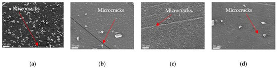
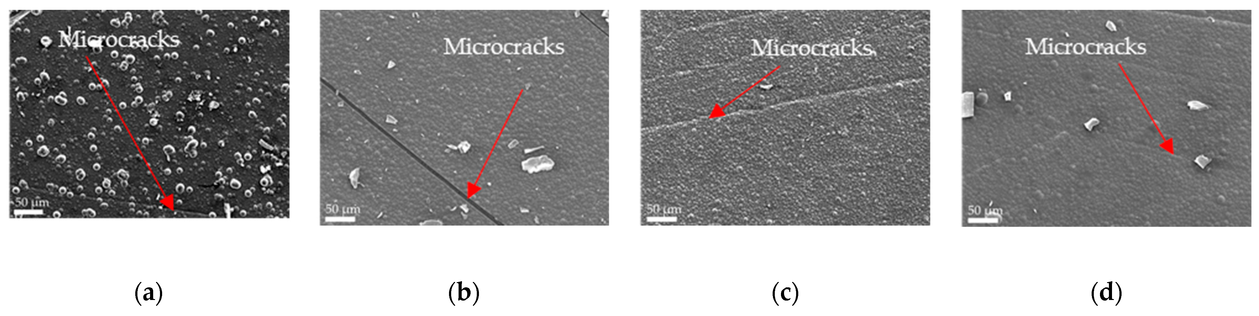
SEM observations reveal that all coatings exhibit a characteristic globular SiC microstructure (Figure 6), consistent with previous reports for similar deposition conditions [16]. This morphology remains unchanged regardless of substrate type, α-Al2O3 thickness, or coating thickness, suggesting that the growth mechanism is largely independent of these parameters. However, microcracks are systematically observed post-deposition (indicated by the red arrow), particularly in thinner SiC coatings deposited on the thinnest oxide layers. This indicates that the combined effect of high compressive stresses within the SiC layer and limited strain accommodation at the SiC/α-Al2O3 interface likely promotes crack initiation during cooling.
Figure 6.
SEM images after SiC deposition of (a) sample 1, (b) sample 2, (c) sample 3 and (d) sample 4.
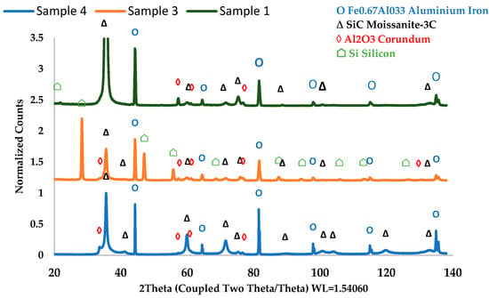
EDS analysis conducted post-deposition confirms that all coatings are primarily composed of SiC. Samples 1, 2, and 4 exhibit nearly identical compositions (approximately 45 at. % C and 47 at. % Si), demonstrating excellent reproducibility of the deposition process. The slight deviation from the ideal 1:1 stoichiometry—indicating a slight silicon excess—is corroborated by XRD analysis (Figure 7. Extending the deposition time (as in Sample 4) does not significantly alter the chemical composition when deposition conditions remain constant. In contrast, Sample 3 displays a more pronounced silicon excess (45 at. % C and 49 at. % Si). This discrepancy is attributed to the alternating deposition process, which introduces a thin silicon layer between successive SiC depositions, resulting in a modest increase in silicon content (Figure 7). The remaining elemental content originates from the α-Al2O3 interlayer (Al, O) and the metallic substrate (Al, O, Mo, Fe, etc.).
Figure 7.
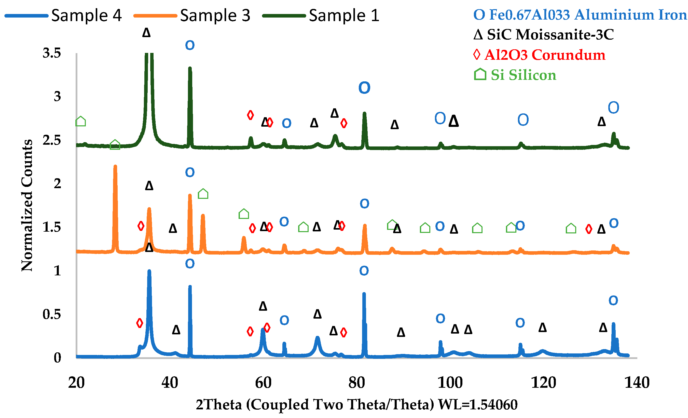
XRD patterns (measurement in Bragg–Brentano geometry).
XRD analyses (θ/2θ measurements) confirm the formation of cubic 3C-SiC (PDF 00-029-1129, space group F-43m, lattice parameter 4.366 Å), with a preferred (111) orientation observed in all samples (Figure 7). Additional diffraction peaks correspond to the α-Al2O3 interlayer (PDF 04-004-2852, space group R-3cH, 4.775 Å) from the pre-oxidized APMT substrate, as well as the metallic substrate itself (PDF 04-003-7166, space group Im-3m, 2.888 Å). The measured lattice parameter of the SiC phase (~4.36 Å) aligns with literature values [16]. For Sample 3, the presence of silicon diffraction peaks (PDF 00-27-1402, space group Fd-3m, 5.453 Å) further supports the EDS observations of a silicon-rich composition.
Residual stresses within the SiC coatings were quantified using the sin2ψ XRD method. All coatings exhibit high compressive residual stresses, ranging from −2027 MPa to −2399 MPa for the 30 min depositions. These stress levels approach the compressive strength limits reported for SiC, explaining the microcracking observed post-deposition. Sample 1, featuring a 9.6 µm SiC coating on a thin α-Al2O3 interlayer (1.1 µm), exhibits one of the highest compressive residual stresses (−2399 ± 513 MPa). Sample 2, with a slightly thicker SiC layer (11.5 µm) and alumina interlayer (1.9 µm), shows a comparable stress level (−2386 ± 361 MPa). Given the associated uncertainties, these stresses are statistically similar, suggesting that modest increases in SiC and alumina thicknesses do not significantly relieve stress at this stage. In contrast, Sample 3, comprising a 12.8 µm SiC coating and the thickest α-Al2O3 interlayer (2.2 µm), demonstrates a marked reduction in residual stress (−2028 ± 379 MPa) compared to the stress measured after substrate pre-oxidation (−2761 ± 428 MPa). This reduction suggests that a thicker oxide interlayer facilitates stress redistribution and partial relaxation at the SiC/Al2O3 interface, potentially aided by the silicon interlayer introduced during deposition. A similar trend is observed in Sample 4, deposited on a thin alumina interlayer (1.1 µm) but with a significantly thicker SiC layer (23.8 µm). The measured residual stress (−2054 ± 296 MPa) is lower than that of thinner SiC coatings, indicating that stress relaxation can also occur within the SiC layer itself once a critical thickness is exceeded.
Overall, these results demonstrate that while high compressive stresses are intrinsic to the SiC deposition process, their magnitude is influenced by the combined effects of interlayer thickness, SiC coating thickness, and potentially deposition gas alternation. These parameters govern stress redistribution mechanisms, occurring either at the interface or within the SiC layer. However, some observed differences remain within the limits of experimental uncertainty, warranting further investigation for definitive confirmation.
The deposition of SiC coatings significantly enhances solar absorptivity. For Sample 1, absorptivity increases from 74.7% for the pre-oxidized alumina surface to 81.5% following SiC deposition. Further improvement is achieved through controlled oxidation.
To investigate its influence on radiative properties, Sample 2 underwent a post-deposition annealing treatment in an electric furnace. After oxidation at 1100 °C for 4 h, solar absorptivity increased substantially, from 84% to 94%. SEM observations confirm that the globular SiC microstructure remains intact after oxidation. EDS analyses reveal the formation of a silica-rich surface layer (composition: 25 at. % C, 50 at. % Si, 23 at. % O, and 2 at. % from the substrate, including Al, Fe, and Mo). Additionally, the annealing treatment partially masks microcracks formed during deposition.
Overall, these results demonstrate that the SiC deposition process on pre-oxidized substrates is highly reproducible, enabling precise control of coating thickness while maintaining a consistent microstructure. However, the thermomechanical state of the coatings is strongly influenced by the combined effects of SiC thickness, α-Al2O3 interlayer thickness, and the alternating supply of deposition gases. Thin oxide layers promote high compressive stress and early crack formation, whereas thicker oxide layers and/or thicker SiC coatings facilitate partial stress relaxation. These interfacial and stress-related effects are expected to play a critical role in coating stability during subsequent thermal cycling under concentrated solar flux. However, further investigations are currently underway to validate or refine these observations.
3.2. Thermal Cycling Under Concentrated Solar Flux
Thermal cycling tests under concentrated solar flux were conducted to evaluate the high-temperature performance of the SiC coatings and to establish correlations between their behavior and the characteristics determined during deposition. Key parameters included coating thickness, residual stress state, surface condition, and thickness of the pre-oxidized α-Al2O3 interlayer. This oxide layer is critical for interfacial adhesion, stress accommodation, and thermomechanical stability during cyclic high-temperature exposure.
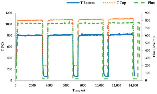
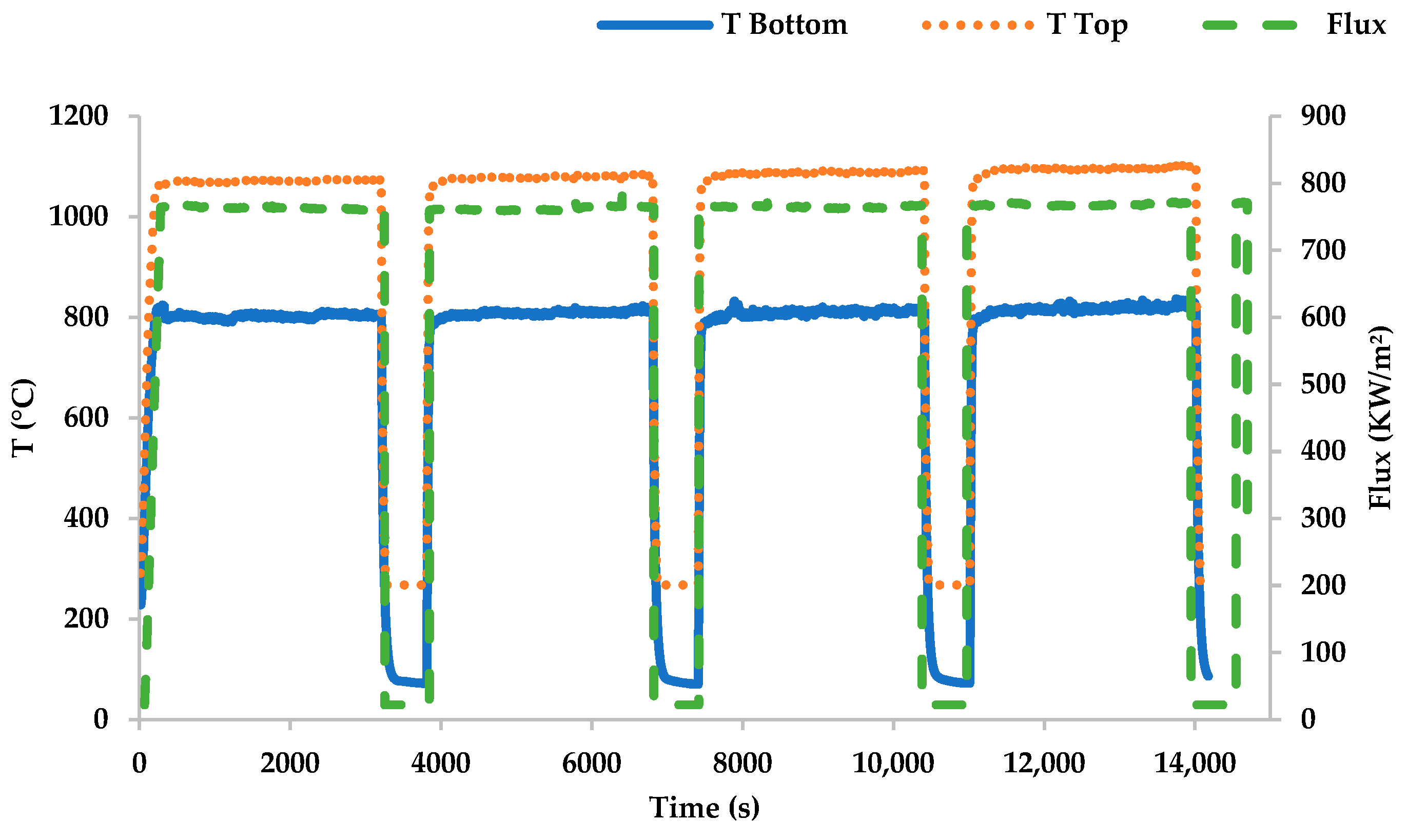
In the first solar-flux aging test, Sample 1 was subjected to four thermal cycles, each lasting 1 h (Table 3). The maximum incident solar flux reached approximately 770 kW/m2, raising the illuminated surface temperature to about 1100 °C (Figure 8). The rear face, cooled by compressed air at a flow rate of 0.9 g/s, reached a maximum temperature of approximately 830 °C, as recorded by a thermocouple.
Figure 8.
Example of thermal cycles: four thermal cycles, 60 min each (4 h in total).
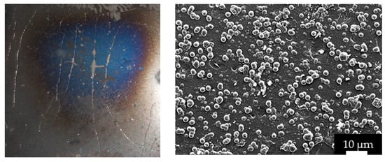
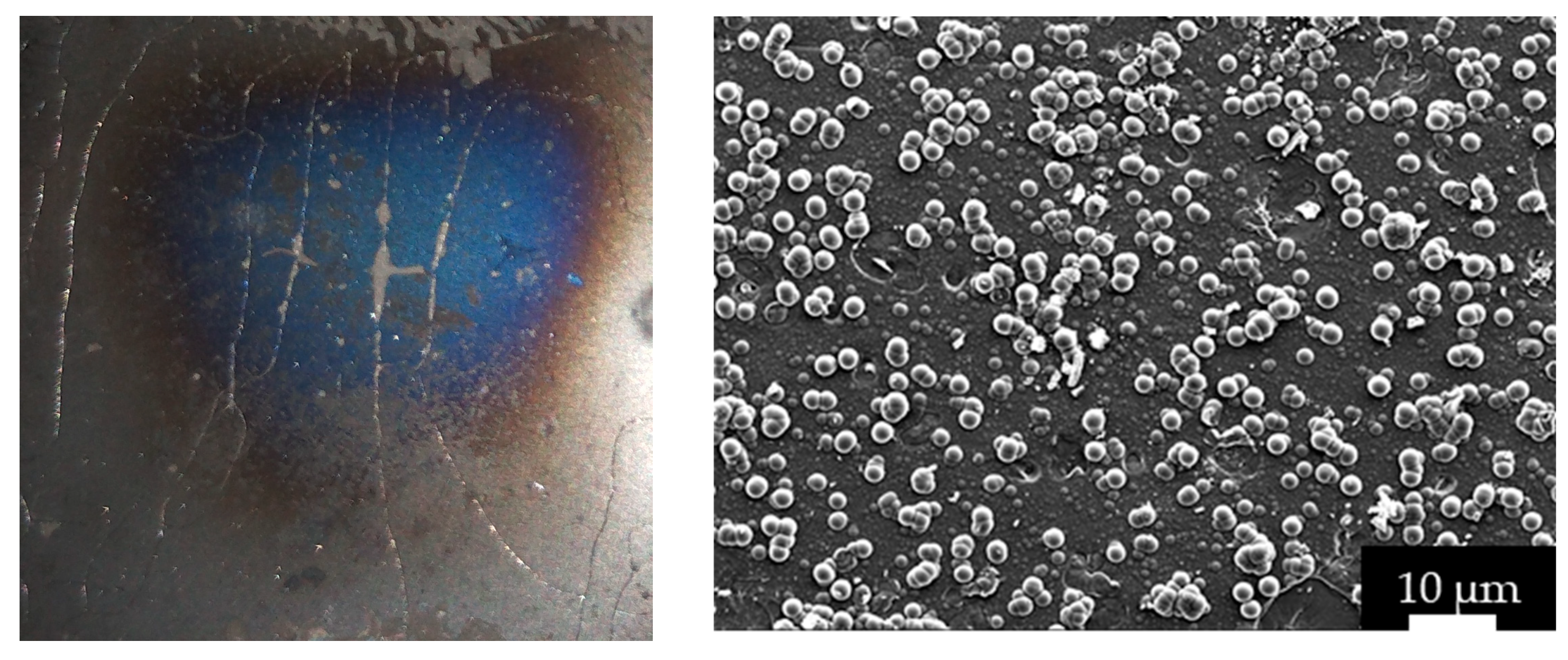
Following thermal cycling, a bluish discoloration was observed at the center of the sample surface, indicating the formation of SiO2 due to partial oxidation of the SiC coating (Figure 9). EDS analysis confirmed the presence of a mixed SiC/SiO2 layer, with atomic concentrations of 48% Si, 24% C, and 26% O. The formation of this thin silica layer resulted in a significant increase in total solar absorptivity, from 81.5% for the as-deposited coating to 91.6% post-aging. Residual stress measurements conducted after thermal cycling revealed substantial relaxation, with compressive stress decreasing to −1127 ± 328 MPa from the as-deposited state value of −2399 ± 512.5 MPa. Despite this relaxation, crack propagation was still observed under concentrated solar flux. This behavior is attributed to the combined effects of the initially high residual stress, the relatively thin SiC coating, and the very thin α-Al2O3 interlayer (1.1 µm), which offers limited strain accommodation at the SiC/Al2O3 interface during thermal cycling.
Figure 9.
Sample 1 after 4 thermal cycles (macroscopic photo).
Following deposition and post-deposition annealing, Sample 2 was subjected to 15 thermal cycles, each lasting 20 min. However, the test was terminated after the 6th cycle due to coating delamination. During the cycles, the temperature on the illuminated surface reached approximately 1200 °C, while the rear-face temperature climbed to about 1060 °C. These elevated temperatures are attributed to the higher solar absorptivity resulting from the pre-formed silica layer, combined with the increased incident solar flux during the test day (990 kW/m2). Additionally, Sample 2 features a thicker α-Al2O3 interlayer (1.9 µm) compared to Sample 1, which may enhance interfacial continuity and partially alleviate stress concentrations.
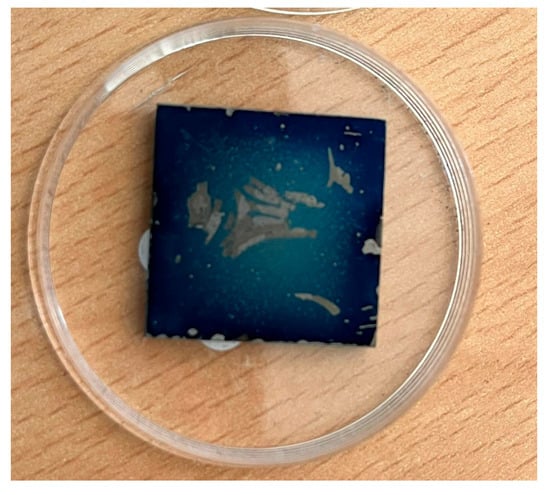
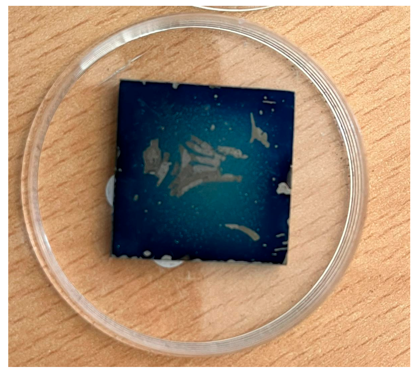
Under these conditions, evaporation phenomena were observed after the fourth thermal cycle. By the sixth cycle, partial delamination of the coating occurred at the center of the sample (Figure 10). These findings underscore the strong interdependence between deposition-induced surface chemistry, optical performance, oxide interlayer thickness, and thermomechanical stability. They also highlight the critical need to adapt cooling strategies when employing highly absorbing coatings. Residual stress was not evaluated because of the coating failure.
Figure 10.
Delamination of SiC coating after thermal cycling of sample 2 (macroscopic photo).
Three series of thermal cycling tests were conducted on Sample 3 over a total duration of 13 h and 24 min to evaluate the influence of cycle duration and thermal shock severity.
In the first series, the sample underwent 15 thermal cycles, each lasting 20 min (15 min at high temperature followed by 5 min of cooling), for a total duration of 5 h. The illuminated surface temperature exceeded 1050 °C, while the rear-face temperature reached approximately 700 °C under an average incident solar flux of 990 kW/m2. The cooling air flow rate was maintained at 1.2 g/s. Evaporation phenomena were observed at the beginning of the first cycle and again during the seventh cycle. A temperature drop of approximately 35 °C was recorded during the sixth cycle, suggesting a transient change in surface conditions or heat transfer.
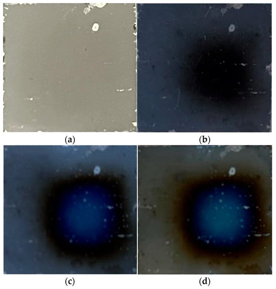
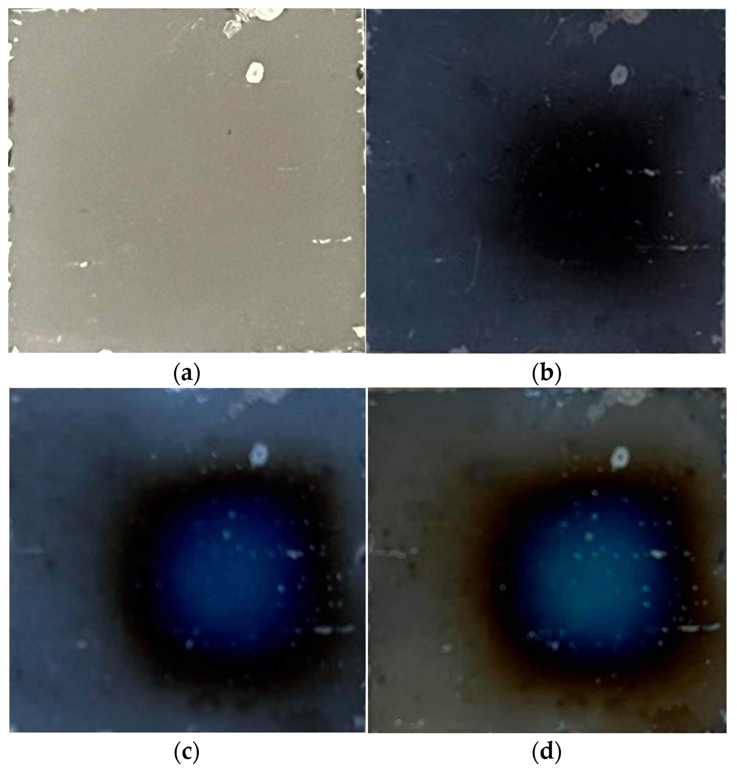
After this first series, no significant oxidation of the SiC coating was detected, and only minor, localized delamination was observed (Figure 11b). No macroscopic deformation occurred. This relative stability can be attributed to the thicker α-Al2O3 interlayer (2.2 µm), which likely enhanced interfacial stress accommodation and delayed damage initiation despite the high residual stresses measured post-deposition. The alternating SiC/Si/SiC deposition may also have contributed to this stability; further studies are underway to validate these hypotheses.
Figure 11.
Evolution of the surface of sample after each series of cycling: (a) bare SiC, (b) SiC after the 1st series, (c) SiC after the 2nd series, and (d) SiC after the 3rd series (macroscopic photo).
Given the positive performance during the first series, a second series of 44 faster thermal cycles was conducted, each lasting 6 min (5 min at high temperature and 1 min of cooling), for a total duration of 4 h and 24 min. Under a very high average solar flux of 990 kW/m2, the illuminated surface temperature reached about 1100 °C, while the rear-face temperature ranged between 400 °C and 550 °C. The lower rear-face temperature compared to the first series may be related to thermocouple dysfunction, as the cooling air flow rate remained unchanged.
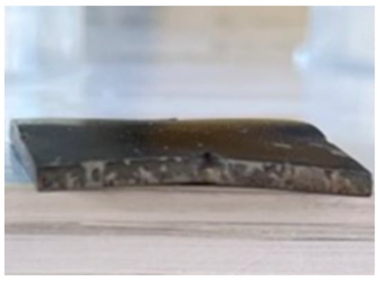
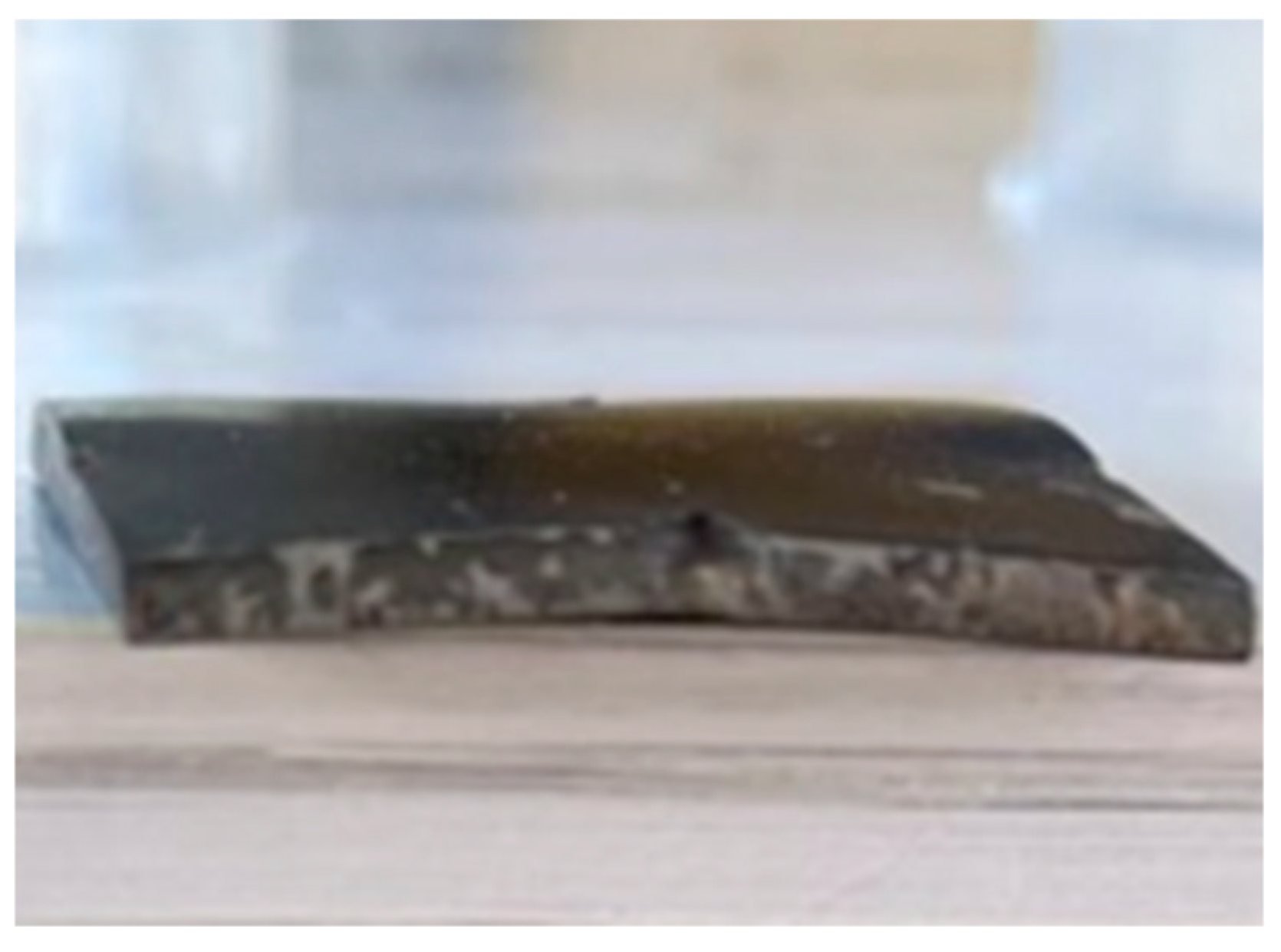
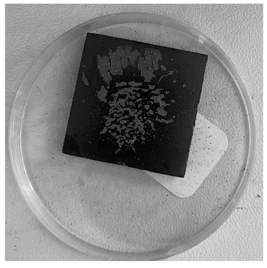
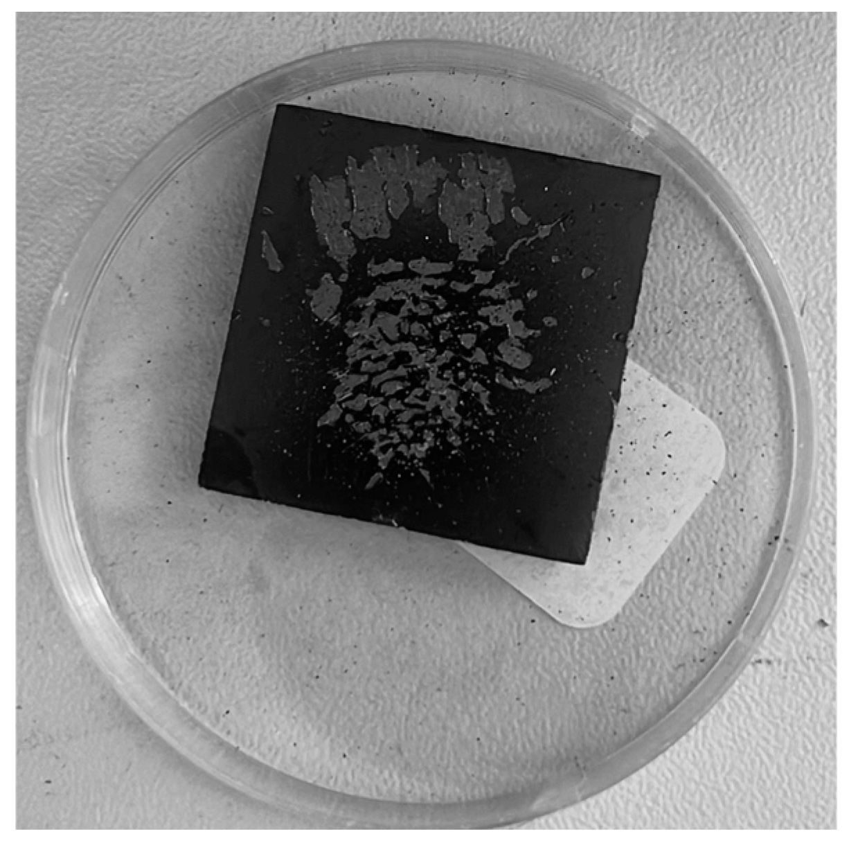
At the end of this second series, partial oxidation of the SiC coating was observed at the center of the sample, along with a slight propagation of the delamination initially detected during the first series (Figure 11c). Additionally, significant macroscopic deformation of the sample was observed, likely due to the rapid cycling conditions and increased severity of thermal shocks (Figure 12).
Figure 12.
Observed deformation after the second series of rapid cycling (macroscopic photo).
A third series of four longer thermal cycles was conducted, each lasting 1 h (50 min at high temperature followed by 10 min of cooling), under the same incident solar flux of 990 kW/m2. The illuminated surface temperature again reached approximately 1100 °C, while the rear-face temperature could not be recorded due to thermocouple failure.
During this series, partial oxidation of the SiC coating continued, while crack propagation occurred at a slower rate (Figure 11d). Following the third series, residual stress increased to −2459 ± 387 MPa, surpassing the stress measured post-deposition. This stress buildup accounts for the observed increase in delamination and crack propagation, demonstrating that repeated thermal cycling can induce stress re-accumulation, even in the presence of a thicker oxide interlayer.
Sample 4, featuring a thicker SiC coating (23.8 µm) but a relatively thin α-Al2O3 interlayer (1.1 µm), was subjected to six thermal cycles, each lasting 20 min (15 min at high temperature followed by 5 min of cooling). The illuminated surface temperature reached approximately 1200 °C under an incident solar flux of 990 kW/m2, while the rear-face temperature exceeded 1040 °C, significantly higher than that observed for the other samples. This behavior is attributed to the very low cooling air flow rate (0.1 g/s), intentionally selected to simulate conditions with minimal effective cooling.
Under these extreme conditions, coating delamination occurred after six cycles (Figure 13), with evaporation observed as early as the first cycle. The failure of the coating, despite its increased thickness, demonstrates that thickness alone is insufficient to ensure stability under such severe thermal conditions. This behavior suggests limited interfacial adhesion, potentially exacerbated by the formation of volatile species due to interfacial reactions between SiC and the α-Al2O3 layer at very high temperatures.
Figure 13.
Sample 4 after thermal cycling (macroscopic photo).
Additionally, the combination of extremely high temperatures, limited cooling, and a thin α-Al2O3 interlayer likely resulted in poor stress accommodation, further promoting interfacial degradation. This degradation may be linked to the formation of volatile species at the SiC/Al2O3 interface, particularly since SiC oxidation is known to occur at temperatures between 1000 °C and 1100 °C.
Since CO is a gaseous species, its formation can account for the observed evaporation phenomena. Residual stress was not evaluated because of the coating failure or delamination.
In Table 4, all results are summarized to provide an overall view.
Table 4.
Table of all important results.
4. Conclusions
This study investigated the deposition, characterization, and solar cycling of SiC/Al2O3/Fe–Cr–Al–Mo multilayer coatings designed for high-temperature concentrated solar power (CSP) receiver applications. The thermally grown α-Al2O3 interlayer proved essential in ensuring chemical compatibility and adhesion between the Fe–Cr–Al–Mo substrate and the SiC ceramic coating, while also playing a critical role in accommodating thermomechanical stresses at temperatures exceeding 1000 °C.
Using High-Temperature Chemical Vapor Deposition (HT-CVD), we achieved the reproducible synthesis of homogeneous SiC coatings with controlled thicknesses ranging from 10 to 24 µm. All coatings exhibited a characteristic globular 3C-SiC microstructure and high compressive residual stresses (−2000 to −2400 MPa), which accounted for the systematic presence of microcracks in the as-deposited state. The SiC thickness, thickening the α-Al2O3 interlayer, or employing an alternating SiC/Si deposition process, suggests a relaxation in stress, underscoring the importance of multilayer architecture in managing stress distribution and ensuring coating integrity.
Post-deposition oxidation led to the formation of a thin silica (SiO2) layer, which significantly enhanced solar absorptivity (up to 94%) while modifying the system’s thermomechanical response. Accelerated thermal cycling under concentrated solar flux (up to 990 kW/m2) revealed that coating durability is potentially governed by a complex interplay between SiC thickness, residual stress evolution, α-Al2O3 interlayer thickness, and cooling efficiency. Although stress relaxation was observed after initial cycles, repeated and severe cycling led to stress re-accumulation, resulting in crack propagation, macroscopic deformation, and eventual delamination.
The results clearly demonstrate that increasing SiC thickness alone is insufficient to guarantee long-term stability under extreme conditions. Instead, an optimized interfacial design, precise control of oxide interlayer thickness, tailored optical properties, and adapted cooling strategies are all essential to ensure coating durability. This study highlights the strong potential of SiC/Al2O3/Fe–Cr–Al–Mo multilayer systems for next-generation CSP receivers, while emphasizing the need for fine-tuning deposition parameters and operational conditions to achieve reliable performance above 1000 °C.
This work represents a preliminary investigation into the behavior of these multilayer systems, exploring the influence of key parameters such as SiC and Al2O3 thicknesses, annealing treatments, and solar flux aging conditions. Ongoing and future studies will aim to validate or refine the proposed hypotheses, particularly regarding the role of the Al2O3 interlayer and the alternating SiC/Si deposition process.
Ultimately, this research contributes to the development of high-efficiency, durable hybrid receivers capable of meeting the demands of third-generation CSP technologies. By paving the way for improved thermodynamic efficiency and expanded industrial applications, this study supports the advancement of sustainable high-temperature solar energy conversion.
Author Contributions
Methodology, T.N., T.E. and S.C.; investigation, T.N., R.R.-P., F.M. and L.C.; resources: L.C., R.R.-P. and F.M.; data curation: T.N., T.E., S.C. and C.E.; writing—original draft preparation, T.N.; writing—review and editing, R.R.-P., L.C., F.M., T.E., S.C. and C.E. All authors have read and agreed to the published version of the manuscript.
Funding
This research was funded by the National Research Agency under the France 2030 program, grant number ANR-22-PESP-0005.
Data Availability Statement
The data are available on demand to the authors.
Acknowledgments
The authors would like to thank Yonko Gorand for the EDS and SEM images. The authors also acknowledge Anita Haeussler for her assistance in setting up the experimental platform (SAAF).
Conflicts of Interest
The authors have no commercial or financial relationships with material suppliers, manufacturers, or any entities that could be perceived as influencing the research.
References
- He, Y.-L.; Qiu, Y.; Wang, K.; Yuan, F.; Wang, W.-Q.; Li, M.-J.; Guo, J.-Q. Perspective of concentrating solar power. Energy 2020, 198, 117373. [Google Scholar] [CrossRef] [Scilit]
- Ávila-Marín, A.L. Volumetric receivers in Solar Thermal Power Plants with Central Receiver System technology: A review. Sol. Energy 2011, 85, 891–910. [Google Scholar] [CrossRef] [Scilit]
- Ngoue, D.; Grosjean, A.; Di Giacomo, L.; Quoizola, S.; Soum-Glaude, A.; Thomas, L.; Lalau, Y.; Reoyo-Prats, R.; Claudet, B.; Faugeroux, O.; et al. Ceramics for concentrated solar power (CSP): From thermophysical properties to solar absorbers. In Advanced Ceramics for Energy Conversion and Storage; Elsevier: Amsterdam, The Netherlands, 2020; pp. 89–127. [Google Scholar] [CrossRef] [Scilit]
- Leray, C. Etude du Comportement Thermique et Thermomécanique des Récepteurs Solaires Sous Haut Flux Radiatif. Ph.D. Thesis, Université de Perpignan, Perpignan, France, 2017. Available online: https://theses.hal.science/tel-01492950 (accessed on 17 April 2023).
- DiCarlo, J.A.; Yun, H.-M.; Morscher, G.N.; Bhatt, R.T. SiC/SiC Composites for 1200 °C and Above. In Handbook of Ceramic Composites; Bansal, N.P., Ed.; Springer: Boston, MA, USA, 2005; pp. 77–98. [Google Scholar] [CrossRef] [Scilit]
- Chen, D. Multilayer Coatings Based on Aluminum Nitride Coatings for Receivers in Concentrated Solar Power Technology. Ph.D. Thesis, Université Grenoble Alpes, Saint-Martin-d’Hères, France, 2019. Available online: https://theses.hal.science/tel-02481395 (accessed on 6 March 2023).
- Elkelawy, M.; El-Ashmawy, W.; Ahmed, S. State of the Art in Concentrated Solar Power: Latest Technological Advancements and Innovations in Efficiency and Energy Storage. Pharos Eng. Sci. J. 2025, 1, 17–28. [Google Scholar] [CrossRef] [Scilit]
- Charpentier, L.; Mercier, F.; Chen, D.; Bêche, E.; Escape, C.; Balat-Pichelin, M. High temperature oxidation of SiC-coated Fe-Cr-Al-Mo alloys in muffle and concentrated solar furnaces. Thin Solid Film. 2022, 763, 139564. [Google Scholar] [CrossRef] [Scilit]
- About Us—Kanthal®. Available online: https://www.kanthal.com/en/about-us/ (accessed on 14 April 2023).
- “Home,” Sandvik Group. Available online: https://www.home.sandvik/en/ (accessed on 14 April 2023).
- Jönsson, B.; Lu, Q.; Chandrasekaran, D.; Berglund, R.; Rave, F. Oxidation and Creep Limited Lifetime of Kanthal APMT®, a Dispersion Strengthened FeCrAlMo Alloy Designed for Strength and Oxidation Resistance at High Temperatures. Oxid. Met. 2013, 79, 29–39. [Google Scholar] [CrossRef] [Scilit]
- Materials Data on Al2O3 by Materials Project; LBNL Materials Project; Lawrence Berkeley National Laboratory (LBNL): Berkeley, CA, USA, 2020. [CrossRef] [Scilit]
- Chen, D.; Crisci, A.; Boichot, R.; Colas, J.; Charpentier, L.; Balat-Pichelin, M.; Pons, M.; Mercier, F. Modeling multilayer coating systems in solar receivers. Surf. Coat. Technol. 2020, 399, 126102. [Google Scholar] [CrossRef] [Scilit]
- Servin, G. CARBURE DE SILICIUM—Céramique Technique 2017. Available online: https://www.sceram.com/carbure-de-silicium/ (accessed on 26 August 2023).
- Densité de l’alumine et Propriétés du Matériau Al2O3: Point de Fusion, Résistance et Conductivité Thermique. Available online: https://www.wfa-abrasives.com/fr/alumine-densite-al2o3-proprietes-des-materiaux-point-de-fusion-resistance-conductivite-thermique/ (accessed on 26 February 2026).
- Gavalas, M.; Gallou, Y.; Chaussende, D.; Blanquet, E.; Mercier, F.; Zekentes, K.; Gavalas, M.; Gallou, Y.; Chaussende, D.; Blanquet, E.; et al. Progress in Polycrystalline SiC Growth by Low Pressure Chemical Vapor Deposition and Material Characterization. Micromachines 2025, 16, 276. [Google Scholar] [CrossRef] [Scilit] [PubMed]
- Colas, J. Etude du Comportement de Revêtements Multicouches Multifonctionnels à Haute Température. Ph.D. Thesis, Université de Perpignan, Perpignan, France, 2019. Available online: https://theses.hal.science/tel-02490576 (accessed on 1 March 2023).
- Boichot, R.; Coudurier, N.; Mercier, F.; Lay, S.; Crisci, A.; Coindeau, S.; Claudel, A.; Blanquet, E.; Pons, M. Epitaxial growth of AlN on c-plane sapphire by High Temperature Hydride Vapor Phase Epitaxy: Influence of the gas phase N/Al ratio and low temperature protective layer. Surf. Coat. Technol. 2013, 237, 118–125. [Google Scholar] [CrossRef] [Scilit]
- Pons, M.; Boichot, R.; Coudurier, N.; Claudel, A.; Blanquet, E.; Lay, S.; Mercier, F.; Pique, D. High temperature chemical vapor deposition of aluminum nitride, growth and evaluation. Surf. Coat. Technol. 2013, 230, 111–118. [Google Scholar] [CrossRef] [Scilit]
- Delbergue, D.; Texier, D.; Levesque, M.; Bocher, P. Comparison of Two X-Ray Residual Stress Measurement Methods: Sin2 ψ and Cos α, Through the Determination of a Martensitic Steel X-Ray Elastic Constant. In Residual Stresses 2016: ICRS-10; Materials Research Forum LLC: Sydney, Australia, 2016; Volume 2, pp. 55–60. [Google Scholar] [CrossRef] [Scilit]
- Peng, J. Determination of Residual Stresses in Coating by Pseudo-Grazing Incidence X-Ray Diffraction Method. Ph.D. Thesis, Arts et Métiers ParisTech, Paris, France, 2006. Available online: https://pastel.hal.science/pastel-00001946 (accessed on 11 February 2026).
- B-XRD3005—Evaluation of Residual Stress of Thin Films by GI-XRD and the Multiple hkl Method. Available online: https://rigaku.com/products/x-ray-diffraction-and-scattering/stress-analysis/application-notes/b-xrd3005-residual-stress-thin-films (accessed on 11 February 2026).
- Pestka, K.A.; Maynard, J.D.; Gao, D.; Carraro, C. Measurement of the Elastic Constants of a Columnar SiC Thin Film. Phys. Rev. Lett. 2008, 100, 055503. [Google Scholar] [CrossRef] [Scilit] [PubMed]
- Reference Air Mass 1.5 Spectra. Available online: https://www.nrel.gov/grid/solar-resource/spectra-am1.5.html (accessed on 11 August 2023).
- Boubault, A.; Claudet, B.; Faugeroux, O.; Olalde, G. Aging of solar absorber materials under highly concentrated solar fluxes. Sol. Energy Mater. Sol. Cells 2014, 123, 211–219. [Google Scholar] [CrossRef] [Scilit]
- Reoyo-Prats, R. Etude du Vieillissement de Récepteurs Solaires: Estimation de Propriétés Thermophysiques par Méthode Photothermique Associée aux Outils Issus de L’intelligence Artificielle. Ph.D. Thesis, Université de Perpignan, Perpignan, France, 2020. Available online: https://theses.hal.science/tel-03104101 (accessed on 24 February 2023).

Disclaimer/Publisher’s Note: The statements, opinions and data contained in all publications are solely those of the individual author(s) and contributor(s) and not of MDPI and/or the editor(s). MDPI and/or the editor(s) disclaim responsibility for any injury to people or property resulting from any ideas, methods, instructions or products referred to in the content. |
© 2026 by the authors. Licensee MDPI, Basel, Switzerland. This article is an open access article distributed under the terms and conditions of the Creative Commons Attribution (CC BY) license.