


Abstract
Dougong, the interlocking bracket set of traditional Chinese timber architecture, has long been recognized as a key carrier of Chinese architectural heritage, yet faithfully reproducing it as a digital asset remains a non-trivial problem. Current 3D learning methods fall short: point clouds and voxels lose the precise topology that CAD/BIM workflows require, while existing native boundary-representation (B-Rep) generative models assume a single closed solid and cannot describe an assembly of many interlocking members. We present AssemblyBRep, an assembly-aware native B-Rep generative framework that treats a dougong as a multi-solid assembly and decomposes its generation into two coupled levels. At the assembly level, BodyLayout, a Transformer-based rectified-flow module, learns a data-driven prior over per-solid bounding-box and existence tokens that determines component count and placement. At the geometry–topology level, two unified rectified-flow DiT generators, JointFace and JointEdge, jointly produce face and edge geometry together with their topology, replacing the four-stage position-then-latent pipeline with a lighter and faster-converging design. We further build DougongBrep, a multi-solid native B-Rep dataset of controlled complexity (fewer than 150 faces and at most five solids per sample). On this dataset, AssemblyBRep outperforms the BrepGen and BRep-GD baselines on most metrics and in visual quality, and ablations confirm the contribution of each level. The framework thus complements survey-based heritage documentation: its outputs are parametric and editable in the sense of analytic STEP face and edge parameters rather than semantically meaningful or historically informed CAD/HBIM parameters, while applications such as component recognition, archival indexing and missing-component completion remain potential capabilities and future directions for the digital preservation of Chinese timber architectural heritage.
1. Introduction
1.1. Dougong and Its Heritage Value
Dougong is a bracket set consisting of dou (block) and gong (arm) that together form a structural unit, often in multiple forms known as chonggong and placed at the top of columns and beams. As a distinct feature of Chinese architecture, the form of dougong can be traced back to the Bronze Age (ca. the 8th to 13th centuries BCE) and is still widely used in modern heritage projects [1]. In multiple forms, dougong are stacked and interlocked, without any metal fastener, into a three-dimensional whole that connects the columns and beams, enlarges the bearing area, supports the upper structure or overhanging eaves, and dissipates energy during seismic loading [2]. Its dimensions and configuration are governed by the modular systems codified in the Song Yingzao Fashi (the cai-fen module) and the Qing Gongcheng Zuofa Zeli (the doukou module), which prescribe what each rank of building is allowed to use [3,4]. Figure 1 illustrates this structural context with two surviving early examples: the main hall of Nanchan Monastery on Mount Wutai (782), and the main hall of Baoguo Temple in Ningbo (1013, Song dynasty), where the columns and beams support the bracket sets from below. The bracket sets comprise interlocking timber members positioned between the columns/beams and the roof, their generative modelling is the subject of this paper.
Figure 1.
The structural context of the bracket sets in two surviving early halls. (a) Dougong above the top of the columns and beams in the main hall of Nanchan Monastery on Mount Wutai, Xinzhou prefecture, Shanxi province, 782. (b) Dougong in the main hall of Baoguo Temple in Ningbo, Zhejiang province, 1013, Photographs by Jing Xie.
Beyond this structural role, dougong carries the heritage value of Chinese timber architecture on several levels. Historically, dougong played a symbolic role in connecting the heavens in early China [1]. It also served as a structural symbol of the Confucian hierarchy: the complexity of a bracket set directly reflected the social rank of the building and its patron, so the form used in any one building encoded both architectural knowledge and the social codes of historical Chinese building practice [1]. Liang Sicheng, the founding figure of Chinese architectural history studies, argued that “the history of dougong is as long as the history of Chinese culture itself” [4]. Materially, the surviving bracket sets are also among the most vulnerable components of timber heritage: timber is perishable and flammable, and a large share of China’s national-key cultural-relic buildings are timber structures whose safety depends on the condition of their dougong [5]. Understanding and digitally preserving dougong is therefore not only a matter of recording a structural detail, but of safeguarding a representative artifact of Chinese architectural heritage [1,2].
1.2. Digital Preservation of Dougong
Digital preservation has become an international trend in architectural heritage conservation, using 3D laser scanning, photogrammetry, HBIM, VR/AR and deep learning to record and disseminate heritage information in a non-destructive and authentic way [6,7,8]. For dougong, early work used 3D laser scanning with reverse modeling to archive bracket sets and present them through VR/AR [9], and HBIM-based component “family” libraries were built to support restoration and life-cycle management [8]. More recent studies include point-cloud benchmarks for typical official-style dougong that support deep-learning tasks such as classification, completion and semantic segmentation [10], and AIGC-driven HBIM that expresses dougong craftsmanship as program code and trains AI to generate parametric component models, helping transmit traditional craftsmanship as living heritage [11,12].
Point clouds and meshes from laser scanning and photogrammetry record the actual geometry of a surviving bracket set, including deviations from idealised forms caused by craftsmanship, construction tolerances, deformation, ageing and later alterations [10]. Conservation depends on that evidence, and no generative model trained on idealised CAD forms can or should replace it. The remaining gap is not a criticism of survey-based workflows. These representations still do not jointly provide face–edge–vertex topology, analytic surface parameters and component-level assembly relations [10,12], and the reasons differ. Sampling or tessellation discards analytic parameters and topology from point clouds and meshes. BIM/HBIM component families and AIGC parametric code are semantic and parametric at the component level, but hand-authored from a fixed vocabulary: they supply no generative prior over assembly composition and are not native B-Reps a CAD kernel can edit directly. Learning the B-Rep of dougong directly is the complementary direction motivating the bottleneck discussed next.
Before that bottleneck, the scope should be stated. We generate geometrically plausible B-Rep assets following the canonical typology of traditional dougong members and their simple assemblies. We do not document existing heritage structures. The training models are hand-built in CAD by the modelling team from canonical modular forms, so the framework learns idealised member geometry rather than as-built irregularities such as craftsmanship deviations, construction tolerances, deformation, ageing and later alterations. No evaluation here tests correspondence to a documented historic fabric. Recording that actual geometry remains survey-based documentation, to which this work is a generative complement; the division of labour is set out in Section 5.
1.3. Challenges of Native B-Rep Learning for the Compositional Structure of Dougong
Archival documentation, restoration design, virtual reconstruction and stylistic studies of dougong all need a digital asset that meets three needs at once. The first is face–edge–vertex-level geometric precision for CAD/BIM drawings. The second is an explicit topology that supports semantic edits, such as repairing a single face. The third is an explicit decomposition into components and their assembly relations, so that the original construction logic remains readable. Point clouds, voxels and meshes are the representations widely used in current heritage practice [13,14,15]. They are accurate enough for showing geometry. Their sampling or tessellation, however, loses the precise topology and analytic surface parameters of a CAD model [16,17], and they carry no notion of component-level assembly.
Boundary representation (B-Rep) is the geometric kernel of industrial CAD/BIM and the core data model of STEP. It keeps both the face–edge–vertex topology and the parametric description of each entity [18,19]. Working directly in B-Rep space, often called native B-Rep learning, is therefore the most natural path for dougong digitization. Current native B-Rep generators, however, are built for a single closed solid and trained on industrial CAD [20,21]. They cannot describe a bracket set whose members must be modelled together with their assembly relations. No public B-Rep dataset for architectural heritage exists to support training on dougong either. The few open native B-Rep datasets all come from industrial CAD [22,23].
This leaves three coupled open problems. At the representation level, the conventional B-Rep structure describes one solid in isolation and must be extended with cross-solid annotations that distinguish what happens inside a member from what happens between members at an assembly interface. At the modelling level, a single end-to-end generator has to reason at two scales simultaneously: an assembly scale deciding how many members appear and where each is placed, and a geometry–topology scale producing the B-Rep of every member under that placement, whereas existing single-solid generators address only the latter. At the data level, training presupposes a multi-solid dougong B-Rep dataset with explicit assembly annotations, which does not yet exist. The rest of this paper develops a system that tackles these three problems together.
1.4. Contributions
The contributions of this paper, in response to the open problems identified in Section 1.3, are listed below.
- (C1) Assembly-level layout generation with BodyLayout. We introduce BodyLayout, a Transformer-based rectified-flow network that learns a data-driven prior over per-solid bounding-box and existence tokens. BodyLayout decides how many members appear in a bracket set and where each one is placed, so that the down-stream B-Rep generators no longer need to reason about the global assembly themselves.
- (C2) Lightweight joint geometry–topology generation with JointFace and JointEdge. We redesign the per-solid B-Rep generator of BRep-GD [21] by merging its four sequential networks into two unified generators, JointFace and JointEdge, replacing the CNN denoisers with a DiT [24] backbone, and replacing DDPM with rectified flow matching [25,26]. Together, these changes yield a smaller and faster-converging generator while still predicting B-Rep validity logits inside the network.
- (C3) DougongBrep, a multi-solid native B-Rep dataset for dougong. We build DougongBrep, a native B-Rep dataset dedicated to the bracket sets of traditional Chinese timber architecture, in which every sample is kept as a single- or multi-solid assembly rather than reduced to one closed solid, so that the part-level composition that gives a bracket set its meaning is preserved in the B-Rep itself.
2. Related Work
2.1. Digital Documentation and Modeling of Chinese Architectural Heritage
Photogrammetry and laser scanning are widely used to capture the as-built geometry of Chinese architectural heritage. Recent pipelines combine UAV photogrammetry with image-based reconstruction for large heritage sites [27], integrate colored LiDAR with semantic segmentation for feature extraction in Chinese ancient buildings [28], or use 3D laser scanning together with non-destructive testing for condition assessment [29]. The output is typically a point cloud, a mesh, or a textured surface model. Such records are accurate for dimensional documentation, but they are not parametric and do not carry topology at the face or edge level. HBIM and digital twin frameworks then reorganize survey data into semantically labeled BIM components for conservation and management [30,31,32], although the components are still authored manually or reused from family libraries. In short, survey-based records capture the actual, as-built geometry of a bracket set, including the deviations that a generative model trained on idealised CAD forms cannot and should not replace. The conversion of that evidence into parametric, topology-aware component models, however, remains a manual step; the two lines of work are therefore complementary rather than competing.
Studies that focus on dougong itself are still few, with recent work exploring directions such as AIGC-assisted HBIM modeling and robotic assembly of timber joinery [2,11]. The component-level assembly grammar of a bracket set has not been modeled as a generative process in B-Rep space, which is the gap our work targets.
2.2. Deep Learning on 3D Heritage Geometry
Deep learning approaches to 3D geometry typically rely on discretized representations such as point clouds, voxels, and meshes [13,14,15,33,34,35]. These representations are compatible with mature neural architectures and scalable data pipelines, and they have supported substantial progress in recognition, segmentation, and shape completion. Point-based methods are flexible under irregular sampling, voxel-based methods provide a regular spatial structure for convolution, and mesh-based methods preserve surface connectivity more explicitly than unordered points [36,37].
Heritage research has adopted the same set of representations. Point cloud semantic segmentation has been used to support automatic measurement of historical buildings [38], and learning-based pipelines have been built to generate architectural line drawings from scanned point clouds of ancient buildings [39]. Together with the scanning and HBIM workflows discussed in Section 2.1, these methods cover much of the current practice for processing surveyed heritage geometry.
These representations, however, are not native to CAD or BIM. When a heritage object is encoded as a point cloud, voxel grid, or mesh, the analytic surfaces, parametric curves, and face–edge–vertex topology that a B-Rep records are only approximately preserved and can be lost [16,17,40,41]. This loss matters for dougong, because the value of a bracket set depends on precise interlocking between standardized members. Assets produced from discretized representations usually need manual rebuilding before they can enter a CAD or HBIM workflow, and they do not fit well with the editing and component-level operations that restoration design and digital archiving require. This limitation concerns the discretized representations specifically, not BIM/HBIM itself. BIM and HBIM components are semantically labelled and parametric. Their limitation is of a different kind: component families are authored or reused manually (Section 2.1), and no generative model currently produces them as native B-Rep assemblies.
2.3. Native B-Rep Generative Models
Native B-Rep learning has advanced quickly in recent years. Early work focused on understanding tasks. UV-Net samples parametric faces and edges onto regular UV grids and reasons jointly over geometry and adjacency [18]. BrepNet, BRepGAT, BRep-BERT, and earlier graph-based CAD encoders further explored topology-aware convolutions, graph attention, and large-scale pretraining on B-Rep data [16,17,19,42]. These works established that face–edge–vertex graphs combined with parametric geometry are a usable input for deep networks, and they laid the ground for native generative models.
The first line of generative work is autoregressive. SolidGen tokenizes a B-Rep as a sequence of vertices, edges, and faces, and decodes it with a Transformer [43]. AutoBrep extends this idea by unifying topology and geometry in a single autoregressive process [44], and Stitch-A-Shape builds shapes bottom up by stitching atomic primitives [40]. Recent variants explore holistic token sequences for B-Rep [45], and language-model fine-tuning for related CSG output [46]. Autoregressive models give a clean factorization of the B-Rep distribution and are strong for short sequences. Their sequence length grows quickly with the number of faces and joints, which makes them harder to scale to assemblies with many interlocking members.
The second line is based on diffusion or flow matching in a structured latent space. BrepGen represents each face and edge as a structured latent code, organizes them in a tree-like hierarchy, and trains a denoising diffusion process over the latent geometry [20]. BRep-GD takes a graph-diffusion view and decouples topology and geometry into a graph and a latent code that are denoised together [21]. Related work pushes this idea further with single-stage formulations [47], lightweight GAT diffusion [48], decoupled topology-geometry training [49], and unified parametric CAD representations for generation [50]. ArchComplete adapts a similar hierarchical diffusion idea to architectural shape generation in a related but discrete domain [51]. Compared with autoregressive decoders, this line places generation in a structured continuous latent space, which is convenient for conditioning, classifier-free guidance, and inpainting. BrepGen and BRep-GD in particular show good extensibility along these directions, and we adopt them as the two baselines in our experiments.
A common assumption across these methods, including the two baselines, is that the target is a single closed solid. Assembly-aware learning for CAD, in contrast, has so far been mostly discriminative: JoinABLe predicts which face/edge pairs of two parts should be joined into a valid assembly [52], and HG-CAD builds a hierarchical face–part–assembly graph for material recommendation [41], but neither generates the geometry of the assembled parts. Dougong sits exactly in the gap that these two lines leave open: a bracket set is not a single solid, and its meaning lies in how a small set of standardized members fit together. This is the multi-solid generative setting that the rest of this paper develops.
Taken together, the three lines of work reviewed above each leave a specific gap. Survey- and BIM-based heritage documentation records actual structures, but the conversion of that evidence into parametric, topology-aware component models remains a manual step (Section 2.1); deep learning on heritage geometry operates on discretized representations that do not natively carry B-Rep topology (Section 2.2); and native B-Rep generators, autoregressive and diffusion-based alike, assume a single closed solid, while assembly-aware learning remains discriminative (Section 2.3). AssemblyBRep targets exactly this intersection: the BodyLayout prior of C1 supplies the missing generative model of assembly composition, the JointFace/JointEdge generators of C2 extend latent-space B-Rep generation from one solid to multi-solid assemblies, and the DougongBrep dataset of C3 provides the multi-solid training data that no existing dataset offers. The same gap analysis also motivates the choice of baselines made in Section 4.2.2: among open-source native B-Rep generators, BrepGen and BRep-GD are the two that, like AssemblyBRep, generate directly in a structured latent space and support class-conditional generation, and between them they cover the two main design lines of this literature, hierarchical latent diffusion and graph-decoupled diffusion, so outperforming both under shared VAEs and a shared reconstruction back end isolates the contribution of the assembly-aware design itself.
3. Methods
3.1. Overview of AssemblyBRep
AssemblyBRep is an assembly-aware native B-Rep generative framework that learns to generate CAD models composed of multiple interacting solids. In this paper, we instantiate it on Chinese dougong, whose bracket sets are precisely the kind of multi-solid assembly that motivates its design. The central idea is to treat such an object as a multi-solid assembly rather than a single closed solid. Generation is then decomposed into two coupled levels. A slow-varying assembly level decides how standardized components are placed into a bracket set. A fine-grained geometry–topology level produces the B-Rep content of every component under that placement. The two levels are coupled by passing the per-solid bounding boxes sampled at the assembly level into the geometry generators as conditioning. The generated members are then valid solids on their own, and they also fit together in a way that respects the assembly grammar of dougong.
As illustrated in Figure 2, AssemblyBRep is realized as a pipeline of three learnable generative modules on top of two pretrained VAEs, followed by a deterministic export step. Two pretrained variational autoencoders, a surface VAE and an edge VAE, provide a structured latent space in which all subsequent generation is performed. On top of this latent space, BodyLayout first samples an assembly layout that fixes the bounding box and existence of every candidate solid. Conditioned on these per-solid bounding boxes (gathered into each face/edge slot by the per-primitive body indices), JointFace then jointly samples face position and face latent for every solid, and JointEdge subsequently samples edge geometry, endpoint vertices and edge existence on the face-pair graph. A final STEP reconstruction step decodes the predicted latents through the VAEs and exports the result as a single multi-solid STEP file intended for CAD/BIM/HBIM systems, subject to the geometric-validity screening reported in Section 4.3.
Figure 2.
Overview of the proposed AssemblyBRep framework.
3.2. Multi-Solid B-Rep Data Preprocessing
A deterministic preprocessing pipeline (Figure 3) converts every STEP file in DougongBrep into a tensor sample. It reuses the fixed-resolution face/edge/vertex form of the BrepGen [20] and BRep-GD [21] baselines for a controlled comparison, while additionally preserving the multi-solid structure that a single-solid format would discard.
Figure 3.
Multi-solid B-Rep preprocessing pipeline: an input STEP assembly is parsed into individual solids, then sampled, annotated, normalized and serialized as a single .pkl list of per-solid dictionaries used by all downstream modules; the four steps are detailed in Section 3.2.
Concretely, the pipeline proceeds in four steps. (i) Parsing: each STEP model is split into a list of solids (falling back to closed shells or sewed faces when no valid solid is explicit), so that every standardized member of a bracket set becomes one entry. (ii) Sampling: each solid is processed independently as a single-solid B-Rep, sampling a fixed-resolution UV grid per face, a fixed-length polyline per edge, and deduplicated edge endpoints as corners. (iii) Cross-solid annotation: every face and edge receives a body index (face2solid, edge2solid), and the face-adjacency graph is split into an intra-body mask (faces within one solid) and an inter-body mask (face pairs whose two faces belong to different solids), the latter later used by JointEdge as a cross-body relation bias (Section 3.5). Three levels should be distinguished here. Cross-body relation means that the two faces of a pair belong to different solids; this purely index-derived distinction is what marks, and it is a superset of the geometric contact interfaces, which are not tested for explicitly. Topological adjacency means two faces of the same solid sharing an edge; such pairs are contained in , which marks same-body pairs, and the adjacency itself is what JointEdge’s existence head learns to predict. Construction joinery concerns whether a contact forms a valid mortise–tenon engagement under traditional practice. Neither mask encodes geometric contact or joinery validity: both are left for the generators to learn from the data (see Section 5). (iv) Normalization and serialization: geometry is normalized both globally into a world coordinate system (WCS, from the assembly bounding box) and locally into a per-face/edge normalized coordinate system (NCS, feeding the VAEs of Section 3.3), and the result is stored as a single .pkl list of per-solid dictionaries holding the WCS/NCS samples, corners, per-face/edge/solid bounding boxes, body indices and adjacency masks. The per-solid bounding boxes in are exactly the tokens later sampled by BodyLayout (Section 3.4), so all downstream AssemblyBRep modules share this interface.
3.3. Surface and Edge VAEs
To make subsequent generation efficient, we follow BrepGen [20] and BRep-GD [21] and compress each face and each edge into a low-dimensional latent code with two pretrained variational autoencoders (VAEs). Let denote a face UV-grid sample and an edge polyline sample, both drawn from the locally normalized per-solid geometry of Section 3.2. The surface VAE is a 2D KL-VAE whose encoder produces a Gaussian posterior over , and whose convolutional decoder reconstructs . It is trained with
where is a boundary-weighted MSE that upweights the four UV-grid borders (the points that must stitch to edges and vertices), is an L1 consistency between the first-order finite differences of and along the u and v directions, and . The edge VAE is a 1D KL-VAE that maps to a posterior over and decodes ; it is trained with the analogous objective
where is an endpoint-weighted MSE (the two polyline endpoints are upweighted, since they must meet the shared vertices) and is the L1 consistency between the first-order finite differences of and along the polyline. The boundary weighting and the gradient term push reconstruction error away from the seams where faces, edges and vertices meet, so the resulting latents remain smooth and decodable while preserving the essential geometric information of each B-Rep primitive.
We deliberately keep the VAE architecture and the latent shapes identical to those used in BrepGen and BRep-GD, so and live in exactly the same 48/12-dimensional latent spaces; the training objective in Equations (1) and (2) additionally adopts a boundary weighting and a first-order gradient consistency term on top of the plain MSE+KL objective of the two baselines, which we found necessary to keep the stitched seams of dougong members intact. Once trained, the two VAEs are frozen and reused by all downstream modules of AssemblyBRep, in particular JointFace and JointEdge (Section 3.5). When we later compare AssemblyBRep with these two baselines, all three systems therefore generate in the same latent space, and any difference in performance can be attributed to how the latents are sampled rather than to the encoders and decoders themselves.
3.4. BodyLayout: Assembly-Level Flow Matching
Motivation and tokenization. A dougong sample varies along two axes that are largely independent of the fine-grained shape of any single component: how many components appear in the bracket set, and where each component sits relative to the others. BodyLayout is a dedicated module that learns a data-driven prior over these two factors, and leaves the per-component B-Rep geometry to JointFace and JointEdge. We represent every candidate solid by a single 7-dimensional token,
where is the axis-aligned bounding box of solid i in the world coordinate system and is an existence flag that indicates whether the slot is actually used. An assembly is then a fixed-size tensor , accompanied by a slot mask that marks the valid slots in the current batch.
Backbone architecture. As illustrated in Figure 4, BodyLayout is a Transformer-based velocity network, trained with rectified flow matching [25,26], that maps a noisy layout and a continuous timestep to a 7-dimensional velocity field, one per slot. The noisy layout is obtained by linearly interpolating a clean layout toward Gaussian noise along a straight path,
and the network regresses the constant target velocity along this path. Each per-slot token is linearly embedded into a hidden state and added to a sinusoidal time embedding shared by all slots. A 6-layer Transformer encoder with 8 attention heads and pre-norm residuals then operates on the slot sequence, so that the prediction for one component depends on every other component in the layout. The encoder is followed by three heads: a 6-D bbox-velocity head for , a 1-D existence-velocity head for , and an -way num-solids head that, from the global average-pooled feature of the valid slots, classifies how many components the assembly should contain. The sampled layout defines the per-solid bounding boxes that the downstream B-Rep generators in Section 3.5 are conditioned on.
Figure 4.
Architecture of the BodyLayout velocity network. A 6-layer Transformer encoder over the noisy layout tokens feeds three heads (bbox, existence and solid-count velocities); the tokenization and sampling procedure are described in Section 3.4.
3.5. JointFace and JointEdge: Joint Geometry–Topology Generation
Design rationale. JointFace and JointEdge are the two generators that produce the actual face and edge content of every solid, conditioned on the per-solid bounding boxes sampled by BodyLayout (Section 3.4). Functionally, they correspond to the four-stage pipeline of BRep-GD [21], in which two separate networks SurfPos and SurfZ denoise face position and face latent in turn, and another two CGTD_EP and CGTD_EZ denoise edge position and edge latent in turn. To make this per-solid generator both lighter and easier to train, we redesign that pipeline along three axes.
(i) Merged state. For each face slot, we concatenate the bounding box and the VAE latent into a single state and denoise them along one trajectory; likewise, for each face pair, we concatenate the edge bounding box, the edge VAE latent and the two endpoint vertices into a single edge state. Position and latent thus share gradients inside every Transformer block, instead of being denoised by two networks that never see each other’s intermediate state.
(ii) DiT backbone. The CNN-style denoisers used by BRep-GD are replaced by a DiT [24] backbone with adaLN-Zero conditioning, into which the per-solid bounding box of the parent body, gathered through face2solid (Section 3.2), is injected as the per-slot cross-solid signal.
(iii) Rectified flow matching. The DDPM training objective of both baselines is replaced by rectified flow matching [25,26], which gives a straight probability path that is easier to integrate at inference and reduces the number of ODE steps to 50. Together, the three changes give a generator that is both more compact (one network per scale instead of two) and faster-converging in our experiments.
JointFace. Each face slot is described by a joint state
with the face bounding box and its surface VAE latent (Section 3.3). The two parts are embedded by parallel MLPs, optionally coupled by a FiLM modulation from to , and fused into per-slot tokens together with a learnable slot positional embedding before being processed by a DiT stack. Cross-solid conditioning is obtained by gathering, through the per-face index face2solid, the bounding box of the parent solid sampled by BodyLayout, and passing it into every DiT block via adaLN summary conditioning. Two FinalLayer heads then predict the rectified-flow velocities of the position and latent components, and an auxiliary validity head outputs a per-slot existence logit trained with binary cross-entropy against the ground-truth face mask, so that real faces can be selected at inference by thresholding this logit rather than relying on bbox de-duplication.
JointEdge. JointEdge operates on a dense face-pair tensor in which every pair carries a joint state
with the edge bounding box, the edge VAE latent, and the positions of the two endpoint vertices. The faces produced by JointFace are first refined by a DiT face backbone conditioned on the per-solid bounding boxes into face features . Edge features are then formed by mixing the symmetric face pair with the embedded edge state and an additive cross-body relation bias derived from the inter-body mask (Section 3.2), and processed by a stack of LTIA blocks [21] that combine GINE-based local message passing with a full Transformer over face pairs. Two heads share the refined edge features: a velocity head that produces the 24-D rectified-flow target, and an edge-existence head (BCE) that decides whether the face pair carries a real edge. Both outputs are symmetrized over so that the predicted topology is unordered. The cross-body relation bias, in turn, supplies the explicit signal that a face pair sits across a body boundary (i.e., its two faces belong to different solids) rather than inside one solid; how this signal is used, and how it and face2solid are obtained when generating a new sample, are clarified in the two paragraphs below.
Edges of a body versus contacts between components. No B-Rep edge is ever created between two bodies. JointEdge predicts edges only for face pairs of the same solid, so every output edge is an intra-body adjacency between two faces of one member, and a contact is never sewn into shared topology. is a relation bias: it marks face pairs across a body boundary and helps the edge-existence head separate a pair inside one solid from a pair belonging to different solids, whether or not the two members actually touch. Whether two members meet is carried by the assembly layout, namely the per-solid bounding boxes from BodyLayout and the per-body conditioning, not by a cross-body topological operation.
Inference-time determination of assembly information. The annotations of Section 3.2 are computed from existing STEP files, but none of them is required in advance for a new sample: the generation procedure produces the equivalent information. face2solid is fixed by construction, not detected. BodyLayout samples the per-solid bounding boxes and existence flags (Section 3.4); each JointFace slot is assigned to a surviving solid and inherits that solid’s body index; and the face-validity logit decides which slots are real faces. is not an external annotation. It is re-derived from face2solid by the same rule as in preprocessing, where a face pair is inter-body when its two faces belong to different solids, and is passed to JointEdge as the cross-body relation bias used in training. No STEP file or prior annotation is needed to generate a new assembly.
3.6. STEP Reconstruction
After JointFace and JointEdge have sampled the face state and the edge state , we decode the face latents and the edge latents through the frozen surface and edge VAE decoders (Section 3.3) to obtain face UV-grid samples and edge polyline samples. The face-validity and edge-existence logits produced by the two generators decide which face slots correspond to real faces and which face pairs carry real edges. The retained edges are then linked into face loops, shared vertices across loops are detected and their positions are averaged so that the boundary stays watertight, and each face and edge is fitted to a parametric B-spline surface or curve from its sampled points. The resulting faces, edges and vertices are assembled per solid into a B-Rep: the retained primitives are first grouped by their body index (face2solid), and the loop closing, vertex stitching and B-spline fitting described above are then performed within each body independently of every other body, with no Boolean or sewing operation across bodies. Each member is thus exported as an independent solid with its own closed boundary, and the solids are written side by side into a single multi-solid STEP file. We deliberately keep this per-body reconstruction: fusing the members into one solid would erase exactly the part-level assembly structure that a bracket set is meant to preserve, so each generated member remains an individually editable solid, and contacts between members remain spatial contacts rather than sewn topology.
This post-processing pipeline is the same one used by BrepGen [20] and BRep-GD [21], so AssemblyBRep and the two baselines all share exactly the same reconstruction back end in our experiments, and any difference in final B-Rep validity is attributable to the generative stage rather than to post-processing.
4. Experiments
4.1. Dataset
Motivation. The native B-Rep datasets that current generative models rely on are not suited to dougong. The Furniture B-Rep Dataset [20], ABC [22] and DeepCAD [23] are all collected from industrial CAD, where each model is treated as a single closed solid and, in the case of ABC and DeepCAD, carries no canonical category label. None of them describes an object that is intrinsically an assembly of several standardized members. To fill this gap, we build DougongBrep, a native B-Rep dataset dedicated to the bracket sets (dougong) of traditional Chinese timber architecture, in which every sample is kept as a multi-solid assembly rather than a single solid, so that the part-level composition that gives a bracket set its meaning is preserved in the B-Rep itself.
Data collection and modelling. All B-Rep models in DougongBrep are built by hand in Rhino by ten master’s and doctoral students in the department of architecture whose research focuses on architectural history and exported as multi-solid STEP files. The typological and historical criteria were fixed before modelling. The corpus follows the member typology of official-style dougong codified in the Song Yingzao Fashi and the Qing Gongcheng Zuofa Zeli (Section 1.1); the 13 category labels correspond to canonical member types of that typology; and member dimensions are derived from the cai-fen/doukou modular arithmetic rather than measured from any specific surviving structure, in line with the scope of Section 1.2. While preparing the dataset, we examined the data used by recent native B-Rep generators such as BrepGen [20], BRep-GD [21] and DeepCAD [23], and found that their training samples deliberately keep both the number of faces and the number of solids per model small, for example at most 30 faces and 50 edges per face, likely because current architectures are still limited in learning B-Reps with many faces, so very complex STEP models are filtered out. For the same reason, we limit the samples used in our experiments to fewer than 150 faces and at most 5 solids. Solids are relatively easy to control, whereas counting faces for each manually created sample is very time-consuming, so we enforce the solid cap at creation and the face cap during data preprocessing for the experiments. Figure 6 reports the distribution of the full collected corpus of 3227 STEP models before the face cap: 387 models exceeded 150 faces and were filtered out, leaving 2840 released samples that satisfy both caps. A side effect is that a single sample may not show a complete bracket set, since a full dougong is often assembled from a dozen or more solids. DougongBrep therefore mainly collects individual members together with simple combinations of a few of them. We expect this dataset to be useful at the preliminary stage of research on learning and generating 3D models of dougong.
Dataset content. The released version of DougongBrep contains the 2840 assembly samples that satisfy both caps (out of the 3227 collected models; see above), organized into a set of component categories. Figure 5 gives an overview of the dataset, where samples are colored by category and each sample is shown as a multi-solid assembly. Figure 6 summarizes the two complexity statistics that motivated the caps above: Figure 6a reports the distribution of the per-sample face count, and Figure 6b the distribution of the per-sample solid count. This composition also bounds what the experiments certify. Dominated by individual members and simple two- to three-solid combinations, the dataset contains no complete bracket sets: a full dougong assembles a dozen or more solids, exceeding both caps above. At the same time, genuine multi-solid structure is well represented: of the 2840 released samples used in the experiments contain two or more solids, so the multi-solid assembly generation evaluated below is supported by a substantial share of the data rather than by a handful of exceptional samples. The comparisons of Section 4.3 therefore validate multi-solid assembly generation at this controlled complexity rather than at the scale of complete bracket sets, and the question of scaling is taken up in Section 6.2. The split into training, validation and test subsets is performed stratified by category: within each of the 13 categories, the released samples are randomly assigned to the three subsets in a fixed proportion of // under a fixed random seed, yielding 2414 training, 199 validation and 227 test samples in total, and the categories themselves are approximately balanced. The identical split is used by AssemblyBRep and by both retrained baselines, so every comparison in Section 4.3 rests on exactly the same subsets. We note as a limitation that highly similar variants of a common base model, where present within a category, were not explicitly grouped or deduplicated before splitting, so near-duplicate samples may straddle subset boundaries; we state this openly as a limitation of the current study and leave grouping-aware splits to a future version of the dataset.
Figure 5.
Overview of DougongBrep v1.0, colored by category.
Figure 6.
Complexity statistics of DougongBrep. (a) Distribution of the number of faces per sample. (b) Distribution of the number of solid bodies per sample. Both statistics are computed over the full collected corpus before the complexity caps of Section 4.1 were applied; the released dataset retains only the samples satisfying the caps, as detailed below in this section.
4.2. Experimental Setup
4.2.1. Training
AssemblyBRep is implemented in PyTorch 2.5.1 with CUDA 11.8, PyTorch Geometric 2.6.1 and the Hugging Face diffusers/transformers stack, and trained on a single NVIDIA A100-PCIE GPU with 40 GB of memory. The five learnable modules of AssemblyBRep (the surface VAE, the edge VAE, BodyLayout, JointFace and JointEdge) are trained separately, and the main training hyper-parameters of each module are summarized below.
Surface and edge VAEs. The two VAEs use the same architecture and latent shapes as in BrepGen [20] and BRep-GD [21] ( for faces, for edges), and are each trained for 400 epochs with batch size 128. Once trained, both VAEs are frozen and reused by all subsequent AssemblyBRep modules as well as by the two baselines, so that any difference reported in Section 4.3Section 4.4 is attributable to the generative stage rather than to the encoder–decoder.
BodyLayout. BodyLayout is trained on the per-sample tokenized layouts (Section 3.4) for 3000 epochs with batch size 64, using a logit-normal flow-matching schedule (mean 0, std 1) that concentrates training on intermediate noise levels. CFG over the 13 component-category labels supplies the categorical control signal at sampling time.
JointFace and JointEdge. JointFace is trained for 3000 epochs with batch size 16 at an AdamW learning rate of , and JointEdge for 1500 epochs with batch size 8 at ; both use a uniform rectified-flow schedule. The DiT backbones share hidden dimension 768 and 12 attention heads (12 blocks for JointFace, and 6 blocks each for the face-refinement and edge LTIA stacks of JointEdge). Because the ground-truth face-pair graph is extremely sparse, the JointEdge rectified-flow loss is computed only on ground-truth edge pairs, and a separate edge-existence head trained with BCE decides at inference which face pairs are kept.
4.2.2. Baseline
We compare AssemblyBRep against two representative native B-Rep generative models, BrepGen [20] and BRep-GD [21]. We select these two because they are the leading open-source approaches that, like AssemblyBRep, generate B-Reps directly in a structured latent space and support class-conditional generation, and between them they cover the two main design lines of the current literature (Section 2.3): BrepGen denoises a hierarchical face/edge/vertex latent tree in a single diffusion pass, whereas BRep-GD takes a graph-diffusion view that decouples geometry and topology into four sequential denoising stages. For a fair comparison, both baselines are retrained from scratch on DougongBrep with the same training/validation/test split as AssemblyBRep, and share with it the same pretrained surface and edge VAEs (Section 3.3) and the same STEP post-processing pipeline (Section 3.6), so that any difference in the reported metrics is attributable to the generative stage rather than to the encoders or to the reconstruction back end.
4.2.3. Evaluation Metrics
We adopt five metrics that BrepGen [20] and BRep-GD [21] use to evaluate native B-Rep generators: Coverage (COV), Minimum Matching Distance (MMD), Jensen–Shannon Divergence (JSD) and Generative Precision and Recall (GPR) measure how close the generated distribution is to the reference one, and Validity (VAL) measures whether the generated B-Reps are geometrically valid.
- COV (Coverage, ↑). The percentage of reference shapes that have at least one nearest neighbour in the generated set under the Chamfer Distance, indicating how well the generator covers the reference distribution.
- MMD (Minimum Matching Distance, ↓). The average Chamfer Distance from every reference shape to its nearest generated shape, indicating the geometric fidelity of the generated samples.
- JSD (Jensen–Shannon Divergence, ↓). The Jensen–Shannon divergence between the reference and generated distributions after converting the sampled point clouds into discrete voxel occupancies, indicating the overall similarity of the two distributions in voxel space.
- GPR (Generative Precision and Recall, ↑). Manifold precision and recall computed on PointNet [53] features following Kynkäänniemi et al. [54]; precision reflects sample quality and recall reflects mode coverage.
- VAL (Validity, ↑). The percentage of generated STEP files that form watertight solids, judged by OpenCascade’s BRepCheck_Analyzer.IsValid() check, indicating the geometric correctness of the output. For multi-solid outputs, the check is applied to the whole exported STEP file: a file counts as valid only if every generated solid in it closes into a watertight body, so validity is judged at the file level and is not reported per solid.
For the automatic metrics, each of the three methods generates a pool of 1000 multi-solid STEP samples under the same class-conditional setting. This pool is smaller than the 3000 samples used by the two baselines, owing to the substantially higher per-sample cost of multi-solid generation. COV, MMD, JSD and GPR are computed by comparing randomly drawn subsets of this pool with the reference test set, averaged over 10 independent runs following the evaluation protocol of the two baselines, and VAL is computed over the entire exported pool of each method, so that all three methods are evaluated on exactly the same footing.
In addition to the automatic metrics above, we conduct a human expert evaluation on two criteria rated independently on a 1–5 Likert scale (higher is better):
- PAP (Perceived Architectural Plausibility, ↑). Perceived conformity to the structural grammar and modular proportions of traditional dougong.
- GQ (Geometric Quality, ↑). Visual geometric quality, i.e., flat faces, straight edges and absence of broken regions or distortions.
Ten architecture doctoral students with training in traditional Chinese timber-frame buildings each score 30 randomly sampled models per method (90 stimuli in total) under blind presentation from a fixed viewpoint. Scores are averaged across raters, and inter-rater agreement is reported via . The rating procedure was administered as follows. Each stimulus was presented as a single shaded rendering from one fixed viewpoint, in randomized order and with the generating method concealed; the raters were informed that all stimuli were computational outputs depicting dougong members or small assemblies, received no time limit, and scored every stimulus independently on the two criteria using anchor-based 1–5 scales: for PAP, 1 denotes a model that clearly violates the structural grammar of traditional dougong (implausible proportions or a non-canonical member combination), 3 a partially plausible model with visible grammatical errors, and 5 a model that appears fully consistent with the modular proportions and stacking grammar of traditional dougong; for GQ, 1 denotes severely broken geometry (open or self-intersecting faces, strong distortion), 3 recognizable geometry with local defects, and 5 clean geometry with sharp feature edges and no visible defects.
4.3. Comparison with Baselines
Table 1 compares AssemblyBRep with the two baselines, BrepGen [20] and BRep-GD [21], on DougongBrep. All three systems are trained on the same train/validation/test split, share the same pretrained surface and edge VAEs (Section 3.3) and the same STEP post-processing backend (Section 3.6), and are evaluated under the protocol of Section 4.2.3, so that any difference reflects the generative stage alone.
Table 1.
Quantitative comparison on DougongBrep. All methods share the same VAEs and STEP post-processing and are evaluated under the same protocol. Prec. and Rec. are the GPR precision and recall; MMD is reported in units of . PAP and GQ are human expert ratings on a 1–5 Likert scale. Best results are in bold.
AssemblyBRep gives the best result on every distribution-similarity metric and on validity. It improves coverage from (BRep-GD) and (BrepGen) to , lowers MMD to and JSD to (the lowest of the three), and raises GPR precision to , clearly ahead of BRep-GD () and BrepGen (). Most importantly for a heritage-modelling tool, the validity of the exported STEP solids rises to , compared with for BRep-GD and for BrepGen, i.e., a relative improvement of about over the stronger baseline. The only metric on which AssemblyBRep does not lead is recall, where BrepGen attains against our ; this is the expected precision–recall trade-off, as BrepGen scatters its samples widely enough to cover more reference modes but at the cost of substantially lower precision, fidelity and validity. Taken together with the higher precision, COV, MMD and JSD, the results show that AssemblyBRep produces dougong B-Reps that are both closer to the reference distribution and far more likely to form usable, watertight CAD solids than either baseline.
The human expert evaluation reported in the last two columns of Table 1 is consistent with the automatic metrics: AssemblyBRep scores highest on both PAP () and GQ (), ahead of BRep-GD (/) and BrepGen (/), with moderate inter-rater agreement (). This suggests that domain experts find its outputs more faithful to traditional dougong grammar and visually cleaner, with the caveat that PAP is assessed visually from a fixed viewpoint and therefore indicates apparent stylistic plausibility rather than a verified conformity with traditional construction rules; the limitations of this protocol and directions toward measurable architectural criteria are discussed in Section 5.
Figure 7 illustrates the qualitative comparison on DougongBrep. We randomly sample 12 generated bracket sets per method and render them as shaded 2D views (left to right: BrepGen, BRep-GD and AssemblyBRep). Visual inspection shows the same trend as Table 1: BrepGen and BRep-GD frequently produce broken faces, open regions and locally distorted geometry, whereas AssemblyBRep yields cleaner multi-solid B-Reps with sharper feature edges and fewer topological artifacts.
Figure 7.
Qualitative comparison on DougongBrep. Twelve randomly sampled outputs per method are rendered as shaded views (left to right: BrepGen, BRep-GD, AssemblyBRep).
4.4. Ablation Study
Our ablation study targets the two contributions of AssemblyBRep: the assembly-level layout prior (C1, Section 3.4) and the joint geometry–topology generator (C2, Section 3.5). To keep every comparison clean, all variants in this section share the same pretrained surface and edge VAEs (Section 3.3) and the same STEP post-processing backend (Section 3.6), and are evaluated with the same protocol and metrics as the main comparison (Section 4.3); any difference therefore comes only from the ablated component.
4.4.1. Effect of the Assembly-Level Layout Module
We first ablate BodyLayout while keeping the JointFace and JointEdge generators fixed, so the only thing that changes is the source of the per-solid bounding-box layout that conditions geometry generation. We compare three variants. Full is the complete AssemblyBRep, in which BodyLayout samples the assembly layout. w/o BodyLayout removes the learned module at inference and replaces it with a degenerate single-solid layout, i.e., one body whose bounding box spans the whole bracket set, to which all faces are assigned; this collapses the multi-solid assembly into the single-solid assumption made by existing native B-Rep generators. GT BodyLayout injects the ground-truth per-solid bounding boxes and existence flags instead of sampling them, and therefore serves as an oracle upper bound on the layout stage.
Table 2 reports the results. Removing the learned layout degrades the model on almost every metric: COV drops from to , MMD and JSD rise from to and from to , the GPR precision falls sharply from to , and the validity of the exported STEP solids drops from to . The only metric that does not decrease is recall, which stays essentially unchanged (); this indicates that the single-solid variant still scatters samples broadly enough to touch the reference modes, but produces markedly less faithful and less frequently valid B-Reps, exactly the failure mode expected when the assembly grammar is discarded. Replacing the learned layout with the ground-truth one (GT BodyLayout) improves all distribution and validity metrics further and bounds the headroom of the layout stage: the gap between Full and this oracle is small on COV ( vs. ), MMD ( vs. ) and JSD ( vs. ), showing that the learned BodyLayout already recovers most of the benefit of a correct assembly layout, while the larger gap on validity ( vs. ) points to layout accuracy as a remaining source of invalid solids. Together, these results confirm that learning a data-driven prior over the assembly layout is essential to the quality and validity of the generated bracket sets.
Table 2.
Ablation on the assembly-level layout module (C1). All variants share the same VAEs, the same JointFace/JointEdge generators and the same STEP post-processing; only the source of the per-solid layout differs. GT BodyLayout injects ground-truth layouts and is an oracle upper bound. MMD is reported in units of .
4.4.2. Effect of the Joint Geometry–Topology Generator
We next ablate the joint generator while keeping BodyLayout fixed, so that both variants receive the same assembly layout and differ only in how the per-solid B-Rep is produced. The Full model uses our two unified generators, JointFace and JointEdge, which denoise face position together with face latent, and edge position together with edge latent and endpoint vertices, on a single rectified-flow trajectory with a DiT [24] backbone. The ablated variant, 4-stage, replaces them with the four sequential networks of BRep-GD [21] (SurfPos, SurfZ, edge-position and edge-latent denoisers), retrained from scratch under the same BodyLayout conditioning, the same data split and the same VAEs, so that the comparison isolates the merged-state DiT flow design (C2) from the rest of the pipeline.
As shown in Table 3, merging the four position-then-latent stages into two joint generators improves every distribution and validity metric: COV rises from to , MMD and JSD drop from to and from to , GPR precision improves from to , and validity increases from to . The gain comes together with a lighter and faster generator: as summarised in Table 4, AssemblyBRep uses two networks instead of four, and because rectified flow needs only 50 integration steps per stage rather than the 200-step sampling used by each of the four DDPM stages of the baseline, the number of network evaluations at inference drops from roughly 800 to about 100. Complementing the NFE count with the measured cost, on a single NVIDIA A100-PCIE GPU the two joint generators train in 25 h vs. 49 h for the four-stage design, and sample one multi-solid STEP output end-to-end (including VAE decoding and STEP reconstruction) in s vs. s. Letting position and latent share gradients within a single DiT trajectory thus yields a generator that is at once more compact, faster to sample, and more accurate than the decoupled four-stage design.
Table 3.
Generation quality of the joint geometry–topology generator ablation (C2). Both variants use the same BodyLayout, VAEs and STEP post-processing, and differ only in the per-solid B-Rep generator. MMD is reported in units of .
Table 4.
Architecture and training setup of the joint geometry–topology generator ablation (C2). NFE denotes the number of network forward evaluations summed over all sampling stages. Training and sampling times are measured on a single NVIDIA A100-PCIE GPU.
4.5. Failure Cases
Although AssemblyBRep improves both distribution similarity and STEP validity over the two baselines (Section 4.3), the generated B-Reps are still far from error-free: about two thirds of the exported solids fail the watertightness check. Figure 8 collects eight representative failure cases, which fall into three recurring categories: missing faces that leave the remaining faces unable to close into a solid, producing open shells rather than watertight volumes; self-intersecting or disconnected faces that overlap or float independently without sharing the correct edges and vertices, degenerating into an invalid “face soup”; and geometric distortion, where the finite UV-grid resolution causes the sampled latents to deviate from the intended planar or orthogonal profile of a dougong member. Across all three categories, the overall shape of a member is usually still recognizable, but a single misplaced vertex, missing face or intersecting face pair is enough to invalidate the entire solid, indicating that maintaining strict topological validity and geometric consistency remains the central open challenge, especially given the sharp orthogonal features and interlocking assembly interfaces of dougong.
Figure 8.
Failure cases generated by AssemblyBRep. Eight representative invalid outputs are arranged in a grid, showing missing faces, self-intersecting or disconnected faces, and geometrically distorted surfaces.
5. Discussion
Our validity sits below the published baselines: BrepGen reports valid B-Reps on DeepCAD and on ABC [20], and BRep-GD reports further watertightness gains on its industrial benchmark [21]. Three factors explain the gap. Training data are about two orders of magnitude smaller (2840 samples against DeepCAD or ABC B-Reps). DougongBrep allows up to 150 faces, with sharp features and tenon–notch interfaces, beyond the baselines’ ≤30-face filter. VAL on the whole multi-solid file fails if one solid among up to five is invalid. Validity criteria differ across pipelines, so Table 1 is the fairest comparison: AssemblyBRep improves validity by about . Failures in Section 4.5 are systemic, not specific to our design. Both retrained baselines show the same broken faces, open regions and distortions at higher rates. This field-wide face–edge–vertex bottleneck is met by post-processing and duplicate merging (BrepGen), topology decoupling (BRep-GD), primitive assembly (Stitch-A-Shape), and the designs of DTGBrepGen and BrepDiff [20,21,40,47,49]. Single-solid validity mechanisms should transfer to the multi-solid setting.
AssemblyBRep complements, rather than replaces, the survey and HBIM workflows of Section 1.2 and Section 2.1. Point clouds record as-built geometry and its deviations but are not parametric, and models trained on idealised CAD neither capture nor replace those deviations. HBIM families are parametric yet authored from a fixed vocabulary, and AIGC-driven HBIM has no prior over assembly composition. AssemblyBRep adds that prior, with editable multi-solid STEP assets and class-conditional control of member type. One path is a point-cloud survey, then recognition and segmentation on benchmarks such as DGPCD [10], then a conditional AssemblyBRep proposing canonical completions for HBIM [30]. The survey remains the evidence; the model supplies hypotheses, not evidence. The objective is the canonical typology that DougongBrep teaches: idealised modular forms built by the modelling team, not the geometry of any surviving structure, and no evaluation tests a documented historic fabric. Generating such models and recording as-built geometry need different validation, the latter depending on survey records. Conservation support, such as completing a surveyed fragment, remains open and still subject to expert checks against the survey and the historical record.
PAP was scored from one fixed viewpoint, so appearance cannot show conformity with the Yingzao Fashi or the Gongcheng Zuofa Zeli. Moderate agreement () shows that raters used the anchors differently. The scores compare apparent stylistic plausibility, not historical accuracy. Proportional relations, contact dimensions and cai-fen/doukou conformance, computable from the STEP geometry, remain future measures.
For authentic bracket sets, the modular canons enter only through the curated CAD corpus. Stating them explicitly, as rank limits on the BodyLayout space and cai-fen/doukou checks on proportions, could raise validity and embed historical regularity. No rule requires a contact to be a valid traditional joint: only marks cross-body face pairs, and a proper mortise–tenon fit is learned from the corpus. An explicit joint grammar in the existence heads and BodyLayout is a concrete next step.
6. Conclusions
6.1. Conclusions
We propose AssemblyBRep, an assembly-aware native B-Rep generative framework that treats a Chinese dougong as a multi-solid assembly rather than a single closed solid. It couples an assembly level, where BodyLayout learns a data-driven prior over per-solid placement and existence, with a geometry–topology level, where the unified JointFace and JointEdge generators jointly produce face and edge geometry and their topology. On the multi-solid DougongBrep dataset of controlled complexity (fewer than 150 faces and at most 5 solids per sample), AssemblyBRep outperforms the BrepGen and BRep-GD baselines on coverage, MMD, JSD and precision, but not on generative recall, where BrepGen retains an advantage (Section 4.3), and raises the validity of the exported STEP solids to , and our ablations confirm that both contributions are effective. In practical terms, the framework outputs multi-solid B-Reps that are parametric and editable in the sense of analytic STEP face and edge parameters. That account does not extend to semantically meaningful or historically informed CAD/HBIM parameters. The outputs can enter CAD/HBIM workflows after validity screening, since roughly two thirds of the generated files currently fail the watertightness check. Geometric validity and favorable expert ratings do not, by themselves, establish the historical accuracy of the generated models. Applications such as component recognition, retrieval and missing-component completion remain potential capabilities and directions for future research, rather than validated results.
6.2. Limitations and Future Work
Several limitations remain. First, each DougongBrep sample is capped in complexity (fewer than 150 faces and at most 5 solids), so a single sample often cannot represent a complete bracket set. The reported results therefore certify multi-solid assembly generation at this controlled complexity, and whether the architecture scales to complete bracket sets of a dozen or more solids, e.g., through a larger slot budget or a hierarchical layout prior, remains untested; scaling both the dataset and the generators to full bracket sets is the most pressing direction. Second, a validity of about one third is still far from what a production CAD/HBIM workflow requires, leaving room for stronger topology constraints and post-processing; moreover, our validity check certifies watertight bodies rather than assemblies: whether independently generated members meet without interpenetration, gaps or incorrect contact relations is currently inspected only qualitatively and not independently quantified, and we have accordingly moderated our claims regarding direct applicability. Third, BodyLayout learns the assembly grammar purely from data; injecting the explicit modular canons (Yingzao Fashi and Gongcheng Zuofa Zeli) as constraints could improve both validity and historical fidelity. Finally, we have validated the framework only on dougong, and extending it to other multi-solid heritage architecture and structural assemblies is a next step.
Author Contributions
Conceptualization, D.G. and J.X.; methodology, D.G.; software, D.G. and Y.L.; validation, D.G. and Y.L.; formal analysis, D.G.; investigation, D.G. and Y.L.; resources, J.X.; data curation, D.G. and Y.L.; writing—original draft preparation, D.G.; writing—review and editing, D.G., Y.L., R.R. and J.X.; visualization, D.G.; supervision, J.X.; project administration, J.X.; funding acquisition, J.X. All authors have read and agreed to the published version of the manuscript.
Funding
Ningbo Science and Technology Bureau: Major Science and Technology Programme (project code: 2024Z258).
Data Availability Statement
The code implementing AssemblyBRep and the evaluation protocol will be released in a public repository upon acceptance. The released version of the DougongBrep dataset (2840 samples with category labels and the fixed train/validation/test split) will be made available by the corresponding author upon reasonable request.
Acknowledgments
The authors thank the doctoral students who participated in the human expert evaluation for their time and expertise.
Conflicts of Interest
The authors declare no conflicts of interest. The funders had no role in the design of the study; in the collection, analyses, or interpretation of data; in the writing of the manuscript; or in the decision to publish the results.
Abbreviations
The following abbreviations are used in this manuscript:
| B-Rep | Boundary Representation |
| CAD | Computer-Aided Design |
| BIM | Building Information Modeling |
| HBIM | Historic Building Information Modeling |
| VAE | Variational Autoencoder |
| DiT | Diffusion Transformer |
| DDPM | Denoising Diffusion Probabilistic Model |
| CFG | Classifier-Free Guidance |
| STEP | Standard for the Exchange of Product Data |
| WCS | World Coordinate System |
| NCS | Normalized Coordinate System |
| COV | Coverage |
| MMD | Minimum Matching Distance |
| JSD | Jensen–Shannon Divergence |
| GPR | Generative Precision and Recall |
| VAL | Validity |
| PAP | Perceived Architectural Plausibility |
| GQ | Geometric Quality |
| NFE | Number of Forward Evaluations |
References
- Xie, J. The Origin and Development of Dougong and Zaojing in Early China; Anthem Press: London, UK, 2023. [Google Scholar]
- Zhao, J.; Agkathidis, A.; Lombardi, D.; Chen, H. Reinterpreting the Dougong joint: A systematic review of robotic technologies for the assembly of timber joinery. Archit. Sci. Rev. 2025, 68, 65–79. [Google Scholar] [CrossRef] [Scilit]
- Li, J. Yingzao Fashi; People’s Publishing House: Beijing, China, 2011; p. 29. [Google Scholar]
- Liang, S.C. Qing Gongbu “Gongcheng Zuofa Zeli” Tu Jie; Tsinghua University Press: Beijing, China, 2006; p. 23. [Google Scholar]
- Yang, R.; Mapesela, S.; Li, H.; Lorenzo, R. Mechanical properties of Dougong bracket in Chinese traditional timber structure under vertical loads: A systematic review. J. Build. Eng. 2023, 68, 106125. [Google Scholar] [CrossRef] [Scilit]
- Li, Y.; Du, Y.; Yang, M.; Liang, J.; Bai, H.; Li, R.; Law, A. A review of the tools and techniques used in the digital preservation of architectural heritage within disaster cycles. Herit. Sci. 2023, 11, 1–20. [Google Scholar] [CrossRef] [Scilit]
- Clini, P.; Mariotti, C.; Angeloni, R.; Muñoz Cádiz, J. Architectural heritage digital representations for conservation strategies. Int. Arch. Photogramm. Remote Sens. Spat. Inf. Sci. 2024, 48, 111–118. [Google Scholar] [CrossRef] [Scilit]
- Chen, Y.; Wu, Y.; Sun, X.; Ali, N.; Zhou, Q. Digital documentation and conservation of architectural heritage information: An application in modern Chinese architecture. Sustainability 2023, 15, 7276. [Google Scholar] [CrossRef] [Scilit]
- Yang, W.; Yen, Y.; Cheng, H. Digitalized preservation and presentation of historical building–taking traditional temples and dougong as examples. ISPRS Ann. Photogramm. Remote Sens. Spat. Inf. Sci. 2015, 2, 371–376. [Google Scholar] [CrossRef] [Scilit]
- Zhou, C.; Dong, Y.; Hou, M. DGPCD: A benchmark for typical official-style Dougong in ancient Chinese wooden architecture. Herit. Sci. 2024, 12, 201. [Google Scholar] [CrossRef] [Scilit]
- Cai, J.; Qu, J.; Feng, S.; Xu, S.; Han, S.; Liao, Y.; He, W. AIGC-Driven HBIM modeling of dougong components for the Conservation of Qing dynasty architectural heritage. J. Asian Archit. Build. Eng. 2026, 1–17. [Google Scholar] [CrossRef] [Scilit]
- Cai, J.; Qu, J.; Lu, J.; Li, C.; Xu, S.; Lu, L.; Huang, D.; Qiu, X.; Luo, J. Artificial intelligence generated content driven 3D modeling of Dougong components in Qing dynasty architectural heritage incorporating craftsmanship. npj Herit. Sci. 2026, 14, 402. [Google Scholar] [CrossRef] [Scilit]
- Zhang, D.; He, F.; Tu, Z.; Zou, L.; Chen, Y. Pointwise geometric and semantic learning network on 3D point clouds. Integr. Comput.-Aided Eng. 2020, 27, 57–75. [Google Scholar] [CrossRef] [Scilit]
- Qi, C.R.; Yi, L.; Su, H.; Guibas, L.J. Pointnet++: Deep hierarchical feature learning on point sets in a metric space. Adv. Neural Inf. Process. Syst. 2017, 30. [Google Scholar]
- Mescheder, L.; Oechsle, M.; Niemeyer, M.; Nowozin, S.; Geiger, A. Occupancy networks: Learning 3d reconstruction in function space. In Proceedings of the IEEE/CVF Conference on Computer Vision and Pattern Recognition, Long Beach, CA, USA, 15–20 June 2019; IEEE: Piscataway, NJ, USA, 2019; pp. 4460–4470. [Google Scholar]
- Lou, Y.; Li, X.; Chen, H.; Zhou, X. BRep-BERT: Pre-training boundary representation BERT with sub-graph node contrastive learning. In Proceedings of the 32nd ACM International Conference on Information and Knowledge Management; ACM: New York, NY, USA, 2023; pp. 1657–1666. [Google Scholar]
- Lee, J.; Yeo, C.; Cheon, S.U.; Park, J.H.; Mun, D. BRepGAT: Graph neural network to segment machining feature faces in a B-rep model. J. Comput. Des. Eng. 2023, 10, 2384–2400. [Google Scholar] [CrossRef] [Scilit]
- Jayaraman, P.K.; Sanghi, A.; Lambourne, J.G.; Willis, K.D.; Davies, T.; Shayani, H.; Morris, N. UV-Net: Learning from boundary representations. In Proceedings of the IEEE/CVF Conference on Computer Vision and Pattern Recognition; IEEE: Piscataway, NJ, USA, 2021; pp. 11703–11712. [Google Scholar]
- Lambourne, J.G.; Willis, K.D.; Jayaraman, P.K.; Sanghi, A.; Meltzer, P.; Shayani, H. BRepNet: A topological message passing system for solid models. In Proceedings of the IEEE/CVF Conference on Computer Vision and PATTERN Recognition; IEEE: Piscataway, NJ, USA, 2021; pp. 12773–12782. [Google Scholar]
- Xu, X.; Lambourne, J.; Jayaraman, P.; Wang, Z.; Willis, K.; Furukawa, Y. BrepGen: A B-rep generative diffusion model with structured latent geometry. ACM Trans. Graph. 2024, 43, 1–14. [Google Scholar] [CrossRef] [Scilit]
- Qin, F.; Luo, C.; Hou, J.; Fang, M.; Liu, L. BRep-GD: A graph diffusion model for CAD boundary representation generation. IEEE Trans. Vis. Comput. Graph. 2026, 32, 6014–6030. [Google Scholar] [CrossRef] [Scilit] [PubMed]
- Koch, S.; Matveev, A.; Jiang, Z.; Williams, F.; Artemov, A.; Burnaev, E.; Alexa, M.; Zorin, D.; Panozzo, D. ABC: A big CAD model dataset for geometric deep learning. In Proceedings of the IEEE/CVF Conference on Computer Vision and Pattern Recognition (CVPR); IEEE: Piscataway, NJ, USA, 2019; pp. 9601–9611. [Google Scholar]
- Wu, R.; Xiao, C.; Zheng, C. DeepCAD: A deep generative network for computer-aided design models. In Proceedings of the IEEE/CVF International Conference on Computer Vision (ICCV); IEEE: Piscataway, NJ, USA, 2021; pp. 6772–6782. [Google Scholar]
- Peebles, W.; Xie, S. Scalable Diffusion Models with Transformers. In Proceedings of the IEEE/CVF International Conference on Computer Vision (ICCV); IEEE: Piscataway, NJ, USA, 2023; pp. 4195–4205. [Google Scholar]
- Liu, X.; Gong, C.; Liu, Q. Flow Straight and Fast: Learning to Generate and Transfer Data with Rectified Flow. In Proceedings of the International Conference on Learning Representations (ICLR), Kigali, Rwanda, 1–5 May 2023; pp. 1–20. [Google Scholar]
- Lipman, Y.; Chen, R.T.Q.; Ben-Hamu, H.; Nickel, M.; Le, M. Flow Matching for Generative Modeling. In Proceedings of the International Conference on Learning Representations (ICLR), Kigali, Rwanda, 1–5 May 2023; pp. 1–28. [Google Scholar]
- Long, L.; Gan, Z.; Yang, G.; Li, Q. A 3D reconstruction pipeline for generating textured models of large-scale architectural heritage. J. Build. Eng. 2025, 113, 114064. [Google Scholar] [CrossRef] [Scilit]
- Li, Y.; Liu, C.; Lou, Y.; Shen, T.; Wu, Y.; Guo, J.; Li, Y.; Zhang, M. Integrating colored LiDAR and YOLO semantic segmentation for design feature extraction in Chinese ancient architecture. npj Herit. Sci. 2025, 13, 316. [Google Scholar] [CrossRef] [Scilit]
- Zheng, Y.; Huang, G.; Wang, M.; Xing, Y.; Liu, W.; Lao, K.K. A lightweight integrated diagnostic approach for Macao Architectural Heritage using 3D laser scanning and NDT. npj Herit. Sci. 2026, 14, 170. [Google Scholar] [CrossRef] [Scilit]
- Zhang, J.; Zhang, L.; Zhao, W.; Lu, Y.; Wang, X.; Yao, S.; Lyu, H. HBIM for the protection and management: A case study of Chinese timber architectural heritage. npj Herit. Sci. 2025, 13, 399. [Google Scholar] [CrossRef] [Scilit]
- Liu, J. An HBIM Framework and Virtual Reconstruction for the Preservation of Confucian Temple Heritage. Comput. Animat. Virtual Worlds 2025, 36, e70068. [Google Scholar] [CrossRef] [Scilit]
- Guo, M.; Shang, X.; Zhao, J.; Shi, Y.; Sun, M.; Huang, M.; Wang, G.; Liao, L. Digital twin models for architectural heritage conservation. J. Build. Eng. 2025, 112, 113792. [Google Scholar] [CrossRef] [Scilit]
- Chen, Y.; Liu, J.; Zhang, X.; Qi, X.; Jia, J. Voxelnext: Fully sparse voxelnet for 3d object detection and tracking. In Proceedings of the IEEE/CVF Conference on Computer Vision and Pattern Recognition; IEEE: Piscataway, NJ, USA, 2023; pp. 21674–21683. [Google Scholar]
- Liang, Y.; He, F.; Zeng, X.; Yu, B. Feature-preserved convolutional neural network for 3D mesh recognition. Appl. Soft Comput. 2022, 128, 109500. [Google Scholar] [CrossRef] [Scilit]
- Feng, Y.; Feng, Y.; You, H.; Zhao, X.; Gao, Y. Meshnet: Mesh neural network for 3d shape representation. Proc. AAAI Conf. Artif. Intell. 2019, 33, 8279–8286. [Google Scholar] [CrossRef] [Scilit]
- Yu, X.; Tang, L.; Rao, Y.; Huang, T.; Zhou, J.; Lu, J. Point-bert: Pre-training 3d point cloud transformers with masked point modeling. In Proceedings of the IEEE/CVF Conference on Computer Vision and Pattern Recognition; IEEE: Piscataway, NJ, USA, 2022; pp. 19313–19322. [Google Scholar]
- Liu, Z.; Tang, H.; Lin, Y.; Han, S. Point-voxel cnn for efficient 3d deep learning. Adv. Neural Inf. Process. Syst. 2019, 32. [Google Scholar]
- Zhang, M.; Sun, S.; Li, Z. An Automatic Measurement Method for Architectural Heritage Based on Point Cloud Semantic Segmentation Algorithm: A Case Study of the Hollow Watchtowers of the Ming Great Wall. Int. Arch. Photogramm. Remote Sens. Spat. Inf. Sci. 2025, 48, 1691–1698. [Google Scholar] [CrossRef] [Scilit]
- Dong, S.; Wu, D.; Kong, W.; Liu, W.; Xia, N. Research on Intelligent Generation of Line Drawings from Point Clouds for Ancient Architectural Heritage. Buildings 2025, 15, 3341. [Google Scholar] [CrossRef] [Scilit]
- Li, P.; Zhang, W.; Chen, J.; Yan, D. Stitch-A-Shape: Bottom-up Learning for B-Rep Generation. In Proceedings of the Special Interest Group on Computer Graphics and Interactive Techniques Conference Conference Papers; ACM: New York, NY, USA, 2025; pp. 1–12. [Google Scholar]
- Bian, S.; Grandi, D.; Liu, T.; Jayaraman, P.K.; Willis, K.; Sadler, E.; Borijin, B.; Lu, T.; Otis, R.; Ho, N.; et al. HG-CAD: Hierarchical graph learning for material prediction and recommendation in computer-aided design. J. Comput. Inf. Sci. Eng. 2024, 24, 011007. [Google Scholar] [CrossRef] [Scilit]
- Cao, W.; Robinson, T.; Hua, Y.; Boussuge, F.; Colligan, A.R.; Pan, W. Graph representation of 3D CAD models for machining feature recognition with deep learning. In Proceedings of the International Design Engineering Technical Conferences and Computers and Information in Engineering Conference; American Society of Mechanical Engineers: New York, NY, USA, 2020; Volume 84003, p. V11AT11A003. [Google Scholar]
- Jayaraman, P.K.; Lambourne, J.G.; Desai, N.; Willis, K.D.; Sanghi, A.; Morris, N.J. SolidGen: An autoregressive model for direct B-Rep synthesis. arXiv 2022, arXiv:2203.13944. [Google Scholar]
- Xu, X.; Jayaraman, P.; Lambourne, J.; Liu, Y.; Malpure, D.; Meltzer, P. AutoBrep: Autoregressive B-Rep generation with unified topology and geometry. In Proceedings of the SIGGRAPH Asia 2025 Conference Papers, Hong Kong, China, 15–18 December 2025; pp. 1–12. [Google Scholar]
- Li, J.; Bai, Y.; Dai, Y.; Guo, H.; Gan, H.; Shi, Y. AutoRegressive generation with B-rep holistic token sequence representation. arXiv 2026, arXiv:2601.16771. [Google Scholar]
- Mews, M.; Aynetdinov, A.; Schiller, V.; Eisert, P.; Akbik, A. Don’t mesh with me: Generating constructive solid geometry instead of meshes by fine-tuning a code-generation LLM. arXiv 2024, arXiv:2411.15279. [Google Scholar]
- Lee, M.; Zhang, D.; Jambon, C.; Kim, Y.M. BrepDiff: Single-stage B-rep diffusion model. In Proceedings of the Special Interest Group on Computer Graphics and Interactive Techniques Conference Conference Papers; Association for Computing Machinery: New York, NY, USA, 2025; pp. 1–11. [Google Scholar]
- Guo, H.; Huang, X.; Jiacheng, H.; Bai, Y.; Gan, H.; Shi, Y. BrepGiff: Lightweight generation of complex B-rep with 3D GAT diffusion. In Proceedings of the Computer Vision and Pattern Recognition Conference; IEEE: Piscataway, NJ, USA, 2025; pp. 26587–26596. [Google Scholar]
- Li, J.; Fu, Y.; Chen, F. DTGBrepGen: A novel B-rep generative model through decoupling topology and geometry. In Proceedings of the IEEE/CVF Conference on Computer Vision and Pattern Recognition; IEEE: Piscataway, NJ, USA, 2025; pp. 21438–21447. [Google Scholar]
- Duan, S.; Feng, J.; Qi, Y. Uniform representation of parametric CAD models for generative application. In Proceedings of the International Conference on Artificial Neural Networks; Springer: Berlin/Heidelberg, Germany, 2025; pp. 239–250. [Google Scholar]
- Rasoulzadeh, S.; Stigsen, M.B.; Kovacic, I.; Schinegger, K.; Rutzinger, S.; Wimmer, M. ArchComplete: Autoregressive 3D architectural design generation with hierarchical diffusion-based upsampling. Comput. Graph. 2025, 133, 104477. [Google Scholar] [CrossRef] [Scilit]
- Willis, K.D.; Jayaraman, P.K.; Chu, H.; Tian, Y.; Li, Y.; Grandi, D.; Sanghi, A.; Tran, L.; Lambourne, J.G.; Solar-Lezama, A.; et al. JoinABLe: Learning bottom-up assembly of parametric CAD joints. In Proceedings of the IEEE/CVF Conference on Computer Vision and Pattern Recognition; IEEE: Piscataway, NJ, USA, 2022; pp. 15849–15860. [Google Scholar]
- Qi, C.R.; Su, H.; Mo, K.; Guibas, L.J. PointNet: Deep Learning on Point Sets for 3D Classification and Segmentation. In Proceedings of the IEEE Conference on Computer Vision and Pattern Recognition (CVPR); IEEE: Piscataway, NJ, USA, 2017; pp. 652–660. [Google Scholar]
- Kynkäänniemi, T.; Karras, T.; Laine, S.; Lehtinen, J.; Aila, T. Improved Precision and Recall Metric for Assessing Generative Models. In Proceedings of the Advances in Neural Information Processing Systems (NeurIPS); IEEE: Piscataway, NJ, USA, 2019; pp. 3927–3936. [Google Scholar]
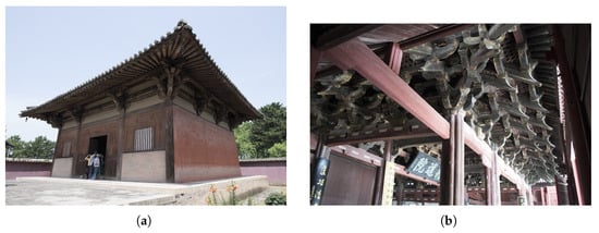
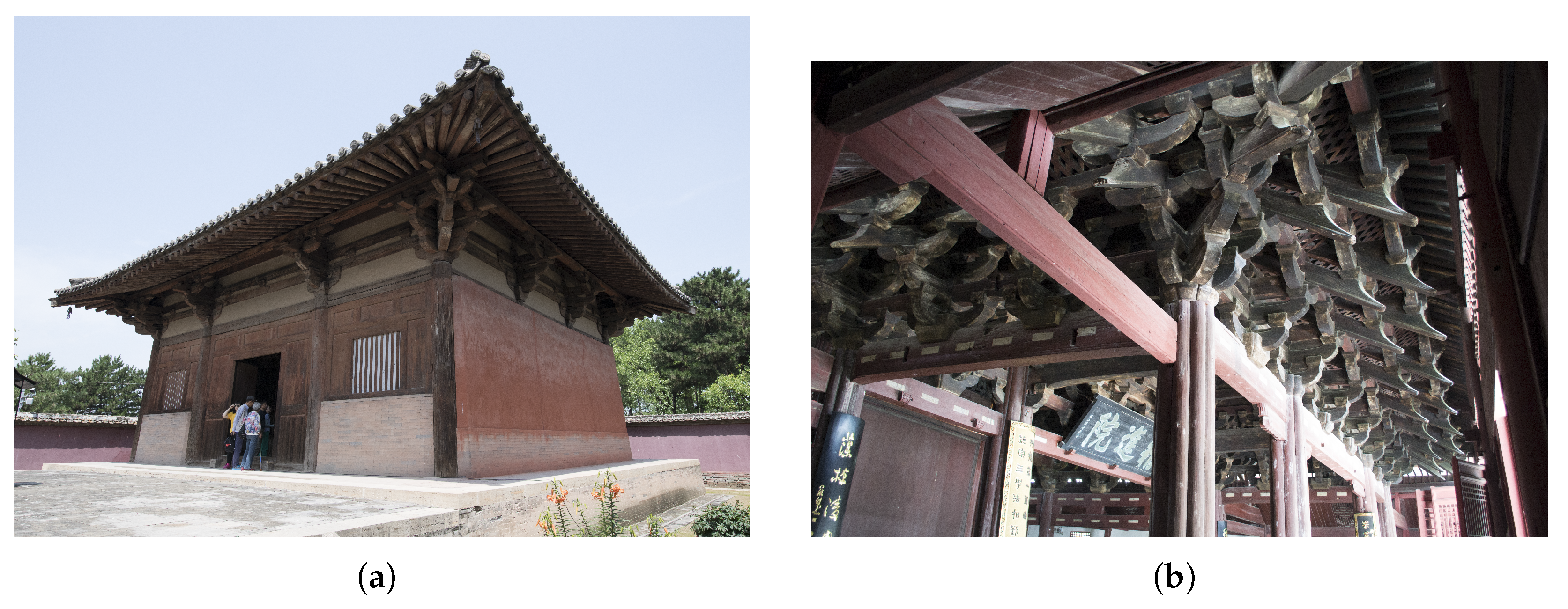
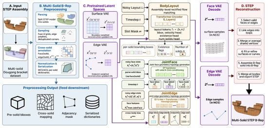
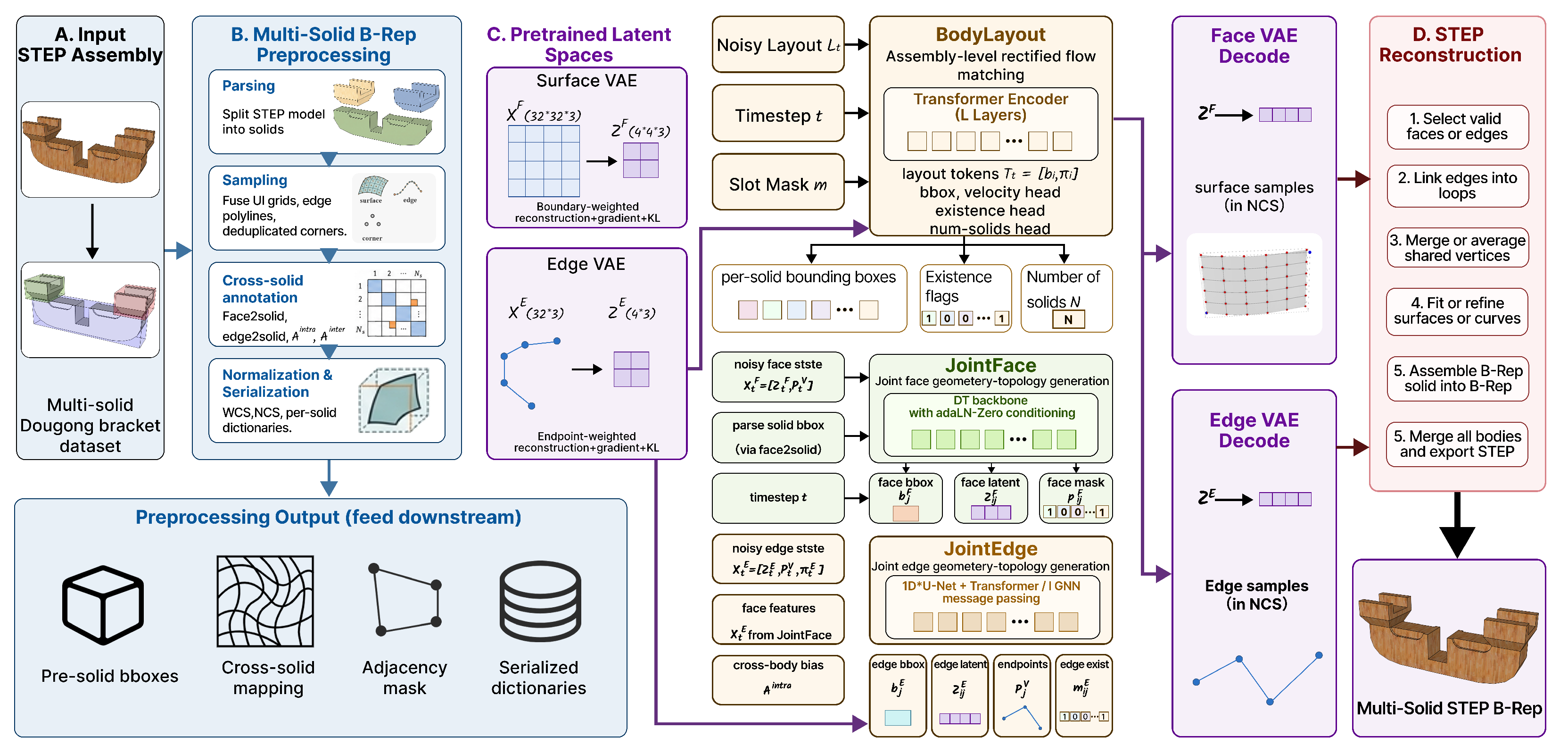
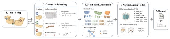
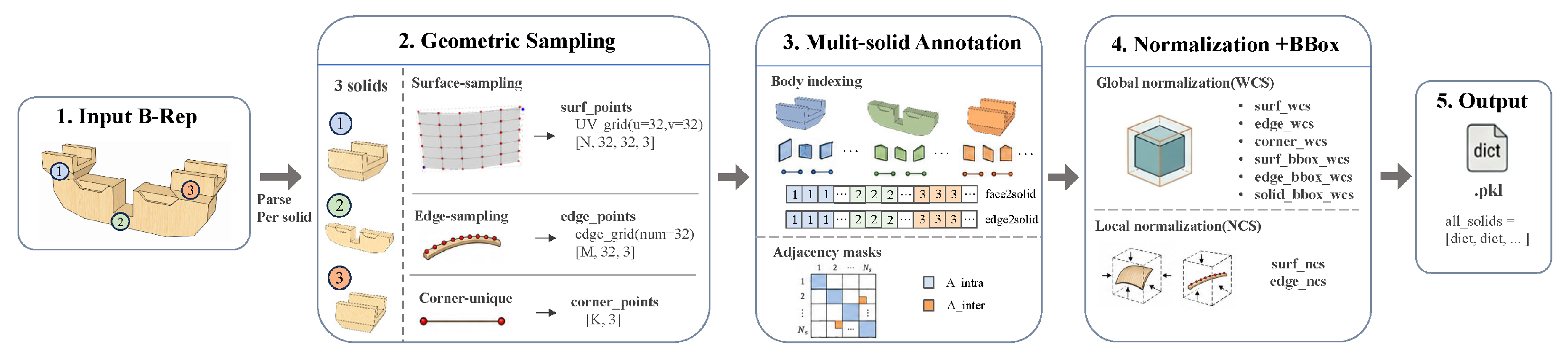
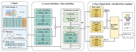
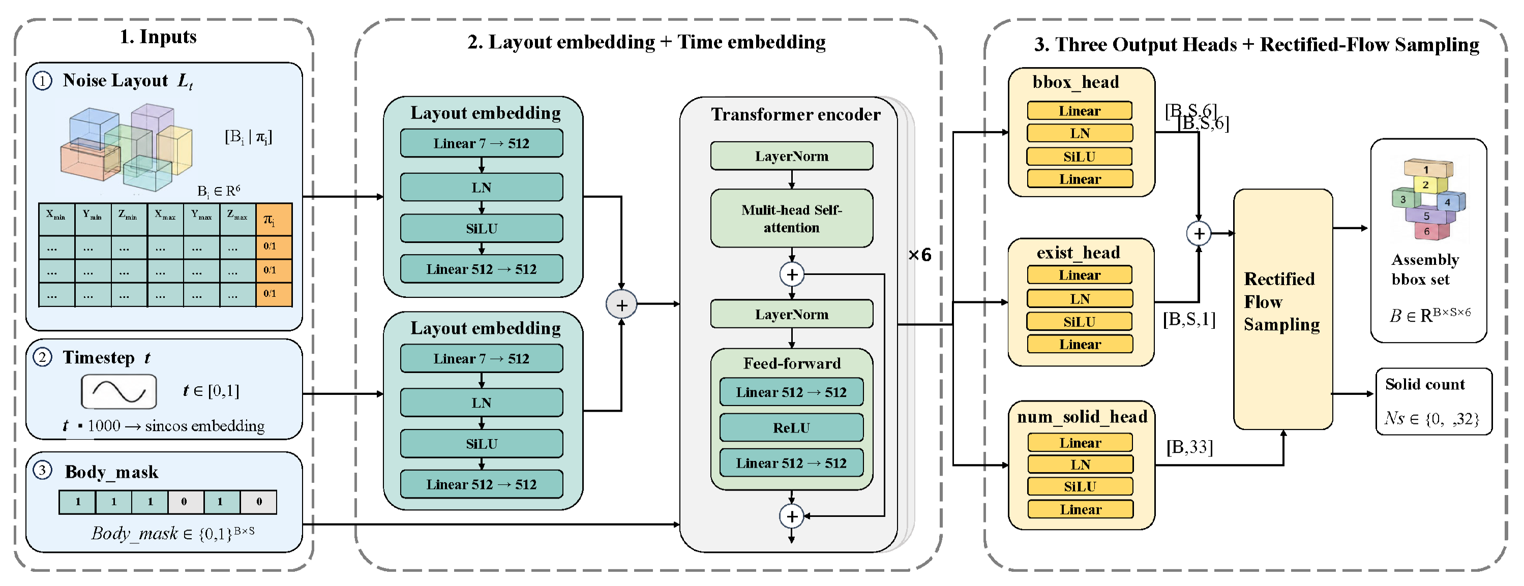
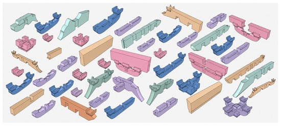
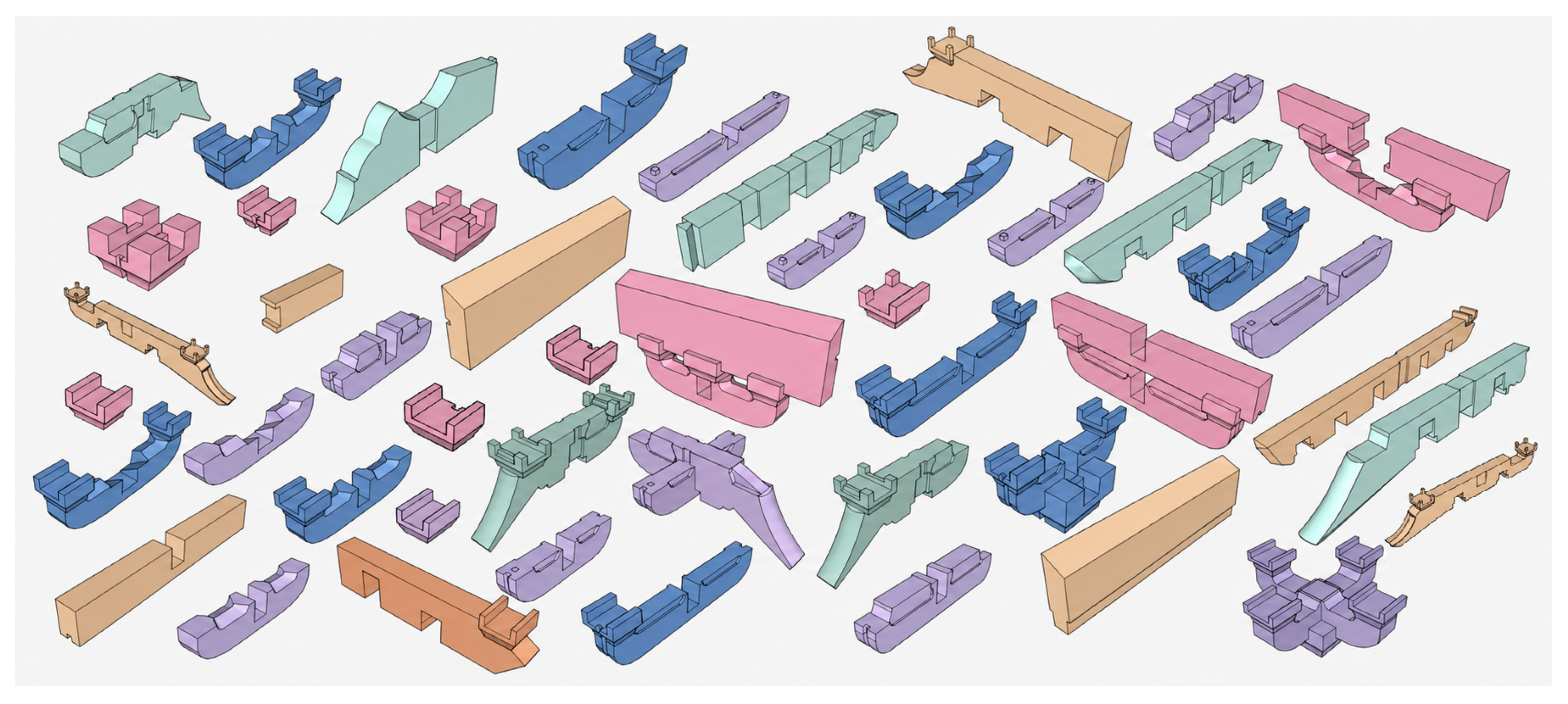
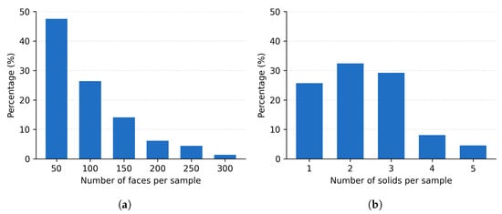
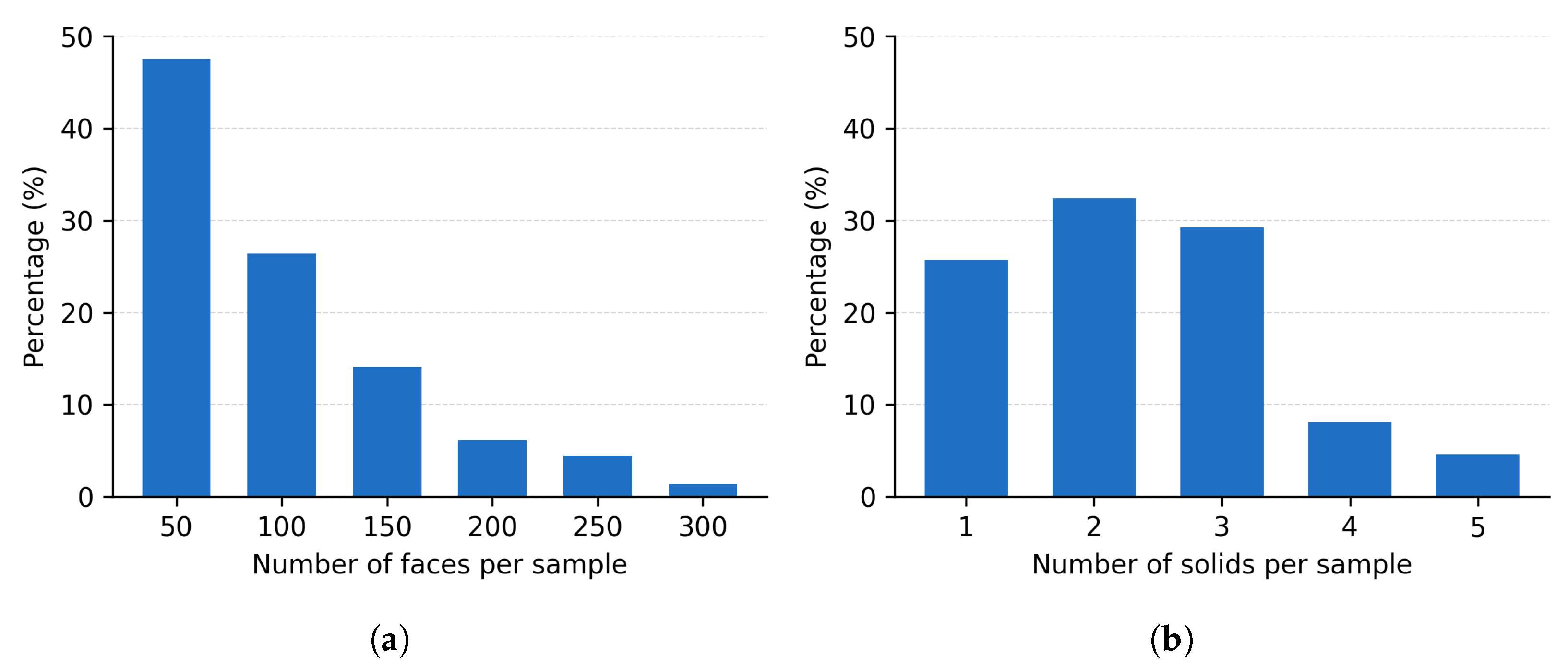
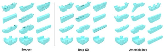
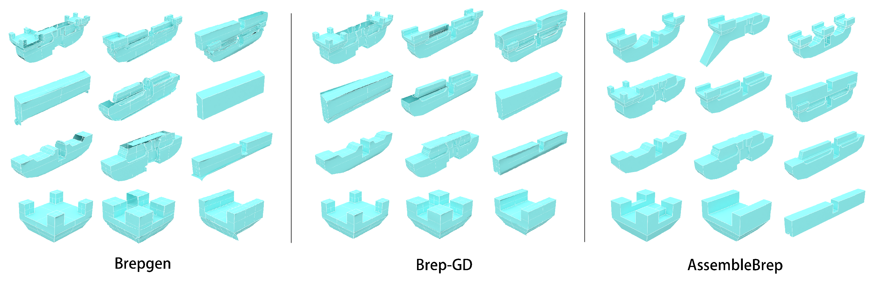
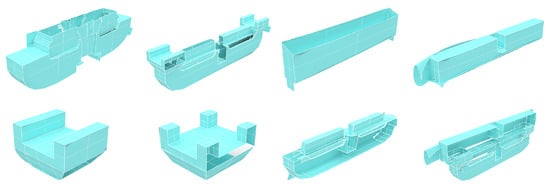
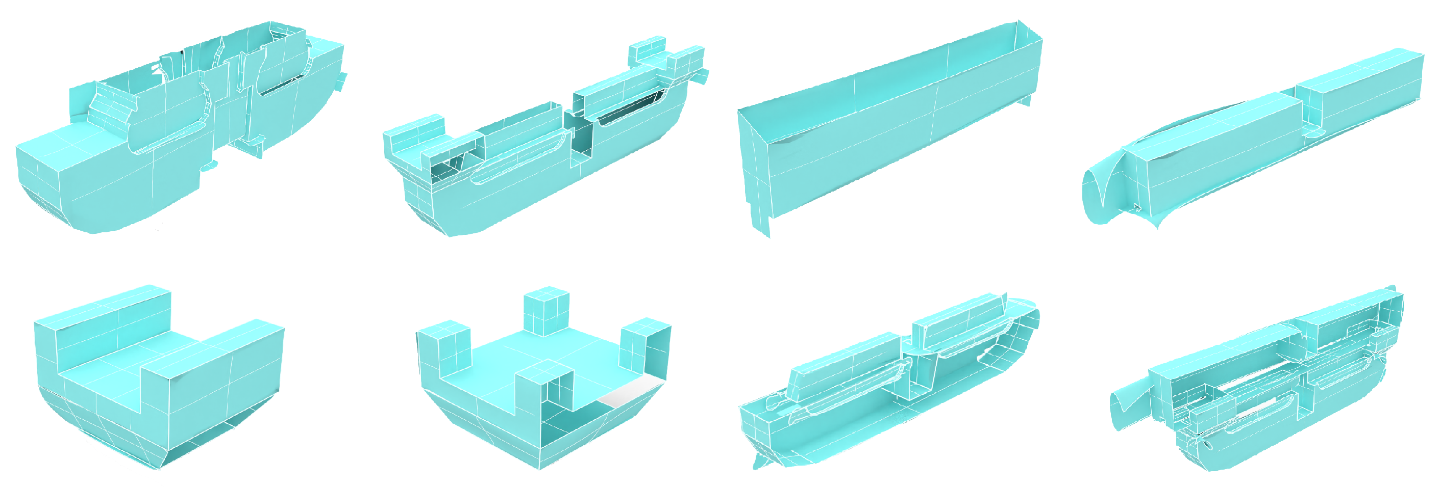

Disclaimer/Publisher’s Note: The statements, opinions and data contained in all publications are solely those of the individual author(s) and contributor(s) and not of MDPI and/or the editor(s). MDPI and/or the editor(s) disclaim responsibility for any injury to people or property resulting from any ideas, methods, instructions or products referred to in the content. |
© 2026 by the authors. Licensee MDPI, Basel, Switzerland. This article is an open access article distributed under the terms and conditions of the Creative Commons Attribution (CC BY) license.