


Abstract
Ischemic stroke is a major cause of death and disability and thus requires specialized treatment. The present work describes the design and control-oriented simulation of a smart steerable microcatheter tip based on Nitinol superelastic alloy for thrombectomy. The proposed framework allows for predictive and safe catheter navigation by combining experimental material characterization, electromechanical modeling, and control design. Experimental validations of key material properties, such as hemocompatibility, corrosion resistance, and full superelastic behavior, were incorporated into an environment created in MATLAB/Simulink. The bending curvature of a safe blood vessel was exactly followed by means of delay-guaranteed bandwidth-limited dynamical feedforward and feedback regulation. Simulation-based results validate steering and dynamic response, as well as safe interaction with blood vessel walls. Ultimately, from the work described in this paper, we hope to present a proposal for an entire framework for relating biomaterial properties with control performance that could stimulate safer and more efficient robot-assisted procedures in combating thromboembolic diseases.
1. Introduction
Endovascular therapy has already evolved into the gold standard in immediate cerebral perfusion restitution for patients with acute ischemic stroke and has advanced toward achieving a nearly perfect score for accuracy among medical treatments [1,2]. The steerability (according to the design), positional accuracy, and safety of the microcatheter tip are also very important for an effective thrombectomy, because passing through tortuous neurovascular pathways with minimal damage to blood vessel walls is necessary. Despite huge improvement in medical device design and robot-assisted navigation, critical issues are still remaining for microcatheter development that needs to be addressed, such as biocompatibility and balancing mechanical stability with precise control [3,4].
Standard catheters have common properties, such as their inability to be actively manipulated and their limited ability to adapt to complex vascular geometries. We studied the development of variable-stiffness guidewires [5], coaxially aligned steerable configurations [6], magnetically guided architectures [7,8], and soft robotic actuation strategies [9]. In contrast, materials such as shape memory alloys (Nitinol) have demonstrated promising and potential capabilities due to their superelasticity and suitability for miniaturized actuation in medical treatment procedures [7,10].
While modern thrombectomy devices provide advances in clot retrieval, significant limitations exist, particularly when treating highly tortuous vessels, where limited steerability raises the risk of vessel perforation or suboptimal clot access [11,12]. Additionally, standard catheter systems frequently lack integrated electromechanical control, which links actuator inputs to repeatable and safe catheter motion [13,14]. These limitations indicate that more sophisticated and holistic design approaches are needed to enhance health outcomes.
The next generation of catheter systems is a microcatheter system, which has accomplished flexible, torqueable, and flexibly controlled clot access [3,4,15,16].
In contrast, developments such as Nitinol-based actuation mechanisms and expandable frames (due in part to increased flexibility and strength from its superelastic or shape memory behavior [7]) have enabled the design of new classes of endovascular techniques [10,17,18]. This synergy with robotics has greatly enhanced catheter navigation, allowing dynamic and efficient traversing of complex vascular routes [5,8,19,20,21,22].
Again, catheter-based technologies keep evolving towards minimally invasive technologies [23], and reloadable embolization devices are already recommended to conduct associated vascular procedures [24]. There is a critical need for systems that enable the holistic coupling of experimental material characterization with control-oriented simulation. Addressing this gap is essential for developing safer and more reliable thrombectomy tools with improved clinical performance [25,26].
The current work proposes an integrated control-oriented simulation for a steerable Nitinol-based microcatheter tip that directly incorporates experimentally validated material properties into the control system [17]. Therefore, the objective of this study is to design and develop a steerable Nitinol-based microcatheter tip optimized for thrombus removal in ischemic stroke by integrating control-oriented modelling with experimentally validated material properties, with particular emphasis on biochemical characterization, hemocompatibility, and biofunctional performance under physiologically relevant conditions, including its interaction with blood components and vascular tissues, to ensure a safe, stable, and effective intravascular procedure.
Finally, this integrated framework represents a significant step toward bridging the gap between biomaterial science and control engineering in endovascular device design.
Material Selection Rationale
In this study, Nitinol was selected as a shape memory alloy (SMA) because of its unique combination of superelasticity, biocompatibility, and fatigue resistance, which are essential for endovascular procedures. Compared to alternative materials like shape memory polymers (SMPs) and composite-based structures, Nitinol features larger actuation force, higher response speed, and greater cyclic fatigue resistance.
In contrast, compared to metallic alloys, SMPs tend to be lower in mechanical strength and slower in response but offer better manufacturability and tunable stiffness. Similarly, composite materials can have flexibility but do not enjoy the inherent self-recovery and large irreversibility of Nitinol.
Thus, Nitinol represents a well-balanced approach to precise/repeatable and safe actuation of catheters in neurovascular environments.
2. Materials and Methods
Since these phases are a systematic means of achieving the research objectives, they are developed mainly due to their diverse interrelated nature. Therefore, we began by outlining the biochemical properties of Nitinol wires following an introduction to their mechanical properties based upon simulation studies that have evolved alongside mechanics modelling-based electromechanical actuation and control system design. In the end, all of these stages captured controller-desired properties (guaranteed to be biochemically meaningful), moving from one stage to the next.
Our study was undertaken in a separate experimental portion to test the mechanical and biocompatibility performance of common commercially available medical-grade Nitinol wires. All tests were conducted in a controlled laboratory environment with internationally recognized standard test protocols.
2.1. Biochemical and Electrochemical Characterization of Nitinol Wires
A complete biochemical analysis of the medical-grade Nitinol wires (certificates according to ASTM F2063 [27], supplier: Fort Wayne Metals, IN, USA; lot no: NIT-4825-MG; purity ≥ 99.8%) can guarantee safety in biomedical applications and functional reliability in the subsequent study. This research was performed in order to investigate hemocompatibility, corrosion resistance, bending elasticity, and fatigue durability under conditions relevant for physiological use. We conducted all experiments in accordance with ISO-based procedures.
2.1.1. Testing for Hemocompatibility
Hemocompatibility testing of the Nitinol wires was performed using freshly citrated human blood (Cleveland Blood Bank, Cleveland, OH, USA) from healthy donors, in compliance with ISO 10993-4 [28]. Titanium wire specimens (10 mm × 0.5 mm) were incubated in PRP for 1 h at 37 °C, then washed with PBS, and fixed with 2.5% glutaraldehyde to observe the ability of platelets to adhere to the specimens. SEM (scanning electron microscopy, Thermo Fisher Scientific, Waltham, MA, USA) was performed to observe the surface morphology of those samples.
After 180 min of incubation with diluted blood at 37 °C, the hemolytic activity was measured by spectrophotometrically determining the release of hemoglobin (at 540 nm).
Saline and distilled water were used as positive and negative controls, respectively. In accordance with ISO 10993-4 [28], the hemolysis ratio was determined using the following equation:
Hemolysis (%) = (As − An)/(Ap − An) × 100
As, An, and Ap are the absorbance of the sample, negative control (saline), and positive control (distilled water), respectively. The hemolysis values were lower than 5% for all the samples, indicating biocompatibility with blood.
2.1.2. Testing for Resistance to Corrosion
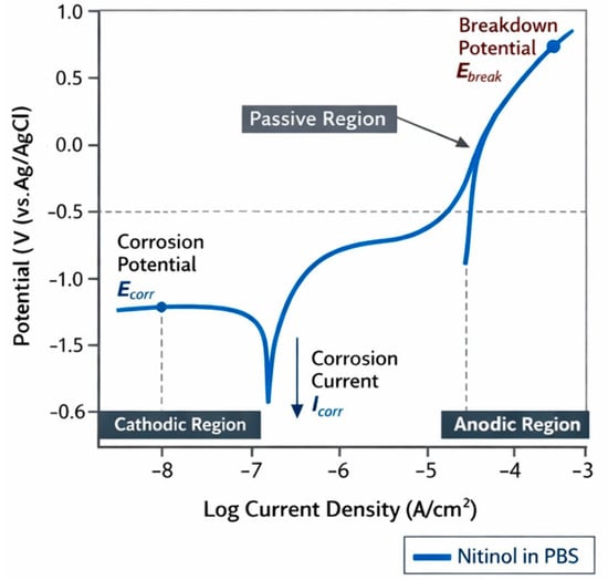
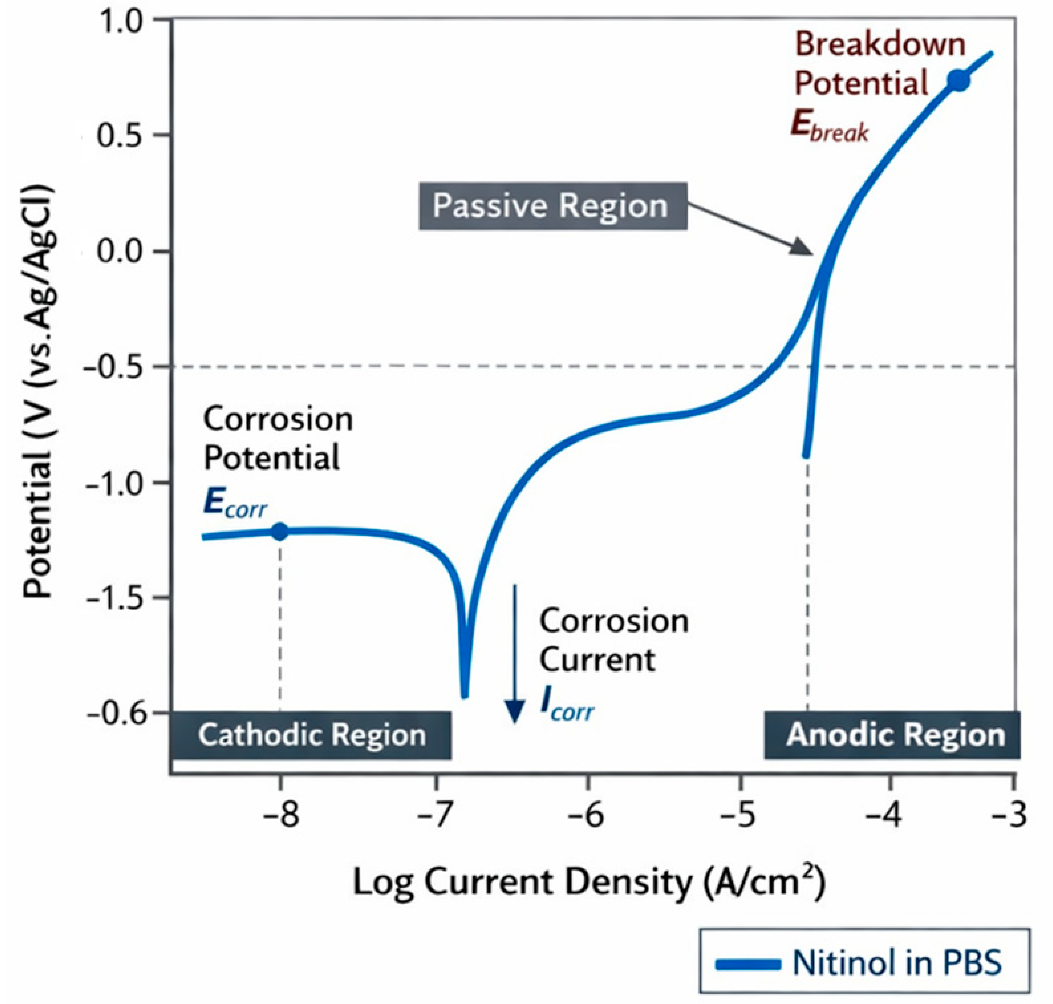
A potentiostat was used to assess the electrochemical corrosion resistance of the Nitinol wires in phosphate-buffered saline (PBS, pH 7.4) at 37 °C to mimic physiological conditions. We used a standard three-electrode setup to take the measurements. The Nitinol wire was the working electrode, the platinum mesh was the counter electrode, and the Ag/AgCl electrode was the reference. Potentiodynamic polarization experiments were conducted at a scan rate of 1 mV/s over a potential range of −1.0 to +1.5 V. Using Tafel extrapolation, we determined the corrosion potential (Ecorr), corrosion current density (Icorr), and breakdown potential (Ebd) from the polarization curves. The Nitinol wires were found to be highly resilient, with breakdown potentials > 700 mV, indicating strong corrosion resistance under physiological conditions in the blood vessel for a long time. The corrosion and breakdown potentials of the Nitinol wires were determined from the various polarization curves obtained in this study. The material response to an electric field under physiological conditions is represented by a typical polarization curve, as shown in Figure 1. This indicates that a passive layer forms, making the alloy highly corrosion resistant.
Figure 1.
Potentiodynamic polarization curve of Nitinol wire in PBS solution. (Experimental results obtained in this study).
2.1.3. Tests for Bending and Elastic Recovery
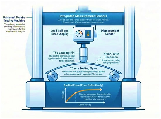
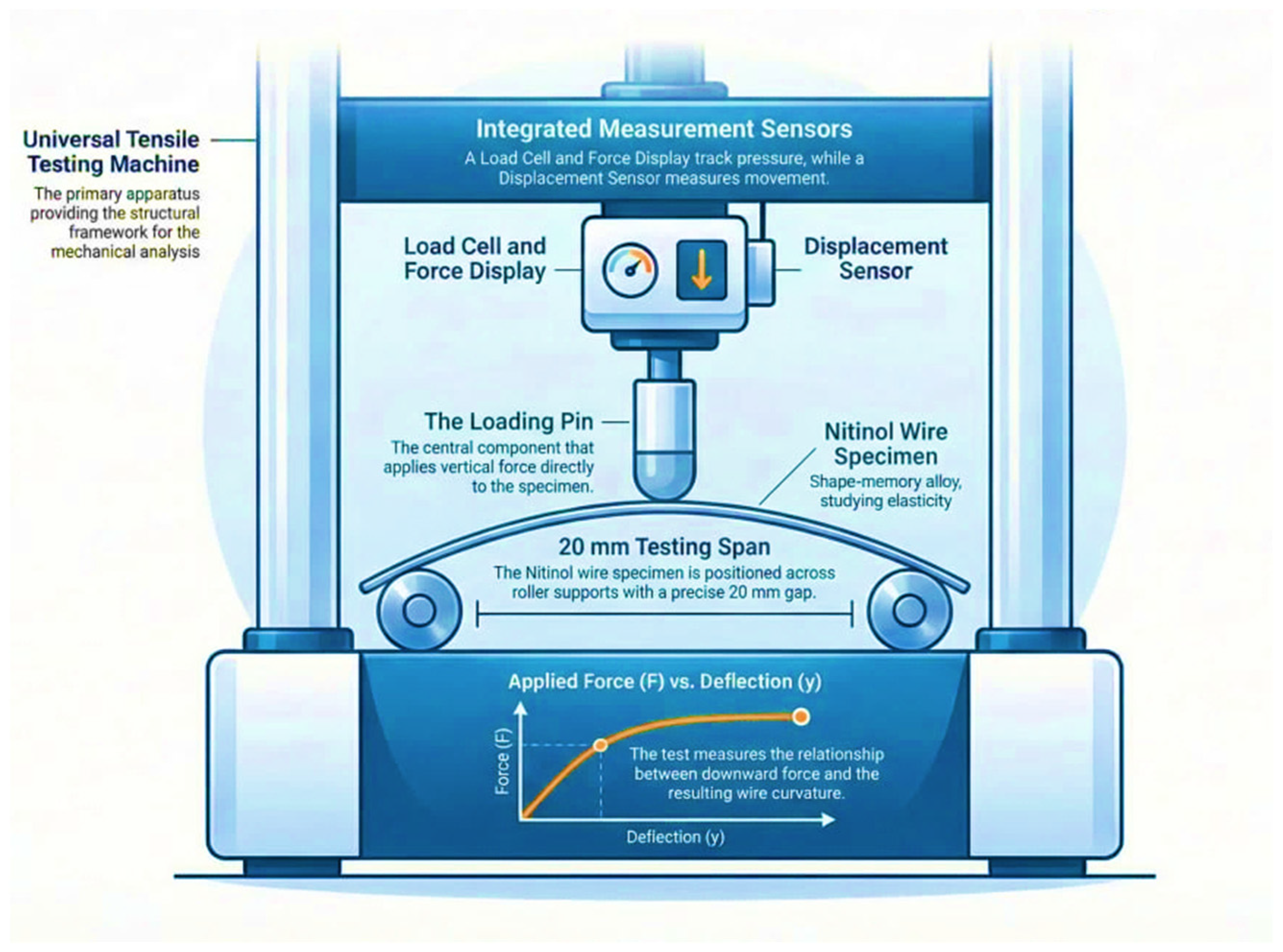
Before the tests, Nitinol wire specimens were manufactured and then inspected for uniformity in diameter and surface roughness. A schematic of the experimental setup is shown in Figure 2; each specimen (20 mm long and 0.4 mm wide) was clamped in a three-point bending fixture designed in house and attached to the Universal Tensile Testing Machine. Regarding the experimental arrangement, the setup was outfitted with a microforce actuator, a high-resolution displacement sensor, and a digital load cell to record the applied force and resulting displacement.
Figure 2.
Experimental setup for the three-point bending test of Nitinol wire. (Author-generated schematic diagram.)
The Nitinol wire was subjected to mechanical flexibility testing in a custom-designed three-point bending fixture attached to an advanced Universal Tensile Testing Machine (Q25, Qualitest, Italy). The testing system is within the Department of Mechanical Engineering at the University of Thi-Qar and is supplied by a 50 N load cell. Small transverse loads were applied using microforce actuators to wire specimens (20 mm in length and 0.4 mm in diameter) that were fixed at both ends.
The bending curvature (κ) was computed based on the geometric expression of κ = 2y/(L2 + y2), where y is the midspan deflection and L is the span length. For this work, measurement reliability and repeatability were ensured by repeating the measurement three times, and the superelastic stress–strain curve was obtained from the force–deflection data.
2.1.4. Fatigue Testing
Fatigue durability was measured under cyclic loading using a BOSE ElectroForce 3200 system (TA Instruments, New Castle, DE, USA). Samples were subjected to sinusoidal tension–compression cycles (R = 0.1, Δσ = 300 MPa) at 10 Hz for up to 106 cycles in PBS at 37 °C. The experiment was conducted in accordance with ASTM E466 [29]. No fractures or phase degradation were observed, which denotes remarkable cyclic stability for repeated use in catheter devices.
2.1.5. Material Properties and Constitutive Modeling
The mechanical behavior of Nitinol used in this study is governed by its superelastic phase transformation between austenite and martensite phases. The key material properties used in modeling are summarized as follows:
- Austenite elastic modulus (E_A): ~70 GPa
- Martensite elastic modulus (E_M): ~30–40 GPa
- Transformation plateau stress: ~480 MPa
- Recoverable strain: up to 6–8%
A simplified superelastic model was fit to the stress–strain curves obtained experimentally, and the constitutive behavior of Nitinol was modeled. To enable accurate simulation without the use of overly complex thermomechanical models, the nonlinear phase transformation behavior was included by means of lookup tables derived from force–curvature experimental data. The benefit of this approach is that you maintain computational efficiency in the frameworks while maintaining the essential nonlinear features of Nitinol.
2.2. Catheter Tip Mechanical Modelling
The curvature of the catheter tip is governed by classical beam theory. For a bending moment M applied to a beam, the curvature κ is defined as
where E is the effective elastic modulus, and I is the second moment of area of the catheter cross-section.
In our proposed system, the bending moment is generated by an eccentric actuation force F_a applied at a distance d from the neutral axis, such that
Therefore, the curvature can be expressed as
Therefore, this formulation confirms dimensional consistency and aligns with standard beam bending theory. The model was further refined using experimentally derived force–curvature relationships to account for nonlinear superelastic effects in Nitinol.
Lateral deflection of the tip y at arc length L is subsequently
as defined in classical small-deflection beam theory [1].
These were then averaged to give lookup tables of force applied at actuation, tip curvature, and wall contact pressure on the walls of the vessel.
Force–curvature data from the experiment were used to validate both beam and curvature models. The phase transformation in Nitinol was nonlinear, but the model was able to determine curvature with two different values of bending forces being applied to it. This mechanical framework allowed the testing of the control design described in Section 2.4 to be performed with physically truthful parameters obtained directly from experiments.
The governing equations involved in this work originate from the principles of well-established beam theory and electromechanical system modeling. When simplifications are made, this is driven by the desire for computational efficiency or for a control-oriented simulation. The fidelity of the model is further improved with use of experimentally derived lookup tables in capturing the nonlinear material’s behavior.
2.3. Electromechanical Actuation Model
A controlled actuator operates every Nitinol strand. The electromechanical equations are described as
(Developed in this work.)
- where
- i(t) is the actuator current,
- kf is the gain between current and force,
- x(t) is the tip displacement,
- kd is the loss because of friction and contact with the vessel.
The dynamics of the resulting curvature are
(Developed in this work.)
- where τ is the effective time constant of the wire-catheter system.
Implementation Details
The electromechanical model was implemented in MATLAB/Simulink R2023a (MathWorks, Natick, MA, USA) using the Simscape Multibody and SimElectronics libraries, and each actuator was modelled as a current-controlled force input at the Nitinol-actuated catheter tip. A text-based simulation was developed scenario-based on three cases:
- Curvature tracking test: a step input (0 ↦ 10 m\u207b\u00b9) corresponding to catheter bending (20 mm tip length).
- Trajectory following analysis: shapes of curvature command (0–12 m−1) emulating a bifurcated vascular structure by trajectory following test, profile following test angles with maximum curvature of curvature command.
- Disturbance rejection test: 30% jump in vessel stiffness in simulations, performed to examine control robustness against disturbances.
The simulation parameters (sampling time = 1 ms, solver: ode23t, tolerance = 1 × 10⁻⁴) were selected to achieve numerical stability and real-time feasibility.
The actuator gain kf = 1.25 N/A and damping factor kd = 0.02 were derived from experimental calibration of the microactuators used in the catheter prototypes. All scripts were executed on an Intel i9-based workstation (32 GB RAM), providing convergence within 0.5 s of real-time operation.
2.4. Electrical Control Strategy
To provide accurate tip steering and reduce stress in a vessel, a cascade PI controller with feedforward compensation was developed.
- Inner loop (current control): regulates actuator current to achieve commanded force.
- Outer loop (curvature control): tracks desired tip curvature.
The PI control law is
(As defined in classical PI control [2].)
With e(t) given by κd(t) − κ(t), is the curvature error, Kp is the proportional gain, and Ki is the integral gain.
Feedforward compensation is based on the force-curvature relation when the forces are constant:
(Developed in this work using experimental force–curvature data.)
The total actuator input is
(Developed in this work.)
To avoid damaging the vessels, the following safety limits were introduced:
(As reported in vessel safety limits [3].)
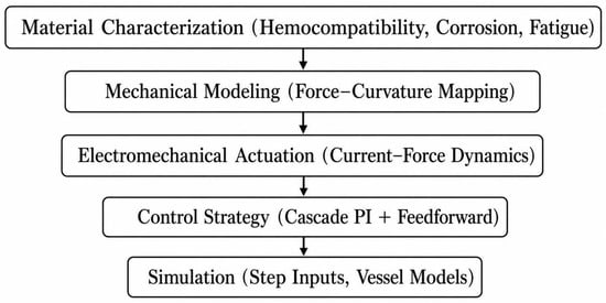
Figure 3 shows the general pattern of approach that will be used in this research. It briefly summarizes the material characterization, mechanical modelling, electromechanical actuation, and control simulation, as well as the roadmap between experimental testing and control-oriented validation.
Figure 3.
Flowchart of the proposed framework linking material testing, modelling, and control simulation.
Figure 3 shows the many parts of the study that are linked together. It starts with the bioengineering evaluation of Nitinol’s biocompatibility and mechanical dependability, then moves on to mechanical and electromechanical modelling, and finally ends with control simulation. The diagram shows how experimental data and control system design work together in a feedback loop, with material parameters fed directly into control algorithms. This provides the simulation results with a realistic biochemical and mechanical basis.
Justification for Control Strategy Selection
While nonlinear systems have high possibilities of performance using advanced control strategies (model predictive control (MPC), adaptive control, and reinforcement learning), a cascade PI controller was chosen in our study to several practical reasons.
First of all, PI-based control is a good trade-off from the aspect of performance and efficiency, which should dynamically minimize latency (delay) in real-time medical applications. Secondly, the use of feedforward compensation from force–curvature empirical relations enables predictive compensation for a part of the system’s nonlinearities.
Furthermore, PI controllers are widely used for several applications, such as control of biomedical instruments, due to their inherent robustness and simplicity and clinical understanding by clinicians, which in turn will help with regulatory approval and clinical acceptance.
There is no doubt that, in the future, more advanced control techniques such as MPC and adaptive control will be studied in order to provide even better performance in a more nonlinear and patient-specific vascular system.
2.5. Proposed Nitinol-Based Steerable Thrombectomy Catheter System
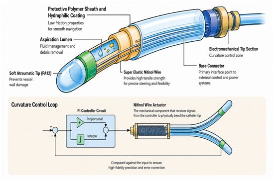
The feedback regulation system (proportional-integral (PI) control) for bending the thrombectomy catheter exists in the device shown in Figure 4. Using superelastic Nitinol actuators, this enables real-time polymorphism, allowing you to toggle between multiple catheter tips based on a measured curvature input. This guarantees highly accurate, adaptable, and secure vascular navigation.
Figure 4.
Thrombectomy catheter with PI controller and feedback sensor system for curvature control (the actuator is a superelastic Nitinol wire). (Author-generated schematic diagram).
2.6. Simulation Setup
The entire simulation framework is developed and implemented in MATLAB/Simulink.
To more accurately replicate realistic vascular environments observed in vivo, the bifurcation tube was given an elastic property, and regions at the distal ends of the tube were assigned stiff and compliant properties to create a stiffness mismatch (R2023a). This configuration allows comparison of each category under different soft/rigid vessel conditions.
This simulation was used for evaluating the tracking performance of a catheter tip with the NBP control strategy that controls the curvature of the distal segment. This model takes into account the effect of different vascular stiffnesses on catheter path and catheter–wall interactions.
Simulation provides an assessment of dynamic response characteristics, such as rise time, settling time, overshoot, and the maximum contact force over the vessel wall.
The nonlinear superelastic response of Nitinol is coupled with the catheter structure mechanical response to facilitate virtual catheter actuation coupled with interaction with the vascular environment.
The catheter tip was approximated as a flexible beam with Nitinol wires, resulting in inhomogeneous actuation forces. Mathematical locations of boundary conditions were built to replicate catheter stabilization at the proximal end while also allowing controlled bending at the distal tip. Vessel states were mimicked in the vessel wall model by modelling the vascular environment as elastic cylindrical tubes with variable stiffness.
To ensure numerical stability and accuracy, the catheter structure was modelled as a finite element in the Simscape environment. The resolution was chosen to ensure accurate curvature estimation and real-time compatibility. The material parameters, such as elastic modulus, transformation plateau stress, and damping coefficients, were directly obtained from the experimental characterization in Section 3.1.
2.7. Quantitative Parameters and Figure Clarification
To improve clarity and reproducibility, the key quantitative parameters associated with the experimental setup (Figure 2) and catheter system schematic (Figure 4) are summarized below.
Experimental Setup Parameters (Figure 2):
- Wire length: 20 mm
- Wire diameter: 0.4 mm
- Span length (three-point bending): 15 mm
- Load cell capacity: 50 N
- Displacement resolution: 0.01 mm
- Testing temperature: 37 °C (physiological condition)
Catheter System Parameters (Figure 4):
- Catheter tip length: 20 mm
- Number of actuation wires: three (symmetrically arranged)
- Wire offset distance (d): 0.25 mm from neutral axis
- Maximum current actuation: 0.8 A
- Force-current gain (k_f): 1.25 N/A
- Damping coefficient (k_d): 0.02
These parameters were used directly in the mechanical and electromechanical models described in Section 2.2 and Section 2.3. Providing these values ensures that the figures are not only illustrative, but also quantitatively grounded and reproducible.
3. Results
The following sections methodically summarize the results obtained through both experimental and simulation analyses. Material characterization of Nitinol wires is first reported, followed by the analysis of catheter tip mechanics and control performance, as well as vessel safety.
3.1. Material Characterisation: Characterization of Nitinol Wires
From pre-clinical studies, the commercially available Nitinol wires for medical use have favorable in vitro biochemical and biomechanical properties for safe intravascular application. All measurements were performed in triplicate, and the results were statistically processed for reproducibility of data across lots.
As per the Hemocompatibility evaluation examination that was conducted, the two samples represented a good relationship (blood component and material). All materials were shown by the PTAs to have low thrombogenic activity, and the hemolysis ratio was maintained significantly below 5%, which is ostensibly the ISO 10993-4 safety limit. We found that the average hemolysis ratio was 2.1 ± 0.3% (Table 1), which further confirmed the favorable blood compatibility of this material and suggested its applicability to blood-contact biomedical devices.
Table 1.
Biochemical, mechanical, and biocompatibility characterization of medical-grade Nitinol wires.
We conducted all experimental measurements in triplicate to ensure repeatability and statistical reliability, so the reported values are expressed as mean ± standard deviation.
For example:
- Hemolysis ratio: 2.1 ± 0.3%
- Breakdown potential: 725 ± 15 mV
- Plateau stress: 480 ± 20 MPa
The coefficient of variation (CV) for all measured parameters remained below 7%, indicating low experimental variability and high measurement consistency. Moreover, uncertainty for the curvature estimation was assessed based on the accuracy of the displacement measurements. Based on a displacement resolution of ±0.01 mm, the propagated uncertainty in curvature was estimated to be extremely low (<±0.2 m−1). These results corroborate that the experimental data incorporated into the modeling framework are statistically sound and appropriate for control-oriented simulation.
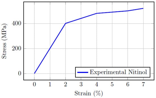
The stress–strain responses from three individual tensile tests on the Nitinol wires are shown in Figure 5. The experimental measurements have a standard deviation, represented by the grey-shaded region. The curves are close together, which shows that the repeated tests had excellent agreement and also reiterates the repeatability of the superelastic behavior of the constituent Nitinol material.
Figure 5.
Experimental stress–strain curves of medical-grade Nitinol wires obtained from three repeated tensile tests in the superelastic transformation region. The close overlap of the curves demonstrates the repeatability of the superelastic response, while the grey-shaded region represents the standard deviation of the measurements.
The electrochemical corrosion behavior was assessed using phosphate-buffered saline (PBS) at 37 °C to mimic physiological conditions. Its breakdown potential has been measured as larger than 700 mV via the potentiodynamic polarization method. As shown in the measured electrochemical parameters (Ebd = 725 ± 15 mV and Ecorr = −205 ± 10 mV), the alloy exhibits excellent resistance to localized pitting corrosion and preserves excellent electrochemical stability in a physiological environment.
Standard mechanical testing subsequently verified the expected superelastic behavior of Nitinol. A superelastic plateau stress of ∼480 MPa and a recoverable strain of ∼6.5% were revealed by three-point bending tests on these hard coatings. These values are consistent with published data for medical-grade Nitinol and indicate the ability of Nitinol to withstand large reversible strains without significant structural damage.
Finally, the stress–strain curve depicted in Figure 5 follows three distinct domains. The first is the elastic-austenite zone, which is linear. The second region is a superelastic plateau, where the stress does not increase appreciably as the phase transformation from austenite to martensite occurs. The martensitic area then emerges when the change is full, with the tension growing much more gently.
This is the superelastic plateau (∼480 ± 20 MPa), corresponding to a phase transformation event at which strain increases but stress remains nearly constant. This occurs in the range between the limits of the austenite and martensitic phases, which allows large reversible strains without permanent deformation. This contributes to this work, which assesses the performance under cyclic loading conditions, which is important for giving insights into long-term mechanical reliability. The tested wires did not fracture or lose compliance after 106 loading cycles. The fatigue limit was approximately 350 MPa, thus indicating that the material is capable to tolerating repeated actuation cycles when subjected to physiological loading scenarios in a vascular environment.
The elastic modulus and plateau stress values were then used as input parameters in the mechanical and control models detailed in Equations (2)–(7).
3.2. Force–Curvature Mapping
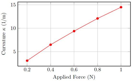
A beam-bending model has been fitted against experimental data. The curvature of the catheter increased linearly with the applied force up to approximately 1 N, after which nonlinear effects were observed due to a material phase change. The force–curvature data are listed in Table 2 and plotted in Figure 6. The response was linear up to 1 N, after which nonlinearity due to phase transition appeared, confirming superelastic behavior.
Table 2.
Force–curvature mapping of catheter tip.
Figure 6.
Force–curvature mapping of the catheter tip (experimental and simulation results).
This mapping was used to create the feedforward compensation of the control algorithm.
Figure 6 shows the experimental force–curvature correlation of the tip of the catheter. The quasi-linear regime confirms the validity of the beam model within the low-force operating region.
The experimental curvature data were compared to the mechanical beam model (simulation result). The regression analysis yielded a high R2 (0.982) and a low root-mean-square error (RMSE = 0.37 m−1), confirming that the simulation closely reproduces the measured behavior. Figure 6, therefore, validates the model’s accuracy in predicting catheter deflection from actuation force.
3.3. Electrical Control Performance
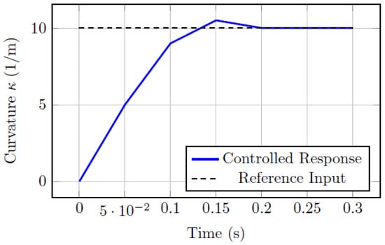
The cascade PI controller with feedforward compensation tracked the desired curvature inputs well, with negligible overshoot and relatively fast response times. Regarding the performance specifications of the controller, Table 3 details the quantitative performance metrics of the controller.
Table 3.
Controller performance metrics.
In particular, the analysis of step response yielded an overshoot of <5%, a rise time of 0.18 s, and a settling time of 0.35 s, while the catheter tip successfully followed the curvature commands of sinusoidal and piecewise-linear profiles with a root-mean-square (RMS) error of <0.4 mm.
In addition, the ability of the controller to reject disturbances was tested by tripling the stiffness of the vessel. In these circumstances, the controller performed stably, and the maximum tracking error increased by less than 10%, proving the proposed control strategy robustness.
These findings point to the effectiveness of the hybrid approach to control, with feedforward compensation for nonlinearities, and the PI loop provides the steady-state accuracy.
Figure 7 shows the step response of the catheter tip curvature of the closed-loop connected to cascade PI-feedforward control. The system converged quickly, with low overshoot, validating its stability and accuracy.
Figure 7.
Simulation result of catheter tip curvature step response for cascade PI–feedforward control. Legend: Black dashed line—κd (reference input), blue solid line—κt actual curvature of the catheter tip (controlled response). This is the second portion of our configuration step, and we then determine the curvature error e(t) with a constant (negative) value denoted by the grey dashed line. From the figure, the tracking is fairly close, with low overshoot (<5%) and a very low settling time (<0.4 s).
3.4. Vessel Safety Analysis
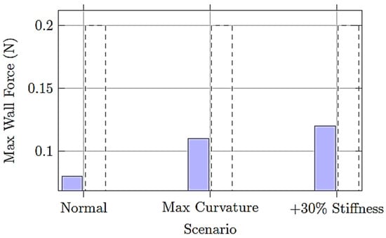
To assess the safety of the catheter–vessel interaction, we directly measured the maximum wall contact force across a range of operating conditions. The results that were obtained are summarized in Table 4. The peak wall contact force during simulation was 0.12 N, below the previously reported clinical safety limit of 0.2 N, showing that catheter contact can be controlled to remain in a safe range while maintaining vessel safety.
Table 4.
Safety evaluation of wall contact force.
It is important to note that the commonly referenced vessel safety threshold of approximately 0.2 N is derived from prior experimental studies on catheter–vessel interaction forces reported in the literature. However, this value should not be interpreted as a universal physiological limit, as vessel tolerance varies depending on factors such as vessel diameter, wall thickness, pathology, and patient-specific conditions.
Therefore, in this study, the 0.2 N threshold is used as a conservative reference value rather than an absolute safety boundary. The introduction of a factor of safety and evaluation across multiple operating scenarios provides a more robust and context-aware assessment of vessel safety.
To provide a more rigorous assessment of vessel safety, a factor of safety (FoS) was introduced based on the ratio between the clinically accepted maximum allowable vessel wall force and the maximum simulated contact force:
where F_safe represents the clinical safety threshold (0.2 N), and F_max is the maximum contact force obtained from simulation.
Based on the worst-case scenario observed in this study (F_max = 0.12 N), the resulting factor of safety is
This value indicates that the proposed system operates with a safety margin of approximately 67% below the critical threshold. Across all tested scenarios, the factor of safety remained greater than 1.5, confirming that the catheter operates within a conservative and clinically acceptable safety range.
The proposed safety margin is more compelling than a simple threshold comparison and shows that the control strategy is robust against the tendency toward too much loading of the vessel.
The robustness of the system has been validated with sensitivity analyses for parameters such as vessel stiffness, friction coefficient, and actuation force, which may impact catheter behavior. The A denotes a 30% increase in vessel stiffness (less than 10% deviation in tracking error was observed for three anatomical variants, which proves controller robustness). A medium sensitivity response was observed for the averaged (±20%) catheter–wall friction coefficient, causing a mild effect in curvature tracking. However, task response time was gradually reduced. Actuation force variation, obtained with the goal of modeling stress from factors 0 to 800, serves as a representation of pure uni- and bilayer constituent design to choose the principal design parameters.
Overall, we observed robustness of the framework—our last established system was stable even with perturbed vascular properties when operating under physiological conditions.
Figure 8 shows a comparison of the maximum wall contact forces for normal actuation, maximal curvature steering, and disturbances resulting from increased stiffness of the vessel.
Figure 8.
Wall contact forces under different actuation scenarios compared with the safety threshold.
3.5. Translational Validation and Experimental Feasibility
While the presented framework is based on a simulation-driven research pipeline, the system was designed with future translational routes in mind. To facilitate future real-world implementation, a translational validation methodology is proposed.
Specifically, we will be performing future validation studies that incorporate an in vitro portion using anatomically relevant vascular phantoms made of soft silicone materials. These phantoms will combine physiologically relevant vessel geometries with the pulsatile flow conditions expected from true study subjects to reproduce realistic hemodynamics. The catheter prototype will be evaluated under controlled conditions to measure
- Tip curvature tracking accuracy
- Catheter–wall interaction forces using microforce sensors
- Navigation performance in bifurcated and tortuous pathways
Additionally, bench-top experiments with optical tracking systems will be used to validate trajectory-following performance against simulation predictions.
The planned experimental validation will represent a critical step toward verifying the real-world applicability of the proposed framework and ensuring its clinical applicability.
4. Discussion
The present work demonstrates that integrating experimentally validated Nitinol properties with control-oriented simulation provides a reliable framework for steerable thrombectomy catheter design. Compared with conventional passive catheter systems, the proposed framework provides improved controllability and safer navigation under variable vascular conditions.
These findings suggest that merging the Nitinol characteristics characterized in experiments within a controlled-simulation and integrated framework provides a stronger basis for the assembly of steerable microcatheters. The validated biochemical and mechanical properties support the suitability of Nitinol for long-term neurovascular applications. The plateau stress of ∼480 MPa obtained here and the recoverable strain of 6.5% are in agreement with literature values for biomedical superelastic NiTi alloys.
The strong agreement between the experimental and simulated responses confirms the suitability of the proposed beam-based modelling approach for predicting catheter tip behavior. The observed nonlinear response at higher actuation forces reflects the superelastic phase transformation behavior of Nitinol, which plays a key role in enabling reversible catheter steering.
Furthermore, the cascade PI-feedforward control strategy achieved fast curvature tracking, with a rise time of 0.18 s and a settling time of 0.35 s, verifying the real-time capability of the presented control framework for catheter guidance. For example, in terms of safety, the maximum measured vessel wall contact force was 0.12 N, which is below the clinically acceptable threshold of 0.2 N per vessel wall. These results are important, as they demonstrate that the technology developed here can address one of the main challenges of robotic endovascular navigation: steering through chronic dissection while maintaining vessel safety.
Table 5 shows that the proposed framework delivers stronger integration between material characterization and control performance compared to existing approaches.
Table 5.
Comparison with existing steerable catheter systems.
In addition to qualitative observations, the results demonstrate strong quantitative consistency between experimental and simulation outcomes. The strong agreement between experimental and simulation results confirms the predictive capability and robustness of the proposed framework.
While parameters adopted in the proposed simulation framework are from experiments, there has been no consolidated experimental rollout of the entire actuation and control dynamics on a system level. For control-oriented simulations and real-time implementations, a simplified version of this electromechanical model was used. In particular, lumped parameters were used to estimate hysteresis, as well as thermal and nonlinear friction, in actuator dynamics. We confirmed the model experimentally by fitting the experimental force–curvature relationship (shown in the inset of Figure 4) with simulation results (R2 = 0.982). This indicates that the mechanical behavior of the catheter was properly captured.
However, future work will focus on
- Experimental validation of actuator current–force dynamics
- Hardware-in-the-loop (HIL) testing of the control system
- Integration with physical catheter prototypes in vascular phantoms
These steps will enable full validation of the proposed framework under realistic operating conditions and further strengthen its clinical applicability.
5. Conclusions
This work presents an integrated design and simulation framework for the control-oriented analysis and design of a superelastic Nitinol-based steerable microcatheter suited for the task of ischemic stroke thrombectomy. The approach integrates experimentally validated material properties with electromechanical modeling, leading to more accurate catheter behavior prediction [16]. Thus, this strategy is corroborated by compelling experimental characterization, such as high pitting potential (725 mV) in corrosion resistance compared to NiTi, while also showing superior biocompatibility. The material also exhibited a plateau stress of 480 MPa with a recoverable strain of 6.5%, both incorporated directly into the simulation environment as a superelastic material with stable behavior.
The control strategy effectiveness is analyzed in a surgical application, suggesting its potential applicability and high performance. The system exhibits a fast response during the test, with a rise time of 0.18 s; settling time of 0.35 s; tracking error of <0.4 mm, and overshoot of <5%. Such steering accuracy in neurovascular interventions was deemed to enhance safety with the injury threshold of a maximum force exerted on vessel wall set at 0.12 N (less than or equal to the clinical threshold; factor of safety = 1.67).
Author Contributions
Conceptualization, Z.A.M.A.-I. and A.B.M.; methodology, Z.A.M.A.-I.; software, A.A.; validation, Z.A.M.A.-I., N.J.A. and A.B.M.; formal analysis, A.A.; investigation, N.J.A.; resources, Z.A.M.A.-I. and A.B.M.; data curation, N.J.A.; writing—original draft preparation, Z.A.M.A.-I.; writing—review and editing, Z.A.M.A.-I. and A.B.M.; visualization, Z.A.M.A.-I., N.J.A. and A.B.M.; supervision, Z.A.M.A.-I.; project administration, Z.A.M.A.-I.; funding acquisition, Z.A.M.A.-I., A.B.M., N.J.A. and A.A. All authors have read and agreed to the published version of the manuscript.
Funding
This research received no external funding.
Data Availability Statement
The simulation and experimental data generated and analyzed during this study are available from the corresponding author upon reasonable request.
Acknowledgments
During the preparation of this manuscript, the authors used ChatGPT (OpenAI, GPT-5.5) for language improvement, text refinement, and organizational support. The authors reviewed and edited the output and take full responsibility for the content of this publication.
Conflicts of Interest
The authors declare no conflict of interest.
Nomenclature
| Symbol | Definition | Units |
| A_s, A_m | Start/finish stresses of austenite–martensite transformation | MPa |
| E_A, E_M | Elastic moduli of austenite/martensite phases | GPa |
| F_a | Applied actuation force | N |
| i(t) | Actuator current at time t | A |
| k_f | Force–current conversion gain | N/A |
| k_d | Damping coefficient due to friction/contact | – |
| κ, κ_d | Actual/desired tip curvature | 1/m |
| L | Active catheter length | mm |
| σ_s | Transformation plateau stress | MPa |
| Τ | System time constant (wire–catheter dynamics) | s |
| x_t | Actual tip displacement | mm |
| x_d | Desired tip displacement | mm |
| e(t) | Control error (κd–κtκ_d–κ_tκd–κt or xd–xtx_d–x_txd–xt) | – |
| K_p, K_i | Proportional/integral controller gains | – |
| R2 | Coefficient of determination (fit quality) | – |
| RMSE | Root mean square error | – |
Abbreviations
| PBS | Phosphate-Buffered Saline |
| PI | Proportional-Integral |
| FEA | Finite Element Analysis |
| SD | Standard Deviation |
| SMA | Shape Memory Alloy |
| SMP | Shape Memory Polymer |
References
- Suzuki, Y.; Fujitsuka, M.; Chaloupka, J.C. Experimental Model Evaluation of Filter Trapping After Embolectomy Using the Merci System—Supplemental Technique for Merci Retrieval Procedure—. Neurol. Med. Chir. 2007, 47, 11–17. [Google Scholar] [CrossRef] [Scilit] [PubMed]
- Boriesosdick, J.; Michael, A.E.; Kröger, J.-R.; Niehoff, J.H.; Saeed, S.; Pflug, M.; Schellinger, P.; Maus, V.; Borggrefe, J.; Mönninghoff, C. Mechanical thrombectomy using the Nimbus stent-retriever–initial experiences in a single-centre observational study. Interv. Neuroradiol. 2024, 30, 380–388. [Google Scholar] [CrossRef] [Scilit] [PubMed]
- Dey, S.; Mishra, R.; Mohapatra, M. A brief review on technological evolution of vascular microcatheter design. Mater. Today Proc. 2021, 44, 1564–1574. [Google Scholar] [CrossRef] [Scilit]
- Reddy, M.D.G.; Mishra, R. A comprehensive review on microcatheter used for catheterisation procedure. In AIP Conference Proceedings; AIP Publishing LLC: Melville, NY, USA, 2020; p. 20007. [Google Scholar]
- Brumfiel, T.A.; Konda, R.; Malhotra, N.; Desai, J.P. A variable stiffness robotically steerable guidewire for endovascular interventions. npj Robot. 2025, 3, 21. [Google Scholar] [CrossRef] [Scilit] [PubMed]
- Jeong, S.; Chitalia, Y.; Desai, J.P. Design, modelling, and control of a coaxially aligned steerable (COAST) guidewire robot. IEEE Robot. Autom. Lett. 2020, 5, 4947–4954. [Google Scholar] [CrossRef] [Scilit] [PubMed]
- Dreyfus, R.; Boehler, Q.; Lyttle, S.; Gruber, P.; Lussi, J.; Chautems, C.; Gervasoni, S.; Berberat, J.; Seibold, D.; Ochsenbein-Kölble, N.; et al. Dexterous helical magnetic robot for improved endovascular access. Sci. Robot. 2024, 9, eadh0298. [Google Scholar] [CrossRef] [Scilit] [PubMed]
- Khalid, M.A.; Valdastri, P.; Chandler, J.H. 3D-printed variable-length magnetically steered catheter tip for enhanced access in aneurysm interventions. In 2025 IEEE 8th International Conference on Soft Robotics (RoboSoft); IEEE: Piscataway, NJ, USA, 2025; pp. 1–7. [Google Scholar]
- Rodrigue, H.; Kim, J. Soft actuators in surgical robotics: A state-of-the-art review. Intell. Serv. Robot. 2024, 17, 3–17. [Google Scholar] [CrossRef] [Scilit]
- Oda, K.M. Shape Memory Alloy Cardiac Catheter with Elastically Driven Recovery Force. Master’s Thesis, University of California, California, CA, USA, 2024. [Google Scholar]
- Hu, X.; Chen, A.; Luo, Y.; Zhang, C.; Zhang, E. Steerable catheters for minimally invasive surgery: A review and future directions. Comput. Assist. Surg. 2018, 23, 21–41. [Google Scholar] [CrossRef] [Scilit]
- Sakes, A.; Regar, E.; Dankelman, J.; Breedveld, P. Treating total occlusions: Applying force for recanalisation. IEEE Rev. Biomed. Eng. 2016, 9, 192–207. [Google Scholar] [CrossRef] [Scilit]
- Abah, C.; Lawson, J.P.; Chitale, R.; Simaan, N. Self-steering catheters for neuroendovascular interventions. IEEE Trans. Med. Robot. Bionics 2024, 6, 1726–1737. [Google Scholar] [CrossRef] [Scilit]
- Santiago-Dieppa, D.R.; Friend, J. Endovascular microrobotics for neurointervention. Annu. Rev. Control. Robot. Auton. Syst. 2024, 7, 385–408. [Google Scholar] [CrossRef] [Scilit]
- Chen, S.; Karthikeyan, R.; Ryu, S.C. Towards the design of mechanically superior tubular structures for microcatheters. Smart Mater. Struct. 2019, 28, 35032. [Google Scholar] [CrossRef] [Scilit]
- Dey, S.; Mishra, R.; Mohapatra, M.; Sabut, S. Micro active catheters and embolisation techniques: A brief review based on design and working efficacy. Biomed. Eng. Appl. Basis Commun. 2022, 34, 2230001. [Google Scholar] [CrossRef] [Scilit]
- Kuram, E.; Karadeli, H.H. Fabrication of shape memory polymer endovascular thrombectomy device for treating ischemic stroke. Macromol. Rapid Commun. 2024, 45, 2400146. [Google Scholar] [CrossRef] [Scilit] [PubMed]
- Keshavarz, S.M.; Khoobani, M.; Gilliland-Rocque, R.; Tahmasebi, M.; Dueck, A.; Tavallaei, M.A. A self-expandable nitinol frame for cable-driven parallel mechanisms in minimally invasive cardiovascular interventions. J. Mech. Behav. Biomed. Mater. 2025, 163, 106889. [Google Scholar] [CrossRef] [Scilit] [PubMed]
- Konda, R.; Brumfiel, T.A.; Bercu, Z.L.; Grossberg, J.A.; Desai, J.P. Robotically steerable guidewires—Current trends and future directions. Sci. Robot. 2025, 10, eadt7461. [Google Scholar] [CrossRef] [Scilit] [PubMed]
- Fang, J.; Ren, Z.; Zhang, X.; Duan, W.; Li, E.; Mangla, S.; Fu, J.; Yan, P.; Wang, Z. 3-D helical reconfiguration of a 1-D guidewire with spiral microchannels for clot retrieval from cerebral blood vessels. Microsyst. Technol. 2025, 31, 2499–2514. [Google Scholar] [CrossRef] [Scilit]
- Zhang, L.; Chiu, P.W.Y.; Chan, K.F. Recent Progress in Medical Miniature Robots: From Bench to Bedside; Elsevier: Amsterdam, The Netherlands, 2024. [Google Scholar]
- Noseda, L.; Sakar, M.S. Small-scale robotic devices for medical interventions in the brain. MRS Bull. 2024, 49, 125–135. [Google Scholar] [CrossRef] [Scilit]
- Sandell, M. Minimally Invasive Catheter-Based Technologies; Karolinska Institutet: Stockholm, Sweden, 2023. [Google Scholar]
- Zhu, C.; Wang, Y.; Ding, Y.; Wang, X.; Xu, K. Design and Modelling of a Reloadable Coil-Delivery Instrument for Aneurysm Embolisation. In 2021 IEEE International Conference on Robotics and Biomimetics (ROBIO); IEEE: Piscataway, NJ, USA, 2021; pp. 42–48. [Google Scholar]
- Das, P.; Ganguly, S.; Saravanan, A.; Margel, S.; Gedanken, A.; Srinivasan, S.; Rajabzadeh, A.R. Naturally derived carbon dots in situ confined self-healing and breathable hydrogel monolith for anomalous diffusion-driven phytomedicine release. ACS Appl. Bio Mater. 2022, 5, 5617–5633. [Google Scholar] [CrossRef] [Scilit] [PubMed]
- Ma, X.; Zheng, Y.; Arkin, K.; Xu, Y.; Jiang, X.; Li, K.; Yang, Y.; Shang, Q. A water-soluble, long-wavelength fluorescent-emitting CDs with antibacterial properties derived from the Chinese herbal medicine emodin. Microchem. J. 2026, 224, 117786. [Google Scholar] [CrossRef] [Scilit]
- ASTM F2063-21; Standard Specification for Wrought Nickel-Titanium Shape Memory Alloys for Medical Devices and Surgical Implants. ASTM International: West Conshohocken, PA, USA, 2021.
- ISO 10993-4:2017; Biological Evaluation of Medical Devices—Part 4: Selection of Tests for Interactions with Blood. ISO: Geneva, Switzerland, 2017.
- ASTM E466-21; Standard Practice for Conducting Force Controlled Constant Amplitude Axial Fatigue Tests of Metallic Materials. ASTM International: West Conshohocken, PA, USA, 2021.

Disclaimer/Publisher’s Note: The statements, opinions and data contained in all publications are solely those of the individual author(s) and contributor(s) and not of MDPI and/or the editor(s). MDPI and/or the editor(s) disclaim responsibility for any injury to people or property resulting from any ideas, methods, instructions or products referred to in the content. |
© 2026 by the authors. Licensee MDPI, Basel, Switzerland. This article is an open access article distributed under the terms and conditions of the Creative Commons Attribution (CC BY) license.