


Abstract
Ducted fans are widely used in vehicles with a high engine power per unit swept area, including hovercraft propulsors and vertical take-off aircraft. Computational fluid dynamics (CFD) is a powerful tool for selecting the aerodynamic configuration of new aircraft and engines and for determining their optimal operating conditions. The full Navier–Stokes equations, closed by the Shear Stress Transport (SST) and Spalart-Allmaras (SA) turbulence models, are used to simulate airflow induced by the rotating blades of quadcopter ducted-fan propulsors. Thrust characteristics of the ducted fan are analyzed based on numerical simulations in different flight modes, such as hovering and oblique inflow. Tip clearance and inner-wall effects on thrust and power are reported. For the studied four-blade ducted fan, varying the blade angle of attack from to raises the thrust coefficient from 0.27 to 0.84 and the power coefficient from 0.18 to 0.50. At a constant shaft power of 3750 W, the optimal relative tip clearance for moderately loaded blades is ( angle). For heavily loaded blades ( angle), maximum thrust occurs at zero clearance. However, even at clearance, losses are less than compared to the closed-tip configuration. For technological reasons, a small clearance is generally preferred.
1. Introduction
Reliable operation of unmanned aerial vehicles (UAVs) across the full range of flight modes requires a thorough understanding of the aerodynamics of the airframe and of every propulsion component at the design stage. Of particular importance are the thrust characteristics of the propulsor and the way its slipstream affects the rest of the vehicle [1]. Numerical and experimental investigations consistently show that propeller operation strongly modifies the local force, torque and acoustic field of the aircraft [2,3]. The resulting acoustic signatures are routinely used to identify aircraft of a given class, to recognise their manoeuvres and to extract information for tracking purposes [4,5]. Significant acoustic disturbances can also impose restrictions on the use of UAVs in urban environments due to strict environmental regulations.
Among small-size transport aircraft, multirotor configurations and in particular quadcopters have emerged as compact and manoeuvrable platforms with useful payload-to-mass ratios [6]. Enclosing the rotor inside a profiled duct increases the propeller thrust by up to 40% and reduces the induced losses at the blade tip, which raises the propulsive efficiency and lowers the radiated noise [7]. The thrust augmentation produced by the duct decreases as the freestream velocity grows, so the ducted fan is normally used as a primary propulsor up to flight speeds of about 150–180 km/h. Even so, the ability of a ducted fan to generate large power within a limited swept area makes this configuration attractive for short-take-off and vertical-landing aircraft.
One of the principal tools for optimising the aerodynamic characteristics of new UAVs is high-fidelity numerical simulation of stationary and unsteady flows. Compared with conducting experiments, this approach reduces the cost of the early design stage and supports the search for entirely new airframe and propulsor shapes. Beyond the integral thrust characteristics, simulation also gives access to the detailed flow field generated by the propeller, which in turn enables improvements in aerodynamic performance, flight speed, fuel consumption and stability.
Golovkin et al. [8] developed a method for determining the nonlinear aerodynamic characteristics of a combined load-bearing system under non-stationary conditions. Moizykh et al. [9] reported experimental aerodynamic measurements for a disk-shaped UAV with a rotor-in-a-ring (ducted or shrouded) propulsor. Ducted-fan flows have since been investigated both experimentally [10,11,12,13] and numerically, including via the RANS and URANS approaches [14,15,16,17] and eddy-resolving methods of turbulent flow modelling [18]. A comprehensive review of the experimental and numerical work in this area is given by Zhang and Barakos [19].
Diisi et al. [20] applied eddy-resolving (DES) methods to compute the aeroelastic deformations of fan blades. Improving the aerodynamic and acoustic performance of quadcopters depends on the choice of an appropriate blade shape, and the difficulty of simulating the corresponding flow varies with the operating regime of the propeller and with the global flow around the airframe [21,22,23,24,25].
The flow around a ducted fan when cruising differs qualitatively from that in near-hover conditions, which makes it necessary to study the propeller behaviour at a range of angles of attack and freestream velocities [26,27]. When the vehicle operates close to the ground, the structures shed by the propeller are reflected by the underlying surface and produce intense unsteady loads on the airframe [28,29,30].
Two-row counter-rotating ducted fans extract more power from the same swept area than single-row configurations [31]. The flow regime, however, depends strongly on the blade loading. Moderately loaded propellers (mean blade attack angle of 16–25 degrees) and heavily loaded ones (35–42 degrees) behave very differently. In the heavy-load regime, large stall regions, intense vortex cores and an elevated noise level appear on the blade. One important source of these features is the vortex trail where the blade tip approaches the inner duct surface, a phenomenon that exists for any finite-span airfoil. The presence of separated vortex flow is not necessarily detrimental to the integral aerodynamic performance, which complicates the assessment of its interaction with complex propulsive geometries.
The differences between heavy and moderate loading also affect the choice of turbulence closure. At blade attack angles between 20 and 25 degrees, measured at 75% of the blade length, the standard Spalart–Allmaras and SST closures predict integral characteristics very close to those obtained with the – model that resolves the laminar–turbulent transition [32].
In the clearance between the blade tip and the duct, a low-Reynolds-number flow develops from the pressure on the suction side of the blade airfoil and gives rise to vortex cores at the blade tip. The parameters of these tip vortices and their effect on the propulsor depend on a number of geometric and operating factors. Among them, the size of the tip clearance is one of the most influential, as discussed in detail by Akturk and Camci [13] and reviewed by Zhang and Barakos [19]. The clearance acts as a vortex cell that determines the topology of the tip-vortex flow and therefore controls both the aerodynamic characteristics of the fan and the structure of the wake. A faithful prediction of this regime requires accounting for the low-Reynolds-number flow through the clearance and for the extensive zone of laminar flow on the suction side of the heavily loaded blades, which in turn calls for turbulence models that include a laminar–turbulent transition mechanism.
Some studies on the relevant topic are grouped in Appendix A.
In the present work, the aerodynamic and thrust characteristics of a heavily loaded ducted fan are assessed over a wide range of operating parameters by solving the full Navier–Stokes equations in a rotating coordinate system together with modern closures for the turbulent stresses. The effect of the clearance between the blade tip and the inner wall of the duct on the thrust and on the shaft power is investigated. The main contributions of this work are summarised below.
- Systematic comparison of the SA and SST turbulence closures for a heavily loaded ducted-fan configuration with extensive laminar zones on the blade suction side and inside the tip clearance.
- Quantification of the trade-off between the blade attack angle ( for the moderately loaded case and for the heavily loaded case) and the relative tip clearance (%) for the thrust coefficient and the power coefficient, both at fixed rotational speed and at fixed shaft power W.
- Identification of an optimal relative tip clearance % for moderately loaded blades, in contrast to the conventional design rule that the clearance should be made as small as possible, with an explanation in terms of competing tip-leakage and tip-vortex loss mechanisms.
- Analysis of the streamline patterns and tip-vortex topology in oblique inflow (, 30, ) at freestream velocities of 25–75 m/s, relevant to the transition between the hover and cruise modes of quadcopter UAVs.
The remainder of the paper is organised as follows. Section 2 describes the geometric model of the ducted fan, the governing equations and boundary conditions, the discretisation scheme and the turbulence-modelling strategy. Section 3 reports the simulation results for two parametric studies, namely the influence of the blade attack angle in oblique inflow (Section 3.1) and the influence of the tip clearance (Section 3.2). Section 4 discusses the role of the laminar–turbulent transition and of the tip-leakage mechanisms in the context of previous work. Section 5 summarises the main conclusions.
2. Materials and Methods
2.1. Geometric Model
For UAV design, highly loaded VK1-K184V propellers are considered, operating inside an air duct represented by a body of revolution with an aerodynamic airfoil in cross-section. The use of an air duct in low-freestream conditions (i.e., when the inflow velocity at the propeller is small compared with the blade peripheral velocity) increases the air mass flow rate passing through the duct and raises thrust by creating circulation around the duct airfoil while reducing the power required on the propeller shaft. The flow pattern around a propeller ring largely depends on its geometric parameters.
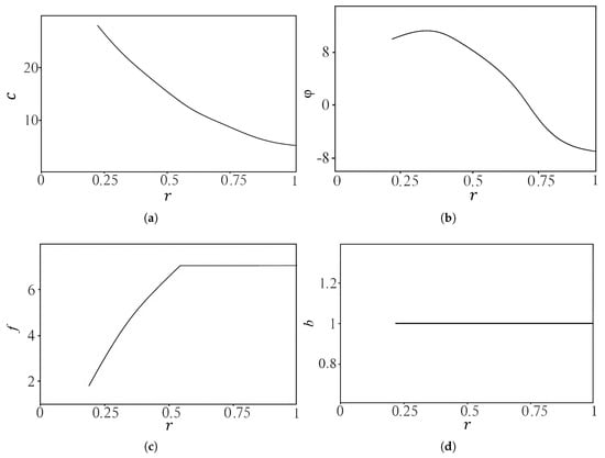
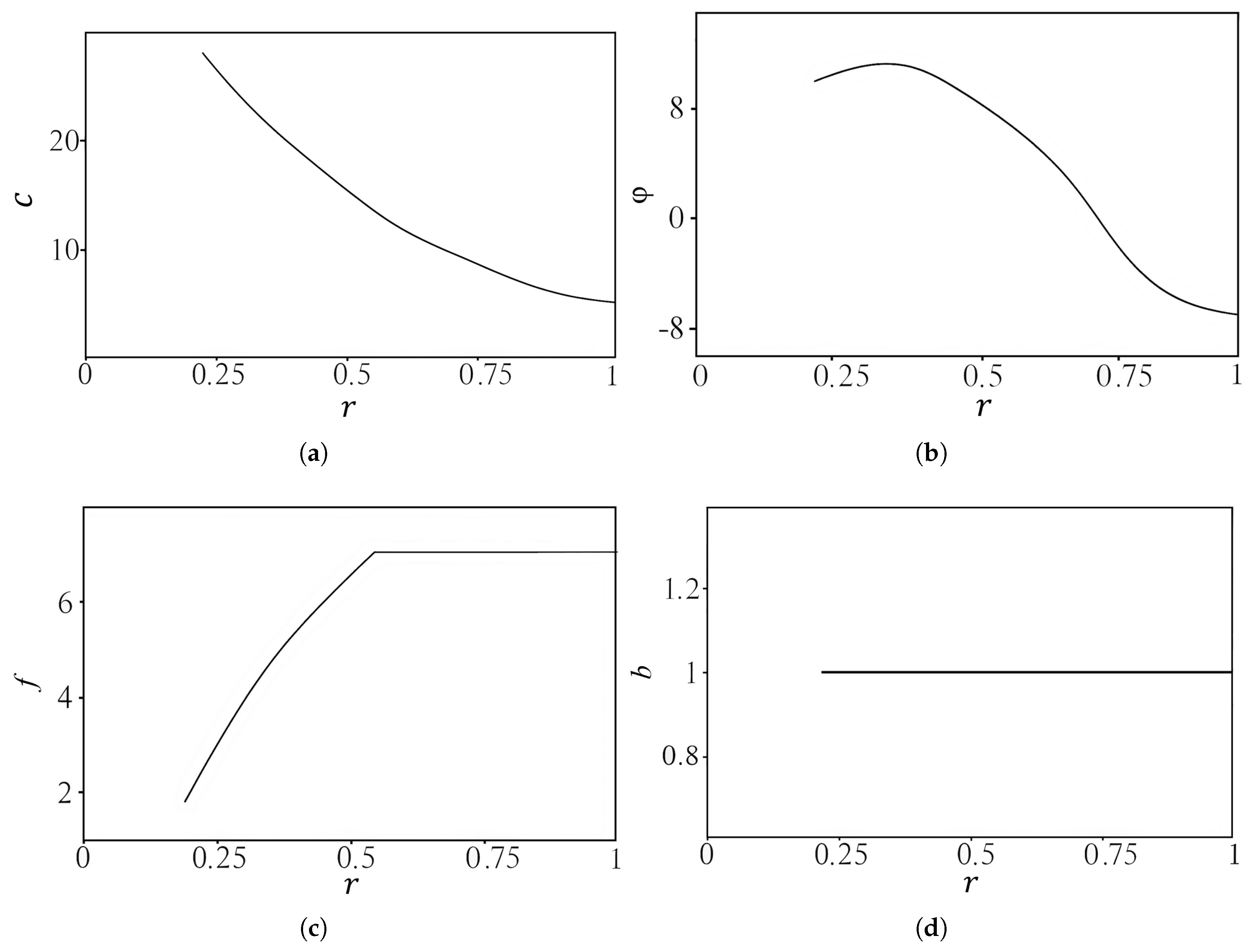
The parameters of the geometric model of a blade are set based on an analysis of open sources. Graphs from [1] were used to profile the fan blades. The distribution of the relative blade thickness c and curvature f is shown in the graphs, as well as the rotation angle and the chord length b of the blade along the relative propeller radius (the radius of the section plane divided by the total propeller radius). The VK1 air duct was modelled based on the relationships reported in [1]. The geometric parameters for the fan were taken from the K6–VK1 geometry of a four-bladed ducted fan with a 25% reduction in air-duct length. The duct diameter is 0.76 m [2].
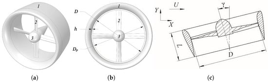
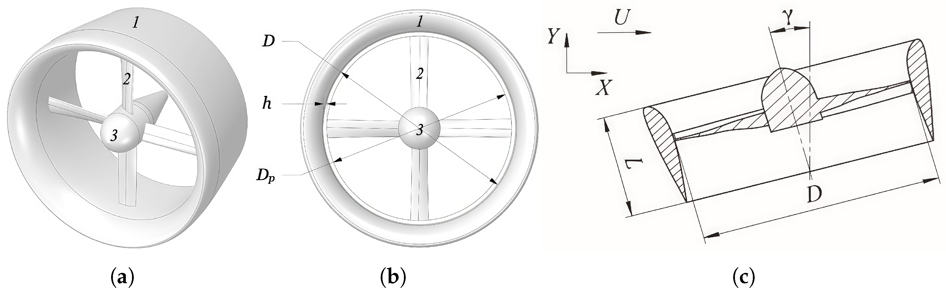
The design of the ducted fan consists of a heavily-loaded propeller (2) and an air duct (1) formed by the rotation of an airfoil. A general view of the ducted fan is shown in Figure 1, where the x-axis of the Cartesian frame of reference is aligned with the direction of the freestream airflow. The angles of deviation of the propulsor from the vertical are model parameters.
Figure 1.
Model of a four-blade ducted fan with a hub: (a) general 3D view; (b) front view; (c) axial cross-section through the rotation axis. 1—Duct (annular shroud); 2—blade; 3—fan hub; D—inner diameter of duct, m; —outer diameter of blade (tip-to-tip), m; h—clearance between blade tip and inner duct surface, m; U—freestream velocity, m/s; L—length of air duct, m; —deviation angle of propulsor from the vertical axis, °.
To increase thrust at low speeds and reduce tip loss when operating in ducts, the blade shape is rectangular. These blades have lower torsional stiffness compared to elliptical ones, so they are not suited for aircraft propeller applications due to the risk of stall flutter. In order to increase torsional stiffness, a larger relative thickness c is chosen, but this is not suitable for propellers because of the large wave loss in cruise mode. The chosen thickness, curvature, and shape of the airfoils provide high lift coefficients and delay separation. This, combined with a larger thickness, avoids stall flutter, allowing for a rectangular-shaped blade.
For the K184 propeller, in the peripheral sections of the blade with , an airfoil curvature of is accepted, which ensures continuous flow with high lift coefficients. At the root of the blades, with values of , the curvature is decreased, since a large relative thickness at the root section combined with a high curvature would lead to earlier separation of the flow.
The blade twist angle varies from near the hub to at the tip of the blade, which is much less than the typical twist angle found in propellers. This particular propeller has been designed for use at low speeds. The distribution of geometric parameters across the height is shown in Figure 2.
Figure 2.
Geometric parameters of the blade plotted against the relative radius r (where r is the local radial coordinate, , measured from the axis of rotation divided by the blade length L (equal to R of propeller)): (a) relative thickness of the airfoil c; (b) blade twist angle ; (c) relative curvature of the airfoil f; (d) relative chord length b.
The duct in a ducted fan is a rotating body with an aerodynamic airfoil in cross-section. It increases speed through the propeller inlet, reduces radial leakage, enhances thrust, and decreases blade moment. Key duct parameters include a relative width of , with being the smallest diameter; a maximum relative thickness of ; a maximum relative curvature of ; and a chord angle of to the axis of rotation. The blade rotation plane is positioned from the duct’s leading edge. The duct opening coefficient is and expansion coefficient is , where and are the diameters of the inlet and outlet sections of the duct. The overall diameter of the duct is 26% larger than the diameter of the blade.
2.2. Mathematical Model and Boundary Conditions
The flow induced by the rotation of the fan blades is governed by the compressible Navier–Stokes equations. The working medium is air, treated as an ideal gas with constant molecular viscosity and constant specific heats. Turbulent transport is modelled within the unsteady Reynolds-averaged Navier–Stokes (URANS) framework with the SST k– closure (Section 2.4). To extract the operating regime of the propulsor at acceptable computational cost, the simulation is organized into two stages. In the first stage, a steady solution in the rotating frame attached to the rotor (the Frozen Rotor formulation, equivalent to a single-position Multiple Reference Frame computation) provides a converged approximation of the time-averaged operating point. In the second stage, the same set of equations is integrated in time on a sliding mesh, with the first-stage solution used as the initial condition. The integral thrust and power coefficients reported in Section 3.1 and Section 3.2 are computed from the time-averaged URANS field.
In a coordinate system rotating with angular velocity , the conservation laws for mass, momentum and energy take the form
where is the velocity in the rotating frame, the density, p the static pressure, the total specific energy and the position vector relative to the rotation axis. The two source terms in (2) represent the Coriolis and centrifugal forces. The viscous stress tensor and the heat flux are
where is the molecular viscosity, the eddy viscosity provided by the turbulence closure, k the turbulent kinetic energy, and . The system is closed by the ideal-gas relation with .
The speed and total temperature are specified at the inlet boundary of the computational domain, and the static pressure is fixed at the remaining boundaries. The intensity of turbulence at the inlet boundary is 5%, and the ratio between turbulent viscosity and laminar viscosity for air is 10. No-slip and adiabatic boundary conditions are specified on the walls.
The simulation is performed on an unstructured mesh composed of tetrahedral elements. The total number of elements is approximately , and the maximum element size in the main part of the domain is 0.1 m. The near-wall region is resolved by a prismatic boundary-layer mesh with a total thickness of 0.1 mm, 8 layers and a growth factor of 1.1. The first cell height is chosen so that the dimensionless wall distance remains below unity () over the entire blade and duct surface. The fine mesh refinement near the walls eliminates the need for wall functions, providing greater flexibility in the choice of the turbulence model. A formal Grid Convergence Index (GCI) study has not been performed in the present work, because the chosen mesh density and near-wall resolution are consistent with those validated for ducted-fan and propeller flows in earlier studies of the same configuration [26,28,32], and the integral characteristics (thrust and torque) are monitored along the iteration history to confirm convergence.
The two-stage solution procedure is organized as follows.
Stage 1—Frozen Rotor initialization: The unsteady terms in Equations (1)–(3) are dropped and the steady system is solved with the rotor held at a fixed azimuthal position. The relative motion between the rotor and stator meshes is suppressed and the rotor–stator interface acts as a stationary mismatched interface. The Coriolis and centrifugal source terms in (2) make the steady solution in this frozen configuration a valid time-averaged approximation of the underlying periodic flow, provided that the rotor–stator interaction does not introduce significant unsteadiness at the blade-passage frequency. The applicability of this approximation for ducted propellers and shrouded rotors has been documented in [10,11,13,15] and surveyed in [19]. The Frozen Rotor stage delivers a converged approximation of the operating regime that serves as a high-quality initial condition for the second stage.
Stage 2—URANS with sliding mesh: Starting from the Frozen Rotor field, the full unsteady Equations (1)–(3) are integrated in time on a sliding mesh, in which the rotor sub-domain rotates relative to the stator sub-domain at the prescribed angular velocity . At every time step, the conservative variables are exchanged across the non-conformal sliding interface so that the rotor–stator interaction is resolved. The sliding-mesh URANS framework reproduces the time-dependent loading on the blades and the unsteady tip-vortex dynamics that drive the loss budget at large tip clearances. Temporal integration is performed using the third-order Runge–Kutta method, and the time step is selected so that the blade tip moves no more than in azimuth for each step; i.e., the time step is determined relative to the desired rotational speed. The same sliding-mesh URANS strategy was applied to the analysis of wind effects on a ducted fan [33].
All numerical computations conducted during the study were executed using the OpenFOAM 11 CFD software.
2.3. Numerical Method
To discretize the governing equations, the finite volume method on unstructured grids and the median control volume are used [34]. Integration over time is performed using the 3rd-order Runge–Kutta method. Discretisation of inviscid flows is performed using the MUSCL (Monotonic Upstream Schemes for Conservation Laws) scheme, while viscous flows are discretized using a centred scheme with second-order accuracy. The MUSCL scheme allows for increasing the order of spatial approximation without losing monotonicity in the solution, satisfying the TVD (Total Variation Diminishing) condition, and combining centred finite differences with a dissipative term of the second order. To switch between which flux limiter designed with characteristic variables is used, the gradient and the pseudo-Laplace operator at the mid-point of a control volume face based on relations that are adapted for calculations in highly stretched cells in the boundary layer are found to solve a system of finite-difference equations. A geometric multigrid technique is used for this purpose. A sequence of grids with different resolutions is generated using the edge-collapsing method [35].
The results of numerical modelling are the pressure and velocity fields, both in the computational domain and directly on the blade surface, which allow us to determine the aerodynamic properties of the propulsive system in different modes. The thrust force created by the fan blades , the thrust force created due to circulation around the airfoil of the duct , the drag force of the propeller hub , and the moment of resistance to rotation M are determined. The resulting force makes it possible to determine the total thrust of a given ducted fan as . The thrust coefficient is found as , and the power coefficient is calculated as , where is air density, D is blade diameter, and T is thrust force. The required power on the shaft is determined as [W], where n is rotation speed [rpm] and M is the moment of resistance to rotation [N m].
2.4. Turbulence Model
Two series of calculations were carried out with the SA and SST turbulence models proposed in [36,37].
The Spalart–Allmaras model [36] solves a single transport equation for the modified turbulent viscosity ,
with the eddy viscosity recovered as . The Menter SST k– model [37] solves two transport equations,
where is the production term, is the SST blending function, and the model constants are taken from [37].
In these calculations, the angle of attack of fan blades is varied, and graphs of the dependence of thrust coefficient on power coefficient are plotted, which are compared with experimental data. The variable parameter is the angle of attack of the blade. The rotation speed remains constant and equal to 1200 rpm. The oncoming flow velocity is 0.05 m/s. The direction of the oncoming flow is axial. The Reynolds number at the periphery of the blade is , where u is the peripheral speed, b is the chord, and is the kinematic viscosity. For the given conditions, .
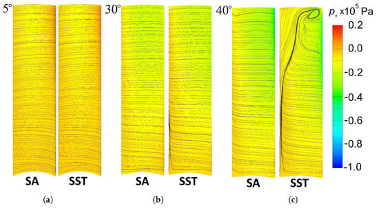
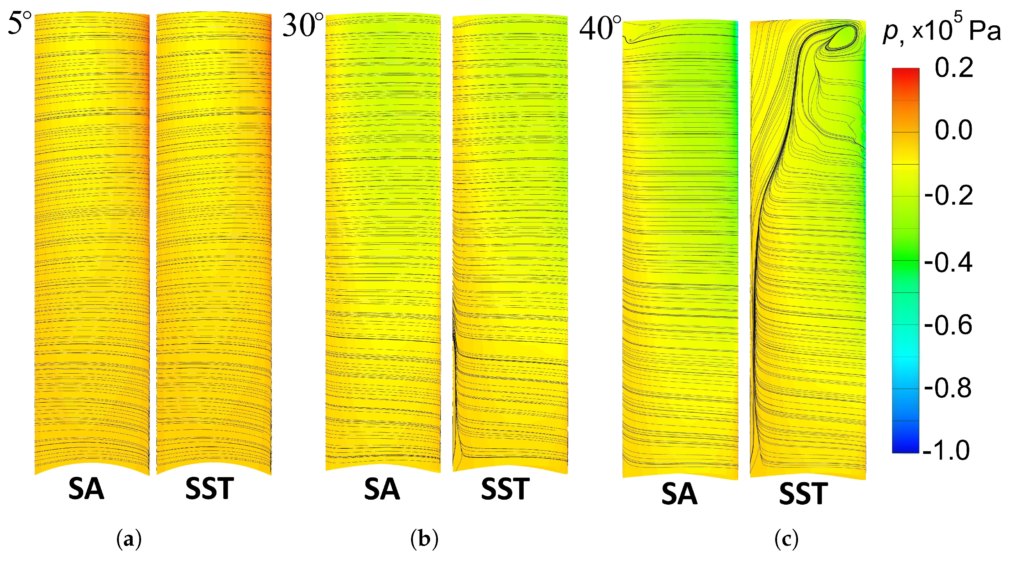
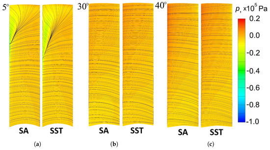
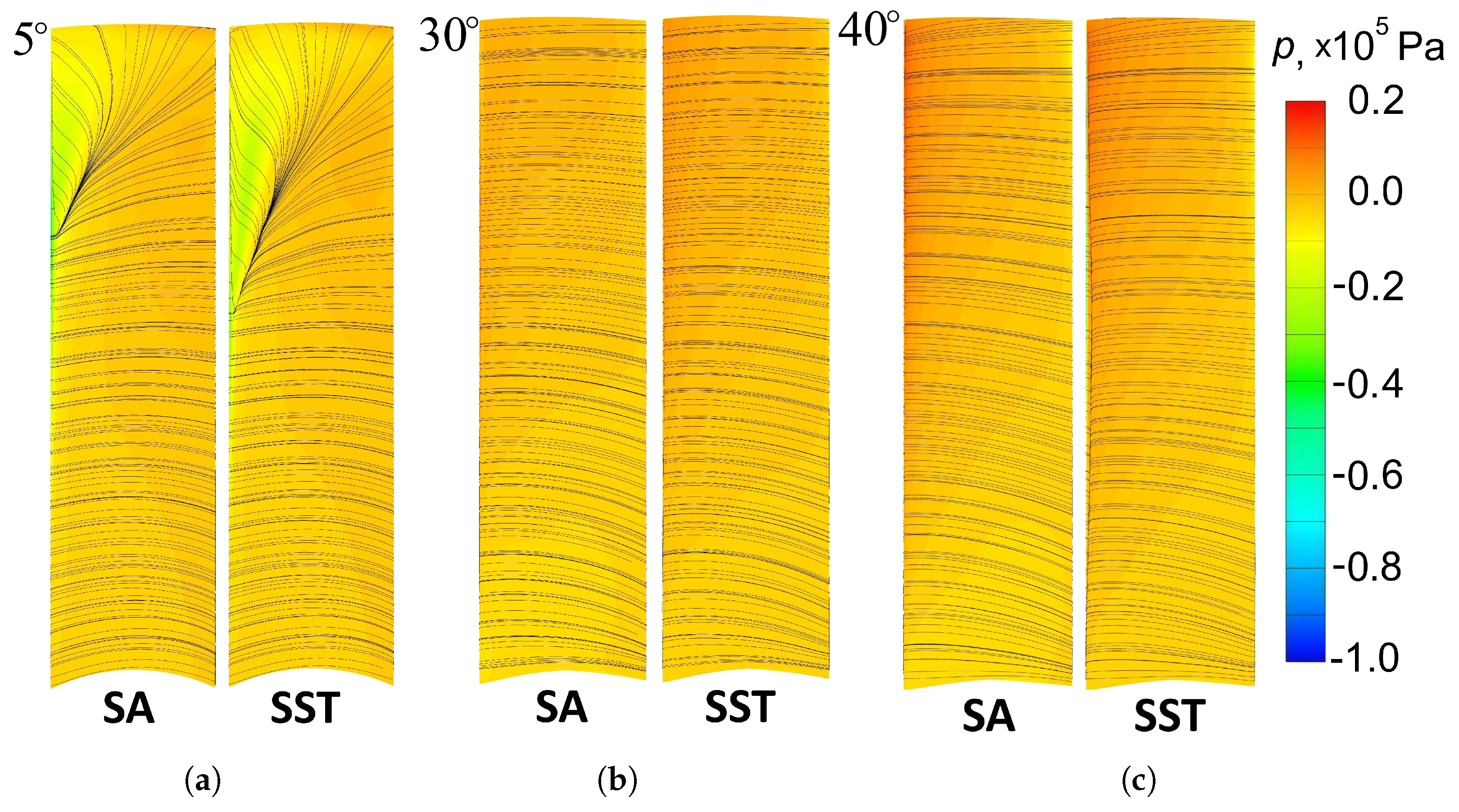
The limiting streamlines on the blade surface make it possible to evaluate the nature of flow around the elements of the ducted fan and the type of flow behind it. Streamlines and pressure contours at attack angles of 5, 30 and 40 degrees are presented in Figure 3 and Figure 4. At an attack angle of 40 degrees, when using the SST model, a vortex appears on the front surface near the periphery, which causes a sharp drop in the dimensionless coefficients. At smaller angles, there is a slight shear from the front surface near the trailing edge, and it becomes more pronounced as the attack angle increases.
Figure 3.
Limiting streamlines and static-pressure contours on the upstream (suction) side of the blade for blade attack angles of (a) , (b) and (c) (SST closure, rpm, axial inflow at 0.05 m/s).
Figure 4.
Limiting streamlines and static-pressure contours on the downstream (pressure p in Pa) side of the blade for blade attack angles of (a) , (b) and (c) (SST closure, rpm, axial inflow at 0.05 m/s).
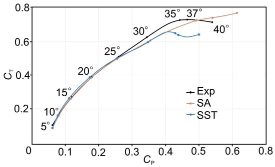
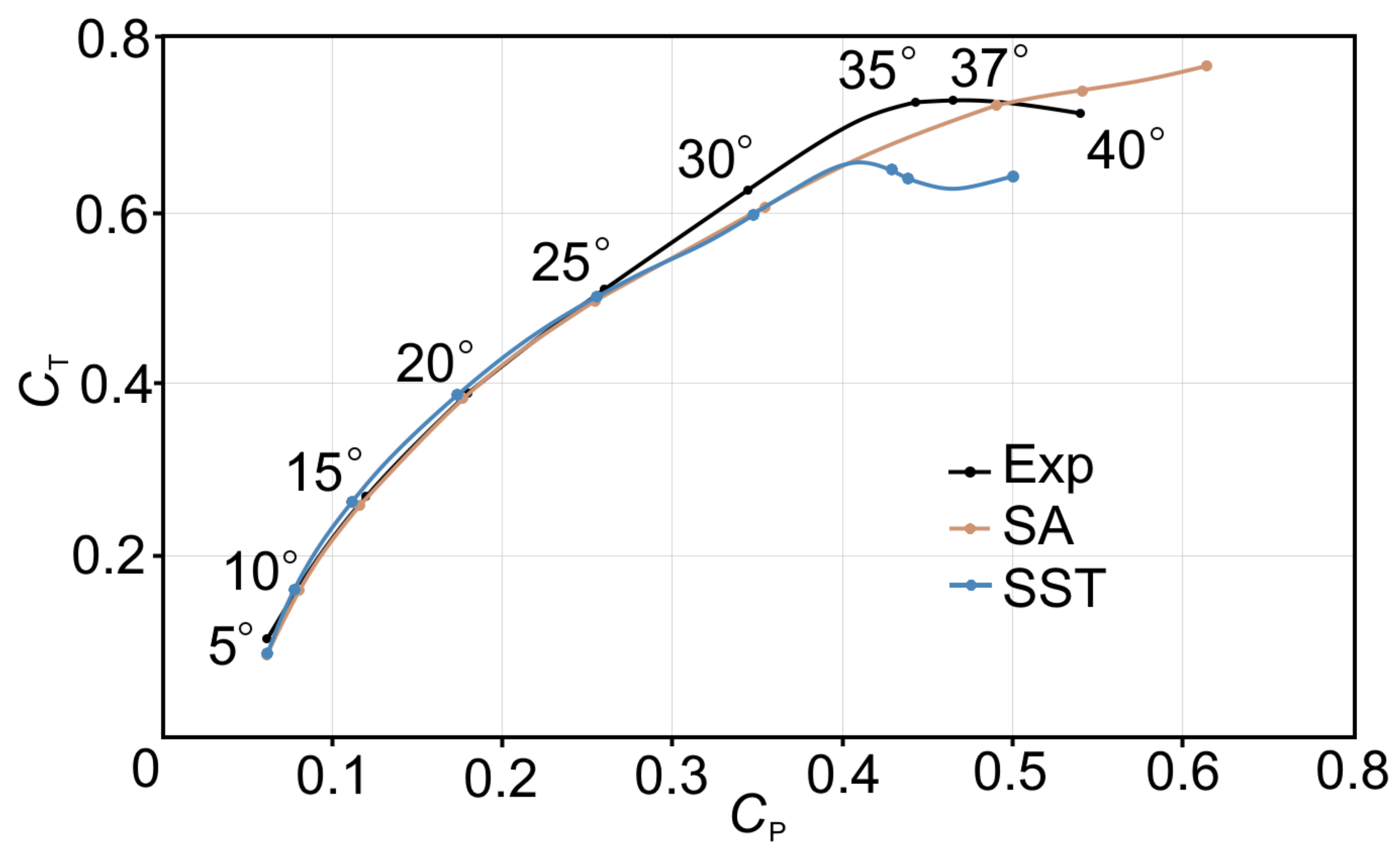
Figure 5 compares the thrust–power characteristic predicted by the Spalart–Allmaras (SA) and the SST k– closures with the experimental baseline of Ostroukhov [1] for the K184/VK1 configuration. The blade attack angle is varied along each curve, while the rotational speed and the inflow conditions are held fixed.
Figure 5.
Dependence of the thrust coefficient on the power coefficient for the K184/VK1 ducted fan: comparison of the SA and SST closures with the experimental data of Ostroukhov [1].
Up to a blade attack angle of about , both closures follow the experimental curve within the scatter of the measurements. In this moderately loaded regime the boundary layer on the blade is for the most part attached, the suction-side flow is dominated by a thin turbulent layer, and the integral loading is governed largely by the inviscid pressure distribution. Either closure therefore reproduces the integral thrust and power coefficients with comparable accuracy.
Above the picture changes. The experimental curve continues to rise smoothly and then, in the vicinity of 35–, the dimensionless thrust drops abruptly. This drop is the signature of a global stall on the blade, in which a leading-edge separation bubble loses its reattachment and large-scale separated flow takes over the suction side of the airfoil. Both computed curves depart from the experimental baseline above and underpredict the dimensionless thrust over the heavy-load range, but they do so in qualitatively different ways.
The SA prediction grows almost monotonically with the attack angle and shows no evidence of a thrust break-down. The model treats the entire blade boundary layer as fully turbulent from the leading edge onwards and therefore suppresses the laminar separation bubble that controls the loading at moderate-to-heavy loads. Thus, the SA curve strongly delays the boundary-layer separation, and the global flow separation from the blade occurs outside the considered range of blade attack angles.
The SST closure also underpredicts the dimensionless thrust above , with values systematically below the measured ones, yet it qualitatively reproduces the experimental break-down. The SST curve flattens and then drops in the vicinity of the stall angle, mirroring the trend observed in the experiment. This behaviour is consistent with the ability of SST to represent gross flow separation through its blending into a k– formulation in adverse pressure gradients. What SST cannot represent, and what is responsible for the systematic offset between the computed and the measured curve in the heavy-load range, is the laminar-to-turbulent transition that controls the development of the leading-edge separation bubble itself.
If we consider the initially laminar boundary layer as completely turbulent, we will overestimate the friction resistance, as in the case of SA, which will lead to a decrease in the effective lift on each blade section and the overall thrust. The differences seen at angles of attack greater than in Figure 5 stem from the absence of a laminar–turbulent transition model in the SA and standard SST closures.
3. Results
3.1. Effect of Blade Angle
The calculation of the flow around a ducted fan with optimal angles of attack for the fan blades relative to the oncoming flow was carried out. The oncoming flow speed varied from 25 to 75 m/s. For each value of oncoming flow velocity, the optimal rotation angle of fan blade was calculated (60.64 degrees at m/s, 74.29 degrees at m/s, 79.38 degrees at m/s). The angles of deviation of the blade from the vertical are 15, 30 and 45 degrees. The duct length is mm.
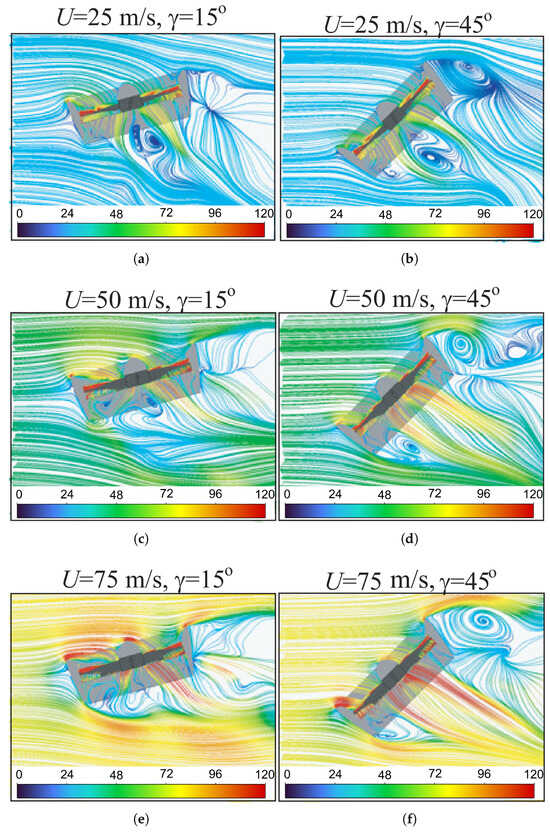
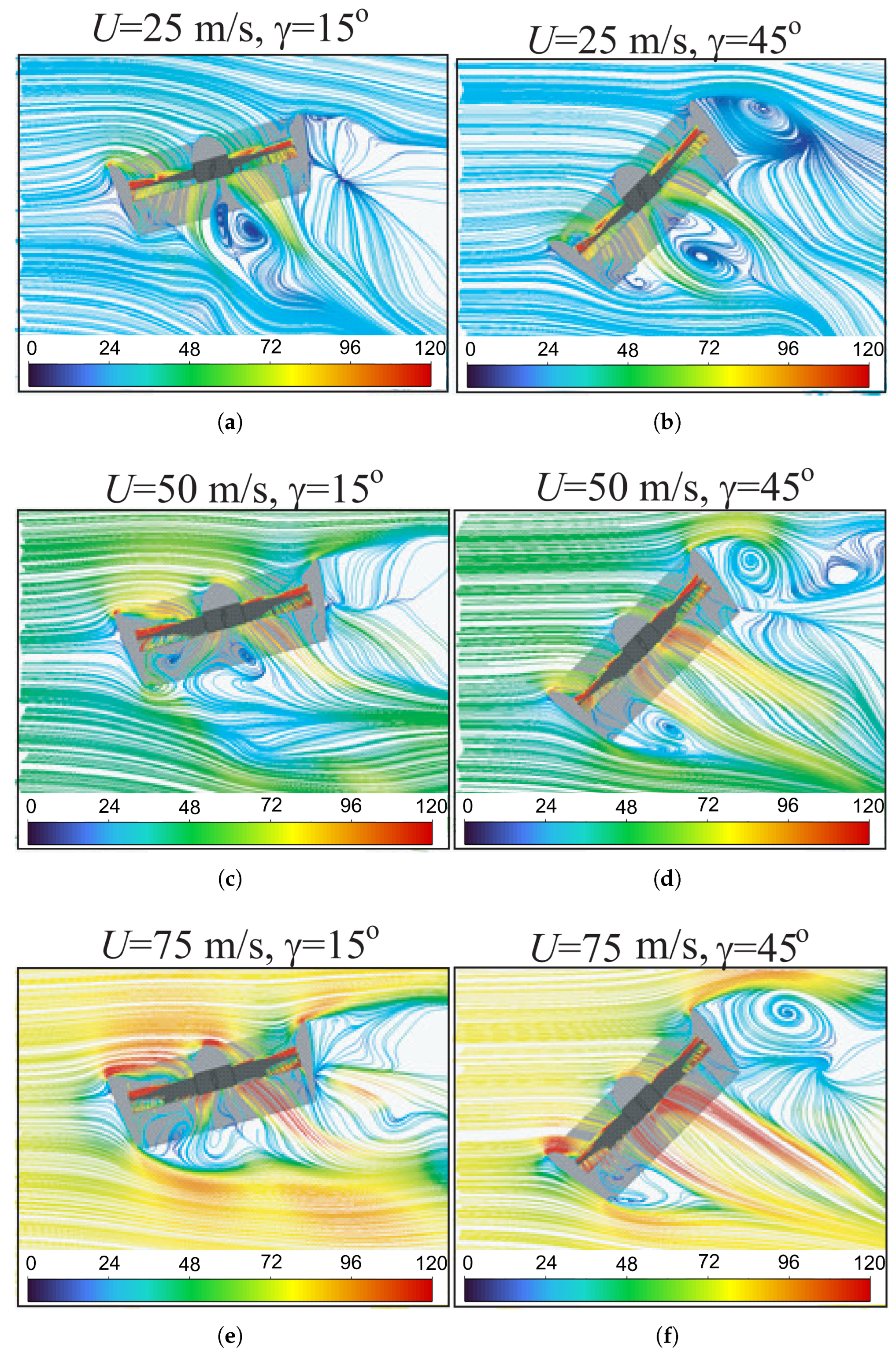
Streamlines at different free flow velocities and angles of deflection of the ducted fan from the vertical are shown in Figure 6. In the flow in front of the blade, the streamlines are directed along the axis of rotation into the duct, resulting in the effect of suction of free air into the duct. In this case, the velocity decreases along the radius of the duct and becomes negligible on the outer surface. Behind the blade there is a significant acceleration of the axial flow velocity on a cylindrical surface on the order of the radius of the duct and its twisting, co-directed with the direction of rotation of the blade. As the radius decreases and the distance increases, the axial velocity decreases and, as a consequence, the amount of flow swirl increases. Behind the central body, where the axial velocity is practically zero, the streamlines are twisted into a bundle. In the lower part of the flow, in the vicinity of the rotation axis, spiral vortices are formed.
Figure 6.
Streamline patterns around the ducted fan for various freestream velocities U and angles of deviation from the vertical : (a) m/s, ; (b) m/s, ; (c) m/s, ; (d) m/s, ; (e) m/s, ; (f) m/s, .
When an aircraft moves laterally at a specific angle, the velocity field in the propeller’s rotation plane becomes asymmetrical. This occurs because the airflow disturbed by the front edge of the ring enters a particular sector of the propeller’s swept area. This causes the propeller blades to experience varying loads. As the lateral speed increases, the incoming airflow separates from the ring’s surface, creating a wide, non-stationary separation zone where the propeller blades operate. In the figure, we see that as the lateral flow velocity rises (while keeping the angle of attack constant), the velocity distribution undergoes fluctuations due to non-stationary separation, varying within certain limits.
In front of the blades and to the side of them there is a suction zone in which the flow speed increases as it approaches the blades. The intensity of flow decreases as it approaches the axis of rotation of the blade, where low-speed turbulent structures are observed near the butt parts of the blades. Behind the fan, the flow velocity reaches its maximum in the cone below the blade tips and decreases further downstream from the fan. The most intense turbulent structures are tip vortices coming off the blade tips and twisting into characteristic tapering spirals descending downstream from the plane of rotation of the fan. With distance from the rotor disk downstream, the intensity of the turbulent structures decreases.
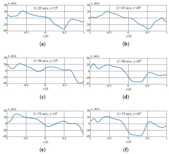
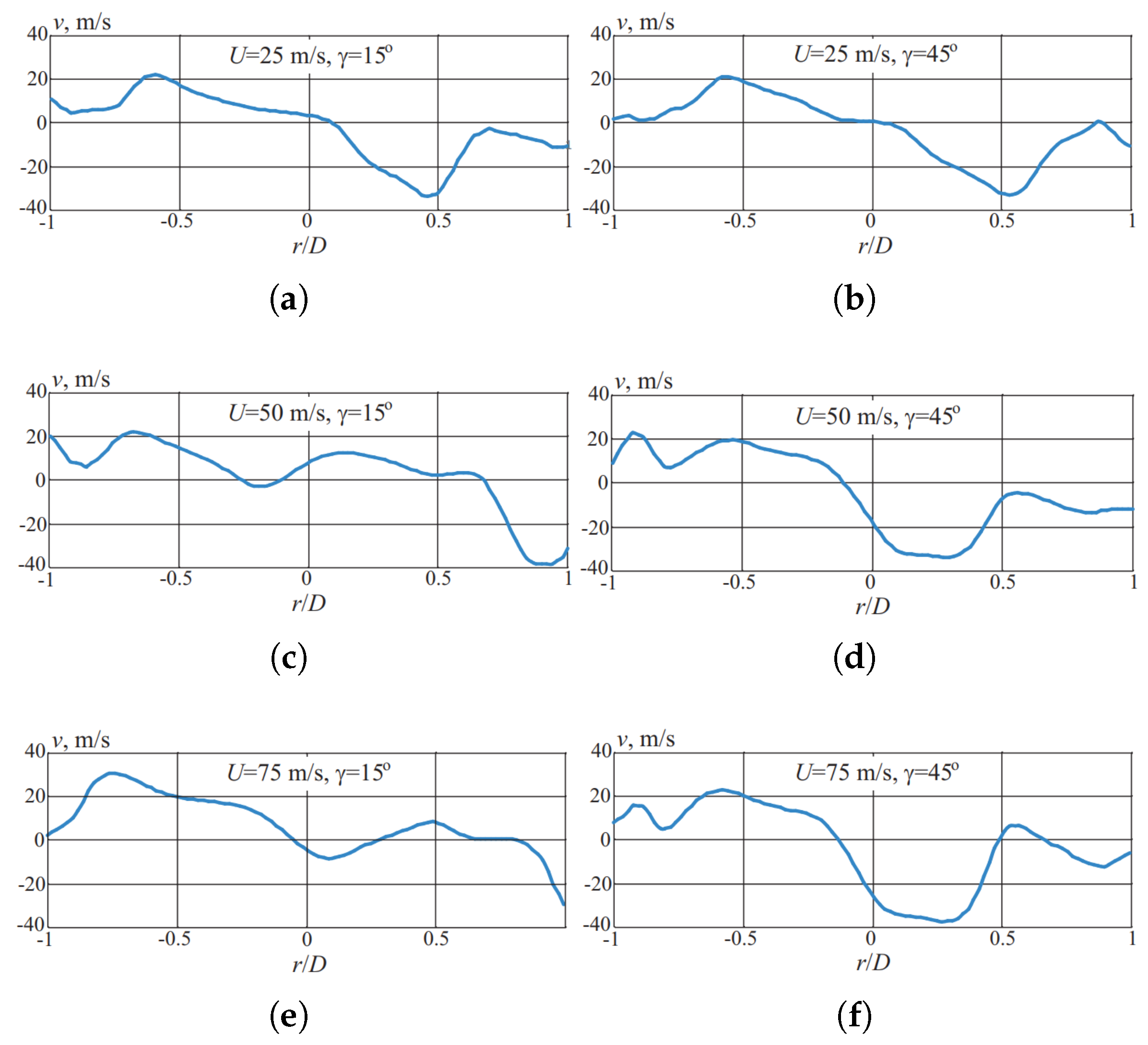
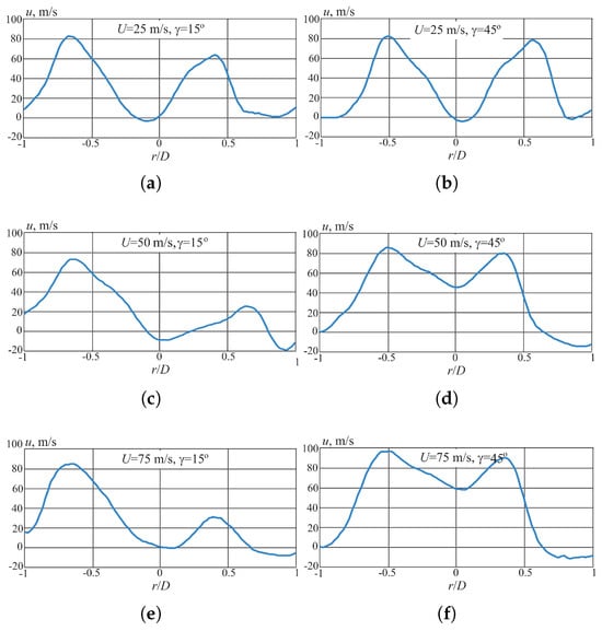
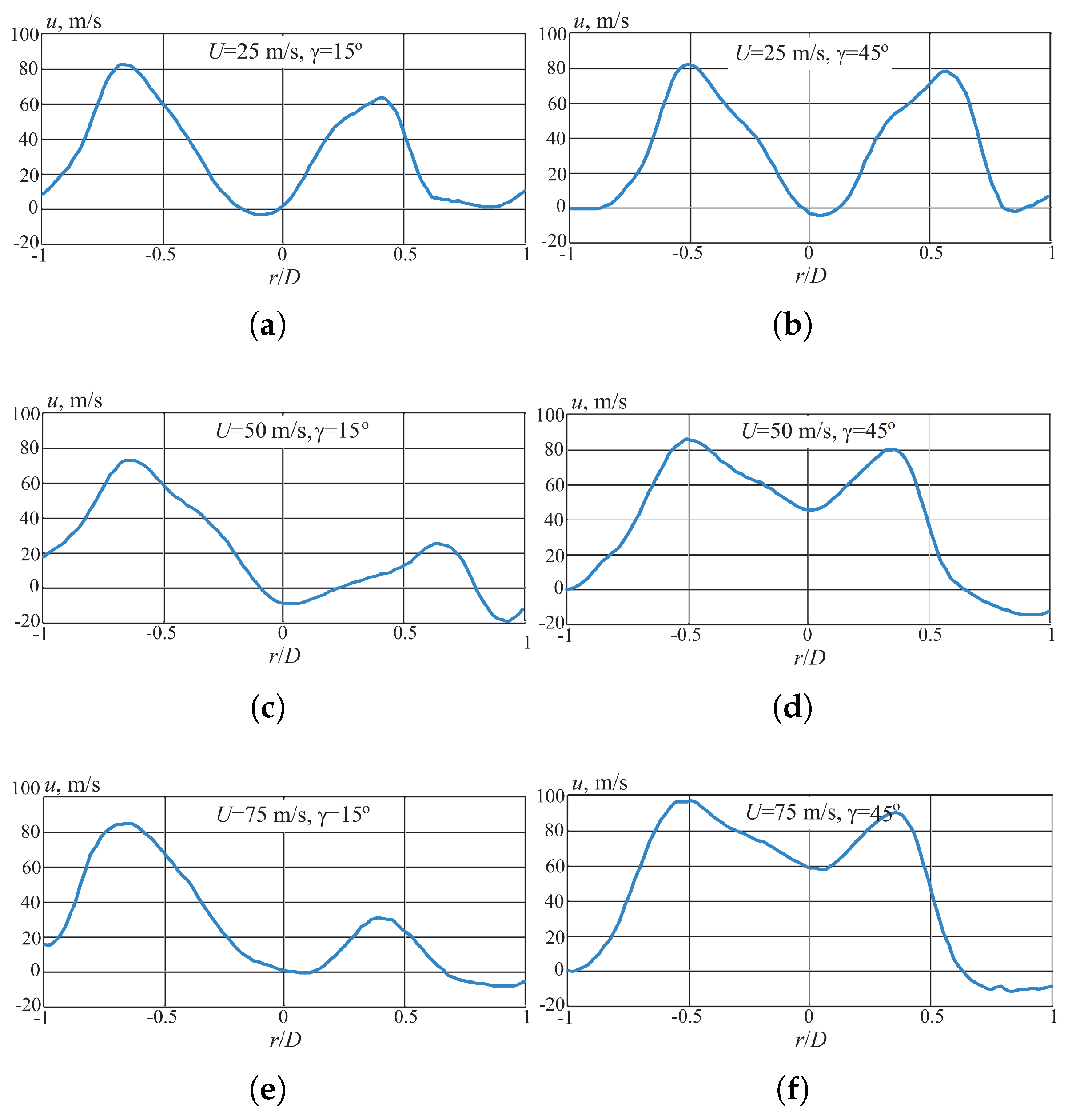
The distributions of axial and circumferential velocities in the outlet section of the duct at different incoming flow velocities and angles of deviation of the ducted fan from vertical are shown in Figure 7 and Figure 8.
Figure 7.
Radial distribution of the axial velocity component in the duct outlet section for various U and values: (a) m/s, ; (b) m/s, ; (c) m/s, ; (d) m/s, ; (e) m/s, ; (f) m/s, . The abscissa is the dimensionless radial coordinate.
Figure 8.
Radial distribution of the circumferential (swirl) velocity component in the duct outlet section for various U and values: (a) m/s, ; (b) m/s, ; (c) m/s, ; (d) m/s, ; (e) m/s, ; (f) m/s, . The abscissa is the dimensionless radial coordinate.
When an aircraft moves laterally at a specific angle, the velocity field in the propeller’s rotation plane becomes asymmetrical. This occurs because the airflow disturbed by the front edge of the ring enters a particular sector of the propeller’s swept area. This causes the propeller blades to experience varying loads. As the lateral speed increases, the incoming airflow separates from the ring’s surface, creating a wide, non-stationary separation zone where the propeller blades operate. In the figure, we see that as the lateral flow velocity rises (while keeping the angle of attack constant), the velocity distribution undergoes fluctuations due to non-stationary separation, varying within certain limits. As the angle of the propeller increases, this asymmetry, caused by the skew of the velocity vector and the initial asymmetric flow disturbance, becomes smoother.
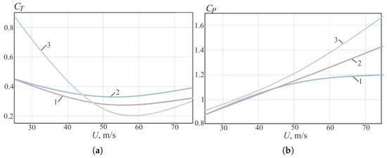
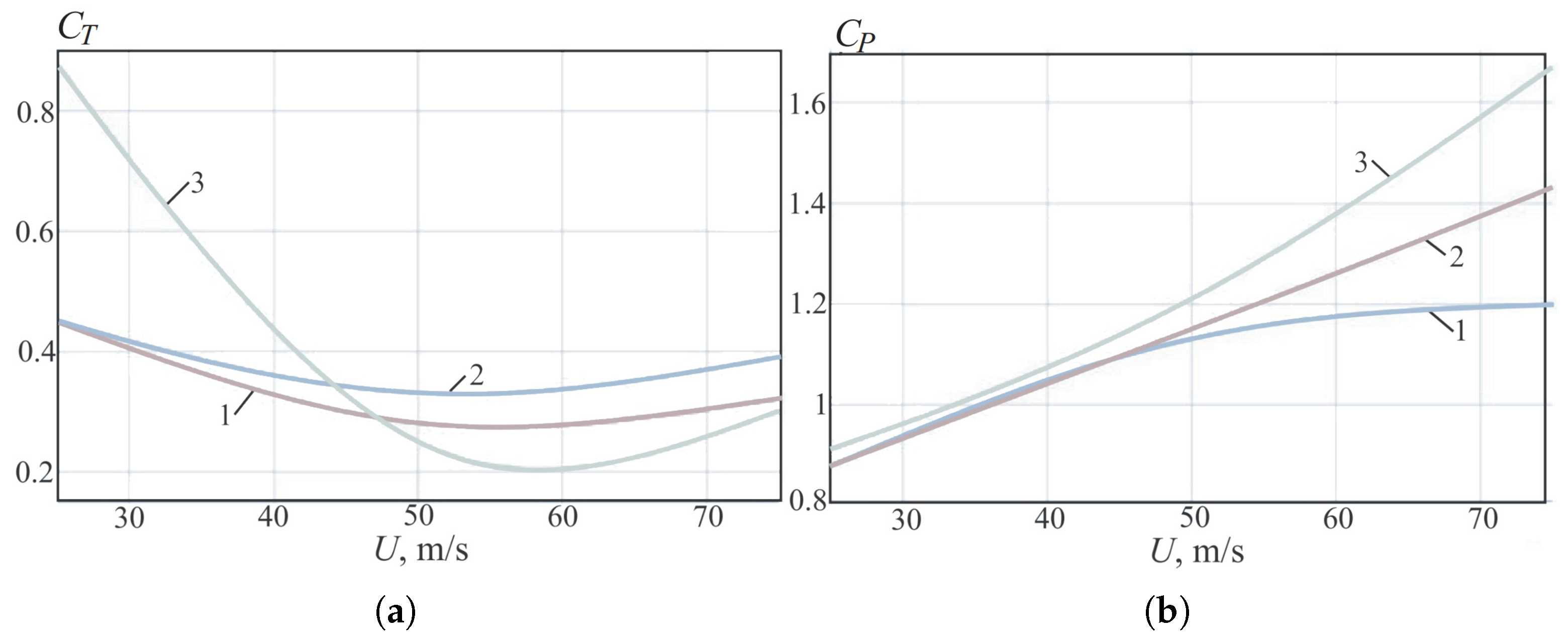
The influence of the speed and angle of deviation of the blade from the vertical on the thrust characteristics is shown in Figure 9.
Figure 9.
Dependence of (a) the thrust coefficient and (b) the power coefficient on the freestream velocity for various angles of deviation of the ducted fan from the vertical ( (curve 1), (curve 2), (curve 3)).
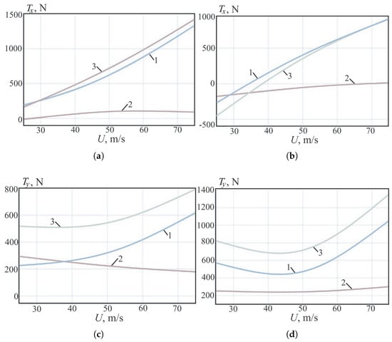
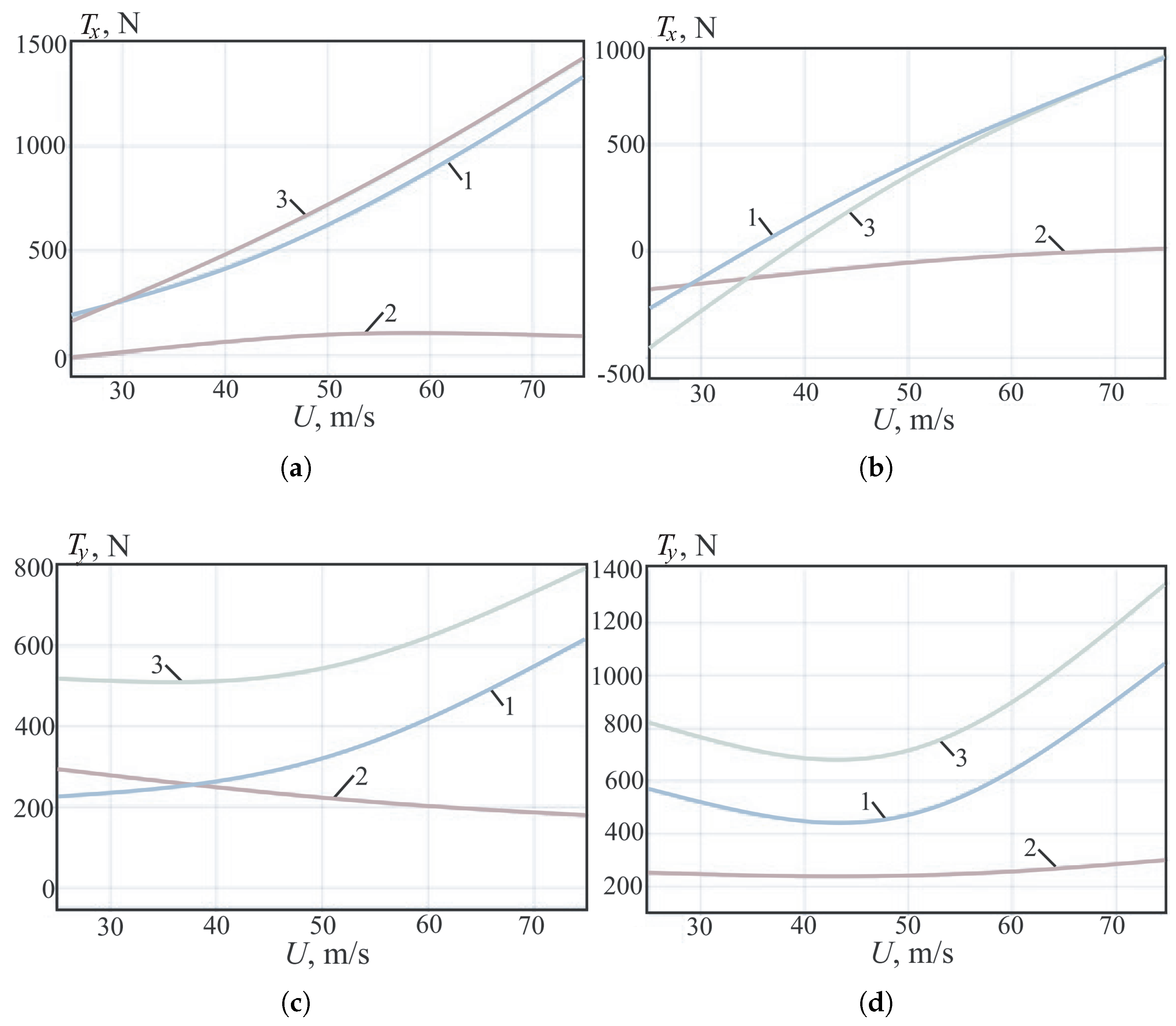
The results obtained show both the change in the total thrust force coefficient and the change in its components (fan thrust force and duct thrust force) depending on the speed of oncoming flow and angles of deflection of the ducted fan from the vertical. The forces acting on the ducted fan and its elements for various velocities of oncoming flow and angles of deviation of the ducted fan from the vertical are shown in Figure 10. The relative thrust coefficient of the fan is a small value of the total thrust. The high load capacity is associated with the optimal configuration of the duct, which has a relatively large radius of the curvature of its collector, and a sufficiently long diffuser [9].
Figure 10.
Components of the thrust force projected onto the x- and y-axes versus freestream velocity for the duct (curve 1), the fan blades (curve 2), and the combined duct–fan system (curve 3): (a) at ; (b) at ; (c) at ; (d) at .
The total thrust coefficient and the thrust coefficient of the fan at a zero angle of attack increase with increasing speed due to an increase in the mass flow of air passing through the fan. When the angle of deflection of the blade from vertical changes, the total thrust decreases significantly due to a drop in the thrust of the duct.
3.2. Effect of Tip Clearance
In the gap between the fan blade tip and the aerodynamic duct, a low-Reynolds flow occurs from the lower surface of the blade to the upper surface (the flow is laminar). The fan blades exhibit an extensive laminar boundary-layer zone on the downwind side. Rotation of a fan in the presence of a gap is accompanied by the formation of vortices of different sizes and intensity at the blade tips.
The size of the internal diameter of the air duct in each of the considered cases remains unchanged due to the need to maintain the air mass flow rate for a relevant comparison of the thrust characteristics. Changing the tip clearance h is achieved by slightly reducing the length of the blade. The influence of the tip clearance was studied with its relative value equal to 0.02, 0.015, 0.008 and 0. In the absence of a tip clearance (), it is assumed that the fan blades are embedded in the inner surface of the air duct and rotate together with the annular segment of this surface. Calculations are carried out for blade angles of attack of 16 and 32 degrees. The section relative to which the angle of blade attack is set is located at 75% of the blade length.
Table 1 shows the results of calculations demonstrating the influence of the clearance size on thrust, torque, power on the shaft, and dimensionless thrust and power coefficients.
Table 1.
Calculated thrust, torque, shaft power and dimensionless coefficients at constant rotational speed ( rpm) for two blade angles of attack (16° and 32°) and four relative tip clearances .
Table 1 reads as follows. Each row corresponds to a fixed blade attack angle (16° or 32°, column 1) and one of the four relative tip clearances (column 2). Columns 3 and 4 give the dimensionless thrust and power coefficients; columns 5–7 give the corresponding dimensional torque on the shaft M, the shaft power and the integrated thrust force P. Two main trends are visible. First, increasing from 0 to 2% reduces the thrust at the moderately loaded angle of 16° from 91.5 to 84.5 N, i.e., by about 8%; at the heavily loaded angle of 32° the same change reduces the thrust by 29% (from 286.6 to 202.5 N). Second, the power coefficient does not decrease monotonically with : at 16° it has a minimum at (1284 W vs. 1782 W at ), which is the basis for the optimal-clearance result discussed below.
At both blade attack angles, as the clearance increases, the thrust force decreases almost monotonically. This is due to flow of part of the oncoming flow through the clearance between the blade tip and inner surface of the duct, avoiding the interaction of airflow with the working surfaces of the blades, and a reduction in the area of the working surface of the blades due to the increase in clearance. In this case, a change in flow structure associated with formation of tip vortices at the blade tips also makes a contribution. These vortices have a particular influence on the amount of power required to drive and rotate the fan at a given speed, since the appearance of separated vortex flows of different configurations leads to a significant redistribution of pressure and changes in the size and position of characteristic flow zones on the working surface of the blade.
An assessment of aerodynamic characteristics when using a finite-power fan was also carried out. To do this, after obtaining the dimensionless characteristics, the fan rotation speed was changed to values that can be achieved for the target power value. The value W per propulsion unit was taken as such a target value. Table 2 presents the results of a numerical calculation with the reduction of different ducted fan designs to a single power value by changing the rotation speed. At the same time, the values of the dimensionless coefficients are preserved (the operating mode that is obtained when changes are made to the design of blade is maintained). If, with a large angle of blade attack and a heavy load on the fan, thrust drops significantly with increasing clearance, the situation is then different with a moderate load. The thrusts at clearances and 1.5% are almost equal (there is no need to strive to endlessly reduce the clearance), which is technologically difficult. It is interesting that when studying moderately loaded fans with a given shaft power ( W), the optimal value of is obtained (Table 2).
Table 2.
Calculated thrust and torque after rescaling the rotational speed of each design to deliver a fixed shaft power W per propulsion unit, for two blade attack angles (16° and 32°) and four relative tip clearances .
For heavily loaded fans, thrust drops as expected with increasing clearance (there is no need to reduce the clearance below , since thrust does not increase). There is a certain optimum clearance, the value of which depends on the angle of attack of the blades. With an angle of attack of 16 degrees and clearance of 1.5%, the thrust is almost the same as with a clearance of 0.8%, but the power on the shaft is less. At a given power on the shaft, the blade with a clearance of 1.5% has maximum thrust.
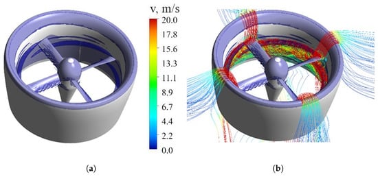
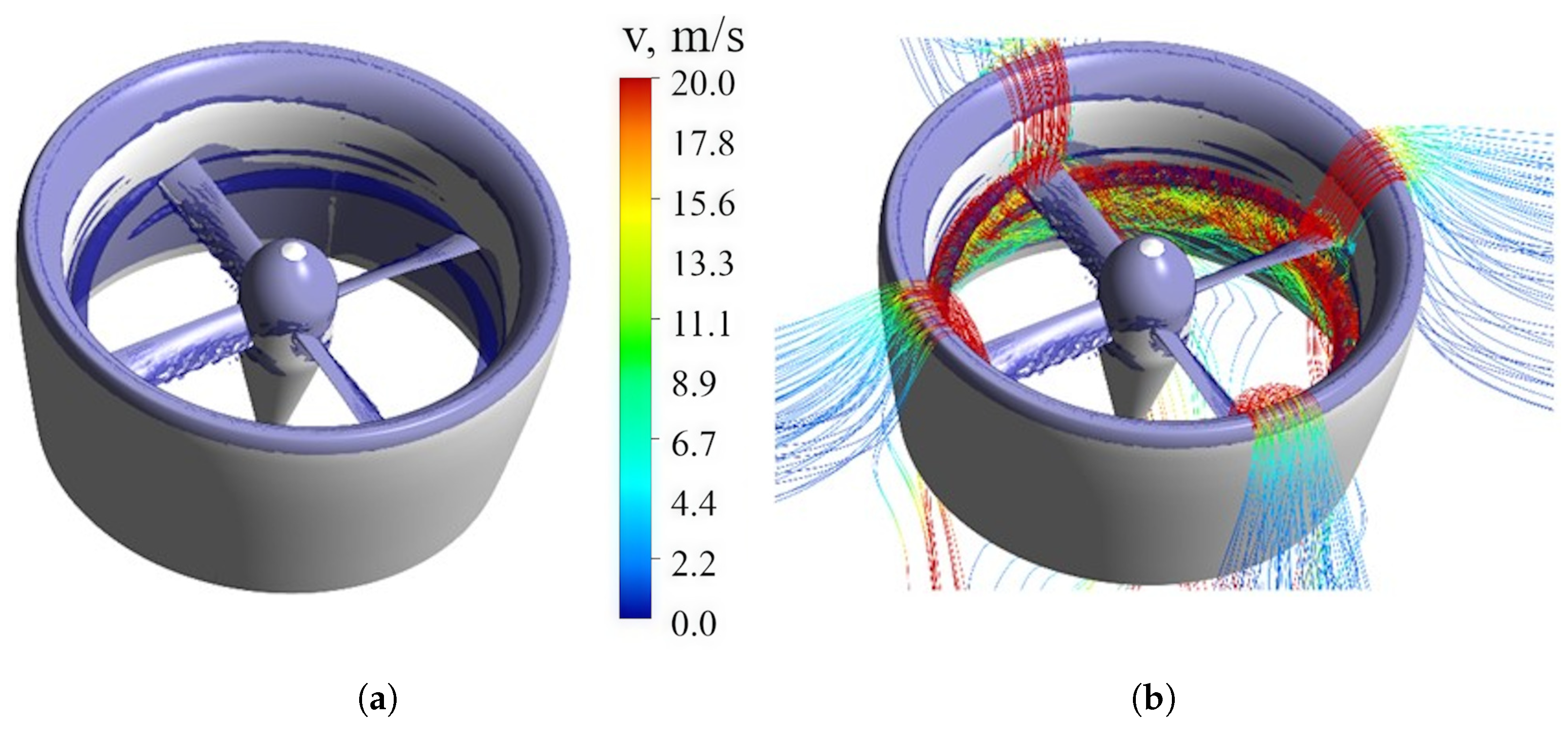
In Figure 11, we show streamlines and isosurfaces of the Q-criterion () for an attack angle of 32 degrees and a clearance of 2.0%. The vortex core has a strong influence on airflow around the blades. When the clearance is 2%, the flow incident on blade is strongly twisted and entrained in a vortex spiral flow near the walls of the air duct. The specific behaviour of the streamlines is associated with the emergence of intense stable vortex structures. Strongly twisted by the initial region of the vortex flow, the flow is carried to the centre of the air duct, pressing the core of the vortex and the airflow entrained by it against the walls of the duct. Thus, the decay of the vortex flow of the tip vortex is delayed and occurs much later. On the blades, there is a transition from laminar flow (irrotational regions) to turbulent flow. The tips of the blades leave behind a turbulent vortex wake. The vortex core has an extension of more than a quarter of the circumference of the blade duct.
Figure 11.
Isosurfaces of Q-criterion (a) and streamlines (b) at a blade angle of and clearance of 2.0%.
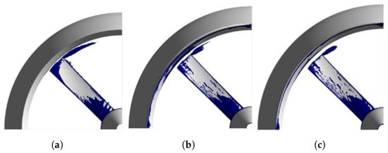
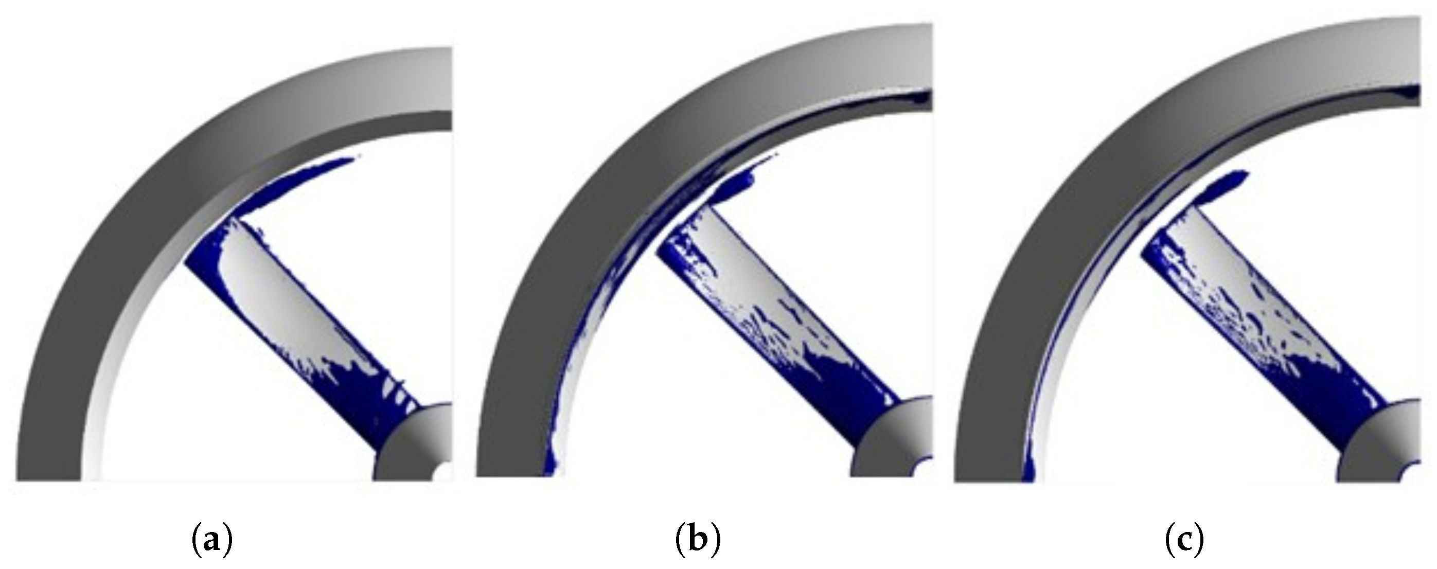
An analysis of flow in the vicinity of the clearance at a blade angle of 16 degrees shows that thrust losses are simultaneously influenced by two factors, flow from a high-pressure region to a low-pressure region and the vortex core formed in the clearance. The larger the value of h, the greater the thrust loss due to overflow. The intensity of eddy losses is affected differently by the clearance size. At small h, an intense thin vortex core is formed, which spreads over a considerable distance and greatly affects the flow behind the fan (Figure 12a). With large clearance, its influence on the formation of a vortex is minimal (Figure 12b,c), but the nature of flow inside the duct is such that the vortex is quickly washed out; therefore, usually in ducted fans the tip losses via vortex formation are less than in isolated fans.
Figure 12.
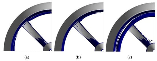
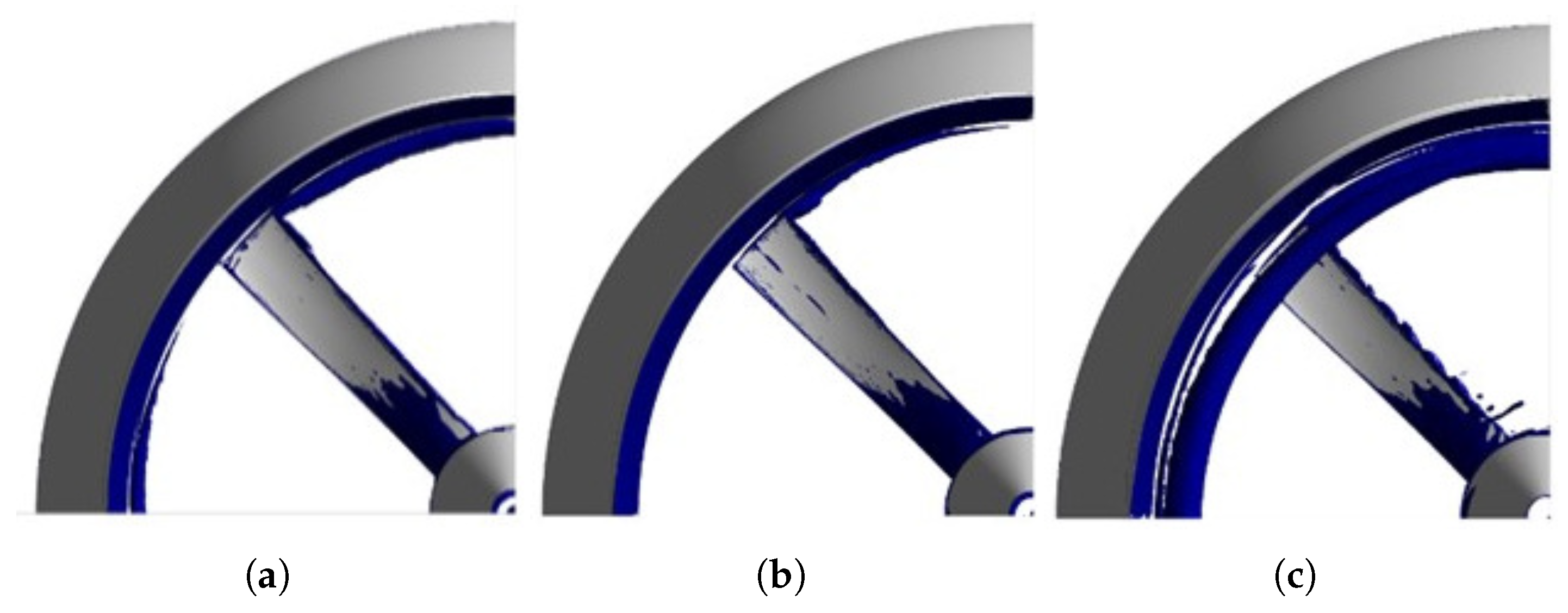
Formation of a vortex core at blade tips with clearances of 0.8% (a), 1.5% (b) and 2% (c). Blade angle of attack is .
At inside the air duct, the flow velocity is distributed uniformly. The change in speed is observed in a local area near the surfaces of the fan blades. With the appearance of a tip clearance, the formation of a vortex end core can be observed. With an increase in clearance size, the formation of a wider, due to the increase in the width of the vortex cell, and a short vortex core is observed. Its small length is explained by more intense dissipation of the vortex core due to an increase in its initial dimensions. Due to the rapid decay of the vortex core, the flow induced by the rotation of the blades can quietly expand in the expanding segment of the air duct located behind the plane of rotation of the fan. This leads to less air deflection when interacting with the blade and the absence of flow separation in the area of the air duct diffuser.
For heavily loaded fans, dependence of the thrust force on h is uncharacteristic. The vortices in this case have transverse dimensions that are significantly larger than the clearance, and a length greater than a quarter of the circle. As a result, the vortices of individual blades feed the vortices of the leading blade, and they merge into one common vortex duct.
At a blade angle of 32 degrees (Figure 13), flow separation from the central body is observed, associated with a large angle of inclination of the root section of the blade relative to the induced flow at a given attack angle. In the axial planes, some inhomogeneity of the velocity field is observed in the space between the blade and the air duct. Near the axis of rotation of the blade, non-uniformity in the velocity field is observed, associated with the general twist of the airflow by the rotating fan. At the wall near the plane of rotation of the fan, a local increase in speed is observed, which is associated with vortices formed at the blade tips. As the clearance width increases, the length of the vortex core of the end bundles becomes noticeably smaller and wider in the region of its origin. An increase in the thickness of the vortex jet leads to its rapid dissipation into the surrounding space. At a clearance width of 2.0%, significant changes in the flow structure occur. A significant increase in the length of the vortex end core is observed. The clearance size, acting as a vortex cell, gives rise to wide and intense vortex end cores. The formation of vortices of similar sizes leads to the interaction of vortex tip wakes from neighbouring blades. They push and feed each other, preventing the vortex core from quickly disintegrating into small-scale chaotic turbulence.
Figure 13.
Formation of vortices on blade tips at clearances of 0.8% (a), 1.5% (b) and 2.0% (c). Blade attack angle is .
The nature of the change in aerodynamic characteristics at different blade attack angles is different. In fact, the thrust graphs when the fans are brought to a single power value reflect the efficiency of the ducted fan design. At a blade angle of 16 degrees, there is a clear optimum. The absence of clearance is the least effective mode of the considered design cases, since in this mode, with a small incident flow on the fan and the considered blade rotation speed (3000 rpm), this angle is not optimal from the point of view of angle of flow on the blade airfoil. In this regard, a large moment of rotational resistance arises on the fan blades, which, when the slightest tip clearance appears, is significantly reduced, improving the efficiency of the ducted fan. This is associated with a local increase in work efficiency. At the same time, with an increase in the clearance size, the intensity of tip vortices decreases. Although the vortices increase in size due to an increase in the size clearance, they dissipate inside the air duct much faster, reducing their contribution to the rotation resistance of the fan. When the clearance reaches a certain value, the influence of the tip vortices becomes not so significant; however, the thrust force of the fan begins to decrease due to a decrease in the length of the working area of the blades, which leads to a general decrease in the efficiency of the blades.
With a blade attack angle of 32 degrees, a slightly different relationship is observed. The angle of flow on the blade airfoil is closer to the optimal one; therefore, the most efficient operating mode without clearance is observed. Despite the significant reduction in thrust without reducing the rotational power to a single power, clearance also significantly relieves the working surfaces of the fan blades, which ultimately leads to the high efficiency of this design. A further increase in the clearance width leads to a deterioration in the efficiency of the fan, since such an expansion of the initial size of the vortex core at an attack angle of 32 degrees does not lead to a significant decrease in the intensity of the vortex core, while the useful area of the working surface of blade decreases. A further increase in the clearance, despite the complex flow pattern, only leads to a decrease in the working area of the blades, due to which the moment and thrust on the blades are reduced, as well as the passing of a noticeable part of the airflow through the clearance, due to which the moment of resistance to rotation also decreases (the necessary drive power).
4. Discussion
The computational results obtained using the SA and SST turbulence models are compared. The SA model does not capture separation at the downstream surface of the blades. The SST model takes into account the effect of a slight increase in thrust due to an increase in the effective thickness of the airfoil. Moreover, both models are applicable to angles of attack without separated flow (for the model blade, this range is from 0 to 25 degrees). Inside the ducted fan, on the surfaces of the duct and blades, there are vast areas with laminar flow, so in calculations it is necessary to use methods that take into account the laminar–turbulent transition.
A study of dependence of operation of a ducted fan on clearance size shows that there is a complex interaction between the flow in the slot and the tip vortices of fan blades. With a moderate load on the fan and an attack angle of the blades of 16 degrees, the optimal clearance is found. It does not make sense to reduce the clearance further, because this does not lead to increased thrust. For the fan considered, this optimal value is equal to 1.5% of the fan diameter. The reason for the presence of an optimum lies in the multi-directional effect of increasing the clearance on thrust loss. On the one hand, an increase in the clearance leads to an increase in thrust losses due to the flow from a high-pressure region to a low-pressure one. With a moderate load on the fan and small clearances, a thin intense vortex is formed, which is slowly eroded by the flow behind the fan, which causes increased vortex losses.
Vortices are formed at the blade tips, the unsteady interaction of which with the underlying surface is important when considering the landing mode of the quadcopter.
Comparison of the moderately loaded () and heavily loaded (, representative of the heavy-load regime 35– identified in the Introduction) regimes shows three qualitatively different features. At the suction-side flow on the blade is largely attached, with at most a thin trailing-edge separation, while at a leading-edge separation bubble is present and grows with the angle; this is reflected in the larger pressure differential between the two surfaces and in the markedly higher torque (Table 1, M rises from 5.7 to 15.9 N m). The tip vortices at have transverse sizes comparable to the clearance h and dissipate within the diffuser. At the tip vortices are much wider than h, neighbouring vortices merge into a circumferential vortex sheet that occupies more than a quarter of the duct circumference (Figure 11, Figure 12 and Figure 13), and the tip-leakage loss saturates around . Consequently, the optimal clearance differs between the two regimes: for vs. (or, technologically, at the cost of a 0.07% thrust loss) for (see Table 2).
In the context of the existing literature, the present results are consistent with the qualitative picture established for ducted propellers [10,11,13]: at low freestream velocity the duct contributes the dominant share of the total thrust, and the tip-leakage flow drives a significant share of the loss budget. Recent parametric studies on duct–rotor coupling for small drones confirm that the tip gap is the dominant geometric parameter governing this trade-off and identify a critical relative gap above which the duct ceases to contribute net thrust [38]. The novelty of the present study is twofold. First, the existence of a non-trivial optimum at constant shaft power (rather than at constant rpm) does not appear to be reported elsewhere for VK-type ducted fans, and runs counter to the common “smaller is better” design rule for tip clearance. Second, the regime where this optimum appears is exactly the regime where the laminar fraction of the boundary layer is large enough that closures without a transition mechanism (SA, plain SST) systematically underpredict the loading.
The interaction of vortical structures with the airframe or propulsor surfaces of an unmanned aerial vehicle (UAV) represents a highly relevant and challenging problem that demands particular attention. Specifically, studies [28,30,33] examine the influence of unsteady propeller flow on UAV airframe surfaces under VTOL conditions, where the proximity of the vehicle to a horizontal surface, or ground plane, plays a critical role. Such problems are essential for the development of safe and reliable control systems and require specialised numerical approaches that rely on scale-resolving turbulence models, such as Large Eddy Simulation (LES), Detached Eddy Simulation (DES), and similar methods.
5. Conclusions
A heavily-loaded VK1-K184V four-blade ducted fan for quadcopter UAV applications has been simulated using the URANS equations closed by the SA and SST turbulence models on an unstructured mesh with near-wall resolution. The main conclusions are as follows.
- In the moderately loaded regime (blade attack angle up to about 25–), both closures predict the experimentally measured characteristic [1] within a few percent. In the heavy-load regime (30–) the SA closure systematically underpredicts the thrust because it does not capture the leading-edge laminar separation bubble. Above the steady RANS framework reaches its applicability limit.
- For the studied configuration, increasing the blade attack angle from 16° to 32° raises the thrust coefficient from 0.27 to 0.84 and the power coefficient from 0.18 to 0.50.
- For the moderately loaded blade (16°) at constant shaft power W, an optimal relative tip clearance of is found, in contrast to the conventional “the smaller, the better” design rule. The optimum results from the competition between the tip-leakage loss (which grows with h) and the dissipation rate of the tip vortices (which also grows with h and reduces the rotational drag).
- For the heavily loaded blade (32°) the maximum thrust is realised at , but the loss at is below 0.1%; the smallest practically realisable clearance therefore suffices.
- Oblique inflow (, 30, ) at freestream velocities up to 75 m/s induces a non-uniform velocity distribution at the duct outlet that affects both axial and circumferential velocity components. The duct contribution to the total thrust dominates at low freestream velocity and drops as grows. The contribution of the air ring prevails only at low flow rates. As the flow rate increases, the ring not only creates excess drag, but also distorts the velocity profile inside the ring, causing different regions of the propeller to operate under different local flow conditions. Increasing the angle reduces the asymmetry of the internal flow in the ring.
Author Contributions
Conceptualisation, P.B.; methodology, P.B.; software, P.B.; validation, P.B.; formal analysis, P.C.; investigation, P.C.; writing—original draft preparation, P.C.; writing—review and editing, P.C.; visualisation, P.C.; supervision, P.B.; project administration, P.B. All authors have read and agreed to the published version of the manuscript.
Funding
This work was financially supported by the Ministry of Science and Higher Education of the Russian Federation during the implementation of the project “Fundamentals of aerodynamics, flight dynamics and control of transport unmanned aerial systems of a new generation with a distributed propulsion system”, №FEFM-2024-0012.
Institutional Review Board Statement
Not applicable.
Informed Consent Statement
Not applicable.
Data Availability Statement
The original contributions presented in this study are included in the article. Further inquiries can be directed to the corresponding author.
Conflicts of Interest
The authors declare no conflicts of interest.
Abbreviations
The following abbreviations are used in this manuscript:
| UAV | Unmanned Aerial Vehicle |
| VTOL | Vertical Take-Off and Landing |
| CFD | Computational Fluid Dynamics |
| NS | Navier–Stokes (Equations) |
| RANS | Reynolds-Averaged Navier–Stokes Model |
| URANS | Unsteady Reynolds-averaged Navier–Stokes Model |
| LES | Large Eddy Simulation |
| DES | Detached Eddy Simulation Model |
| IDDES | Improved Delayed Detached Eddy Simulation |
| SA | Spalart–Allmaras Turbulence Model |
| SST | Shear Stress Transport (k–) Turbulence Model |
| MUSCL | Monotonic Upstream Schemes for Conservation Laws |
| TVD | Total Variation Diminishing |
| GCI | Grid Convergence Index |
| FoM | Figure of Merit |
| PIV | Particle Image Velocimetry |
| RPM | Revolutions Per Minute |
| MRF | Multiple Reference Frame |
Appendix A
To put the present study in context, Table A1 summarises the most relevant prior work, grouped by methodology and by main outcome.
Table A1.
Summary of selected prior studies on ducted fans/shrouded propellers for VTOL and quadcopter UAVs grouped by methodology.
References
- Ostroukhov, S.P. Aerodynamics of Propellers and Propeller Rings; Fizmatlit: Moscow, Russia, 2014. [Google Scholar]
- Buzykin, O.G.; Kazakov, A.V.; Shustov, A.V. Numerical modeling of the aerodynamic characteristics of a small-sized aircraft. Sci. Notes TsAGI 2010, 51, 21–31. [Google Scholar]
- Czyba, R.; Szafranski, G. Control structure impact on the flying performance of the multi-rotor VTOL platform—Design, analysis and experimental validation. Int. J. Adv. Robot. Syst. 2012, 10, 1–9. [Google Scholar] [CrossRef] [Scilit] [PubMed]
- Hrishikeshavan, V.; Chopra, I. Performance, flight testing of shrounded rotor micro air vehicle in edgewise gusts. J. Aircr. 2012, 49, 193–205. [Google Scholar] [CrossRef] [Scilit]
- Nazarov, D.V.; Kondryakova, A.V. Study of flow around a propeller using numerical and experimental methods. Bull. Samara Sci. Cent. Russ. Acad. Sci. 2018, 20, 70–75. [Google Scholar]
- Chovancova, A.; Fico, T.; Chovanec, L.; Hubinsky, P. Mathematical modelling and parameter identification of quadrotor (a survey). Procedia Eng. 2014, 96, 172–181. [Google Scholar] [CrossRef] [Scilit]
- Xiang, X.; Huang, G.; Chen, J.; Li, L.; Lu, W. Numerical investigations of a tip turbine aerodynamic design in a propulsion system for VTO vehicles. Energies 2019, 12, 3003. [Google Scholar] [CrossRef] [Scilit]
- Golovkin, M.A.; Kocish, S.I.; Kritsky, B.S. Methodology for calculating the aerodynamic characteristics of the combined load-bearing system of an aircraft. Proc. Mosc. Aviat. Inst. 2012, 55, 1–16. [Google Scholar]
- Moizykh, E.I.; Zavalov, O.A.; Kuznetsov, A.V. Experimental studies of the aerodynamic characteristics of a remotely piloted aircraft with a rotor-in-a-ring support system. Proc. Mosc. Aviat. Inst. 2012, 50, 1–13. [Google Scholar]
- Akturk, A.; Shavalikul, A.; Camci, C. PIV measurements and computational study of a 5-inch ducted fan for V/STOL UAV applications. In Proceedings of the 47th AIAA Aerospace Sciences Meeting Including The New Horizons Forum and Aerospace Exposition, Orlando, FL, USA, 5–8 January 2009. [Google Scholar]
- Akturk, A.; Camci, C. Experimental and computational assessment of a ducted-fan rotor flow model. J. Aircr. 2012, 49, 885–897. [Google Scholar] [CrossRef] [Scilit]
- Yilmaz, S.; Erdem, D.; Kavsaoglu, M. Effects of duct shape on a ducted propeller performance. In Proceedings of the 51st AIAA Aerospace Sciences Meeting Including the New Horizons Forum and Aerospace Exposition, Grapevine, TX, USA, 7–10 January 2013. [Google Scholar]
- Akturk, A.; Camci, C. Tip clearance investigation of a ducted fan used in VTOL unmanned aerial vehicles. Part I. Baseline experiments and computational validation. J. Turbomach. 2014, 136, 021004. [Google Scholar] [CrossRef] [Scilit]
- Garipova, L.I.; Batrakov, A.S.; Kusyumov, A.N.; Mikhailov, S.A.; Barakos, D. Determination of aerodynamic characteristics of the main rotor model in the axial flow mode. Russ. Aeronaut. 2014, 3, 7–13. [Google Scholar]
- Biava, M.; Barakos, G.N. Optimisation of ducted propellers for hybrid air vehicles using high-fidelity CFD. Aeronaut. J. 2016, 120, 1632–1657. [Google Scholar] [CrossRef] [Scilit]
- Chen, J.; Li, L.; Huang, G.; Xiang, X. Numerical investigations of ducted fan aerodynamic performance with tip-jet. Aerosp. Sci. Technol. 2018, 78, 510–521. [Google Scholar] [CrossRef] [Scilit]
- Xu, H.-Y.; Xing, S.-L.; Ye, Z.-Y. Numerical study of ducted-fan lip stall suppression based on inflatable leading lip cell. Procedia Eng. 2015, 126, 158–162. [Google Scholar] [CrossRef] [Scilit]
- Ohanian, O.J.; Karni, E.D.; Londenberg, W.K.; Gelhausen, P.A.; Inman, D.J. Ducted-fan force and moment control via steady and synthetic jets. J. Aircr. 2011, 48, 514–526. [Google Scholar] [CrossRef] [Scilit]
- Zhang, T.; Barakos, G.N. Review on ducted fans for compound rotorcraft. Aeronaut. J. 2020, 124, 941–974. [Google Scholar] [CrossRef] [Scilit]
- Diisi, F.; Barakos, J.; Kusyumov, A.N.; Kusyumov, S.A.; Mikhailov, S.A. DES modeling of flow around a helicopter rotor. Russ. Aeronaut. 2018, 1, 40–46. [Google Scholar]
- Rumsey, C.L.; Biedron, R.; Farassat, F.; Spence, P. Ducted-fan engine acoustic predictions using a Navier-Stokes code. J. Sound Vib. 1998, 213, 643–664. [Google Scholar] [CrossRef] [Scilit]
- Reboul, G.; Polacsek, C.; Lewy, S.; Heib, S. Aeroacoustic computation of ducted-fan broadband noise using LES data. J. Acoust. Soc. Am. 2008, 123, 3539. [Google Scholar] [CrossRef] [Scilit]
- Rhee, W.; Myers, L.; Mclaughlin, D. Aeroacoustics of vertical lift ducted rotors. In Proceedings of the 15th AIAA/CEAS Aeroacoustics Conference (30th AIAA Aeroacoustics Conference), Miami, FL, USA, 11–13 May 2009. [Google Scholar]
- Astley, R.; Sugimoto, R.; Achunche, I.; Kewin, M.; Mustafi, P.; Deane, E. A review of CAA for fan duct propagation and radiation, with application to liner optimisation. Procedia Eng. 2010, 6, 143–152. [Google Scholar] [CrossRef] [Scilit]
- Malgoezar, A.M.; Vieira, A.; Snellen, M.; Simons, D.G.; Veldhuis, L.L. Experimental characterization of noise radiation from a ducted propeller of an unmanned aerial vehicle. Int. J. Aeroacoust. 2019, 18, 372–391. [Google Scholar] [CrossRef] [Scilit]
- Denisenko, P.V.; Chernyshov, P.S.; Volkov, K.N.; Vokin, L.O. Numerical simulation of the flow around the ducted fan of a quadcopter and determination of its thrust characteristics in various flight modes. Russ. Aeronaut. 2021, 64, 224–232. [Google Scholar] [CrossRef] [Scilit]
- Sun, L.; Liu, X.; Tao, Q.; Yang, J. Aerodynamic performance of ducted fans for large-scale electric propulsion aircraft under variable operating conditions. Phys. Fluids 2025, 37, 035184. [Google Scholar] [CrossRef] [Scilit]
- Denisenko, P.V.; Bulat, P.V.; Chernyshov, P.S.; Volkov, K.N. Aeroacoustic characteristics of the quadcopter propulsion system in vertical take-off and landing mode. Russ. Aeronaut. 2021, 64, 661–669. [Google Scholar] [CrossRef] [Scilit]
- Rybakov, D.V.; Chernyshov, P.S.; Vokin, L.O.; Prodan, N.V. Numerical modeling of vertical landing of an unmanned aerial vehicle with rotor-ring propulsors using eddy-resolving methods. Russ. Aeronaut. 2020, 4, 197–200. [Google Scholar]
- Zhao, Y.; Lian, B.; Zhu, X.; Du, Z. Modal analysis of the unsteady flow dynamics of a ducted fan in the ground effect. Phys. Fluids 2026, 38, 015173. [Google Scholar] [CrossRef] [Scilit]
- Dudnikov, S.Y.; Bulat, M.P.; Vokin, L.O.; Kuznetsov, P.N.; Chernyshov, P.S. Mathematical and computer modeling of single-row and double-row six-blade propeller-ring propulsors. Sci. Tech. Bull. Inf. Technol. Mech. Opt. 2022, 22, 1226–1236. [Google Scholar]
- Bulat, P.V.; Prodan, N.V.; Vokin, L.O. Comparison of Turbulence Models in the Numerical Simulation of the Model Ducted Propeller. Russ. Aeronaut. 2022, 4, 11–21. [Google Scholar] [CrossRef] [Scilit]
- Luo, Y.; Ai, T.; He, Y.; Xu, B.; Qian, Y.; Zhang, Y. Numerical analysis of wind effects on aerodynamic characteristics of a ducted fan. Chin. J. Aeronaut. 2024, 37, 263–280. [Google Scholar] [CrossRef] [Scilit]
- Volkov, K. Numerical analysis of Navier-Stokes equations on unstructured meshes. In Handbook on Navier-Stokes Equations: Theory and Analysis; Nova Science: New York, NY, USA, 2016; pp. 365–442. [Google Scholar]
- Volkov, K. Multigrid and preconditioning techniques in CFD applications. In CFD Techniques and Thermo-Mechanics Applications; Springer International Publishing: Berlin/Heidelberg, Germany, 2018; pp. 83–149. [Google Scholar]
- Spalart, P.R.; Allmaras, S.R. A one-equation turbulence model for aerodynamic flows. In Proceedings of the 30th Aerospace Sciences Meeting and Exhibit, Reno, NV, USA, 6–9 January 1992. [Google Scholar]
- Menter, F.R. Zonal two-equation k–ω turbulence models for aerodynamic flows. In Proceedings of the 23rd Fluid Dynamics, Plasmadynamics, and Lasers Conference, Orlando, FL, USA, 6–9 July 1993. [Google Scholar]
- Wei, W.; Wei, S.; Ke, Z.; Guo, M.; Shu, Y.; Meng, Q.; Jia, L.; Zhang, M.; Han, S. Optimizing the aerodynamic performance of a duct–rotor system for drones: A comprehensive study on the coupled parameters. Drones 2025, 9, 45. [Google Scholar] [CrossRef] [Scilit]

Disclaimer/Publisher’s Note: The statements, opinions and data contained in all publications are solely those of the individual author(s) and contributor(s) and not of MDPI and/or the editor(s). MDPI and/or the editor(s) disclaim responsibility for any injury to people or property resulting from any ideas, methods, instructions or products referred to in the content. |
© 2026 by the authors. Licensee MDPI, Basel, Switzerland. This article is an open access article distributed under the terms and conditions of the Creative Commons Attribution (CC BY) license.