Article

Numerical Investigation of Spray Impingement Heat Transfer in the Film Boiling Regime

by
Mattia Pelosin
1,
Gianluca D’Errico
1,*,
Tommaso Lucchini
1 and
Paolo Albertelli
2,3
1
Department of Energy, Politecnico di Milano, via Lambruschini, 4, 20156 Milan, Lombardy, Italy
2
Department of Mechanical Engineering, Politecnico di Milano, via La Masa, 1, 20156 Milan, Lombardy, Italy
3
MUSP Macchine Utensili Sistemi di Produzione, Strada della Torre della Razza, 29122 Piacenza, Emilia-Romagna, Italy
*
Author to whom correspondence should be addressed.
Fluids 2026, 11(6), 136; https://doi.org/10.3390/fluids11060136

Submission received: 30 April 2026 / Revised: 25 May 2026 / Accepted: 26 May 2026 / Published: 29 May 2026
(This article belongs to the Special Issue Computational Fluid Dynamics of Multiphase Systems)

Abstract

Spray impingement cooling is a well-established heat removal technique employed across a wide range of industrial processes. A particularly significant cooling regime arises when the temperature of the cooled surface surpasses the Leidenfrost temperature of the spray. Developing an accurate numerical framework for this regime holds considerable potential for optimising industrial applications such as cryogenic machining and spray quenching. This paper presents a Eulerian–Lagrangian Conjugate Heat Transfer (CHT) model tailored for spray impingement under Leidenfrost conditions. Two heat transfer sub-models are incorporated to characterise droplet–solid thermal interaction: the first, developed by Breitenbach, is grounded in a theoretical analysis of the droplet impingement process, while the second, proposed by Deb, relies on a semi-empirical correlation. Both models were validated against an experimental correlation obtained from a literature study on orthogonal water spray impingement, yielding mean relative errors of 3.54% for the Deb model and 5.2% for the Breitenbach model across a broad range of operating conditions and surface temperatures.

1. Introduction

Spray cooling of hot surfaces plays a significant role in numerous industrial processes. Notable applications include the quenching of metal components [1], the use of cryogenic cutting fluids in machining operations [2], cryogenic spray systems, and the thermal management of high-power electronic devices. In all these contexts, the rate of heat transfer is of paramount importance: the resulting microstructure of a material is governed by how rapidly it cools, tool longevity is closely tied to cutting temperatures, and the effectiveness of cryogenic machining hinges largely on how efficiently heat is dissipated from the cutting zone [3,4]. The subject is also of considerable interest in the context of internal combustion engines, encompassing fuel injection [5] as well as SCR after-treatment systems, in which the interaction between urea injection and the heated surfaces of mixers [6,7] or wall pipes [8] plays a critical role.
The heat exchanged by the spray depends on the surface temperature and droplet momentum [9]. Below the boiling point, a fraction of the droplet mass typically deposits on the wall, forming a liquid film. Conversely, when the surface temperature significantly exceeds the boiling point, reaching the Leidenfrost temperature, a vapour layer forms between the droplet and the surface [10], preventing wall contact and liquid film formation. This regime, known as film boiling, exhibits a lower heat transfer coefficient compared to conditions where a liquid film is present, such as conduction and nucleate boiling [11] (p. 472). Additionally, droplet momentum governs the post-impingement behaviour, with high droplet velocities promoting droplet break-up.
A substantial body of literature exists on the experimental characterisation of individual droplet kinematics [12] and heat exchange [13] in the film boiling regime, and a range of heat transfer correlations has been proposed for both single droplets and sprays impinging on flat surfaces [14]. Nevertheless, acquiring detailed experimental data for complex, real-world systems remains a considerable challenge. Numerical modelling offers a valuable alternative in this regard, enhancing the understanding of such processes through spray simulation and its capacity to reproduce impinging spray behaviour [15].
To date, simulation studies of spray cooling have predominantly focused on fluid-dynamic aspects [16,17,18], neglecting the thermal response of the solid domain. The absence of a Conjugate Heat Transfer (CHT) framework in such models limits the description of the coupled solid–fluid thermal interaction. A CFD model simultaneously capturing spray dynamics, surface heat transfer, and heat conduction within the solid would enable the systematic investigation of spray characteristics, geometry, and operating conditions, and their mutual interactions, ultimately supporting the optimisation of spray cooling systems. Accordingly, this work aims to investigate this aspect.
In this work, a computational CHT framework was developed and validated for the simulation of spray cooling in the film boiling regime, where the surface temperature exceeds the Leidenfrost point. The spray was represented using an Eulerian–Lagrangian approach, enabling accurate tracking of droplet dynamics and wall interaction. The primary focus of the work was the validation of the heat transfer predictions across a wide range of operating conditions, including varying surface temperatures and mass flow rates, demonstrating the capability of the framework to reliably capture the thermal response of the system under diverse spray cooling configurations. A key contribution of this work was the integration of Lagrangian droplet models within a CHT framework, enabling direct thermodynamic coupling between the dispersed spray phase and the solid domain. Two film boiling heat transfer models were embedded within this Lagrangian description to quantify droplet–wall thermal exchange: those proposed by Deb [14] and Breitenbach [19]. Droplet–wall dynamic interaction was handled through the model of Kuhnke [20]. To close the coupled system, a Dirichlet–Neumann boundary condition was employed at the solid–fluid interface, allowing consistent and simultaneous thermal coupling between the solid, the Lagrangian spray phase, and the surrounding continuous air region.
The consistency of the developed model with respect to mass and energy conservation is first discussed, followed by a validation of the heat transfer coefficient against an experimental correlation formulated by Wendelstorf et al. [21] on the basis of a series of tests involving orthogonal water spray impingement. The choice of this work for model validation stemmed from the large number of tests performed, which enabled an extensive assessment of the model under varying spray operating conditions. The numerical model was found to accurately estimate the total heat transfer, yielding mean relative errors of 3.54% for the Deb et al. [14] model and 5.2% for the Breitenbach model across a broad range of operating conditions and surface temperatures. The variation of the heat transfer coefficient (HTC) with mass flux was well captured, with only a minor deviation observed for very dense sprays. Furthermore, both the Deb and Breitenbach models exhibited sensitivity to wall surface temperature and successfully predicted the increase in heat transfer within the transition region.

2. Materials and Methods

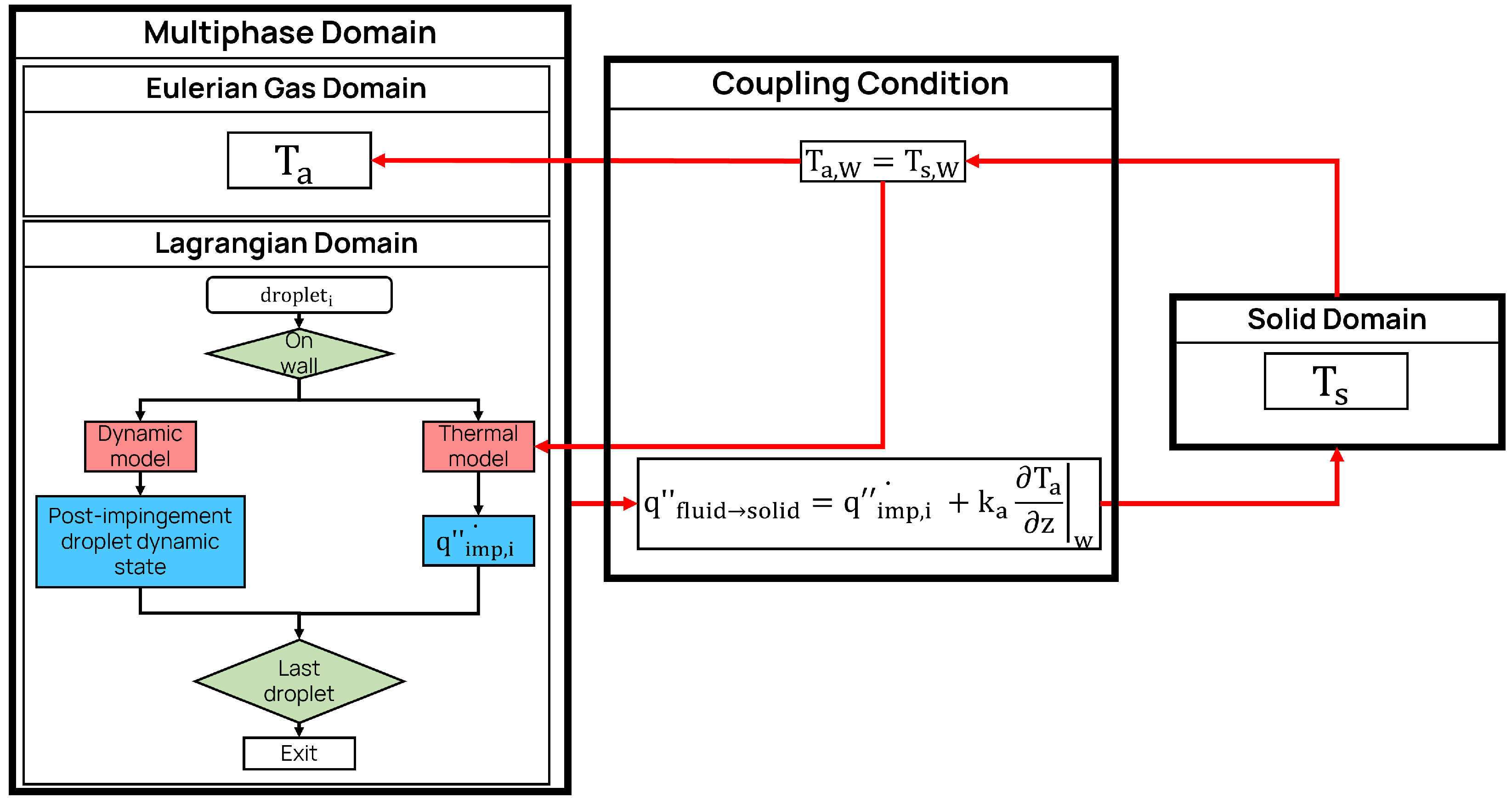
The spray impingement model combines a Eulerian–Lagrangian approach for simulating spray evolution in air with a CHT methodology to capture heat exchange between solid and fluid regions [22], along with an impingement model to assess the thermodynamic phenomena occurring during droplet impact on the wall surface. The model was implemented within the OpenFOAM® framework. The flow diagram shown in Figure 1 illustrates the steps of this model. This section describes the different aspects of this modelling strategy.

2.1. Eulerian–Lagrangian Modelling

The adoption of a Lagrangian approach to modelling sprays eliminates the need to fully resolve the nozzle region within the computational mesh. In this framework, the spray is represented by discrete points, commonly referred to as parcels, which are representative of a group of droplets with the same thermodynamic properties. Each point can be assigned a variety of properties, including location, velocity, diameter, mass, temperature, and liquid composition. These points purely act as markers; hence, they are zero-dimensional and they occupy no physical space in the computational domain. Lagrangian parcels are tracked throughout the computational domain, transitioning between cells according to the governing conservation equations for mass, momentum, and energy, from which the droplet diameter, velocity, and temperature are advanced in time. Coupling with the continuous Eulerian phase is enforced through source terms introduced in the Eulerian transport equations, ensuring conservation of mass, momentum, and energy at the global level. The Eulerian framework resolves the transport equations for continuity, momentum, energy, and turbulence closure, with the additional resolution of n-species mass fraction transport equations to account for the multicomponent nature of the gas phase. For a more detailed description of the equations behind the Eulerian–Lagrangian framework, please refer to Nordin’s work [23].

2.2. Droplet Thermodynamic Impingement

An impingement model was developed for the droplets that impacted the solid wall. If a droplet was close to the wall, this model was applied to determine the post-interaction status (dynamic model) and the heat transfer (heat transfer model). The implemented methodology for the dynamic wall interaction was based on the Kuhnke model [20,24]. Two alternative formulations for the heat exchanged between the droplet and the wall were implemented. A surface field stored the heat exchanged by all the impacting droplets in the considered time step, which was used by the coupling boundary condition to actually perform the heat transfer between the regions.

2.2.1. Droplet–Wall Dynamic Impingement

The Kuhnke model is a semi-empirical framework for droplet–wall interactions, which categorises the possible outcomes into four main regimes: deposition, splash, rebound, and thermal breakup.
  • Deposition occurs at low wall temperatures and low impact velocities and corresponds to the condition in which the droplet adheres to the surface, contributing to the formation of a liquid film;
  • Splash occurs at higher impact velocities but relatively low wall temperatures. In this regime, part of the droplet mass is deposited onto the liquid film, while another portion, due to the high kinetic energy of impact, escapes from the film in the form of secondary small droplets;
  • Rebound happens at low velocities and high temperatures and is basically a quasi-elastic interaction between the droplet and the wall;
  • Thermal break-up happens at high velocities and temperature and represents a disintegration of the impinging droplet into secondary small droplets without film formation.
The classification of the impingement regimes is therefore based on two non-dimensional parameters: one representing the thermal characteristics ( T * ) and the other the dynamic characteristics (K) of the specific impingement phenomenon, as defined in Equation (1):
T * = T w T s a t 1 , K = W e n 1 / 8 L a 5 / 8 ,
where T w is the surface temperature, W e n is the normal Weber number at the impingement state, defined with respect to the droplet velocity component normal to the surface, and L a is the Laplace number, representing the ratio of surface tension to the momentum-transport inside the droplet ( L a = σ ρ D / μ ). Kuhnke defines a deposition limit ( T c r i t * ) beyond which no liquid film formation occurs and, consequently, neither deposition nor splashing can take place. Following the assumption proposed by Birkhold et al., this limit corresponds to the Leidenfrost temperature [20]. Its value typically ranges from 1.1 [25] to 1.43–1.47 [20] times the liquid saturation temperature. Since the regime of interest in this work is above the Leidenfrost temperature, a liquid film would never be formed. For this reason, the developed model does not include a liquid film sub-model. Its validity is therefore limited to T * > T c r i t * and only rebound and thermal break-up interactions are considered.
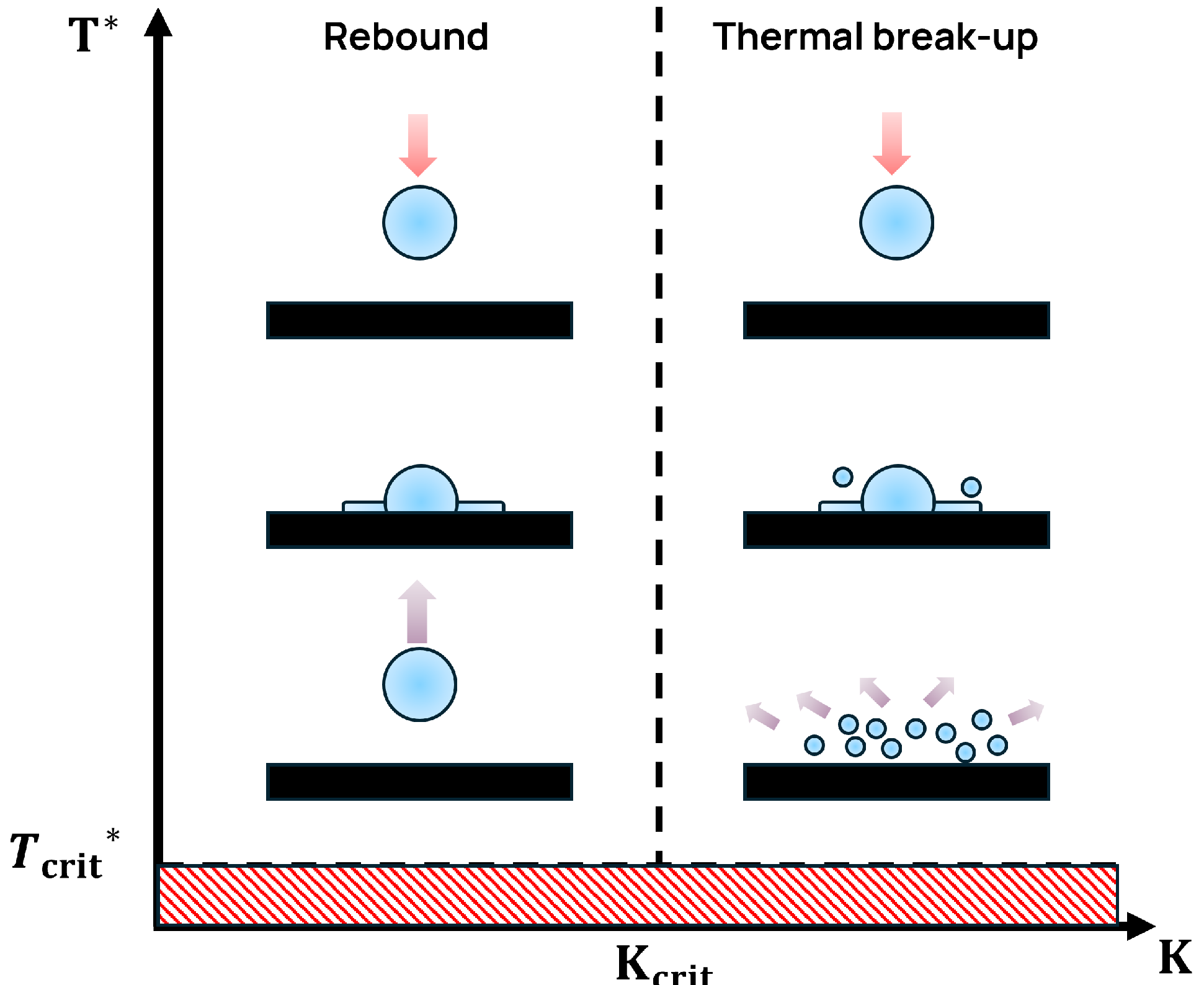
The two impingement regimes of interest are illustrated in Figure 2.
Since both regimes occur above the Leidenfrost temperature, the determining property for their classification is the droplet kinetic energy. A critical value, K c r i t , distinguishes between these two regimes. This parameter is assumed to be independent of surface roughness and is defined as a uniform probability function in the range of 20 to 40 [20,24], to account for the inherent complexity and variability of the phenomenon. In order to fully describe the post-impingement state of the droplets, it is necessary to define both the velocity vector and the droplet diameter. Since no deposition occurs, the droplet mass is conserved during the interaction (apart from the effect of heat transfer at the wall). The following impingement properties must therefore be specified to define the dynamic state of the post-impingement droplet ( d r o p l e t 1 ) relative to the incident droplet ( d r o p l e t 0 ):
  • Size rate:
    γ = d 1 d 0
  • Velocity vector, hence magnitude ( | U 1 | ), ejection angle ( β ) and deviation angle ( φ ).
Rebound
For the rebound interaction, the post-impingement state is straightforward to define, as no secondary droplets are generated; consequently, γ = 1 . A factor U f < 1 is introduced to account for the non-perfectly elastic nature of the impact and the resulting momentum loss during impingement. This factor depends on the impinging Weber number and is defined as follows:
U f = 0.678 e x p ( 4.415 · 10 2 W e 0 ) .
Hence, the exit velocity is:
U 1 = ( 1 2 · U f ) U n , 0 n w + U t , 0 t w ,
where n w and t w are the wall normal and tangential unit vectors and U n , 0 and U t , 0 the corresponding normal and tangential components of the impinging droplet.
Thermal Break-Up
In the thermal break-up interaction, the size ratio is correlated to the Weber number and the impingement angle ( α = a t a n U n , 0 U t , 0 ) as follows:
γ ¯ = 3.3 e 3.6 α π 2 W e 0.65 .
Three parcels are initialised for each impingement event. To assign the size ratio to each of them, a Weibull distribution is employed, centred around the average value γ ¯ . The two parameters defining the distribution, the scale and shape parameters, are set to γ ¯ and 2, respectively. The Weber number of the secondary droplets ( W e 1 ) depends on both the impingement Weber number and the impingement angle. For its determination, the following correlation is employed:
W e 1 = γ W e 0 ( 1 0.85 sin 2 α ) + 12 6 .
The magnitude of the ejected velocity is therefore derived from the computed Weber number:
U 1 = σ W e 1 ρ d i , 1 .
The average ejection angle ( β ¯ ) is correlated as follows to the injection angle and the Weber number:
β ¯ = 0.96 α exp ( 0.0045 W e 0 ) .
A logistic distribution is then used to define the angle for each secondary droplet. The deviation angle ( φ ) is evaluated by the following correlation:
ψ = π ω ln ( 1 p e ω ) with ω = 1 + 8.872 cos 1.152 α 1 cos α , α 80 deg π 2 2 cos α , α > 80 deg
The mass conservation is achieved by relating the number of particles of the secondary droplet to the cube of the size ratio:
n 1 = n 0 γ 3 .

2.2.2. Droplet–Wall Heat Transfer

Once the dynamic behaviour of the impinging droplets has been defined, it is necessary to quantify the heat exchange occurring during impingement. Two alternative models were implemented to evaluate the heat transfer between the wall and the droplets. The Breitenbach model is based on a theoretical description of the orthogonal impingement of a single droplet, whereas the Deb model is an empirically derived correlation. The Breitenbach model is discussed in greater detail below to provide a clearer understanding of the underlying physical mechanisms governing this phenomenon.
Breitenbach Model
The model proposed by Jan Breitenbach et al. [19] is based on a theoretical analysis of the emergence and expansion of the thermal boundary layers in an orthogonal impingement of a single droplet. The heat transfer during the spreading of the drop is analysed considering the thermal interaction with the solid substrate and the creation of the vapour layer.
The model is developed based on the hypothesis of a droplet impacting a flat solid surface in the fully developed film boiling regime (Leidenfrost interaction). Under this assumption, a vapour film forms between the liquid and the solid surface due to rapid evaporation. A one-dimensional approximation in the direction orthogonal to the surface is employed, since the film thickness is much smaller than the droplet diameter.
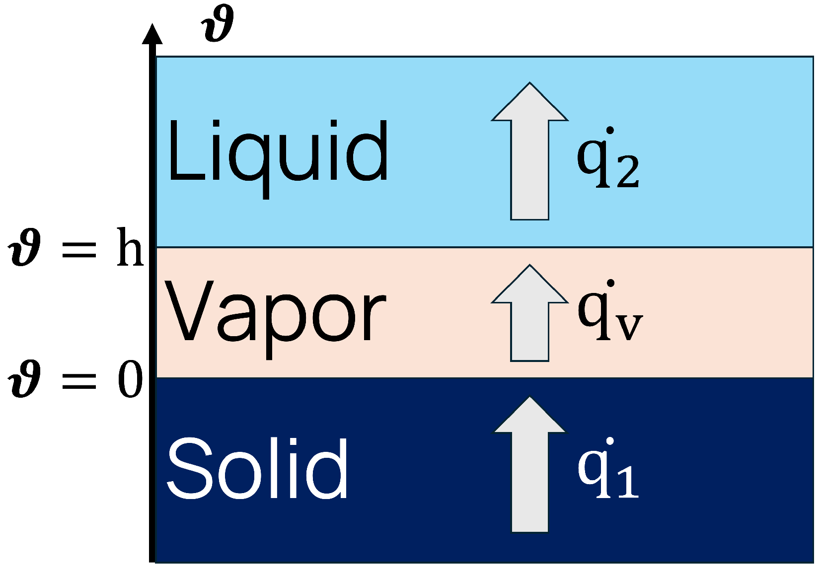
The energy balance of the liquid–vapour layer–solid system, represented in Figure 3, is written as:
q ˙ 1 = q ˙ 2 + ρ l h l v d h d t ,
where q ˙ 1 is the heat exchanged from the solid to the vapour, which equals the the heat exchanged from the vapour to the liquid q ˙ 2 plus the phase change contribution, defined as the product of the time derivative of the vapour layer height ( d h d t ) and the latent heat of evaporation ρ l h l v d h d t . The solution of the energy balance equation in the spreading droplet is written as:
T l ( θ , t ) = T sat + ( T D 0 T sat ) erf 5 θ 2 α t ,
where θ is the orthogonal coordinate to the surface and α is the liquid thermal diffusivity. Note that at θ = 0 the liquid temperature is the saturation temperature since it is at the vapour interface, and hence it is where the phase change occurs. It is now possible to define the heat flux at the liquid/vapour interface as:
q ˙ 2 ( t ) λ f T f θ θ = h = 5 e f ( T sat T D 0 ) π t ,
where e f is the liquid thermal effusivity. Similarly, the heat flux at the solid–vapour interface is:
q ˙ l ( t ) λ w T w θ θ = 0 = e w ( T 0 T c ) π t ,
During the initial spreading of the droplet, the pressure within the liquid is dominated by inertial forces. In this stage, the formation of the vapour film is primarily governed by heat transfer from the liquid and solid substrates.
Since heat transfer between the wall and the droplet is inversely proportional to the vapour layer thickness, most heat is transferred during the early stage of impact, when the vapour thickness is minimum. The heat flux density of an impacting single droplet in the film boiling regime can be calculated as:
q ˙ 1 ( t ) = 2 G e w ( T 0 T sat ) π ( K + 2 G ) t ,
where e w is the solid effusivity and K and G are two parameter functions of the system’s physical properties. Hence, the total heat removed by a single impacting drop during the initial stage t i is the time integral of the product of the one-dimensional heat flux and the impingement area, and, after various mathematical steps, it takes the following form, Equation (15):
Q d = 4.63 G D d 5 / 2 e s ( T w T s a t ) U d , n ( K + 2 G ) ,
The hypothesis of an orthogonal impingement of a single droplet is hardly ever the case for spray droplets. To generalise the model to a random impingement, only the magnitude of the velocity component normal to the surface has been considered in the formulation. This is a common choice in the literature ([12,13,26,27]), because heat transfer is determined by the spreading of the droplet on the surface and by the contact time. Both these aspects are driven by the normal momentum.
Deb Model
The semi-empirical correlation proposed by Deb [14] is based on experimental data available in the literature for the impingement of a stream of droplets. This model does not directly define the heat exchanged; instead, it is based on the definition of the droplet heat transfer effectiveness ( ϵ ). This parameter represents the ratio between the actual heat transferred to the wall and the total heat stored in the droplet (Equation (16)):
ϵ = Q d m d [ Δ h + C p , l ( T s a t T l ) ] ,
where m d is the droplet mass, Δ h is the latent heat of vaporization and C p the heat capacity. To quantify ϵ , dimensional analysis was applied, and the following non-dimensional parameters were defined:
W e n = ρ d U d , n 2 / σ , B = C p , v ( T w T s a t ) / Δ h , K d = k v μ v C p v , S F = e s e s t 1 .
where W e n is the normal Weber number, B is the wall superheat parameter, K d is the vapour parameter, and S F is the surface material parameter, which is referenced to the steel thermal effusivity e s t = k s t C p s t ρ s t . A statistical analysis was carried out, and the correlation presented in Equation (18) was obtained:
ϵ = 0.027 e x p 0.08 ln ( W e n / 35 + 1 ) ( B + S F / 60.5 ) 1.5 + 0.21 K d B e x p 90 W e n + 1 .
The final model for the droplet heat transfer in the spray condition is shown in Equation (19):
Q d , s p r a y = X · Q d .
Here, X is a fitting parameter used to match model predictions to the prediction of the Wendelstorf correlation. The coefficient was introduced by Breitenbach to reflect the fact that the model accounts for heat transfer only during the initial impact stage, when the vapour gap is at its thinnest and vapour growth is governed by heat transfer, while the later spreading stage is disregarded. This simplification is physically grounded, since heat flux density drops sharply over time, making the contribution of the late spreading stage negligible; values of X near unity are therefore considered acceptable [19]. Conversely, Deb [14] did not include such a coefficient; however, due to the inherent complexity of the impingement phenomenon, significant scatter has been observed among different experimental studies. Consequently, a correction coefficient was also applied to the Deb model to fit the predicted heat transfer to the Wendelstorf correlation. The coefficient was calibrated against a single operating condition and kept constant throughout the entire simulation campaign, ensuring that the model response reflected genuine sensitivity to varying operating conditions rather than parameter adjustment.

2.3. Multiphase–Solid CHT Coupling

The coupling between the solid and fluid regions is performed within the CHT framework. CHT is a simulation methodology that enables the simultaneous analysis of regions governed by different physical phenomena—in this case, fluid and solid domains. The coupling between these regions is achieved through a boundary condition that resolves the heat transfer at their interface. In the case of spray impingement, heat exchange occurs across both the droplet–solid and air–solid interfaces; therefore, a dedicated boundary condition was implemented to accurately account for these combined effects.
At the interface, in the case without spray cooling, two conditions must be satisfied, namely the continuity of temperature and the energy conservation (Fourier Law for heat conduction). The following system of equations can be written:
T a , w = T s , w k a T a n | w = k s T s n | w .
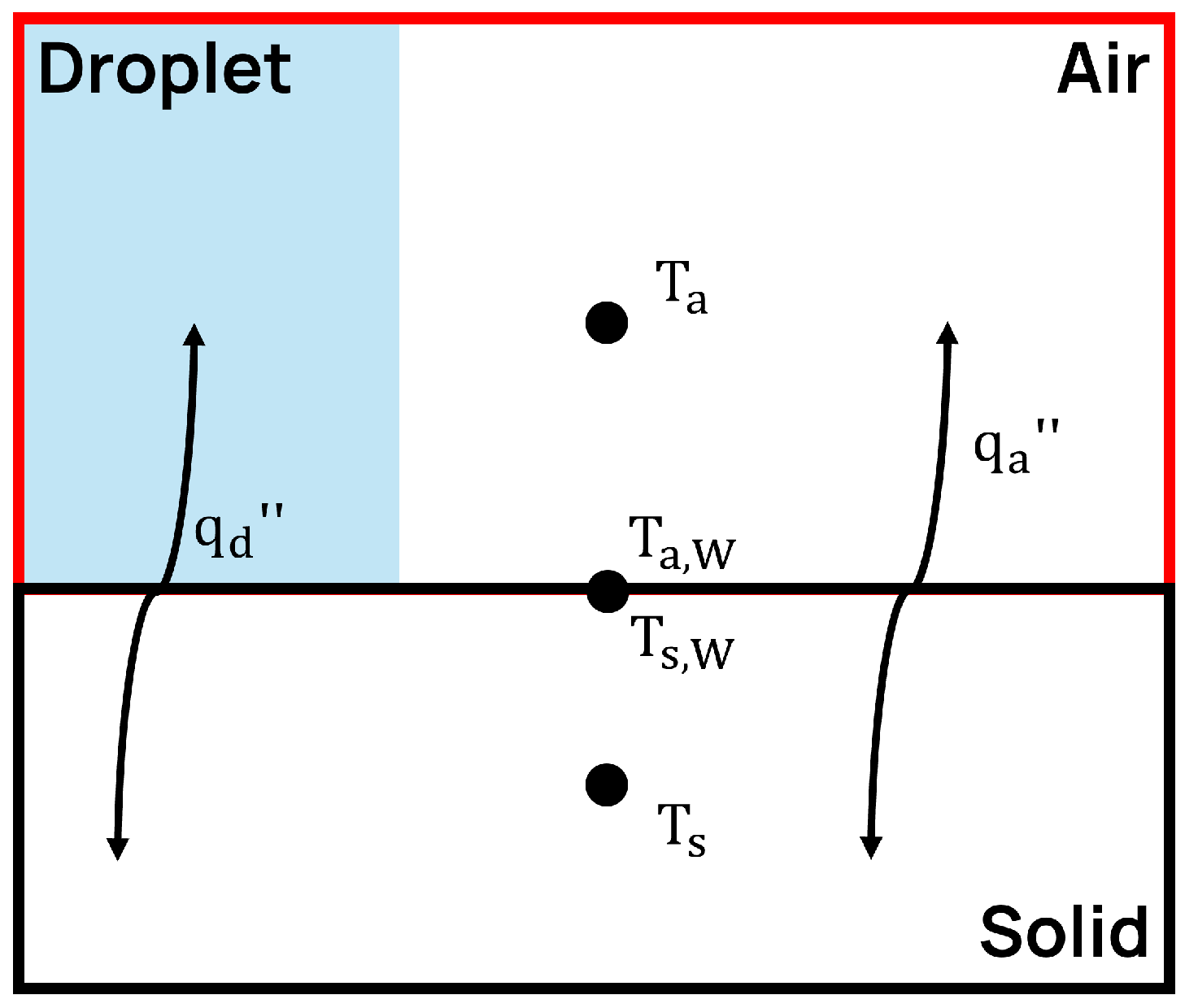
In which T a , w is the wall temperature on the fluid side and T s , w the wall temperature on the solid side. This system can be solved through two approaches. The first consists of applying the Fourier law on both sides of the interface. The second relies on a Dirichlet–Neumann coupling, where the temperature is imposed on one side and the heat flux on the other. The former represents the standard approach in OpenFOAM, as it requires no user specification regarding the boundary condition assignment on each side. During spray impingement, the heat flux on the surface of each solid boundary face ( q s ) consists of two contributions: the convective heat transfer with the gaseous region ( q a ) and the heat exchange between the solid and the impacting droplets ( q d ) (Figure 4).
Under the hypothesis of a dimensionless dispersed phase, consistent with the Lagrangian framework, the system of equations is modified. While temperature continuity between the Eulerian gaseous phase and the solid region is still enforced, an additional heat transfer contribution on the solid side arising from the impinging droplets must be accounted for:
T a , w = T s , w k a T a n | w + q d = k s T s n | w .
This condition renders the standard OpenFOAM procedure of solving the Fourier equation on both sides of the interface unsuitable, since the heat transfer is no longer balanced between the Eulerian gaseous phase and the solid region. As a result, the boundary condition employed in this work is based on a Dirichlet–Neumann coupling approach, in which the heat flux is enforced on the solid side of the interface while the temperature is imposed on the gaseous side.

2.4. Validation Case

The impingement model was validated against an experimental correlation obtained from a study on orthogonal water spray impingement conducted by Wendelstorf et al. [21]. This analysis was performed to evaluate the performance of the droplet–wall heat transfer models under varying conditions of mass flux and wall temperature.
The main validation parameter was the surface heat transfer coefficient, defined in Equation (22):
H T C = q w T w T s p r a y ,
where q w and T w are the surface heat flux and temperature, while T s p r a y is the droplet temperature.

2.4.1. Experimental Set-Up

According to the authors [21], the experimental tests were conducted employing three full-cone nozzles (Spraying Systems VKE6/60, VKE6/90, and VKE8/60) at nozzle-to-sample distances ranging from 62 to 105 mm. The test specimens consisted of 1.0 mm-thick discs made from commercially pure nickel with a diameter of 70 mm. To measure the heat transfer coefficient (HTC), five thermocouple pairs were welded to the underside of each disc, equally spaced starting from the centre and moving radially every 10 mm. The droplet velocity and size distributions were estimated from empirical correlations [28], and for the investigated spray conditions the average droplet velocity was found to lie between 13 and 15 m/s, with mean droplet diameters in the range of 300–400 µm. Twenty-eight experiments were performed with a water temperature of T l = 291 K, water mass flux densities ( V s ) varying from 3 to 30 kg / ( m 2 s ) and temperature differences between the wall and the droplet ranging from 150 to 1100 K. The mass–flux density was proportional to the ratio between the mass flow rate and the impinging area ( V s = m s ˙ A i m p ).
The following analytical correlation for the dependence of heat transfer dependency on the wall temperature and the mass flux was then proposed (Equation (23)), with ± values indicating the 95% confidence intervals:
H T C = 190 ± 25 + tanh V s 8 · 140 ± 4 V s 1 V s Δ T 72000 ± 3500 + 3.26 ± 0.16 Δ T 2 1 tanh Δ T 128 ± 1.6
where Δ T = T w T l is the difference between the wall surface temperature and spray temperature. The correlation remained valid over the full range of conditions examined experimentally, covering V s = 3–30 kg / ( m 2 s ) and wall temperature from 473 K to 1373 K.

2.4.2. Simulation Set-Up

Nine simulations were performed for validation purposes, varying the wall temperature and mass flow rate. The corresponding operating conditions are summarised in Table 1. The solid sample temperatures were selected to ensure operation well within the fully developed film boiling regime, with a sufficient margin above the Leidenfrost point. As discussed in Section 2.2.1, the Leidenfrost temperature for water at ambient pressure lies between 1.1 and 1.47 times the saturation temperature, corresponding to T w = 410–548 K. Taking the upper bound as a conservative estimate, all the validation cases were conducted at wall temperatures well above this threshold, the lowest being T w = 791 K, thereby guaranteeing the complete absence of liquid film deposition and confirming that the entire validation campaign fell within the applicability range of the proposed model. As regards V s , the range was chosen to cover the transition between dilute and dense sprays.
The spray was simulated using a cone injection model. The parcels were introduced in the domain at the nozzle position, with a fixed velocity (14 m/s) and a random direction limited by the characteristic cone angle of the spray (60 deg). Droplet diameters were initialised based on the Rosin–Rammler mass distribution [29] with a minimum of 300 μ m , a maximum of 400 μ m and an average of 350 μ m .
The fluid domain was a box of 150 mm × 150 mm and 100 mm along the spray axis, while the solid domain was 150 mm × 150 mm and 1 mm, matching the real disk thickness. The computational mesh was fully hexahedral.
The mesh configuration consisted of 225,000 cells for the solid region and 112,500 for the fluid region; the mesh resolution was 0.1 mm for the solid region and 2 mm for the fluid region.
Since the validation was performed in steady-state conditions, the temperature profile along the normal direction was linear and, therefore, substantially insensitive to the mesh resolution of the solid region.
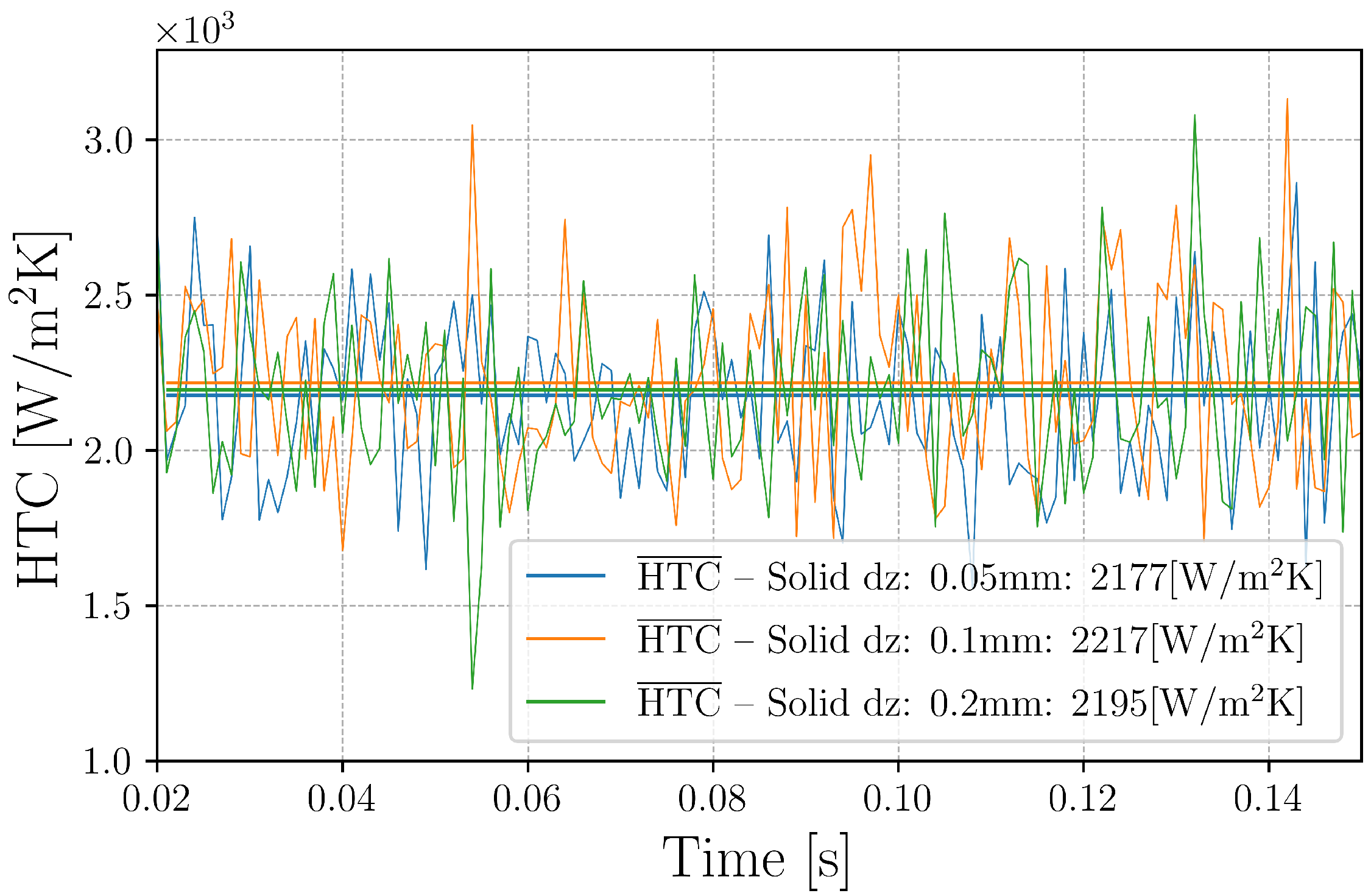
To verify solid domain mesh independence, the same operating condition ( V s = 15 kg / m 2 s , Δ T = 700 K) was simulated on two additional solid meshes with wall-normal resolutions of 0.2 mm (coarse) and 0.1 mm (fine). The HTC results, shown in Figure 5, confirm that the heat transfer coefficient was insensitive to the solid mesh resolution, with a difference of the estimation of the average HTC close to 1%.
The dimension of the wall layer in the fluid region is less critical with respect to standard single-phase simulations, since the majority of the energy transferred is due to the droplet impingement, which is modelled as a marker, and hence their properties do not depend directly on the dimension of the mesh.
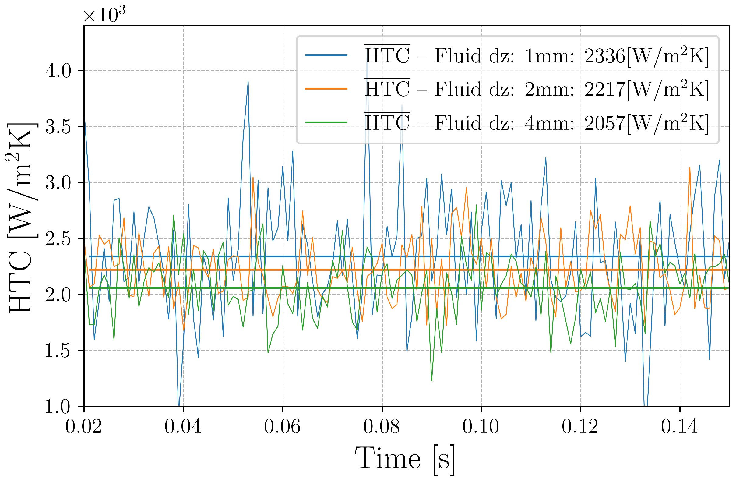
To support this statement, mesh sensitivity in the fluid wall-layer was assessed by simulating two additional wall-normal resolutions: 4 mm (coarse) and 1 mm (fine). The HTC results in Figure 6 indicate a modest mesh dependence, with the average HTC differing by approximately 5% between the base and fine meshes. Given the complexity of the system under investigation, the base mesh was selected for the remaining validation cases as a balance between computational efficiency and solution accuracy. It is also worth noting that finer meshes were found to limit the solver stability, as the sharp local gradients arising at the droplet impingement locations imposed a significantly reduced time step.
Regarding the simulation set-up, the PIMPLE resolution algorithm was used, with two internal pressure correctors and two outer correctors. The Euler implicit time scheme was used for time discretisation, and second-order limited schemes were used for divergence and Laplacian discretisation. A time step of Δ t = 1 × 10 4 s was selected to maintain a Courant number of approximately 0.6, ensuring sufficient temporal accuracy of the numerical solution. Turbulence was treated in RANS fashion, and the well-known k- ε model was employed [15]. Standard OpenFOAM wall functions, namely kqRWallFunction, epsilonWallFunction and compressible:alphatWallFunction, were applied at the wall boundaries to model the turbulent kinetic energy, dissipation rate and turbulent thermal diffusivity, respectively. The final fluid mesh consisted of uniform cubic cells, yielding a near-wall resolution of 2 mm. The standard k- ε model has known limitations in accurately predicting impingement flows. Nevertheless, within the present Eulerian–Lagrangian framework, the impinging liquid phase plays the dominant role in the near-wall dynamics and associated heat transfer processes. As a result, the overall solution is primarily governed by the spray behaviour and interaction mechanisms, which reduces the sensitivity of the predicted thermal response to the specific turbulence closure adopted for the gas phase.
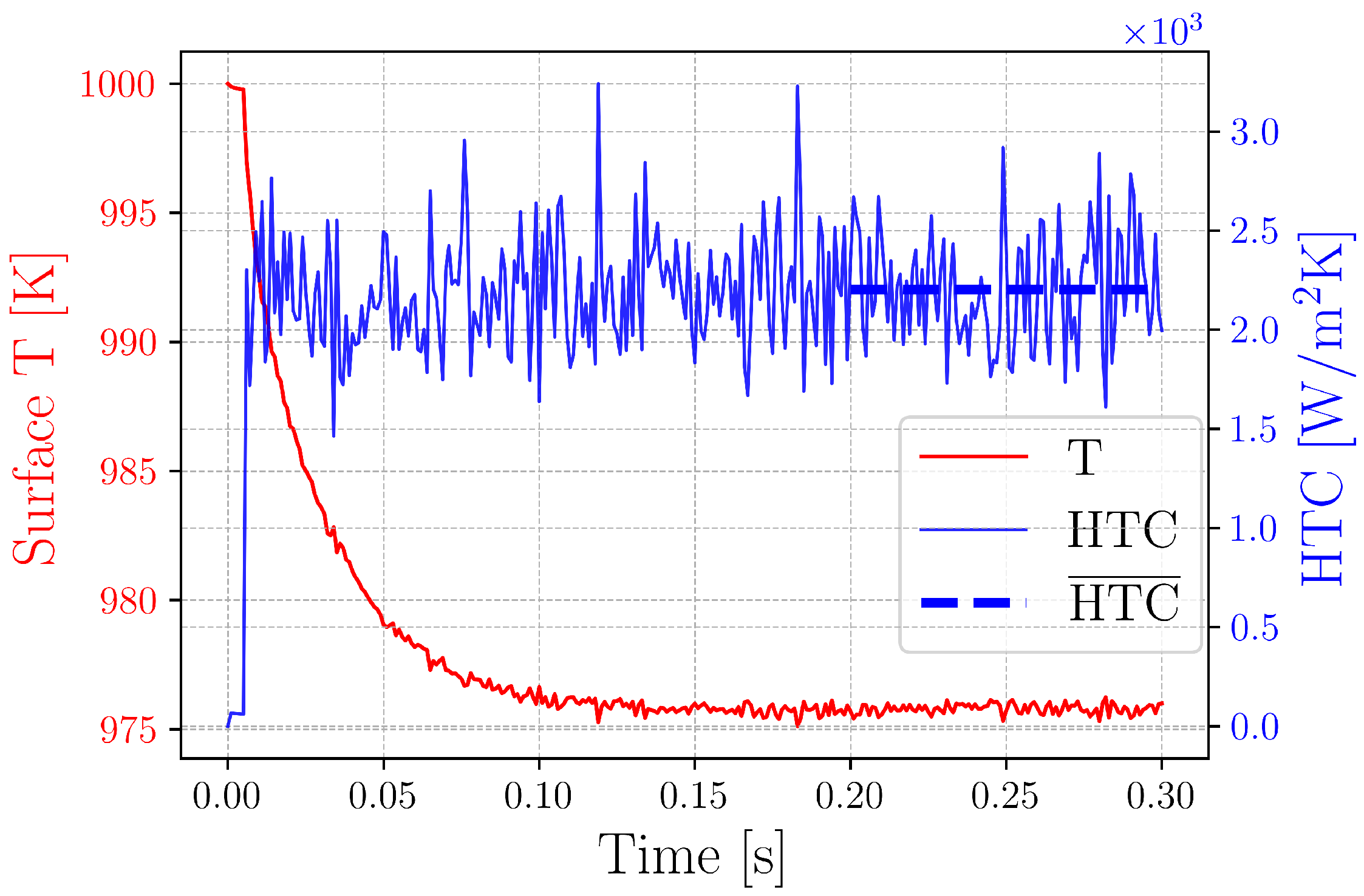
Adiabatic boundary conditions were applied to the lateral patches of the solid disk, while the bottom face was maintained at a constant temperature equal to the initial condition. This configuration was adopted to enable direct comparison with experimental data during post-processing. Fixing the bottom temperature drove the system towards a steady-state solution, at which point the HTC was computed. Figure 7 reports the temporal evolution of the average solid surface properties in the impingement region for the case V s = 15 kg / m 2 s and Δ T = 700 K . The surface temperature reached steady-state conditions after 0.15 s. Accordingly, the HTC was computed as a time-average from this instant to the end of the simulation, which was fixed at 0.3 s for all the investigated cases. The observed fluctuations in the HTC are ascribed to the stochastic variation in the number of droplets impinging on the surface at each time step.

3. Results

The results section is structured into two distinct parts. The first focuses on a detailed characterisation of the thermodynamic state of the system under a reference operating condition, defined as V s = 15 kg / m 2 s and Δ T = 700 K . The second addresses the validation of the proposed methodology over the entire range of the operating conditions considered.

3.1. Thermo-Dynamical Analysis of the Impingement Process

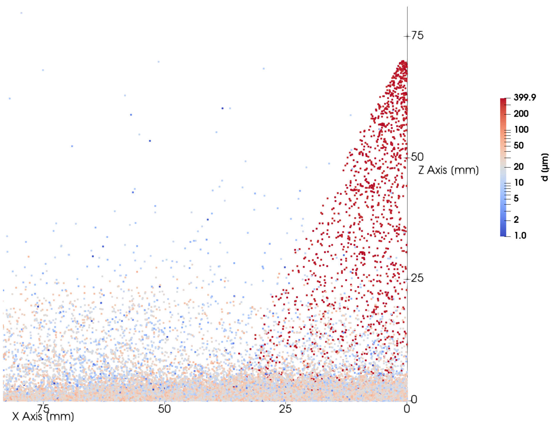
Figure 8 shows the evolution of the droplets’ diameter during the impingement process.
The droplet diameter remained largely unchanged during the flight phase, indicating negligible evaporation before wall interaction. Upon impingement, the droplets underwent thermal break-up, with the post-impingement diameter reducing significantly from a pre-impact average of 350 μ m to values below 50 μ m . This fragmentation occurred because for this specific spray configuration the droplets were characterised by a kinetic non-dimensional number (K) greater than the critical value ( K c r i t ).
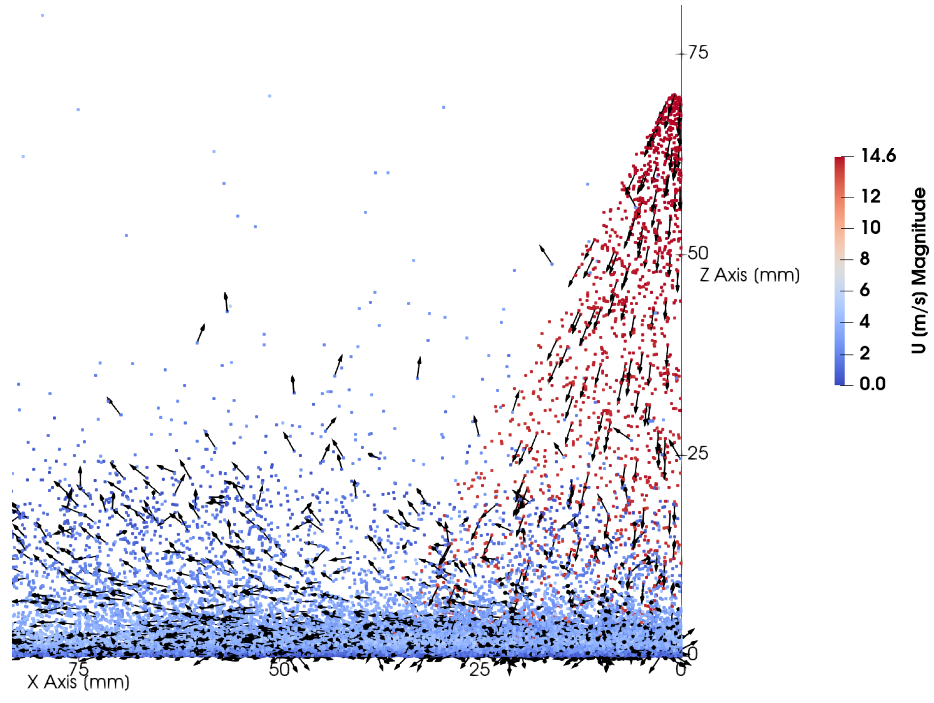
As shown in Figure 9, thermal break-up resulted in a significant reduction of the secondary droplet velocity magnitude, consistent with the dissipative nature of the splashing process. Upon wall interaction, the wall-normal momentum was almost entirely absorbed at impact, constraining the motion of the secondary droplets to a predominantly wall-tangential direction. This behaviour was further reinforced by the reduced inertia of the smaller post-impingement droplets, which made them more susceptible to aerodynamic drag, causing their trajectories to progressively align with the radial flow field induced by the impingement jet.
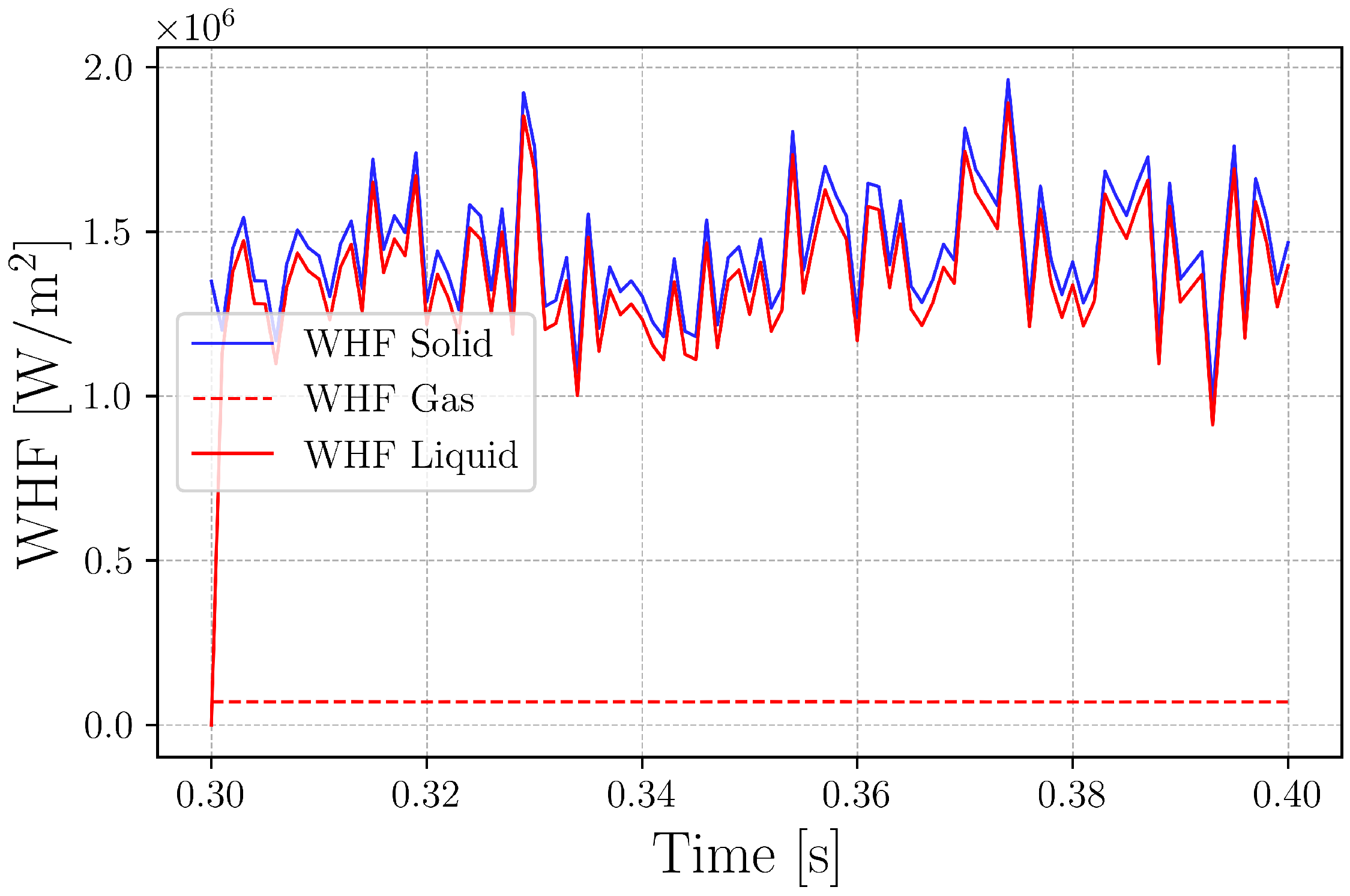
Focusing on the heat transfer at the solid–fluid interface, Figure 10 illustrates the evolution of the heat flux within the impingement area under steady-state conditions. With reference to Equation (20), three heat transfer contributions can be distinguished:
  • On the solid side, heat was transferred by conduction: W H F S o l i d = k s T s n | w ;
  • On the gaseous side, within the Eulerian domain, heat exchange with the solid took place through convection: W H F G a s = k a T a n | w ;
  • On the Lagrangian side, the heat transfer corresponded to the cumulative contribution of the droplets impinging on the surface at each time step: W H F L i q u i d = Q d , i / Δ T .
As anticipated, direct droplet impingement constituted the dominant heat transfer mechanism, corroborating the point-particle assumption. Moreover, the sum of W H F G a s and W H F L i q u i d was found to equal W H F S o l i d , thereby ensuring energy conservation at the solid–fluid interface.
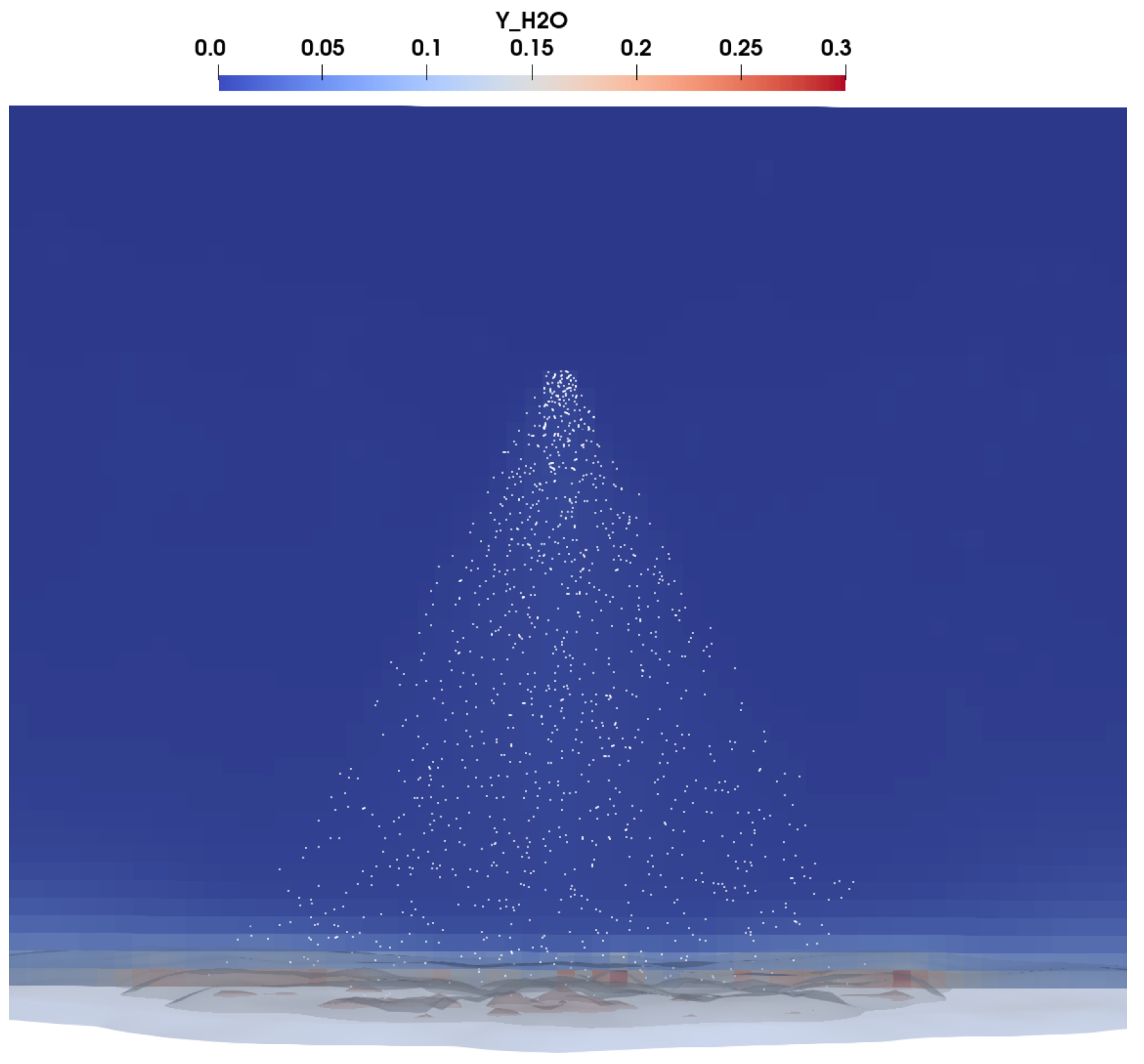
Concerning the phase change of the dispersed phase, evaporation occurred predominantly at the impingement zone, since the spray propagated through a nearly isothermal environment before reaching the wall. Moreover, as a consequence of the Leidenfrost phenomenon, the heat exchanged between the impinging droplets and the wall directly induced phase change, driven by the formation of a vapour cushion at the liquid–solid interface.
Figure 11 confirms this behaviour, showing that the region of highest water mass fraction—corresponding to the evaporated dispersed phase—was concentrated in the cells closest to the wall, while the water mass fraction was nearly negligible further away from the impact zone.
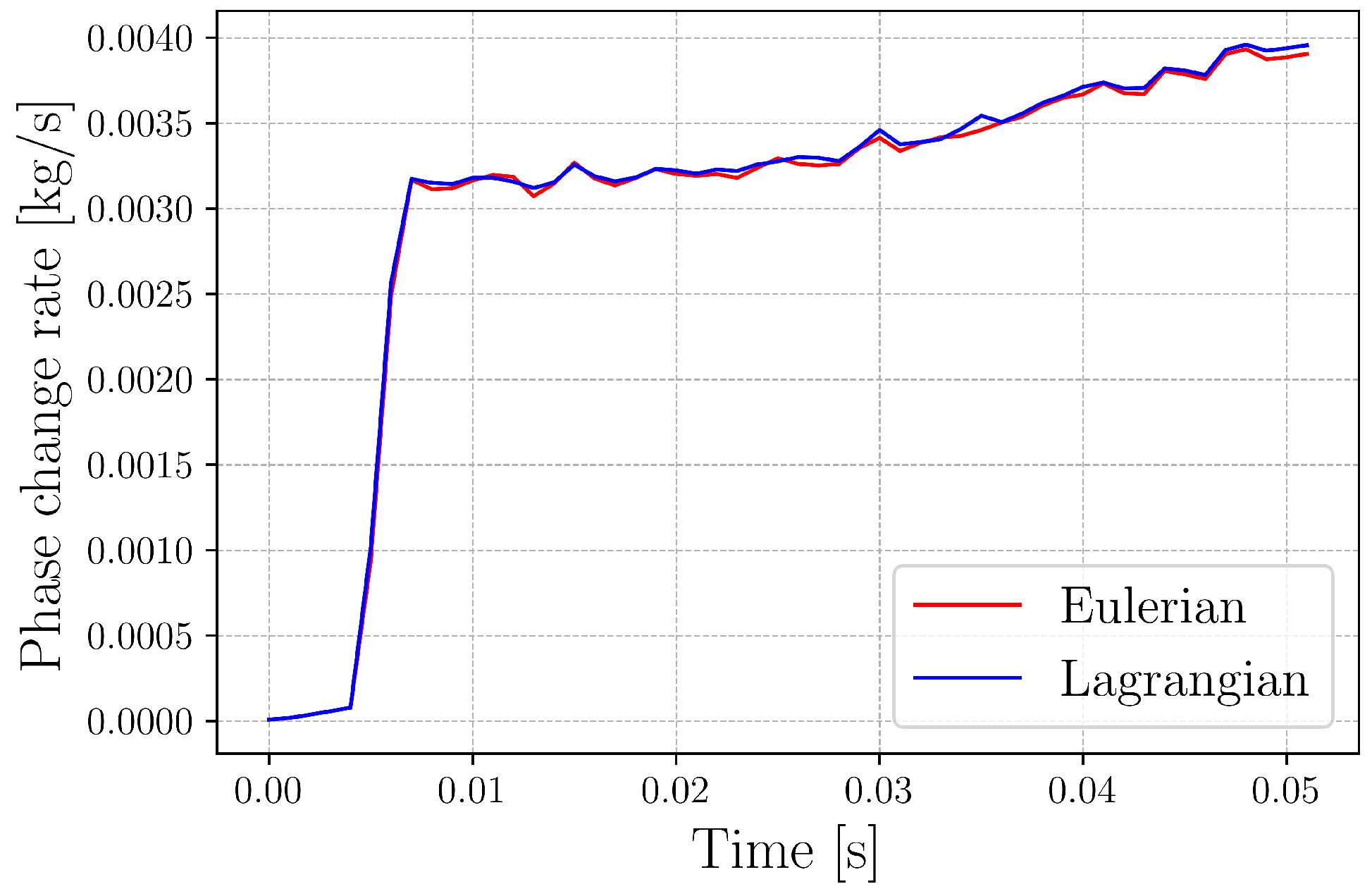
Figure 12 provides a quantitative description of the phase change process, evaluated both in the Eulerian domain by integrating the product of density and water mass fraction and in the Lagrangian domain by computing the difference between the injected and current Lagrangian mass in the domain. The mass transfer rate increased sharply when the first droplets contacted the wall, approximately 0.008 s after the start of injection, and it continued to rise thereafter. This is partly attributable to the post-impingement droplets, which exhibited a smaller diameter and thus a larger surface-to-volume ratio, resulting in an enhanced phase change rate. Additionally, the agreement between the mass transfer rates computed in both domains confirms the mass conservation of the proposed approach.

3.2. Validation

This section presents the results of the simulation campaign conducted across the operating conditions defined in Table 1. For each case, the heat transfer coefficient is computed and its trend is discussed.
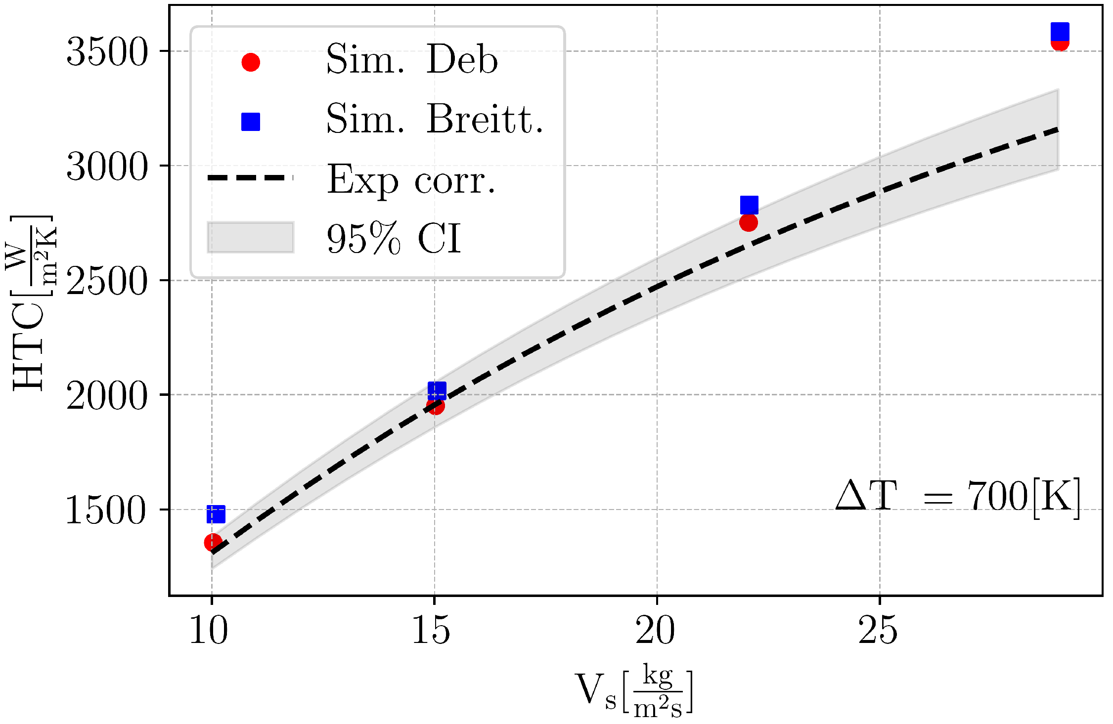
The influence of the mass flux on the heat transfer is shown in Figure 13. The simulations demonstrated a satisfactory agreement with the Wendelstorf correlation across most of the investigated conditions, with an average relative error of 4.76% for the simulation with the Deb model and 8.61% for the the Breitenbach model. The heat transfer increased sub-linearly with V s , due to the non-linear dependency of the thermal impingement models (Equations (15) and (18)) on the impact velocity. The largest discrepancies were observed under the densest spray conditions, where droplet–droplet interaction limited the net heat transfer contribution of each individual droplet. In such configurations, the spatial and temporal proximity of successive impacts gives rise to overlapping zones of influence, reducing the effective heat transfer per droplet. Upon impact, each droplet flattens into a disk under the action of its incoming kinetic energy, and then contracts, either bouncing or shattering depending on the balance between inertial and surface tension forces (rebound or thermal break-up interaction). This process generates two distinct zones of influence around each impact site: a hydrodynamic zone, arising from the radial spreading motion along the wall, and a thermal zone, originating from the localised temperature decrease induced in the solid upon contact. Each zone is characterised by a maximum diameter of influence and a characteristic interaction timescale. As droplet number density increases, the overlap between these zones becomes significant, such that the solid surface in the vicinity of each impact site is already thermally and hydrodynamically disturbed prior to the arrival of subsequent droplets, thereby reducing the available temperature gradient and the associated heat transfer rate [14]. Breitenbach proposed a correction to the droplet heat transfer to account for dense spray effects, expressed as a function of the mass flux density V s . This correction was not adopted in the present work, as the mass flux density requires knowledge of the impingement area, which cannot be unambiguously defined in a realistic spray cooling configuration, limiting the applicability of this correction.
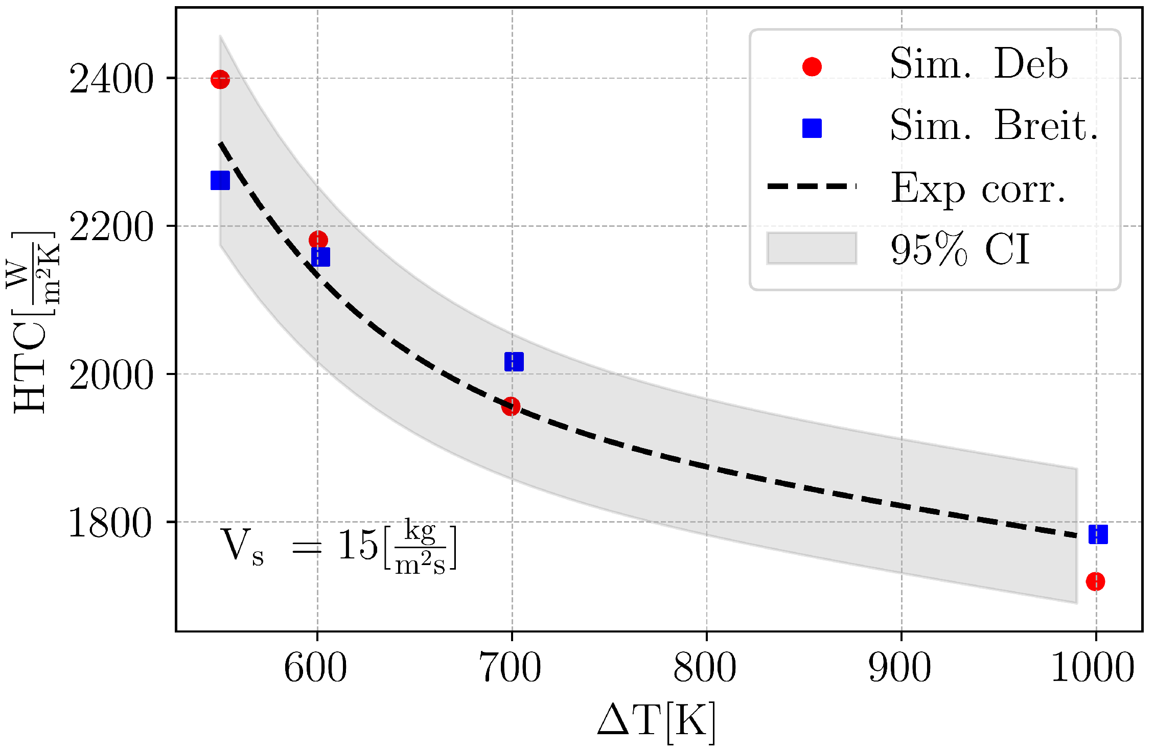
The effect of wall surface temperature on heat transfer is shown in Figure 14. Both the Deb and Breitenbach models were sensitive to wall temperature and showed a significant increase in HTC in the transient regime (smaller Δ T ), with an average relative error of 2.32% for the simulation with the Deb model and 1.78% for the Breitenbach model. The Breitenbach model yielded superior agreement with the Wendelstorf correlation in the fully developed film boiling regime, whereas the Deb model performed better in the transitional regime. This difference in predictive accuracy can be attributed to the distinct foundations of the two models. The Breitenbach model is derived from a theoretical analysis strictly valid within the film boiling regime; consequently, its underlying assumptions progressively break down as conditions approach the transitional regime. The Deb model, by contrast, is based on empirically derived correlations that inherently encompass the transitional regime within their experimental basis, preserving their validity across a broader range of thermal conditions.
The statistics of the validation performed are summarized in Table 2.
The fitting parameter (X in Equation (19)) was set to 3.2 for the Breitenbach model and 0.3 for the Deb model across all the simulated cases. The value adopted for the Breitenbach model was in close agreement with that reported by the original authors under comparable conditions, suggesting that the present simulations were consistent with their findings. As noted by Breitenbach, the proximity of this value to unity implies that the model correctly captures the dominant physical mechanisms governing heat transfer in an impacting droplet. The Deb model coefficient, by contrast, deviates significantly from unity. Despite this correction, both fitting parameters were kept constant throughout the entire simulation campaign to assess the sensitivity of each model to varying operating conditions.
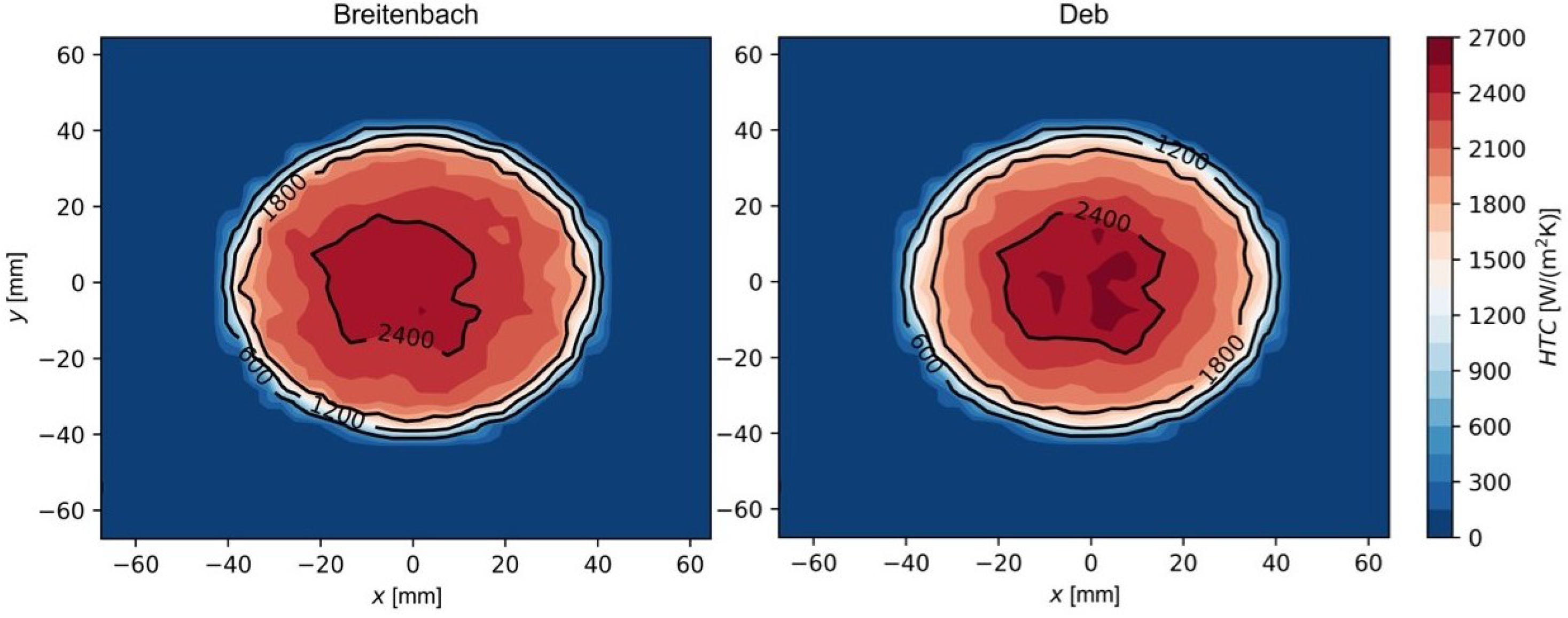
Figure 15 compares the distributions of the heat transfer coefficient on the surface for V s = 15 kg/( m 2 s) and Δ T = 700 K, as obtained from the two models. The resulting profiles are very similar, indicating that both models captured the same overall behaviour. Both models produced nearly concentric contours, with values decreasing radially outward. This trend reflects the reduction in droplet flux per unit area, which scales with the square of the radial distance, as one moves toward the periphery.
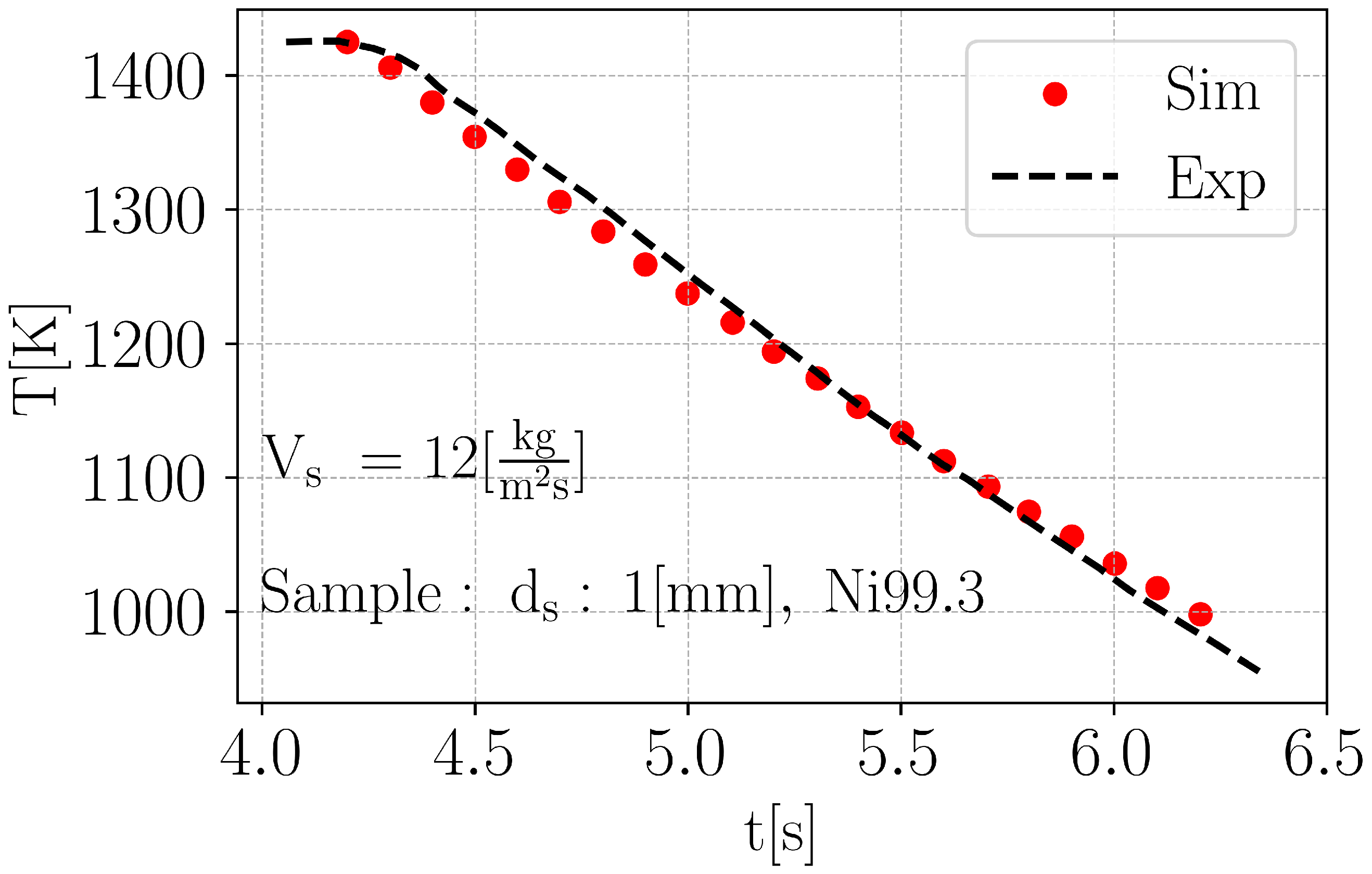
To assess the validity of the CHT implementation, Figure 16 presents the cooling rate measured 1 mm below the surface along the nozzle axis for the case with a mass flux of 12 kg/( m 2 s), using the Breitenbach model. The agreement between the simulated and experimental curves is good, demonstrating that the CHT impingement model can accurately predict the transient cooling behaviour of a workpiece.

4. Conclusions

Spray cooling is employed across various industrial applications, and the possibility of having numerical methods to simulate such applications is valuable for their optimisation. This work therefore focused on the development of a simulation methodology for estimating the heat transfer of sprays above the Leidenfrost temperature. In particular, a CHT model for the heat transfer of an impinging spray above the Leidenfrost temperature is presented and was validated under various operating conditions. For this purpose, a dynamic interaction model [20], along with two models for quantifying the heat exchanged by the droplets (Breitenbach [19] and Deb [14]), were implemented. A coupled boundary condition for the solid–multiphase interface was developed to account for heat exchange between the solid and both the droplets and the surrounding air. For validation, simulations with impinging water were conducted to evaluate model flexibility across varying spray mass fluxes and surface temperatures, and to compare the performance of the implemented droplet heat exchange models.
The experimental correlation used to validate the model was obtained from the work of Wendelstorf et al. [21]. The thermodynamic analysis confirmed that droplet impingement constitutes the dominant heat transfer mechanism, with evaporation occurring predominantly in the near-wall region. Energy conservation at the solid–fluid interface was verified through the consistency between the Eulerian and Lagrangian mass transfer rates. The validation against the experimental correlation of Wendelstorf et al. [21] demonstrated satisfactory agreement across most operating conditions. For the temperature sweep analysis, mean relative errors of 2.32% and 1.78% were obtained for the Deb and Breitenbach models, respectively. For the mass flow rate analysis, mean relative errors of 4.76% and 8.61% were recorded for the Deb and Breitenbach models, respectively. The heat transfer coefficient increased sub-linearly with mass flux, and both the Deb and Breitenbach models correctly captured sensitivity to wall temperature, including the enhancement observed in the transition regime. The Breitenbach model exhibited superior performance in the fully developed film boiling regime, while the Deb model provided better predictions in the transitional region. The transient cooling behaviour of the solid was also accurately reproduced, confirming the reliability of the CHT implementation. Future work will focus on extending the present framework to a broader range of working fluids and nozzle geometries, broadening the applicability of the proposed coupling methodology across diverse spray cooling configurations. In particular, establishing a more rigorous and physically grounded definition of the fitting coefficient X as a function of nozzle geometry and fluid properties represents a direction by which to enhance the overall predictive capability of the modelling framework. Furthermore, incorporating the effects of near-frictionless surface sliding driven by the tangential component of the impact velocity, as studied by Wang et al. [30], could refine heat transfer map predictions in realistic spray configurations, where non-negligible tangential velocity components are encountered.

Author Contributions

M.P.: Conceptualisation, Formal Analysis, Investigation, Methodology, Software, Validation, Visualisation, Writing—Original Draft, Writing—Review And Editing; G.D.: Conceptualisation, Methodology, Supervision; T.L.: Conceptualisation, Methodology, Supervision; P.A.: Conceptualisation, Methodology, Supervision. All authors have read and agreed to the published version of the manuscript.

Funding

This research received no external funding.

Institutional Review Board Statement

Not applicable.

Informed Consent Statement

Not applicable.

Data Availability Statement

The data presented in this study are available on request from the corresponding author.

Conflicts of Interest

The authors declare no conflicts of interest.

Abbreviations

The following abbreviations are used in this manuscript:
Symbols
TTemperature
q Wall heat flux
kThermal conductivity
nNormal coordinate to the surface
Δ h Latent heat of vaporization
UVelocity
V s Spray mass flux
QHeat
A w e t Fraction of wetted surface
ϵ Heat transfer effectiveness
DDiameter
eThermal effusivity
Dimensionless parameters
W e Weber number
L a Laplace number
KInertia parameter
T * Temperature parameter
λ Cumulative wetted area
η w e t Effective wetted ratio
Subscripts
aAir
sSolid
vVapour
lLiquid
wWall surface
s a t Saturation condition
dDroplet
nNormal
Abbreviations
CHTConjugate Heat Transfer
WHFWall Heat Flux
HTCheat transfer coefficient

References

  1. Kita, Y.; Nakamatsu, M.; Hidaka, S.; Kohno, M.; Takata, Y. Quenching mechanism of spray cooling and the effect of system pressure. Int. J. Heat Mass Transf. 2022, 190, 122795. [Google Scholar] [CrossRef]
  2. Yildiz, Y.; Nalbant, M. A review of cryogenic cooling in machining processes. Int. J. Mach. Tools Manuf. 2008, 48, 947–964. [Google Scholar] [CrossRef]
  3. Albertelli, P.; Strano, M.; Monno, M. Simulation of the effects of cryogenic liquid nitrogen jets in Ti6Al4V milling. J. Manuf. Process. 2023, 85, 323–344. [Google Scholar] [CrossRef]
  4. Pusavec, F.; Lu, T.; Courbon, C.; Rech, J.; Aljancic, U.; Kopac, J.; Jawahir, I. Analysis of the influence of nitrogen phase and surface heat transfer coefficient on cryogenic machining performance. J. Mater. Process. Technol. 2016, 233, 19–28. [Google Scholar] [CrossRef]
  5. Su, Y.; Zhang, Y.; Jia, M.; Li, X. Experimental study of the spray-wall interaction under wall boiling conditions at both macroscopic and microscopic scales. Fuel 2026, 413, 138252. [Google Scholar] [CrossRef]
  6. Khan, D.; Hansen, S.; Bjernemose, J.H.; Bebe, J.E.; Lund, I. Experimentation and numerical modeling of SCR spray droplets pre and post impingement on a mixer plate. Fuel 2023, 336, 126788. [Google Scholar] [CrossRef]
  7. Schiller, S.; Brandl, M.; Hoppenstedt, B.; Rudder, K. Wire Mesh Mixer Optimization for DEF Deposit Prevention. In SAE 2015 World Congress & Exhibition, Detroit; SAE Technical Papers; SAE International: Warrendale, PA, USA, 2015; Volume 2015. [Google Scholar] [CrossRef]
  8. Schweigert, D.; Damson, B.; Lüders, H.; Börnhorst, M.; Deutschmann, O. Heat transfer during spray/wall interaction with urea water solution: An experimental parameter study. Int. J. Heat Fluid Flow 2019, 78, 108432. [Google Scholar] [CrossRef]
  9. Bai, C.; Gosman, A.D. Development of methodology for spray impingement simulation. In International Congress & Exposition; SAE International: Warrendale, PA, USA, 1995; SAE Technical Papers; pp. 550–568. [Google Scholar] [CrossRef]
  10. Leidenfrost, J.G. On the fixation of water in diverse fire. Int. J. Heat Mass Transf. 1966, 9, 1153–1166. [Google Scholar] [CrossRef]
  11. Lienhard, J.H., IV; Lienhard, J.H., V. A Heat Transfer Textbook, 5th ed.; Phlogiston Press: Cambridge, MA, USA, 2020; Version 5.10. [Google Scholar]
  12. Karl, A.; Frohn, A. Experimental investigation of interaction processes between droplets and hot walls. Phys. Fluids 2000, 12, 785–796. [Google Scholar] [CrossRef]
  13. Dunand, P.; Castanet, G.; Gradeck, M.; Lemoine, F.; Maillet, D. Heat transfer of droplets impinging onto a wall above the Leidenfrost temperature. Comptes Rendus. Mécanique 2013, 341, 75–87. [Google Scholar] [CrossRef]
  14. Deb, S.; Yao, S.C. Analysis on film boiling heat transfer of impacting sprays. Int. J. Heat Mass Transf. 1989, 32, 2099–2112. [Google Scholar] [CrossRef]
  15. Migliaccio, M.; Montanaro, A.; Paredi, D.; Lucchini, T.; Allocca, L.; D’Errico, G. CFD Modeling and Validation of the ECN Spray G Experiment Under a Wide Range of Operating Conditions; SAE Technical Papers; SAE International: Warrendale, PA, USA, 2019. [Google Scholar] [CrossRef]
  16. Fan, F.; Chen, Z.; Lai, Y.; Liu, J.; Mao, Y. Numerical Simulation and Optimization of Spray Cooling on High-Temperature Surfaces in Industrial Rotary Coolers. Technologies 2025, 13, 589. [Google Scholar] [CrossRef]
  17. Zeraatkardevin, A.; Jowkar, S.; Morad, M.R.; Shen, X. A three dimensional simulation of spray cooling and its evaporating liquid film generated on patterned surfaces. Int. J. Multiph. Flow 2022, 155, 104174. [Google Scholar] [CrossRef]
  18. Zhang, R.; Li, Z.; Kang, J.; Chen, D.; Yuan, G.; Duan, F. Simulation on the spray cooling of a high-temperature cylindrical surface. Int. J. Heat Mass Transf. 2024, 224, 125334. [Google Scholar] [CrossRef]
  19. Breitenbach, J.; Roisman, I.V.; Tropea, C. Heat transfer in the film boiling regime: Single drop impact and spray cooling. Int. J. Heat Mass Transf. 2017, 110, 34–42. [Google Scholar] [CrossRef]
  20. Kuhnke, D. Spray/Wall-Interaction Modelling by Dimensionless Data Analysis; Shaker: Aachen, Germany, 2004. [Google Scholar]
  21. Wendelstorf, J.; Spitzer, K.H.; Wendelstorf, R. Spray water cooling heat transfer at high temperatures and liquid mass fluxes. Int. J. Heat Mass Transf. 2008, 51, 4902–4910. [Google Scholar] [CrossRef]
  22. He, L.; Oldfield, M.L. Unsteady conjugate heat transfer modeling. J. Turbomach. 2011, 133, 031022. [Google Scholar] [CrossRef]
  23. Nordin, P. Complex Chemistry Modeling of Diesel Spray Combustion. Ph.D. Thesis, Chalmers University of Technology, Gothenburg, Sweden, 2001; pp. 1–55. [Google Scholar]
  24. Nappi, A.; Montenegro, G.; Onorati, A.; Della Torre, A.; Dimopoulos Eggenschwiler, P. Modeling the Kinetic and Thermal Interaction of UWS Droplets Impinging on a Flat Plate at Different Exhaust Gas Conditions. In 15th International Conference on Engines & Vehicles; SAE Technical Papers; SAE International: Warrendale, PA, USA, 2021. [Google Scholar] [CrossRef]
  25. Birkhold, F.; Meingast, U.; Wassermann, P.; Deutschmann, O. Analysis of the Injection of Urea-Water-Solution for Automotive SCR DeNOx-Systems: Modeling of Two-Phase Flow and Spray/Wall-Interaction. Analysis 2006, 1. [Google Scholar] [CrossRef]
  26. Rein, M. Drop-Surface Interactions; Springer: Vienna, Austria, 2002. [Google Scholar]
  27. Mundo, C.; Sommerfeld, M.; Tropea, C. Droplet-wall collisions: Experimental studies of the deformation and breakup process. Int. J. Multiph. Flow 1995, 21, 151–173. [Google Scholar] [CrossRef]
  28. Ghavami Nasr, G.; Sharief, R.; James, D.; Jeong, J.; Widger, I.; Yule, A. Studies of High Pressure Water Sprays from Full-Cone Atomizers. In Proceedings of the ILASS-Europe’99, Toulouse, France, 5–7 July 1999. [Google Scholar]
  29. Yoon, S.S.; Hewson, J.C.; DesJardin, P.E.; Glaze, D.J.; Black, A.R.; Skaggs, R.R. Numerical modeling and experimental measurements of a high speed solid-cone water spray for use in fire suppression applications. Int. J. Multiph. Flow 2004, 30, 1369–1388. [Google Scholar] [CrossRef]
  30. Wang, Y.; El Bouhali, A.; Lyu, S.; Yu, L.; Hao, Y.; Zuo, Z.; Liu, S.; Sun, C. Leidnfrost drop impact on inclined superheated substrates. Phys. Fluids 2020, 32, 112113. [Google Scholar] [CrossRef]
Figure 1. Flow diagram of spray impingement model. Red arrows represent the connections among different domains, and light-blue boxes represent the outputs of the Lagrangian sub-models.
Fluids 11 00136 g001
Figure 2. Comparison of rebound and thermal break-up regimes. The dashed box indicates the region below the dimensionless critical temperature, which lies outside the scope of this work.
Fluids 11 00136 g002
Figure 3. Heat fluxes representation in the impinging droplet system: θ is the system coordinate, θ = 0 is the solid interface, while θ = h is the liquid–vapour interface. Rendered from [19].
Fluids 11 00136 g003
Figure 4. Graphical illustration of multiphase–solid thermal coupling boundary condition.
Fluids 11 00136 g004
Figure 5. Sensitivity analysis of solid mesh resolution in direction orthogonal to the impinging surface.
Fluids 11 00136 g005
Figure 6. Sensitivity analysis of fluid mesh resolution in direction orthogonal to the impinging surface.
Fluids 11 00136 g006
Figure 7. Temporal evolution of wall surface condition during the impingement process.
Fluids 11 00136 g007
Figure 8. Graphical rendering of the droplet evolution during the impingement process (half-domain shown; symmetry exploited).
Fluids 11 00136 g008
Figure 9. Graphical rendering of the droplets’ velocity magnitude (colour) and direction (arrows) evolution during the impingement process (half-domain shown; symmetry exploited).
Fluids 11 00136 g009
Figure 10. Wall heat flux state in the impingement interface.
Fluids 11 00136 g010
Figure 11. Graphical rendering of the spray evaporation, represented by the water mass fraction in the Eulerian volume.
Fluids 11 00136 g011
Figure 12. Temporal evolution of the water phase change, computed both from Eulerian and Lagrangian domains.
Fluids 11 00136 g012
Figure 13. HTCs for different mass fluxes: numerical prediction vs experimental correlation. Shaded regions denote the 95% confidence interval of the experimental correlation.
Fluids 11 00136 g013
Figure 14. HTCs for different wall temperatures: numerical prediction vs experimental correlation. Shaded regions denote the 95% confidence interval of the experimental correlation.
Fluids 11 00136 g014
Figure 15. Simulated distribution of heat transfer coefficient for Deb and Breitenbach model for V s = 15 kg/( m 2 s) and Δ T = 700 K.
Fluids 11 00136 g015
Figure 16. Numerical prediction and experimentally derived cooling curve 1 mm below the surface for a plate made of Ni 99.3.
Fluids 11 00136 g016
Table 1. Cases simulated for validation with Wendelstorf equation, spray set up and operating conditions.
Validation Cases
Investigation V s [ kg / m 2 s ] Δ T [K]
V s variation10, 15, 22.5, 30700
Δ T variation15500, 600, 700, 1000
Operating Parameters
U d 14 m/s
D d ≈300–400 μ m
Stand-off70 mm
Cone angle60 deg
T l 298 K
Plate materialNi 99.3
Table 2. Validation quantitative error metrics for the Deb and Breitenbach (Breit.) models.
ValidationStatistics
Metric V s variation Δ T variation
DebBreit.DebBreit.
Mean Absolute Error ( W m 2 K )130.7201.748.2937.14
Mean Relative Error (%)4.768.622.321.78
Peak Error ( W m 2 K )376.8422.486.262.05
Disclaimer/Publisher’s Note: The statements, opinions and data contained in all publications are solely those of the individual author(s) and contributor(s) and not of MDPI and/or the editor(s). MDPI and/or the editor(s) disclaim responsibility for any injury to people or property resulting from any ideas, methods, instructions or products referred to in the content.