


Abstract
Spoof surface plasmon polaritons (SSPPs) offer a powerful way to confine and guide light at terahertz and gigahertz frequencies, but their functionality is typically locked by their static geometries. This study demonstrates the active tuning of SSPP resonances using nematic liquid crystals (LCs) integrated into metallic grating structures. Through full-wave numerical simulations, we show that both reorienting the LC director and inducing the nematic–isotropic phase transition enable the efficient modulation of the SSPP resonance frequency. In the terahertz regime, tuning ranges exceeding 150 GHz are achieved while preserving strong resonant absorption. For GHz-scale structures, we identify optimal configurations—such as partially dielectric-filled grooves topped with an LC layer—that overcome field confinement challenges and provide practical frequency shifts of several gigahertz. These results establish LCs as an effective tuning medium for reconfigurable SSPP devices for future applications in emerging THz and GHz photonics.
1. Introduction
In recent decades, plasmonics has become a major field in photonics, focusing on the interaction between light and collective electron excitations in metals [1,2]. These excitations—surface plasmons—were first predicted in 1957 [3], and research in this area now spans a wide range of resonant phenomena, including surface plasmon polaritons (SPPs) [4], localized surface plasmon resonances [5], gap surface plasmons [6], surface plasmon resonances in core-shell nanoparticles [7], surface lattice resonances [8], and Tamm plasmon polaritons [9,10]. The ability of these excitations to confine light to subwavelength scales [11] and enhance local electromagnetic fields [12] has led to their wide use in various applications, including chemical and biological sensing [13,14,15,16,17,18], surface-enhanced spectroscopy [19], electromagnetic cloaking [20], subwavelength waveguides [21], metamaterials [22], photodetectors (improved efficiency) [23], and lasers [24].
Parallel to developments in nano-optics, there has been growing interest in the terahertz (THz) and gigahertz (GHz) frequency bands [25]. These spectral regions are relevant for applications in security screening [26], medical imaging [27], and wireless communications. The latter encompasses the development of the new 6G wireless communications standard, for which operation in the GHz and THz ranges is being actively explored [28,29]. Conventional plasmonic effects, including SPP resonance, which thrive at optical frequencies, would be prime candidates for manipulating light at these frequencies. However, metals in the THz and GHz regimes behave as near-perfect electrical conductors (PECs) [30], which suppress the field penetration and coupling required to sustain conventional SPP modes [31]. Additionally, in the THz and GHz regimes, the large magnitude of the metal permittivity causes the surface plasmon dispersion to approach the light line, resulting in weakly confined surface waves that increasingly resemble free-space radiation. Consequently, conventional SPPs lose key plasmonic characteristics, such as subwavelength confinement and strong field enhancement, in the THz and GHz regimes.
This limitation has been successfully circumvented by the development of spoof surface plasmon polaritons (SSPPs) [32,33]. Unlike conventional SPPs that propagate on a flat metal–dielectric interface, SSPPs are excited on an interface between a dielectric and a metallic surface with periodic subwavelength corrugations. This structured surface acts as a metamaterial, the electromagnetic response of which is dominated by its geometry [34,35]. The latter allows for the engineering of a geometry that achieves a near-perfect coupling efficiency to SSPPs [36].
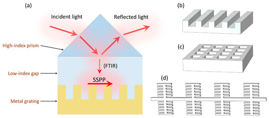
The excitation of SSPPs, similar to that of conventional SPPs, requires momentum-matching techniques due to their propagation constant exceeding the wavenumber of light in free space. A common method employs a prism-based coupler operating on the principle of frustrated total internal reflection (FTIR) [37]. However, due to the PEC behavior of metals at THz frequencies, the Kretschmann configuration [38] cannot excite SSPPs, as the evanescent field cannot effectively penetrate the metal film to excite SSPPs at the metal–dielectric interface. In contrast, in the Otto configuration [39], a dielectric gap is placed between the prism and the metal surface, allowing the evanescent field to reach the interface and enable coupling (Figure 1a), which makes it the more suitable prism-based approach. Alternatively, more advanced approaches utilize dielectric meta-surfaces to couple SSPPs, as well as transmission lines with gaps to achieve the coupling of SSPPs to the radiation mode [40].
Figure 1.
Excitation of SSPP using the Otto configuration (a). Examples of metal grating shapes: 1D array of rectangular grooves (b), 2D array of rectangular holes (c), symmetric 1D array of compound mother–son slots (d).
The foundational structures for supporting SSPPs are gratings formed by periodic corrugations on a metal surface. Among these, one-dimensional geometries such as periodic groove arrays (Figure 1b) are commonly used in applications due to their straightforward design and effective wave confinement [41]. Such designs can be extended by modulating the groove depth [42] or by introducing slanted or two-step grooves, which provide additional degrees of freedom for manipulating the dispersion relation. In two dimensions, arrays of holes or pillars (Figure 1c) and other designs [43] enable polarization control and light manipulation schemes not achievable with one-dimensional designs. A separate class of flat one-dimensional structures should also be noted—the single- or double-sided corrugated transmission lines [44], including profiles with mother–son designs [45]. The latter configuration (Figure 1d) features a larger ‘mother’ groove housing a finer ‘son’ grating, and is particularly valuable for reaching ultra-strong field confinement [46] while retaining the advantages of a single-layer fabrication process.
A fundamental distinction of SSPPs, compared to conventional SPPs, is that their properties are dictated by engineered structural geometry rather than a material’s intrinsic Drude response, enabling superior control over wavevector, confinement, and propagation loss [47]. This engineered low loss, combined with strong subwavelength confinement, makes them exceptionally suitable for integrated photonic circuits, broadband sensing platforms [48,49], near-perfect absorbers [50], reconfigurable filters [51], and compact waveguiding applications [52,53].
Like most plasmonic systems, the operational characteristics of an SSPP structure are intrinsically locked to its precise geometrical parameters post-fabrication, making the ability to design structures with predetermined or tunable properties a critical aspect of the field. For applications that require active, post-fabrication control—such as reconfigurable filters, switches, and modulators—the development of tunable SSPP structures is essential. Current tuning strategies of SSPPs, and THz/GHz metamaterials in general, primarily rely on introducing dynamic physical changes to the system. These include the use of a movable dielectric disturber to perturb the electromagnetic field locally, mechanical actuation to alter critical dimensions, a metal–insulator transition in VO2 thin films [52,54], and modifying the Fermi energy in a graphene sheet near the SSPP grating through chemical doping [55,56,57]. The search for efficient, wide-range, and fast tuning mechanisms continues to be a key research focus.
Liquid crystals (LCs), and nematic liquid crystals (NLCs) in particular, represent a highly promising class of tunable materials for this purpose. NLCs are mesophases characterized by the long-range orientational order of their rod-like molecules, described by a macroscopic director field. The orientation of the director can be reconfigured by applying external electric, magnetic, and light fields, while the magnitude of the birefringence can be modulated by temperature [58,59]. This reorientation provides a powerful mechanism for tuning the optical properties of a system [60,61,62]. By integrating an LC cell into an SSPP structure, this effect can be used to dynamically control the device’s electromagnetic response.
LCs have been successfully used to dynamically tune a wide range of photonic systems, from optical to millimeter-wave applications [63,64,65,66]. The demonstrated tuning applications include shifting resonances in metallic nanoantennas [67], modulating propagation in plasmonic waveguides [68,69], controlling resonant frequencies and beam coupling [70,71,72,73], as well as enabling reconfigurable phase shifters [74], tunable antennas [75,76], and micro-gratings [77,78], LC-controlled surface plasmon resonance sensors [77], and adjustable laser cavities [79,80,81], among others. Additionally, under certain conditions, the anisotropy of the LC layer can enable the excitation of new surface electromagnetic modes—Dyakonov waves [82]. The established versatility of LCs in dynamically controlling light–matter interactions highlights their potential for enabling the active tuning of SSPPs. It should be noted that LCs have previously been used to tune several types of SSPP structures [43,83,84,85]. Namely, in Ref. [43], continuous tuning from 0.48 to 0.54 THz was reported for a metastructure with H-shaped metaatoms supporting non-diffractive SSPP propagation. In Ref. [83], LCs were used to tune a phase shifter based on SSPPs with common-mode suppression in the microwave spectral region. SSPP propagation in a gradient dielectric-filled metallic grating was studied in Ref. [84], highlighting that using LCs can be promising for achieving continuous tuning in such structures. In Ref. [85], the dispersion of SSPPs was studied in structures with a corrugated perfect conductor–dielectric interface, highlighting the potential tunability of SSPP dispersion using LCs. Extending these concepts to the control of other SSPP structures with LCs therefore shows significant promise.
In this work, we explore the active tuning of SSPPs in the GHz and THz frequency ranges through the integration of NLCs. In contrast to [43,83,84,85], the present study investigates LC-controlled resonant SSPP modes in corrugated metallic gratings, demonstrating the direct tuning of the SSPP resonance frequency in both the GHz and THz regimes. The dynamic control of SSPP propagation is achieved through two primary mechanisms: reorientation of the LC director and thermal tuning through the nematic-to-isotropic phase transition. This study demonstrates efficient modulation of the SSPP resonance frequency across both the GHz and THz frequency regimes, offering new ways for developing fully reconfigurable plasmonic devices.
2. Structure Description, Materials, and Methods
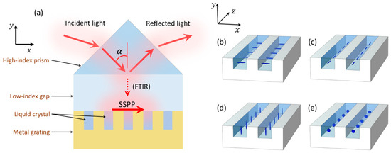
When integrating LCs into photonic and plasmonic resonant structures, they are typically placed in regions of the highest electromagnetic field enhancement to achieve maximum tuning ranges [65,75]. Since the SSPP resonance in a 1D rectangular grating (as in Figure 1a) results in a significant electromagnetic field enhancement in the grooves, we consider an SSPP structure where the grooves are filled with an NLC (Figure 2a). Reorienting the NLC director by applying external fields changes the dielectric tensor in all frequency ranges, including the SSPP frequency. This results in the SSPP ‘perceiving’ a different dielectric permittivity of the grooves, shifting the resonance frequency. Because the SSPP mode is strongly influenced by the dielectric environment of the grooves, reorienting the NLC, which changes the effective permittivity experienced by the mode, affects the electromagnetic energy stored in the grooves (i.e., their effective capacitance) and in turn shifts the resonance. In order to assess the tunability range of the resonance frequency in LC-tuned structures, it is often sufficient to investigate the transitions between the principal orientations of the director, namely the x-planar (, Figure 2b), z-planar (, Figure 2c), homeotropic (, Figure 2d), and isotropic (Figure 2e) configurations.
Figure 2.
Excitation of SSPP in a metal grating with LC-filled grooves (a). Schematic depiction of refractive index ellipsoids in four principal LC configurations: x-planar (b), z-planar (c), homeotropic (d), and isotropic (e).
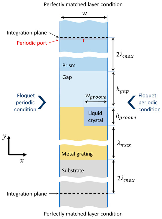
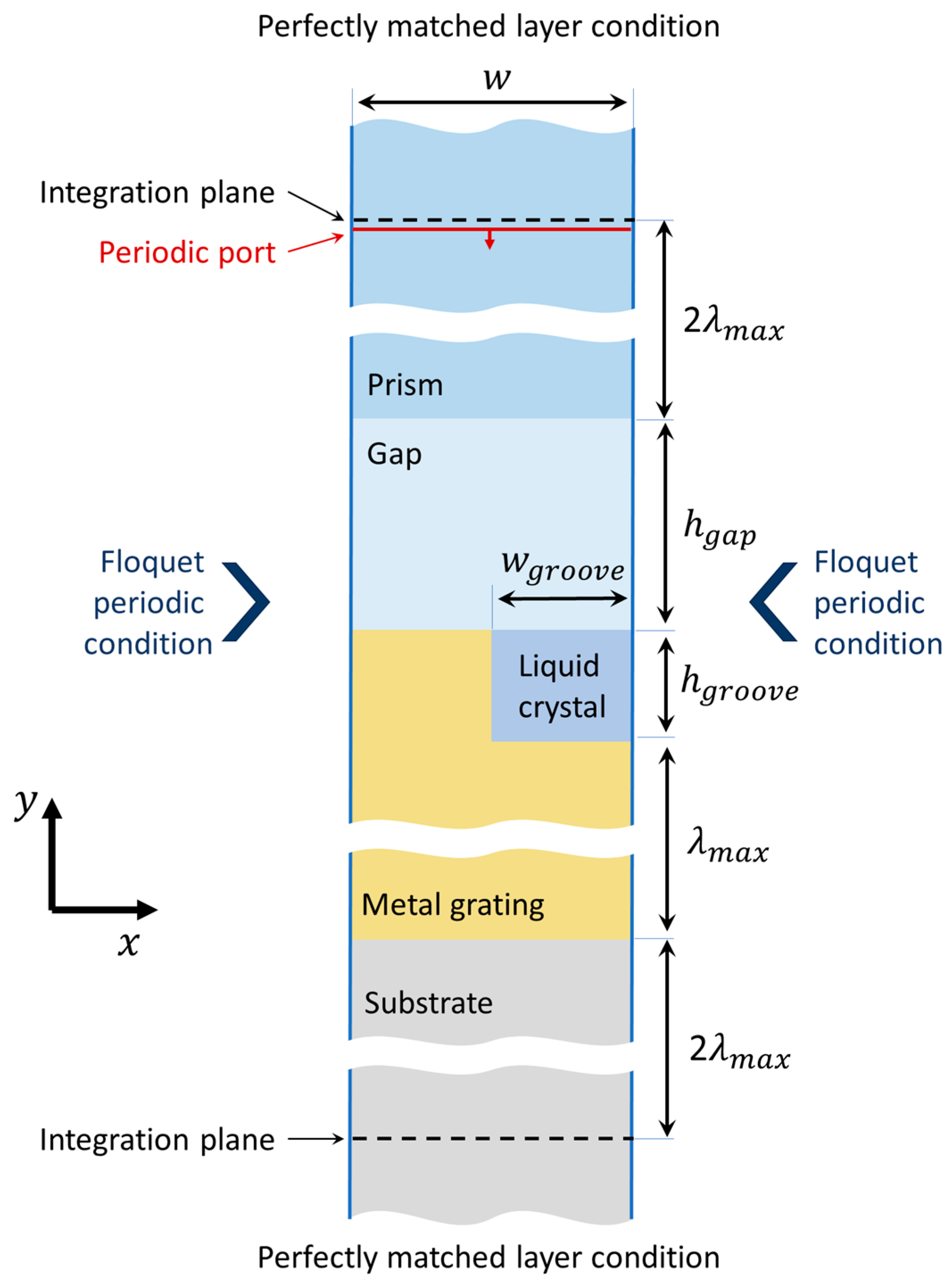
The studied structure (Figure 2a) can be considered uniform in the z direction. The incident electromagnetic wave, polarized linearly in the -plane, propagates in the -plane and forms an angle with the -axis in the prism. Due to the uniformness in the direction of the structure and the initial conditions, the solution for the electromagnetic field will also be uniform in the z direction. Furthermore, if the prism is sufficiently large in the direction, the structure (Figure 2a) can be considered periodic in the direction, with a 2D unit cell in the -plane shown in Figure 3.
Figure 3.
Unit cell of the SSPP structure.
The SSPP excitation in the structure was studied by solving Maxwell’s equations using the finite element method in COMSOL Multiphysics v. 6.2. The reflectance and transmittance spectra were calculated by integrating the normal Poynting component above and below the structure, and the absorbance spectra were calculated by integrating the resistive losses over the volume of the unit cell. The integration planes for reflectance and transmittance integrals were located away from the nearest structural elements, ensuring no near-field contributions, where is the maximum wavelength in the studied spectra. For the transmittance calculation, a dielectric substrate layer was added, so that the integration of the normal Poynting component is performed in a non-lossy medium. It should be noted that in all studied structures the transmittance turned out to be effectively zero due to the near-PEC properties of the metal layer with a thickness of in the THz and GHz frequencies, meaning that the material of the substrate does not influence the SSPP properties if the metal layer is sufficiently thick.
In order to correctly account for the phase shifts of the oblique electromagnetic waves accumulated over the structure’s period, the Floquet periodic conditions were used. The phase shifts were derived from the Floquet vector, which is in turn determined from the periodic port. The semi-infinite spans of the prism in the direction and the substrate in the direction were modelled by using Cartesian perfectly matched layers, which prevent waves propagating away from the structure from getting reflected back into the SSPP structure.
The mesh was adapted to reflect the peculiarities of the structure, such as accounting for a finer resolution at the locations with high near-field enhancement, an increased dielectric permittivity in the prism and NLC, and a rapid wave intensity change in the metal. The mesh was additionally made to be compliant with the symmetry requirements in the perfectly matched layers for correct domain stretching and on the periodic boundaries for correct element mapping. The obtained numeric results were verified to be stable with respect to the mesh adjustments.
The high-index prism had a refractive index [49], and the air gap’s and the substrate’s refractive indexes were equal to 1. The metal grating was made of gold, with the real and imaginary components of the refractive index taken from [86] for the THz frequency range, while the gold’s conductivity was taken from [52] for the calculations in the GHz range. The dimensions of the structure are μm, μm, μm, and μm. The values of the ordinary () and extraordinary () refractive indexes of the NLC and the incidence angle are specified in the following sections separately.
3. Tuning Spoof Plasmons in THz
3.1. Tuning by Reorienting the LC Director
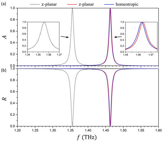
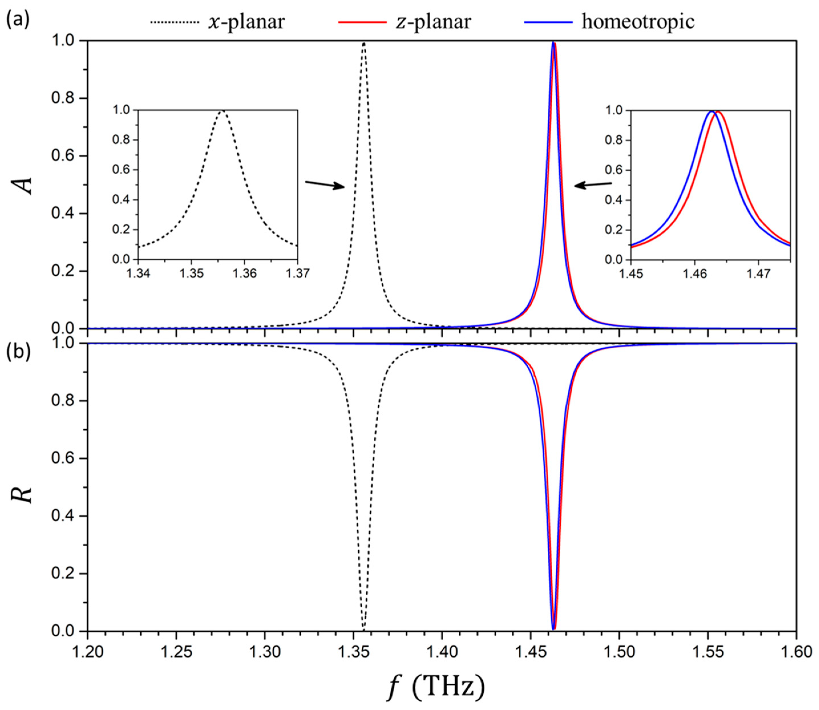
We first consider a typical LC mixture with a moderately high anisotropy of with and —typical values for widely used LCs in THz such as 5CB and E7 [87]. Figure 4 shows the absorbance () and reflectance () spectra of the structure for the x-planar, z-planar, and homeotropic NLC director orientations for the incident wave propagating obliquely at an angle degrees.
Figure 4.
Absorbance (a) and reflectance (b) spectra of the SSPP structure for the x-planar, y-planar, and homeotropic NLC director configurations. The insets show enlarged views of the absorbance peaks.
The reflectance and absorbance spectra show a single dip and peak, respectively, with the full width at half-maximum (FWHM) of approximately 0.01 THz, associated with the excitation of SSPP resonance. The amplitude of the peaks approach unity, highlighting the high effectiveness of the SSPP excitation and indicating that this structure behaves as a perfect metamaterial absorber at the SSPP resonance frequency. At the frequencies far from the SSPP resonance, the total internal reflection cannot be effectively attenuated by the SSPP’s excitation, resulting in the reflectance of the structure approaching unity, and the absorbance nearing zero. Since the transmittance of the structure is effectively zero, the absorbance can be derived from the reflectance using a simple relation . The latter condition was carefully verified for all structures studied in this paper; therefore, only the reflectance spectra are presented in the subsequent figures for conciseness.
Reorienting the NLC director from the x-planar state to the z-planar or homeotropic state shifts the resonance peak in absorbance and dip in reflectance spectra towards larger frequencies by approximately 0.1 THz. The differences in reflectance and absorbance spectra between the z-planar and homeotropic NLC director orientations are minimal; therefore, the SSPP is not sensitive to the NLC director reorientation in the -plane.
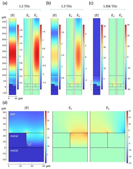
The difference observed in the SSPP’s sensitivity to the NLC director reorientation in different planes can be explained by analyzing the distribution of the electric field components in the structure. Figure 5a–c shows the distribution of the electric field magnitude and the x- and y- electric field components in the unit cell for frequencies far from the SSPP resonance (a), near it (b), and directly at the resonance peak (c) for the -planar director orientation. The electric field is given in the units of the incident wave’s electric field amplitude . It should be noted that the and plots are snapshots of the electric field components at a single point of the oscillation phase, while corresponds to the phase-independent electric field norm. When the frequency of the incident wave is far from the SSPP resonance (Figure 5a), the incident wave undergoes a total internal reflection at the prism–gap interface ( μm). Therefore, the electromagnetic field in the prism can be approximated as an interference of the incident and reflected waves with equal amplitudes and wavevectors of and , respectively:
Figure 5.
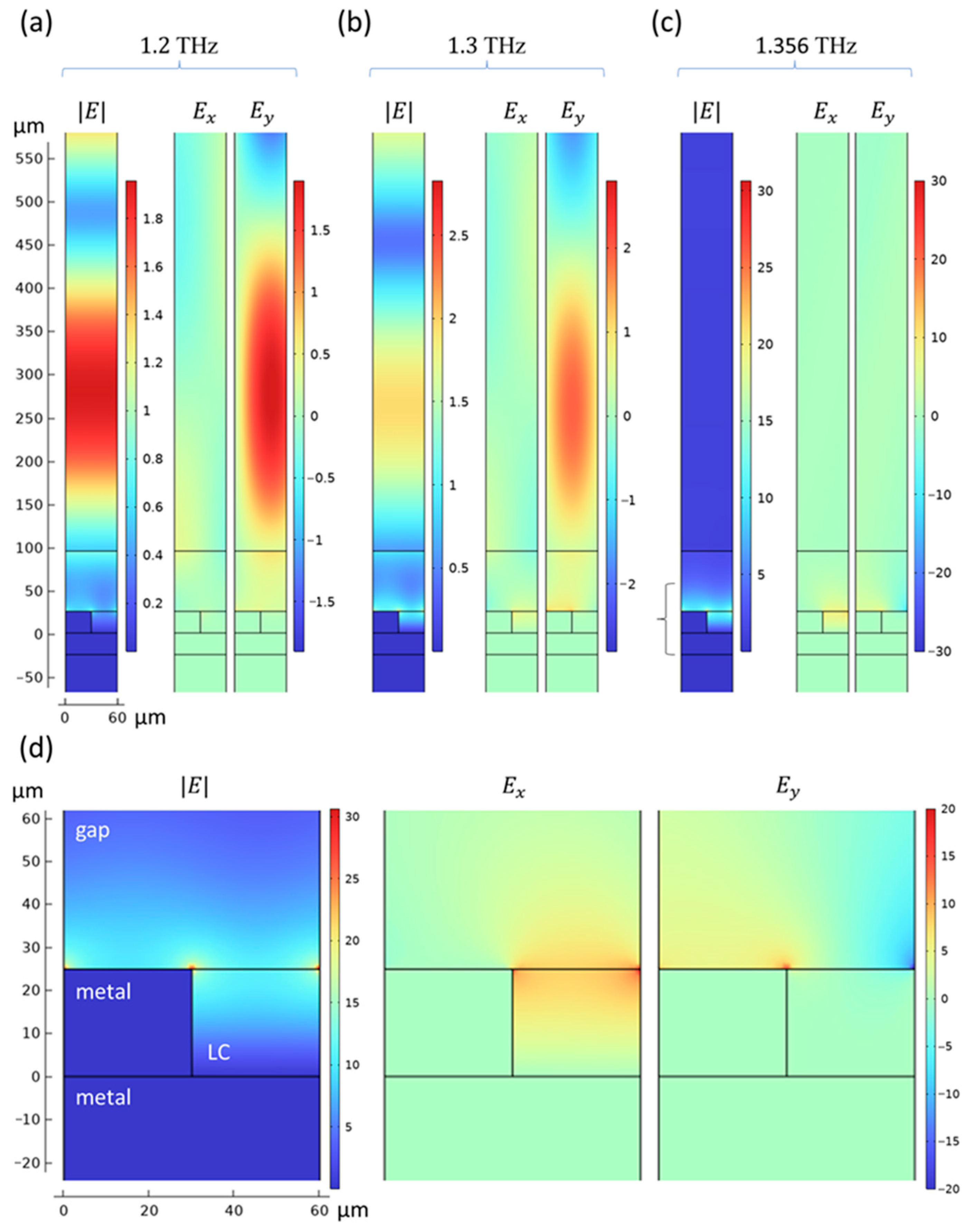
Distribution of the electromagnetic field components in the structure’s unit cell (see Figure 3) at frequencies far from resonance (a), near resonance (b), and at resonance (c). Enlarged view of the area near the SSPP localization at the resonance frequency of 1.356 THz (d). The bracket shown next to (c) indicates the area that is enlarged in (d). Note the different color scale ranges in panels (a–d).
The electric field magnitude in the gap ( μm μm) forms an evanescent wave that decreases the amplitude with decreasing coordinates. A noticeable electric field enhancement is observed near the metal grating (Figure 5a, μm), which suggests emerging SSPP excitation, even at frequencies far from the SSPP resonance (by about 0.15 THz). The and electric field component distributions follow the above-mentioned considerations, showing a propagating wave in the -direction and a mostly standing wave in the -direction. The component is generally stronger than the due to a very oblique incidence angle .
When the frequency gets closer to the SSPP resonance frequency (Figure 5b), the enhancement of the electromagnetic field near the metal grating starts to increase. A significant electric field enhancement now occurs near the angles of the metal grating, while the absorbance is still mostly negligible at THz (Figure 4a, -planar NLC director orientation). As the frequency reaches the SSPP resonance value of approximately THz (Figure 5c), the electric field enhancement near the metal grating increases by more than an order of magnitude. Unlike the cases far from the resonance (Figure 5a), the component of the electric field becomes comparable in magnitude to the component near the resonance frequency (Figure 5c).
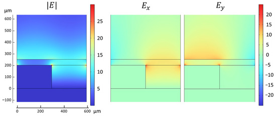
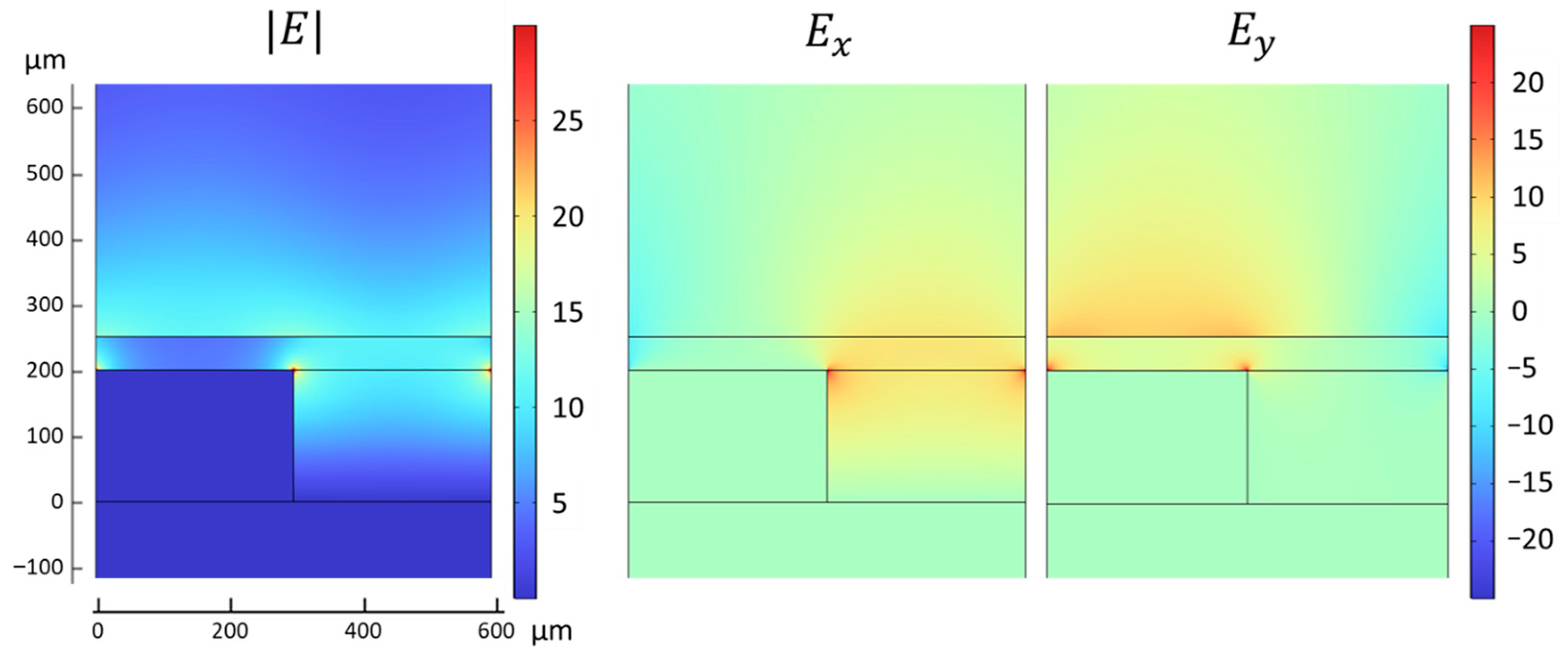
A closer examination of the electric field distribution at the SSPP resonance frequency near the metal grating (Figure 5d) shows that the electric field has its maximum enhancement at the edges of the metal grating, reaching a value approximately 30 times the amplitude of the incident wave’s electric field. Within the NLC layer, the component of the electric field is dominant, while the component is enhanced above the NLC cell. This makes the SSPP resonance sensitive to the -component of the dielectric permittivity tensor , thus explaining the sensitivity of the SSPP resonance frequency to the reorientation in the - and -planes (i.e., and ) and the lack thereof in the -plane (i.e., ) (Figure 4).
The dispersion relation of SSPPs can be approximated by the following equation (see Supplementary Material S1):
where is the free space wavenumber, is the imaginary unit, and the summation is carried out across all diffraction orders . As can be seen from (2), the SSPP dispersion is dependent only on the component of the dielectric permittivity tensor . Therefore, reorienting the LC in such a way that maximizes the change in results in the best tunability range of the SSPP resonance frequency.
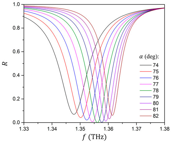
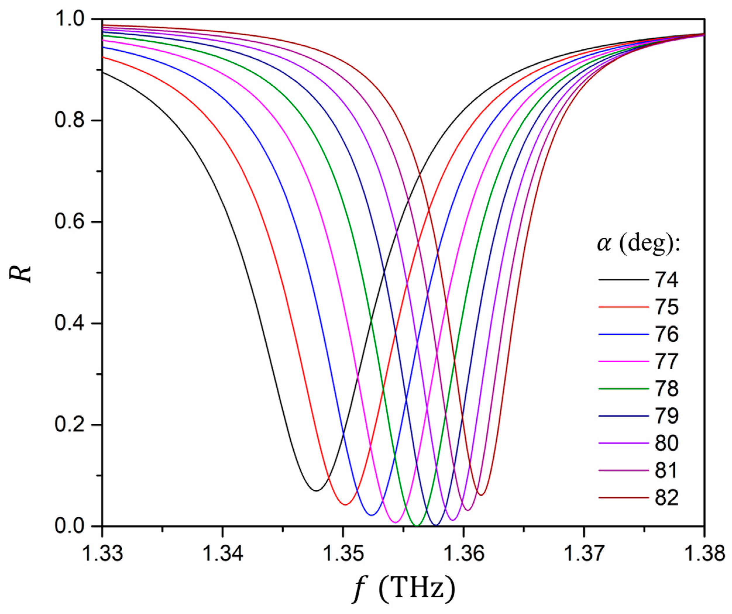
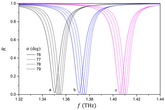
Figure 6 shows the dependence of the reflectance spectrum near the SSPP resonance reflectance dip on the incidence angle in the case of -planar NLC director orientation. Deviation from the optimal incidence angle ( degrees) by 3 degrees increases the minimum reflectance value (i.e., makes the reflectance dip shallower) by approximately 0.04. Overall, an increase in the incidence angle leads to an increase in the frequency of the SSPP resonance and to a decrease in its FWHM.
Figure 6.
Dependence of the 1.35 THz SSPP resonance reflectance dip for the -planar director orientation on the incidence angle .
When using LCs to tune plasmonic metastructures, an increase in the optical (i.e., finite-frequency) anisotropy of the LC typically leads to an increase in the frequency tuning range [75]. Therefore, when assessing the LCs’ potential for tuning the SSPP resonance, it is important to consider the LCs with the largest optical anisotropy values. In the more explored optical frequency range, the largest reported LC optical anisotropy reaches approximately [88,89]. While the optical anisotropies of LCs in the THz and GHz ranges are generally comparable to such in the optical range [90], the highest reported LC optical anisotropy in the THz range to this day is within [63,90,91,92]. Therefore, in order to assess the maximum achievable tuning range, an NLC with , , and was used, corresponding to the 1825 LC mixture from [90].
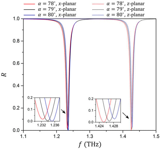
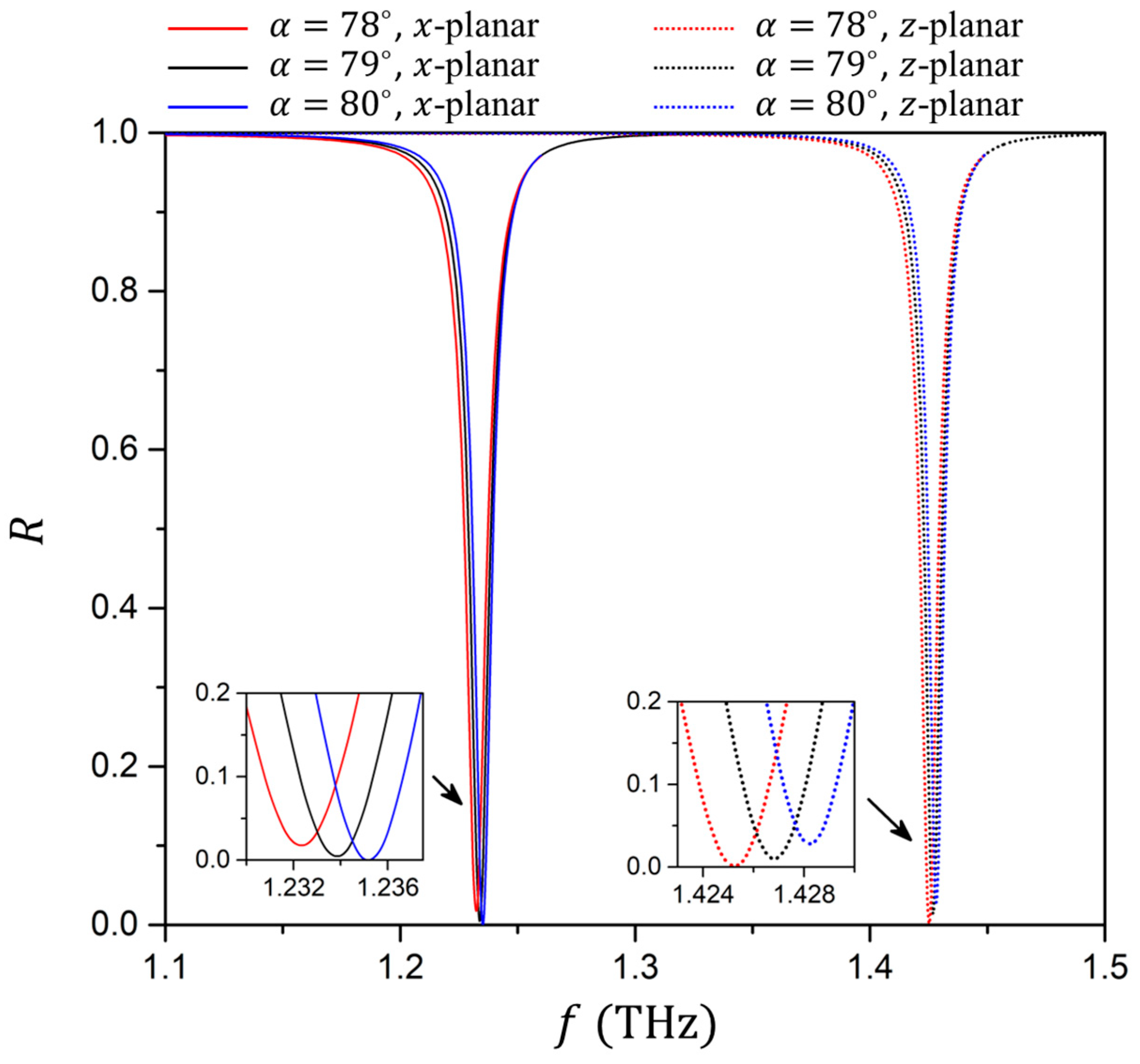
In Figure 7, the reflectance spectra for a high-anisotropy LC are shown. The increased LC anisotropy naturally leads to an increased SSPP resonance frequency tuning range, from 1.23 to 1.42 THz. The insets in Figure 7 show how the SSPP resonance reflectance dip changes with the incidence angle . It can be seen that the reflectance dips corresponding to the -planar and -planar NLC director orientations have different optimal incidence angles : 80 degrees and 78 degrees, respectively. This effect becomes more pronounced with higher NLC anisotropy values. Nevertheless, choosing an intermediate incidence angle of 79 degrees allows the reflectance dips for both NLC director orientations to achieve an amplitude of approximately 0.99.
Figure 7.
Reflectance spectra of the structure with a high-anisotropy NLC for the -planar and -planar director orientations at different incidence angles . The insets show enlarged views of the reflectance dips.
3.2. Tuning by Inducing a Nematic–Isotropic Transition
It should be acknowledged that in the structures studied in the previous section, the conventional way of controlling the LC orientation, i.e., by applying an external electric field, can become challenging due to the LC-filled groove being surrounded by metal from three directions. Alternative strategies for controlling the LC director orientation are also available, including magnetic-field actuation and modifying the boundary conditions through photoalignment [93,94,95], dendrimer coatings [96,97], or surfactants such as CTAB [98,99]. An additional approach for influencing the LC’s dielectric permittivity tensor is the temperature-induced nematic–isotropic phase transition, which is explored below. This effect was modeled using the data reported in Ref. [100], where the refractive indexes and of E7 LC mixture were measured at several temperature points along the nematic–isotropic phase transition.
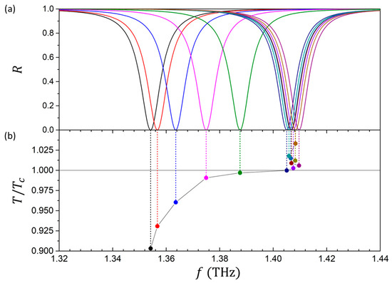
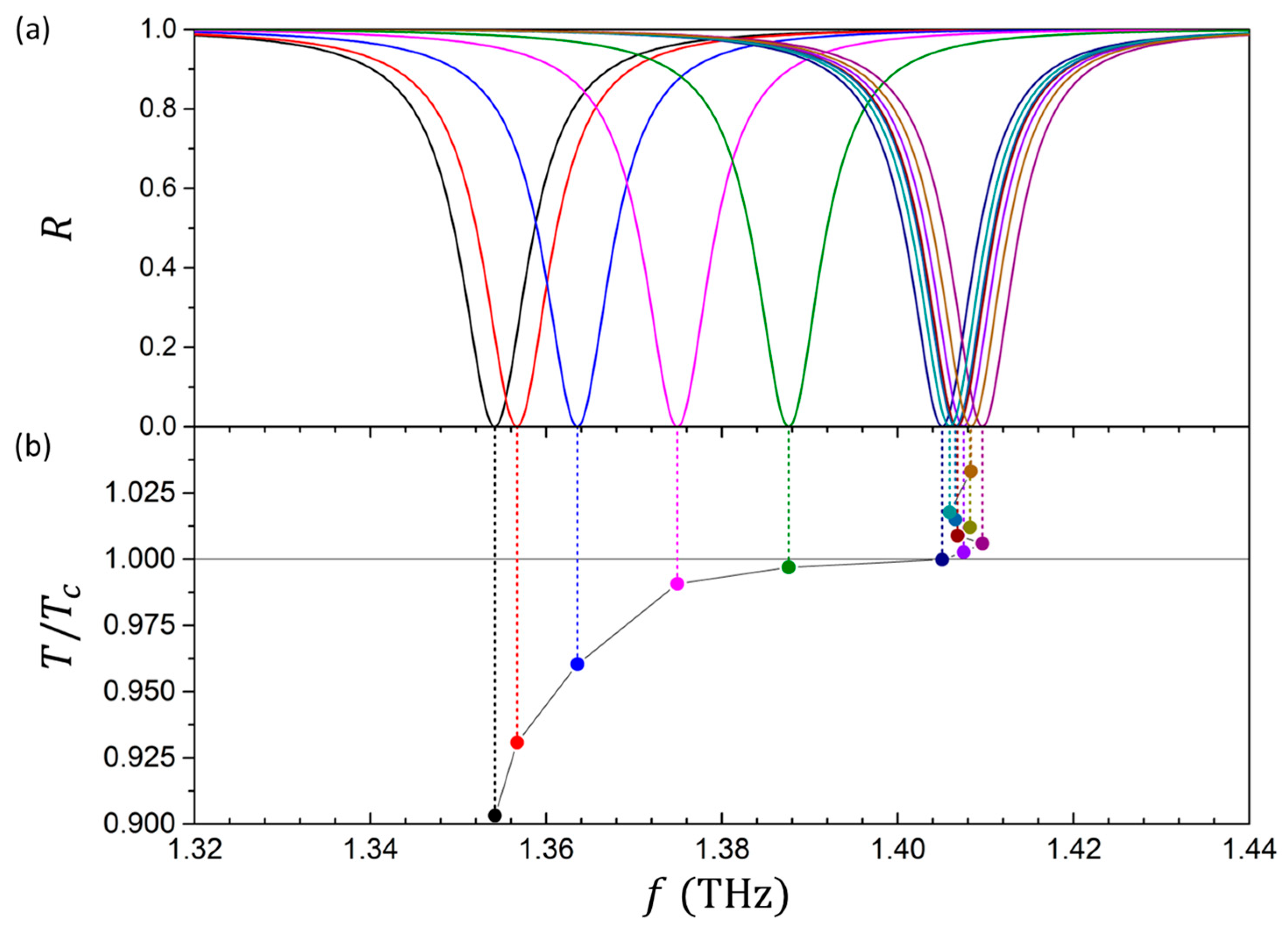
Figure 8a shows the calculated reflectance spectrum over a range of temperatures as the LC transitions from a uniform -planar state to an isotropic state, while Figure 8b maps the centers of the SSPP resonance reflectance dips in Figure 8a to the normalized temperature scale. An increase in temperature below the clearing point (i.e., ) leads to a decrease in the LC’s optical anisotropy, resulting in an increase in the SSPP resonance frequency from approximately 1.354 to 1.405 THz. As the temperature reaches the clearing point , the optical anisotropy of the LC vanishes completely, and further increases in the temperature do not shift the plasmonic reflectance dips except for a small non-monotonic jittering of the dip’s position, dictated by the non-monotonic jittering of the experimental dependence of the isotropic refractive index for in Ref. [100].
Figure 8.
SSPP resonance reflectance dips in the reflectance spectra at different normalized temperatures (a). Mapping of the SSPP resonance reflectance dip frequencies to the normalized temperature (b).
Similar to the case in Figure 4, a moderate LC anisotropy leads to optimal incidence angles at different temperature points as shown in Figure 9, allowing for the selection of a single angle ( degrees) that results in almost-perfect absorbance at all temperatures. Moreover, the mentioned non-monotonic jittering in the SSPP resonance reflectance dip frequency’s dependence on temperature can potentially be smoothened by introducing a distribution of incidence angles .
Figure 9.
Dependence of SSPP resonances on the incidence angle at the temperature points .
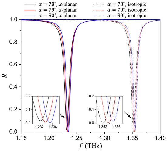
In order to assess the maximum achievable tuning range through the induction of the nematic–isotropic phase transition, we once again consider the high-anisotropy NLC with , , and [90]. Since data on the temperature dependence of such high-anisotropy LCs in the THz frequency range is limited, we consider two principal states: the -planar state described by the refractive indexes and , and the isotropic state described by a single isotropic refractive index . The corresponding reflectance spectra are shown in Figure 10. Naturally, the higher optical anisotropy of the NLC results in a higher SSPP resonance frequency tuning range (from approximately 1.23 to 1.35 THz) compared to the case in Figure 8a (from approximately 1.35 to 1.41 THz).
Figure 10.
Reflectance spectra for the -planar and isotropic NLC states for the NLC with a high optical anisotropy. The main panel corresponds to the incident angle degrees; the insets show the variation in reflectance dips when is varied from 78 to 80 degrees.
4. Tuning Spoof Plasmons in GHz
It is important to consider possible SSPP tuning in the GHz (or, more precisely, sub-THz) range, namely within the frequencies of 100–500 GHz. This frequency range is of particular interest in the context of potential 6G applications. Generally, if the dielectric properties of the structure have a relatively gradual dependence on the frequency, the structure can be directly scaled to switch to a different operating frequency range. Since spoof plasmons operate in a regime where the metal grating can be regarded as a near-perfect electric conductor both in GHz and THz, simply scaling up the structure in size is a promising starting point to enable the studied structure to operate in the GHz frequency range.
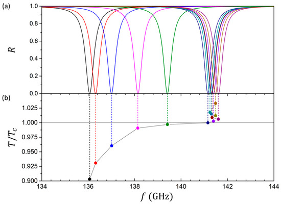
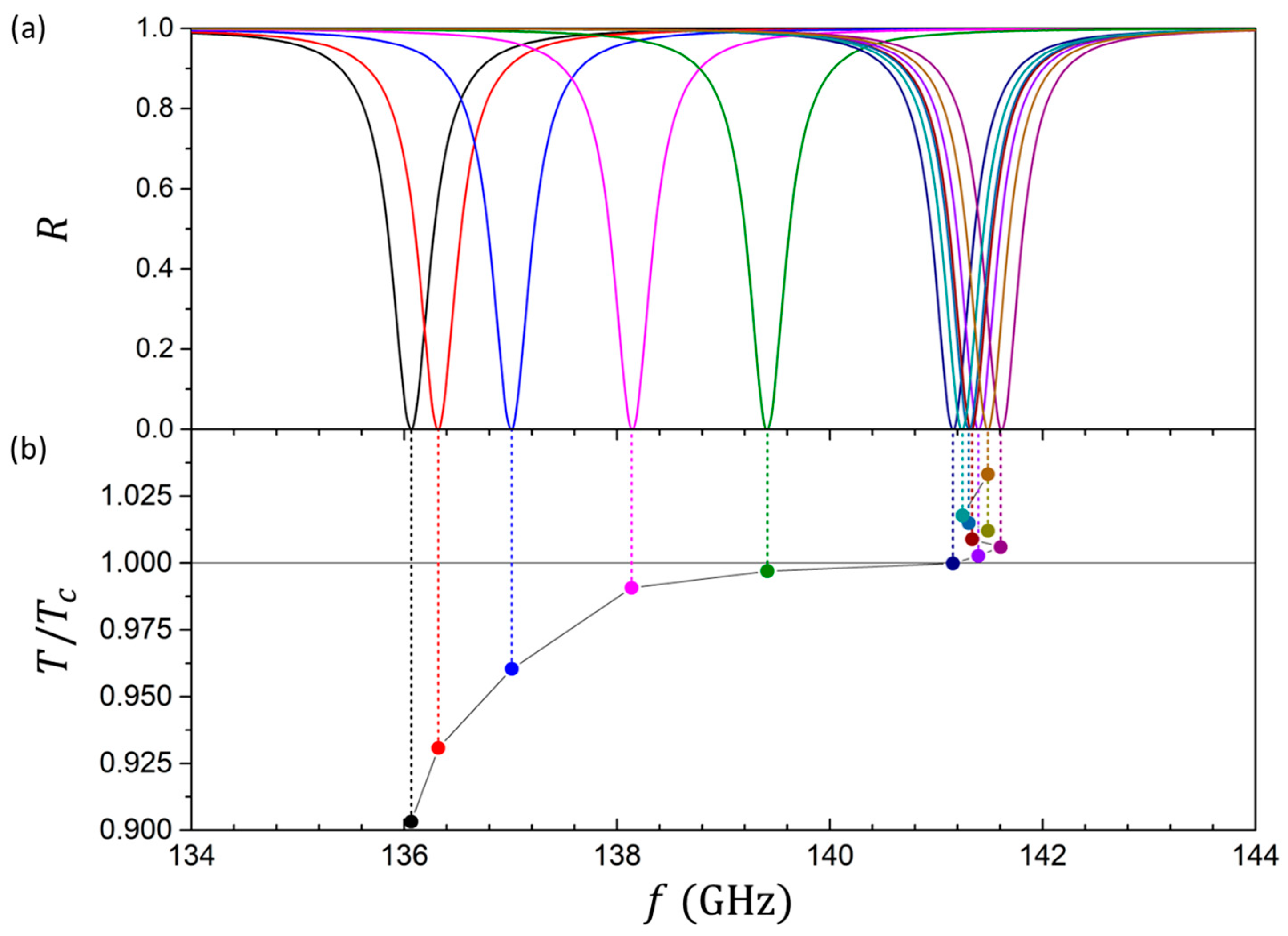
Figure 11 shows the reflectance spectrum for the structure scaled up 10 times: μm, μm, μm, and μm, where the grooves are filled with the E7 LC [100], similar to the case in Figure 8. The optimal incidence angle was adapted to the changes in the dielectric function of the metal grating and was found to be 82 degrees, slightly larger than in the THz case above (Figure 8). The frequency tuning range scales with the operating frequency, allowing the SSPP resonance frequency to be tuned from approximately 136 GHz at to 141.5 GHz at . The distribution of the electric field components and and the electric field magnitude in the structure remain similar to the previously described case in the THz regime (Figure 5).
Figure 11.
SSPP resonance reflectance dips in the reflectance spectra at different normalized temperatures in GHz (a). Mapping of the SSPP resonance reflectance dip frequencies to the normalized temperature (b).
It should be noted that while it is challenging to achieve a uniformly oriented 250 μm thick pure NLC cell, recently a method was introduced to obtain polymer–NLC composite cells with a fast response time and a thickness of up to 1.5 mm [101]. Similar to polymer-dispersed liquid crystals (PDLCs), such composites consist of NLC droplets in the polymer matrix. However, the proposed composites, unlike PDLCs, have a low polymer concentration, similar to polymer-stabilized liquid crystals (PSLCs), resulting in thin polymer borders between large LC droplets. Such composites unify the best properties of PDLCs and PSLCs, largely preserving the dielectric and optical properties of the LCs.
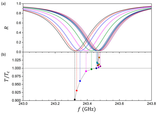
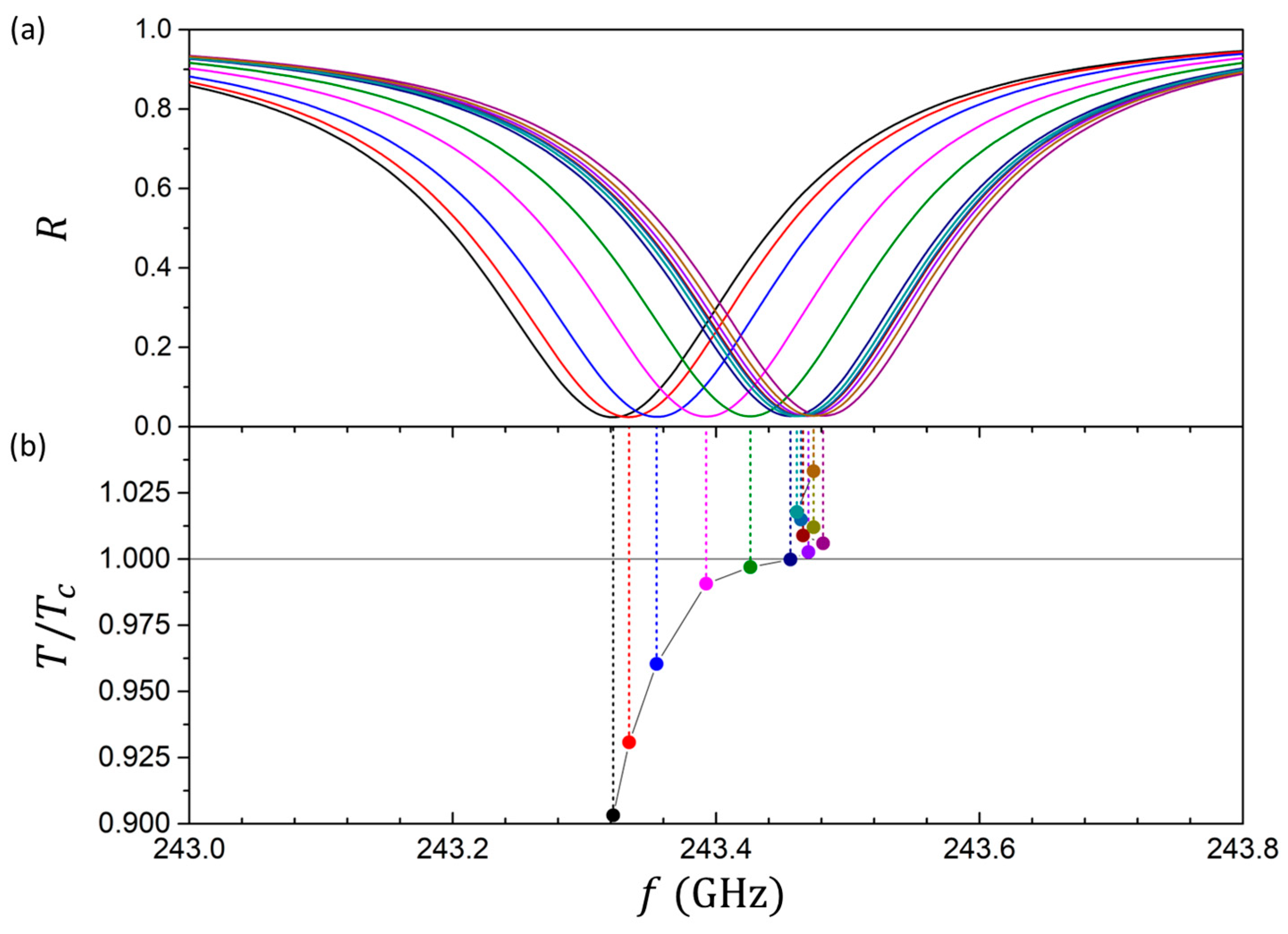
While very thick LC cells, as shown above, can be effective in controlling the SSPP resonance frequencies in GHz, it is also important to investigate whether comparable tunability can be achieved with LC cells of regular thickness. In order to decrease the LC cell thickness toward more commonly used values (several tens of microns), several approaches can be considered, out of which the most straightforward one is to directly decrease the depth of the LC-filled grooves. While decreasing the groove depth, the other parameters (incidence angle , gap height , and prism refractive index ) need to be significantly adjusted to maintain strong coupling. Figure 12 shows the reflectance and absorbance spectra for the SSPP structure with the groove depth decreased to μm. The corresponding incidence angle is degrees, the gap height is μm, and the prism refractive index is .
Figure 12.
SSPP resonance dips in the reflectance spectra at different normalized temperatures for the scaled structure with shallow grooves of μm (a). Mapping of the SSPP resonance reflectance dip frequencies to the normalized temperature (b).
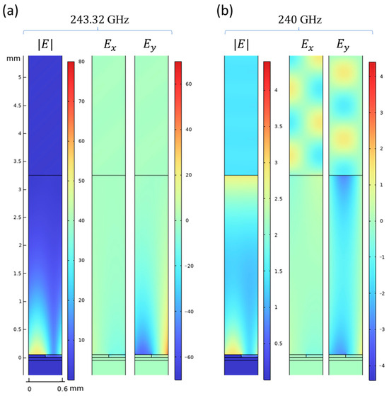
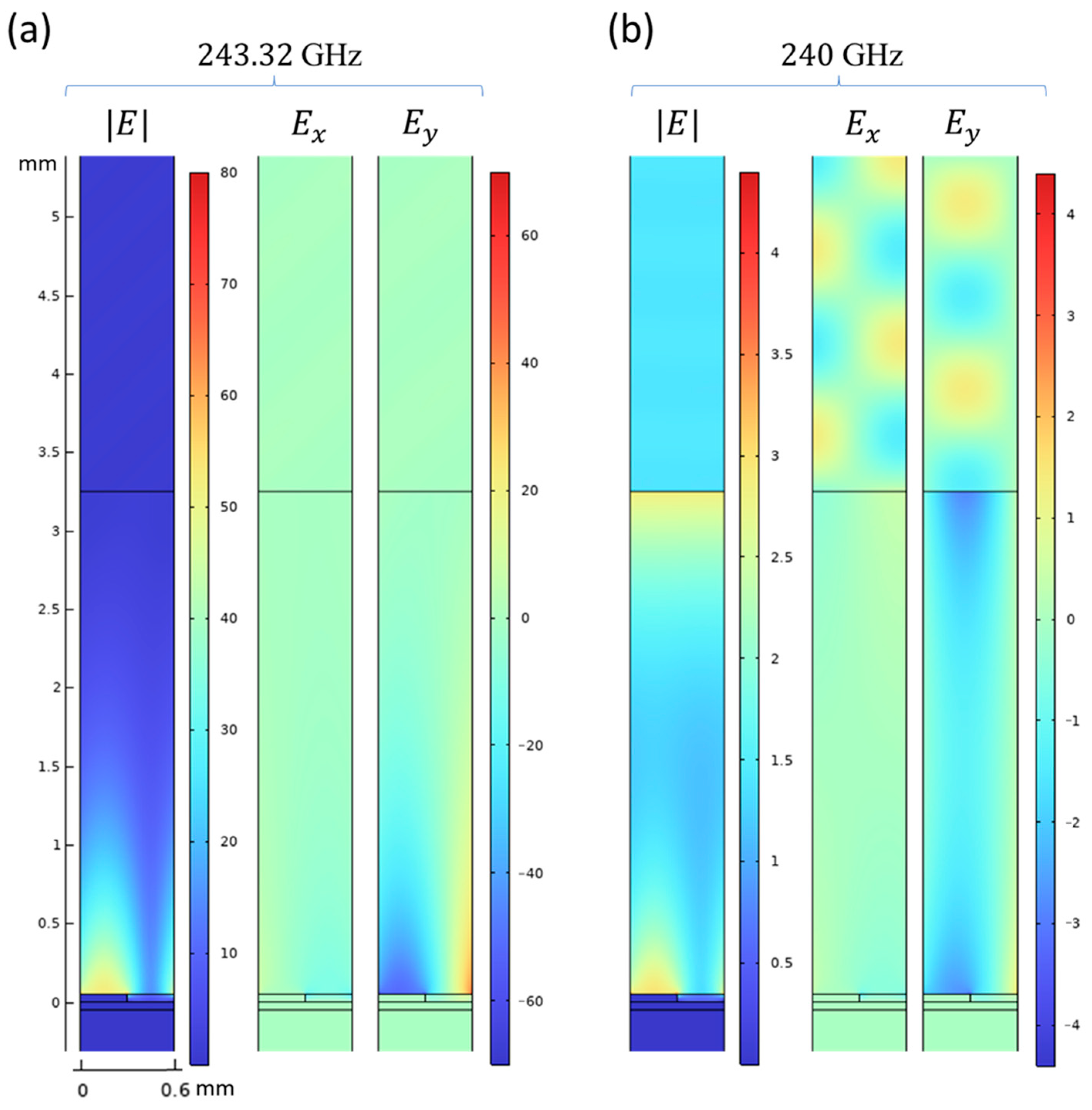
While the temperature change allows for a gradual tuning of the resonance frequency, the frequency control range for such a structure is significantly lower. This happens primarily due to the change in the localization of the SSPP field enhancement (Figure 13a): it extends far into the gap, away from the grooves, and the SSPP thus becomes much less sensitive to the optical properties of the NLC layer. In addition to the mentioned shift, the SSPP becomes much less localized overall, requiring an increased gap height and smaller incidence angles that barely satisfy the total internal reflection condition. It should also be noted that the decreased optimal incidence angle can lead to hybrid mode excitation, as in Figure 13b at 240 GHz. Therefore, the structures with larger groove depths are apparently superior for LC-based resonance frequency tuning; however, reducing the groove depth may still be preferred to match commonly used LC cell thicknesses, resulting in a trade-off between SSPP tunability range and practical cell dimensions.
Figure 13.
Distribution of the electromagnetic field components in the structure with shallow LC-filled grooves at the at the resonance frequency of GHz, corresponding to (a), and far from the resonance (b). Note the different color scale ranges in panels (a,b).
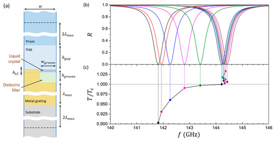
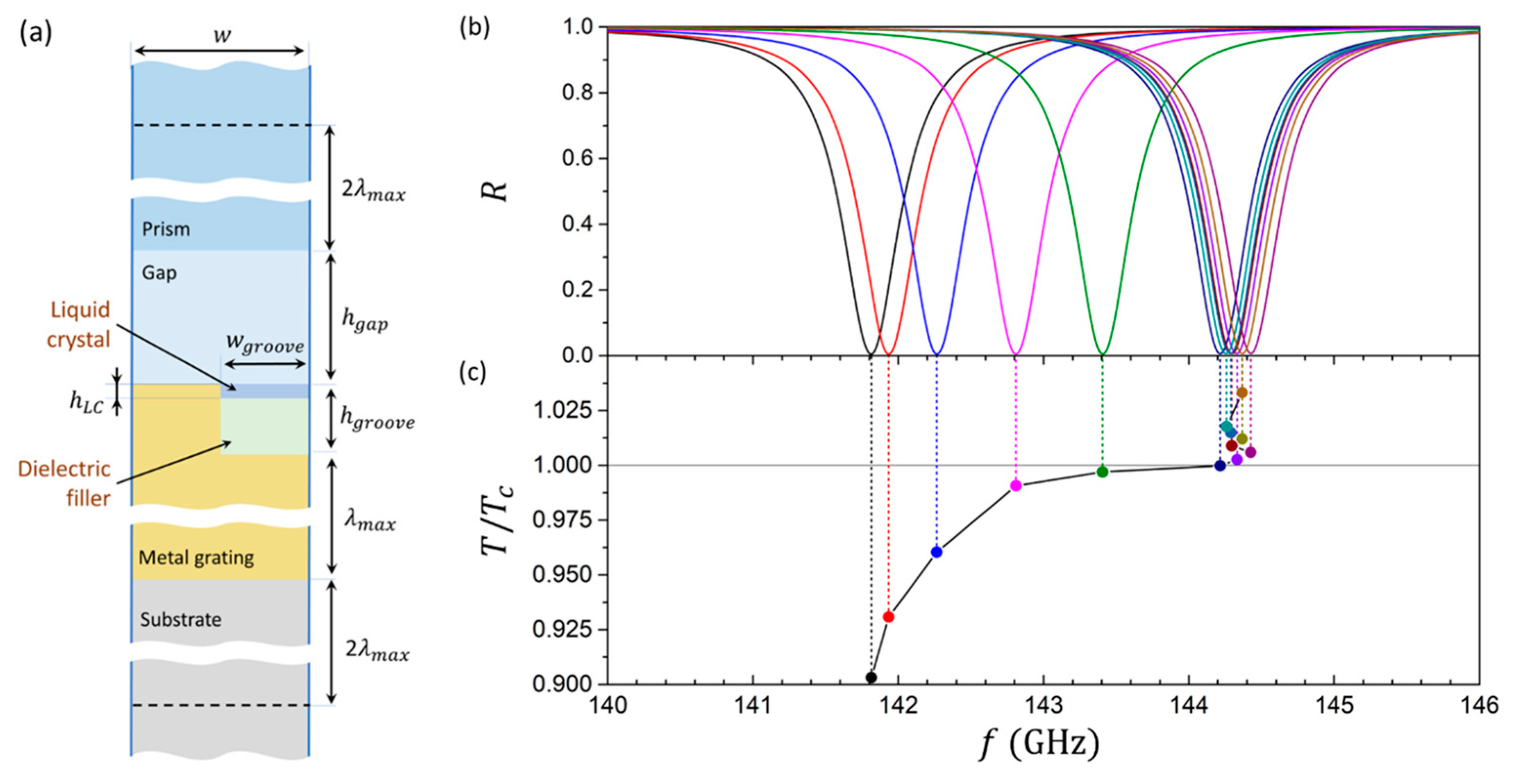
One possible way of achieving an SSPP GHz structure combining a regular-thickness LC cell and deep grooves of the metal grating is to partially fill the grooves with an isotropic dielectric filler, leaving only a thin LC layer on top (Figure 14a). Such an approach allows us to increase the tuning range by more than an order of magnitude (Figure 14b) compared to the shallow grooves structure (Figure 12). The parameters for the calculation presented in Figure 14b are μm, μm, μm, μm, degrees, and μm, with a dielectric filler refractive index of . In such a configuration, the LC turns out to be positioned right at the location of the strong SSPP field enhancement (Figure 15).
Figure 14.
Unit cell of the SSPP structure with partially dielectric-filled grooves (a) and the corresponding reflectance spectra at different temperatures (b). Mapping of the SSPP resonance reflectance dip frequencies to the normalized temperature (c).
Figure 15.
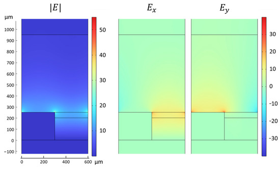
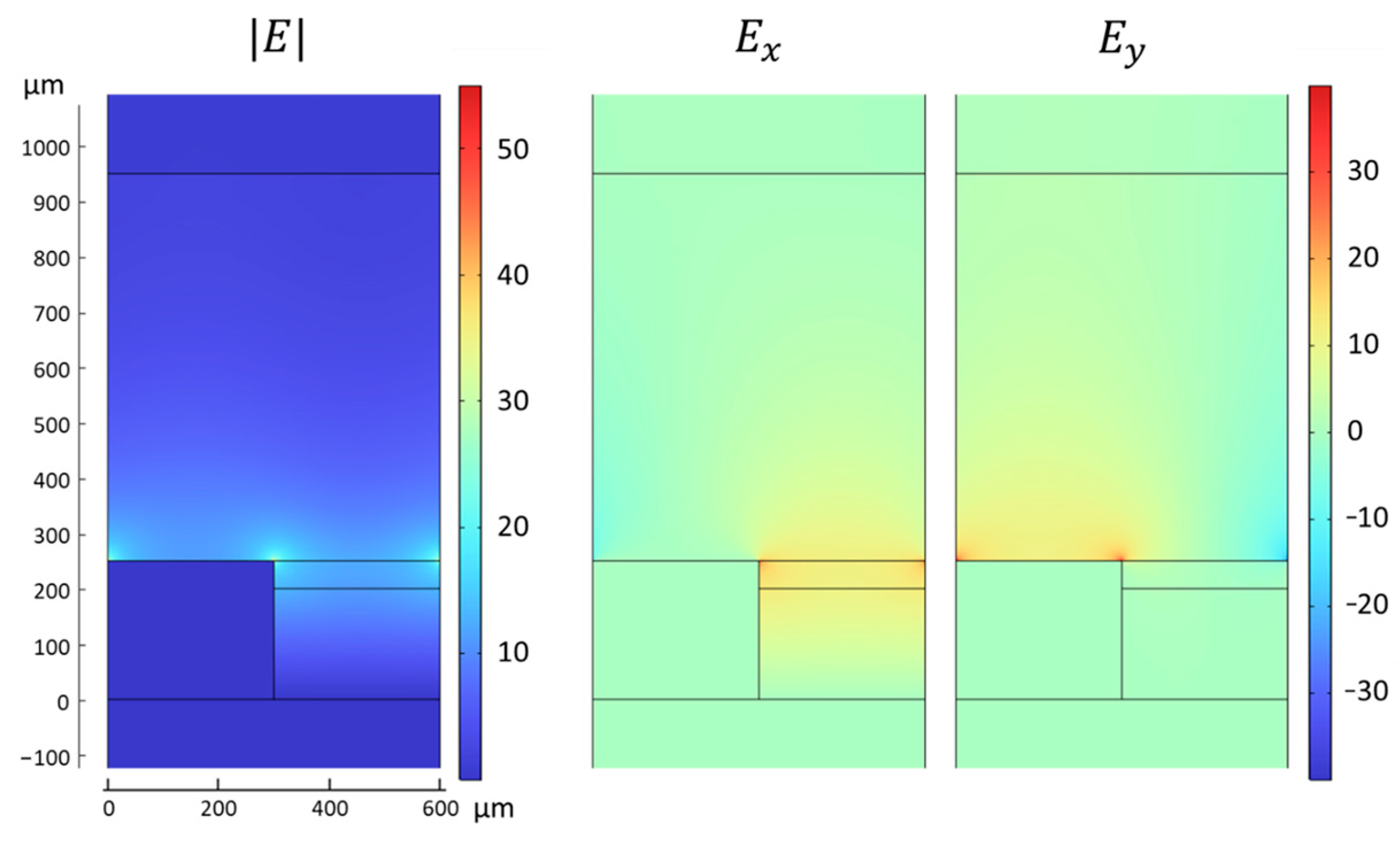
Distribution of the electromagnetic field components in the structure with partially dielectric-filled grooves at the resonance frequency of GHz, corresponding to .
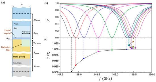
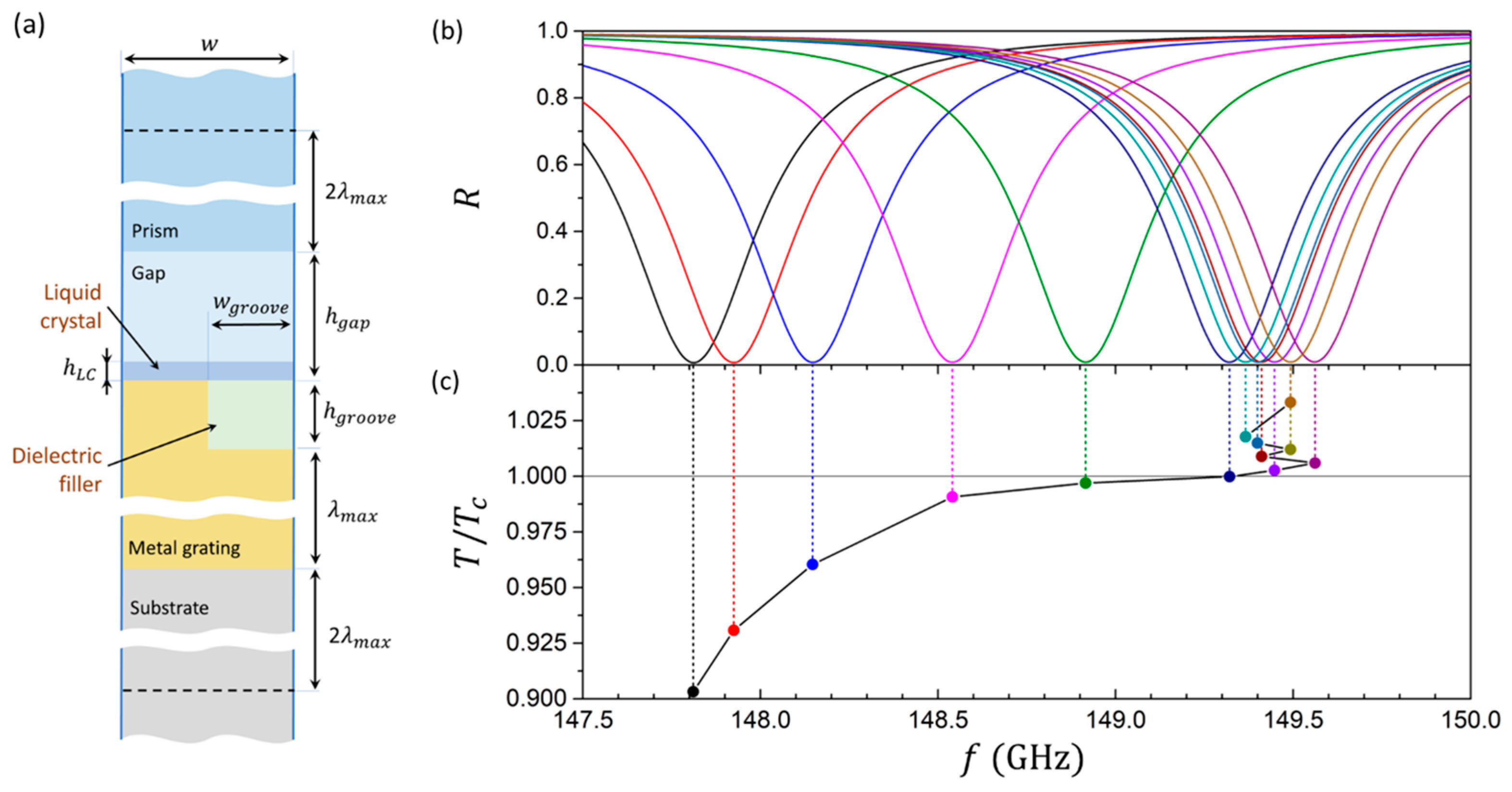
Since decreasing the groove height shifts the SSPP localization upward (Figure 13), positioning the LC layer above the grooves of decreased height is also a promising structural configuration for SSPP tuning. Figure 16a shows the details of such a structure, where the grooves of height μm are filled with a homogeneous dielectric with a refractive index of , while the LC layer with a thickness of μm is positioned directly on top of the grating. The optimal incidence angle of the electromagnetic wave in this structure was found to be degrees.
Figure 16.
Unit cell of the SSPP structure with the LC layer positioned on top of the grating (a) and the corresponding reflectance spectra at different temperatures (b). Mapping of the SSPP resonance reflectance dip frequencies and the normalized temperature (c).
The reflectance spectra for such a structure (Figure 16b,c) remains similar in shape to the previously considered cases, and the depth of the reflectance dips remains close to unity, showing that the presence of the LC layer does not hinder the SSPP excitation. Nevertheless, the SSPP resonance frequency tuning range is substantially lower than in the case of partially dielectric-filled grooves (Figure 14b), spanning 147.8 to 149.5 GHz. Such decreased tuning range is likely the result of LC covering only a small portion of the SSPP electric field localization region (Figure 17). Despite the reduced tuning potential, such a configuration with an LC layer on top of the grating could turn out to be a more convenient solution in practical applications.
Figure 17.
Distribution of the electromagnetic field components in the structure with the LC layer positioned on top of the grating at the resonance frequency of GHz, corresponding to .
5. Discussion
The results presented in this work demonstrate that nematic liquid crystals represent an effective medium for dynamically tuning SSPP resonances in the THz and GHz frequency ranges. The ability to shift the SSPP resonance frequency by reorienting the LC director or inducing a nematic–isotropic phase transition provides a practical route toward active, reconfigurable plasmonic devices. The importance of developing tunable SSPP structures is amplified by the rapidly growing demand for devices operating in the THz and GHz ranges.
Our results show that SSPPs can be tuned efficiently in THz by both director reorientation and temperature-induced nematic–isotropic phase transition, with tuning ranges extending over several hundred gigahertz without a significant degradation in reflectance dip amplitude. In contrast, the LC tuning of the SSPP in the GHz regime presents some challenges, primarily because the SSPP resonance spans hundreds of microns around the metal grating, i.e., over the distances much larger than a typical LC cell thickness. Limiting the LC thickness to the much more commonly used values of less than 50 μm significantly narrows the achievable tuning ranges, as the LC cell covers the area of the electric field enhancement only partially.
A comparison of different structural configurations for the LC tuning of SSPP resonance frequency in THz highlights a set of trade-offs. If the LC-filled grooves of the metal grating are relatively shallow (Figure 12), the SSPP resonance localization shifts toward the dielectric gap, so that the electric field enhancement in the grooves is rather weak (Figure 13), diminishing the SSPP’s sensitivity to the LC director orientation. Such a shallow-grooved SSPP structure is rather poorly suited for LC tuning, as it shows the weakest SSPP confinement among the GHz structures considered in this work. A much more effective tuning can be achieved if the deep grooves are partially filled with an isotropic dielectric layer, so that the LC cells are positioned at the very top of the grooves (Figure 14). In such case, the maximum SSPP electric field enhancement occurs at the top of the grooves, right where the LC cell is positioned. This allows a significantly larger SSPP frequency tuning range of approximately 2.5 GHz. Another promising configuration for tuning SSPPs in GHz is placing the LC layer right on top of the metal grating with dielectric-filled grooves (Figure 16). While the tuning range for such a structure is lower compared to the case of grooves partially filled with a dielectric (Figure 14), such a configuration can potentially be more practical in manufacturing. While LCs in THz and GHz can have significant absorption, in recent years, many LC compounds were designed specifically for THz and sub-THz applications [102,103,104,105,106,107,108,109], ensuring high anisotropy and low absorption in these spectral ranges.
Reorienting the LC director results in a superior tuning range compared to the temperature-induced nematic–isotropic phase transition; however, the presence of metallic sidewalls complicates the LC director reorientation by applying external electric, magnetic, or light fields. Nevertheless, polymer coating the LC cell substrates or doping the LC with a photoactive dye can provide additional control over the LC director orientation using photoalignment [93,94,95,110,111]. In this regard, placing the LC layer above the grating (Figure 16) facilitates the director reorientation. It should also be noted that while no solid substrate is present above the NLC, the NLC–air interface can still impose surface anchoring [112] and therefore influence the director orientation in the cell. As one of the possible practical configurations, a planar LC cell could be reoriented toward the homeotropic state by applying the DC or low-frequency AC voltage between the metal grating and a conductive coating added to the prism’s bottom surface. It should be noted that SSPP frequency was found to be sensitive to the component of the dielectric tensor in the LC cell (see Equation (2)). Therefore, LC director orientation transitions that maximize the change in result in the largest SSPP resonance frequency tuning ranges. Reorienting the LC director from the -planar state to the homeotropic or -planar state provides the maximum tuning range achievable for a given LC anisotropy. In order to maximize the tuning range, a pretilt angle of zero is optimal as it ensures maximum change in the component of the dielectric tensor during director reorientation. However, a small pretilt angle can be useful for achieving a threshold-less director reorientation while having minimal impact on the SSPP frequency tuning range [75]. In case of the thermally induced nematic–isotropic phase transition, the optimal orientation of the LC director in the nematic phase is along the -axis. The presented equation, Equation (2), can be used for quick estimates of how LC director reorientation or the thermo-induced phase transition will shift the SSPP resonance frequency. However, the exact locations and shapes of the reflectance dips, as well as the near-field distributions, can be obtained only through numerical simulations.
The influence of the SSPP electromagnetic field on the LC director can serve as a stabilizing or destabilizing factor for the LC director state. In particular, orientations of the director aligned with the dominant SSPP electric field component are reinforced by the field, whereas the other orientations may become unstable for strong SSPP resonances. This effect is especially pronounced in LC-filled grooves, where the SSPP field distribution is highly confined and largely polarized along the groove axis. Consequently, the -planar LC configuration is stabilized by the SSPP field in the grooves and the isotropic state is largely unaffected, while alternative orientations can be destabilized.
Overall, the studied SSPP structures can find application in reconfigurable THz and GHz photonic devices, such as tunable spectral filters, switches, and perfect metamaterial absorbers. In the THz regime, they are well suited for tunable absorbers and modulators in spectroscopy. In the GHz range, they can be applied as adaptive filters for future 6G communication systems. Nevertheless, several limitations of the work should be noted. SSPP tuning via director reorientation was considered without identifying the optimal configuration of the LC’s boundary conditions, the specifics for applying the orienting external fields, and other design choices, which are the subject of subsequent research. Another important limitation of temperature tuning the SSPP structure should also be acknowledged: the thermally induced nematic–isotropic phase transition is inherently slow compared to electrical LC director reorientation, significantly decreasing the potential tuning rate of such a structure. Nevertheless, temperature tuning of the SSPP structure can be used in applications that do not rely on a fast switch time, for example, in spectroscopy. Additionally, alternative opportunities for thermal tuning are available. For instance, if the LC is doped by dye molecules, the temperature can be changed by shining a light that is absorbed by the dye [113,114]. Alternatively, the orientational scalar order parameter (and, subsequently, the LC anisotropy) can be controlled by trans-cis isomerization in azo-dye molecules added to the LC under ultraviolet illumination [115,116,117,118,119].
In addition to LCs, other tunable materials such as vanadium dioxide (VO2) [120,121,122,123,124,125,126], graphene [127,128,129], and phase-change chalcogenides [130,131] may provide complementary approaches for SSPP tuning. These materials can undergo reversible changes in conductivity or refractive index in response to thermal, electrical, or optical stimuli. Nevertheless, the advantage of LCs lies in their continuous tunability, relatively low loss, and broad operational bandwidth across GHz and THz ranges.
6. Conclusions
We have presented a comprehensive study on the active tuning of spoof surface plasmon polaritons in the GHz and THz frequency ranges using nematic liquid crystals. By integrating LC layers into SSPP-supporting metal gratings, the efficient modulation of SSPP resonance frequencies can be achieved through the reorientation of the LC director under external fields or by inducing a nematic–isotropic phase transition.
In the THz regime, the reorientation of the LC director in SSPP structures allows us to tune the SSPP resonance frequency by up to 200 GHz without degrading the resonance amplitude of the reflectance dips and absorbance peaks. Thermal tuning through the nematic–isotropic phase transition offers a simpler and more practical method for control, achieving similar frequency shifts of up to 150 GHz.
When the structures are scaled to the GHz range, tuning becomes more challenging because the SSPP field extends over much larger distances relative to the thickness of typical LC cells. Nevertheless, practical strategies such as partially filling deep grooves with a dielectric or placing the LC layer above the metal grating can restore the strong coupling between the LC and the SSPP field. These configurations retain high resonance quality while enabling frequency shifts of several GHz, which can be used for creating reconfigurable filters or adaptive components in emerging 6G communication technologies.
Supplementary Materials
The following supporting information can be downloaded at: https://www.mdpi.com/article/10.3390/photonics13060530/s1, Supplementary Material S1: Derivation of the SSPP dispersion relation; Continuous SSPP tuning via director reorientation. Note the different notation and coordinate system used in Supplementary Material S1.
Author Contributions
Conceptualization, I.I.Y., D.R.E. and V.Y.R.; methodology, I.I.Y. and V.Y.R.; software, I.I.Y. and V.Y.R.; validation, I.I.Y., D.R.E. and V.Y.R.; formal analysis, I.I.Y. and V.Y.R.; investigation, I.I.Y. and V.Y.R.; resources, I.I.Y. and V.Y.R.; data curation, I.I.Y. and V.Y.R.; writing—original draft preparation, I.I.Y.; writing—review and editing, I.I.Y., D.R.E. and V.Y.R.; visualization, I.I.Y.; supervision, V.Y.R.; project administration, V.Y.R.; funding acquisition, I.I.Y. All authors have read and agreed to the published version of the manuscript.
Funding
I.I.Y. acknowledges the financial support for this research provided by the Department of Target Training of Taras Shevchenko Kyiv National University of the National Academy of Sciences of Ukraine (Grant No. 5Φ-2026) and the National Research Foundation of Ukraine (Grant No. 2025.07/0147). V.Y.R. acknowledges support by the British Academy/Cara/Leverhulme Research Support Grants.
Data Availability Statement
The original contributions presented in this study are included in the article. Further inquiries can be directed to the corresponding author.
Conflicts of Interest
D.R.E. was employed by Zone 5 Technologies. The remaining authors declare that the research was conducted in the absence of any commercial or financial relationships that could be construed as a potential conflict of interest.
References
- Baker, G.A.; Moore, D.S. Progress in Plasmonic Engineering of Surface-Enhanced Raman-Scattering Substrates toward Ultra-Trace Analysis. Anal. Bioanal. Chem. 2005, 382, 1751–1770. [Google Scholar] [CrossRef] [Scilit] [PubMed]
- Ozbay, E. Plasmonics: Merging Photonics and Electronics at Nanoscale Dimensions. Science 2006, 311, 189–193. [Google Scholar] [CrossRef] [Scilit]
- Ritchie, R.H. Plasma Losses by Fast Electrons in Thin Films. Phys. Rev. 1957, 106, 874. [Google Scholar] [CrossRef] [Scilit]
- Zhang, J.; Zhang, L.; Xu, W. Surface Plasmon Polaritons: Physics and Applications. J. Phys. D Appl. Phys. 2012, 45, 113001. [Google Scholar] [CrossRef] [Scilit]
- Abdulhalim, I. Coupling Configurations between Extended Surface Electromagnetic Waves and Localized Surface Plasmons for Ultrahigh Field Enhancement. Nanophotonics 2018, 7, 1891–1916. [Google Scholar] [CrossRef] [Scilit]
- Ding, F.; Yang, Y.; Deshpande, R.A.; Bozhevolnyi, S.I. A Review of Gap-Surface Plasmon Metasurfaces: Fundamentals and Applications. Nanophotonics 2018, 7, 1129–1156. [Google Scholar] [CrossRef] [Scilit]
- Reshetnyak, V.Y.; Pinkevych, I.; Sluckin, T.; Urbas, A.; Evans, D. Effective Medium Theory for Anisotropic Media with Plasmonic Core-Shell Nanoparticle Inclusions. Eur. Phys. J. Plus 2018, 133, 373. [Google Scholar] [CrossRef] [Scilit]
- Kravets, V.G.; Kabashin, A.V.; Barnes, W.L.; Grigorenko, A.N. Plasmonic Surface Lattice Resonances: A Review of Properties and Applications. Chem. Rev. 2018, 118, 5912–5951. [Google Scholar] [CrossRef] [Scilit] [PubMed]
- Kaliteevski, M.; Iorsh, I.; Brand, S.; Abram, R.A.; Chamberlain, J.M.; Kavokin, A.V.; Shelykh, I.A. Tamm Plasmon-Polaritons: Possible Electromagnetic States at the Interface of a Metal and a Dielectric Bragg Mirror. Phys. Rev. B 2007, 76, 165415. [Google Scholar] [CrossRef] [Scilit]
- Buchnev, O.; Belosludtsev, A.; Reshetnyak, V.; Evans, D.R.; Fedotov, V.A. Observing and Controlling a Tamm Plasmon at the Interface with a Metasurface. Nanophotonics 2020, 9, 897–903. [Google Scholar] [CrossRef] [Scilit]
- Barnes, W.L.; Dereux, A.; Ebbesen, T.W. Surface Plasmon Subwavelength Optics. Nature 2003, 424, 824–830. [Google Scholar] [CrossRef] [Scilit] [PubMed]
- Berini, P.; De Leon, I. Surface Plasmon–Polariton Amplifiers and Lasers. Nat. Photonics 2012, 6, 16–24. [Google Scholar] [CrossRef] [Scilit]
- Krajczewski, J.; Kołątaj, K.; Kudelski, A. Plasmonic Nanoparticles in Chemical Analysis. RSC Adv. 2017, 7, 17559–17576. [Google Scholar] [CrossRef] [Scilit]
- Mejía-Salazar, J.; Oliveira, O.N., Jr. Plasmonic Biosensing: Focus Review. Chem. Rev. 2018, 118, 10617–10625. [Google Scholar] [CrossRef] [Scilit]
- Vo-Dinh, T.; Fales, A.M.; Griffin, G.D.; Khoury, C.G.; Liu, Y.; Ngo, H.; Norton, S.J.; Register, J.K.; Wang, H.-N.; Yuan, H. Plasmonic Nanoprobes: From Chemical Sensing to Medical Diagnostics and Therapy. Nanoscale 2013, 5, 10127–10140. [Google Scholar] [CrossRef] [Scilit]
- Zaccagnini, F.; Radomski, P.; Sforza, M.L.; Ziółkowski, P.; Lim, S.-I.; Jeong, K.-U.; Mikielewicz, D.; Godman, N.P.; Evans, D.R.; Slagle, J.E.; et al. White Light Thermoplasmonic Activated Gold Nanorod Arrays Enable the Photo-Thermal Disinfection of Medical Tools from Bacterial Contamination. J. Mater. Chem. B 2023, 11, 6823–6836. [Google Scholar] [CrossRef] [Scilit]
- Petronella, F.; De Biase, D.; Zaccagnini, F.; Verrina, V.; Lim, S.-I.; Jeong, K.-U.; Miglietta, S.; Petrozza, V.; Scognamiglio, V.; Godman, N.P.; et al. Label-Free and Reusable Antibody-Functionalized Gold Nanorod Arrays for the Rapid Detection of Escherichia Coli Cells in a Water Dispersion. Environ. Sci. Nano 2022, 9, 3343–3360. [Google Scholar] [CrossRef] [Scilit]
- Sforza, M.L.; Petronella, F.; De Biase, D.; Zaccagnini, F.; Lim, S.-I.; Butt, U.A.; d’Alessandro, A.; Godman, N.P.; Evans, D.R.; McConney, M.; et al. Cascade Structured Plasmonic Liquid Crystal Biosensor for the Rapid Detection of Harmful Bacteria Dispersed in Potable Water. Adv. Sens. Res. 2024, 3, 2300201. [Google Scholar] [CrossRef] [Scilit]
- Camden, J.P.; Dieringer, J.A.; Zhao, J.; Van Duyne, R.P. Controlled Plasmonic Nanostructures for Surface-Enhanced Spectroscopy and Sensing. Acc. Chem. Res. 2008, 41, 1653–1661. [Google Scholar] [CrossRef] [Scilit]
- Reshetnyak, V.Y.; Pinkevych, I.P.; Sluckin, T.J.; Evans, D.R. Cloaking by Shells with Radially Inhomogeneous Anisotropic Permittivity. Opt. Express 2016, 24, A21–A32. [Google Scholar] [CrossRef] [Scilit]
- Yang, R.; Lu, Z. Subwavelength Plasmonic Waveguides and Plasmonic Materials. Int. J. Opt. 2012, 2012, 258013. [Google Scholar] [CrossRef] [Scilit]
- Yao, K.; Liu, Y. Plasmonic Metamaterials. Nanotechnol. Rev. 2014, 3, 177–210. [Google Scholar] [CrossRef] [Scilit]
- Huang, J.-A.; Luo, L.-B. Low-Dimensional Plasmonic Photodetectors: Recent Progress and Future Opportunities. Adv. Opt. Mater. 2018, 6, 1701282. [Google Scholar] [CrossRef] [Scilit]
- Oulton, R.F.; Sorger, V.J.; Zentgraf, T.; Ma, R.-M.; Gladden, C.; Dai, L.; Bartal, G.; Zhang, X. Plasmon Lasers at Deep Subwavelength Scale. Nature 2009, 461, 629–632. [Google Scholar] [CrossRef] [Scilit] [PubMed]
- Rappaport, T.S.; Xing, Y.; Kanhere, O.; Ju, S.; Madanayake, A.; Mandal, S.; Alkhateeb, A.; Trichopoulos, G.C. Wireless Communications and Applications above 100 GHz: Opportunities and Challenges for 6G and Beyond. IEEE Access 2019, 7, 78729–78757. [Google Scholar] [CrossRef] [Scilit]
- Kemp, M.C.; Taday, P.; Cole, B.E.; Cluff, J.; Fitzgerald, A.J.; Tribe, W.R. Security Applications of Terahertz Technology. In Proceedings of the Terahertz for Military and Security Applications; SPIE: Bellingham, WA, USA, 2003; Volume 5070, pp. 44–52. [Google Scholar]
- Taylor, Z.D.; Singh, R.S.; Bennett, D.B.; Tewari, P.; Kealey, C.P.; Bajwa, N.; Culjat, M.O.; Stojadinovic, A.; Lee, H.; Hubschman, J.-P.; et al. THz Medical Imaging: In Vivo Hydration Sensing. IEEE Trans. Terahertz Sci. Technol. 2011, 1, 201–219. [Google Scholar] [CrossRef] [Scilit]
- Jiang, W.; Zhou, Q.; He, J.; Habibi, M.A.; Melnyk, S.; El-Absi, M.; Han, B.; Di Renzo, M.; Schotten, H.D.; Luo, F.-L.; et al. Terahertz Communications and Sensing for 6G and beyond: A Comprehensive Review. IEEE Commun. Surv. Tutor. 2024, 26, 2326–2381. [Google Scholar] [CrossRef] [Scilit]
- Bera, R. Generation, Detection and Analysis of Sub-Terahertz Over the Air (OTA) Test Bed for 6G Mobile Communication Use Cases. In Generation, Detection and Processing of Terahertz Signals; Springer: Berlin/Heidelberg, Germany, 2021; pp. 97–122. [Google Scholar]
- Shibayama, J.; Uchizono, Y.; Ozaki, S.; Yamauchi, J.; Nakano, H. Treatment of Metal for the FDTD Analysis of Terahertz Devices. Opt. Quantum Electron. 2014, 46, 345–356. [Google Scholar] [CrossRef] [Scilit]
- Zhang, X.; Xu, Q.; Xia, L.; Li, Y.; Gu, J.; Tian, Z.; Ouyang, C.; Han, J.; Zhang, W. Terahertz Surface Plasmonic Waves: A Review. Adv. Photonics 2020, 2, 014001. [Google Scholar] [CrossRef] [Scilit]
- Garcia-Vidal, F.J.; Fernández-Domínguez, A.I.; Martin-Moreno, L.; Zhang, H.C.; Tang, W.; Peng, R.; Cui, T.J. Spoof Surface Plasmon Photonics. Rev. Mod. Phys. 2022, 94, 025004. [Google Scholar] [CrossRef] [Scilit]
- Garcia-Vidal, F.J.; Martin-Moreno, L.; Pendry, J.B. Surfaces with Holes in Them: New Plasmonic Metamaterials. J. Opt. A Pure Appl. Opt. 2005, 7, S97–S101. [Google Scholar] [CrossRef] [Scilit]
- Joy, S.R.; Yu, H.; Mazumder, P. Properties of Spoof Plasmon in Thin Structures. Proc. R. Soc. A 2018, 474, 20180205. [Google Scholar] [CrossRef] [Scilit] [PubMed]
- Garcia-Vidal, F.; Martin-Moreno, L. Transmission and Focusing of Light in One-Dimensional Periodically Nanostructured Metals. Phys. Rev. B 2002, 66, 155412. [Google Scholar] [CrossRef] [Scilit]
- Sun, S.; He, Q.; Xiao, S.; Xu, Q.; Li, X.; Zhou, L. Gradient-Index Meta-Surfaces as a Bridge Linking Propagating Waves and Surface Waves. Nat. Mater. 2012, 11, 426–431. [Google Scholar] [CrossRef] [Scilit]
- Kushiyama, Y.; Arima, T.; Uno, T. Experimental Verification of Spoof Surface Plasmons in Wire Metamaterials. Opt. Express 2012, 20, 18238–18247. [Google Scholar] [CrossRef] [Scilit]
- Kretschmann, E. Die Bestimmung Optischer Konstanten von Metallen Durch Anregung von Oberflächenplasmaschwingungen. Z. Für Phys. A Hadron. Nucl. 1971, 241, 313–324. [Google Scholar] [CrossRef] [Scilit]
- Otto, A. Excitation of Nonradiative Surface Plasma Waves in Silver by the Method of Frustrated Total Reflection. Z. Für Phys. A Hadron. Nucl. 1968, 216, 398–410. [Google Scholar] [CrossRef] [Scilit]
- Yin, J.-Y.; Yin, T.; Du, X.Y.; Ning, Y.; Guo, L.-X. Efficient Conversion from Spoof Surface Plasmon Polaritons to Radiation Mode. Appl. Opt. 2021, 60, 3374–3379. [Google Scholar] [CrossRef] [Scilit]
- Li, Z.; Liu, L.; Xu, B.; Ning, P.; Chen, C.; Xu, J.; Chen, X.; Gu, C.; Qing, Q. High-Contrast Gratings Based Spoof Surface Plasmons. Sci. Rep. 2016, 6, 21199. [Google Scholar] [CrossRef] [Scilit]
- Pan, J.; Wang, J.; Qiu, T.; Pang, Y.; Li, Y.; Zhang, J.; Qu, S. Circulation of Spoof Surface Plasmon Polaritons: Implementation and Verification. AIP Adv. 2018, 8, 055002. [Google Scholar] [CrossRef] [Scilit]
- Wang, S.; Chen, K.; Zhao, J.; Feng, Y. Tunable Non-Diffraction Spoof Surface Plasmon Polaritons with Liquid Crystal Terahertz Metasurface. In Proceedings of the 2021 IEEE MTT-S International Microwave Workshop Series on Advanced Materials and Processes for RF and THz Applications (IMWS-AMP); IEEE: Piscataway, NJ, USA, 2021; pp. 136–138. [Google Scholar]
- Kianinejad, A.; Chen, Z.N.; Qiu, C.-W. Design and Modeling of Spoof Surface Plasmon Modes-Based Microwave Slow-Wave Transmission Line. IEEE Trans. Microw. Theory Tech. 2015, 63, 1817–1825. [Google Scholar] [CrossRef] [Scilit]
- Hu, M.Z.; Zhang, H.C.; Yin, J.Y.; Ding, Z.; Liu, J.F.; Tang, W.X.; Cui, T.J. Ultra-Wideband Filtering of Spoof Surface Plasmon Polaritons Using Deep Subwavelength Planar Structures. Sci. Rep. 2016, 6, 37605. [Google Scholar] [CrossRef] [Scilit] [PubMed]
- He, P.H.; Zhang, H.C.; Gao, X.; Yun, L.; Tang, W.X.; Lu, J.; Zhang, L.P.; Cui, T.J. A Novel Spoof Surface Plasmon Polariton Structure to Reach Ultra-Strong Field Confinements. Opto-Electron. Adv. 2019, 2, 190001. [Google Scholar] [CrossRef] [Scilit]
- Zhang, J.; Liao, Z.; Luo, Y.; Shen, X.; Maier, S.A.; Cui, T.J. Spoof Plasmon Hybridization. Laser Photonics Rev. 2017, 11, 1600191. [Google Scholar] [CrossRef] [Scilit]
- Ng, B.; Hanham, S.M.; Wu, J.; Fernández-Domínguez, A.I.; Klein, N.; Liew, Y.F.; Breese, M.B.; Hong, M.; Maier, S.A. Broadband Terahertz Sensing on Spoof Plasmon Surfaces. Acs Photonics 2014, 1, 1059–1067. [Google Scholar] [CrossRef] [Scilit]
- Ng, B.; Wu, J.; Hanham, S.M.; Fernández-Domínguez, A.I.; Klein, N.; Liew, Y.F.; Breese, M.B.; Hong, M.; Maier, S.A. Spoof Plasmon Surfaces: A Novel Platform for THz Sensing. Adv. Opt. Mater. 2013, 1, 543–548. [Google Scholar] [CrossRef] [Scilit]
- Jidi, L.; Cao, X.; Gao, J.; Li, T.; Yang, H.; Li, S. Ultra-Wideband Absorber for Electromagnetic Waves under Large Incident Angle Based on Spoof Surface Plasmon Polaritons. Opt. Mater. Express 2021, 11, 3917–3929. [Google Scholar] [CrossRef] [Scilit]
- Jaiswal, R.K.; Pandit, N.; Pathak, N.P. Spoof Surface Plasmon Polaritons Based Reconfigurable Band-Pass Filter. IEEE Photonics Technol. Lett. 2018, 31, 218–221. [Google Scholar] [CrossRef] [Scilit]
- Liu, S.; Hu, J.; Zhang, Y.; Zheng, Z.; Liu, Y.; Xu, R.; Xue, Q. 1 THz Micromachined Waveguide Band-Pass Filter. J. Infrared Millim. Terahertz Waves 2016, 37, 435–447. [Google Scholar] [CrossRef] [Scilit]
- Ye, L.; Xiao, Y.; Liu, Y.; Zhang, L.; Cai, G.; Liu, Q.H. Strongly Confined Spoof Surface Plasmon Polaritons Waveguiding Enabled by Planar Staggered Plasmonic Waveguides. Sci. Rep. 2016, 6, 38528. [Google Scholar] [CrossRef] [Scilit] [PubMed]
- Nikitin, A.; Vitko, V.; Ustinov, A.; Kalinikos, B. Microwave Tunable Devices on the YIG-VO2 Structures. J. Phys. Conf. Ser. 2019, 1400, 044001. [Google Scholar] [CrossRef] [Scilit]
- Dias, E.J.; Peres, N. Controlling Spoof Plasmons in a Metal Grating Using Graphene Surface Plasmons. ACS Photonics 2017, 4, 3071–3080. [Google Scholar] [CrossRef] [Scilit]
- Du, H.; Zhang, X.; Liu, J.; Meng, H.; Feng, H.; Yang, S.; Gao, Y. Graphene-Based Switchable and Tunable Selective Absorption Metasurface. J. Nanophotonics 2025, 19, 016009. [Google Scholar] [CrossRef] [Scilit]
- Goldflam, M.D.; Ruiz, I.; Howell, S.W.; Wendt, J.R.; Sinclair, M.B.; Peters, D.W.; Beechem, T.E. Tunable Dual-Band Graphene-Based Infrared Reflectance Filter. Opt. Express 2018, 26, 8532–8541. [Google Scholar] [CrossRef] [Scilit] [PubMed]
- Yang, D.-K.; Wu, S.-T. Fundamentals of Liquid Crystal Devices; John Wiley & Sons: Hoboken, NJ, USA, 2014. [Google Scholar]
- De Gennes, P.-G.; Prost, J. The Physics of Liquid Crystals; Oxford University Press: Oxford, UK, 1993. [Google Scholar]
- Abdulhalim, I. Liquid Crystal Active Nanophotonics and Plasmonics: From Science to Devices. J. Nanophotonics 2012, 6, 061001. [Google Scholar] [CrossRef] [Scilit]
- Yakovkin, I.; Reshetnyak, V. Liquid Crystal-Enabled Tunability of Yagi-Uda Antenna Resonant Properties. J. Opt. Microsyst. 2023, 3, 041203. [Google Scholar] [CrossRef] [Scilit]
- Reshetnyak, V.Y.; Pinkevych, I.P.; McConney, M.E.; Bunning, T.J.; Evans, D.R. Tamm Plasmons: Properties, Applications, and Tuning with Help of Liquid Crystals. Crystals 2025, 15, 138. [Google Scholar] [CrossRef] [Scilit]
- Ma, J.; Choi, J.; Park, S.; Kong, I.; Kim, D.; Lee, C.; Youn, Y.; Hwang, M.; Oh, S.; Hong, W.; et al. Liquid Crystals for Advanced Smart Devices with Microwave and Millimeter-Wave Applications: Recent Progress for next-Generation Communications. Adv. Mater. 2023, 35, 2302474. [Google Scholar] [CrossRef] [Scilit]
- Cano, H.P.Z.; Zaharis, Z.D.; Yioultsis, T.V.; Kantartzis, N.V.; Lazaridis, P.I. Pattern Reconfigurable Antennas at Millimeter-Wave Frequencies: A Comprehensive Survey. IEEE Access 2022, 10, 83029–83042. [Google Scholar] [CrossRef] [Scilit]
- Yakovkin, I.; Reshetnyak, V. Controlling Plasmon Resonance of Gold and Silver Nanoparticle Arrays with Help of Liquid Crystal. Photonics 2023, 10, 1088. [Google Scholar] [CrossRef] [Scilit]
- Humar, M.; Ravnik, M.; Pajk, S.; Muševič, I. Electrically Tunable Liquid Crystal Optical Microresonators. Nat. Photonics 2009, 3, 595–600. [Google Scholar] [CrossRef] [Scilit]
- Abass, A.; Rodriguez, S.R.-K.; Ako, T.; Aubert, T.; Verschuuren, M.; Van Thourhout, D.; Beeckman, J.; Hens, Z.; Gómez Rivas, J.; Maes, B. Active Liquid Crystal Tuning of Metallic Nanoantenna Enhanced Light Emission from Colloidal Quantum Dots. Nano Lett. 2014, 14, 5555–5560. [Google Scholar] [CrossRef] [Scilit]
- Yakovkin, I.; Ledney, M. Voltage-Controlled Surface Plasmon in a Flexoelectric Nematic Liquid Crystal Cell. Liq. Cryst. 2025, 52, 502–516. [Google Scholar] [CrossRef] [Scilit]
- Ledney, M.; Tarnavskyy, O.; Lesiuk, A.; Reshetnyak, V.Y. Interaction of Electromagnetic Waves in Nematic Waveguide. Mol. Cryst. Liq. Cryst. 2016, 638, 1–16. [Google Scholar] [CrossRef] [Scilit]
- Bortolozzo, U.; Residori, S.; Huignard, J. Beam Coupling in Photorefractive Liquid Crystal Light Valves. J. Phys. D Appl. Phys. 2008, 41, 224007. [Google Scholar] [CrossRef] [Scilit]
- Buchnev, O.; Dyadyusha, A.; Kaczmarek, M.; Reshetnyak, V.; Reznikov, Y. Enhanced Two-Beam Coupling in Colloids of Ferroelectric Nanoparticles in Liquid Crystals. J. Opt. Soc. Am. B 2007, 24, 1512–1516. [Google Scholar] [CrossRef] [Scilit]
- Reshetnyak, V.Y.; Pinkevych, I.; Cook, G.; Evans, D.; Sluckin, T. Two-Beam Energy Exchange in a Hybrid Photorefractive-Flexoelectric Liquid-Crystal Cell. Phys. Rev. E—Stat. Nonlinear Soft Matter Phys. 2010, 81, 031705. [Google Scholar] [CrossRef] [Scilit]
- Cook, G.; Glushchenko, A.; Reshetnyak, V.; Griffith, A.; Saleh, M.; Evans, D. Nanoparticle Doped Organic-Inorganic Hybrid Photorefractives. Opt. Express 2008, 16, 4015–4022. [Google Scholar] [CrossRef] [Scilit]
- Garbovskiy, Y.; Zagorodnii, V.; Krivosik, P.; Lovejoy, J.; Camley, R.; Celinski, Z.; Glushchenko, A.; Dziaduszek, J.; Dąbrowski, R. Liquid Crystal Phase Shifters at Millimeter Wave Frequencies. J. Appl. Phys. 2012, 111, 054504. [Google Scholar] [CrossRef] [Scilit]
- Yakovkin, I.I.; Reshetnyak, V.Y.; Bunning, T.J.; Evans, D.R. Tunable THz Absorbers Based on LC-Tuned Yagi-Uda Antennas. Liq. Cryst. 2024, 51, 2241–2251. [Google Scholar] [CrossRef] [Scilit]
- Liu, L.; Langley, R. Liquid Crystal Tunable Microstrip Patch Antenna. Electron. Lett. 2008, 44, 1179–1181. [Google Scholar] [CrossRef] [Scilit]
- Reshetnyak, V.Y.; Pinkevych, I.P.; Zadorozhnii, V.I.; Evans, D.R. Liquid Crystal Control of Surface Plasmon Resonance Sensor Based on Nanorods. Mol. Cryst. Liq. Cryst. 2015, 613, 110–120. [Google Scholar] [CrossRef] [Scilit]
- Reshetnyak, V.Y.; Zadorozhnii, V.I.; Pinkevych, I.P.; Evans, D.R. Liquid Crystal Control of the Plasmon Resonances at Terahertz Frequencies in Graphene Microribbon Gratings. Phys. Rev. E 2017, 96, 022703. [Google Scholar] [CrossRef] [Scilit]
- Mysliwiec, J.; Szukalska, A.; Szukalski, A.; Sznitko, L. Liquid Crystal Lasers: The Last Decade and the Future. Nanophotonics 2021, 10, 2309–2346. [Google Scholar] [CrossRef] [Scilit]
- Yakovkin, I.; Ledney, M.; Reshetnyak, V.Y.; Pakamoryte, I.; Hands, P.J. Modeling of Laser Generation in a Fabry–Pérot-Tamm Structure with a Nematic Liquid Crystal Layer. J. Appl. Phys. 2024, 135, 213102. [Google Scholar] [CrossRef] [Scilit]
- Blinov, L.M.; Cipparrone, G.; Mazzulla, A.; Pagliusi, P.; Lazarev, V.V.; Palto, S.P. Simple Voltage Tunable Liquid Crystal Laser. Appl. Phys. Lett. 2007, 90, 131103. [Google Scholar] [CrossRef] [Scilit]
- D’yakonov, M. New Type of Electromagnetic Wave Propagating at an Interface. Zh. Eksp. Teor. Fiz 1988, 94, 119–123. [Google Scholar]
- Ding, C.; Meng, F.-Y.; Jin, T.; Lv, J.-F.; Mu, H.-L.; Wu, Q. Tunable Balanced Liquid Crystal Phase Shifter Based on Spoof Surface Plasmon Polaritons with Common-Mode Suppression. Liq. Cryst. 2020, 47, 1612–1623. [Google Scholar] [CrossRef] [Scilit]
- Zhao, W.; Ju, D.; Jiang, Y. Efficient Localization of Terahertz Waves within a Gradient Dielectric-Filled Metallic Grating. Appl. Phys. Express 2014, 7, 124301. [Google Scholar] [CrossRef] [Scilit]
- Song, K.; Mazumder, P. Active Terahertz Spoof Surface Plasmon Polariton Switch Comprising the Perfect Conductor Metamaterial. IEEE Trans. Electron Devices 2009, 56, 2792–2799. [Google Scholar] [CrossRef] [Scilit]
- Hagemann, H.-J.; Gudat, W.; Kunz, C. Optical Constants from the Far Infrared to the X-Ray Region: Mg, Al, Cu, Ag, Au, Bi, C, and Al2O3. J. Opt. Soc. Am. 1975, 65, 742–744. [Google Scholar] [CrossRef] [Scilit]
- Pan, C.-L.; Pan, R.-P. Recent Progress in Liquid Crystal THz Optics. Liq. Cryst. Mater. Devices Appl. XI 2006, 6135, 93–105. [Google Scholar]
- Arakawa, Y.; Kang, S.; Tsuji, H.; Watanabe, J.; Konishi, G. The Design of Liquid Crystalline Bistolane-Based Materials with Extremely High Birefringence. RSC Adv. 2016, 6, 92845–92851. [Google Scholar] [CrossRef] [Scilit]
- Arakawa, Y.; Nakajima, S.; Ishige, R.; Uchimura, M.; Kang, S.; Konishi, G.; Watanabe, J. Synthesis of Diphenyl-Diacetylene-Based Nematic Liquid Crystals and Their High Birefringence Properties. J. Mater. Chem. 2012, 22, 8394–8398. [Google Scholar] [CrossRef] [Scilit]
- Chodorow, U.; Parka, J.; Garbat, K.; Pałka, N.; Czupryński, K. Spectral Investigation of Nematic Liquid Crystals with High Optical Anisotropy at THz Frequency Range. Phase Transit. 2012, 85, 337–344. [Google Scholar] [CrossRef] [Scilit]
- Ji, Y.-Y.; Fan, F.; Xu, S.-T.; Yu, J.-P.; Liu, Y.; Wang, X.-H.; Chang, S.-J. Terahertz Dielectric Anisotropy Enhancement in Dual-Frequency Liquid Crystal Induced by Carbon Nanotubes. Carbon 2019, 152, 865–872. [Google Scholar] [CrossRef] [Scilit]
- Wang, L.; Xiao, R.-W.; Ge, S.-J.; Shen, Z.-X.; Lu, P.; Hu, W.; Lu, Y.-Q. Research Progress of Terahertz Liquid Crystal Materials and Devices. Acta Phys. Sin. 2019, 68, 084205. [Google Scholar] [CrossRef] [Scilit]
- Chigrinov, V.G.; Kozenkov, V.M.; Kwok, H.-S. Photoalignment of Liquid Crystalline Materials: Physics and Applications; John Wiley & Sons: Hoboken, NJ, USA, 2008. [Google Scholar]
- Reznikov, Y.; Ostroverkhova, O.; Singer, K.D.; Kim, J.-H.; Kumar, S.; Lavrentovich, O.; Wang, B.; West, J.L. Photoalignment of Liquid Crystals by Liquid Crystals. Phys. Rev. Lett. 2000, 84, 1930. [Google Scholar] [CrossRef] [Scilit] [PubMed]
- Ichimura, K. Photoalignment of Liquid-Crystal Systems. Chem. Rev. 2000, 100, 1847–1874. [Google Scholar] [CrossRef] [Scilit] [PubMed]
- Haba, O.; Hiratsuka, D.; Shiraiwa, T.; Funakoshi, N.; Awano, H.; Koda, T.; Takahashi, T.; Yonetake, K.; Kwak, M.; Momoi, Y.; et al. Homeotropic Orientation of Nematic Liquid Crystals Induced by Dissolving Polypropyleneimine Dendrimer Having Peripheral Mesogens. Opt. Mater. Express 2014, 4, 934–943. [Google Scholar] [CrossRef] [Scilit]
- Hirankittiwong, P.; Chattham, N.; Limtrakul, J.; Haba, O.; Yonetake, K.; Eremin, A.; Stannarius, R.; Takezoe, H. Optical Manipulation of the Nematic Director Field around Microspheres Covered with an Azo-Dendrimer Monolayer. Opt. Express 2014, 22, 20087–20093. [Google Scholar] [CrossRef] [Scilit]
- Brake, J.M.; Mezera, A.D.; Abbott, N.L. Effect of Surfactant Structure on the Orientation of Liquid Crystals at Aqueous- Liquid Crystal Interfaces. Langmuir 2003, 19, 6436–6442. [Google Scholar] [CrossRef] [Scilit]
- Lockwood, N.A.; de Pablo, J.J.; Abbott, N.L. Influence of Surfactant Tail Branching and Organization on the Orientation of Liquid Crystals at Aqueous- Liquid Crystal Interfaces. Langmuir 2005, 21, 6805–6814. [Google Scholar] [CrossRef] [Scilit] [PubMed]
- Yang, C.-S.; Lin, C.-J.; Pan, R.-P.; Que, C.T.; Yamamoto, K.; Tani, M.; Pan, C.-L. The Complex Refractive Indices of the Liquid Crystal Mixture E7 in the Terahertz Frequency Range. J. Opt. Soc. Am. B 2010, 27, 1866–1873. [Google Scholar] [CrossRef] [Scilit]
- Inoue, Y.; Kubo, H.; Shikada, T.; Moritake, H. Ideal Polymer-LC Composite Structure for Terahertz Phase Shifters. Macromol. Mater. Eng. 2019, 304, 1800766. [Google Scholar] [CrossRef] [Scilit]
- Chodorow, U.; Parka, J.; Chojnowska, O. Liquid Crystal Materials in THz Technologies. Photonics Lett. Pol. 2012, 4, 112–114. [Google Scholar] [CrossRef] [Scilit]
- Zografopoulos, D.; Prokopidis, K.; Dąbrowski, R.; Beccherelli, R. Time-Domain Modeling of Dispersive and Lossy Liquid-Crystals for Terahertz Applications. Opt. Mater. Express 2014, 4, 449–457. [Google Scholar] [CrossRef] [Scilit]
- Park, H.; Parrott, E.P.; Fan, F.; Lim, M.; Han, H.; Chigrinov, V.G.; Pickwell-MacPherson, E. Evaluating Liquid Crystal Properties for Use in Terahertz Devices. Opt. Express 2012, 20, 11899–11905. [Google Scholar] [CrossRef] [Scilit]
- Zheng, A.; Xia, X.; Gao, S.; Yang, J.; Lu, H.; Deng, G.; Yin, Z. Dielectric properties of two high birefringence liquid crystal mixtures in the Sub-THz band. Liq. Cryst. 2020, 47, 83–88. [Google Scholar] [CrossRef] [Scilit]
- Wang, L.; Wang, Y.; Zong, G.; Hu, W.; Lu, Y. Liquid Crystal Based Tunable Terahertz Metadevices. J. Mater. 2025, 11, 100888. [Google Scholar] [CrossRef] [Scilit]
- Sielezin, K.; Kowerdziej, R.; Chodorow, U.; Olifierczuk, M.; Parka, J. Simulations of Spectra and Some Physical Attributes of Specific Homologous Series of Nematic Liquid Crystals in the Range of 0.4–7.6 THz. Photonics Lett. Pol. 2025, 17, 82–84. [Google Scholar] [CrossRef] [Scilit]
- Parka, J.; Sielezin, K. 0.3–10.0 THz Spectra for Chosen Liquid Crystal Molecules–Simulation and Physical Properties. Mol. Cryst. Liq. Cryst. 2017, 657, 66–71. [Google Scholar] [CrossRef] [Scilit]
- Jiménez-Sáez, A.; Späth, M.; Neuder, R.; Jakoby, R. Liquid Crystal Goes RF: From Gigahertz to Terahertz. IEEE Microw. Mag. 2025, 26, 82–102. [Google Scholar] [CrossRef] [Scilit]
- Gerus, I.; Glushchenko, A.; Kwon, S.-B.; Reshetnyak, V.; Reznikov, Y. Anchoring of a Liquid Crystal on a Photoaligning Layer with Varying Surface Morphology. Liq. Cryst. 2001, 28, 1709–1713. [Google Scholar] [CrossRef] [Scilit]
- Shteyner, E.A.; Srivastava, A.K.; Chigrinov, V.G.; Kwok, H.-S.; Afanasyev, A.D. Submicron-Scale Liquid Crystal Photo-Alignment. Soft Matter 2013, 9, 5160–5165. [Google Scholar] [CrossRef] [Scilit]
- Xue, X.; Berteloot, B.; Stebryte, M.; Neyts, K.; Beeckman, J. Role of Homeotropic Alignment Strength at the Air Interface of Polymerized Liquid Crystal Layers. Opt. Mater. Express 2021, 11, 4036–4050. [Google Scholar] [CrossRef] [Scilit]
- Shcherbinin, D.; Glukharev, D.A.; Rudyi, S.; Piven, A.; Orlova, T.; Śliwa, I.; Zakharov, A. Light-Induced Heating of Microsized Nematic Volumes. Crystals 2025, 15, 822. [Google Scholar] [CrossRef] [Scilit]
- Jagodič, U.; Ryzhkova, A.; Muševič, I. Localised Opto-Thermal Response of Nematic Liquid Crystal to Laser Light. Liq. Cryst. 2019, 46, 1117–1126. [Google Scholar] [CrossRef] [Scilit]
- Paoloni, S.; Mercuri, F.; Zammit, U.; Orazi, N. Dynamics of the Isotropic to Nematic Phase Conversion Induced by the Cis to Trans Isomerization in a Liquid Crystalline Azobenzene. J. Mol. Liq. 2025, 434, 127985. [Google Scholar] [CrossRef] [Scilit]
- Hogan, P.; Tajbakhsh, A.; Terentjev, E. UV Manipulation of Order and Macroscopic Shape in Nematic Elastomers. Phys. Rev. E 2002, 65, 041720. [Google Scholar] [CrossRef] [Scilit]
- Kim, N.; Li, Q.; Kyu, T. Effect of Trans-Cis Photoisomerization on Phase Equilibria and Phase Transition of Liquid-Crystalline Azobenzene Chromophore and Its Blends with Reactive Mesogenic Diacrylate. Phys. Rev. E—Stat. Nonlinear Soft Matter Phys. 2011, 83, 031702. [Google Scholar] [CrossRef] [Scilit]
- Soulé, E.R. Thermodynamic Model of Phase Transitions Induced by Cis-Trans Thermal-and Photo-Isomerization of Azobenzenes. Chem. Phys. Lett. 2022, 794, 139503. [Google Scholar] [CrossRef] [Scilit]
- Barbero, G.; Evangelista, L. Concentration Dependence of the Scalar Order Parameter in Liquid-Crystalline Systems with Variable Molecular Shape. Phys. Rev. E 2000, 61, 2749. [Google Scholar] [CrossRef] [Scilit]
- Song, Z.; Wang, K.; Li, J.; Liu, Q.H. Broadband Tunable Terahertz Absorber Based on Vanadium Dioxide Metamaterials. Opt. Express 2018, 26, 7148–7154. [Google Scholar] [CrossRef] [Scilit]
- Currie, M.; Mastro, M.A.; Wheeler, V.D. Characterizing the Tunable Refractive Index of Vanadium Dioxide. Opt. Mater. Express 2017, 7, 1697–1707. [Google Scholar] [CrossRef] [Scilit]
- Bartenev, A.; George, D.M. Recent Advances in Tunable Antennas Using Phase Change Materials. J. Electromagn. Waves Appl. 2026, 40, 219–238. [Google Scholar] [CrossRef] [Scilit]
- King, J.; Wan, C.; Park, T.J.; Deshpande, S.; Zhang, Z.; Ramanathan, S.; Kats, M.A. Electrically Tunable VO2–Metal Metasurface for Mid-Infrared Switching, Limiting and Nonlinear Isolation. Nat. Photonics 2024, 18, 74–80. [Google Scholar] [CrossRef] [Scilit]
- Wang, Y.; Gu, Y.; Liu, F.; Chen, L.; Wang, X.; Ji, K. Tunable Broadband Terahertz Absorber Based on a Simple Design of a Vanadium Dioxide Resonator. J. Opt. Soc. Am. A 2025, 42, 309–314. [Google Scholar] [CrossRef] [Scilit]
- Cormier, P.; Son, T.V.; Thibodeau, J.; Doucet, A.; Truong, V.-V.; Haché, A. Vanadium Dioxide as a Material to Control Light Polarization in the Visible and near Infrared. Opt. Commun. 2017, 382, 80–85. [Google Scholar] [CrossRef] [Scilit]
- Sun, Y.; Narayanachari, K.; Wan, C.; Sun, X.; Wang, H.; Cooley, K.A.; Mohney, S.E.; White, D.; Duwel, A.; Kats, M.A.; et al. Thermally Tunable VO2-SiO2 Nanocomposite Thin-Film Capacitors. J. Appl. Phys. 2018, 123, 114103. [Google Scholar] [CrossRef] [Scilit]
- Cheng, J.; Fan, F.; Chang, S. Recent Progress on Graphene-Functionalized Metasurfaces for Tunable Phase and Polarization Control. Nanomaterials 2019, 9, 398. [Google Scholar] [CrossRef] [Scilit] [PubMed]
- Zhang, Y.; Feng, Y.; Zhao, J.; Jiang, T.; Zhu, B. Terahertz Beam Switching by Electrical Control of Graphene-Enabled Tunable Metasurface. Sci. Rep. 2017, 7, 14147. [Google Scholar] [CrossRef] [Scilit] [PubMed]
- Huidobro, P.A.; Kraft, M.; Maier, S.A.; Pendry, J.B. Graphene as a Tunable Anisotropic or Isotropic Plasmonic Metasurface. ACS Nano 2016, 10, 5499–5506. [Google Scholar] [CrossRef] [Scilit]
- Ding, F.; Yang, Y.; Bozhevolnyi, S.I. Dynamic Metasurfaces Using Phase-Change Chalcogenides. Adv. Opt. Mater. 2019, 7, 1801709. [Google Scholar] [CrossRef] [Scilit]
- De Galarreta, C.R.; Carrillo, S.G.; Au, Y.; Gemo, E.; Trimby, L.; Shields, J.; Humphreys, E.; Faneca, J.; Cai, L.; Baldycheva, A.; et al. Tunable Optical Metasurfaces Enabled by Chalcogenide Phase-Change Materials: From the Visible to the THz. J. Opt. 2020, 22, 114001. [Google Scholar] [CrossRef] [Scilit]
Disclaimer/Publisher’s Note: The statements, opinions and data contained in all publications are solely those of the individual author(s) and contributor(s) and not of MDPI and/or the editor(s). MDPI and/or the editor(s) disclaim responsibility for any injury to people or property resulting from any ideas, methods, instructions or products referred to in the content. |
© 2026 by the authors. Licensee MDPI, Basel, Switzerland. This article is an open access article distributed under the terms and conditions of the Creative Commons Attribution (CC BY) license.