


Abstract
Chiral metasurfaces with high quality factors (Q-factors) have significant application value in fields such as polarization detection and chiral sensing. However, for most current chiral metasurfaces, the Q-factor and circular dichroism (CD) are intrinsically intertwined due to their common structural origin, which fundamentally hinders their independent tuning. To address this challenge, a planar chiral metasurface structure based on guided-mode resonance (GMR) is proposed. Positional offsets along two orthogonal directions are introduced within a dual-dielectric-column unit to generate an intrinsic chiral response, while a scale factor s is used to modify the dimensions of one dielectric column with the relative positional asymmetry fixed. The results show that the Q-factor can be continuously tuned from 4073 to 28,142 over the primary tuning range , while the CD remains above 0.9. Moreover, the structure maintains a tunable Q-factor and high CD under weak material loss and the considered structural deviations. Overall, these results demonstrate a single-scale-factor approach for continuous Q-factor tuning while preserving a strong and stable chiral response.
1. Introduction
Chirality is a universal natural phenomenon that is particularly prevalent in molecules and compounds [1]. From a geometric perspective, chirality refers to the property whereby an object cannot be made to coincide exactly with its mirror image through any spatial operation, such as rotation or movement [2,3,4]. Typically, chiral substances can interact with left circularly polarized (LCP) and right circularly polarized (RCP) light to produce chiral optical effects such as optical activity and circular dichroism (CD) [5]. However, the chiral optical responses of natural chiral compounds are very weak. This has, to some extent, limited the development of handheld optical devices [6,7]. As artificially designed subwavelength devices, chiral metasurfaces exhibit distinct optical responses to LCP and RCP light [8,9]. Such chiral responses can also be realized in planar dielectric structures through the breaking of both out-of-plane and in-plane mirror symmetries. In particular, the substrate can break the out-of-plane mirror symmetry, while in-plane structural asymmetry provides an additional degree of freedom for controlling the chiral optical response [10]. These properties provide a new avenue for achieving enhanced and flexibly tunable chiral optical effects.
In recent years, with the continuous advancement of chiral photonics research, chiral metasurfaces with high quality factors (Q-factors) have attracted widespread attention due to their ability to enhance light–matter interactions. To date, various physical mechanisms—including bound states in the continuum [11,12,13], guided-mode resonances [14,15], surface lattice resonances [16,17], and toroidal dipoles [18,19]—have been introduced into the design of chiral metasurfaces to boost the Q-factor, extending their practical value to fields such as chiral molecule detection [20,21,22], polarization imaging [23], holographic imaging [24,25], wavefront manipulation [26,27], nonlinear optics [28,29,30], chiral sensing [31,32,33], unidirectional emission [34,35], and optical sensing with high figure of merit (FOM) [36,37].
For chiral metasurfaces, the Q-factor and CD are typically governed by the same geometric parameters, leading to an inherent coupling between them. Although both a high Q-factor and strong CD can be simultaneously attained through optimized design, altering structural parameters still causes them to vary in tandem, making truly independent regulation difficult to achieve. To date, several studies have attempted to decouple the Q-factor from CD. An et al. [38] introduced two degrees of freedom—the out-of-plane height difference and the in-plane rotation angle—to enable independent tuning of the Q-factor and CD. Li et al. [39] independently controlled the CD and Q-factor by adjusting the metasurface period and the offset distance between adjacent Z-shaped nanostructures, respectively. Zhang et al. [40] achieved decoupling by simultaneously introducing perturbations in both the in-plane x- and y-directions while maintaining a proportional relationship of , where and denoted the perturbation magnitudes along the x and y axes, respectively, and g was a fixed proportionality constant. Sun et al. [41] independently controlled the Q-factor and CD by using the scaling ratio of an individual nanostructure and its rotation angle as two independent tuning parameters. Although previous studies have demonstrated effective Q-factor modulation through structural parameters, achieving continuous and broad-range Q-factor tuning using a single geometric degree of freedom while simultaneously maintaining a strong and stable CD response remains relatively less explored.
In this study, a chiral metasurface design based on guided-mode resonance is proposed that achieves decoupling of the Q-factor and CD using only a single degree of freedom. The proposed chiral metasurface consists of a substrate and two dielectric pillars with identical heights but different lengths and widths, positioned asymmetrically. The positional asymmetry breaks the mirror symmetry of the structure, thereby giving rise to intrinsic chirality. Meanwhile, with the dimensions of one dielectric pillar fixed, a scale factor is introduced to continuously adjust both the length and width of the other pillar at the same proportion. Numerical results showed that variation of the scale factor could effectively modulate the field localization distribution and the coupling of the resonant mode to radiative channels, thereby altering the radiative leakage rate and enabling continuous tuning of the Q-factor. Furthermore, chiral coupling analysis revealed that the change in size of one dielectric pillar barely affected the chirality generation mechanism of the overall structure, with the CD value remaining consistently above 0.9 and exhibiting only slight fluctuations. Therefore, the chiral metasurface designed in this work enables continuous Q-factor tuning while maintaining a strong and stable CD response using a single geometric degree of freedom. This holds promise for applications in chiral sensing, circular polarization filtering, high-sensitivity optical detection, and related fields.
2. Principles and Structural Design
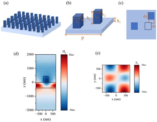
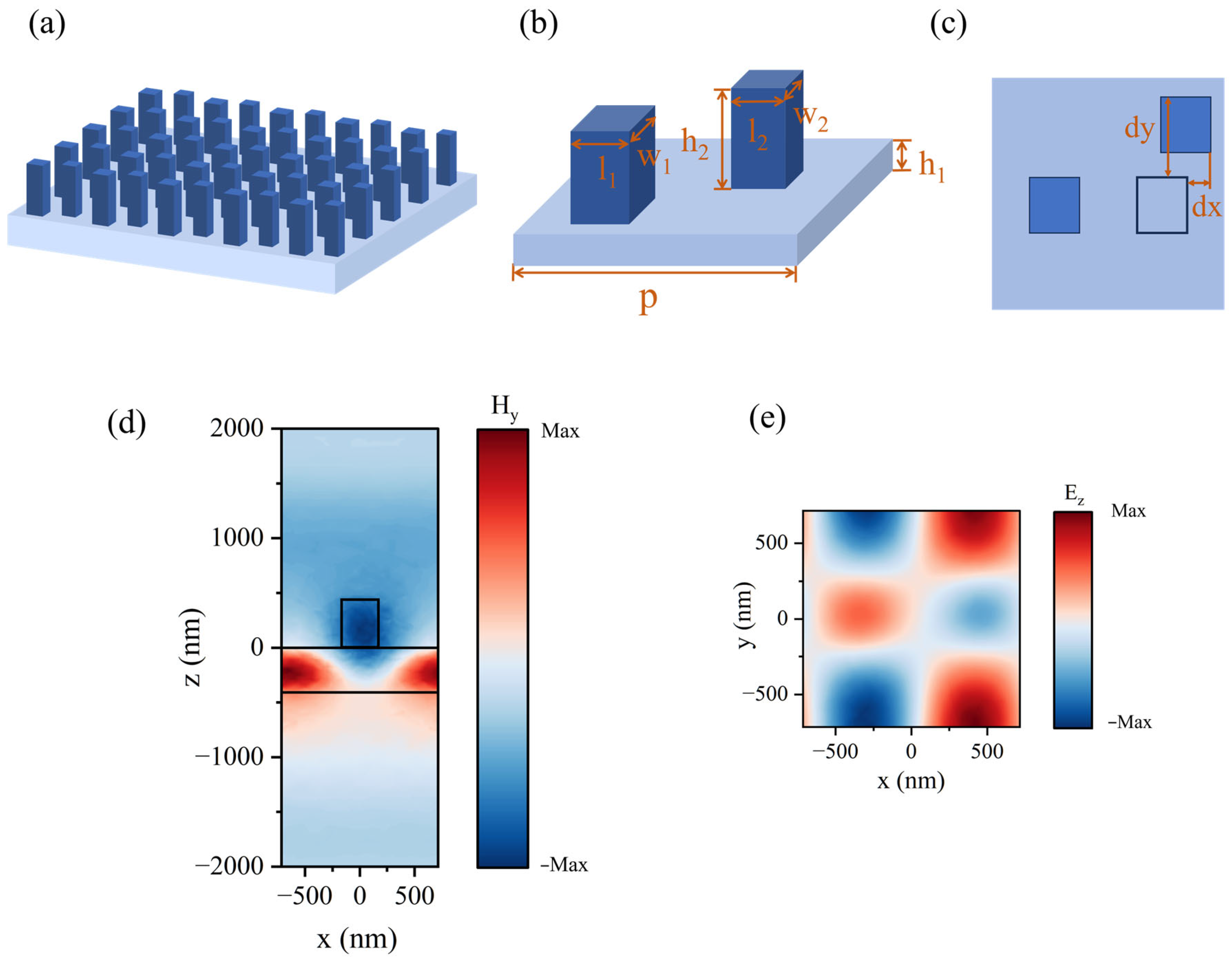
The chiral metasurface structure design is shown in Figure 1a. The structural unit consisted of a waveguide layer and two asymmetric nanocolumns. As shown in Figure 1b, the structural units are periodically arranged along the x- and y-directions with an identical square lattice, where the structural period p is 1430 nm. Each nanocolumn has a length , width , and height ; the waveguide layer has a thickness . The left column is fixed, while the right column is offset by and , as shown in Figure 1c. These displacement parameters establish the underlying chiral configuration of the structure, while the scale factor is introduced to modify the size of the right column without altering the displacement-induced asymmetry. Varying s therefore provides an additional degree of freedom for tuning the resonant properties while maintaining the chiral configuration.
Figure 1.
Metasurface structure and field maps. (a) Overall schematic. (b) Structure of a single unit cell. (c) Top view of the unit cell. (d) (y-component of magnetic field) distribution in the YZ plane of the structure. (e) (z-component of electric field) distribution at the center of the waveguide layer. Different colors are used to distinguish the substrate from the nanopillars, although both are made of Si3N4.
The optical properties of the chiral metasurface were numerically investigated using the finite-element method (FEM) with the Electromagnetic Waves, Frequency Domain interface of COMSOL Multiphysics 6.2 in 3D mode. Floquet periodic boundary conditions were applied along the x- and y-directions, and perfectly matched layers (PMLs) were introduced along the z-direction. The computational domain consisted of a single unit cell of the metasurface. The tetrahedral mesh was generated using the physics-controlled mesh settings. Both the waveguide layer and dielectric nanocolumns were composed of Si3N4 with a refractive index of 2.02. Si3N4 was selected as the dielectric material because of its low optical loss and suitable refractive index, which provide a favorable platform for high-Q dielectric resonances [42]. In addition, using the same Si3N4 material for the waveguide layer and dielectric columns avoids introducing an additional material-interface parameter, allowing the influence of the geometric modulation to be isolated.
For the baseline simulations, the extinction coefficient was set to , where absorption and material losses were neglected to isolate the intrinsic radiative characteristics of the resonances. Considering that the extinction coefficient of silicon-nitride thin films at 1550 nm can be on the order of according to experimental measurements [43], additional simulations with a weak-loss condition of were performed to evaluate the robustness of the optical response under realistic residual material absorption.
The optical response of the proposed structure originates from guided-mode resonance, a characteristic resonance mechanism in periodic waveguide gratings [44]. The dielectric waveguide layer serves as the guiding medium, whereas the periodic dielectric pillars provide the additional in-plane momentum required for coupling the incident light into the guided mode. When the incident light interacts with the periodic grating, the additional in-plane momentum provided by the grating enables the coupling of the external wave to the guided mode supported by the waveguide layer, provided that the phase-matching condition is satisfied. As a result, the incident energy is efficiently transferred into the waveguide mode, leading to strong electromagnetic field confinement within the waveguide layer. Owing to the weak coupling between the guided mode and the free-space radiation continuum, a narrow resonance linewidth is formed, giving rise to a high-Q resonance in the transmission spectrum [45,46,47].
The Q-factor is defined as , where is the resonance wavelength, and FWHM is the full width at half maximum. To further quantitatively describe the evolution of the resonant mode with the structural scaling factor s, temporal coupled-mode theory (TCMT) was employed. The temporal evolution of the resonant-mode amplitude a can be expressed as , where is the resonant angular frequency, is the total decay rate of the resonant mode, denotes the amplitudes of the incident waves, and describes the coupling between the incident waves and the resonant mode. The corresponding output-wave amplitudes can be written as , where denotes the amplitudes of the output waves, represents the direct nonresonant scattering matrix, and describes the coupling between the resonant mode and the output channels. The total decay rate can be expressed as , where and represent the radiative and nonradiative decay rates, respectively. The simulated spectra around the resonance were fitted using the TCMT response, and the total decay rate was extracted for different values of s. With material absorption neglected, the nonradiative decay rate is zero, so the extracted total decay rate corresponds directly to the radiative decay rate . This provides a quantitative description of the radiative leakage and its evolution with the geometric scaling factor s.
To verify that the observed resonance originates from guided-mode resonance, the electromagnetic field distributions at the resonance wavelength were further analyzed. As shown in Figure 1d, the magnetic field is predominantly confined within the waveguide layer rather than around the dielectric pillars, indicating that the resonant energy is mainly carried by the guided mode supported by the waveguide. Meanwhile, the Ez field distribution in the waveguide layer, shown in Figure 1e, exhibits a clear alternating positive–negative standing-wave pattern along the grating direction, which is a typical feature of guided-mode resonance. These field characteristics confirm that the incident wave is successfully coupled into the guided mode of the periodic waveguide grating and that the high-Q resonance investigated in this work originates from the guided-mode resonance mechanism.
CD is defined as , where denotes the transmittance, with the first subscript representing the outgoing polarization and the second subscript representing the incident polarization, and and denote RCP and LCP light, respectively. For planar chiral metasurfaces, breaking mirror symmetry in a single direction typically preserves some symmetric operations, precluding a strong intrinsic CD response. To achieve efficient chirality, the approach proposed in this work simultaneously introduces displacement parameters along the two orthogonal in-plane directions, breaking the in-plane mirror symmetry. Together with the out-of-plane asymmetry introduced by the substrate-supported configuration, this combined symmetry breaking enables a chiral optical response in the planar structure. From the perspective of coupled dipole models, this in-plane asymmetry induces differential coupling strengths between the polarization channels, accompanied by coherent interference between degenerate states, which gives rise to intrinsic chirality [48]. To further understand the CD response, we employ temporal coupled-mode theory (TCMT). Within the framework of polarization-dependent resonant coupling, the CD response is governed by the amplitude and phase relationships between the polarization channels. When these conditions are satisfied at the resonance wavelength, LCP and RCP exhibit distinct coupling efficiencies with the resonant mode, yielding a significant CD response [49,50]. Under normal incidence, these conditions reduce to the constraints and on the linear-polarization transmission matrix elements [49,50].
3. Results
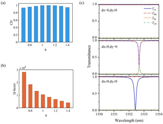
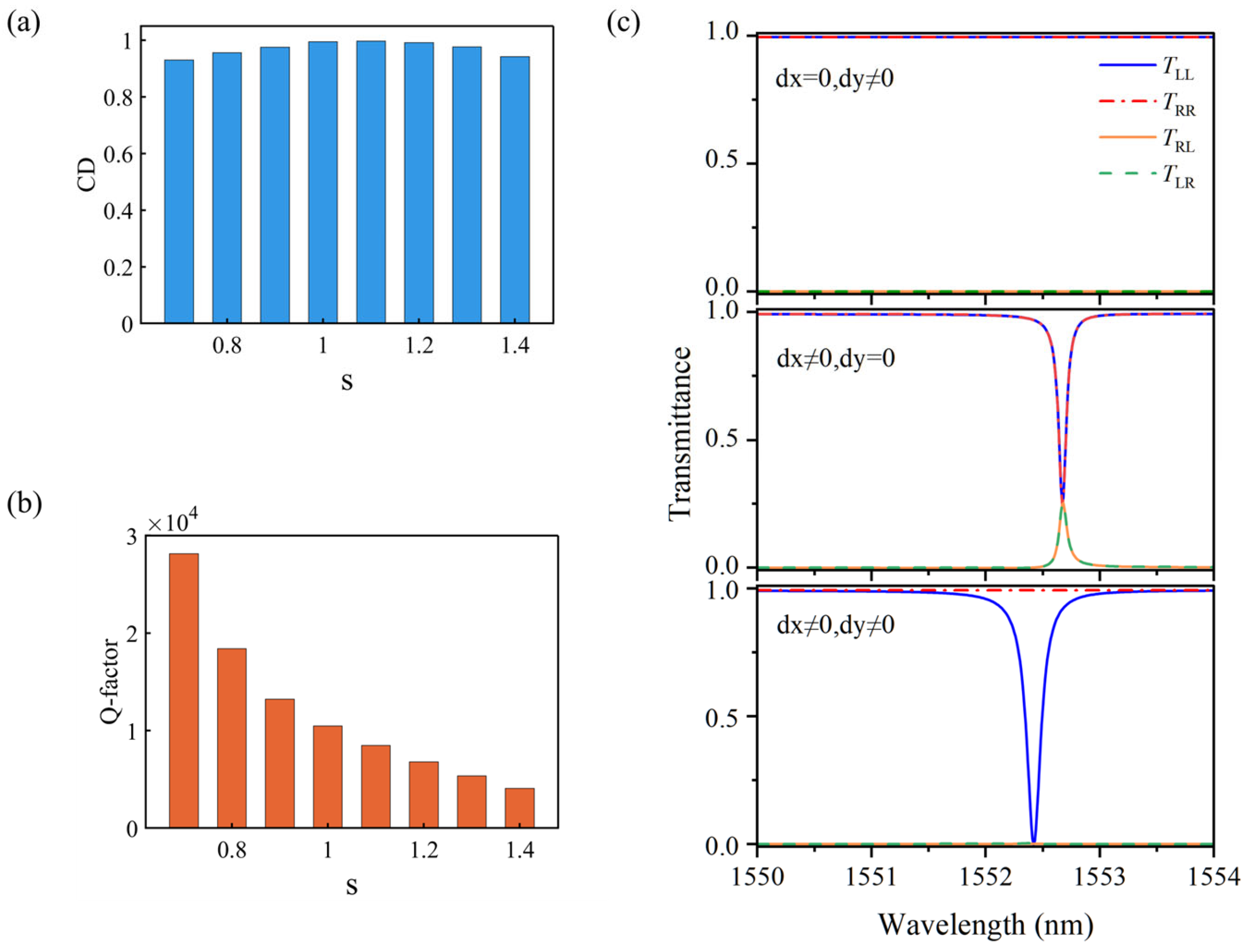
Figure 2a,b shows the optical responses of the structure for different scale factors. The results showed that, as s varied, the Q-factor could be continuously tuned over a wide range, while CD remained at a consistently high level, demonstrating that the scale factor enables effective Q-factor modulation without significantly degrading the chiral response. Specifically, the Q-factor varies from 4073 to 28,142, while the CD remains above 0.9 over the investigated tuning range.
Figure 2.
Results on chiral generation and s regulation. (a) Circular dichroism as a function of s. (b) Quality factor (Q-factor) as a function of s. (c) Transmittance curves at different offsets. In all panels, denotes transmittance for outgoing polarization and incident polarization . and denote right- and left-circular polarizations, respectively. In (c), and represent the displacements along the x and y directions.
To verify the origin of the chiral response, the transmission spectra were obtained by simulation for both single and dual direction displacements. Three asymmetric configurations were compared: (i) only an x-direction offset was introduced (), (ii) only a y-direction offset was introduced (), and (iii) both x- and y-direction offsets were introduced (). As shown in Figure 2c, with only a single direction offset, the structure retains partial symmetry, resulting in nearly identical transmission spectra for LCP and RCP incidence and consequently a negligible CD response. With both and introduced, however, the remaining in-plane mirror symmetry is further broken, leading to distinctly different transmission spectra for the two circular polarizations at the resonance wavelength and giving rise to a pronounced CD. This comparison confirms the role of the combined in-plane symmetry breaking in generating the strong chiral response.
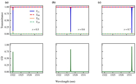
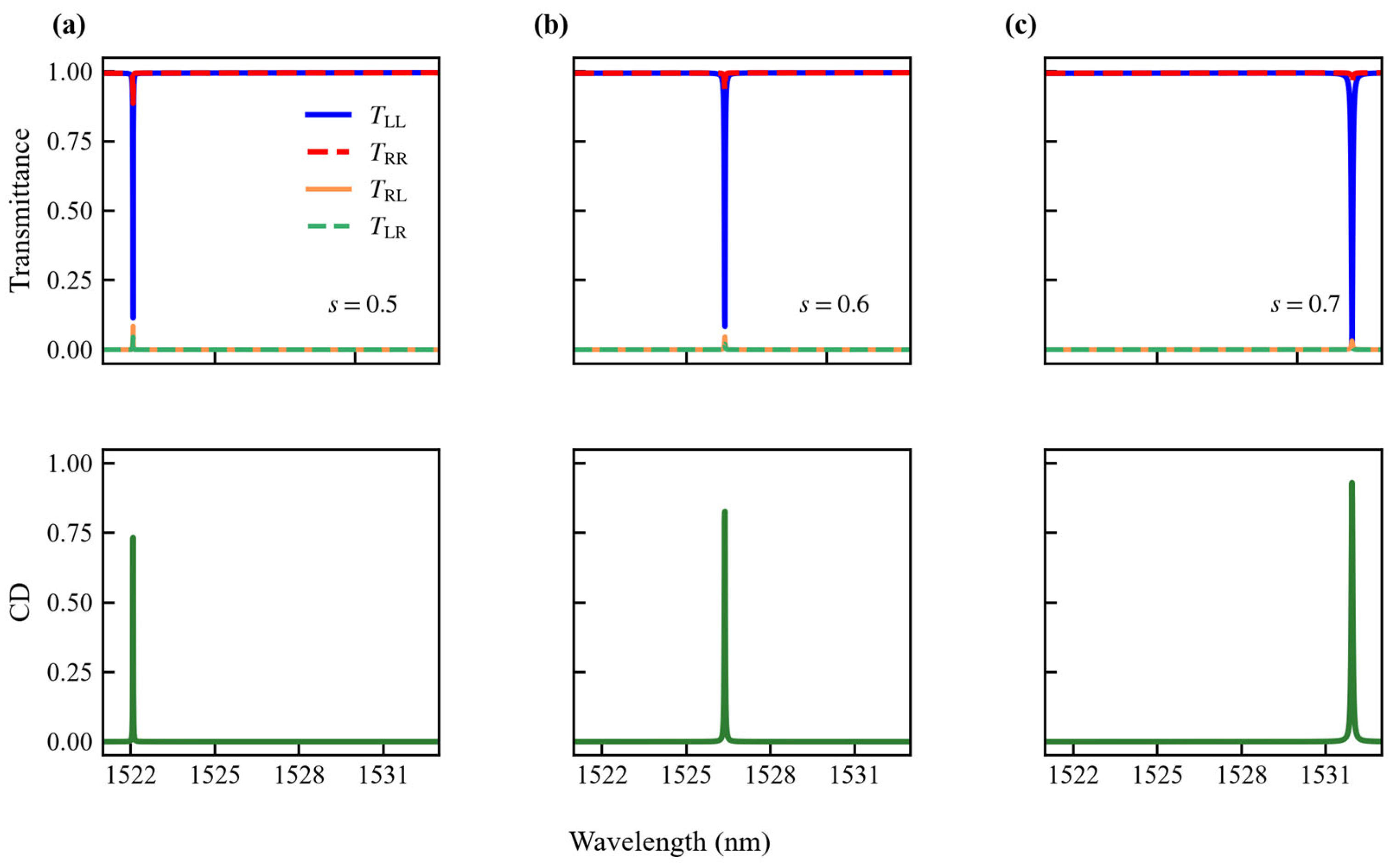
The dependence of CD on the scale factor is further examined in Figure 2b. Within the selected tuning range of , the CD remains above 0.9, indicating that a high chiral response can be maintained during Q-factor tuning. When , however, the CD gradually decreases below 0.9. Figure 3 shows the transmission spectra for representative scale factors of , 0.6, and 0.5. As s decreases from 0.7 to 0.5, the resonance positions under RCP and LCP excitation remain nearly coincident. Meanwhile, values gradually decrease, whereas the values progressively increase, while the variations in and remain relatively small. Consequently, the difference in the transmission response between the two circular polarization states gradually decreases, which is reflected in the reduced CD values. When , a further increase in the scale factor causes the lateral dimensions of the right-hand dielectric pillar to exceed the defined unit-cell boundaries, setting as the upper limit of the primary tuning range.
Figure 3.
Transmission matrix elements (top row) and CD spectra (bottom row) for (a), (b), and (c).
To further examine the stability of the CD response within the selected tuning range, the amplitude difference and the phase difference of the linear polarization transmission coefficients were extracted for s. Across the investigated range, the amplitude difference remains within , and the phase difference stays close to zero, showing only minor variation. Together with the CD data presented in Figure 2a, these results confirm that the polarization-dependent transmission characteristics remain essentially stable as s changes.
Having established the stability of the chiral response within the selected tuning range, we next investigated the mechanism underlying the Q-factor modulation. Three representative cases were selected, where the right column was smaller than the left fixed column (), equal in size to the left column (), and larger than the left fixed column (), and the electric field distributions at their respective resonance wavelengths were systematically analyzed under x-polarized excitation to investigate how the scale factor s modulated the Q-factor.
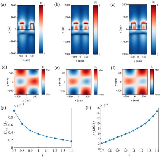
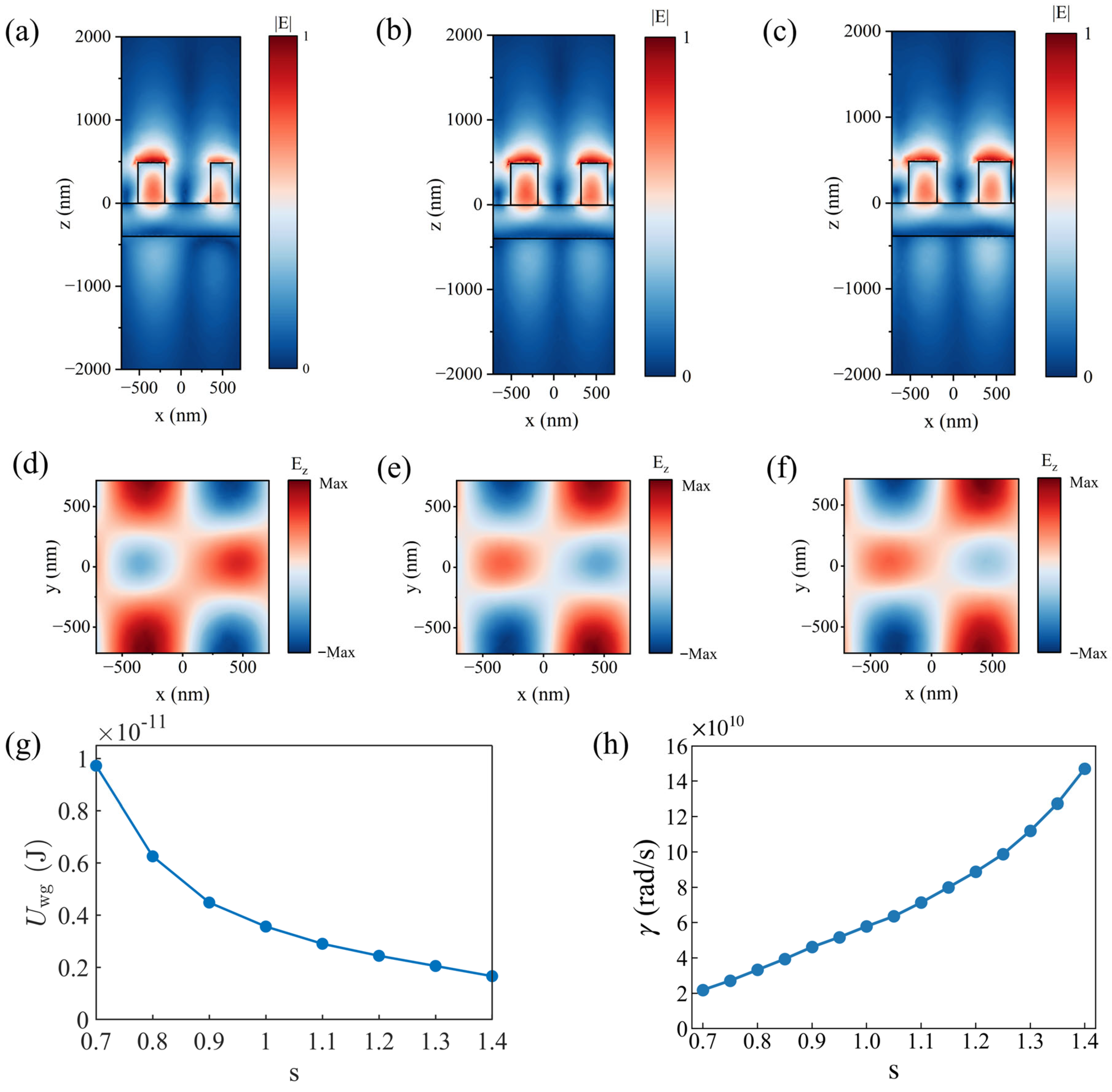
Figure 4d–f shows the Ez distributions inside the waveguide layer for the three cases. The results indicate that Ez exhibits the same spatial distribution characteristics for the different scale factors, suggesting that the overall resonant mode is maintained during the scale-factor modulation. No obvious mode switching is observed. Figure 4a–c shows the electric field mode distributions of the structure with the three different configurations. Although the overall field-distribution characteristics remain similar across different scale factors, the spatial distribution and localization of the electromagnetic field change noticeably. When , the electromagnetic field is primarily distributed between the two dielectric columns and the waveguide region beneath them, with field energy distributed relatively uniformly across both columns. As the scale factor gradually decreases, the size of the right-hand dielectric column continues to shrink, and its ability to constrain the guided mode gradually weakens. The electromagnetic field becomes increasingly concentrated near the left-hand dielectric column, which maintains a fixed size, and the difference in the electric field distributions between the two columns gradually increases. When s reaches 0.8, the electric field is primarily concentrated in the left-hand dielectric column and its corresponding waveguide region, forming a stronger localized field. At the same time, although the electric field gradually decays toward the air region for all scale factors as s increases, the electric field in the air at is significantly stronger than that at , indicating that as s increases, energy within the structure gradually leaks outward.
Figure 4.
Analysis of the causes of changes in the Q-factor with respect to the scale factor. (a) (Normalized electric field magnitude) in the structure when . (b) when ; (c) ∣E∣ when . (d) distribution inside the waveguide layer when ; (e) distribution inside the waveguide layer when . (f) distribution inside the waveguide layer when . (g) Stored energy in the waveguide layer as a function of the scale factor . (h) Decay rate as a function of the scale factor.
To further quantify the changes in the electromagnetic field distribution with the scale factor, the stored energy in the waveguide layer and the resonance decay rate were analyzed. The electromagnetic energy stored in the waveguide layer was calculated by integrating the electric- and magnetic-field energy densities over the waveguide domain under x-polarized excitation with an incident power of 1 W. Specifically, the stored energy is given by where the factor accounts for the time average of the harmonic fields Figure 4g shows the variation of the waveguide-layer stored energy with the scale factor. The stored energy decreases monotonically from J at to J at . In parallel, the resonance decay was quantified by fitting the simulated spectra around the resonance using the temporal coupled-mode theory described in Section 2. Since the present analysis focuses on the total decay rate of the resonance, , which exhibits a well-defined resonance feature, was selected as the representative transmission channel for extracting . As shown in Figure 4h, the extracted total decay rate increases monotonically from approximately rad/s at to rad/s at . These results show that the scale-factor modulation is accompanied by systematic changes in both the stored energy and decay rate of the resonance.
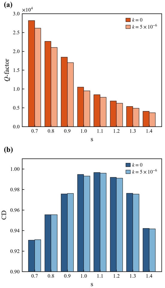
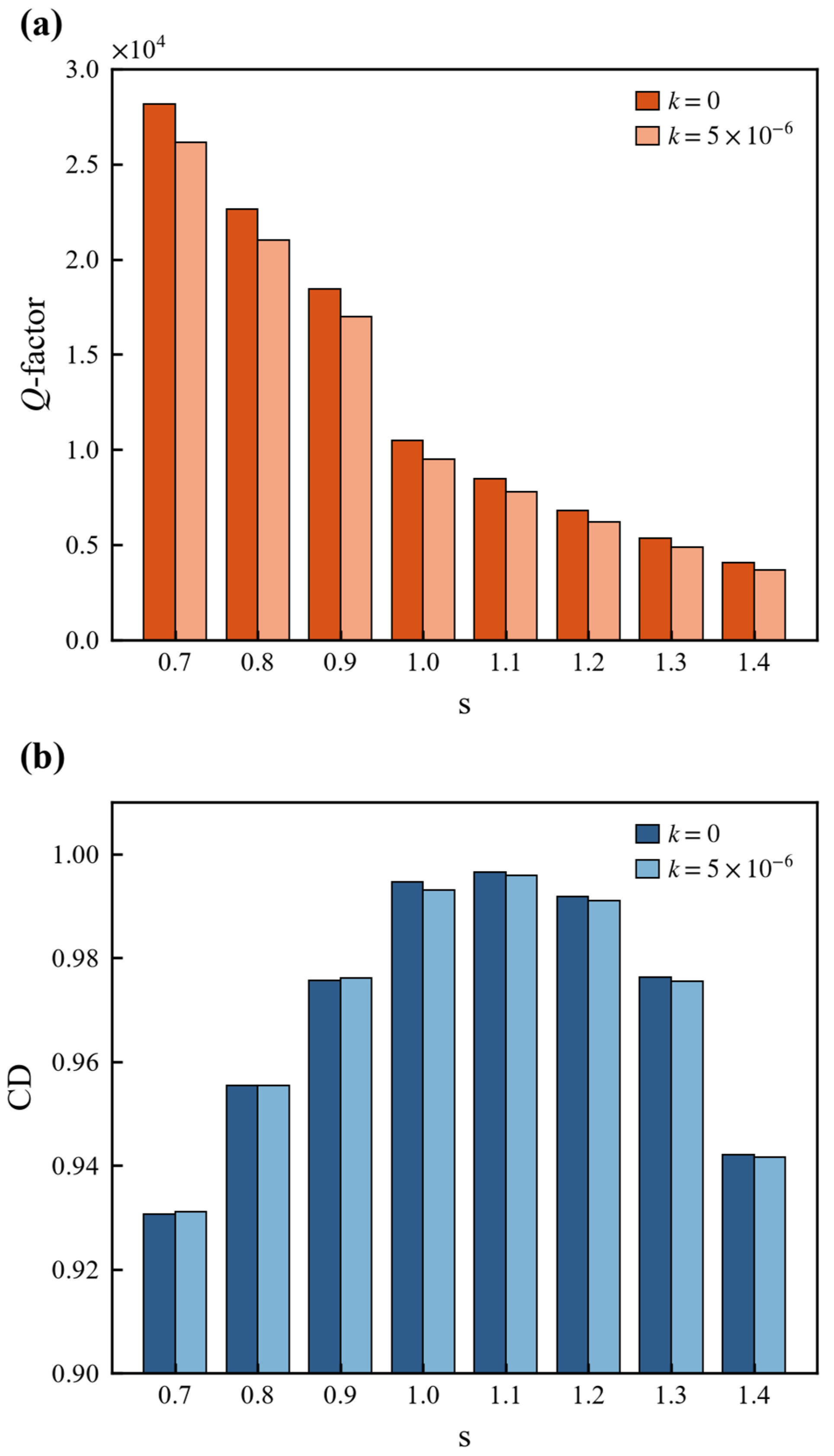
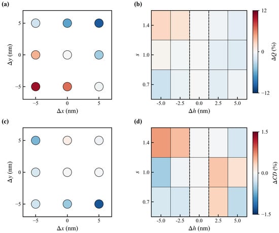
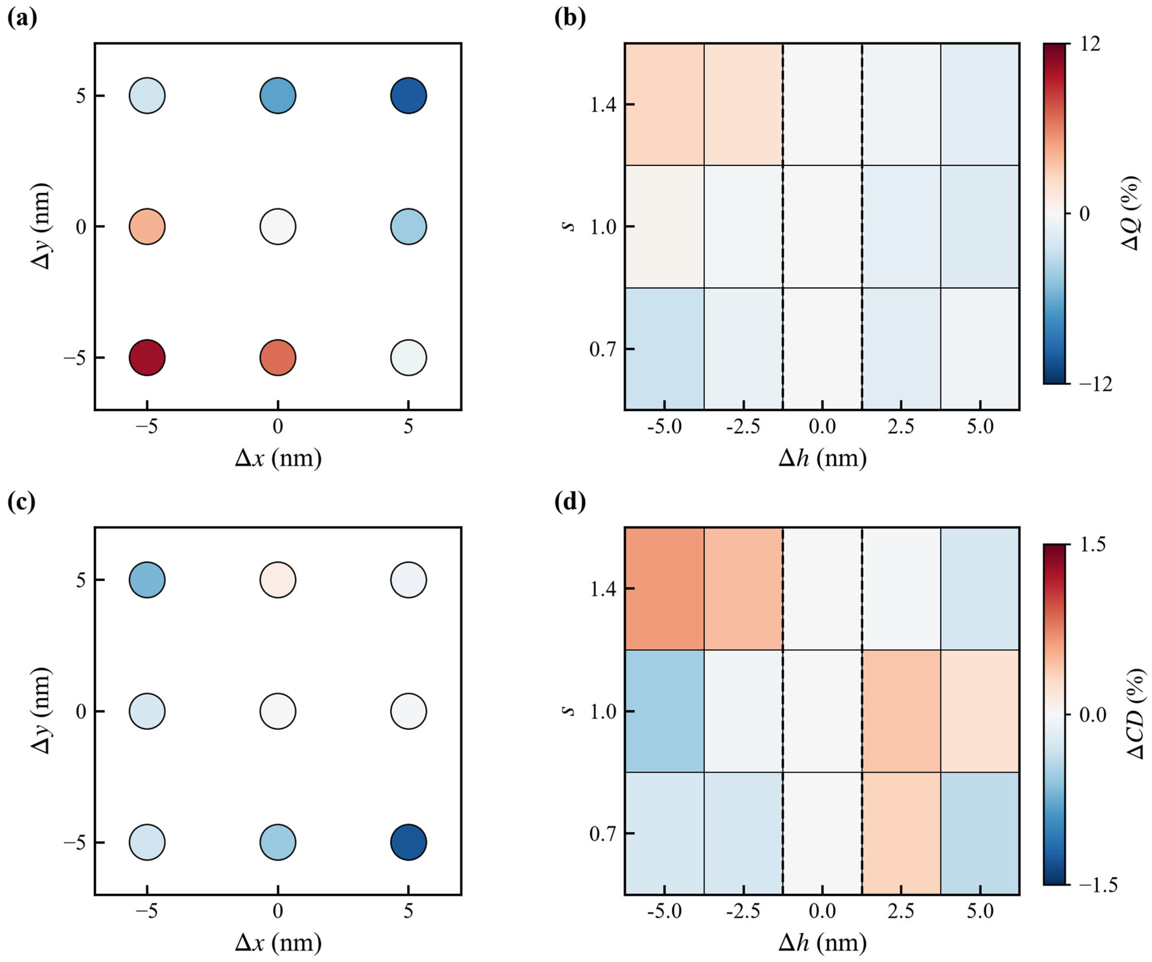
To further evaluate the robustness of the proposed structure, additional simulations were performed under the weak-loss condition of introduced in Section 2. The resulting Q-factor and CD are compared with those of the lossless case in Figure 5. The Q-factor remains continuously tunable with the scale factor s, although a moderate reduction is observed compared with the lossless case. The maximum reduction in Q-factor is approximately 7.2% at , while the difference gradually decreases as s increases. In contrast, the CD values remain nearly unchanged, with the maximum absolute variation being approximately 0.0015 over the investigated range. The effect of positional deviations of the two dielectric pillars from their nominal positions was investigated. At , positional deviations of 5 nm were introduced in the x and y directions, both individually and simultaneously. The investigated displacement combinations were (0, 0), (5, 0), (−5, 0), (0, 5), (0, −5), (5, 5), (5, −5), (−5, 5), and (−5, −5) nm. Figure 6a,c summarizes the corresponding Q-factor and CD values. The CD remains above 0.9 for all investigated cases. Relative to the nominal structure, the Q-factor varies by at most +10.26% and −10.11%, whereas the corresponding CD variation is limited to +0.11% and −1.28%. Here, the relative variation is defined as , where denotes the value for the nominal structure. In addition to the positional deviations, the influence of height deviations was further examined at , , and . The heights of the dielectric columns were varied by and relative to the nominal height. Figure 6b,d shows the corresponding Q-factor and CD values as a function of the height deviation. The CD remains above 0.9 for all investigated scale factors and height deviations, with only negligible changes relative to the nominal structures. The Q-factor also exhibits only minor variations, with the maximum relative variation being approximately 3% at each investigated scale factor. These results indicate that the high-CD response and Q-factor tuning characteristics are maintained under the considered height deviations.
Figure 5.
Q-factor (a) and CD (b) as functions of the scale factor under lossless () and weak-loss () conditions. The y-axis range in (b) is set to 0.9–1 to better visualize the variation in CD.
Figure 6.
Effects of positional and height deviations on the Q-factor and CD. (a) ΔQ (%) under positional offsets at . (b) ΔQ (%) under height deviations at , 1.0, and 1.4. (c) ΔCD (%) under positional offsets at . (d) ΔCD (%) under height deviations at , 1.0, and 1.4. The two vertical dashed lines in (b,d) mark the nominal case with . Panels (a,b) share the same color scale for , and panels (c,d) share the same color scale for .
In addition to the positional and height deviations, the effect of sidewall taper was evaluated at , and by reducing the top surface area to 0.75 times the bottom area, corresponding to an equivalent sidewall tilt of approximately 2.6°. As summarized in Table 1, the Q-factor remains continuously tunable with s under this tapered geometry (43,356 at , 15,934 at , and 11,151 at , while the resonance blue-shifts by 15–18 nm. In contrast, the CD decreases markedly, from 0.931 to 0.664 at , from 0.995 to 0.856 at , and from 0.992 to 0.927 at . T Notably, the CD reduction is more pronounced at smaller s, where the Q-factor is higher, while at the CD remains above 0.9.
Table 1.
Effect of sidewall taper on the Q-factor and CD at , 1 and 1.2.
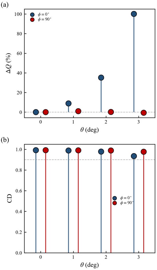
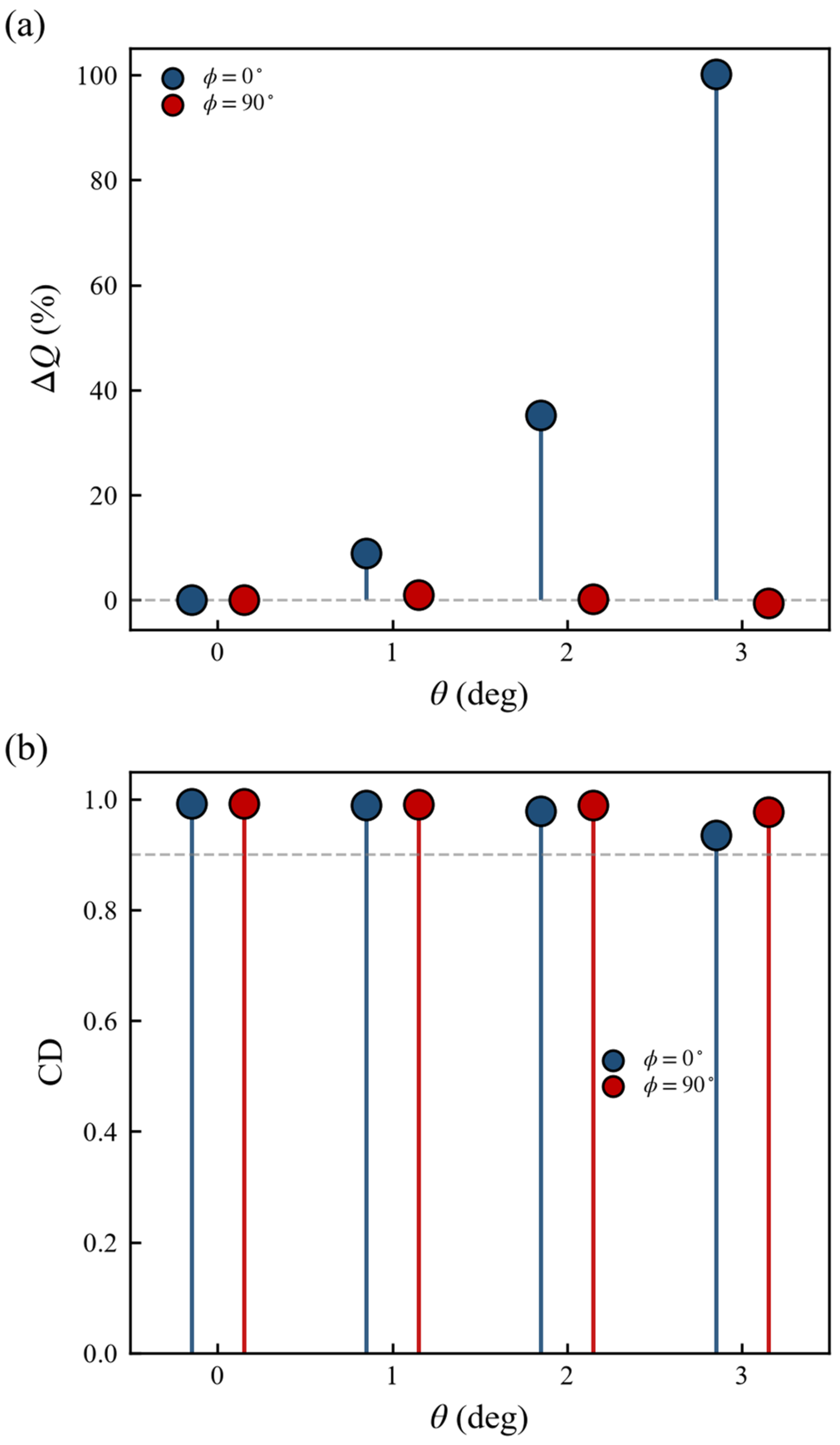
Finally, the sensitivity of the optical response to small deviations in the incident angle was evaluated. At , simulations were performed for incident angles of 0–3° at two representative azimuthal angles, and . Figure 7 shows the corresponding variations in the Q-factor and CD with the incident angle. For , both the Q-factor and CD exhibit only minor changes, with maximum variations of 1.02% and 1.54%, respectively. In contrast, for, the Q-factor exhibits a maximum variation of 100.13%, whereas the maximum CD variation is 5.78%. Here, the relative variation is defined as , where denotes the value at normal incidence. Despite the different angular sensitivities of the Q-factor, the CD remains above 0.9 for all investigated incident angles and both azimuthal directions.
Figure 7.
Angular dependence of the Q-factor and CD. (a) Relative variation of the Q-factor, (%), as a function of the incident angle for azimuth angles (circles) and (squares) at . (b) CD as a function of the incident angle for (circles) and (squares) at . The gray dashed line in (a) marks , and the gray dashed line in (b) marks . The small horizontal offsets between the two sets of markers are used only for visual clarity.
4. Discussion
The results of this study indicate that by varying the scaling factor s, the Q-factor can be effectively adjusted within the selected range of while maintaining a high and relatively stable CD value, as shown in Figure 2a,b. In this method, the relative positions of the two dielectric pillars remain unchanged, while the length and width of the right-hand pillar are scaled simultaneously by the same multiple. The variation in the stored energy within the waveguide layer and the total decay rate indicate that the scale-factor modulation systematically modifies the energy-storage and decay characteristics of the resonance, providing a physical basis for continuous Q-factor tuning without significantly disrupting the polarization-selective response established by the original asymmetric structure. Beyond the structural design, the choice of dielectric material also contributes to the suitability of the proposed platform for high-Q resonance applications. The selected Si3N4 combines low optical loss with a suitable refractive index, providing a suitable dielectric platform for supporting high-Q resonances while minimizing the effects of material absorption. Other high-refractive-index dielectric materials, such as Si, GaP, TiO2 and GaN, may also be used for similar applications; their suitability depends on factors such as the operating wavelength, optical loss, refractive index and fabrication requirements. Furthermore, the use of rectangular dielectric pillars provides a simple and well-defined geometric structure, in which both length and width can be controlled simultaneously via a single scaling factor. This facilitates systematic adjustment of the Q-factor while preserving the underlying symmetry-breaking structure. These characteristics provide a relatively simple structural platform for achieving Q-factor tuning while maintaining a high chiral response.
However, the nearly independent modulation of the Q-factor and CD is maintained within a finite range of the scale factor. When , however, the Q-factor continues to increase, whereas the CD gradually decreases from 0.93 at to 0.89 at and 0.69 at , respectively. This decrease in CD is accompanied by a progressive reduction in the transmission contrast between the two circular polarization states, while their resonance positions remain nearly coincident. These results indicate that the reduction in CD primarily arises from weakened polarization selectivity rather than a substantial shift or splitting of the resonance.
In order to investigate further the phenomenon of reduced polarization selectivity as s decreases, the stored energy in the waveguide layer was evaluated for both RCP and LCP incident light at , and (using the same integration over the waveguide domain as in Figure 4g. Although the stored energy increases with decreasing s for both LCP and RCP excitation, the ratio decreases from approximately 79 at to 41 at , and further to 22 at . The reduced contrast in stored energy between the two circularly polarized states is consistent with the decreased polarization selectivity observed in the transmission spectra. Meanwhile, Figure 4a–f shows that the resonant field distributions exhibit similar spatial characteristics over the main tuning range, with no obvious change in the resonant mode. Taken together, these results suggest that the degradation of CD for is more likely associated with a weakening of polarization-selective coupling within the resonant mode, rather than an apparent change in the mode itself. Thus, within the selected range of , the Q-factor and CD can be tuned with minimal change in CD; however, this decoupling has a finite range, and further reduction of the scale factor is accompanied by a gradual loss of polarization selectivity. It is also worth noting that, for the lossless structure considered here, the total decay rate extracted from the TCMT fitting is equivalent to the radiative decay rate since non-radiative material loss is neglected. Accordingly, the Q-factor is inversely related to the radiative decay rate. As s increases from 0.7 to 1.4, the Q-factor decreases continuously from 28,142 to 4073, accompanied by an increase in the extracted radiative decay rate. No divergent-Q limit or complete suppression of radiative coupling is observed within this range. As shown in Figure 4g, the decrease in Q-factor with increasing s is accompanied by a reduction in the waveguide-layer stored energy and an increase in the total decay rate. In the present lossless model, radiative leakage is the intrinsic mechanism governing the Q-factor, while the changes in stored energy and field localization reflect the resulting modification of the radiative decay. This finite and continuously varying behavior indicates that the resonance remains radiatively coupled rather than approaching an ideal bound state in the continuum. Therefore, the resonance is interpreted within the GMR framework rather than as a chiral bound states in the continuum (BIC).
As shown in Figure 5a, when a nonzero extinction coefficient is introduced, the reduction in Q is more pronounced at smaller s values. For the present structure, the higher-Q resonances are associated with stronger electromagnetic energy storage and field localization within the dielectric structure. The field distributions obtained from the lossless model show that the electromagnetic energy is mainly concentrated in the waveguide layer and nanocolumns at smaller s, indicating stronger overlap with the dielectric material. Consequently, when material absorption is introduced, the additional non-radiative loss has a more pronounced effect on the Q-factor. As s increases and the Q-factor decreases, the field becomes less concentrated within the dielectric region, reducing the influence of material absorption. This explains why the difference between the lossless and lossy Q-factor curves gradually decreases with increasing s. In contrast, the CD remains nearly unchanged over the investigated tuning range. Since the CD is governed by the difference between the LCP and RCP responses, the small material loss mainly adds a non-radiative decay channel without significantly changing the relative difference between the two circularly polarized responses. Thus, the Q-factor remains tunable while a high CD is maintained even when a small material loss is considered, although the maximum achievable Q-factor is ultimately limited by material absorption.
The robustness analysis provides further insight into the practical tolerance of the Q-factor and CD modulation. The positional-misalignment results in Figure 6a,c show that the CD is considerably less sensitive to the considered structural perturbations than the Q-factor, with the CD variation remaining within 1.28% for positional deviations of up to 5 nm. The relatively larger variation in Q-factor, with a maximum deviation of approximately 10%, is likely associated with changes in the radiation loss of the resonant mode induced by the relative positional variations of the two dielectric columns. Nevertheless, the high-CD response is preserved throughout the investigated positional deviations. The height-deviation results in Figure 6b,d further show that the optical response is even less sensitive to moderate variations in the column height. For height deviations of up to ±5 nm, the CD remains above 0.9, while the Q-factor changes by only approximately 3% at the investigated scale factors. This indicates that the scale-factor-dependent Q modulation and high-CD response are not strongly dependent on the nominal column height.
In addition to the positional and height deviations, the effect of sidewall taper was evaluated at , 1, and 1.2 using a representative top-to-bottom area ratio of 0.75 (equivalent tilt angle ~2.6°). The Q-factor remains continuously tunable under the tapered geometry (43,356 at , 15,934 at , and 11,151 at ), while the resonance blue-shifts by 15–18 nm. In contrast, the CD decreases markedly, from 0.931 to 0.664 at , from 0.995 to 0.856 at and from 0.992 to 0.927 at . Notably, at the CD remains above 0.9, while at smaller s (higher Q) the CD reduction becomes more pronounced. This indicates that the Q-tuning mechanism is robust against sidewall taper, whereas the CD is more sensitive to this structural imperfection. The stronger CD reduction at smaller s is consistent with the higher field confinement at higher Q-factors, which enhances the overlap between the resonant mode and the tapered sidewall. These results suggest that while the Q-factor tuning is tolerant of moderate sidewall taper, tighter fabrication control may be required to preserve a high CD in practical devices.
Beyond material and structural perturbations, deviations in the incident direction also affect the optical response. The angular-dependence results indicate that the Q-factor and CD exhibit different sensitivities to the incident direction. In particular, the Q-factor shows a pronounced dependence on the incident angle for , whereas the CD remains above 0.9 throughout the investigated 0–3° angular range for both azimuthal directions. This indicates that the high-CD response is less sensitive to small incident-angle deviations than the Q-factor. Therefore, although the proposed structure retains a high chiral response under the considered small incident-angle deviations, accurate control of the incident direction is more important when operating at high Q-factors. Taken together, these results indicate that the key optical characteristics of the proposed structure are maintained under the considered material and structural perturbations and small incident-angle deviations, supporting its robustness against moderate fabrication and operational deviations.
To position the present work within recent developments in the independent or weakly coupled control of the Q-factor and CD, several representative studies are summarized in Table 2. These works employ different structural degrees of freedom to regulate the radiative loss and spin-dependent coupling of chiral resonances. In contrast to Zhang et al. [40], who tuned the Q-factor by varying and at a fixed ratio , the present work keeps the positional asymmetry fixed and tunes the Q-factor through a single dimensional scaling factor s applied to one dielectric column. In the present work, the length and width of the right-hand dielectric column are simultaneously scaled by a single scale factor s, while the positional asymmetry of the two dielectric columns is kept fixed. Within the primary tuning range of , this dimensional scaling enables continuous tuning of the Q-factor from 4073 to 28,142 while maintaining CD above 0.9. The lower bound of the tuning range is determined by the degradation of CD for , whereas the upper bound is constrained by the unit-cell boundary. Thus, the proposed design provides a route for continuously tuning the Q-factor through dimensional scaling without directly modifying the positional asymmetry responsible for the chiral response.
Table 2.
Comparison of Q-factor and CD control strategies.
It should be noted that the Q-factors reported in Table 2 should not be regarded as a direct performance ranking because the compared studies employ different resonance types, material systems, loss conditions, and validation methods. In particular, the Q-factors reported by Li et al. [39] and Sun et al. [41] are experimentally measured values, whereas the Q-factor range in the present work is obtained from a lossless dielectric model. The experimental Q-factors are further influenced by non-ideal loss channels such as material absorption, fabrication imperfections, and scattering, rather than being solely determined by the intrinsic radiative loss of the designed resonance. The comparison is therefore intended to highlight differences in the mechanisms and structural degrees of freedom used for Q–CD control rather than to establish a universal Q-factor ranking.
Finally, in contrast to Zhang et al. [40], Li et al. [39], An et al. [38], and Sun et al. [41], which all rely on two or more structural parameters for independent Q–CD control, the present work focuses on Q-factor modulation while preserving a high and relatively stable CD response. The main distinction of the present approach therefore lies in using dimensional scaling as a Q-tuning degree of freedom while retaining the chiral-generating positional asymmetry. The cross-sectional shape of the dielectric columns can also influence the modal field distribution and radiative coupling and thus affect the Q-factor. In the present work, rectangular columns are adopted to provide a simple and well-defined geometry for dimensional scaling, and a systematic comparison of alternative column shapes was therefore not performed. Compared with the multi-parameter approaches summarized in Table 2, the present work achieves Q-factor tuning with a single parameter while the CD remains naturally stable, avoiding the need for an additional parameter to control or compensate the CD. This simplifies the tuning procedure and offers a more practical route for planar chiral metasurfaces. Reciprocal dynamic tuning of CD at a fixed Q-factor was not addressed in this study and could be explored in future work.
5. Conclusions
This study presents a chiral metasurface based on dual-dielectric columns and guided-mode resonance. Mirror symmetry is broken by introducing positional offsets along two orthogonal directions, resulting in a strong chiral response. A scale factor is then introduced to modify the dimensions of one dielectric column while keeping the relative positional asymmetry fixed. By varying the scale factor s, the electromagnetic field distribution and energy storage within the dielectric columns and waveguide layer are modified, thereby enabling continuous modulation of the Q-factor.
The results show that the Q-factor can be continuously tuned from 4073 to 28,142, while the CD remains above 0.9 over the primary tuning range , with a relative standard deviation of 2.6%. The lower bound of this range is determined by the decrease in CD for , whereas further increasing s causes the right-hand dielectric column to exceed the unit-cell period. The decrease in CD at is not fully understood and requires further investigation. In addition, the Q-factor remains tunable under weak material loss, although material absorption limits the maximum achievable Q-factor. The structural-robustness analysis further shows that the high-CD response is maintained under the considered positional and height deviations, while the Q-factor exhibits moderate variations.
Taken together, these results establish a single-scale-factor approach for continuously tuning the Q-factor while maintaining a strong and stable chiral response. Further investigation of the mechanism responsible for the CD reduction at small s, as well as the development of strategies for dynamically tuning CD while maintaining a nearly constant Q-factor, may provide additional degrees of freedom for chiral metasurface design. The proposed approach provides a design route for high-Q chiral metasurfaces with potential applications in polarization control, chiral sensing, and enhanced light–matter interactions.
Author Contributions
Conceptualization, F.C.; methodology, F.C. validation, F.C. and S.Z.; formal analysis, S.Z.; investigation, S.Z.; resources, S.Z.; data curation, S.Z.; writing—original draft prep-aration, S.Z.; writing—review and editing, F.C.; visualization, S.Z.; supervision, F.C.; project ad-ministration, F.C. All authors have read and agreed to the published version of the manuscript.
Funding
This research received no external funding.
Institutional Review Board Statement
Not applicable.
Informed Consent Statement
Not applicable.
Data Availability Statement
All data generated or analyzed during this study are contained within the article. The simulation results are reproducible based on the methods and parameters described herein.
Acknowledgments
The authors would like to thank Chongjun He for valuable discussions on several key physical insights. Thanks are given to Jiahao Zha for assistance in simulation setup.
Conflicts of Interest
The authors declare no conflicts of interest.
Abbreviations
The following abbreviations are used in this manuscript:
| CD | Circular dichroism |
| GMR | Guided-mode resonance |
| LCP | Left circularly polarized |
| RCP | Right circularly polarized |
| TCMT | Temporal coupled mode theory |
| BIC | Bound states in the continuum |
| QGM | Quasi-guided mode |
References
- Niu, X.; Zhao, R.; Yan, S.; Pang, Z.; Li, H.; Yang, X.; Wang, K. Chiral Materials: Progress, Applications, and Prospects. Small 2023, 19, 2303059. [Google Scholar] [CrossRef] [Scilit]
- Meskers, S.C.J. Consequences of Chirality on the Response of Materials. Mater. Adv. 2022, 3, 2324–2336. [Google Scholar] [CrossRef] [Scilit]
- Bousquet, E.; Fava, M.; Romestan, Z.; Gómez-Ortiz, F.; McCabe, E.E.; Romero, A.H. Structural Chirality and Related Properties in Periodic Inorganic Solids: Review and Perspectives. J. Phys. Condens. Matter 2025, 37, 163004. [Google Scholar] [CrossRef] [Scilit]
- Chen, Y.; Gao, J.; Yang, X. Chiral Metamaterials of Plasmonic Slanted Nanoapertures with Symmetry Breaking. Nano Lett. 2018, 18, 520–527. [Google Scholar] [CrossRef] [Scilit]
- Cheeseman, L.; Forbes, K.A. Nonlinear Vortex Dichroism in Chiral Molecules. Adv. Opt. Mater. 2025, 13, 2402151. [Google Scholar] [CrossRef] [Scilit]
- Sha, X.; Du, K.; Zeng, Y.; Lai, F.; Yin, J.; Zhang, H.; Song, B.; Han, J.; Xiao, S.; Kivshar, Y.; et al. Chirality Tuning and Reversing with Resonant Phase-Change Metasurfaces. Sci. Adv. 2024, 10, eadn9017. [Google Scholar] [CrossRef] [Scilit]
- Hu, H.; Zhou, C.; Zhang, Y.; Hu, M.-X.; Peng, J.; Tang, H.; Huang, L.; Liu, J.; Guan, C.; Zhu, Z.; et al. Robust Chirality via Merging Accidental BICs with Net Zero Topological Charge. eLight 2026, 6, 12. [Google Scholar] [CrossRef] [Scilit]
- Deng, Q.-M.; Li, X.; Hu, M.-X.; Li, F.-J.; Li, X.; Deng, Z.-L. Advances on Broadband and Resonant Chiral Metasurfaces. npj Nanophotonics 2024, 1, 20. [Google Scholar] [CrossRef] [Scilit]
- Wan, X.; Li, Y.; Wang, Y.; Li, Y.; Zhang, C. Recent Advances in Chiral and Achiral Metasurfaces Under Symmetry Preservation and Breaking. Symmetry 2025, 17, 1001. [Google Scholar] [CrossRef] [Scilit]
- Gorkunov, M.V.; Antonov, A.A.; Mamonova, A.V.; Muljarov, E.A.; Kivshar, Y. Substrate-Induced Maximum Optical Chirality of Planar Dielectric Structures. Adv. Opt. Mater. 2025, 13, 2402133. [Google Scholar] [CrossRef] [Scilit]
- Chen, Y.; Deng, H.; Sha, X.; Chen, W.; Wang, R.; Chen, Y.-H.; Wu, D.; Chu, J.; Kivshar, Y.S.; Xiao, S.; et al. Observation of Intrinsic Chiral Bound States in the Continuum. Nature 2023, 613, 474–478. [Google Scholar] [CrossRef] [Scilit]
- Shi, T.; Deng, Z.-L.; Geng, G.; Zeng, X.; Zeng, Y.; Hu, G.; Overvig, A.; Li, J.; Qiu, C.-W.; Alù, A.; et al. Planar Chiral Metasurfaces with Maximal and Tunable Chiroptical Response Driven by Bound States in the Continuum. Nat. Commun. 2022, 13, 4111. [Google Scholar] [CrossRef] [Scilit]
- Lv, S.; Wei, H.; Luo, W.; Zhai, B.; Su, Z. Giant Circular Dichroism and Ultra-High Q-Factor Resonance Induced by qBIC Excitation in Oblique Lattice Metasurfaces. Results Phys. 2026, 87, 108700. [Google Scholar] [CrossRef] [Scilit]
- Cheng, J.; Li, Z.; Choi, D.-Y.; Liu, W.; Zhang, Y.; Yu, S.; Cheng, H.; Tian, J.; Chen, S. Counterintuitive Reversal of Circular Dichroism via Controllable Plasmonic Guided Mode Resonance in Diatomic Metasurfaces. Laser Photonics Rev. 2025, 19, 2401184. [Google Scholar] [CrossRef] [Scilit]
- Zhang, Y.; Liu, X.; Zhao, R.; Li, J. High Q-Factor Chiroptical Response Based on Unidirectional Guided Resonances. Opt. Lett. 2025, 50, 6349–6352. [Google Scholar] [CrossRef] [Scilit]
- Luo, X.; Du, X.; Huang, R.; Li, G. High- Q and Strong Chiroptical Responses in Planar Metasurfaces Empowered by Mie Surface Lattice Resonances. Laser Photonics Rev. 2023, 17, 2300186. [Google Scholar] [CrossRef] [Scilit]
- Hu, J.; Xiao, Y.; Zhou, L.-M.; Jiang, X.; Qiu, W.; Fei, W.; Chen, Y.; Zhan, Q. Ultra-Narrow-Band Circular Dichroism by Surface Lattice Resonances in an Asymmetric Dimer-on-Mirror Metasurface. Opt. Express 2022, 30, 16020–16030. [Google Scholar] [CrossRef] [Scilit]
- Wu, J.; Jiang, H.; Guo, Z.; Sun, Y.; Li, Y.; Chen, H. Giant Optical Chirality in Dielectric Metasurfaces Induced by Toroidal Dipole Resonances. Opt. Lett. 2023, 48, 916–919. [Google Scholar] [CrossRef] [Scilit]
- Ma, T.; Tian, J.; Sang, W.; Wang, D.; Li, J. High Q Chiroptical Responses Driven by Toroidal Dipole Resonance in All-Dielectric Metasurfaces. IEEE Photonics Technol. Lett. 2023, 35, 963–966. [Google Scholar] [CrossRef] [Scilit]
- Zhao, Y.; Askarpour, A.N.; Sun, L.; Shi, J.; Li, X.; Alù, A. Chirality Detection of Enantiomers Using Twisted Optical Metamaterials. Nat. Commun. 2017, 8, 14180. [Google Scholar] [CrossRef] [Scilit]
- Solomon, M.L.; Saleh, A.A.E.; Poulikakos, L.V.; Abendroth, J.M.; Tadesse, L.F.; Dionne, J.A. Nanophotonic Platforms for Chiral Sensing and Separation. Acc. Chem. Res. 2020, 53, 588–598. [Google Scholar] [CrossRef] [Scilit]
- Zou, Y.; Wang, D.; Afzal, I.; Kong, D.; Wang, R.; Ma, T. Terahertz Biochemical Sensing for Enantiomers Based on All-Dielectric Chiral Metasurface. Opt. Lasers Eng. 2026, 196, 109456. [Google Scholar] [CrossRef] [Scilit]
- Basiri, A.; Chen, X.; Bai, J.; Amrollahi, P.; Carpenter, J.; Holman, Z.; Wang, C.; Yao, Y. Nature-Inspired Chiral Metasurfaces for Circular Polarization Detection and Full-Stokes Polarimetric Measurements. Light Sci. Appl. 2019, 8, 78. [Google Scholar] [CrossRef] [Scilit]
- Xiao, G.; Pei, L.; Li, K.; Li, H.; Yue, H.; Yang, H. Design of Chiral Metasurfaces for Dynamic Tunable Holographic Imaging in Dirac Semimetals. Appl. Opt. 2025, 64, 9754–9759. [Google Scholar] [CrossRef] [Scilit]
- Zheng, X.; Ji, R.; Ren, L.; Wu, X.; Li, Z.; Song, K.; Yu, P.; Li, X.; Liu, F.; Xie, X. Chiral Metasurfaces with Decoupled Intensity-Phase Control for Multifunctional Optical Security and Holographic Displays. Adv. Opt. Mater. 2025, 13, 2500628. [Google Scholar] [CrossRef] [Scilit]
- Song, X.; Liu, X.; Ji, T.; Li, C.; Zhang, R.; Zhang, H.; Liu, L.; Zhang, J.; Dai, Z.; Ye, Y.; et al. Chiral Terahertz Multifunctional Metasurface Based on Dirac Semimetal for Wavefront Manipulation. Opt. Commun. 2025, 591, 132120. [Google Scholar] [CrossRef] [Scilit]
- Gou, Y.; Zheng, S.; Qing, Y.M.; Wang, Z.X.; Wu, L.W.; Liu, L.L.; Ma, H.F. Low-Absorption Dual-Chirality Metasurfaces for Polarization-Frequency Multiplexed Wavefront Manipulation. Chem. Phys. Lett. 2026, 885, 142612. [Google Scholar] [CrossRef] [Scilit]
- Sun, Z.; Li, Y.; Yin, S.; Mao, Y.; Zhou, Y.; Tang, Z. Design and Applications of a Metasurface Supporting Chiral Quasi-Bound State in the Continuum: Refractive Index Sensing and Nonlinear Harmonic Generation. Photonics Nanostruct.-Fundam. Appl. 2025, 65, 101402. [Google Scholar] [CrossRef] [Scilit]
- Hou, G.; Ju, Y.; Qiu, Z.; Wang, W. Chiral Quasi-Bound States in the Continuum for Third Harmonic Generation with Giant Chirality. Eur. Phys. J. D. 2026, 80, 39. [Google Scholar] [CrossRef] [Scilit]
- Yuan, H.; Lu, C.; Li, P.; Geng, J.; Shi, L. Chiral Nanoscale Metasurfaces Enabled by Quasi-Bound States in Continuum for Nonlinear Circular Dichroism and Biosensing. ACS Appl. Nano Mater. 2026, 9, 3512–3522. [Google Scholar] [CrossRef] [Scilit]
- Warning, L.A.; Miandashti, A.R.; McCarthy, L.A.; Zhang, Q.; Landes, C.F.; Link, S. Nanophotonic Approaches for Chirality Sensing. ACS Nano 2021, 15, 15538–15566. [Google Scholar] [CrossRef] [Scilit]
- Zhang, Y.; Song, Q.; Hou, B.; Yi, Z. Steerable Intrinsic Chirality Mediated by Toroidal Dipole Bound States in the Continuum in an Active Metasurface. Opt. Lett. 2025, 50, 2868–2871. [Google Scholar] [CrossRef] [Scilit]
- Lv, S.; Wei, H.; Luo, W.; Zhai, B.; Su, Z. Exciting Quasi-BICs for Chirality in Symmetry-Broken Monoclinic Metasurfaces. Opt. Commun. 2026, 601, 132715. [Google Scholar] [CrossRef] [Scilit]
- Gromyko, D.; An, S.; Gorelik, S.; Xu, J.; Lim, L.J.; Lee, H.Y.L.; Tjiptoharsono, F.; Tan, Z.-K.; Qiu, C.-W.; Dong, Z.; et al. Unidirectional Chiral Emission via Twisted Bi-Layer Metasurfaces. Nat. Commun. 2024, 15, 9804. [Google Scholar] [CrossRef] [Scilit]
- Zhang, X.; Liu, Y.; Han, J.; Kivshar, Y.; Song, Q. Chiral Emission from Resonant Metasurfaces. Science 2022, 377, 1215–1218. [Google Scholar] [CrossRef] [Scilit]
- An, M.; Lin, L.; Wang, K.; Ding, Q.; Zhang, Y.; Wang, W.; Zheng, X. Independent Control of Quality Factor and Circular Dichroism via Intrinsic Chiral Plasmonic Bound States in the Continuum. Laser Photonics Rev. 2026, 20, e01707. [Google Scholar] [CrossRef] [Scilit]
- Lio, G.E.; Ferraro, A.; Kowerdziej, R.; Govorov, A.O.; Wang, Z.; Caputo, R. Engineering Fano-Resonant Hybrid Metastructures with Ultra-High Sensing Performances. Adv. Opt. Mater. 2023, 11, 2203123. [Google Scholar] [CrossRef] [Scilit]
- Joseph, S.; Sarkar, S.; Joseph, J. Grating-Coupled Surface Plasmon-Polariton Sensing at a Flat Metal–Analyte Interface in a Hybrid-Configuration. ACS Appl. Mater. Interfaces 2020, 12, 46519–46529. [Google Scholar] [CrossRef] [Scilit]
- Li, Z.; Yu, S.; Geng, G.; Cheng, J.; Liu, W.; Zhang, Y.; Li, J.; Cheng, H.; Chen, S. Chiral Guided Mode Resonance with Independently Controllable Quality Factor and Circular Dichroism. Nano Lett. 2025, 25, 2519–2527. [Google Scholar] [CrossRef] [Scilit]
- Zhang, D.; Liu, T.; Lei, L.; Deng, W.; Wang, T.; Liao, Q.; Liu, W.; Xiao, S.; Yu, T. Tailoring Intrinsic Chirality in a Two-Dimensional Planar Waveguide Grating via Quasibound States in the Continuum. Phys. Rev. B 2024, 109, 205403. [Google Scholar] [CrossRef] [Scilit]
- Sun, X.; Yu, Y.; Geng, S.; Li, G.; Wang, Z.; Liu, Y.; Liu, W.; Li, H.; Li, Q.; Cheng, J.; et al. Photonic Intrinsic Chiral Flatband With Tailorable Quality Factor and Circular Dichroism. Adv. Mater. 2026, 38, e73492. [Google Scholar] [CrossRef] [Scilit]
- Liu, X.; Huang, J.; Wang, G.; He, J.; Raja, A.S.; Liu, T.; Engelsen, N.J.; Kippenberg, T.J. High-Yield, Wafer-Scale Fabrication of Ultralow-Loss, Dispersion-Engineered Silicon Nitride Photonic Circuits. In Proceedings of the 2021 Conference on Lasers and Electro-Optics (CLEO), Virtual, 9–14 May 2021; pp. 2244–2245. [Google Scholar]
- Diksha; Amato, A.; Maggioni, G.; Michel, C.; Hofman, D.; Granata, M.; Steinlechner, J. Optical Properties at 1550 nm of Ion-Beam Sputtered Silicon Nitride Thin Films. Coatings 2025, 15, 1465. [Google Scholar] [CrossRef] [Scilit]
- Xie, Y.; Chen, C.; Wang, J.; Zhang, S.; Zhang, R.; Zhou, C. Guided Mode Resonant Gratings for Broadband Reflection. Laser Photonics Rev. 2026, 20, e01956. [Google Scholar] [CrossRef] [Scilit]
- Xie, C.; Liu, W.; Chen, H.; Li, Y.; You, E.-M.; Gao, R.; Yang, Z.; Shen, S. Cross-Coupling Effects of Surface Plasmon Polaritons and Guided Mode Resonances toward Tunable Light Trapping. Photonics Res. 2025, 13, 3321–3331. [Google Scholar] [CrossRef] [Scilit]
- Huang, L.; Jin, R.; Zhou, C.; Li, G.; Xu, L.; Overvig, A.; Deng, F.; Chen, X.; Lu, W.; Alù, A.; et al. Ultrahigh-Q Guided Mode Resonances in an All-Dielectric Metasurface. Nat. Commun. 2023, 14, 3433. [Google Scholar] [CrossRef] [Scilit]
- Quaranta, G.; Basset, G.; Martin, O.J.F.; Gallinet, B. Recent Advances in Resonant Waveguide Gratings. Laser Photonics Rev. 2018, 12, 1800017. [Google Scholar] [CrossRef] [Scilit]
- Cao, Z.; Chen, J.; Deng, S.; Chen, H. A Physical Interpretation of Coupling Chiral Metaatoms. Nanoscale 2022, 14, 3849–3857. [Google Scholar] [CrossRef] [Scilit]
- Menzel, C.; Rockstuhl, C.; Lederer, F. Advanced Jones Calculus for the Classification of Periodic Metamaterials. Phys. Rev. A 2010, 82, 053811. [Google Scholar] [CrossRef] [Scilit]
- Gorkunov, M.V.; Antonov, A.A.; Kivshar, Y.S. Metasurfaces with Maximum Chirality Empowered by Bound States in the Continuum. Phys. Rev. Lett. 2020, 125, 093903. [Google Scholar] [CrossRef] [Scilit]

Disclaimer/Publisher’s Note: The statements, opinions and data contained in all publications are solely those of the individual author(s) and contributor(s) and not of MDPI and/or the editor(s). MDPI and/or the editor(s) disclaim responsibility for any injury to people or property resulting from any ideas, methods, instructions or products referred to in the content. |
© 2026 by the authors. Licensee MDPI, Basel, Switzerland. This article is an open access article distributed under the terms and conditions of the Creative Commons Attribution (CC BY) license.