


Abstract
We propose an enhanced phased decoding scheme and the corresponding hardware architecture based on persistent S-min candidate tracking for high-rate low-density parity-check (LDPC) codes of 50G passive optical networks (50G-PON). Conventional phased decoding provides an efficient hardware architecture but cannot reuse updated compressed check-to-variable messages (CCVMs) until the next decoding iteration, resulting in slower decoding convergence. To overcome this limitation, the proposed decoder continuously maintains and updates multiple minimum-value candidates across consecutive phases, enabling newly updated reliability information to be reused without disrupting the regular phased decoding schedule. A corresponding hardware architecture is developed while preserving the fixed-structured wiring network, pipelined processing, and low-complexity characteristics of the phased decoder. The proposed decoder is evaluated through bit error rate (BER) and block error rate (BLER) simulations and implemented on an AMD Kintex UltraScale+ FPGA to assess decoding throughput and hardware resource utilization. Evaluation results show that the proposed decoder reduces the number of clock cycles required to achieve target BER and BLER, improving the throughput of a single decoder module by 21.47% at the cost of additional hardware resources compared with the conventional phased decoder. A frequency-normalized comparison with existing FPGA-based layered decoders further indicates a substantial throughput advantage even after accounting for differences in operating frequency. These results demonstrate that the proposed decoder provides an effective hardware solution for latency-sensitive high-speed 50G-PON receivers.
1. Introduction
Passive optical networks (PONs) have continuously evolved to accommodate the rapidly increasing demand for broadband access driven by cloud computing, ultra-high-definition video streaming, mobile fronthaul, and emerging immersive multimedia services [1]. To satisfy these requirements while maintaining the cost-effective point-to-multipoint architecture of optical access networks, successive generations of PON standards have steadily increased the transmission rate [2,3]. The ITU-T standardized 50-Gigabit passive optical networks (50G-PON) represent the current generation of high-speed optical access systems [4,5], while even higher-capacity PON technologies are already under active investigation [6].
As transmission rates increase, reliable data delivery becomes increasingly challenging because high-speed optical links operate with reduced noise margins and stronger channel impairments. Consequently, forward error correction (FEC) has become an indispensable component of modern optical communication systems [7,8,9], and the ITU-T adopted low-density parity-check (LDPC) codes as the mandatory FEC scheme for 50G-PON [5]. Although LDPC codes provide excellent error-correction capability and high bandwidth efficiency [10,11], their encoding and iterative decoding require extensive computations, memory accesses, and interconnection resources, making practical hardware implementation increasingly challenging as code lengths and throughput requirements continue to grow [11,12,13]. With the advent of quasi-cyclic (QC)-LDPC codes [14,15], whose parity-check matrices are composed of circulant submatrices, LDPC codes have been widely adopted in practical communication systems because their highly regular structure enables efficient hardware implementation of both encoding and decoding.
To satisfy the high-throughput requirements, numerous LDPC decoding schedules and hardware architectures have been proposed with different levels of message-generation parallelism and hardware complexity [16,17,18,19,20,21,22,23,24,25,26,27,28]. Fully parallel decoders achieve extremely high throughput but require prohibitively high amount of hardware resources and routing complexity [26,27]. Serial implementations substantially reduce hardware cost at the expense of excessive decoding latency. Partially parallel architectures provide a practical compromise by reusing processing units while maintaining sufficient computational parallelism. Layered decoding has become one of the most widely adopted decoding schedules because updated reliability information is immediately propagated to subsequent layers, thereby improving decoding convergence [17,18,19,20,21,22,23,24,25]. However, the repeated message exchanges among dynamically changing node pairs require complex routing networks. Although layered decoding has also been employed in 50G-PON LDPC decoders and demonstrated excellent decoding performance [29,30,31,32], its complex interconnection network remains a major obstacle to efficient FPGA implementation.
To alleviate these implementation challenges, phased decoding was proposed as a hardware-efficient decoding schedule specifically for QC-LDPC codes [33]. By partitioning the parity-check matrix into multiple column groups, phased decoding repeatedly reuses the same processing units across decoding phases while preserving a high degree of computational parallelism. Combined with a fixed-structured wiring network exploiting the QC property of the parity-check matrix and a staggered pipelined execution schedule, phased decoding substantially reduces routing complexity and hardware resources while maintaining high decoding throughput. Owing to these architectural advantages, three phased decoder modules implemented on a single FPGA were shown to sustain the 50-Gbps throughput required by the 50G-PON standard [33]. Although three decoder modules satisfy the aggregate throughput requirement, individual decoder throughput remains important because it directly determines the decoding latency of each received codeword.
Despite the architectural advantages, the decoding schedule of conventional phased decoding exhibits an inherent limitation. During each decoding iteration, every check node continuously updates only the first and second minimum message magnitudes together with the accumulated sign information. However, the updated information generated during phase processing is not reused until the next decoding iteration because the compressed check-to-variable messages (CCVMs) remain fixed throughout the current iteration. Consequently, newly updated reliability information cannot immediately contribute to subsequent phase processing, slowing information propagation and limiting decoding convergence. Therefore, although the aggregate throughput can be increased by replicating multiple decoder modules, neither the throughput of an individual decoder module nor the per-codeword decoding latency can be improved.
To overcome this limitation, we propose an enhanced phased decoding scheme with persistent S-min candidate tracking. The S-min scheme retains the S smallest VCM magnitudes in a candidate list, where S denotes the list size. A larger S reduces the possibility of minimum-tracking errors but increases the complexity of candidate comparison and sorting, making timing closure more challenging. Conversely, a smaller S reduces hardware complexity but may degrade BER performance due to inaccurate minimum tracking. Instead of reinitializing reliability information at every iteration boundary, the proposed decoder continuously maintains and updates a limited number of minimum-value candidates across consecutive phases. The updated candidate information is subsequently reused during later phases, enabling continuous propagation of updated reliability information while preserving the regular phase-based processing schedule of the conventional phased decoding. Based on the proposed decoding schedule, a corresponding hardware architecture is also developed. It retains the fixed-structured wiring network, blockwise cyclic shift operations, and staggered pipelined execution of the phased decoder while supporting persistent candidate list management and continuous check-to-variable message propagation. Consequently, the proposed decoder improves the throughput of a single decoder module and reduces per-codeword decoding latency while preserving the regular phase-based processing and fixed-structured interconnection of phased decoding.
The main contributions of this paper are summarized as follows. A phased decoding schedule based on persistent S-min candidate tracking is proposed. The proposed schedule enables continuously updated reliability information to be reused across consecutive phases without candidate reinitialization at iteration boundaries. A modified decoder architecture is developed to preserve the hardware-efficient characteristics of conventional phased decoding, including fixed-structured wiring, blockwise cyclic shift operations, and phase-based processing, while supporting persistent candidate list management. A seven-stage staggered pipeline is designed in which updated CCVMs become reusable after a fixed pipeline delay and are continuously reused without interrupting pipeline execution across consecutive decoding iterations. FPGA implementation results demonstrate that the proposed decoder improves the throughput of a single decoder module while reducing per-codeword decoding latency at the cost of additional hardware resources, providing an attractive design alternative for latency-sensitive high-speed optical receivers. Furthermore, a frequency-normalized comparison with existing FPGA implementations based on layered decoding indicates a substantial throughput advantage even after accounting for differences in operating frequency.
The rest of this paper is organized as follows. Section 2 reviews the standardized 50G-PON QC-LDPC codes, the normalized min-sum algorithm, and conventional layered and phased decoding schedules. Section 3 presents the proposed decoding algorithm together with its hardware architecture. Section 4 evaluates the proposed decoder through bit error rate (BER) and block error rate (BLER) simulations, clock-cycle analysis, FPGA implementation, and hardware resource utilization comparison. Finally, Section 5 and Section 6 present the discussion and conclusions, respectively.
2. Preliminaries
2.1. 50G-PON LDPC Codes and QC Structure of Parity-Check Matrix
50G-PON LDPC codes are generated to have various lengths and code rates by applying shortening and puncturing to the = (17,664, 14,592) mother code with code rate [5]. The parity-check matrix of 50G-PON LDPC mother codes has a dimension of 3072 × 17,664 and has a QC structure with a lifting size of [5,14,15,33]. The girth of the corresponding Tanner graph is 6. The parity-check matrix of the LDPC mother code can be represented by a array of circulant base matrices, as illustrated in Figure 1. In this figure, white and colored blocks represent zero and nonzero base matrices, respectively. Each nonzero base matrix is either an identity matrix or its cyclically shifted version. LDPC codes are also represented by a factor graph composed of variable nodes, check nodes and edges [11,34]. Each row and column of corresponds to each check node and variable node, respectively. The entry 1 at a certain row and column in indicates that the corresponding check node and variable node are connected by an edge in the factor graph.
Figure 1.
Structure of parity-check matrix of 50G-PON LDPC codes.
2.2. Suboptimal Iterative Decoding
The 50G-PON modem adopts a hard decision LDPC decoder working with a photo detector in the receiver [5]. The received LDPC codewords are demodulated as hard bits and decoded iteratively by a message passing algorithm (MPA) [11]. Although a sum-product algorithm is known as the optimal MPA, many practical LDPC decoders adopt suboptimal MPAs to achieve high throughput at the cost of the degraded error correcting performance. We consider a normalized min-sum algorithm (NMSA) as a suboptimal MPA to compromise between decoding performance and implementation complexity [12,13,35].
Let and denote the j-th variable node and the i-th check node, respectively, where and . The set of indices i for check nodes connected to is denoted by , and the set of indices j for variable nodes connected to is denoted by . We call the message sent from variable node to check node as variable-to-check message (VCM) and let denote the VCM sent from to . Similarly, the message sent from check node to variable node is referred to as check-to-variable message (CVM), and we let denote the CVM sent from to .
The demodulated binary symbols are input to the decoder and converted to channel log-likelihood ratios (LLRs) to be used as the initial reliability information for iterative decoding. We let denote the channel LLR for the code bit corresponding to the variable node , . The VCM is updated in as
and sent to . The CVM is updated in as
and sent to , where is the normalization factor. It is known from (2) that the check node requires two types of information: the accumulated sign of the incoming VCMs and the minimum magnitude of incoming VCMs excluding the one sent from the target variable node.
In the LDPC decoder hardware, updates of VCM and CVM are conducted in variable node units (VNUs) and check node units (CNUs), respectively. As shown in (2), the CVM transferred to a certain variable node is computed by using VCMs sent from connected variable nodes except the target node . For this purpose, each check node stores the minimum and the second minimum magnitudes of incoming VCMs as well as the product of sign bits of all incoming VCMs in the form of a compressed CVM (CCVM). The CCVM stored in each CNU is, then, used by connected VNUs to generate VCMs in the next iteration. For a certain VNU, if the magnitude of VCM obtained in the previous iteration corresponds to the minimum magnitude stored in CCVM, the second minimum magnitude is used to compute VCM in the current iteration by (2). Otherwise, the minimum magnitude stored in CCVM is used to compute VCM.
2.3. Layered Decoding
Layered decoding is a partially parallel decoding schedule utilizing a QC nature of the parity-check matrix [17]. A row layer and a column layer are defined as an array of base matrix blocks in the horizontal direction and in the vertical direction, respectively. Row layered decoding, hereafter referred to simply as layered decoding unless otherwise specified, has been widely adopted in practical LDPC decoders and is briefly described below. By defining a posteriori probability (APP) of the variable node as , we rewrite (1) as . Let and denote the row indices of in the first layer and the second layer, respectively, with . Consider the first layer operation with a given APP, , and the CVM, , for all j obtained in the previous decoding iteration. The VCM is computed by for all j, which are used to obtain the new CVM, , by (2). Then, the APP is updated by and passed to the second layer. This procedure repeats over layers across multiple iterations. It has been reported that layered decoding shows a faster convergence speed and thus achieves a target BER by a lower number of iterations than the fully parallel decoding [17,18,19].
While row layered decoding propagates updated APP values across successive layers, column layered decoding propagates an updated list of minimum VCM candidates across successive layers [17,20]. In column layered decoding, each layer determines CCVMs based on the candidate list without initialization at the beginning of iteration and passes them to the next layer, which differs from conventional decoding schedule using a fixed CCVM during one iteration. If the candidate list contains only the first and the second minimum magnitudes of VCMs, it is possible that CCVM obtained over two consecutive decoding iterations may contain VCMs generated by an identical variable node, which results in the malfunction of decoding. The easiest way to avoid this problem is to define the candidate list by magnitudes of all VCMs. But this requires a tremendously high amount of resources, which is not feasible in a practical implementation. Thus, the candidate list should be kept as small as possible without causing significant performance degradation.
2.4. Phased Decoding
Phased decoding is a partially parallel decoding schedule designed to achieve an effective tradeoff between decoding throughput and hardware resource utilization [33]. Instead of updating all VCMs simultaneously in a fully parallel manner, the columns of parity-check matrix , or variable nodes, are divided into T groups, and only one group is processed at a time, where each group has columns or variable nodes. A phase is defined as the time period while a group of columns are processed and row operations follow, and one decoding iteration is completed by T phases. During each phase, VNUs update the VCMs associated with the corresponding column group, and CNUs update the lists of the first and the second minimum magnitudes and the accumulated sign product of VCMs. In this sense, phased decoding is considered to adopt the mechanism of column layered decoding. After all T phases are completed, the finally updated lists are defined as CCVMs and delivered to VNUs to be used in the next decoding iteration. Note that entries of lists are initialized at the beginning of every decoding iteration.
By selecting an appropriate number of phases T, phased decoding provides a flexible level of parallelism. When , the decoder becomes a fully parallel architecture with the maximum throughput but resulting in high hardware complexity. Increasing T allows computation units to be reused across multiple phases, significantly reducing the number of VNUs and associated hardware resources. The regular processing schedule facilitates efficient pipelining and serves as the basis for the fixed wiring network. Based on the QC nature of the parity-check matrix , phased decoding can connect different pairs of VNUs and CNUs through the fixed wiring network with the aid of blockwise cyclic shift registers. This feature is different from conventional decoder schemes using barrel shifters [16,36] to control connecting wires between VNUs and CNUs, and significantly reduces the hardware complexity.
Kwon et al. [33] proposed to use with a blockwise cyclic shift for columns of so that each CNU needs only two input ports, reducing the complexity of LDPC decoder hardware. With , one phase can be implemented in a 5-stage pipelined structure, where the first 3 stages are used for VNU and the next 2 stages are used for CNU. By performing multiple phases in a staggered manner with a timing offset of a duration for a stage, we can complete one decoding iteration by cycles. Then, one decoding iteration is completed by 36 cycles.
These architectural features make phased decoding particularly attractive for FPGA implementation. Although phased decoding provides a highly regular and hardware-efficient architecture, its candidate lists are initialized at every iteration boundary, and the CCVMs accumulated during the current iteration cannot be reused until the next iteration. Therefore, a practical extension of phased decoding should preserve its fixed wiring networks and pipelined processing while enabling continuously updated reliability information to be reused without storing all incoming VCMs.
3. Phased Decoding with Persistent -Min Tracking
Motivated by the limitation of conventional column layered decoding and phased decoding discussed in Section 2.3 and Section 2.4, the proposed decoding scheme maintains a limited number of the S smallest VCM magnitudes across consecutive phases. The retained list of S minimum VCM magnitudes is continuously updated and reused as phases progress.
3.1. Proposed Decoding Procedure
Let S denote the number of VCM magnitudes stored in the candidate list at each phase. For each check node , we define two S-dimensional lists and . The entries of are the S smallest magnitudes of VCM generated in variable nodes , , and entries of are corresponding variable node indices j stored to prevent duplicated entries originating from the same variable node, as discussed in Section 2.3. We call the candidate list for the check node . Let denote the S-dimensional all-one vector. The overall procedure of the proposed phased decoding with persistent S-min tracking is summarized in Algorithm 1. The proposed decoding mechanism begins with an initialized list , where is set to the maximum representable VCM magnitude, which is 7 in our implementation. The updates of VCMs and CVMs follow NMSA defined in (1) and (2), respectively. We let and denote the first entry and the second entry of , respectively, meaning the minimum and the second minimum magnitude of VCM generated in the variable nodes .
Increasing the candidate list size generally improves decoding performance at the cost of additional hardware resources. The best decoding performance is achieved when the magnitudes of all incoming VCMs together with their indices are stored. To alleviate the excessive resource requirements, an appropriate candidate list size, S, should be selected as the minimum value resulting in no significant performance degradation. Whenever a new VCM is generated in the variable node , the corresponding index j is first compared with entries of . If , the VCM magnitude stored in corresponding to the index j is replaced by the new value, after which the entries of are re-sorted in an ascending order. Otherwise, the magnitude of the new VCM is compared with the entries in the existing magnitude list, and only the resulting S smallest values are retained in . Consequently, the candidate list is continuously updated across consecutive phases without reinitialization, enabling updated reliability information to propagate throughout decoding while maintaining a fixed list size of S. Then, the CCVM is formed as the triplet of , and the accumulated sign product of VCMs, denoted by . The resulting CCVM has the same structure as in the original phased decoder and is sent to the VNUs for VCM generation.
| Algorithm 1: Phased Decoding with Persistent S-Min Tracking. |
|
3.2. Proposed Decoder Architecture
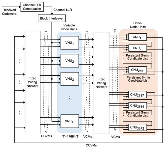
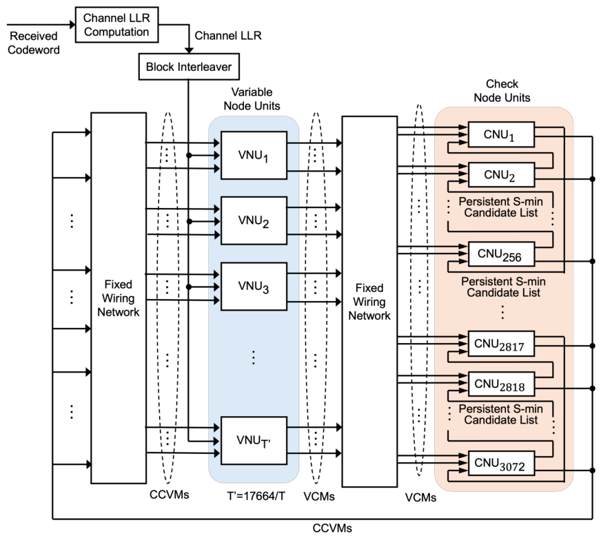
The architecture of the proposed decoder is developed by modifying the original phased decoder while preserving its hardware-efficient characteristics including the fixed wiring network, blockwise cyclic shift operations among CNUs, and the phase-based processing schedule, as shown in Figure 2. Since the proposed decoding procedure described in Section 3.1 is fully compatible with the original phased decoding framework, the overall datapath and interconnection network remain unchanged while the structure of CNUs and the transfer of CCVMs to VNUs are modified.
Figure 2.
Overall architecture of the proposed phased decoder with persistent S-min tracking.
The proposed decoder consists of three major functional blocks: the VNU, the CNU, and the fixed wiring network. The VNU generates VCMs using the channel LLRs and the CCVMs obtained in the previous phase. The generated VCMs are transferred to CNUs through the fixed wiring network, where the QC structure of the parity-check matrix enables message routing between VNUs and CNUs over fixed wiring networks, although different pairs of VNUs and CNUs need to be connected at different phases. Unlike the original phased decoder, in which CCVMs obtained in the previous iteration are stored and repeatedly used for all phases in the current iteration, the proposed decoder utilizes the newly updated CCVMs at every phase. Thus, CCVMs do not need to be stored in blockwise shift registers before they are input to VNUs as in the original phased decoder. Instead, CCVMs obtained in CNUs are directly input to VNUs, where correct routing for CCVM delivery is guaranteed by using blockwise cyclic shift operations among CNUs illustrated in the right part of Figure 2.
Following the phased decoding schedule, the parity-check matrix is partitioned into T column groups and one phase is processed at a time. For the 50G-PON LDPC codes with , each CNU receives at most two VCMs at each phase. Consequently, the CNU requires only two input ports regardless of the check-node degree, substantially reducing the hardware complexity compared with conventional column layered decoders. Since only one phase is active at any time, hardware resources are efficiently reused throughout all phases, resulting in a compact decoder architecture.
Different from the original phased decoder, whose CNU stores only the first and second minimum VCM magnitudes, the proposed decoder maintains an S-min candidate list in each CNU. The persistent candidate lists increase both the complexity of comparison logic and the number of registers in each CNU, resulting in additional LUT and FF utilization. Since the proposed decoding procedure is realized by modifying the fundamental hardware framework of phased decoding, the proposed decoder inherits the scalability and implementation efficiency of the phased decoder while supporting the continuous propagation of updated reliability information through the modified CNU architecture.
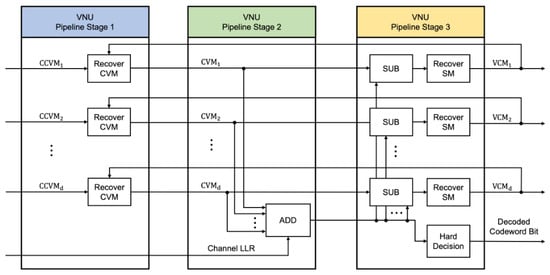
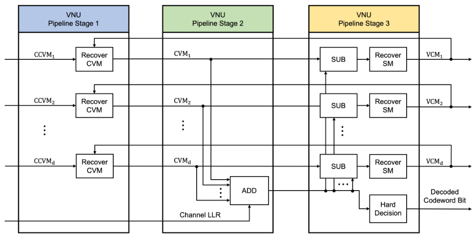
In the VNU, the delivered CCVMs are first recovered into the corresponding CVMs. The recovered CVMs are accumulated with the channel LLR to obtain the APP. A VCM is then generated by subtracting the CVM associated with the target check node from the APP. Thus, the VNU can be implemented using a three-stage pipeline, as shown in Figure 3.
Figure 3.
Three-stage pipelined structure of VNU.
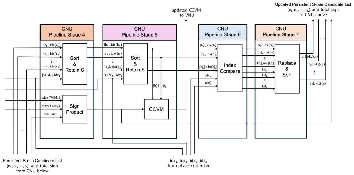
Before the CNU starts a process for a new phase, several preparatory operations are performed in the preceding phase. The indices of the variable nodes generating the VCMs that will arrive at each check node in the next phase are determined in advance. These indices correspond to the column indices of the parity-check matrix and are uniquely determined by the phase index and the CNU input port index. If these indices coincide with any entry of , the corresponding entry of is replaced by the pre-determined maximum value and the candidate list is sorted, after which an updated candidate list is ready for use. Then, the CNU enters a new phase by receiving the magnitudes and signs of two incoming VCMs. The two VCMs are compared with the candidate-list entries one by one, while the list is updated to retain its size of S. Then, the preprocessing for the subsequent CNU in the next phase is conducted as explained above. The above CNU operations can be implemented in a four-stage pipelined structure as shown in Figure 4. Note that the candidate tracking logic in the CNU is intentionally divided into two separate pipeline stages (Stage 6 for index comparison and Stage 7 for replacement and sorting) to break the long combinational path and achieve the high target operating frequency. In lower-frequency implementations, these two stages can be merged into a single stage to reduce the pipeline depth. The updated candidate list in each CNU is passed to the neighboring CNU in a blockwise cyclic manner, enabling dynamically matched VNUs and CNUs to exchange VCMs and CVMs according to the phase index. One phase is completed by executing the combined VNU and CNU pipeline sequentially, resulting in a total depth of seven pipeline stages.
Figure 4.
Four-stage pipelined structure of the proposed CNU implementing persistent S-min candidate list management.
3.3. Staggered Pipelined Structure for Continuous CCVM Update and Reuse
The proposed decoder inherits the staggered pipelined execution of the original phased decoder while fundamentally changing the manner in which CCVMs are updated and reused. In the phased decoder architecture, a new decoding phase enters the pipeline every clock cycle, allowing multiple phases to be processed simultaneously at different pipeline stages with a timing offset corresponding to a clock cycle. This staggered execution maximizes hardware utilization by continuously reusing the same VNU and CNU resources throughout all decoding phases.
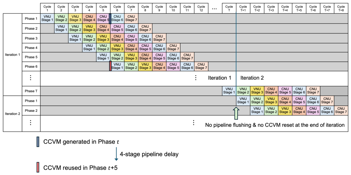
Figure 5 illustrates the timing relationship of the proposed decoder. Each pipeline consists of three VNU stages followed by four CNU stages, as introduced in Section 3.2. At the beginning of each phase, the VNU generates VCMs using the most recently available CCVMs. The updated CCVMs are generated after the VCMs pass through the three VNU stages and the first two CNU stages. Consequently, the updated CCVMs generated in phase t are not available at the beginning of the immediately following phase. Instead, they become available after a four-stage pipeline delay and are first reused in phase , as illustrated in Figure 5. Without the pipeline delay, the updated CCVMs would be available in phase .
Figure 5.
Timing diagram illustrating continuous CCVM update and reuse across consecutive decoding iterations without pipeline flushing.
An important characteristic of the proposed decoder is that the read-update-write process is repeated for every phase, regardless of the decoding iteration. Consequently, the iteration boundary simply represents the completion of one full sweep over all phases and does not introduce any interruption to the pipeline operation. As a result, CCVM is continuously refined and propagated throughout the entire decoding process. Since the decoder operates without pipeline flushing or candidate list reinitialization between consecutive iterations, the pipeline remains fully occupied after the initial filling period. This continuous operation improves pipeline utilization, accelerates the propagation of updated decoding information, and ultimately increases the throughput of a single decoder module while preserving the regular hardware structure and fixed wiring network of the original phased decoder.
4. Performance Evaluation
To evaluate the effectiveness of the proposed decoder, BER and BLER simulations, throughput analysis, and FPGA implementation are performed. The BER and BLER simulations are first conducted to investigate the intrinsic behavior of the proposed decoding algorithm, followed by hardware-aware simulations incorporating the staggered pipeline structure described in Section 3. Both the algorithm-level and hardware-aware BER and BLER results are obtained through software simulations. FPGA implementation is finally performed to evaluate the achievable operating frequency and hardware resource utilization, from which the decoding throughput is calculated based on the required number of clock cycles.
All simulations employ (17,280, 14,592) 50G-PON QC-LDPC codes specified in ITU-T G.9804.3 standard [5] adopting the NMSA-based decoding. The parity-check matrix is partitioned into 32 phases (), and the blockwise cyclic shift is applied to columns of to make each CNU receive at most two incoming VCMs. Based on extensive fixed-point simulations, we choose the normalization factor of NMSA in (2) as and apply 4-bit quantization to all LLR messages, i.e., channel LLRs, VCMs and CVMs, to obtain the low BER over a wide range of input BER. Note that among 4 quantized bits, one bit is assigned to the sign and three bits are used for representing a magnitude in an integer form. The demodulated hard bits of 0 and 1 are mapped to channel LLRs of and , respectively. The VCMs generated in the VNU are saturated to the range . In the CNU, the VCM magnitude selected through the minimum search is converted into an integer CVM magnitude such that 0, 1, 2, 3, 4, 5, 6, and 7 are mapped to 0, 1, 1, 2, 3, 4, 5, and 6, respectively [33]. This conversion provides an integer approximation of the normalization operation with . It follows that the bit-width of CCVM is 7 bits because CCVM contains the first and the second minimum magnitudes with the accumulated sign product. The index of VCM is represented by 6 bits because the column index of can be represented by a combination of phase index and CNU input port index, where 32 phases and 2 input ports can be expressed by 5 bits and 1 bit, respectively. Therefore, each entry of candidate magnitude list, , and the candidate index list, , are represented by 3 bits and 6 bits, respectively.
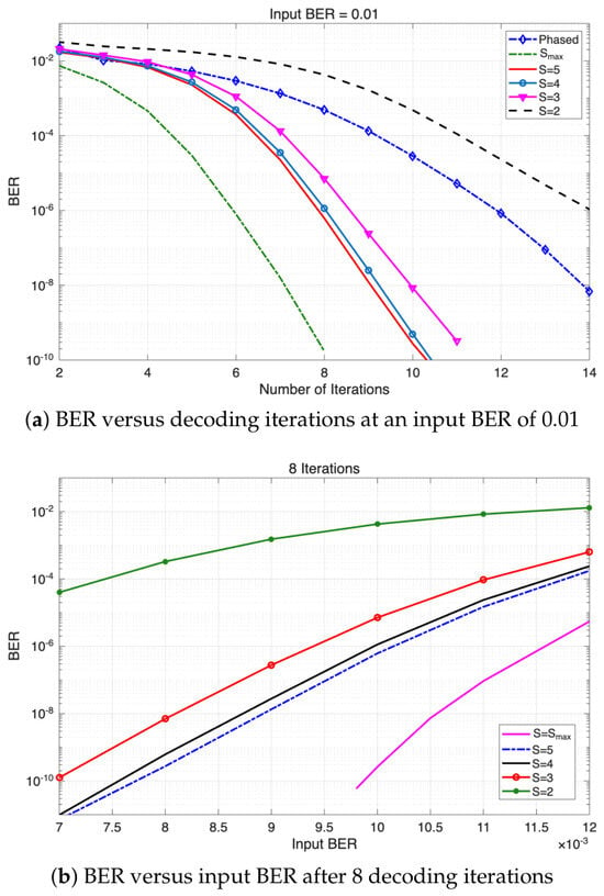
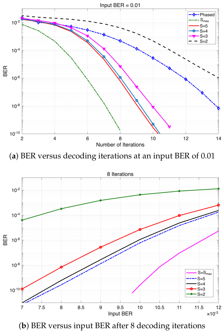
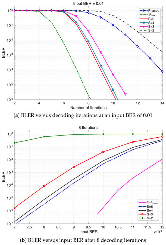
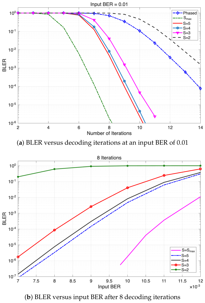
The BER and BLER performances of the proposed decoder are evaluated for various candidate list sizes, and , where corresponds to the ideal case in which all incoming VCMs are preserved in the candidate list. The BER and BLER results obtained with serve as reference performances for evaluating the effects of a limited candidate list size. Practical candidate list sizes are subsequently selected by jointly considering decoding performance and hardware implementation complexity.
All BER and BLER results were obtained directly through Monte Carlo simulations without estimation or extrapolation. For each simulation condition, random information blocks were generated and encoded, channel errors were introduced, and the resulting blocks were iteratively decoded. The BER and BLER were then calculated by directly counting the resulting numbers of bit and block error events, respectively. At each input BER, a sufficiently large number of information blocks was simulated to collect a sufficient number of error events. In particular, for very low BERs on the order of , the simulations were performed over a sufficient number of blocks to observe approximately 10 bit errors, while substantially more error events were observed at higher BERs.
4.1. BER and BLER Performances at the Algorithm Level
We first investigate the intrinsic error correction capability of the proposed decoding algorithm without considering the hardware-related timing effects such as a pipeline delay introduced in Section 3.3. Thus, the CCVMs updated at a certain phase are assumed to be immediately available for the next phase operation. Figure 6 shows BER performances of the conventional phased decoding and the proposed decoding with different sizes S of candidate list. The proposed decoding consistently outperforms the conventional phased decoding when because updated reliability information is continuously preserved and reused across consecutive phases. Interestingly, the proposed decoding with performs worse than the conventional phased decoding, suggesting that retaining only two candidates may lead to premature loss of useful reliability information during continuous phase-by-phase updates. As observed in Figure 6, increasing candidate list size gradually improves the BER performance. The proposed decoding with provides the best performance because all incoming VCMs updated at each phase are preserved in the candidate list without discarding any reliability information. However, the performance improvement gradually saturates as S increases, indicating that most of the decoding gain can be obtained by preserving only a limited number of minimum-value candidates. Based on this observation, we identify as promising sizes of candidate list and further evaluate the corresponding performances under practical hardware constraints in the following subsection.
Figure 6.
Algorithm-level BER performance of the proposed decoder with different candidate list sizes S.
Figure 7 shows the BLER performance of the conventional phased decoder and the proposed decoder with different candidate list sizes S. The BLER results exhibit trends similar to those observed in the BER simulations.
Figure 7.
Algorithm-level BLER performance of the proposed decoder with different candidate list sizes S.
4.2. BER and BLER Performances with Hardware Pipeline Effects
In order to achieve a high decoding throughput, a pipeline structure is employed in the hardware implementation of the proposed decoder. Consequently, unlike the algorithm-level evaluation, updated CCVMs become available after the pipeline delay introduced by the staggered execution schedule described in Section 3.3. Accordingly, hardware-aware software simulations are performed by incorporating the complete pipeline structure into the decoder model.
Unlike the algorithm-level evaluation, the practical selection of the candidate list size S must consider not only decoding performance but also the implementation complexity and timing constraints of the target hardware. As S increases, the candidate management logic becomes more complex, potentially increasing the required pipeline depth at a high operating frequency. For the target implementation considered in this work, the management of candidate list with and can be accommodated within the four-stage CNU pipeline as described in Section 3.2, whereas reduces the available timing margin and may require an additional pipeline stage to meet the target operating frequency. Accordingly, and seem appropriate values in the decoder hardware and are used in the subsequent hardware-aware evaluations.
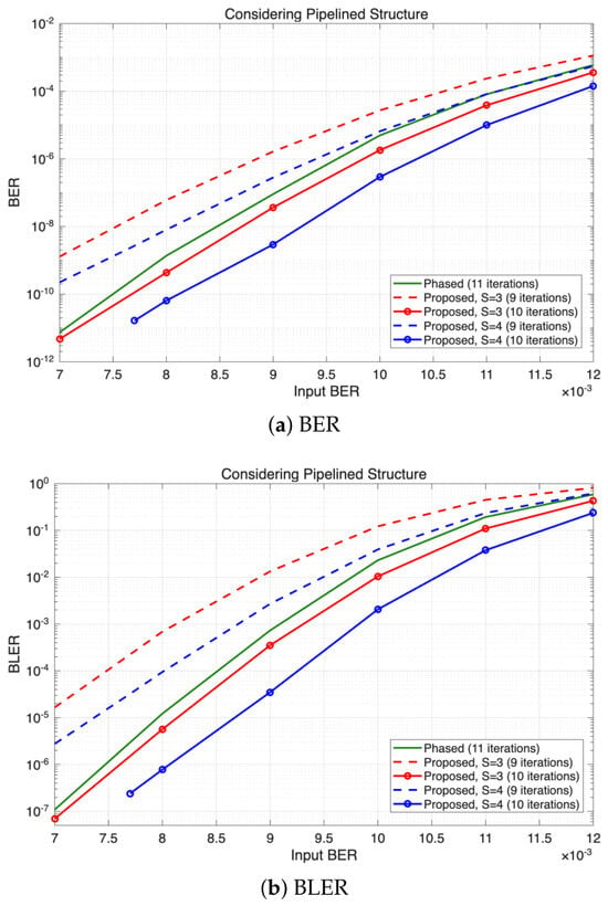
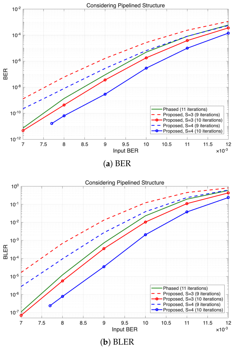
Figure 8 presents the BER and BLER performances obtained by 9 and 10 iterations of the proposed decoder with and considering the pipeline delay. As expected, the pipeline delay degrades decoding convergence compared with the algorithm-level evaluations given in Figure 6b and Figure 7b. Nevertheless, the proposed decoder still outperforms the conventional phased decoder. It is observed that the proposed decoder with and achieves nearly the same and lower BER, respectively, after 10 decoding iterations compared with the BER of conventional phased decoder after 11 iterations. A similar trend is observed in the BLER performance. This result demonstrates that continuously reusing updated CCVMs effectively accelerates information propagation across consecutive phases, allowing the same decoding performance to be achieved with fewer decoding iterations. At an input BER of 0.007, the proposed decoder with and was evaluated using 130 million information blocks. Since each information block contains 14,592 information bits, this corresponds to approximately tested information bits. Nine bit errors and nine block errors were observed, resulting in a BER and BLER of approximately and , respectively. Similarly, for and , information blocks, corresponding to approximately information bits, were simulated at an input BER of 0.0077. Twelve bit errors and twelve block errors were observed, resulting in a BER and BLER of approximately and , respectively.
Figure 8.
Hardware-aware BER and BLER performances incorporating the proposed pipelined architecture.
Since each decoding iteration requires a fixed number of clock cycles, reducing the required iteration count directly translates into a higher decoding throughput, which is further quantified in the following subsection.
4.3. BER and BLER Performances Versus Clock Cycles
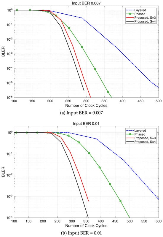
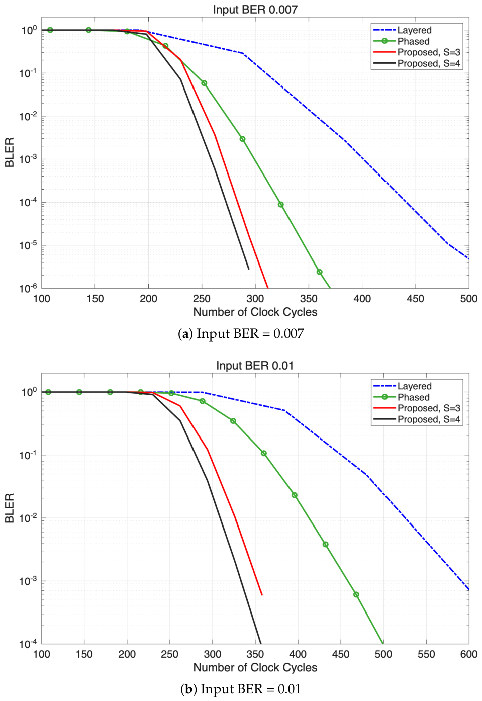
To evaluate decoding latency and throughput at target BER and BLER, we compare the clock cycle counts required by each decoder. A decoder requiring fewer clock cycles to achieve the target BER and BLER provides lower decoding latency and higher decoding throughput. The clock cycle counts are obtained from the hardware architectures described in Section 2 and Section 3.
First, we consider the conventional phased decoder as a reference. As introduced in Section 2.4, one phase is composed of 5 stages, where one iteration is completed by phases. The pipeline needs to be flushed at the end of every iteration, so that we require stages to complete one decoding iteration. Supposing each stage is processed within one clock cycle, the number of clock cycles required by iterations of the conventional phased decoder is .
Next, we consider the layered decoder. Since each layer is defined by 256 rows of the parity-check matrix , one decoding iteration is completed by updating all 12 layers. For a throughput-favorable comparison, we assume that all 256 CNUs within each layer operate fully in parallel. The VNU operation requires three pipeline stages, as in other decoders under comparison. Since each row in of 50G-PON LDPC codes has a weight of 22 or 23 [5], identifying the first and second minimum VCM magnitudes requires a comparison-tree depth of at least stages. We therefore assign five pipeline stages to the CNU, corresponding to the minimum comparison depth. Under these deliberately optimistic assumptions, processing one layer requires eight clock cycles, and the resulting best-case cycle count for decoding iterations is . Note that the clock-cycle count required by the layered decoder in the following comparison represents an optimistic best-case estimate under maximum hardware parallelism. Finally, we consider the proposed phased decoder with persistent S-min tracking. As introduced in Section 3.3, the pipeline does not need to be flushed at the end of every iteration. Considering 3 stages for VNU and 4 stages for CNU, the number of clock cycles required by iterations of the proposed decoder is .
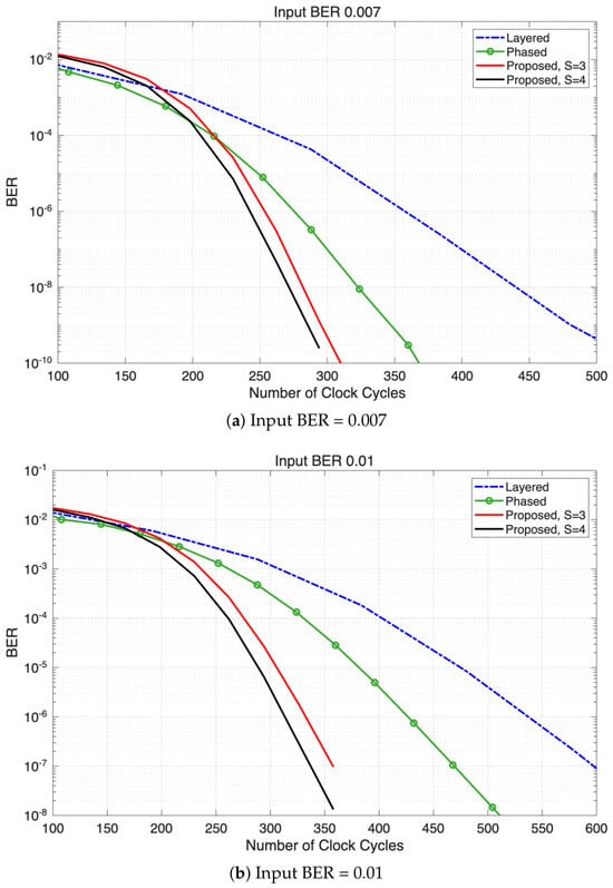
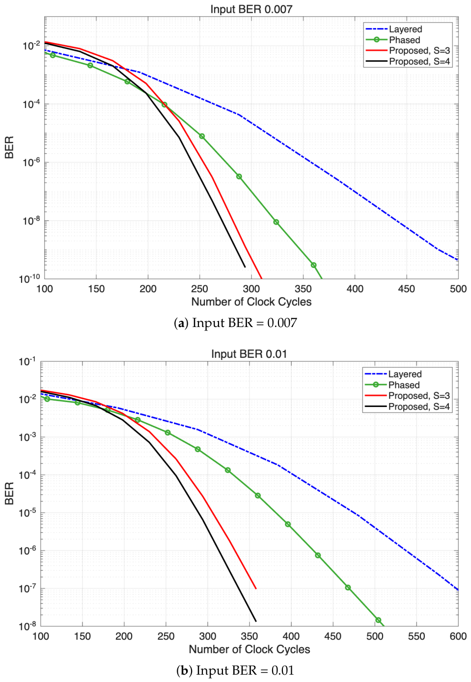
Figure 9 shows the BER performance as a function of the number of clock cycles obtained by the proposed decoder with and other decoders under comparison. It is observed that the proposed decoder requires fewer clock cycles to achieve a target BER than the conventional phased decoder and the layered decoder. For the proposed decoder, the number of clock cycles required to achieve a target BER can be reduced by using a larger candidate list size S, at the cost of higher implementation complexity. The advantage becomes particularly evident in the low BER region, where the proposed decoders reach a target BER with substantially fewer clock cycles than the reference decoders. These results confirm that the faster convergence provided by persistent candidate tracking directly translates into lower decoding latency and higher decoding throughput, even after the actual pipeline delay is taken into account. The same interpretation applies to the BLER results presented in Figure 10.
Figure 9.
BER versus the number of clock cycles for the layered decoder, conventional phased decoder, and the proposed decoder with and including the four-stage pipeline delay.
Figure 10.
BLER versus the number of clock cycles for the layered decoder, conventional phased decoder, and the proposed decoder with and including the four-stage pipeline delay.
4.4. FPGA Implementation Results
To verify the practical hardware efficiency of the proposed decoder, FPGA implementation is performed using a target device, AMD Kintex UltraScale+ XCKU19P FPGA operating at 388.8 MHz. Table 1 summarizes the hardware resource utilization of a single decoding module implemented in the proposed decoder architecture, together with that of the conventional phased decoder for comparison.
Table 1.
Hardware resource utilization of the conventional and proposed phased decoders.
The proposed decoder with uses approximately times as many LUTs and times as many FFs as the conventional phased decoder, whereas the proposed decoder with uses approximately times as many LUTs and times as many FFs. The increase in LUT utilization mainly results from the additional comparison and sorting logic required for persistent candidate tracking, whereas the increase in FF utilization originates from storing multiple candidate magnitudes together with their associated indices in each CNU. The proposed decoders with and achieve comparable BER performance, as observed in Figure 8 and Figure 9. However, the amount of hardware resources required for the decoders with and differs notably as shown in Table 1. Therefore, provides the most practical trade-off between BER performance and hardware resource utilization for the target FPGA implementation.
We compare the overall performance of the proposed decoder using with existing 50G-PON LDPC decoder implementations as shown in Table 2. For a fair comparison with the conventional phased decoder, the number of decoding iterations is determined according to the BER simulation results at an input BER of . Under this condition, the conventional phased decoder requires 11 decoding iterations to achieve a BER below approximately , whereas the proposed decoder with achieves comparable BER performance using only 10 decoding iterations. These decoding conditions are directly applied to the FPGA implementation, i.e., for the conventional phased decoder and for the proposed decoder. The decoding throughput is computed by
where is the operating frequency of FPGA, is the number of clock cycles corresponding to decoding iterations, and N is the LDPC codeword length. The throughput values reported in Table 2 are calculated using (3) with the operating frequencies obtained from FPGA implementation. It is observed that the proposed decoder improves the decoding throughput by 21.47% compared with the conventional phased decoder.
Table 2.
Comparison of LDPC Decoder Implementations.
The proposed decoder also achieves substantially higher decoding throughput than the layered decoders implemented in [31,32]. Since [31,32] operate at lower clock frequencies of 100 MHz and 75 MHz, respectively, their throughput values are additionally normalized to the 388.8 MHz operating frequency by assuming linear scaling with clock frequency. Under this favorable assumption for the layered decoders, the normalized throughputs of [31,32] are approximately 4.80 Gbps and 6.22 Gbps, respectively, which remain substantially lower than the 20.608 Gbps achieved by the proposed decoder. In practice, achieving such a high operating frequency would impose more stringent timing constraints on these implementations. Therefore, the frequency-normalized comparison indicates that the throughput advantage of the proposed decoder cannot be attributed solely to its higher operating frequency.
Compared with the conventional phased decoder, the implementation results demonstrate that the proposed decoder achieves higher throughput at the cost of additional hardware resources. Although additional logic is required to support persistent candidate tracking, the reduced number of decoding iterations shortens the decoding latency and increases the throughput of a single decoder module. Consequently, the proposed architecture achieves approximately 21.5% higher throughput than the conventional phased decoder while preserving the regular phase-based decoding framework and fixed-structured interconnection network. The FPGA implementation results confirm that the proposed decoder successfully converts the algorithmic convergence gain into practical throughput improvement.
For a comparison with the layered decoder reported in [37], the decoding throughput is evaluated in terms of codeword length N and the number of decoding iterations using a common operating frequency of 388.8 MHz. The decoder of [37] requires 270 clock cycles per layer and processes 12 layers per iteration, resulting in 3240 clock cycles per iteration. Accordingly, its frequency-normalized decoding throughput is expressed as Mbps. The throughput of the proposed decoder can be expressed as Mbps. Thus, under the same normalized conditions, the proposed decoder achieves substantially higher decoding throughput than the decoder reported in [37].
5. Discussion
The proposed decoder extends the conventional phased decoding framework by continuously maintaining and updating a limited candidate list across consecutive phases. Unlike the conventional phased decoder, which reinitializes CCVMs at every iteration boundary, the proposed decoder allows CCVMs to be updated at every phase and reused without interrupting the decoding process. This continuous reuse of updated reliability information improves decoding convergence and reduces the number of decoding iterations required to achieve a target BER.
The decoding performance gradually improves as the candidate list size increases, while the associated hardware complexity also increases. Although a larger candidate list preserves more reliability information, the performance improvement becomes marginal beyond a certain list size. For the target FPGA implementation considered in this work, candidate list sizes of and can be accommodated within the four-stage CNU pipeline, whereas may require additional pipeline stages to satisfy the target operating frequency. Considering both the hardware-aware BER performance and resource utilization, provides a practical trade-off between decoding performance and implementation complexity.
The increased resource utilization of the proposed decoder is largely associated with the additional storage and comparison logic required for candidate indices. The conventional phased decoder avoids variable-node index storage through direct comparison of VCM magnitudes. In contrast, persistent candidate tracking requires each retained magnitude to be associated with its originating variable-node index in order to prevent duplicated or stale candidate entries. Consequently, the proposed decoder introduces index-related storage and comparison logic. Therefore, the proposed decoder provides a design trade-off in which additional hardware resources are used to improve decoding convergence, decoding latency, and the throughput of a single decoder module while preserving the regular phase-based decoding framework.
The clock-cycle analysis further illustrates how the improved decoding convergence translates into practical hardware benefits. Faster convergence reduces the number of iterations, and consequently the number of clock cycles, required to achieve a given BER. The FPGA implementation confirms that this reduction results in a higher throughput for a single decoder module, although additional LUTs and FFs are required to support persistent candidate tracking.
The present implementation focuses on the standardized 50G-PON QC-LDPC codes and is designed for the relatively high target operating frequency of 388.8 MHz. Different LDPC code structures, operating frequencies, or hardware constraints may lead to different design choices for the candidate list size and pipeline organization. In particular, at a lower target operating frequency, the VNU and CNU operations could potentially be implemented with fewer pipeline stages. The resulting reduction in pipeline delay would allow updated CCVMs to propagate more rapidly across consecutive phases, which may further improve decoding convergence and reduce the required number of iterations. Detailed optimization for different operating frequencies is beyond the scope of this work, but extending the proposed approach to other QC-LDPC applications and investigating alternative hardware configurations would be worthwhile directions for future work.
6. Conclusions
We proposed a phased decoder with persistent S-min candidate tracking for 50G-PON QC-LDPC codes. The proposed decoding schedule continuously maintains a limited candidate list across consecutive decoding phases, allowing updated reliability information to be reused without interrupting the regular phased decoding process. A corresponding hardware architecture was developed while preserving the fixed wiring network and phased processing framework of the conventional phased decoder.
BER and BLER simulations showed that the proposed decoder reduces the number of decoding iterations required to achieve target error rates compared with the conventional phased decoder. Hardware-aware simulations further demonstrated that the convergence advantage is maintained even after considering the practical pipeline delay. FPGA implementation results indicated that the proposed decoder improves the throughput of a single decoder module by approximately 21.5% while requiring additional hardware resources for persistent candidate tracking. The frequency-normalized comparison with existing layered decoder implementations also indicates that the throughput advantage is not solely attributable to the higher operating frequency.
Overall, the presented results suggest that persistent S-min candidate tracking provides a practical extension of phased decoding for high-speed FPGA implementations of 50G-PON LDPC decoders. The proposed architecture offers an additional design option for applications where decoding latency and throughput are important design considerations.
Author Contributions
Conceptualization, J.W.L.; methodology, J.W.L.; software, H.L. and J.W.L.; validation, H.L.; formal analysis, H.L.; investigation, J.W.L.; resources, J.W.L.; data curation, H.L.; writing—original draft preparation, H.L. and J.W.L.; visualization, H.L. and J.W.L.; supervision, J.W.L.; project administration, J.W.L.; funding acquisition, J.W.L. All authors have read and agreed to the published version of the manuscript.
Funding
This research was supported by the Chung-Ang University Research Scholarship Grants in 2024 (34%). This research was supported by the IITP (Institute of Information & Communications Technology Planning & Evaluation)-ITRC (Information Technology Research Center) (IITP-2026-RS-2022-00156353, 33%) grant funded by the Korea government (MSIT) and by the National Research Foundation of Korea (NRF) grant funded by the Korea Government (MSIT) (RS-2024-00340852, 33%).
Data Availability Statement
The raw data supporting the conclusions of this article will be made available by the authors upon request.
Conflicts of Interest
The authors declare no conflicts of interest.
Abbreviations
The following abbreviations are used in this manuscript:
| PON | Passive optical networks |
| LDPC | Low-density parity-check |
| VNU | Variable node unit |
| CNU | Check node unit |
| VCM | Variable-to-check message |
| CVM | Check-to-variable message |
| CCVM | Compressed check-to-variable message |
| QC | Quasi-cyclic |
| MPA | Message passing algorithm |
| NMSA | Normalized min-sum algorithm |
| APP | A posteriori probability |
| LLR | Log-likelihood ratio |
| BER | Bit error rate |
| BLER | Block error rate |
| LUT | Look-up-table |
| FF | Flip-flop |
References
- Kim, K.O.; Doo, K.H.; Lee, H.H.; Kim, S.; Park, H.; Oh, J.Y.; Chung, H.S. High speed and low latency passive optical network for 5G wireless systems. J. Lightwave Technol. 2019, 37, 2873–2882. [Google Scholar] [CrossRef]
- Bonk, R.; Geng, D.; Khotimsky, D.; Liu, D.; Liu, X.; Luo, Y.; Nesset, D.; Oksman, V.; Strobel, R.; Van Hoof, W. 50G-PON: The first ITU-T higher-speed PON system. IEEE Commun. Mag. 2022, 60, 48–54. [Google Scholar] [CrossRef] [Scilit]
- Zhang, D.; Liu, D.; Wu, X.; Nesset, D. Progress of ITU-T higher speed passive optical network (50G-PON) standardization. J. Opt. Commun. Netw. 2020, 12, D99–D108. [Google Scholar] [CrossRef] [Scilit]
- International Telecommunication Union. G.9804.2: Higher Speed Passive Optical Networks—Common Transmission Convergence Layer Specification. ITU-T Recommendation G.9804.2. Available online: https://www.itu.int/rec/T-REC-G.9804.2 (accessed on 30 September 2021).
- International Telecommunication Union. G.9804.3: 50-Gigabit-Capable Passive Optical Networks (50G-PON): Physical Media Dependent (PMD) Layer Specification. ITU-T Recommendation G.9804.3. Available online: https://www.itu.int/rec/T-REC-G.9804.3 (accessed on 20 December 2021).
- Luo, Y.; Effenberger, F. What is beyond 50G: Future standards of optical access networks. J. Opt. Commun. Netw. 2024, 16, C106–C112. [Google Scholar] [CrossRef] [Scilit]
- Schmalen, L.; van Wijngaarden, A.J.; ten Brink, S. Forward error correction in optical core and optical access networks. Bell Labs Tech. J. 2013, 18, 39–66. [Google Scholar] [CrossRef] [Scilit]
- Buerner, T.; Dohmen, R.; Zottmann, A.; Saeger, M.; van Wijngaarden, A.J. On a high-speed Reed-Solomon coded architecture for 43 Gb/s optical transmission systems. In Proceedings of the International Conference on Microelectronics, Nis, Serbia, 16–19 May 2004; pp. 743–746. [Google Scholar]
- International Telecommunication Union. G.984.3: Gigabit-Capable Passive Optical Networks (G-PON): Transmission Convergence Layer Specification; ITU-T Recommendation G.984.3. Available online: https://www.itu.int/rec/T-REC-G.984.3 (accessed on 28 February 2004).
- Gallager, R.G. Low-density parity-check codes. IRE Trans. Inf. Theory 1962, 8, 21–28. [Google Scholar] [CrossRef] [Scilit]
- Richardson, T.J.; Urbanke, R.L. The capacity of low-density parity-check codes under message-passing decoding. IEEE Trans. Inf. Theory 2001, 47, 599–618. [Google Scholar] [CrossRef] [Scilit]
- Fossorier, M.P.; Mihaljević, M.; Imai, H. Reduced complexity iterative decoding of low-density parity check codes based on belief propagation. IEEE Trans. Commun. 1999, 47, 673–680. [Google Scholar] [CrossRef] [Scilit]
- Chen, J.; Dholakia, A.; Eleftheriou, E.; Fossorier, M.P.C.; Hu, X.-Y. Reduced-complexity decoding of LDPC codes. IEEE Trans. Commun. 2005, 53, 1288–1299. [Google Scholar] [CrossRef] [Scilit]
- Fossorier, M.P. Quasi-cyclic low-density parity-check codes from circulant permutation matrices. IEEE Trans. Inf. Theory 2004, 50, 1788–1793. [Google Scholar] [CrossRef] [Scilit]
- Tanner, R.M.; Sridhara, D.; Sridharan, A.; Fuja, T.E.; Costello, D.J., Jr. LDPC block and convolutional codes based on circulant matrices. IEEE Trans. Inf. Theory 2004, 50, 2966–2984. [Google Scholar] [CrossRef] [Scilit]
- Wang, Z.; Cui, Z. Low-complexity high-speed decoder design for quasi-cyclic LDPC codes. IEEE Trans. Very Large Scale Integr. (VLSI) Syst. 2007, 15, 104–114. [Google Scholar] [CrossRef] [Scilit]
- Hocevar, D.E. A reduced complexity decoder architecture via layered decoding of LDPC codes. In Proceedings of the IEEE Workshop on Signal Processing Systems (SiPS), Austin, TX, USA, 13–15 October 2004; pp. 107–112. [Google Scholar]
- Zhang, J.; Fossorier, M.P. Shuffled iterative decoding. IEEE Trans. Commun. 2005, 53, 209–213. [Google Scholar] [CrossRef]
- Sharon, E.; Litsyn, S.; Goldberger, J. An efficient message-passing schedule for LDPC decoding. In Proceedings of the 23rd IEEE Convention of Electrical and Electronics Engineers in Israel, Tel Aviv, Israel, 6–7 September 2004; pp. 223–226. [Google Scholar]
- Cui, Z.; Wang, Z.; Zhang, X. Reduced-complexity column-layered decoding and implementation for LDPC codes. IET Commun. 2011, 5, 2177–2186. [Google Scholar] [CrossRef] [Scilit]
- Zhang, K.; Huang, X.; Wang, Z. High-throughput layered decoder implementation for quasi-cyclic LDPC codes. IEEE J. Sel. Areas Commun. 2009, 27, 985–994. [Google Scholar] [CrossRef] [Scilit]
- Kim, S.; Sobelman, G.E.; Lee, H. A reduced-complexity architecture for LDPC layered decoding scheme. IEEE Trans. Very Large Scale Integr. (VLSI) Syst. 2011, 19, 1099–1103. [Google Scholar] [CrossRef] [Scilit]
- Li, Y.; Li, Y.; Ye, N.; Chen, T.; Wang, Z.; Zhang, J. High throughput priority-based layered QC-LDPC decoder with double update queues for mitigating pipeline conflicts. Sensors 2022, 22, 3508. [Google Scholar] [CrossRef] [Scilit]
- Chen, Y.; Parhi, K.K. Overlapped message passing for quasi-cyclic low-density parity check codes. IEEE Trans. Circuits Syst. I Regul. Pap. 2004, 51, 1106–1113. [Google Scholar] [CrossRef]
- Cui, Z.; Wang, Z.; Liu, Y. High-throughput layered LDPC decoding architecture. IEEE Trans. Very Large Scale Integr. (VLSI) Syst. 2009, 17, 582–587. [Google Scholar] [CrossRef] [Scilit]
- Mansour, M.M.; Shanbhag, N.R. High-throughput LDPC decoders. IEEE Trans. Very Large Scale Integr. (VLSI) Syst. 2003, 11, 976–996. [Google Scholar] [CrossRef] [Scilit]
- Onizawa, N.; Hanyu, T.; Gaudet, V.C. Design of high-throughput fully parallel LDPC decoders based on wire partitioning. IEEE Trans. Very Large Scale Integr. (VLSI) Syst. 2010, 18, 482–489. [Google Scholar] [CrossRef] [Scilit]
- Lee, H.-C.; Ueng, Y.-L. LDPC decoding scheduling for faster convergence and lower error floor. IEEE Trans. Commun. 2014, 62, 3104–3113. [Google Scholar] [CrossRef] [Scilit]
- Choe, J.; Lee, Y. Cost-efficient partially-parallel LDPC decoder architecture for 50G-PON standard. In Proceedings of the International SoC Design Conference (ISOCC), Sapporo, Japan, 19–22 August 2024; pp. 318–319. [Google Scholar]
- Jiang, M.; Xu, Q.; Zhao, C. Layered ternary message passing decoder of LDPC codes for 50G-PON. Opt. Lett. 2025, 50, 2187–2190. [Google Scholar] [CrossRef] [Scilit]
- Wang, J.; Yang, J.; Zhang, G.; Zeng, X.; Chen, Y. Efficient layered parallel architecture and application for large matrix LDPC decoder. Electronics 2023, 12, 3784. [Google Scholar] [CrossRef] [Scilit]
- Wang, W.; Tao, K.; Qian, W.; Cai, Y.; Lei, M.; Zhou, X.; Chien, H.-C.; Liang, J.; Zhang, S.; Liu, Z. Real-time FPGA verification for 25G-PON and 50G-PON LDPC codes. In Proceedings of the Conference on Lasers and Electro-Optics (CLEO), Washington, DC, USA, 10–15 May 2020. Paper STh3L.5. [Google Scholar]
- Kwon, K.-W.; Kim, K.; Doo, K.; Chung, H.; Lee, J.W. Low-complexity architecture for high-speed 50G-PON LDPC decoder. IEEE Access 2025, 13, 28751–28765. [Google Scholar] [CrossRef] [Scilit]
- Tanner, R.M. A recursive approach to low complexity codes. IEEE Trans. Inf. Theory 1981, 27, 533–547. [Google Scholar] [CrossRef] [Scilit]
- Chen, J.; Fossorier, M.P. Density evolution for two improved BP-based decoding algorithms of LDPC codes. IEEE Commun. Lett. 2002, 6, 208–210. [Google Scholar] [CrossRef] [Scilit]
- Chen, X.; Lin, S.; Akella, V. QSN—A simple circular-shift network for reconfigurable quasi-cyclic LDPC decoders. IEEE Trans. Circuits Syst. II Express Briefs 2010, 57, 782–786. [Google Scholar] [CrossRef] [Scilit]
- Yang, M.; Li, L.; Liu, X.; Djordjevic, I.B. Real-time verification of soft-decision LDPC coding for burst mode upstream reception in 50G-PON. J. Lightwave Technol. 2020, 38, 1693–1701. [Google Scholar] [CrossRef] [Scilit]



Disclaimer/Publisher’s Note: The statements, opinions and data contained in all publications are solely those of the individual author(s) and contributor(s) and not of MDPI and/or the editor(s). MDPI and/or the editor(s) disclaim responsibility for any injury to people or property resulting from any ideas, methods, instructions or products referred to in the content. |
© 2026 by the authors. Licensee MDPI, Basel, Switzerland. This article is an open access article distributed under the terms and conditions of the Creative Commons Attribution (CC BY) license.