


Abstract
Efficient mixing in stirred tanks is essential for chemical and biochemical processes. Tubular baffles offer potential energy savings and multifunctionality (e.g., as heat exchangers); however, their interaction with common impeller types is not well understood. This study uses computational fluid dynamics (CFD) simulations to evaluate the hydrodynamic performance of a novel tubular baffle design compared to conventional flat baffles with three impellers: a Rushton turbine (RT), a pitched blade turbine (PBT), and a hydrofoil (HE3). Dimensionless analysis (power number, NP; and pumping number, NQ), flow visualization, and vorticity dynamics were employed. The results show that, by attenuating large-scale recirculation, tubular baffles reduce power consumption by 64%, 13%, and 23% for the HE3, PBT, and RT, respectively. However, the HE3 impeller experienced a 30% decrease in pumping capacity, which confined the flow to the lower tank. The PBT showed a 10% increase in NQ and intensified bottom circulation. The RT uniquely generated distributed, high-intensity turbulence along the baffle height while maintaining its characteristic dual-loop structure. The analysis critiques the local pumping efficiency metric and advocates for a global flow assessment. The HE3 is optimal for efficient bulk blending at low power; the PBT is optimal for strong bottom circulation processes; and the RT is optimal for applications requiring enhanced interfacial processes, where baffles serve a dual function. This work provides a framework for selecting energy-efficient agitation systems by coupling impeller performance with global tank hydrodynamics.
1. Introduction
In numerous industrial processes, from pharmaceuticals to mining, achieving the perfect mixture is not just a goal, it is a necessity. At the heart of this operation lies the stirred tank [1]. These versatile vessels provide essential agitation for a wide variety of applications, such as homogenizing active ingredients [2], dispersing gases [3], and breaking down particles to improve mass transfer [4].
The flow inside a stirred tank is governed by the interaction between the impeller and the baffle, as well as the predominant discharge direction of the impeller. Axial-flow impellers, such as pitched-blade turbines (PBTs), generate a strong circulation loop that drives fluid downwards towards the bottom of the tank and upwards along the walls. High-efficiency hydrofoil impellers, such as the Chemineer HE-3, are part of the axial-flow family. Yet they offer a similar pumping capacity while consuming significantly less power [5]. In contrast, radial-flow impellers, such as the Rushton turbine, discharge fluid horizontally, creating two independent circulation loops above and below the impeller plane. Although this pattern does not achieve perfect global mixing, it repeatedly passes fluid through the high-shear region near the blade tips. This makes radial impellers ideal for processes where micromixing is important [6].
Due to their critical role, engineers are constantly refining stirred tank designs to save energy without compromising performance One key area of innovation is the impeller, which is the rotating component that drives the mixing action. For instance, a research team redesigned the traditional Rushton impeller by incorporating perforations. This modification reduced energy consumption while maintaining the same flow patterns [7]. This modification reduced energy consumption while maintaining the same flow patterns. Similarly. In a related study, researchers proposed modifying the shape of the blades of a pitched blade turbine (PBT) impeller [8]. The redesigned blades significantly reduced the overall energy consumption of the system while promoting a more stable flow with reduced turbulent vortex shedding. These vortices promote better circulation of the liquid inside the tank, which could lead to more efficient, homogeneous mixing.
Although much research focuses on impellers, the performance of the mixing system is a synergy of all components. Recent innovations have thus targeted baffle redesign. In 2022, Zhou et al. investigated sine-wave baffles and found that they could provide adequate mixing with altered flow structures [9]. Similarly, single surface-level baffles [10] and control rods attached to impellers [8] have been proposed to suppress vortices and reduce power consumption. One of the most promising designs involves replacing conventional flat baffles with tubular ones or banks of tubes. The primary reported advantage is a significant reduction in the power required to rotate the impeller, which is achieved by minimizing resistance to tangential flow.
However, a critical gap remains in the literature. While the power-saving benefit of tubular baffles is well-established, their complex, impeller-specific interactions, as well as the consequent alterations to global flow patterns, turbulence distribution, and process-oriented performance, have not been adequately quantified. Previous studies often focus on a single impeller type or lack a detailed analysis of the flow-impeller-baffle interaction.
This study addresses this gap by systematically comparing the hydrodynamics induced by three fundamentally different impellers (radial RT, axial PBT, and high-efficiency axial HE3) in tanks with either conventional or tubular baffles. This work is novel in its coupled analysis of local impeller metrics NP and NQ and global tank-wide flow patterns, vorticity dynamics, and axial flow decay. This approach reveals that the optimal impeller-baffle pairing depends heavily on the process objective, challenging the simplistic view of tubular baffles as merely a low-power substitute. Our goal is to establish a framework for strategically selecting and designing energy-efficient agitated systems that use tubular baffles.
2. Materials and Methods
2.1. Configurations of the Stirred Tank
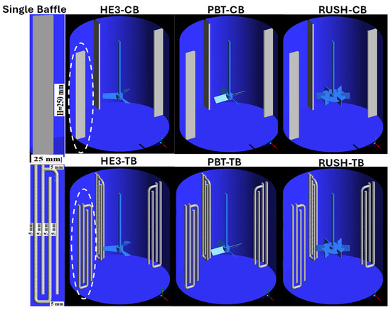
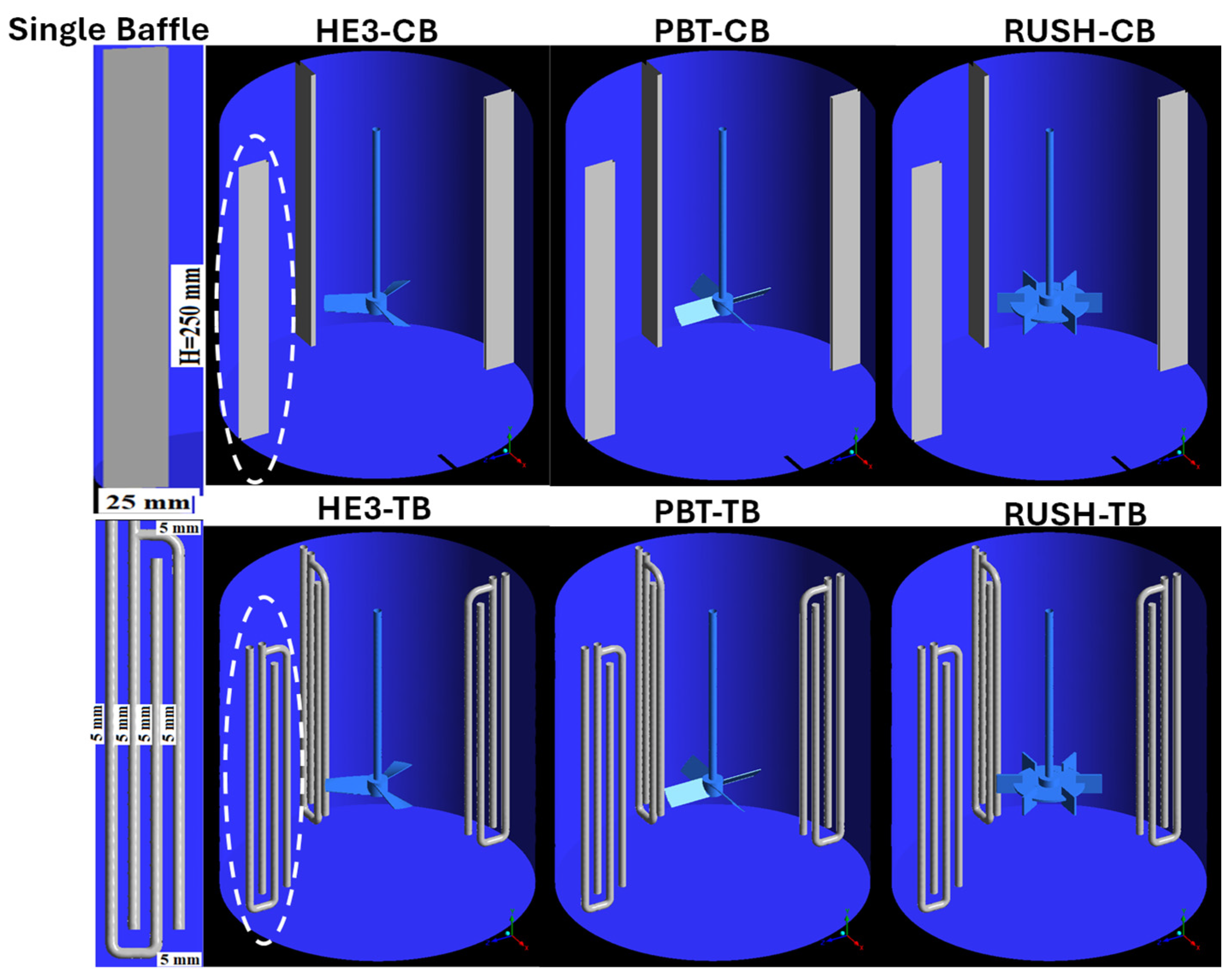
This study used a mechanically stirred system consisting of a horizontal cylindrical tank with a volume of 12 L. For comparison, a conventional baffle system was employed (Figure 1). The tank’s geometric dimensions were T = H = 0.25 m, and the setup included four equally spaced flat baffles, each with a width of T/10.
Figure 1.
Configurations of conventional (top) and tubular (bottom) baffles, the white dashed line marks a single baffle, shown in more detail on the left of the image.
Three types of impellers were tested: a pitched blade turbine with four blades inclined at 45°, a six-blade Rushton turbine with flat blades, and an HE3 type impeller with inclined blades. Each impeller had a diameter of 83.3 mm and was positioned with a bottom clearance of T/3. A motor maintained a constant angular velocity of 8.33 rad/s (500 rpm). The working fluid was water with a density of 998.2 kg/m3 and a dynamic viscosity of 0.001003 Pa·s.
This study examined the impact of tubular baffles on global parameters, such as torque and flow through the impeller, and their influence on flow patterns resulting from impeller baffle interaction. To this end, four sets of tubular baffles were installed, as shown in Figure 1. Each baffle consisted of four cylindrical tubes, each with a diameter of 6 mm, spaced 5 mm apart Figure 1. This geometry was chosen as a model representative of a compact tube bundle. The tube diameter is comparable to those used in small-scale shell-and tube heat exchangers. The spacing allows for significant fluid passage, which mitigates pressure drops, a common issue in such equipment [11,12].
2.2. Torque Measurements
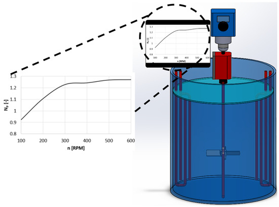
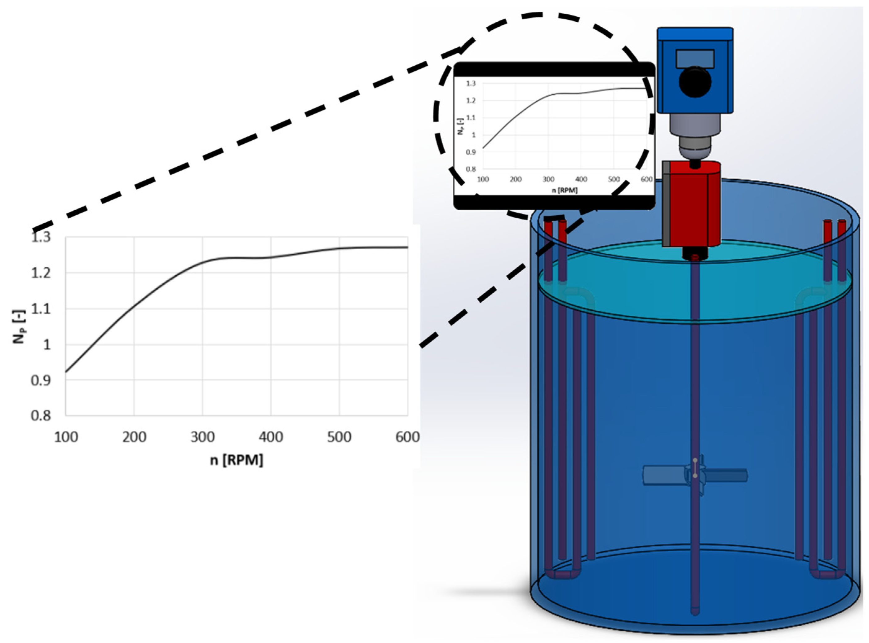
To validate the power consumption results obtained from our numerical simulations, we used an experimental technique with a dynamic torque sensor (Futek®). The sensor was coupled directly to the shaft connecting the impeller and the motor, as illustrated in Figure 2.
Figure 2.
Experimental setup torque measurement.
This setup allowed us to capture approximately 18,000 torque measurements using the SENSIT® software Version 2.13. Due to the inherently turbulent nature of the agitated system, the resulting torque data required averaging to yield a stable value. We then used this averaged torque to calculate the power consumption through Equation (1).
where N is the angular velocity in s−1, and τ is the torque in N·m, which is obtained with the experimental system.
2.3. CFD Model Equations
The fluid flow within the rotating domain (RRF volume) was modeled using Reynolds-averaged Navier–Stokes (RANS) equations [13]. The Moving Reference Frame (MRF) approach was employed to account for the rotation of the inner zone without physically rotating the mesh. In this formulation, the governing equations of flow are solved in a rotating frame of reference. This requires the addition of extra source terms to the momentum equation to represent inertial forces. The continuity equation for incompressible flow is given by Equation (2).
The momentum conservation equation, modified for the rotating reference frame, is expressed as show in Equation (3).
Here, is the mean velocity component, is the position vector and is the mean pressure, ρ and µ represents the fluid density and viscosity, denotes the delta de Kronecker. The term represents the Reynolds stress tensor, which introduces a closure problem for the average momentum equation. The Boussinesq hypothesis is commonly used to resolve this issue in two-equation models, such as k-ε and k-ω. This hypothesis relates Reynolds stresses to the mean rate of deformation via turbulent viscosity .
This formulation introduces turbulent kinetic energy (k), a scalar defined by velocity fluctuations. Various RANS models propose different methods for calculating and k, often employing approximations tailored to specific flow regimes. For this study, the realizable k-ε model was chosen. This model solves separate transport equations for k and ε, accounting for effects such as convection and diffusion. Although the standard k-ε model is widely used in industrial applications due to its robustness and computational efficiency, it has limitations in flows with strong adverse pressure gradients and large streamline curvatures. The realizable variant addresses some of these shortcomings and provides improved performance for flows such as turbulent jets [14], making it a suitable choice for the complex flow patterns generated by impellers in a baffled tank.
Crucially, the term accounts for the effects of the rotating coordinate system. According to [15], this source term encompasses both the Coriolis force (the first term of Equation (5)) and the centrifugal force (the second term of Equation (5)).
In these expressions, is the angular velocity vector of the moving reference frame relative to the inertial frame, and is the position vector extending from the origin of the rotating system. These terms serve to correct the momentum transport for the rotation of the domain.
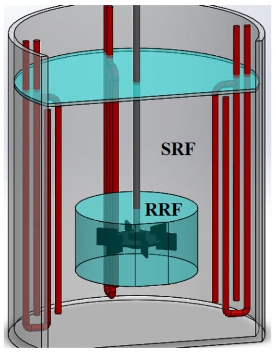
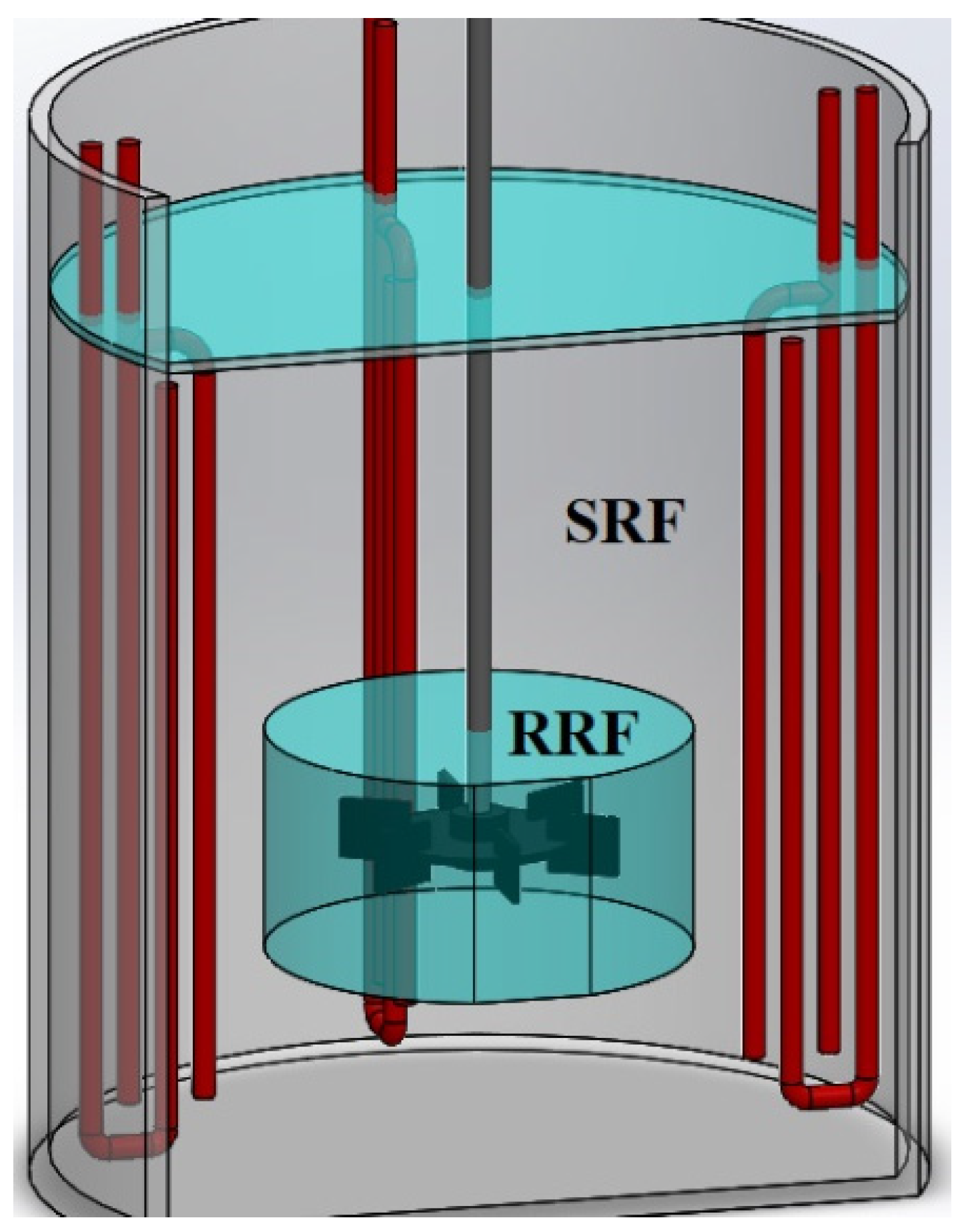
The simulations used a Reynolds averaged Navier–Stokes (RANS) model to capture time averaged flow behavior under steady state conditions. To simulate the rotation of the impeller without requiring a new mesh, the multiple reference frame (MRF) approach was adopted [16]. In this model, a cylindrical subdomain enclosing the impeller was designated the MRF and assigned an angular velocity. The rest of the tank was treated as a rotating reference frame (RRF). This setup efficiently captures the interaction between the rotating impeller and stationary tank components, as illustrated in Figure 3.
Figure 3.
Computational domain of the agitated tank illustrates the zones used for the Multiple Reference Framework (MRF) approach.
The flow in stirred tanks at the operating condition (Re > 20,000) is fully turbulent. To close the RANS equations, the realizable k-ε model was selected. This model solves separate transport equations for the turbulent kinetic energy (k) and its dissipation rate (ε), providing a robust and computationally efficient framework for complex industrial flows [14,17]. The realizable variant offers improved performance over the standard k-ε model for flows involving strong streamline curvature, rotation, and recirculation—characteristics prevalent in impeller discharges and baffled tanks [18]. The standard wall functions were applied to model the near-wall flow. This model choice represents a suitable compromise between accuracy and computational cost for capturing the mean flow and turbulent scales relevant to mixing performance assessment.
2.4. Details of the Numerical Solution
The computational domain was created using ANSYS DesignModeler. Because of the complex geometry of the tubular baffles, the mesh only consisted of tetrahedral elements, which were generated using the ANSYS Meshing module. Local mesh refinement was performed in critical regions such as the impeller discharge zone, where the highest velocities are expected, and around the baffles. To ensure solution accuracy, we maintained high mesh quality by keeping skewness values below 0.25 and orthogonality values above 0.8. All simulations were conducted using the FLUENT CFD software with double precision on a workstation equipped with a 4-core, 3.7 GHz AMD Ryzen processor. The SIMPLE algorithm was used for pressure-velocity coupling. To maintain numerical stability, second-order discretization schemes were applied to all variables, and the convergence residuals were set to 1 × 10⁻⁶. The no-slip wall condition and the standard wall function were imposed on all solid surfaces in contact with the fluid, regardless of whether the surfaces were stationary or moving. Specifically, zero velocity was prescribed at the stationary walls (i.e., the tank walls and deflector structures) in the absolute frame of reference. Meanwhile, the velocity at the impeller surfaces was set equal to the local velocity of the rotating reference frame. Additionally, a symmetry boundary condition was applied to the free liquid surface to enforce zero shear stress, consistent with the negligible surface deformation observed experimentally.
2.5. Evaluation of Turbulent Flow in Agitated Tanks
There are several criteria in the literature for evaluating the performance of an agitated tank. The most common approach uses dimensionless numbers. The Reynolds number Equation (6), which relates inertial to viscous forces, is used to classify the flow regime. Turbulent conditions (Re > 20,000) are typically targeted to enhance mixing efficiency.
Similarly, power and pumping Equations (7) and (8) numbers are key parameters. They relate design parameters (e.g., impeller diameter) and operational conditions (e.g., agitation speed) to the power consumption and flow rate generated by the impeller within its sweep zone.
Combining the power and pumping numbers of yields the pumping efficiency Equation (9), a characteristic parameter for any given system. This metric identifies impellers that achieve higher fluid flow through their active region with lower energy input. Since this parameter focuses on flow in the immediate vicinity of the impeller, it is effective in evaluating the impact of impeller geometry changes on flow patterns and power drawing.
However, a key limitation of pumping efficiency arises when geometric modifications are made to the baffles. Since baffles influence the flow throughout a larger volume of the tank, a local metric near the impeller is insufficient. To address this, this study suggests using the axial pumping number Equation (10), which evaluates flow at different tank heights, combined with the turbulent energy dissipation rate across the entire tank volume Equation (11).
where ρ is the fluid density (kg⋅m−3), N is the impeller speed (s−1), D is the impeller diameter (m), μ is the dynamic viscosity (Pa⋅s), P is the impeller power input (W), is the volumetric flow rate discharged through the effective area swept by the impeller (m3·s−1) and is the axial flow rate (m3·s−1) obtained by integrating the positive axial velocity through a cross section of the tank at various heights.
2.6. Mesh Independence and Turbulence Model Evaluation
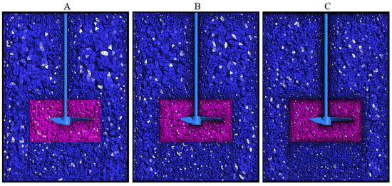
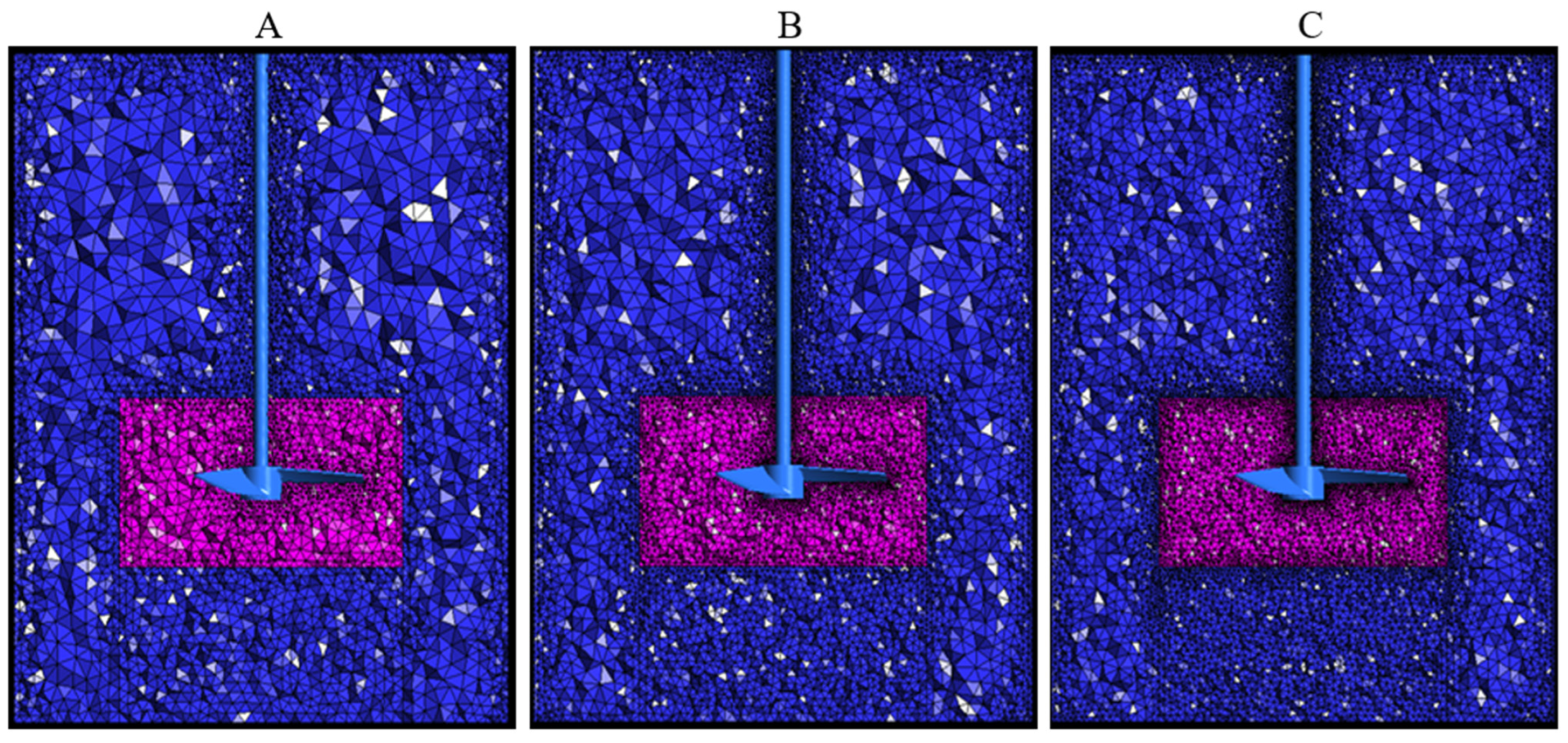
To ensure that the numerical simulations accurately predicted the behavior of the fluids within the proposed stirred tanks, a rigorous methodology was employed to guarantee mesh independence. This methodology uses the Mesh Convergence Index (GCI) to generate meshes with approximately twice the number of elements (r ≈ 2). It concentrates refinement in areas of high velocity, such as the impeller environment, the discharge region, the area beneath the impeller (HE3 and PBT), and the area surrounding the Rushton-type impeller, as shown in Figure 4.
Figure 4.
The meshes generated for the case with flat deflectors and an HE3-type impeller are categorized as follows: (A) coarse, (B) medium and (C) fine, the pink region indicates the moving reference frame (MRF), while the blue region denotes the stationary reference frame (SRF).
Once the simulations had been completed, a global parameter was extracted. In this case, this corresponded to the torque used to generate the mixture within the tank. The grind convergence index is defined by (12).
Here, f represents the torque value, while the subscripts i and j correspond to the values obtained between two different meshes. The term corresponds to a safety factor of 1.25 used when three meshes are generated, and m represents the convergence order of the solution, calculated using (13). Finally, the asymptotic convergence range (asyR), defined in (14), indicates whether the solution has converged; the convergence criterion is asyR ≈ 1.
The GCI-based approach enables a global variable to be used to guarantee mesh independence.
3. Results and Discussions
3.1. Mesh Independence Analysis
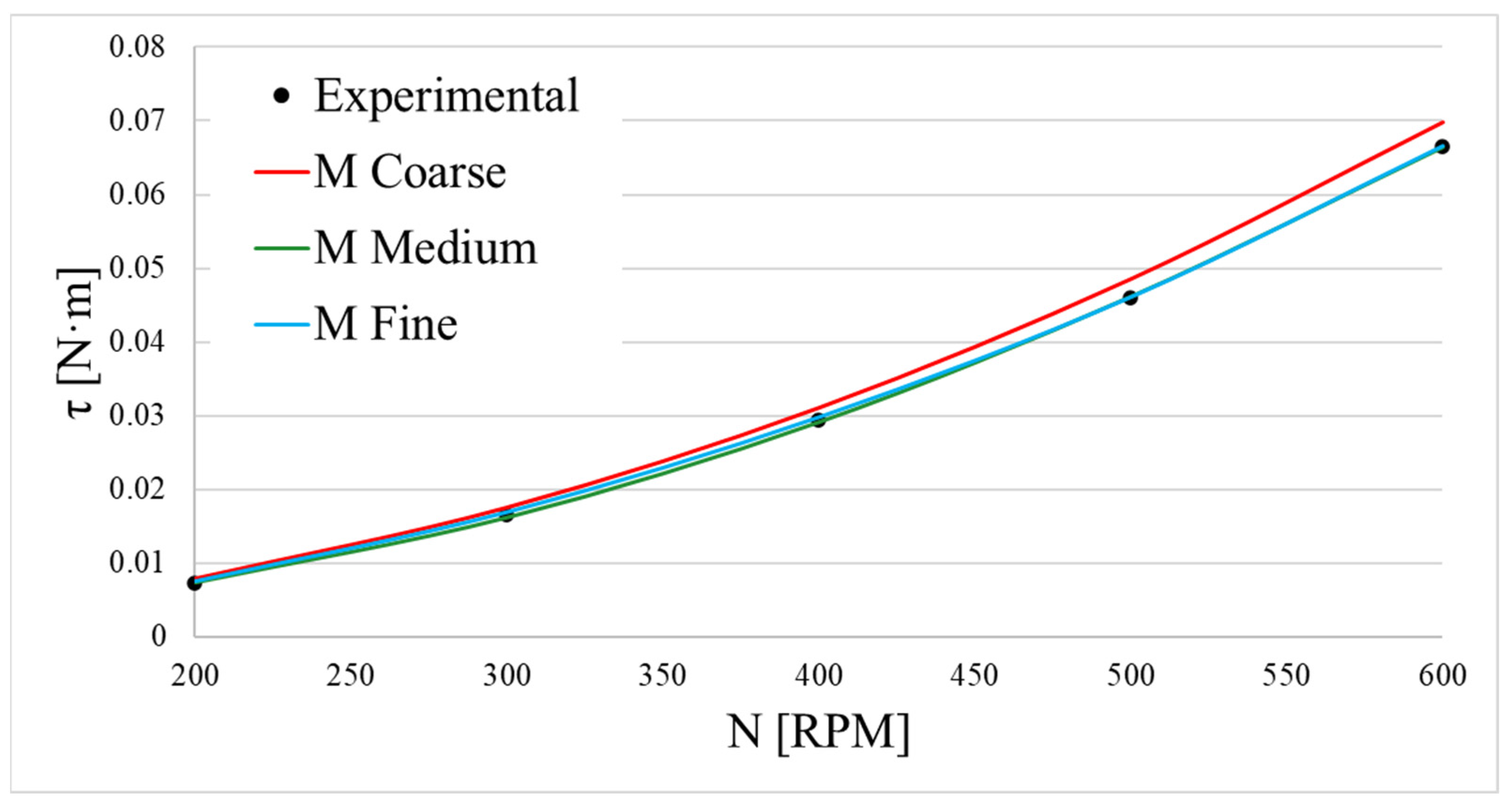
A mesh sensitivity study was conducted to ensure that the numerical results were independent of spatial discretization. Figure 5 shows how the computed torque for the PBT impeller with four tubular baffles changes as the number of mesh elements increases. Three systematically refined meshes (coarse, medium, and fine) were generated. The results show that, as the number of elements increases, the numerical simulation results progressively approach the values obtained through experimentation. This procedure was performed at different agitation speeds and for three different impeller types, yielding consistent results in all cases. Based on this methodology, the medium mesh was determined to be capable of accurately predicting fluid behavior inside the tank. To further increase confidence in the results, the grid convergence index (GCI) methodology described previously was also applied.
Figure 5.
Torque convergence with mesh refinement for the PBT impeller with four tubular baffles.
Table 1 shows the results of the mesh independence analysis and the torque for the different cases. In all cases analyzed, the values obtained in the asymptotic range were very close to 1, allowing us to conclude that the average mesh can be considered independent. Once the independent mesh was determined, the simulation results were compared with the experimental data. In this case, the differences did not exceed 5%, indicating that the numerical results are suitable for validation against the experimentally measured torque values.
Table 1.
Results of the GCI, torque, and % torque error between CFD and experimental measurements for different cases.
3.2. Results of Global Parameters with Tubular Baffles
Table 2 shows the global power and pumping parameters for the different cases analyzed. The main observed effect within the tank is a reduction in the system’s energy consumption in the tanks with the tubular baffles, as evidenced by the decrease in the power number for the three tested impellers: 64%, 13% and 23% for the HE3, PBT and Rushton impellers, respectively. This behavior is attributed to the fact that tubular baffles impose less resistance on fluid flow, allowing fluid to pass through the gaps between the baffle bars.
Table 2.
Average energy and flow parameters for the different cases.
The pumping number NQ response to tubular baffles depended heavily on the impeller type. A substantial 30% reduction in NQ was measured for the HE3 impeller, followed by a 13% decrease for the Rushton turbine. These results suggest that the tubular baffles directly interfere with the flow discharge within the impeller’s sweep zone. In contrast, the PBT impeller exhibited a 10% increase in pumping capacity; this effect is attributed to a modification of the flow patterns near the impeller blades. This phenomenon will be analyzed in detail in the subsequent flow analysis section.
Regarding mixing efficiency, the HE3 impeller achieved the highest value, nearly doubling with the inclusion of tubular baffles. This dramatic improvement stems from a significant reduction in power consumption, which more than compensates for the concomitant decrease in pumping rate.
The PBT impeller also demonstrated a substantial 30% gain in efficiency. However, it is important to note that pumping efficiency is a localized metric primarily influenced by conditions in the immediate vicinity of the impeller. Therefore, while it is an excellent tool for preliminary screening, the final selection of an impeller-baffle configuration should be based on a global analysis of the induced flow patterns. The HE3 impeller is a highly efficient hydrofoil designed to operate with minimal drag and coherent attached flow. It is highly optimized for specific inflow conditions, which are typically provided by strong, directed axial flow recirculation enforced by conventional flat baffles. However, tubular baffles are less effective at converting tangential momentum into axial flow and thus disrupt this optimal inflow. The altered incidence angle and velocity distribution at the leading edge of the HE3 blades likely cause flow separation or degraded lift generation. This explains the disproportionate 30% drop in pumping capacity. In contrast, the simpler blade geometry of the PBT is less sensitive to changes in the incoming flow structure.
The reduction in power number observed is corroborated by turbulent kinetic energy dissipation rate measurements. The time-averaged dissipation rate decreased by 15% for the PBT and 25% for the Rushton impeller. These results confirm that energy savings are achieved by reducing the intensity of the turbulent energy dissipation field throughout the tank.
3.3. Flow Patterns with the Tubular Baffles
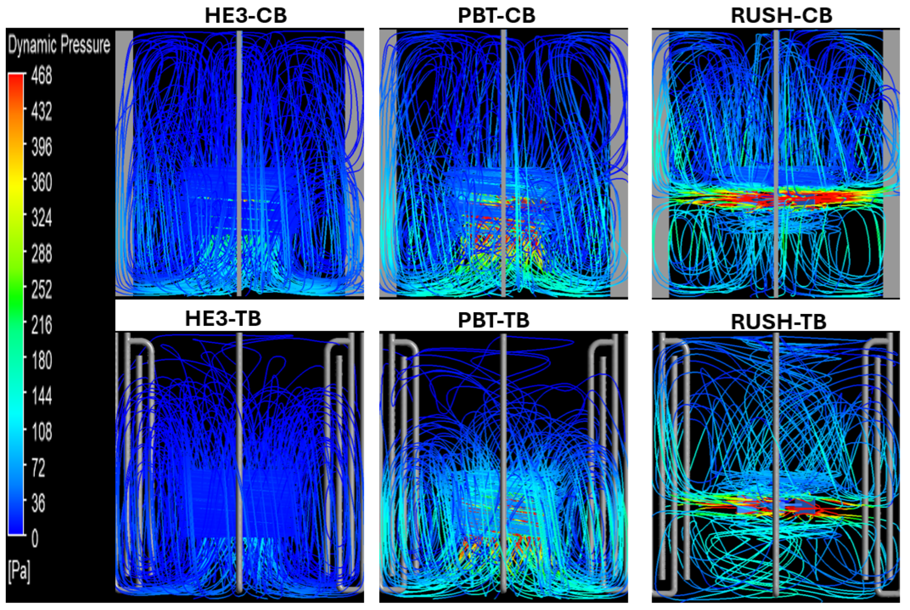
Figure 6 shows how baffle geometry greatly affects the flow patterns generated by axial impellers (HE3 and PBT). Conventional baffles create the expected single, dominant recirculation loop with impellers. In this loop, the fluid moves downward from the impeller and then upward along the baffled walls. Conventional baffles play a crucial role in this process by converting tangential momentum into axial flow and ensuring full tank circulation. However, replacing conventional baffles with tubular baffles fundamentally alters this dynamic. Two key effects are observed. First, the primary recirculation loop is confined to the lower portion of the tank and fails to reach the upper region. Second, the flow becomes more concentrated in the immediate vicinity of the impeller, leading to significantly higher localized velocities. This shift is attributed to the reduced flow-directing capability of the tubular baffles. The geometry of the tubular baffles is less effective at converting swirling flow into an axial, upward current. This weakens large-scale circulation and intensifies flow near the impeller.
Figure 6.
Streamlines for the different cases, colored by dimensionless dynamic pressure averaged at the impeller outlet.
For the HE3 and PBT impellers, it is a critical finding that the primary recirculation loop is confined to the lower portion of the tank Figure 6. This could lead to poor mixing in the upper region and create “dead zones” with longer mixing times and reduced homogeneity, particularly for solid suspensions where particles may settle [19]. The significant power savings of 64% for the HE3 impeller must be weighed against the potential for poor mixing in the upper region. This trade-off may be acceptable for processes were mixing in the upper zone is not critical or where additional design modifications are implemented, such as a second impeller or different baffle placement.
The Rushton impeller with conventional flat baffles exhibits the typical flow behavior documented in the literature [20], characterized by two dominant recirculation loops located above and below the impeller. This configuration is commonly used in processes requiring high shear to push fluid through impeller blades and break down agglomerates or bubbles in sparged systems. However, replacing flat baffles with tubular baffles significantly alters the flow pattern. The intensity of the recirculation loops within the impeller’s sweep zone decreases markedly. This attenuation primarily results from a decrease in the impeller’s suction strength, which is directly reflected in the lower NQ presented in Table 2. Despite the reduction in global flow, the local dynamic pressure in the immediate vicinity of the impeller remains largely unchanged.
3.4. Axial and Radial Local Flow Parameters
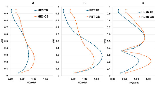
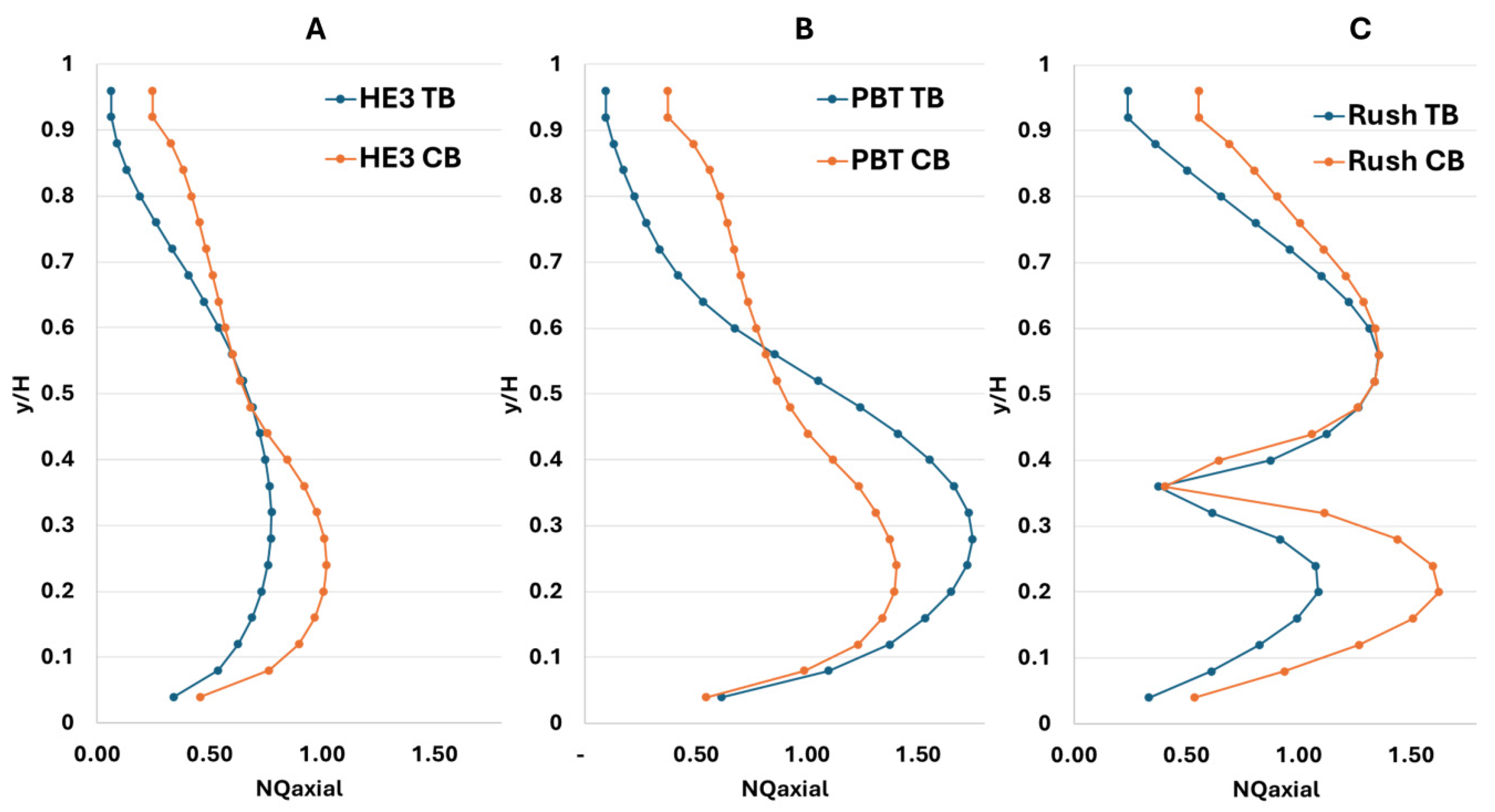
Figure 7 shows the axial flow profiles for the different cases studied. The blue line represents the results obtained with flat baffles and the orange line represents the results obtained with tubular baffles. For the HE3 impeller, the flow is similar in both configurations only in the middle region of the tank. This indicates that, as the fluid moves away from the impeller’s zone of influence, the axial velocity decreases significantly. The intersections of the axial flow profiles for the Rushton impeller (Figure 7C) suggest a change in flow dynamics. The higher axial flow in the upper region (y/H > 0.7) with tubular baffles suggests a slightly stronger top recirculation loop. Meanwhile, the lower flow near the impeller plane (y/H ≈ 0.33) correlates with the attenuated lower loop observed in Figure 6. This redistribution of axial momentum is a unique consequence of the radial impeller interacting with the less restrictive tubular baffles. It differentiates the response of the radial impeller from those of the axial impellers HE3 and PBT.
Figure 7.
Profiles of the axial pumping number for different cases obtained through CFD, (A) HE3 impeller, (B) pitched blade turbine and (C) Rushton turbine.
A higher axial circulation is observed for the PBT impeller with tubular baffles in the lower section of the tank. This finding is consistent with the flow patterns illustrated in Figure 6. However, this axial flow decays more rapidly in the upper part of the tank than in the flat baffle configuration. This attenuation is due to the lower capacity of tubular baffles to promote upward fluid momentum near the bottom of the tank, resulting in a weaker ascending jet. Conversely, the Rushton impeller with tubular baffles generates a lower axial flow throughout the tank, particularly in the lower region where the primary recirculation loop forms. The axial flow in the upper section is lower than with conventional baffles. This suppression of axial flow can be advantageous in processes such as aeration or gas dispersion. The weakened circulation increases the residence time of gas bubbles introduced at the bottom of the tank, thereby enhancing the efficiency of gas–liquid mass transfer.
Suppressing the lower axial flow loop Figure 7C increases the flow path length for bubbles introduced below the Rushton impeller. Based on the reduced axial velocity in the lower region approximately a 40% decrease at y/H = 0.2, a simple theoretical estimate suggests that the local residence time for gas bubbles in this high-shear zone could increase by a factor of 1.5 to 2. This would significantly enhance the potential for bubble breakup and gas–liquid mass transfer.
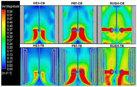
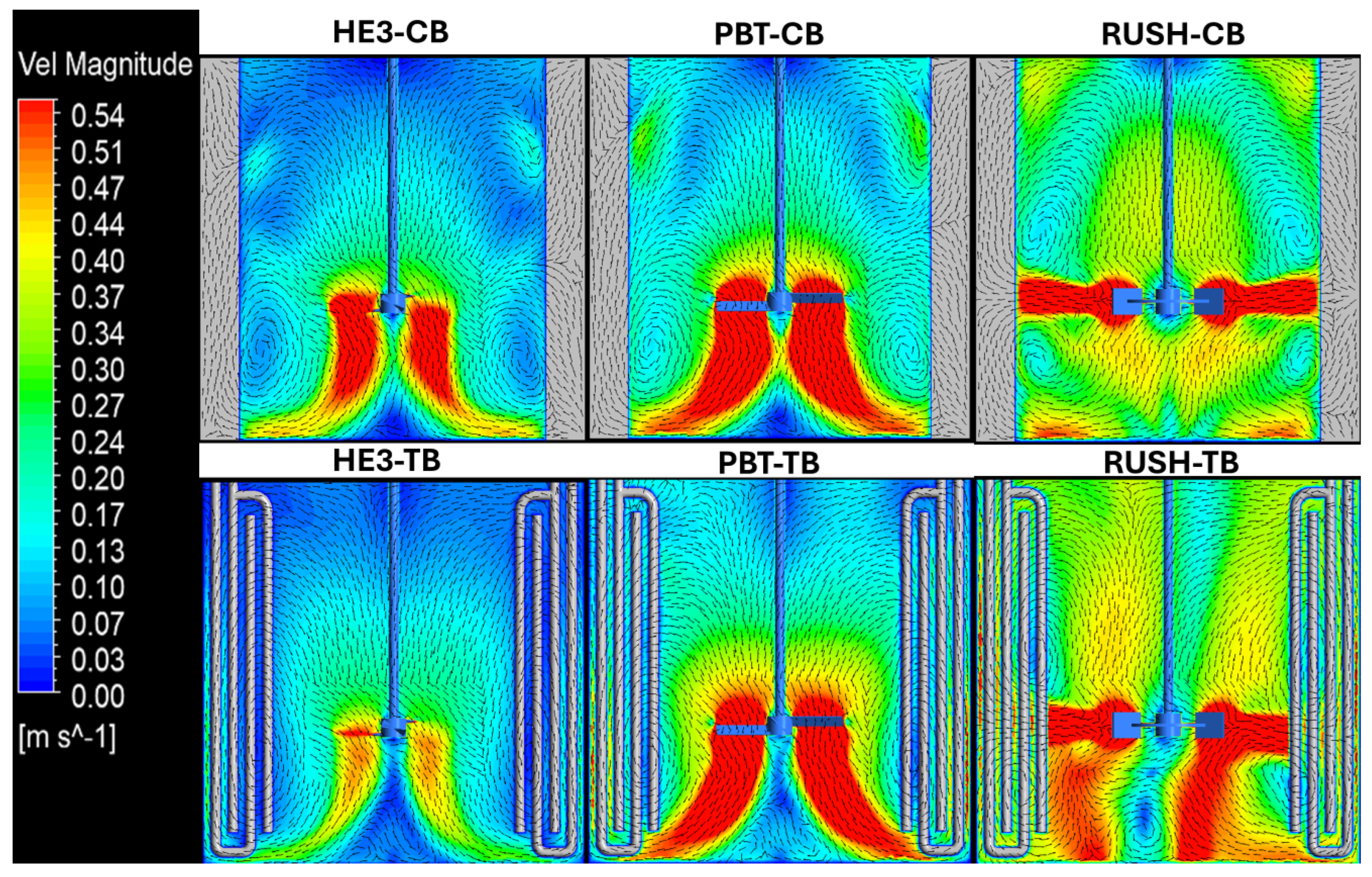
Figure 8 shows velocity contours at the midplane tank for the tubular baffle configurations and reveals that the PBT generates the highest velocity in the impeller discharge stream. Although this velocity decreases towards the top of the tank, the overall pattern is consistent with previously observed flow behavior. In contrast, the HE3 impeller exhibits a generalized reduction in velocity throughout the tank’s entire height. This is due to its high dependence on baffle interaction, which is affected by the tubular design. The Rushton impeller presents a hybrid response: it increases velocity in the lower recirculation loop while maintaining velocities in the upper loop that are comparable to those achieved with conventional flat baffles. These results suggest that tubular baffles are a viable alternative to conventional flat baffles, offering a significant reduction in power consumption while maintaining or enhancing desired flow dynamics.
Figure 8.
Planes showing the velocity magnitude for the proposed cases in this study, obtained at the tank midplane.
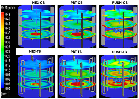
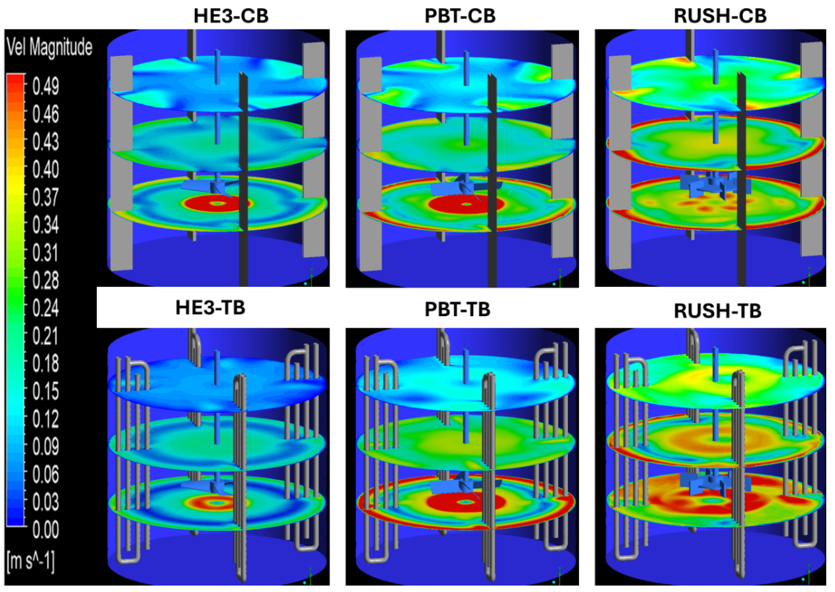
Figure 9 shows the axial velocity planes at various heights within the tank. As can be seen, tubular baffles negatively affect the performance of an HE3 impeller, reducing the velocity throughout the tank despite the high pumping efficiency. This is mainly due to the weaker lower recirculation loop since the tubular baffles do not facilitate the upward flow of fluid into the impeller suction region as effectively as the PBT impeller does.
Figure 9.
Velocity magnitude planes at different heights in the tank for the various cases presented in this study.
For the PBT impeller, an intensification of the velocity magnitude is observed in the lower region of the tank (0 < y/H < 0.7), with a reduction in velocity at the top. By contrast, the Rushton impeller has a similar velocity magnitude in the middle region of the tank (0.4 < y/H < 0.8). However, the velocity is reduced below the impeller and in the upper region.
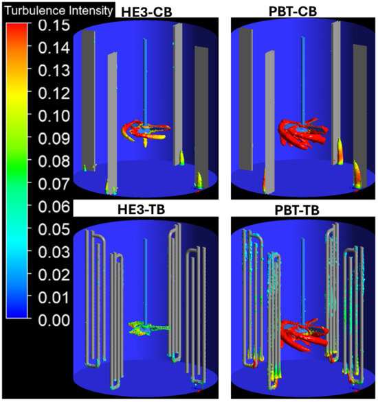
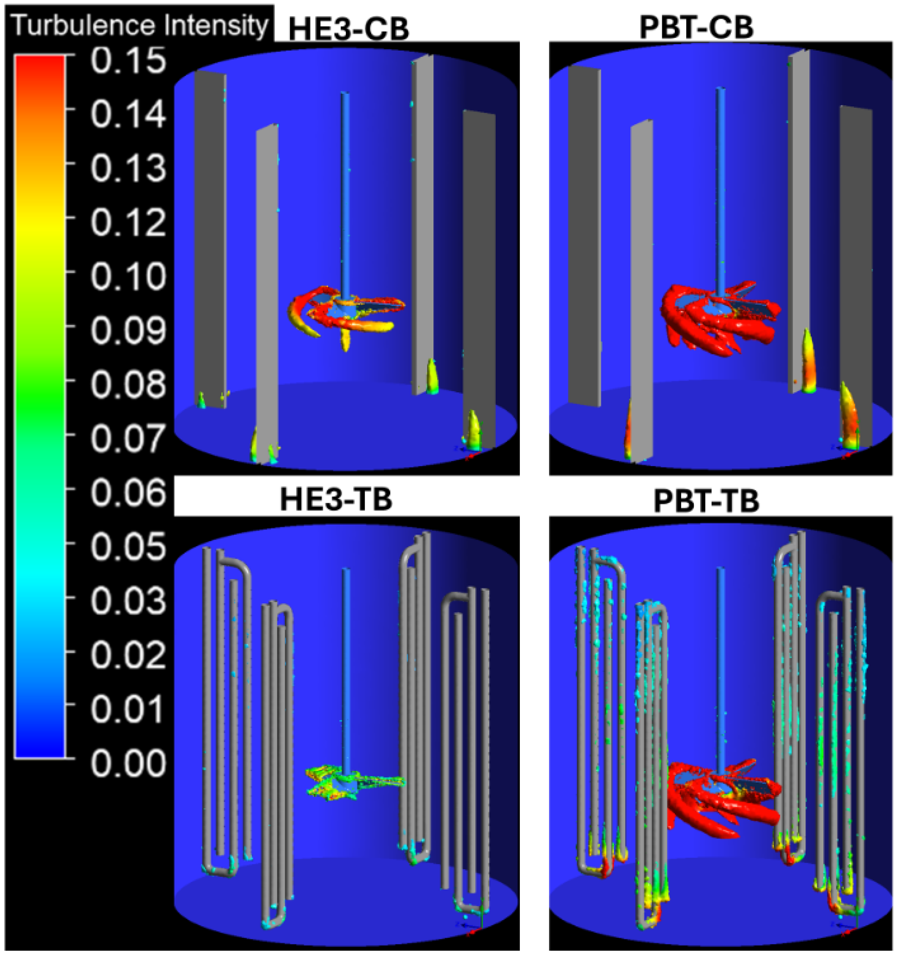
Figure 10 shows vorticity isosurfaces generated using the λ2 criterion with a value of −800 s−2. These surfaces surround the impeller and baffles. The surfaces are colored by turbulence intensity. For the HE3 impeller, vortex formation is observed within the sweep zone of the impeller, primarily induced by the passage of the blades. However, a significant reduction in the number of vortices and turbulence intensity is evident when the flat baffles are replaced with tubular ones. This attenuation is attributed to the reduced flow through the impeller, as indicated by the 30% decrease in impeller pumping number (NQ), as reported in Table 2. The HE3 impeller interacts poorly with the tubular baffles, substantially impacting its hydrodynamic performance negatively. In contrast, the vortex structures generated by the PBT impeller appear similar with both types of baffles. Key differences emerge in the baffle regions. With flat baffles, vortex formation occurs in the lower section of the tank, behind the baffles. This is due to the flow beginning its upward ascent along the tank walls. Conversely, with tubular baffles, these vortical structures form in the lower section and at various heights throughout the tank. They are generated by the flow passing between the tubes of the baffle assembly. The turbulence intensity associated with these structures is low, ranging from 0.03 to 0.05.
Figure 10.
Vorticity isosurfaces a −800 s−2 in the impeller region are colored by turbulence intensity for axial impellers.
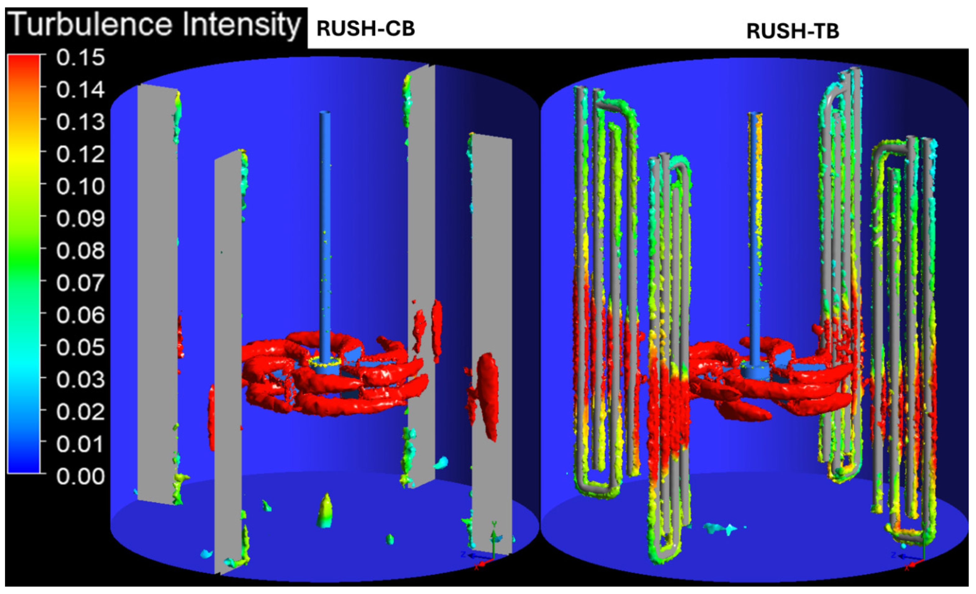
Figure 11 shows the vorticity isosurfaces of the Rushton impeller, which exhibits distinct behavioral changes when the baffle type changes. The first notable difference occurs in the impeller’s sweep zone beneath the disk, where a significant reduction in the vortex wake is observed. This attenuation is attributed to the decrease in axial flow shown in Figure 6. In contrast, the flow patterns above the impeller disk are similar to those of the flat baffle configuration because the axial flow characteristics in this upper zone are comparable for both cases. The second major difference is evident in the baffle region. With flat baffles, vortices predominantly form in the impeller’s immediate discharge stream. However, with tubular baffles, high-intensity vortices (with values exceeding 0.15) are generated in the impeller discharge as well. Furthermore, these turbulent structures propagate along the entire height of the baffles, albeit with lower intensity (averaging around 0.1).
Figure 11.
Vorticity isosurfaces a −800 s−2 in the impeller region are colored by turbulence intensity for Rushton impellers.
The presence of these widespread vortices is advantageous for applications where the baffles serve a dual purpose. For example, when the baffles function as tubular heat exchangers, the impinging flow reduces the thermal boundary layer, significantly enhancing heat transfer efficiency. Similarly, in aerated bioreactors, this distributed turbulence promotes bubble breakup, resulting in a smaller mean bubble size. The flow directed toward the baffles fosters larger recirculation loops, increasing bubble residence time within the tank and improving gas–liquid mass transfer.
The Rushton impeller with tubular baffles induces a hydrodynamic behavior characterized by distributed, high intensity turbulence and directed flow towards the baffle surface Figure 11. This behavior has direct and promising implications for process intensification. This flow pattern is highly desirable when the baffles are designed to serve a dual role, such as acting as heat exchangers.
A significant engineering challenge in conventional shell-and-tube heat exchangers is effectively redirecting the shell-side flow toward the tube bundle to enhance heat transfer while minimizing the associated pressure drop. Computational studies have demonstrated that strategic baffle design is crucial for this purpose. For example, [21] used CFD analysis to show that redirecting the flow towards the tubes via baffles directly increases the local heat transfer coefficient. Similarly, studies on continuous flow electric heaters emphasize that CFD is an essential tool for determining heat transfer coefficients in complex geometries where flow must be guided toward heated surfaces [22].
Our results suggest that the tubular baffle configuration paired with a radial impeller, such as a Rushton turbine, inherently performs the function of redirecting the flow. The impeller actively drives fluid into the tubular baffle, creating a flow that reduces the thermal boundary layer. The inherent geometry of the tubular baffles, with gaps between the tubes, likely presents lower flow resistance than the contorted paths of traditional segmental baffle heat exchangers. This characteristic mitigates the common tradeoff between enhancing heat transfer and power consumption. Thus, an agitated tank with tubular baffles is not just a mixing vessel; it can also be conceptualized as a stirred-tank heat exchanger, in which mixing and heat transfer are enhanced synergistically. Future work should quantify the heat transfer performance and pressure drop of this novel configuration to validate its advantages over conventional designs.
4. Conclusions
This study shows that replacing conventional baffles with tubular ones in stirred tanks significantly impacts energy consumption and flow dynamics. The effects vary considerably depending on the type of impeller. The most notable finding is the substantial reduction in energy consumption across all tested impellers. Power numbers decreased by 64%, 13%, and 23% for the HE3, PBT, and Rushton impellers, respectively. This reduction is attributed to the lower flow resistance offered by the tubular baffles, which allow fluid to pass more freely through the gaps between the deflector bars.
The HE3 impeller achieved the highest mixing efficiency when used with tubular baffles, nearly doubling efficiency. This was due to a significant reduction in power that offset the decreased pumping capacity. However, this configuration resulted in decreased overall axial flow and turbulence, which confined the recirculation loop to the lower part of the tank.
The PBT impeller had a balanced profile. It increased the pumping number by 10% and showed a 30% improvement in mixing efficiency. Flow patterns intensified in the lower tank region, making the PBT impeller ideal for processes requiring strong bottom circulation, such as those involving suspended solids. However, performance declined near the surface.
The Rushton impeller was the most robust candidate for direct baffle replacement. Although mixing efficiency is not an optimal performance metric for this predominantly radial flow design, the impeller preserved flow dynamics comparable to those of the conventional configuration, especially in the upper circulation loop. At the same time, the impeller achieved a 23% reduction in power consumption and a 25% decrease in energy dissipation. These characteristics make it especially suitable for applications such as gas dispersion or aeration, where sustained turbulence and increased gas residence time are critical. Additionally, this flow-redirection system is a promising platform for integrated stirred-tank heat exchangers because it can overcome the limitations associated with power input.
Author Contributions
Conceptualization, J.E.L.H. and J.A.Y.V.; methodology, J.E.L.H., S.A.M.D. and J.A.Y.V.; validation, J.E.L.H., S.A.M.D., A.A.G. and J.A.Y.V.; formal analysis, S.A.M.D.; investigation, J.E.L.H., S.A.M.D. and J.A.Y.V.; data curation, G.R.R.; writing—original draft preparation, J.E.L.H.; writing—review and editing, J.E.L.H., S.A.M.D., A.A.G. and J.A.Y.V.; visualization, G.R.R.; supervision, S.A.M.D.; project administration, S.A.M.D. and J.A.Y.V. All authors have read and agreed to the published version of the manuscript.
Funding
This research received no external funding.
Data Availability Statement
The original contributions presented in this study are included in the article. Further inquiries can be directed to the corresponding author.
Acknowledgments
The authors are grateful for the support of the Secretaría de Ciencia, Humanidades, Tecnología e Innovación (SECIHTI) for funding this research through the National (Traditional) Scholarship Program 2022-2. They also thank their advisors for their guidance, direction, and patience throughout the development of this work.
Conflicts of Interest
The authors declare no conflict of interest.
Nomenclature
| D | Impeller diameter (m) |
| H | Tank height (m) |
| N | Impeller rotational speed (s−1) |
| NP | Power number, P/(ρN3D5) (-) |
| NQ | Pumping number, Q/(ND3) (-) |
| NQax | Axial pumping number (-) |
| P | Power input (W) |
| PBT | Pitched-Blade Turbine |
| Q | Impeller pumping capacity (m3 s−1) |
| Qax | Axial flow rate (m3 s−1) |
| Re | Reynolds number, ρND2/μ (-) |
| RT | Rushton Turbine |
| T | Tank diameter (m) |
| U | Mean velocity (m s−1) |
| VT | Tank volume (m3) |
| Greek Symbols | |
| ε | Turbulent kinetic energy dissipation rate (m2 s−3) |
| ετ | Volume-averaged dissipation rate (W kg−1) |
| ηE | Pumping efficiency, N_Q/N_P (-) |
| μ | Dynamic viscosity (Pa·s) |
| μt | Turbulent viscosity (Pa·s) |
| ρ | Density (kg m−3) |
| τ | Torque (N·m) |
References
- Paul, E.L.; Atiemo-Obeng, V.A.; Kresta, S.M. (Eds.) Handbook of Industrial Mixing: Science and Practice; John Wiley & Sons: Hoboken, NJ, USA, 2004. [Google Scholar]
- Tang, L.; Ji, Y.; Zhang, X.Y.; Liu, J.; Ren, L. Stirring tank design for powder-mixed EDM SiC/Al and solid-liquid suspension uniformity research. Int. J. Adv. Manuf. Technol. 2020, 107, 2007–2021. [Google Scholar] [CrossRef] [Scilit]
- Prakash, B.; Bhatelia, T.; Wadnerkar, D.; Shah, M.T.; Pareek, V.K.; Utikar, R.P. Vortex shape and gas-liquid hydrodynamics in unbaffled stirred tank. Can. J. Chem. Eng. 2019, 97, 1913–1920. [Google Scholar] [CrossRef] [Scilit]
- Gu, D.; Liu, Z.; Qiu, F.; Li, J.; Tao, C.; Wang, Y. Design of impeller blades for efficient homogeneity of solid-liquid suspension in a stirred tank reactor. Adv. Powder Technol. 2017, 28, 2514–2523. [Google Scholar] [CrossRef] [Scilit]
- Salho, A.K.; Hamzah, D.A. A Review of Stirred Tank Dynamics: Power Consumption, Mixing Time and Impeller Geometry. Int. Inf. Eng. Technol. Assoc. 2024, 42, 1081–1092. [Google Scholar] [CrossRef] [Scilit]
- Ghotli, R.A.; Shafeeyan, M.S.; Abbasi, M.R.; Raman, A.A.A.; Ibrahim, S. Macromixing study for various designs of impellers in a stirred vessel. Chem. Eng. Process.-Process Intensif. 2020, 148, 107794. [Google Scholar] [CrossRef] [Scilit]
- Nabeshima, M.; Matsumoto, H.; Hamzah, A.B.; Yoshikawa, S.; Ookawara, S. Analysis of Dynamic Behavior of Gas Bubbles and Solid Particles in an Oscillatory Baffled Reactor and Its Application to Design of Hydrogenation Process. Chem. Eng. Trans. 2022, 94, 967–972. [Google Scholar] [CrossRef]
- Mollinedo, H.; Mendoza-Escamilla, V.X.; Rivadeneyra-Romero, G.; Gonzalez-Neria, I.; Yañez-Varela, J.A.; Alonzo-Garcia, A.; Lugo-Hinojosa, J.; Martínez-Delgadillo, S.A. Power Consumption and Energy Dissipation Rate Reduction in Agitated Tanks by Control Rods Attached to a Pitched Blade Impeller. Ind. Eng. Chem. Res. 2022, 61, 11898–11907. [Google Scholar] [CrossRef] [Scilit]
- Zhou, S.; Yang, Q.; Lu, L.; Xia, D.; Zhang, W.; Yan, H. CFD Analysis of Sine Baffles on Flow Mixing and Power Consumption in Stirred Tank. Appl. Sci. 2022, 12, 5743. [Google Scholar] [CrossRef] [Scilit]
- Pukkella, A.K.; Vysyaraju, R.; Tammishetti, V.; Rai, B.; Subramanian, S. Improved mixing of solid suspensions in stirred tanks with interface baffles: CFD simulation and experimental validation. Chem. Eng. J. 2019, 358, 621–633. [Google Scholar] [CrossRef] [Scilit]
- Dostál, M.; Petera, K.; Rieger, F. Measurement of Heat Transfer Coefficients in an Agitated Vessel with Tube Baffles. Acta Polytech. 2010, 50, 46–57. [Google Scholar] [CrossRef] [Scilit] [PubMed]
- Segawa, Y.; Tonomura, O.; Sotowa, K.I. CFD-based Design of Multi-tube Heat Exchange Type Compact Reactor. Chem. Eng. Trans. 2023, 99, 529–534. [Google Scholar] [CrossRef]
- Mendoza-Escamilla, V.X.; Alonzo-García, A.; Mollinedo, H.R.; González-Neria, I.; Yáñez-Varela, J.A.; Martinez-Delgadillo, S.A. Assessment of k–ε models using tetrahedral grids to describe the turbulent flow field of a PBT impeller and validation through the PIV technique. Chin. J. Chem. Eng. 2018, 26, 942–956. [Google Scholar] [CrossRef] [Scilit]
- Murthy, B.N.; Joshi, J.B. Assessment of standard k-ε, RSM and LES turbulence models in a baffled stirred vesselagitated by various impeller designs. Chem. Eng. Sci. 2008, 63, 5468–5495. [Google Scholar] [CrossRef] [Scilit]
- De La Concha-Gómez, A.D.; Ramírez-Muñoz, J.; Márquez-Baños, V.E.; Haro, C.; Alonso-Gómez, A.R. Effect of the rotating reference frame size for simulating a mixing straight-blade impeller in a baffled stirred tank. Rev. Mex. Ing. Quim. 2019, 18, 1143–1160. [Google Scholar] [CrossRef] [Scilit]
- Patil, H.; Patel, A.K.; Pant, H.J.; Vinod, A.V. CFD simulation model for mixing tank using multiple reference frame (MRF) impeller rotation. ISH J. Hydraul. Eng. 2021, 27, 200–209. [Google Scholar] [CrossRef] [Scilit]
- Sheng, J.; Meng, H.; Fox, R.O. A large eddy PIV method for turbulence dissipation rate estimation. Chem. Eng. Sci. 2000, 55, 4423–4434. [Google Scholar] [CrossRef] [Scilit]
- Joshi, J.B.; Nere, N.K.; Rane, C.V.; Murthy, B.N.; Mathpati, C.S.; Patwardhan, A.W.; Ranade, V.V. CFD simulation of stirred tanks: Comparison of turbulence models (Part II: Axial flow impellers, multiple impellers and multiphase dispersions). Can. J. Chem. Eng. 2012, 89, 754–816. [Google Scholar] [CrossRef] [Scilit]
- Zhang, W.; Gao, Z.; Yang, Q.; Zhou, S.; Xia, D. Study of Novel Punched-Bionic Impellers for High Efficiency and Homogeneity in PCM Mixing and Other Solid-Liquid Stirs. Appl. Sci. 2021, 11, 9883. [Google Scholar] [CrossRef] [Scilit]
- Tamburini, A.; Brucato, A.; Ciofalo, M.; Gagliano, G.; Micale, G.; Scargiali, F. CFD simulations of early- to fully-turbulent conditions in unbaffled and baffled vessels stirred by a Rushton turbine. Chem. Eng. Res. Des. 2021, 171, 36–47. [Google Scholar] [CrossRef] [Scilit]
- Ozden, E.; Tari, I. Shell side CFD analysis of a small shell-and-tube heat exchanger. Energy Convers. Manag. 2010, 51, 1004–1014. [Google Scholar] [CrossRef] [Scilit]
- Márquez-Baños, V.E.; Valencia-López, J.J.; García-Aranda, O.; Heard, C. Determinación computacional del coeficiente de transferencia de calor en calentadores eléctricos de flujo continuo, mediante dinámica de fluidos computacional. Inf. Tecnol. 2016, 27, 151–162. [Google Scholar] [CrossRef] [Scilit]

Disclaimer/Publisher’s Note: The statements, opinions and data contained in all publications are solely those of the individual author(s) and contributor(s) and not of MDPI and/or the editor(s). MDPI and/or the editor(s) disclaim responsibility for any injury to people or property resulting from any ideas, methods, instructions or products referred to in the content. |
© 2026 by the authors. Licensee MDPI, Basel, Switzerland. This article is an open access article distributed under the terms and conditions of the Creative Commons Attribution (CC BY) license.