


Abstract
JPEG images are widely used in multimedia transmission, such as on social media platforms, owing to their efficiency for reducing storage and transmission requirements. However, because such images may contain sensitive information, encryption is essential to ensure data privacy. Traditional image encryption schemes face challenges when applied to JPEG images, as maintaining compatibility with the JPEG structure and managing the effects of lossy compression can distort encrypted data. Existing JPEG-compatible encryption methods, such as Encryption-then-Compression (EtC) and Compression-then-Encryption (CtE), typically employ a single encryption stage, either before or after compression, and often involve trade-offs between security, storage efficiency, and visual quality. In this work, an Encryption–Compression–Encryption algorithm is presented that preserves full JPEG compatibility while combining the advantages of both EtC and CtE schemes. In the proposed method, pixel-block encryption is first applied prior to JPEG compression, followed by selective coefficient encryption after compression, in which the quantized DC coefficient differences are permuted. Experimental results indicate that the second encryption stage enhances the entropy achieved in the first stage, with both stages complementing each other in terms of resistance to attacks. The addition of this second layer does not significantly impact storage efficiency or the visual quality of the decompressed image; however, it introduces a moderate increase in computational time due to the two-stage encryption process.
MSC:
68P25
1. Introduction
Given the current volume of digital image transactions over the internet, image compression has become necessary for reducing transmission times and storage requirements [1]. JPEG (Joint Photographic Experts Group) is the most widely used format for such purposes [2], making it especially suitable for platforms like social media, where efficient image handling is critical. Another relevant context is the Internet of Things, where images generated by connected devices must be processed and stored efficiently [3].
However, digital images often contain sensitive information, making them vulnerable when transmitted over untrusted channels such as the Internet [4]. Cryptography provides a solution to safeguard the privacy of such content through encryption, using a wide range of technologies and methods, such as neural networks [5]. According to the encryption taxonomy proposed by Ahmad et al. [6], algorithms based on number theory and chaos theory (e.g., [7,8]) are among the most secure, as they are capable of concealing all the information contained in the image. Another category is perceptual encryption, which aims to obscure only the human-perceivable information of the image. In this category, pixel-level operations generally render the image incompressible, whereas block-based approaches maintain compressibility by performing encryption on pixel blocks. Ahmad et al. [6] conclude that this represents a trade-off between security and the ability to maintain compatibility with standard image storage formats.
On the other hand, while JPEG compression effectively addresses the need for reduced transmission time and storage space, it does not inherently address privacy concerns. Consequently, there is a need for encryption methods that are compatible with JPEG’s lossy compression [9], ensuring data security without compromising the usability of the JPEG file format.
Generally, image encryption schemes that account for compression can be categorized into three types [10]:
- 1.
- Encryption-then-Compression (EtC), where encryption is performed before compression.
- 2.
- Compression-then-Encryption (CtE), where the compression precedes encryption.
- 3.
- Simultaneous Compression and Encryption (SCE), where both processes are integrated into a unified framework.
SCE algorithms require specialized decoding mechanisms because the standard compression steps are altered to incorporate encryption, which differs from conventional JPEG processes. For instance, Li and Lo modified the standard Discrete Cosine Transform (DCT) by introducing new orthogonal transforms [11], an area that continues to be actively explored [12]. Another example is the work of Wang and Lo, who used a deep learning-based compression network that requires this approach for decoding [13]. However, the present work does not consider such approaches, as it aims to remain fully compatible with the standard JPEG compression and decompression.
In contrast, the present work does not adopt such approaches, as it aims to remain fully compatible with the standard JPEG compression and decompression process. Zhang et al. proposed a JPEG-compatible encryption scheme that simultaneously performs compression and encryption across three stages of image processing: DCT transformation, quantization, and entropy encoding [14]. However, in this work, the primary objective is to preserve the original JPEG compression process, allowing the use of existing, time-optimized JPEG implementations while avoiding numerical overflows during compression. Therefore, the proposed method applies encryption techniques from both the EtC and CtE types, integrating their key features while maintaining full compatibility with the JPEG file format.
However, some EtC algorithms are tailored to non-standard compressed formats. For instance, Singh et al. employed wavelet-based compression [15] for ensuring the subsequent decryption. However, in EtC scheme, reconstruction must be performed on encrypted, lossy data, complicating the process. This necessitates encryption algorithms that account for such complexity, but it leads to consider more steps for image decryption. For example, Jian et al. analyzed relationships between compressed images and discarded pixels to enable accurate reconstruction [16].
In the context of JPEG-specific EtC approaches, Kurihara et al. introduced a perceptual encryption method that allows the encrypted image to retain a visually appearance through four block-based encryption steps [17]. However, their work does not include an analysis of security metrics such as entropy, correlation, resistance to differential attacks, etc. There are not quantitative evaluations of encryption, as is done in this work. Subsequently, Chuman et al. proposed a block-scrambling-based encryption scheme that supports JPEG compression with grayscale encryption of originally images to mitigate color compression issues and demonstrated its applicability on social media platforms [18]. However, this approach requires modifying the image dimensions from to , resulting in grayscale encrypted content. In addition, no security measures such as entropy were reported to assess the benefits of this modification. In contrast, our proposal preserves the original image dimensions and color information, avoiding limitations in applicability of grayscale encryption. Another related study was conducted by Imaizumi and Kiya, who applied encryption independently to each color channel within image blocks [19], rather than encrypting the three-color channels simultaneously as complete pixels. Encrypting channels independently reduces compression efficiency compared to the conventional block-based approach. By contrast, our proposal follows the traditional block-based strategy while introducing a second encryption layer that does not further compromise JPEG compression quality.
Overall, block-based perceptual encryption algorithms have been widely reported as suitable for JPEG image encryption. For example, Ahmad and Shin enhanced this approach by incorporating both inter- and intra-block processing [20]. Unlike our proposal, their scheme includes intra-block encryption techniques designed to improve the security of typical inter-block EtC methods. However, this additional encryption layer is also applied before compression, which affects more the compression efficiency. In contrast, our proposal introduces a second encryption layer applied after compression, which does not directly impact compression performance, aside from small variations due to JPEG markers. Finally, in several of these prior works, the improvements in security are considered only before compression, meaning that the added encryption stages directly degrade compression performance in terms of visual quality and storage. Moreover, some of these studies omit essential security metrics, limiting the completeness of their evaluation.
Regarding the CtE works, He et al. proposed a method that permutes quantized DC coefficient differences directly within the bitstream domain, in alignment with the way these values are stored [21]. In contrast, Su et al. inverted DC coefficients and then applied the differential pulse-code modulation (DPCM) step to the modified values, requiring compression time for DPCM [22]. He’s method has the advantage of preserving file size, maintaining parity with plain JPEG images. Similarly, Peng et al. introduced a scheme that permutes DC coefficients while also preserving both file size and format [23]. However, because these methods perform encryption only after compression, they additionally require encryption of the AC coefficients to prevent attacks capable of revealing image edges. By contrast, our proposal incorporates encryption prior to compression, thereby preventing the preservation of edge structures in the first place. As a result, encryption of AC coefficients and additional DPCM recompression steps are unnecessary.
In CtE schemes, storage efficiency is typically prioritized alongside security. For example, Yuan et al. proposed an approach to further reduce storage requirements after compression by removing AC coefficients and applying permutation steps [24]. While this reduces file size, it introduces additional computational cost. In comparison, our proposal considers only permutation after compression. Another example is the work by Hirose et al., who preserved JPEG file format and size by utilizing restart markers strategically inserted between Minimum Coded Units (MCUs) for encryption purposes [25]. However, this approach requires selecting specific regions of interest within the image. In contrast, our method applies encryption across the entire image.
In summary, existing proposals for JPEG image encryption presents the following characteristics. Some proposals emphasize preserving the file format and maintaining compression efficiency. However, traditional security evaluations, such as entropy and correlation, are often missing [26,27]. To address this limitation, the present work incorporates not only compression performance and visual quality assessments but also entropy and correlation metrics. Moreover, most prior studies implement encryption at a single stage. Exploring encryption across multiple stages offers the potential to combine the strengths of both approaches in terms of security, storage efficiency, and visual quality. Introducing multiple encryption phases can also enhance resistance against targeted attacks, whether they occur before or after compression [28,29]. A central challenge, however, lies in ensuring compatibility between encryption schemes applied at different stages. Many existing methods assume encryption is performed on a plain image, or that compression is the final step before storage the image, which complicates their integration into multi-stage encryption.
Motivation: Most existing encryption algorithms designed to support compression apply encryption at a single stage (either before, during, or after compression). However, to achieve enhanced security it may be beneficial to combine encryption techniques across multiple stages. A primary challenge in doing so lies in preserving compatibility with the JPEG format, which imposes specific structural and encoding constraints. The main objective of this work is to design and implement an encryption algorithm that integrates both encryption-then-compression and compression-then-encryption (CtE) techniques, while maintaining full compliance with the JPEG file format. This integration aims to enhance security, preserve visual quality, and sustain efficient storage through JPEG lossy compression.
Contribution: We propose an encryption algorithm that maintains JPEG file format compatibility while applying encryption both before and after compression, forming a structure encryption–compression–encryption. This dual encryption-stage approach combines the strengths of EtC and CtE techniques, resulting in improved security and efficient compression (in terms of storage, and degradation of visual quality).
The structure of this paper is organized as follows: Section 2 presents the materials and methods used in this work, including the JPEG compression algorithm, the baseline mode, and the evaluation metrics used to assess security, storage efficiency, and visual quality. Section 3 describes the decoding process of the JPEG bitstream, including the generation of Huffman codes, followed by the proposed encryption algorithm, and information about the key and permutations. The encryption is applied in two stages: prior to compression in the pixel domain and subsequently after compression in the bitstream domain. Section 4 presents the experimental results, structured according to the three types of evaluation: security, storage, and visual quality. Section 5 provides a discussion and analysis of the results, highlighting key findings and comparing them with existing approaches. Finally, Section 6 concludes the paper.
2. Materials and Methods
This section provides an overview of the JPEG compression, from the image pixels to the compressed JPEG file. The section also includes the description of the baseline JPEG mode, as it is the setting mode of the proposed method. The section also outlines the metrics used to evaluate performance: entropy, linear correlation, and the differential attack measures for security assessment, bits per pixel (bpp) for storage efficiency, peak signal-to-noise ratio (PSNR), and the structural similarity index for visual quality.
2.1. JPEG Overview
The process of generating a JPEG bitstream involves distinct steps, each critical to the image compression procedure. Below is a concise explanation (with an example) of the key steps leading to the creation of a JPEG image.
2.1.1. Color Space Transformation
Any plain image can be represented in a three-dimensional space, known as the RGB color space, defined by the three primary colors: red (R), green (G), and blue (B), ranging from 0 to 255. However, JPEG converts the image from the RGB color space to the YCbCr color space using a system of three equations, as defined in Equation (1),
where:
- Y: Luminance channel.
- Cb: Blue chrominance channel.
- Cr: Red chrominance channel.
The purpose of this step is to separate the image into its luminance and chrominance components, ranged from 0 to 255. Since the human visual system is more sensitive to variations in brightness (luminance) than to color (chrominance), this separation allows for more intensive compression of the chrominance components, compared to the luminance component.
2.1.2. Subsampling and Blocks Division
In this stage, the chrominance components undergo subsampling, while both luminance and subsampled chrominance components are divided into blocks of 8 × 8 elements, as the subsequent processing stages operate exclusively on 8 × 8 blocks. On the other hand, the subsampling factors indicate the way of subsampling. The values used in this work are:
- 1.
- Luminance: A vertical sampling factor of 2 and a horizontal sampling factor of 2.
- 2.
- Chrominance (Cb and Cr): A vertical sampling factor of 1 and a horizontal sampling factor of 1.
The vertical sampling factor of one indicates that for every chrominance block read in this direction, two luminance blocks are vertical processed, as the vertical subsampling factor for luminance is set to two. Similarly, this proportion applies in the horizontal direction. As a result, for every 16 × 16-pixel area (256 pixels) of the image, four 8 × 8 luminance blocks are processed, while only one 8 × 8 block each of blue and red chrominance is retained.
2.1.3. Discrete Cosine Transform
After dividing the image into blocks of size , each of the 64 elements in every block is subtracted by 128. This operation shifts the original intensity range of Y, Cb, Cr, from to , resulting in a new block, having entries for each channel denoted as , for . Subsequently, each modified block undergoes the Discrete Cosine Transform (DCT), as defined in Equation (2). This transformation produces a new block consisting of 64 frequency-domain coefficients, denoted as for . Each one is derived by combining all spatial-domain values weighted by the cosine basis functions.
where:
- : Represents the intensity values within an block (64 elements) of the Y, Cb, or Cr channels after subtracting 127. The elements are indexed from 0 to 7 along both the x and y directions.
- : Denotes the Discrete Cosine Transform (DCT) coefficients corresponding to the block of Y, Cb, or Cr channels, indexed from 0 to 7 in the u and v directions.
- cos: The cosine function, evaluated in radians ().
- : Normalization factors defined in Equation (3).
2.1.4. Quantization
The block resulting from the application of Equation (2), the values are divided by a fixed quantization table, denoted as , which is applied entry by entry to all blocks. This quantization step serves two primary purposes. First, it introduces zeros in the DCT coefficients with low magnitudes, which typically represent less perceptually significant information. Second, it reduces the magnitude of the remaining significant coefficients, enabling more efficient compression by requiring fewer bits for storage. The result of the division, denoted as , is computed by rounding the quotient to the nearest integer , ensuring that subsequent steps work exclusively with integers. This process is mathematically represented by Equation (4).
where:
- : The DCT coefficient located at coordinates .
- : The quantization value corresponding to the frequency position .
- : The quantized DCT coefficient obtained after dividing by and rounding to the nearest integer.
2.1.5. Zig-Zag Permutation
Next, the 64 quantized DCT coefficients are rearranged according to the Zig-Zag permutation, as illustrated in Figure 1a. The first element in this sequence is , referred to as the DC coefficient, which captures the most significant information in the block. Following Equation (2), corresponds to eight times the average of the input values . The remaining 63 coefficients are known as AC coefficients, representing the higher-frequency components of the block. To facilitate the compression, each AC coefficient is assigned an index from 1 to 63, following the order imposed by the Zig-Zag pattern. This indexing is illustrated in Figure 1c.
Figure 1.
Zig-Zag permutation. (a) Zig-Zag scanning pattern (following the arrows) used to numerate the 64 quantized DCT coefficients. (b) Identification of the DC coefficient . (c) Index assignment of AC coefficients (1–63) according to the Zig-Zag order.
2.1.6. Run-Length Encoding
This compression technique, known as Run-Length Encoding (RLE), is applied exclusively to the AC coefficients. The method involves forming pairs of values in the following manner (see Figure 2):
Figure 2.
Representation of AC coefficients from ACi to ACi+s with RLE.
- 1.
- The first value s indicates the number of consecutive zero-valued coefficients preceding a non-zero coefficient.
- 2.
- The second value t represents the non-zero AC coefficient that terminates the sequence of zeros.
Rather than storing each zero individually, this approach compactly represents long runs of zeros, which are common due to the Zig-Zag ordering introduced in the previous stage. To illustrate this process, the AC coefficients from Figure 1c are compressed using Run-Length Encoding. The resulting encoded output of Figure 1 is shown in Figure 3.
Figure 3.
Run-Length Encoding (RLE) applied to the AC coefficients obtained from the Zig-Zag ordering in Figure 1c. Each pair represents a run of zeros followed by a non-zero AC coefficient.
2.1.7. Differential Pulse Code Modulation
The encoding of DC coefficients differs from that of AC coefficients because each block contains only a single DC coefficient. In JPEG compression, DC coefficients are not stored using their original values (except for the first block’s DC coefficient, DC1). Instead, each DC coefficient is encoded as the difference ΔDCi between its value DCi and the DC value of the previous adjacent block DCi−1. This technique is known as Differential Pulse Code Modulation (DPCM). The differential value, denoted as ΔDCi−1, is computed according to Equation (5). For the first block, since no previous DC coefficient exists, its value is stored directly: .
where:
- : The DC coefficient of block i.
- : The DC coefficient of the block immediately preceding block i.
- : The differential value of with respect to the previous DC coefficient .
Thus, the value actually stored in the JPEG file is , not the original . The advantage of this method lies in the fact that adjacent blocks often have similar values, resulting in small differences. This makes typically smaller in magnitude than itself, allowing for more efficient compression. This process is illustrated in Figure 4, which shows the transformation of four DC coefficients into their corresponding differential values via DPCM.
Figure 4.
Example of Differential Pulse Code Modulation (DPCM) applied to four DC coefficients. Each DC value (except the first) is replaced by the difference with its preceding block’s DC value, reducing the magnitude of values to be stored and improving compression efficiency.
2.1.8. Huffman Symbols and Additional Bits
Huffman symbols: In this step, the AC coefficients encoded with RLE are processed as follows: the first number in each pair s, indicating the number of preceding zeros, is now represented with four bits . Subsequently, these are concatenating it with four bits that indicate the number of bits required to represent the absolute value () of the following non-zero coefficient. The result of this concatenation is known as the Huffman symbol. In summary, the Huffman symbol (HS) is always 8 bits long and represents a byte value x, as it is illustrated in Figure 5.
Figure 5.
Structure of the Huffman symbol x for AC coefficients: the first 4 bits indicate the run-length of preceding zeros, and the second 4 bits specify the number of bits required to encode the non-zero AC value. Additional bits y follow the symbol to complete the encoding of the AC coefficients.
Since DC coefficients are not preceded by sequences of zeros, the first four bits of their Huffman symbol are always set to zero. The remaining four bits, denoted as , represent the number of bits required to encode the absolute value of the differential coefficient . Thus, the complete Huffman symbol for a DC coefficient takes the form: (see Figure 6).
Figure 6.
Structure of the Huffman symbol for DC coefficients. The first four bits are fixed as zeros (indicating no preceding zeros), and the remaining four bits encode the bit-length required to represent the magnitude of the differential value . Additional bits y follow the symbol to complete the encoding of the DC coefficients.
Additional bits: To complete the AC coefficient representation, Additional Bits (AB) are appended immediately after the Huffman symbol. These bits are denoted by the value y, as shown in Figure 5. Unlike the Huffman symbol, which always consists of 8 bits, the number y of additional bits varies depending on the binary length required to encode the coefficient t. The key issue in encoding t is that AC coefficients can be either positive or negative, and binary representation must reflect the sign. To handle this, a sign convention is applied according to Equation (6). If , then . If , the convention involves computing a power of 2, the number of bits needed to represent the positive number , and ⊕ the XOR operation. The procedure for encoding the additional bits (y) for DC coefficients follows the same approach as with AC coefficients. Instead of encoding the number t, the differential value is used. This value is then assigned to the variable y.
Then, an example of encoding the block, following the application of RLE for AC coefficients (Figure 3) and DPCM for DC coefficient (Figure 4), is presented in Figure 7. The encoded output is organized sequentially, starting with the Huffman symbol x followed by its corresponding additional bits y. Together, these components represent both the DC and AC coefficients of the block.
where:
- t: Represents either the differential DC value or a nonzero AC coefficient.
- y: The binary representation used to encode the coefficient t as a positive value.
- ⊕: The bitwise XOR (exclusive OR) operation.
- : The absolute value of the coefficient t.
- : The base-2 logarithm function.
After this stage, the Huffman code is applied only to the Huffman symbols [30], the additional bits remain with the same value.
2.2. Bitstream Decoding of Coefficients
Since the second stage of the proposed encryption scheme operates on the bitstream domain, it is essential to understand how AC and DC coefficients are decoded from the JPEG bitstream. For AC components, we refer to the quantized AC coefficients, and for DC components, to the quantized values of the differential DC coefficients. The first step is decoding the Huffman symbols, which were initially encoded using Huffman codes prior to storage. In other words, the JPEG bitstream does not directly store the Huffman symbols themselves; instead, it stores their corresponding Huffman codes, which are variable-length binary sequences.
As the bitstream is composed of a continuous sequence of bits without explicit delimiters between symbols and coefficient values, the start and end of each Huffman code must be identified. Neither does the JPEG format explicitly store which Huffman code corresponds to each Huffman symbol. Rather, it provides the code-length counts which is a list with the number of Huffman codes utilized of each length from 1 to 16 bits, and a list of the Huffman symbols used. The mapping between Huffman codes and symbols is determined by the order in which the symbols appear: they are assigned in sequence to the codes of increasing length, as specified by the code-length counts. This information is sufficient to reconstruct the Huffman codes and their interpretation of Huffman symbols in the bitstream.
Throughout the JPEG bitstream, specific markers indicate the start of structural elements such as the Define Huffman Table (DHT) marker, composed of two bytes: “FFC4”, which signals the beginning of the Huffman table. This section contains all the information of the Huffman codes length and the Huffman symbols. Immediately following the marker are two additional bytes, which together define the length e (in bytes) of the Huffman table segment. This length includes the two bytes used to specify it, so the actual content of the table spans bytes (see Figure 8a). The first byte after the length field is divided in two: The first four bits (from left to right) indicate the Table ID. A value of 0 designates the Huffman table for the luminance channel, while a value of 1 designates the chrominance channel. The remaining four bits specify the table type. A value of 0 indicates a DC coefficient table, and a value of 1 indicates an AC coefficient table.
Figure 8.
Example of a Huffman Table in the JPEG Bitstream with hexadecimal format. (a) Bits distribution of the Huffman Table. (b) Example of a DHT segment in the JPEG bitstream. (c) Summary of the table length and luminance DC Huffman table. (d) Summary of the number of Huffman codes per code length and the corresponding Huffman symbols.
The next 16 bytes define the number (#) of Huffman codes for each possible code length, from 1 to 16 bits. For example, if the first byte has a value of 0, it means there are no Huffman codes of length 1. If the second byte has a value of 2, it indicates there are two Huffman codes of length 2, and so on. However, this section does not specify which Huffman codes correspond to those lengths, only how many codes exist for each length. The sum of the 16 values provides the total number w of Huffman symbols, each of which is represented by a single byte. Therefore, the next w bytes in the bitstream contain the Huffman symbols, ordered according to the lengths defined in the previous 16 bytes. All this information can be found in Figure 8a.
An example of this process is illustrated in Figure 8b, which is a part of the JPEG bitstream beginning with the DHT marker ff c4. The two subsequent bytes define the Huffman table length: 00 1d, indicating a total of 29 bytes. The following byte contains 00, where the first half indicates Table ID = 0 (luminance) and the second half (0) indicates DC coefficient table. This configuration is summarized in Figure 8c. The next 16 bytes define the number of Huffman codes for each length, and their total sum is 10. Thus, 10 Huffman symbols follow, as illustrated in Figure 8d, which summarizes the mapping between Huffman symbols and their corresponding Huffman code lengths.
It is important to note that decoding the DC and AC coefficients is in the Start of Scan (SOS) marker, which is identified by the hexadecimal value “FFDA”. In the JPEG baseline mode, there is only one scan. Immediately following the marker, the length of the scan segment is specified using two bytes. This two-bytes value does not count the two bytes used to indicate the marker (“FFDA”) or the two bytes used to specify the length itself.
The next byte indicates the number of color components involved in the scan, typically three for color images (Y, Cb, and Cr). Subsequently, for each component, two bytes follow:
- 1.
- The first byte identifies the component number (1 for Y, 2 for Cb, and 3 for Cr).
- 2.
- The second byte is divided into two parts: the upper 4 bits indicate the Huffman table used for DC coefficients, and the lower 4 bits indicate the Huffman table used for AC coefficients.
Then, the next three bytes "00 3F 00" are standard in the JPEG baseline scan header. Following this header, the compressed image data is presented, encoding the quantized DC and AC coefficients.
2.3. Huffman Code Generation Procedure
Below, we describe the process for generating Huffman codes based on the number of codes for each bit length. The 16 bytes that store this information in the JPEG bitstream compose the Number of Huffman Codes array, denoted as NHC. In this array, the entry NHC[i] indicates the number of Huffman codes of length i bits, for to 16.
- 1.
- Step 1. Initialize the variable cd to 0. This variable represents the current Huffman code being generated and is updated iteratively throughout the process.
- 2.
- Step 2. For each code length i from 1 to 16:
- (a)
- If NHC[i] = 0, this means there are no Huffman codes of length i, and the variable cd is updated as cd = cd × 2 (i.e., cd = cd << 1) to prepare for the next code length.
- (b)
- If NHC[i] > 0, then for each of the NHC[i] Huffman codes of length i (from to NHC[i]):
- i.
- Assign the current value of cd as a Huffman code of length i.
- ii.
- Increment cd by 1 (i.e., cd = cd + 1).
- (c)
- After all codes of length i have been assigned, update cd = cd × 2 to ensure the correct prefix property for the next code length.
The generated Huffman codes are assigned to the Huffman symbols in the order in which the symbols appear in the JPEG bitstream. In this way, each Huffman symbol is paired with a unique Huffman code of specified length. The resulting Huffman codes corresponding to the lengths defined in Figure 8d are illustrated in Figure 9a, where the mapping between Huffman symbols and their generated Huffman codes is shown.
Figure 9.
Huffman symbol decoding. (a) Mapping between Huffman symbols and their generated Huffman codes. (b) Example JPEG bitstream with bits sequentially presented, staring with Huffman code 01. (c) Reconstruction of the DC coefficient by interpreting the Huffman code 01 decoding the Huffman symbol 6 and its associated additional bits.
Additionally, Figure 9b presents an example bitstream as it appears in a JPEG file, where the bits are arranged sequentially. In this example, the first bit does not correspond to any valid Huffman code. Therefore, two bits are considered. Referring to Figure 9a, this two-bit sequence matches the second Huffman code, which maps to the second stored Huffman symbol (with a value of 6 in this case).
Decoding involves replacing each Huffman code in the bitstream with its corresponding Huffman symbol. For DC coefficients, the decoded symbol indicates how many additional bits should be read. These additional bits follow immediately after the Huffman code and represent the actual DC value. This decoding process is illustrated in Figure 9c.
2.4. JPEG Baseline Mode
The JPEG (Joint Photographic Experts Group) standard, developed by a committee of the same name, defines two main types of image compression: lossless and lossy [31]. For the lossy compression scheme, the baseline mode refers to the simplest and most widely supported variant of JPEGs. It is characterized by a straightforward encoding and decoding process and is particularly favored for its balance between compression efficiency and computational simplicity. Its key features are outlined below [32,33]:
- Processes the image in non-overlapping blocks of size pixels.
- Employs a sequential rather than progressive encoding approach, meaning the image is encoded in a single scan from left to right and top to bottom.
- Uses the Type-II Discrete Cosine Transform, as defined in Equation (2), instead of wavelet-based prediction techniques.
- Relies on Huffman coding for encoding Huffman symbols, rather than arithmetic coding.
- Utilizes default Huffman tables where the Huffman codes are reconstructed by the decoder, as Huffman codes are not included within the compressed image file.
- Supports compression in various color spaces, with better performance in those that separate chromatic (color) and achromatic (luminance) components (e.g., YCbCr).
- Employs at most two sets of Huffman tables: one for the luminance (achromatic) component and another for the chrominance (chromatic) components. Each set includes one table for DC coefficients and another for AC coefficients.
- Marks the beginning of a baseline-compressed frame with the Start of Frame (SOF0) marker, which has a hexadecimal value of FFC0.
2.5. Information Entropy
Information entropy, denoted as H and defined by Equation (7), quantifies the degree of randomness or unpredictability within a sequence of bits. In the context of cryptography, it is widely used to assess the security of encrypted data [34]. In this study, entropy is calculated for each color channel (red, green, and blue) of the compressed and encrypted images independently.
The function represents the base-2 logarithm. An ideal encrypted image should exhibit an entropy value close to the maximum of 8.0, which indicates a highly random distribution of pixel values and, therefore, a stronger resistance to statistical attacks.
where:
- x: The intensity level of a pixel ranging from 0 to 255.
- : The probability that a pixel in the encrypted and compressed image takes the value x.
2.6. Correlation Coefficient
The correlation coefficient r is a statistical measure (from −1 to 1) used to evaluate the linear dependency between adjacent pixels in an image. In encryption analysis, lower correlation values are desirable, as they suggest a greater disruption of spatial relationships, thereby indicating stronger encryption [35]. A correlation value close to zero indicates minimal linear relationship, which is ideal for ensuring effective image encryption. It is calculated according to Equation (8) and applied separately to each color channel (red, green, blue).
where:
- w: The number pixels randomly selected from the image.
- : The value of pixel i.
- : The value of the adjacent neighbor pixel of pixel i.
- : The mean of the sampled pixels.
- : The mean of the corresponding neighbor pixels.
2.7. Number of Pixel Change Rate and Unified Average Changing Intensity
The robustness of the proposed encryption scheme against differential attacks is evaluated using two metrics: the Number of Pixel Change Rate (NPCR) and the Unified Average Changing Intensity (UACI). Both metrics measure the sensitivity of the encryption algorithm to variations in the input image, specifically analyzing how a one-pixel change in the plain image affects the resulting encrypted image, at each position [36].
In this evaluation, two plain images of identical dimensions , differing only in the value of a single pixel, while all other pixel values are equal, where:
- C is the encrypted image of the initial plain image.
- is the encrypted image of the image that differs in one pixel of the plain image.
- p is the number of pixel rows.
- q is the number of pixel columns.
The NPCR metric measures the percentage of pixels whose values differ between two encrypted images and is defined as Equation (9):
where:
- C: The encrypted image of the initial plain image.
- : The encrypted image of the image that differs in one pixel of the plain image.
- p: The number of pixel rows.
- q: The number of pixel columns.
- : The variable defined in Equation (10).
On the other hand, UACI measures the average intensity difference between the original encrypted image C and the encrypted image using Equation (11):
A desirable NPCR value is 99.5693, and for UACI a value within the range of .
2.8. Peak Signal-to-Noise Ratio
To assess the visual quality of images before and after lossy compression, the Peak Signal-to-Noise Ratio (PSNR) is employed, as shown in Equation (12).
where:
- : The value of pixel of the original uncompressed image I.
- : The value of pixel of the decompressed image K.
This metric is derived from the Mean Squared Error (MSE) between the corresponding pixel intensities of the two images. The MSE quantifies the average of the squared differences between corresponding pixel values in I and K [37]. This value constitutes the denominator in the PSNR expression. The numerator reflects the dynamic range of pixel values in the image, which for 8-bit images is 255. The PSNR is then computed as the logarithm (base 10) of the ratio between the dynamic range and the MSE, scaled by a factor of 20. A higher PSNR value indicates better preservation of image quality after compression. In this work, PSNR is computed separately for each color channel (red, green, and blue). In addition, the PSNR is utilized to measure the encryption quality [36], where the lower PSNR value the better quality of encryption.
2.9. Bits per Pixel
Bits per pixel (bpp) represents the average number of bits required to store a single pixel in an image. It is calculated by dividing the total number of bits used to store the image by the total number of pixels, as shown in Equation (13). This metric is particularly useful for evaluating the efficiency of compression algorithms by comparing the storage requirements of compressed images with those of uncompressed formats. For instance, a standard uncompressed 24-bit image uses 24 bits per pixel. Alternative metrics such as bytes per pixel or bits per channel can be derived from the bpp value if needed [38].
3. Methodology
This section presents the proposed scheme, named ECEA (Encryption–Compression–Encryption Algorithm), which performs encryption both before and after JPEG compression while maintaining format compatibility. In other words, the output remains a valid JPEG file that can be recognized and displayed by any standard image viewer. The proposed method is designed for JPEG images in baseline mode, as its features were described in Section 2.4. The ECEA process consists of two encryption stages: pre-compression encryption in the pixel domain and post-compression encryption in the bitstream domain. Both encryption stages are applied in a way that preserves the JPEG format structure, ensuring compatibility and visualizability of the encrypted output in a JPEG image viewer.
3.1. Proposal
Given an input plain image of size (i.e., p rows and q columns), the ECEA procedure follows these steps:
Pre-compression Encryption:
The first encryption stage operates on the raw pixel data before compression. The image is divided into non-overlapping blocks of size , where n is a multiple of 8 to align with the block size used in JPEG compression. Each block undergoes the following operations:
- Step 2: Negative–Positive Transformation. Perform the negative–positive transformation on each block, as Equation (14) indicates.where:
- ‐
- : The pixel value at position of the plain image of 24 bits with three color channels.
- ‐
- : The encrypted value of pixel .
- ‐
- R: A Bernoulli random-variable.
If selected, transform each pixel in the block as , otherwise (see Figure 10c). Therefore, pixel values remain within valid ranges but are altered for encryption - Step 3: Compression. The resulting image, now encrypted at the pixel level, is then compressed using standard baseline JPEG compression.
Figure 10.
Illustration of the first two steps of the proposed ECEA scheme. (a) Division of the image into non-overlapping color-pixel blocks of size . (b) Block permutation to shuffle spatial positions. (c) Application of the negative–positive transformation to individual blocks.
Post-Compression Encryption
Different to other proposals there is a second encryption stage, where the post-compression encryption is done over an encrypted image. It is done directly on the JPEG bitstream, where pixels have already been transformed into Huffman-encoded DC and AC coefficients. In this part it is assumed that it is known the value of each Huffman code for each Huffman symbol following the procedure described in Section 2.2.
- Step 4: Decode DC coefficient. Identify the presence of a Huffman code within the JPEG bitstream and decode it to retrieve the corresponding Huffman symbol (see Figure 11a(1)). Based on the value of the decoded Huffman symbol, determine the appropriate number of bits required to extract the associated Additional Bits (see Figure 11a(2)). With the extracted Additional Bits, reconstruct the coefficient (see Figure 11a(3)).
- Step 5: Decode DC coefficients. Repeat the step 4 for each DC coefficient, and identify them with their own sign (see example of Figure 11b).
- Step 6: Grouping. Consecutive DC coefficients with the same sign are placed in the same group Gi (see example of Figure 11c). In each group, the DC coefficients keep the same sign for the same group.
- Step 7: Groups Permutation. Apply different permutations within each group Gi to shuffle the DC coefficients (see example of Figure 11d).
- Step 8: Bistream encryption. The DC values are re-inserted into the original bitstream, following the permutation of the previous stage and replacing the original DC coefficients order (see example of Figure 11e).
Figure 11.
Illustration of the process for encrypting DC coefficients in the JPEG bitstream. (a) Decoding a DC coefficient: (1) identify and decode the Huffman code to obtain the Huffman symbol; (2) extract the corresponding Additional Bits based on the Huffman symbol; (3) reconstruct the original DC coefficient. (b) Example of decoded DC coefficients with their respective signs. (c) Grouping of consecutive DC coefficients with the same sign into groups Gi. (d) Permutation of DC coefficients within each group Gi to achieve intra-group shuffling. (e) Reinsertion of the permuted DC coefficients back into the JPEG bitstream, replacing the original DC order.
This post-compression manipulation ensures the image remains in valid JPEG format but is encrypted beyond the pixel leve, before and after compression.
3.2. About the Key, Permutations, and NPT
The encryption algorithm employs a 512-bit secret key, which in this case is represented as:
123456789abcdef123456789abcdef123456789abcdef123456789abcdef
123456789abcdef12345678.
In this work, the key is further multiplied by the mathematical constant [39], leveraging its statistical properties [40]. The binary representation of used in this study corresponds to a 4 MB file, obtained from [41]. The resulting product is then used in the following processes.
- 1.
- Permutation of Pixel Blocks. From the product, the first bytes are extracted and grouped into r non-negative 16-bit integers . These values are used to compute another set of r integers , derived according to Equation (15). The collection of these values forms the array C:where:
- r: The number of blocks to permute.
- : The coefficient number i from the product of the key and .
- : Entry number i of the array C ().
- I: An array initialized with integers from 0 to in ascending order.
- P: The permutation array.
- 2.
- NPT Random Variable. To generate the random variable R for use in the NPT, the following bytes of the product are extracted to obtain r additional non-negative integers. For each block, the value of R is determined based on the parity of the corresponding integer: if the number is even, ; otherwise, . This procedure is repeated for all r blocks.
- 3.
- Permutation of DC Coefficients. This step is performed for each group . The number of bytes required depends on the cardinality of the group, . If , the next bytes from the product are extracted, and the pixel block permutation procedure described above is executed to permute the DC coefficients within the group.
For example, assume that the image to be encrypted consists of pixel blocks. In this case:
- bytes are required for the pixel block permutation,
- bytes are required for generating the NPT random variables, and
- if the total sum of the cardinalities of all groups with is , then bytes are required for the DC permutation.
Thus, the total number of bytes extracted from the product for encrypting the image is:
4. Results
To evaluate the proposed ECEA methodology, five images were used: Airplane (Figure 12a), Baboon (Figure 12b), Donkey (Figure 12c), Peppers (Figure 12d), and Sailboat (Figure 12e). All images are color images of 512 × 512 pixels. The images are used for academic and non-commercial research purposes, the images are standard benchmarks in image encryption, and all copyright belongs to the original holders [42]. JPEG compression was performed using the built-in functionality of C++ Builder 12 Community Edition, that presents a compression quality of 75%. For encryption, three different block sizes were tested: 8 × 8, 16 × 16, and 32 × 32 pixels. It is important to note that in order to maintain compatibility with JPEG compression, block sizes must be multiples of 8.
Figure 12.
Sample images used for testing the proposed scheme and their encrypted versions with ECEA (block size 8 × 8). (a) Original Airplane image. (f) Airplane image encrypted. (b) Original Donkey image. (g) Donkey image encrypted. (c) Original Baboon image. (h) Baboon image encrypted. (d) Original Sailboat image. (i) Sailboat image encrypted. (e) Original Peppers image. (j) Peppers image encrypted.
Figure 12f shows the Airplane image encrypted with ECEA using an 8 × 8 block size. Similarly, Figure 12g–j present the encrypted versions of the Baboon, Donkey, Peppers, and Sailboat images, respectively.
It is important to emphasize that all results, even those labeled as “plain image,” correspond to JPEG images. The notation used in the tables of this section is as follows:
- 1.
- “C” refers to the image that has only been JPEG-compressed.
- 2.
- “EC” indicates an image that was first encrypted and then JPEG-compressed.
- 3.
- “ECE” refers to an image that underwent encryption, followed by JPEG compression, and then a second encryption stage on the compressed bitstream.
Results are reported for each block size: 8 × 8, 16 × 16, and 32 × 32. Additionally, the results are presented per image and per color channel. The rows labeled “R,” “G,” and “B” refer to the red, green, and blue color channels, respectively, while the row labeled “A” reports the average across all three color channels. The results are organized into three categories: security analysis, storage analysis, and visual quality assessment.
4.1. Security Results
Table 1 presents the entropy results, where values closer to 8.0 indicate higher entropy, and stronger encryption security, while Table 2 provides a comparison with other works. Additionally, using three alternative keys different from the one employed in Table 1, the Baboon image was also encrypted, and the resulting entropy values are reported in Table 3. Table 4 shows the correlation coefficients, where values closer to 0.0 indicate weaker linear correlations between adjacent pixels, which enhances security. Conversely, values approaching 1.0 or −1.0 suggest strong linear dependencies, which are less desirable for encryption. In addition, Table 5 presents a correlation comparison. Finally, Table 6 and Table 7 present the distribution of consecutive DC coefficients with identical signs for both the Baboon and Donkey images, illustrating the effect of block sizes and encryption before compression on DC coefficient grouping.
Table 1.
Entropy values for original, encrypted–compressed, and encrypted–compressed–encrypted images using three block sizes. Higher entropy values (closer to 8.0) indicate stronger security.
Table 2.
Entropy comparisons with other schemes.
Table 3.
Entropy values for encrypted–compressed, and encrypted–compressed–encrypted images of Baboon with three different keys.
Table 4.
Correlation coefficients for original, encrypted–compressed, and encrypted–compressed–encrypted images using three block sizes. Lower correlation values (closer to 0.0) indicate reduced linear relationships and improved performance.
Table 5.
Correlation comparisons with other schemes.
Table 6.
Frequency distribution of consecutive DC coefficients with the same sign for different block sizes of the Baboon image.
Table 7.
Frequency distribution of consecutive DC coefficients with the same sign for different block sizes of the Donkey image.
4.2. Storage Results
Table 8 reports the file size (in bytes) of each JPEG image, including the plain image, the encrypted and compressed image for various block sizes, and the final encrypted–compressed–encrypted (ECE) image. Table 9 presents the number of bits per pixel (bpp), representing the number of bits required to store a pixel with three color components.
Table 8.
File sizes (in bytes) of JPEG images under different stages, for three block sizes of encryption.
Table 9.
Bits per pixel (bpp) required to store each image (including all three color components), using different block sizes for encryption.
4.3. Visual Quality Results
Table 10 also includes the Peak Signal-to-Noise Ratio (PSNR) values, which provide an indication of visual information quality following JPEG lossy compression. The PSNR values are computed after full decryption of the DC coefficients and decompression back to the pixel domain. These results are reported for each color channel and each block size. It is important to note that the lossy compression occurs only after the first stage of pixel-domain encryption; the second encryption stage operates on the compressed bitstream and does not affect PSNR results; then, the visual quality of EC is the same as ECE. In addition, Table 11 presents the PSNR values comparing the original uncompressed image and the encrypted ones to measure the visual security.
Table 10.
Peak Signal-to-Noise Ratio (PSNR) of decrypted images for different block sizes, compared to the original uncompressed images.
Table 11.
PSNR of encrypted images for different block sizes, compared to the original uncompressed images.
5. Result Analysis and Discussion
This section is organized according to the three main evaluation criteria: security, storage efficiency, and visual quality. It includes commentary on the previously presented tables and figures, reflecting on the significance of the results and comparing them with findings from related works. The analysis highlights trade-offs between security and compression, as well as the impact of different block sizes on each performance metric.
5.1. Security
This work includes a security analysis to highlight existing vulnerabilities in JPEG image encryption and to show how combining multiple encryption stages can enhance protection. While many previous encryption works focus solely on compression performance and visual quality [18], this paper also reports quantitative security metrics as well.
5.1.1. Entropy and Correlation
As shown in Table 1, the entropy values generally improved after the second stage of encryption compared to the results obtained after the first stage. This improvement indicates enhanced randomness in the encrypted image data, which is a desirable property for secure image encryption. Importantly, these gains in security were achieved without degrading visual quality, unlike in some prior works improve security came at the cost of perceptual distortion [19]. The explanation of this benefit is because the second encryption stage is performed on the compressed bitstream, and thus does not introduce information loss.
Although the ideal entropy value of 8.0 was not reached, the results approached it closely, improving upon the original values. For example, in the case of the Donkey image, the entropy value nearly doubled after the second encryption stage. The highest entropy value observed was 7.899, corresponding to the blue channel of the Peppers image. This image also exhibited a higher entropy among those evaluated in similar schemes of JPEG encryption [43]. The value surpasses those reported in [11] (7.69), [22] (7.76), [44] (7.83), [45] (7.85), and [14] (7.79), indicating a higher level of security achieved by the proposed method. However, as shown in Table 2, the entropy of the Airplane image is slightly lower than that obtained with the schemes presented in [11,14]. Nevertheless, for the Baboon, Peppers, and Sailboat images, the results are competitive, particularly the blue channel of the Peppers image, which surpasses both references. Among all tested configurations, the 8 × 8 block size produced the best overall entropy results, followed by the 16 × 16 block size. This behavior can be attributed to the higher number of independently encrypted blocks, which effectively reduces repetitive patterns.
In addition, the improved entropy is not solely attributed to the specific encryption key used. To illustrate this, the Baboon image was encrypted using three different keys in addition to the one employed for generating the results presented in Table 1. The corresponding results are shown in Table 3, where it can be observed that the entropy increases when applying the proposed ECE scheme compared to using only the initial EC stage. The magnitude of the increase varies depending of the key employed. For instance, when encrypting the image using blocks of size , the average entropy improvement was 0.06 when using Key 2, whereas it was only 0.02 with Key 4. Moreover, the results indicate that the second encryption stage achieves better performance for blocks. This improvement is important, since traditional EtC schemes typically do not focus on further enhancing the achieved entropy. The proposed method aims to improve entropy because this value for encrypted JPEG images is lower than in traditional encryption schemes, and each increase represents a gain for reducing that security gap.
Figure 13 presents the histograms of the encrypted Baboon image shown in Figure 12g, in the red, green, and blue color channels. The histograms display a relatively symmetric and partially uniform distribution across intensity levels. The presence of some non-uniform regions explains why the ideal entropy value of 8.0 was not fully achieved. These results highlight the progress made in randomness through encryption, while also indicating the potential for further development in encryption strategies to enhance histograms uniformity, which is a current security opportunity [43].
Figure 13.
Histograms of the encrypted Baboon image (Figure 12g) for the red (a), green (b), and blue channels (c). The distributions show partial uniformity and symmetry.
Regarding pixel correlation, Table 4 shows that the 8 × 8 block size again performed best, substantially reducing the correlation values compared to the plain image. In contrast, the 32 × 32 block size showed the weakest performance, with correlation values remaining close to those of the original image. This is likely due to the larger number of pixels within each block, which maintains stronger internal correlations even after encryption.
In JPEG compression, high intra-block correlation contributes to compression efficiency. Therefore, reducing correlation in encrypted images must be done carefully to avoid degrading compression performance in the EtC stage. This makes it challenging to minimize correlation while maintaining both storage efficiency of the encrypted image and visual quality of the decrypted images. In this context, the proposed encryption scheme reduces correlation to enhance security while preserving a degree of correlation to support compression in the EtC stage. The lowest correlation value was observed in the green channel of the Baboon image, decreasing from 0.748 to 0.591, close to the value of 0.567 reported in [22]. However, as shown in Table 5, since the methods in [11,14] do not incorporate EtC-type encryption, they achieved lower correlation values (0.04, 0.08) for their encrypted images.
5.1.2. Consecutive DC Coefficients with the Same Sign
Further insight into the security is provided by Table 6, which reports the frequency of consecutive DC coefficients with the same sign in the Baboon image. The most common group size was two, which is similar to the plain image. However, in the encrypted image, these consecutive DC values are not strongly related, as they result from permuted blocks introduced in the first encryption stage. In other words, the statistical conditions required for the second encryption stage remain similar to those of the plain image, despite the disruption introduced by the initial encryption. One notable observation is that, in the plain image, and particularly for larger block sizes, longer sequences of DC coefficients with the same sign can occur (from 7 to 9 consecutive values). However, such cases were rare and occurred only twice across the image.
Regarding the Donkey image, which contains large uniform areas, the distribution of DC coefficient groups differs from Baboon, as shown in Table 7. In the plain image, the groups exhibit much greater lengths. For space considerations, only the distribution until groups of length 11 is reported; however, the longest observed group consists of 303 consecutive DC coefficients sharing the same sign. However, the encryption process applied before compression modifies this characteristic. Specifically, the block permutations and the NPT disrupt the large uniform regions. This effect is more evident when using smaller block sizes. For instance, with blocks of , the maximum observed group length is reduced to only eight consecutive DC coefficients with the same sign. However, as the block size increases, more uniform regions remain after EtC. For block sizes of , the largest group length increases to 24, and for , it reaches 47.
The presence of these larger groups with more DC coefficients available for permutation explains the greater improvement in entropy achieved by the second encryption stage for the Donkey image when using and blocks, as shown in Table 1. In contrast, for the Baboon image, the lengths of the DC coefficient groups remain relatively consistent across different block sizes, resulting in a less pronounced entropy gain.
5.2. Resistance Against Attacks
Below, it is presented the potential attacks on the proposal, considering its two-stage encryption process.
5.2.1. Attacks on Encryption Before and After Compression
The first encryption layer, applied before lossy compression, involves blocks permutation and the NPT. Due to the block permutation, breaking this encryption step is analogous to solving a jigsaw puzzle, where the attacker must rearrange the blocks into their original order. Computational jigsaw solvers have been developed for this purpose [46], and some have been employed to attack encrypted images, including those encrypted using block permutation and NPT techniques [47]. In general, the effectiveness of these attacks decreases as the number of blocks increases, the block size decreases, and when color transformations are applied. For example, in [47], for an image containing 1728 pixel blocks of size , approximately 30% of the blocks were recovered when attacking the permuted image, while only 10% were recovered from the image encrypted using both permutation and NPT. Similarly, for an image with 432 blocks of the same size, 60% of the blocks were correctly reconstructed when only permutation was applied, compared to 9% when both permutation and NPT were used. This tendency becomes even more evident for larger blocks of , where 90% of the blocks were successfully recovered using permutation alone, and only 14% when permutation and NPT were combined.
In the proposed scheme, the block size is set to , which is smaller than the blocks that provide higher security than blocks. Consequently, for a image, the proposed configuration yields blocks, more than the 1728 pieces considered in [47]. As indicated by the trends observed in [47], this significantly larger number of smaller blocks would increase the reconstruction complexity for an attacker. Additionally, the integration of NPT and the color modifications introduced by the DC coefficients permutation in the second encryption stage further enhance the resistance against these attacks.
Regarding the second encryption stage, after compression, a commonly studied attack targets the encryption of DC coefficients. This approach attempts to replace the encrypted DC coefficients with alternative values to reconstruct the approximate image edges by exploiting the unencrypted AC coefficients [21]. However, these replacement values must be carefully selected to prevent coefficient overflows.
It is important to note that this traditional attack assumes that the replacement DC values correspond to neighboring blocks of the original, unencrypted image. In our proposed method, however, the DC values belong to neighboring blocks of the encrypted image, not the original one. Consequently, replacing DC values does not reveal meaningful edge information from the plaintext image. Furthermore, even if the replacement were performed without causing overflow, the reconstructed edges would remain indistinguishable because the initial encryption stage (prior to compression) removes edge information. Therefore, encrypting the AC coefficients in addition to the DC coefficients is not strictly necessary in this proposal.
5.2.2. Brute-Force Attack
The key space of the proposed scheme is determined by the key length, which in this case is 512 bits. Therefore, the total key space is possible combinations. In addition, to quantify the number of internal states, it is analyzed the encryption procedure for an image of p rows and q columns of pixels, encrypted in non-overlapping blocks of size , where n is a multiple of 8.
- 1.
- Block Permutation: As described in Step 1, the total number of blocks in the image is given by: . Since all r blocks can be permuted, the total number of possible permutations is: , where ! indicates the factorial of the number.
- 2.
- Negative–Positive Transformation (NPT): The encryption process applies a binary random variable R to each pixel block, where . As R can independently take two possible values for each of the r blocks, the total number of possibilities for the variable is .
- 3.
- Permutation of DC Coefficients: This stage depends on the number l of consecutive DC coefficients with the same sign that form a group , as well as the number of groups with that length l. These values vary depending on the specific JPEG image being encrypted. For example, an image with groups each contain consecutive DC coefficients with the same sign. The number of possible permutations within these groups is: . In general, the total number of permutations of DC coefficients is given by: , where represents the maximum number of consecutive DC coefficients with the same sign.
It is important to note the encryption after compression, which involves the permutation of DC coefficients, causes the internal-states space of the encryption algorithm to vary depending on the image being encrypted. For example, the effective one for the Baboon image is shown in Table 12, where the calculation is based on the coefficient lengths presented in Table 6. In contrast, the space of internal states for the first two encryption steps remains constant and independent of the image content, as these steps rely solely on block permutation and binary transformations, which are fixed for given image dimensions. Consequently, the number of internal states of the proposal is equal to the product of the number of internal states from EtC and CtE, which provides greater strength compared to using only a single encryption layer. For instance, in Ref. [18], which employs only an EtC-based approach, the number of internal states is calculated as .
Table 12.
Number of internal-states for Baboon encryption with different block sizes, where ! indicates the factorial of the number.
5.2.3. Differential Attack
Regarding the resistance of the proposed scheme to differential attacks, the results of NPCR, presented in Table 13, indicate that only up to of the pixels change when a single pixel is modified in the plain image. This relatively low NPCR value suggests limited resistance to differential attacks, especially when compared to conventional image encryption methods, which typically achieve NPCR values close to when a single-pixel change is introduced in the plain image [48]. Similarly, the UACI values of Table 14 follow the same trend, with maximum observed values of , which are far below the ideal UACI value of approximately . These results demonstrate that the proposed scheme behaves differently from traditional encryption methods with respect to diffusion.
Table 13.
NPCR values of images of Figure 12 changing one pixel value.
Table 14.
UACI values of images of Figure 12 changing one pixel value.
The main challenge in achieving strong resistance to differential attacks in JPEG image encryption arises from the block-based nature of the EtC process. Since JPEG compression operates on disjointed blocks, encryption is also applied on a per-block basis. Consequently, modifying a single pixel affects only the block to which the pixel belongs, without significantly impacting the encryption of neighboring blocks. As a result, changes in the encrypted image remain largely imperceptible because the encryption values of other blocks are not influenced by the modified pixel.
It is important to note that the encrypted values are modified by the lossy nature of JPEG compression. Consequently, applying a chained modification of pixel values across different blocks would cause cumulative degradation of visual quality, since decryption would operate on already degraded pixels. Each decryption operation over such degraded data would further amplify the distortion.
By performing encryption per block, the resulting visual degradation remains localized to each block rather than spreading across the entire image. Therefore, introducing a global chained diffusion step that relates pixels from different blocks would negatively combine with the lossy compression, despite its potential security benefits. In this way, to preserve JPEG compression compatibility/applicability, a trade-off is made in which some degree of security is sacrificed.
Additionally, during the second encryption stage, which takes place after compression, the selective encryption is applied only to the DC coefficients. Since the DC coefficient represents the average intensity of a block, changing the value of a single pixel within a block is unlikely to cause a significant variation in its DC value. Consequently, the sequence of DC coefficient signs tends to remain unchanged between the encrypted image and the version encrypted after a single-pixel modification, which further explains the low NPCR and UACI values.
5.3. Variations in File Size
Variations in file size observed during the encryption and compression processes can be attributed to two main factors. The first variation arises from the encryption applied prior to JPEG compression. In this step, pixel blocks are permuted, meaning that adjacent blocks in the encrypted image may originate from distant and unrelated regions of the original image. While AC coefficients are computed from pixels within the same block, DC coefficients are encoded using DPCM, which depends on the difference between the DC value of the current block and that of its preceding block. Since DC coefficients values are related to the average intensity of each block, rearranging blocks from unrelated image regions increases the differences between adjacent DC values. Consequently, the DPCM step requires more bits to encode these differences, thereby increasing the file size.
This effect is most evident when using encryption with blocks of size 8 × 8 pixels, as shown in Table 8 and Table 9. Because JPEG compression also operates on 8 × 8 blocks, all blocks in this configuration are subject to permutation, breaking all the spatial relationships of the blocks. In contrast, larger block sizes (e.g., 16 × 16 or 32 × 32) allow some degree of internal spatial consistency within the larger blocks. For example, a 32 × 32 block includes sixteen 8 × 8 sub-blocks; grouping them preserves similarity among DC values, reducing the differences and thus the bit storage. A similar but less pronounced effect is observed with 16 × 16 blocks. In general, larger encryption block sizes tend to yield smaller file sizes, due to reduced disruption in the DC coefficient storing.
The second variation occurs during the second stage of encryption, which is applied after JPEG compression. Although this step does not drastically change the file size, it can still result in either an increase or decrease in size. This phenomenon is related to the handling of JPEG markers in the bitstream.
JPEG markers serve as delimiters to define different sections of the bitstream and begin with the byte “0xFF”, followed by another byte indicating the marker type (e.g., “0xC4” for Huffman tables beginning, as in Figure 8b. During decoding, any byte equal to “0xFF” is initially interpreted as the start of a marker. To prevent accidental misinterpretation when an actual data byte equals “0xFF”, the JPEG file requires the insertion of a “0x00” byte immediately following the “0xFF” byte, this is known as byte-stuffing.
As a result, during the second encryption phase, when the DC coefficients are permuted, the structure of the compressed bitstream changes. If a permutation removes a “0xFF” byte from the bitstream, the corresponding “0x00” byte is also removed, slightly reducing the file size. Conversely, if the permutation introduces a new “0xFF” byte into the stream, an additional “0x00” byte must be inserted, slightly increasing the file size. These small adjustments result in minor, but measurable, variations in the final file size after the second encryption stage, as can be observed in Table 8 and Table 9.
Additionally, the primary reason for the increase in file size is attributed to the encryption-then-compression stage. For instance, as shown in Table 8, the Baboon image exhibits a file size increase of 0.82% when using a block size of 32 × 32, which is higher than the 0.35% reported for compression-then-encryption schemes applied to the same image [43]. However, as also indicated in Table 8, the subsequent encryption of the compressed information does not result in a significant additional increase in file size.
5.4. Visual Quality
Table 10 compares the visual quality (measured in PSNR) of decompressed and decrypted images against the original uncompressed images. First, for reference, as expected, the plain compressed images achieved the highest visual quality, with PSNR values approaching or exceeding 30 dB, indicating excellent preservation of visual information despite the lossy nature of JPEG compression.
Among the encrypted cases, the best visual quality was observed for block sizes of 32 × 32 pixels, with PSNR results very close to those of the plain compressed images. Conversely, the lowest visual quality was recorded for the 8 × 8 block size, which had earlier achieved the strongest security performance. This aligns with previous observations, where larger block sizes offered poorer security but better image fidelity
For instance, in the Peppers image, the PSNR for the blue channel decreased from 28.73 (plain image) to 20.70 after decryption using 8 × 8 blocks, while it remained at 25.89 for the 32 × 32 block configuration. These results denote a clear trade-off between security and visual quality. In other words, greater encryption strength tends to incur visual degradation of lossy compression, necessitating a balance based on application requirements.
Lastly, the visual quality of the decompressed and decrypted image is traditionally assessed in EtC schemes, as this type of encryption directly affects the lossy compression process. In contrast, CtE schemes encrypt the image after compression, meaning the encryption does not influence the compression performance, since the plain image is first compressed and only then encrypted. As shown in Table 10, some PSNR values exceed 30 dB. For example, the green channel of the Airplane image achieves 32.67 dB, which is comparable to the values reported in previous studies, such as 32.28 dB and 31.32 dB in [18].
While the PSNR values of the encrypted images compared to their corresponding original images range from 7.4 dB to 12.1 dB, with an average value of approximately 8.5 dB, it is important noting that the Donkey image shows lower PSNR values, between 3.7 dB and 4.3 dB. These results are presented in Table 11. For comparison, in traditional image encryption schemes that do not involve lossy compression, entropy values close to 7.99 have been reported, with PSNR values typically ranging from 4.7 dB to 9.7 dB [49]. Since lower PSNR values indicate stronger visual security, the proposed approach achieves a level of perceptual security close to that of the most robust encryption algorithms.
5.5. Integration of Encryption Before and After Lossy Compression
5.5.1. The Compatibility of the Two Encryption Layers
Exploring encryption techniques compatible with both pre- and post-lossy compression stages (while preserving the JPEG file format) is necessarily. A primary limitation of adding CtE to EtC lies in its assumption that the input to the JPEG compression is a plain image, rather than an encrypted one. One risk associated with this is the potential decompression errors, such as values falling outside the valid color range. However, combining encryption before and after compression can help address this issue.
In the present work, the image starts with EtC in the pixel domain via permutation of pixel blocks. This operation preserves intra-block pixel correlation, as the pixel values themselves remain unchanged. Furthermore, as previously demonstrated by the authors [50], the application of a negative–positive transformation also maintains the internal correlation of pixel blocks.
As a result, the compression performance of the encrypted image remains like that of the original plain image. This compatibility enables the possibility of applying CtE techniques without compromising decompression integrity. For instance, the method proposed by He et al. [21] avoids DC coefficient overflow under the condition that coefficients retain consistent signs, a condition that remains valid in the present proposal. As shown in Table 6, the compression performance per block for the encrypted image closely mirrors that of the plain image, and DC coefficients with the same sign can also be observed across permuted blocks.
Therefore, combining encryption techniques before and after lossy compression can successfully integrate the advantages of both approaches. It is important to note that EtC techniques generally reduce visual quality and increase storage requirements but offer stronger security. In contrast, CtE approaches tend to maintain or even reduce file size and preserve visual quality, as they operate after lossy compression, though achieving a high level of security may be more challenging.
5.5.2. Benefits of Combining EtC with CtE
Security: One of the main weaknesses of using CtE techniques, particularly when encrypting DC coefficients, is their potential vulnerability to attacks capable of partially revealing image edges [21]. In the proposed scheme, this limitation is mitigated by applying EtC encryption before CtE. Since the EtC stage conceals the image edges during the initial encryption, prior to compression, the vulnerability associated with CtE alone is addressed. Furthermore, both encryption stages modify pixel values to enhance image security. The EtC stage not only alters the spatial arrangement of pixels but also modifies pixel values through the NPT process. Similarly, the lossy nature of JPEG compression introduces additional changes to pixel values due to information loss. In the corresponding CtE stage, the permutation is applied to DC coefficients derived from encrypted pixel blocks. As each DC coefficient is related to the average intensity of its block, permuting them alters these averages, implicitly modifying the reconstructed pixel values within the corresponding blocks in the RGB space. This process adds an additional layer of encryption on top of that provided by EtC. The improvements achieved by CtE are particularly evident in images where EtC alone cannot fully eliminate uniform regions, as larger groups of DC coefficients with the same sign are available for permutation, complementing the security.
Visual Quality: The primary source of visual quality degradation occurs during the EtC stage since pixel values are modified before compression. Previous studies have demonstrated that encryption methods involving color transformations can significantly reduce pixel correlation, which adversely affects decompression quality [18]. To mitigate this effect, the proposed scheme employs EtC techniques that preserve local pixel correlation, such as block permutation and NPT [50]. Moreover, the subsequent CtE stage, implemented through DC coefficient permutation, adds an additional encryption layer without degrading visual quality. This is because CtE operates after lossy compression; thus, its encrypted coefficients are not subjected to further compression-induced distortions. Consequently, the second encryption stage enhances security without introducing additional visual degradation.
Storage: The EtC stage increases the final compressed file size due to pixel modifications prior to compression; this difference is about 10% compared with the file size of the plain compressed image. In contrast, the CtE stage operates after compression and therefore introduces negligible changes to the final file size, as it follows the JPEG structural rules and marker syntax. As a result, the second encryption layer strengthens security without compromising storage efficiency.
The encryption times are reported in Table 15 for the Baboon and Donkey images. The EtC stage requires identical time for both images because it depends on the number of pixels, which is the same for each image. Encrypting with larger block sizes (e.g., ) is faster than with smaller ones (e.g., ), since fewer blocks require permutation. In contrast, the CtE stage shows different runtimes because the number and length of DC-coefficient groups vary, and the permutation operations depend on these parameters. For example, with blocks, the Baboon image contains 1023 groups for permutation, whereas the Donkey image contains 525. Despite this difference, encryption times remain comparable: approximately 300 ms for the Baboon image and 260 ms for the Donkey image. In both cases, the CtE stage accounts for roughly 50–60% of the total time. However, the total execution time is higher than that required for a single encryption stage. For instance, applying all the encryption steps of the EtC-based proposal of [17] required an additional 25 ms to the utilized in the proposed EC stage. Since initial encryption requirements are already established (such as the block division), this suggests the potential for future extensions by incorporating additional techniques that remain compatible across both encryption stages, without significantly increasing the current ECE time. The experiments were conducted on a computer running Windows 11 Home with an Intel Core i5-1135G7 processor at 2.40 GHz.
Table 15.
Encryption times (ms) for the Baboon and Donkey images under EC, CE, and ECE.
6. Conclusions
In this work, an encryption–compression–encryption (ECE) cryptosystem was proposed, consisting of an initial pixel-block encryption, followed by JPEG compression, and a subsequent selective-coefficient encryption in which the quantized DC coefficient differences are permuted. This design reinforces overall security while preserving full compatibility with the JPEG file format. The integration was facilitated by assuming that CtE schemes operate on compressed plain images exhibiting high intra-block pixel correlation. By preserving this correlation during the EtC stage, the proposed framework enables the effective combination of EtC and CtE techniques. The inclusion of a second encryption stage improves the entropy achieved by the first encryption alone. The highest security performance was observed with a block size of , although this configuration produced less favorable visual quality in decryption. Conversely, larger block sizes such as yielded improved visual quality but lower security. A key advantage of adding the second stage is that, since it operates over the compressed bitstream, it does not introduce additional degradation in visual quality or a notable increase in file size, unlike the first encryption stage. However, the two-stage process results in an increase in total encryption time compared to a single-stage approach.
The combined use of EtC and CtE enhances resistance to attacks. While the EtC stage may be vulnerable to jigsaw puzzle solver attacks, this risk is significantly reduced due to the large number of encrypted blocks and the color modifications introduced by the NPT and the subsequent CtE stage. Conversely, although CtE methods are typically susceptible to attacks aiming to reconstruct image edges by manipulating DC values, in the proposed scheme these edges are already concealed during the EtC stage, preventing meaningful reconstruction. Moreover, in uniform regions that EtC cannot fully eliminate, longer groups of DC coefficients with identical signs provide a greater number of coefficients for permutation, yielding a higher entropy gain by the CtE stage compared to cases with shorter sign groups. In addition, the number of internal states of the proposal is equal to the product of the stages from EtC and CtE, which is substantially larger than a single encryption phase. Nevertheless, the block-based encryption in EtC inherently limits global diffusion, since excessive inter-block diffusion in this context could amplify distortions introduced by lossy compression.
Author Contributions
Conceptualization, M.A.C.-L.; methodology, V.M.S.-G.; software, M.A.C.-L. and R.F.-C.; validation, M.A.C.-L., R.F.-C. and V.M.S.-G.; formal analysis, M.A.C.-L.; investigation, M.A.C.-L.; resources, R.F.-C.; data curation, R.F.-C.; writing—original draft preparation, M.A.C.-L. and V.M.S.-G.; writing—review and editing, J.C.C.-E.; visualization, V.M.S.-G.; supervision, J.C.C.-E.; project administration, J.C.C.-E. and R.F.-C.; funding acquisition, M.A.C.-L., J.C.C.-E., V.M.S.-G. and R.F.-C. All authors have read and agreed to the published version of the manuscript.
Funding
This work was funded in part by the economic support program of Secretaría de Ciencia, Humanidades, Tecnología e Innovación (SECIHTI), and the Secretaría de Investigación y Posgrado (SIP) of the Instituto Politécnico Nacional under grant numbers SIP-20251215, SIP-20251347, SIP-20251236, and SIP-20251212.
Data Availability Statement
The original contributions presented in this study are included in the article. Further inquiries can be directed to the corresponding author.
Acknowledgments
The authors would like to thank the Instituto Politécnico Nacional of México (Secretaría Académica, SIP, CIC, ESIME ZAC, and CIDETEC), and the CONAHCyT for their support in the development of this work.
Conflicts of Interest
The authors declare no conflicts of interest.
Abbreviations
The following abbreviations are used in this manuscript:
| JPEG | Joint Photographic Experts Group |
| EtC | Encryption-then-Compression |
| CtE | Compression-then-Encryption |
| SCE | Simultaneous Compression and Encryption |
| DCT | Discrete Cosine Transform |
| DPCM | Differential Pulse-Code Modulation |
| MCUs | Minimum Coded Unit |
| bpp | Bits per pixel |
| PSNR | Peak Signal-to-Noise Ratio |
| ECEA | Encryption–Compression–Encryption Algorithm |
| NPCR | Number of Pixel Change Rate |
| UACI | Unified Average Changing Intensity |
| HS | Huffman symbol |
References
- Sharma, N.; Batra, U. Performance analysis of compression algorithms for information security: A Review. EAI Endorsed Trans. Scalable Inform. Syst. 2020, 7, 1–13. [Google Scholar] [CrossRef] [Scilit]
- Ye, C.; Tan, S.; Wang, J.; Shi, L.; Zuo, Q.; Feng, W. Social image security with encryption and watermarking in hybrid domains. Entropy 2025, 27, 276. [Google Scholar] [CrossRef] [Scilit]
- Yuan, Y.; He, H.; Amirpour, H.; Qu, L.; Timmerer, C.; Chen, F. IoT privacy protection: JPEG-TPE with lower file size expansion and lossless decryption. IEEE Internet Things J. 2024, 11, 23485–23496. [Google Scholar] [CrossRef] [Scilit]
- Talhaoui, M.Z.; Wang, Z.; Midoun, M.A.; Smaili, A.; Mekkaoui, D.E.; Lablack, M.; Zhang, K. Vulnerability Detection and Improvements of an Image Cryptosystem for Real-Time Visual Protection. ACM Trans. Multimed. Comput. Commun. Appl. 2025, 21, 75. [Google Scholar] [CrossRef] [Scilit]
- Feng, W.; Zhang, K.; Zhang, J.; Zhao, X.; Chen, Y.; Cai, B.; Zhu, Z.; Wen, H.; Ye, C. Integrating Fractional-Order Hopfield Neural Network with Differentiated Encryption: Achieving High-Performance Privacy Protection for Medical Images. Fractal Fract. 2025, 9, 426. [Google Scholar] [CrossRef] [Scilit]
- Ahmad, I.; Choi, W.; Shin, S. Comprehensive Analysis of Compressible Perceptual Encryption Methods—Compression and Encryption Perspectives. Sensors 2023, 23, 4057. [Google Scholar] [CrossRef] [Scilit] [PubMed]
- Li, H.; Yu, S.; Feng, W.; Chen, Y.; Zhang, J.; Qin, Z.; Zhu, Z.; Wozniak, M. Exploiting dynamic vector-level operations and a 2D-enhanced logistic modular map for efficient chaotic image encryption. Entropy 2023, 25, 1147. [Google Scholar] [CrossRef] [Scilit]
- Feng, W.; Zhang, J.; Chen, Y.; Qin, Z.; Zhang, Y.; Ahmad, M.; Woźniak, M. Exploiting robust quadratic polynomial hyperchaotic map and pixel fusion strategy for efficient image encryption. Expert Syst. Appl. 2024, 246, 123190. [Google Scholar] [CrossRef] [Scilit]
- Li, P.; Lo, K.T. Survey on JPEG compatible joint image compression and encryption algorithms. IET Signal Process. 2020, 14, 475–488. [Google Scholar] [CrossRef] [Scilit]
- Singh, K.N.; Singh, A.K. Towards integrating image encryption with compression: A survey. ACM Trans. Multimed. Comput. Commun. Appl. 2022, 18, 89. [Google Scholar] [CrossRef] [Scilit]
- Li, P.; Lo, K.T. Joint image compression and encryption based on order-8 alternating transforms. J. Vis. Commun. Image Represent. 2017, 44, 61–71. [Google Scholar] [CrossRef] [Scilit]
- Li, P.; Lo, K.T. A content-adaptive joint image compression and encryption scheme. IEEE Trans. Multimedia 2017, 20, 1960–1972. [Google Scholar] [CrossRef] [Scilit]
- Wang, B.; Lo, K.T. Autoencoder-based joint image compression and encryption. J. Inf. Secur. Appl. 2024, 80, 103680. [Google Scholar] [CrossRef] [Scilit]
- Zhang, W.; Zheng, X.; Xing, M.; Yang, J.; Yu, H.; Zhu, Z. Chaos-Based Color Image Encryption with JPEG Compression: Balancing Security and Compression Efficiency. Entropy 2025, 27, 838. [Google Scholar] [CrossRef] [Scilit]
- Singh, K.N.; Singh, A.K. An improved encryption–Compression-based algorithm for securing digital images. ACM J. Data Inf. Qual. 2023, 15, 21. [Google Scholar] [CrossRef] [Scilit]
- Jiang, X.; Xie, Y.; Zhang, Y.; Gulliver, T.A.; Ye, Y.; Xu, F.; Yang, Y. Reservoir computing based encryption-then-compression scheme of image achieving lossless compression. Expert Syst. Appl. 2024, 256, 124913. [Google Scholar] [CrossRef] [Scilit]
- Kurihara, K.; Kikuchi, M.; Imaizumi, S.; Shiota, S.; Kiya, H. An encryption-then-compression system for jpeg/motion jpeg standard. IEICE Trans. Fundam. Electron. Commun. Comput. Sci. 2015, 98, 2238–2245. [Google Scholar] [CrossRef] [Scilit]
- Chuman, T.; Sirichotedumrong, W.; Kiya, H. Encryption-then-compression systems using grayscale-based image encryption for JPEG images. IEEE Trans. Inf. Forensic Secur. 2018, 14, 1515–1525. [Google Scholar] [CrossRef] [Scilit]
- Imaizumi, S.; Kiya, H. A block-permutation-based encryption scheme with independent processing of RGB components. IEICE Trans. Inf. Syst. 2018, 101, 3150–3157. [Google Scholar] [CrossRef] [Scilit]
- Ahmad, I.; Shin, S. IIB–CPE: Inter and Intra Block Processing-Based Compressible Perceptual Encryption Method for Privacy-Preserving Deep Learning. Sensors 2022, 22, 8074. [Google Scholar] [CrossRef] [Scilit]
- He, J.; Huang, S.; Tang, S.; Huang, J. JPEG image encryption with improved format compatibility and file size preservation. IEEE Trans. Multimedia 2018, 20, 2645–2658. [Google Scholar] [CrossRef] [Scilit]
- Su, G.D.; Chang, C.C.; Lin, C.C.; Chang, C.C. Towards property-preserving JPEG encryption with structured permutation and adaptive group differentiation. Visual Comput. 2023, 40, 6421–6447. [Google Scholar] [CrossRef] [Scilit]
- Peng, Y.; Fu, C.; Cao, G.; Song, W.; Chen, J.; Sham, C.W. JPEG-compatible joint image compression and encryption algorithm with file size preservation. ACM Trans. Multimed. Comput. Commun. Appl. 2024, 20, 105. [Google Scholar] [CrossRef] [Scilit]
- Yuan, Y.; He, H.; Chen, F. JPEG Bitstreams encryption with CPA-secure and file size reduction. Multimed. Tools Appl. 2023, 83, 44833–44856. [Google Scholar] [CrossRef] [Scilit]
- Hirose, M.; Imaizumi, S.; Kiya, H. Encryption Method for JPEG Bitstreams for Partially Disclosing Visual Information. Electronics 2024, 13, 2016. [Google Scholar] [CrossRef] [Scilit]
- Li, P.; Sun, Z.; Situ, Z.; He, M.; Song, T. Joint JPEG compression and encryption scheme based on order-8-16 block transform. IEEE Trans. Intell. Transp. Syst. 2022, 24, 7687–7696. [Google Scholar] [CrossRef] [Scilit]
- Feng, Q.; Li, P.; Lu, Z.; Zhou, Z.; Wu, Y.; Weng, J.; Huang, F. DHAN: Encrypted JPEG image retrieval via DCT histograms-based attention networks. Appl. Soft. Comput. 2022, 133, 109935. [Google Scholar] [CrossRef] [Scilit]
- He, H.; Yuan, Y.; Ye, Y.; Tai, H.M.; Chen, F. Chosen plaintext attack on JPEG image encryption with adaptive key and run consistency. J. Vis. Commun. Image Represent. 2022, 90, 103733. [Google Scholar] [CrossRef] [Scilit]
- Yuan, Y.; He, H.; Chen, F.; Qu, L. On the security of JPEG image encryption with RS pairs permutation. J. Inf. Secur. Appl. 2024, 82, 103722. [Google Scholar] [CrossRef] [Scilit]
- Moffat, A. Huffman coding. ACM Comput. Surv. 2019, 52, 85. [Google Scholar] [CrossRef] [Scilit]
- Wallace, G.K. The JPEG still picture compression standard. Commun. ACM 1991, 34, 30–44. [Google Scholar] [CrossRef] [Scilit]
- Leger, A.M.; Omachi, T.; Wallace, G.K. JPEG still picture compression algorithm. Opt. Eng. 1991, 30, 947–954. [Google Scholar] [CrossRef] [Scilit]
- Wallace, G.K. Overview of the JPEG (ISO/CCITT) still image compression standard. In Proceedings of the Image Processing Algorithms and Techniques, Bellingham, WA, USA, 1 June 1990; Volume 1244, pp. 220–233. [Google Scholar] [CrossRef] [Scilit]
- Zolfaghari, B.; Bibak, K.; Koshiba, T. The odyssey of entropy: Cryptography. Entropy 2022, 24, 266. [Google Scholar] [CrossRef] [Scilit] [PubMed]
- Mahalakshmi, K.; Nagarajan, S. Comprehensive Review and Analysis of Image Encryption Techniques. IEEE Access 2025, 24, 109783–109813. [Google Scholar] [CrossRef] [Scilit]
- Alghamdi, Y.; Munir, A. Image encryption algorithms: A survey of design and evaluation metrics. J. Cybersecur. Priv. 2024, 4, 126–152. [Google Scholar] [CrossRef] [Scilit]
- Bondzulic, B.; Pavlovic, B.; Petrovic, V.; Andric, M. Performance of peak signal-to-noise ratio quality assessment in video streaming with packet losses. Electron. Lett. 2016, 52, 454–456. [Google Scholar] [CrossRef] [Scilit]
- Rustad, S.; Andono, P.N.; Shidik, G.F. Digital image steganography survey and investigation (goal, assessment, method, development, and dataset). Signal Process. 2023, 206, 108908. [Google Scholar] [CrossRef] [Scilit]
- García, V.M.S.; Ramírez, M.D.G.; Carapia, R.F.; Vega-Alvarado, E.; Escobar, E.R. A novel method for image encryption based on chaos and transcendental numbers. IEEE Access 2019, 7, 163729–163739. [Google Scholar] [CrossRef] [Scilit]
- Silva-García, V.M.; Cardona-López, M.A.; Flores-Carapia, R. An Upper Bound for Locating Strings with High Probability Within Consecutive Bits of Pi. Mathematics 2025, 13, 313. [Google Scholar] [CrossRef] [Scilit]
- Google Cloud. 100 Trillion Digits of π. 2022. Available online: https://storage.googleapis.com/pi100t/index.html (accessed on 24 June 2025).
- The USC-SIPI Image Database. Available online: https://sipi.usc.edu/database (accessed on 24 June 2025).
- Yuan, Y.; He, H.; Yang, Y.; Mao, N.; Chen, F.; Ali, M. JPEG image encryption with grouping coefficients based on entropy coding. J. Vis. Commun. Image Represent. 2023, 97, 103975. [Google Scholar] [CrossRef] [Scilit]
- Qin, C.; Hu, J.; Li, F.; Qian, Z.; Zhang, X. JPEG image encryption with adaptive DC coefficient prediction and RS pair permutation. IEEE Trans. Multimedia 2022, 25, 2528–2542. [Google Scholar] [CrossRef] [Scilit]
- Hua, Z.; Wang, Z.; Zheng, Y.; Chen, Y.; Li, Y. Enabling large-capacity reversible data hiding over encrypted JPEG bitstreams. IEEE Trans. Circuits Syst. Video Technol. 2022, 33, 1003–1018. [Google Scholar] [CrossRef] [Scilit]
- Markaki, S.; Panagiotakis, C. Jigsaw puzzle solving techniques and applications: A survey. Visual Comput. 2022, 39, 4405–4421. [Google Scholar] [CrossRef] [Scilit]
- Chuman, T.; Kurihara, K.; Kiya, H. On the security of block scrambling-based etc systems against extended jigsaw puzzle solver attacks. IEICE Trans. Inf. Syst. 2018, 101, 37–44. [Google Scholar] [CrossRef] [Scilit]
- Chen, Y.; Huang, H.; Huang, K.; Roohi, M.; Tang, C. A selective chaos-driven encryption technique for protecting medical images. Phys. Scr. 2024, 100, 0152a3. [Google Scholar] [CrossRef] [Scilit]
- Qayyum, A.; Ahmad, J.; Boulila, W.; Rubaiee, S.; Masood, F.; Khan, F.; Buchanan, W.J.; Arshad. Chaos-based confusion and diffusion of image pixels using dynamic substitution. IEEE Access 2020, 8, 140876–140895. [Google Scholar] [CrossRef] [Scilit]
- Cardona-López, M.A.; Chimal-Eguía, J.C.; Silva-García, V.M.; Flores-Carapia, R. Statistical Analysis of the Negative–Positive Transformation in Image Encryption. Mathematics 2024, 12, 908. [Google Scholar] [CrossRef] [Scilit]
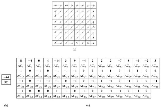
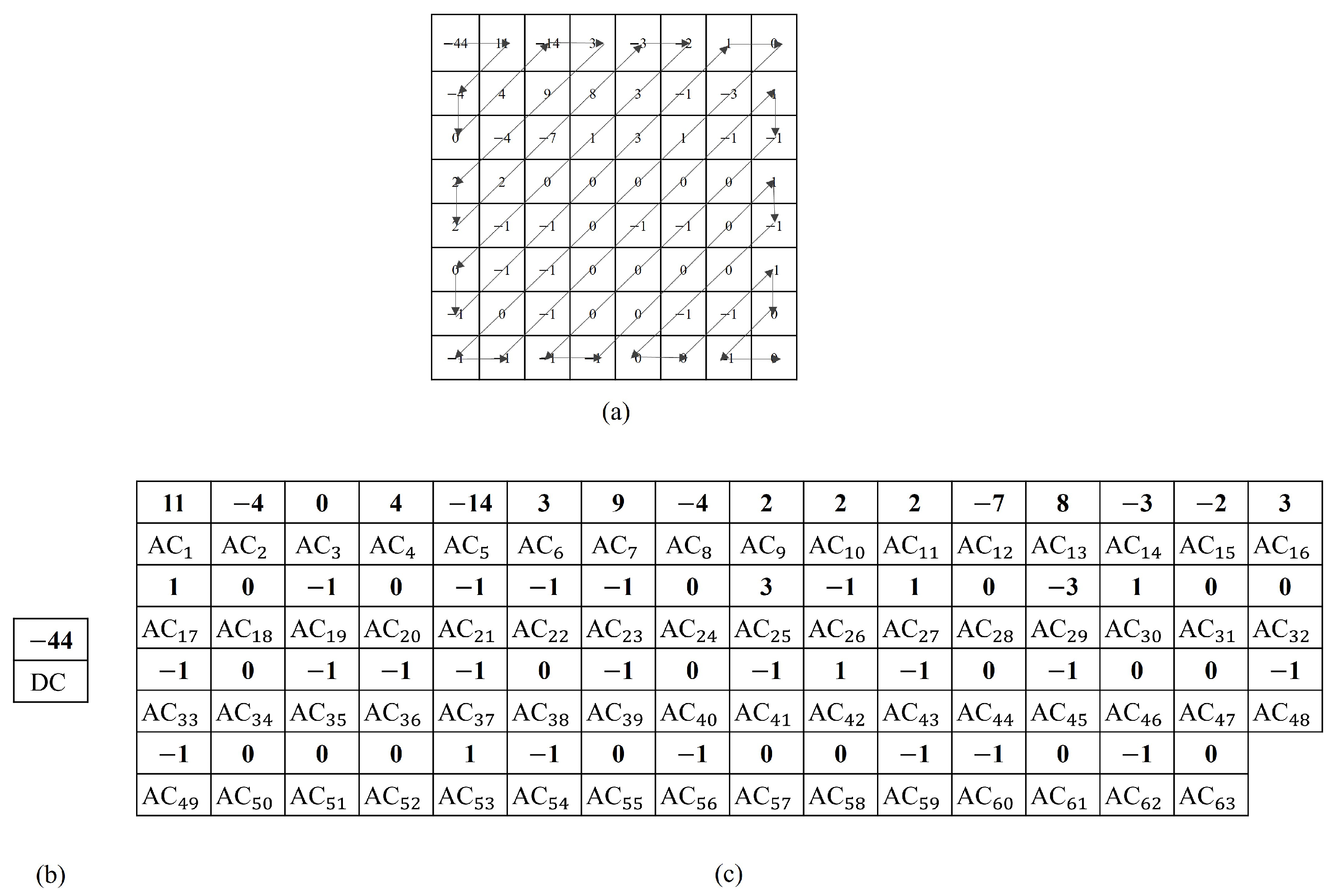


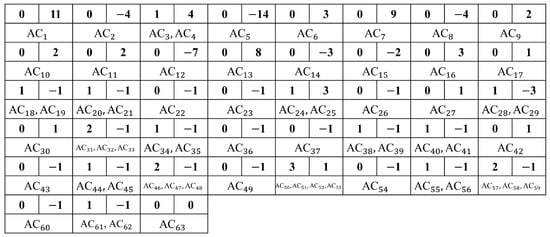
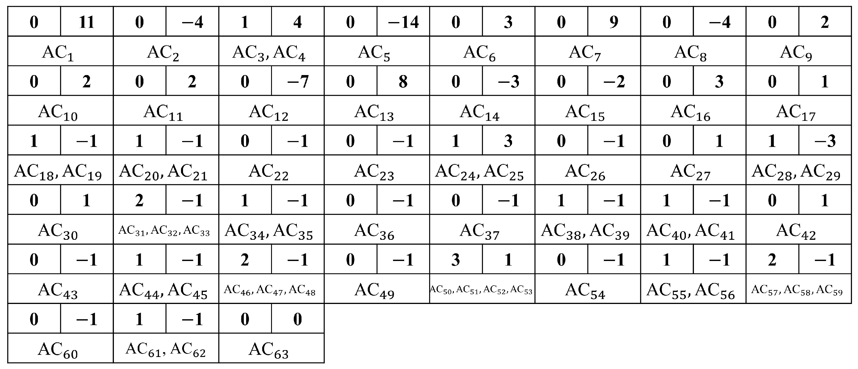
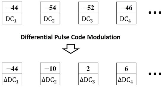
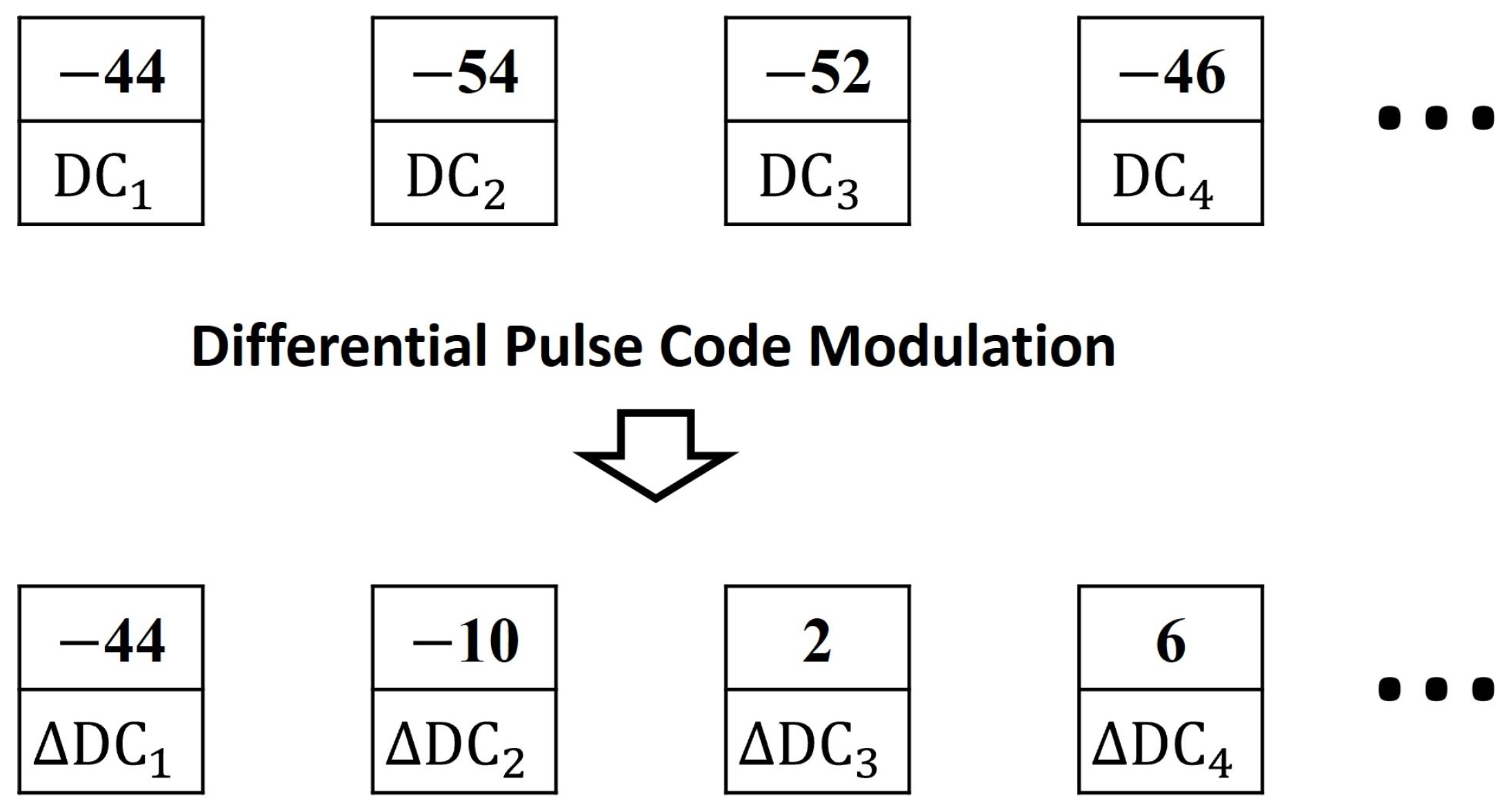
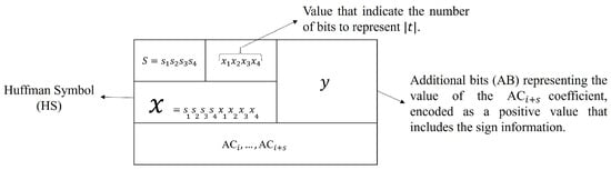
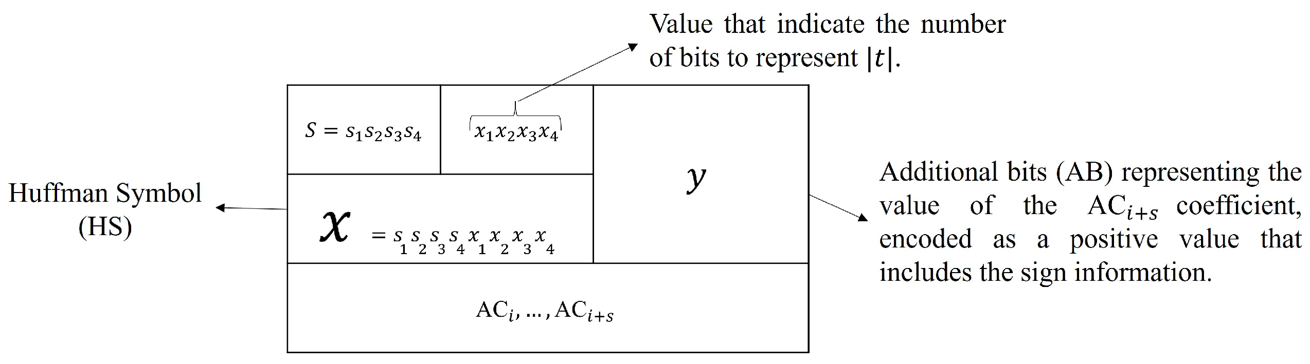
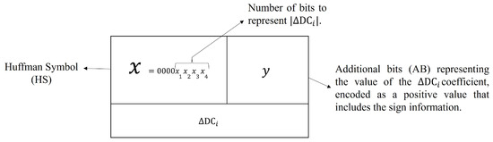
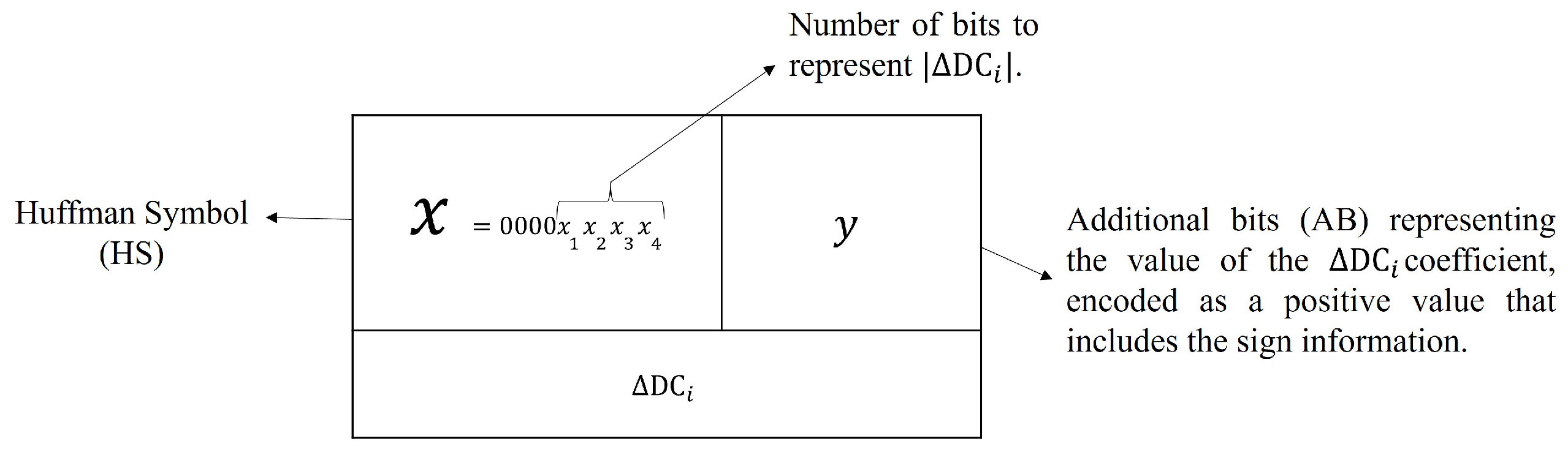
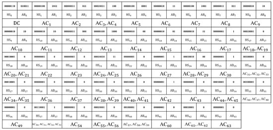
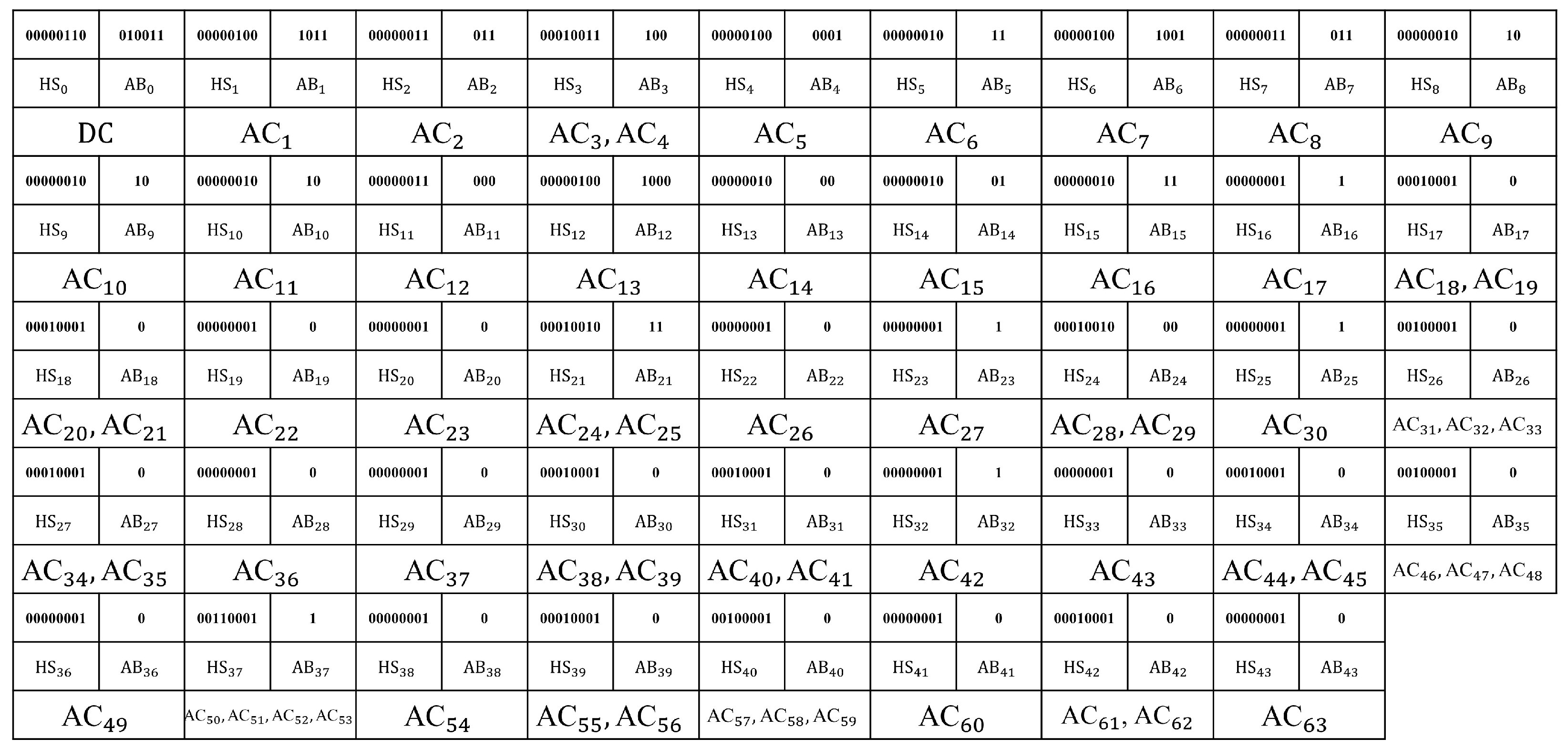
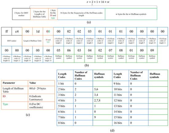
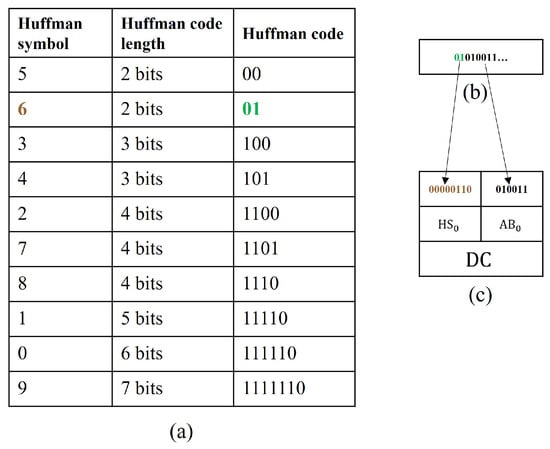
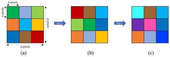
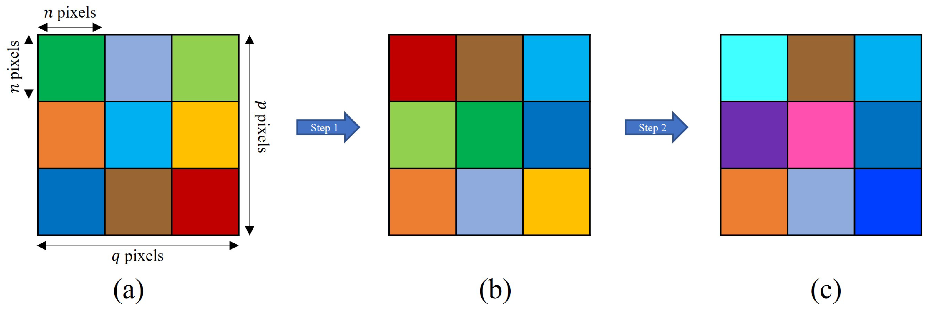
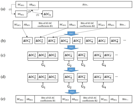
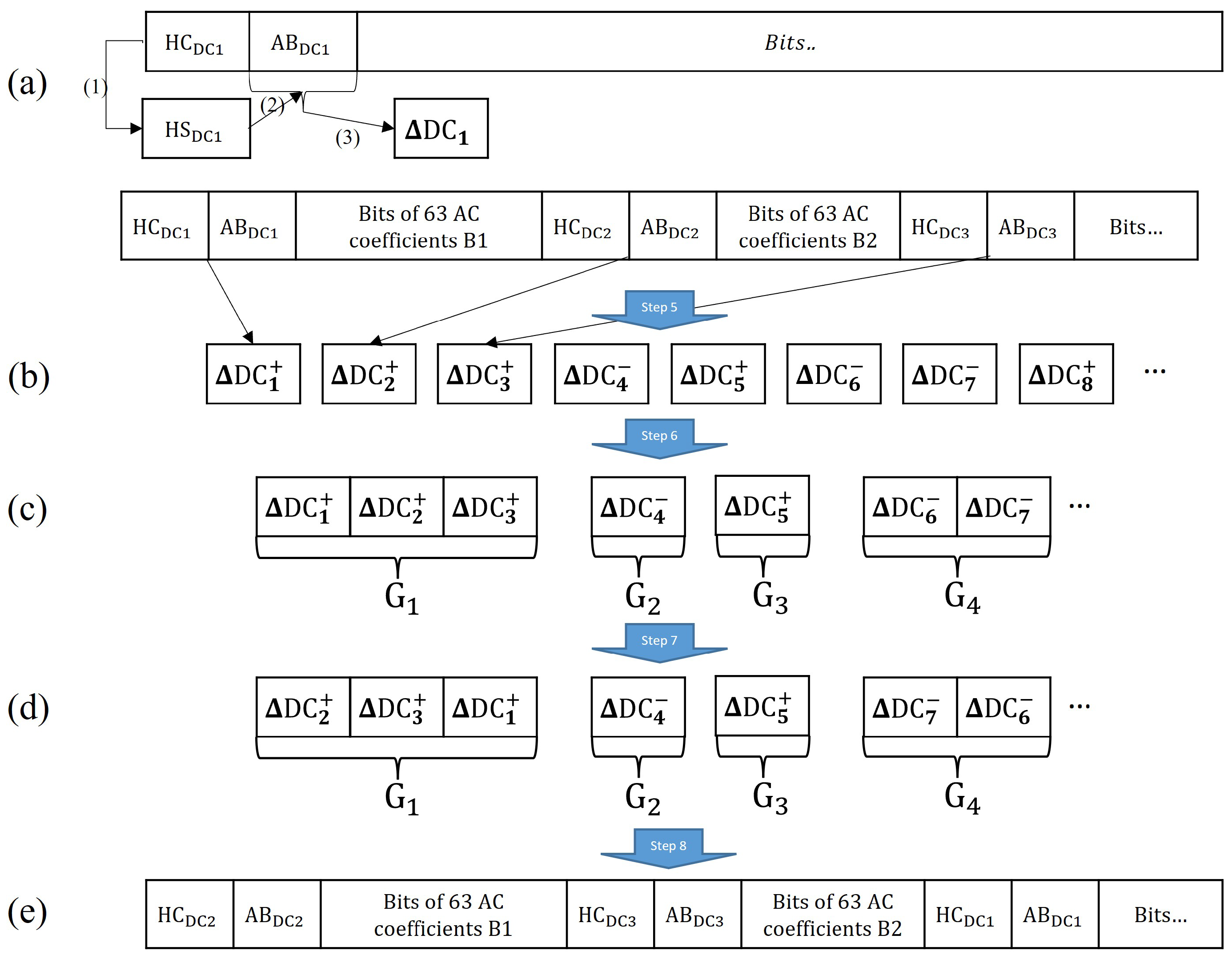
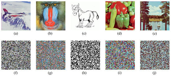
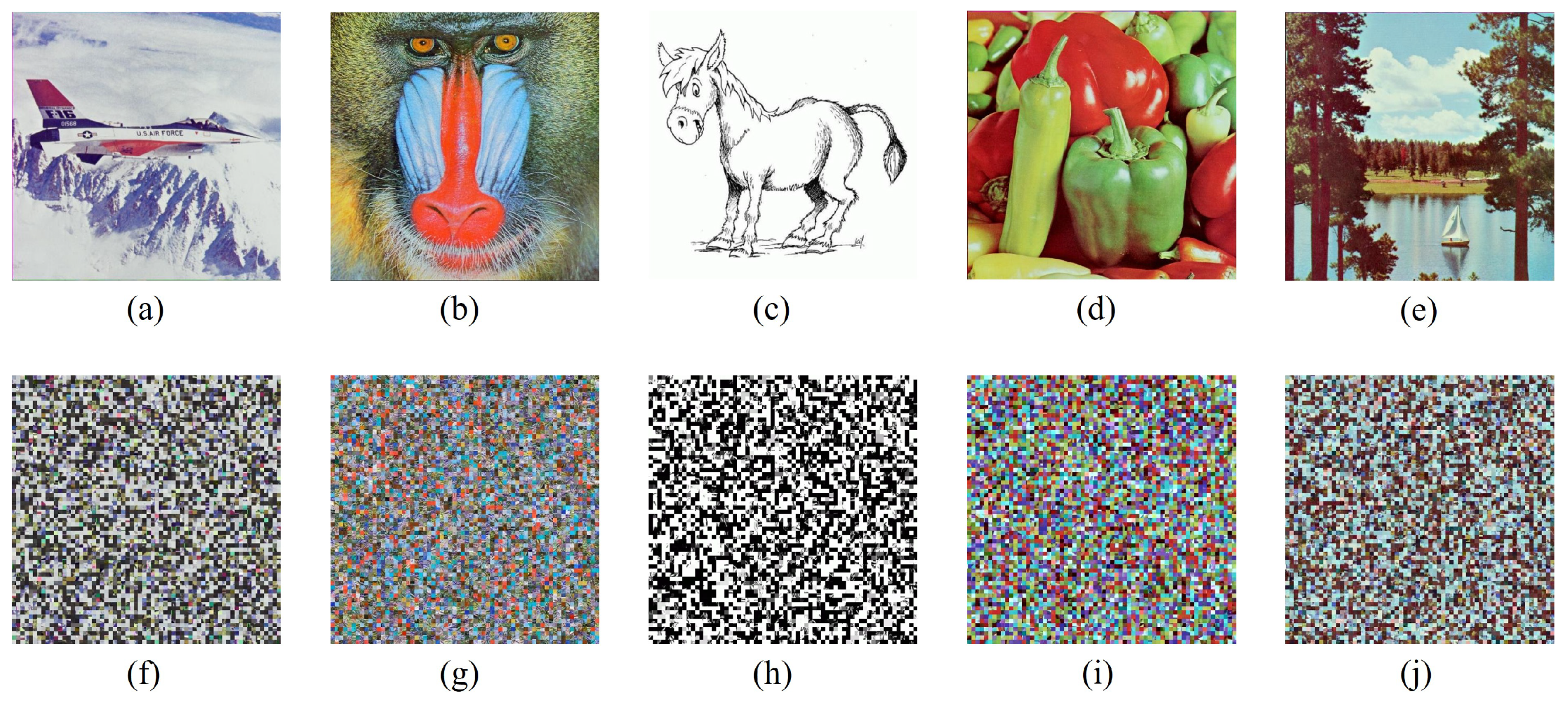
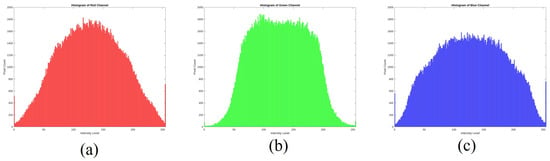
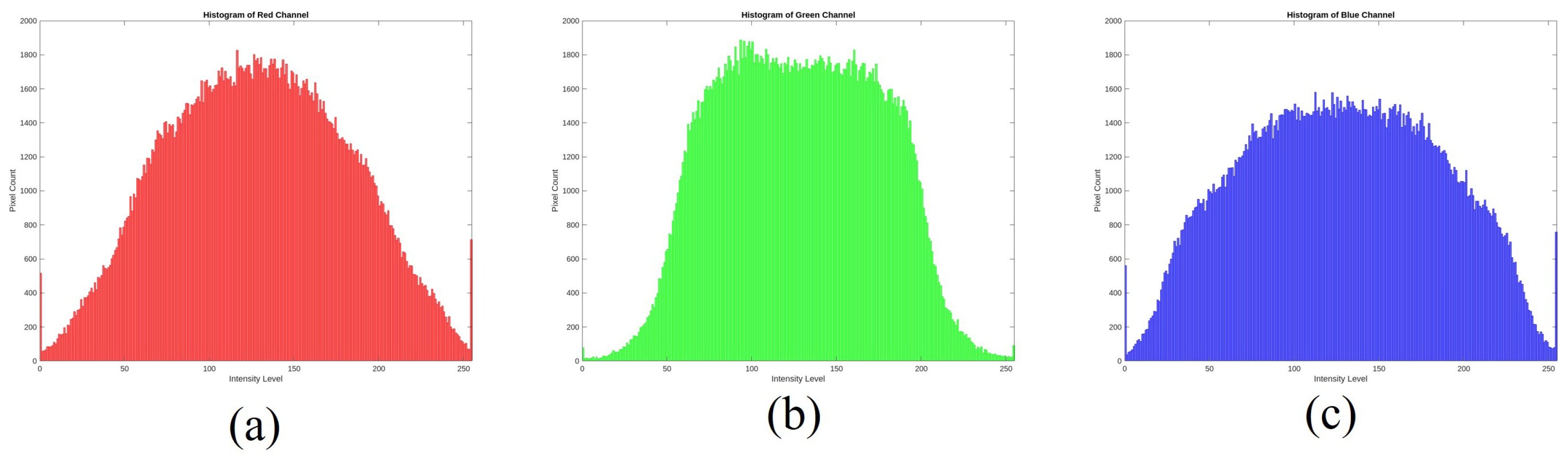

Disclaimer/Publisher’s Note: The statements, opinions and data contained in all publications are solely those of the individual author(s) and contributor(s) and not of MDPI and/or the editor(s). MDPI and/or the editor(s) disclaim responsibility for any injury to people or property resulting from any ideas, methods, instructions or products referred to in the content. |
© 2025 by the authors. Licensee MDPI, Basel, Switzerland. This article is an open access article distributed under the terms and conditions of the Creative Commons Attribution (CC BY) license (https://creativecommons.org/licenses/by/4.0/).