


Abstract
Hydraulic manipulators are vital for heavy-duty applications such as rescue robotics due to their high power density, yet these scenarios increasingly demand safe and compliant physical interaction. Impedance control is a key enabling technology for such capabilities. However, a significant challenge arises when implementing impedance control on Independent Metering Systems (IMS), which are widely adopted for their energy efficiency. The inherent multi-mode operation of IMS relies on discrete switching logic. Crucially, when mode switching occurs during physical interaction with the environment, the unpredictable external forces can trigger frequent and abrupt switching between operating modes (e.g., resistive and overrunning), leading to severe chattering. This phenomenon not only undermines the smooth interaction that impedance control aims to achieve but also jeopardizes overall system stability. To address this critical issue, this paper proposes a seamless control framework based on a Takagi–Sugeno (T-S) fuzzy model. Two premise variables based on the physical characteristics of the system are innovatively designed to make the rule division highly consistent with the dynamic nature of the system. Asymmetric membership functions are introduced to handle direction-dependent switching, with orthogonal functions ensuring logical exclusivity between extension and retraction, and smooth complementary functions enabling seamless transitions between resistance and overrunning modes. Experimental validation on a small hydraulic manipulator validates the effectiveness of the proposed method. The controller eliminates switching-induced instability and smooths velocity transitions, even under dynamic external force disturbances. This work provides a crucial solution for high-performance, stable hydraulic interaction control, paving the way for the application of hydraulic robots in complex and dynamic environments.
1. Introduction
Robots equipped with hydraulic manipulators are increasingly deployed in hazardous and unstructured environments, such as disaster rescue, nuclear decommissioning, and heavy-duty construction [1]. Unlike traditional industrial robots operating in controlled settings, rescue robots must physically interact with unknown environments to perform complex tasks like obstacle clearing and object manipulation. To ensure operational safety and compliant behavior during these interactions, impedance control has become a key enabling technology [2,3]. In addition, these tasks typically require manipulators with high force and payload capabilities. Consequently, hydraulic actuation is commonly adopted in such applications due to its high power density and strong shock resistance. However, the presence of throttling elements in hydraulic systems leads to substantial energy dissipation in the form of heat [4,5]. As a result, the inherently low energy efficiency of hydraulic actuation remains a critical bottleneck, severely limiting the operational duration of mobile rescue platforms.
To address the energy efficiency challenge, the Independent Metering System (IMS), particularly when implemented with digital hydraulic technology, offers a promising solution [6,7]. High-speed on/off valves (HSVs) are one of the core elements of digital hydraulic technology and are typically implemented using poppet- or ball-type structures. Unlike conventional spool valves, HSVs operate in fully open or closed states, thereby significantly reducing throttling losses and improving energy efficiency [8]. By decoupling the meter-in and meter-out flows using multiple valves, IMS enables independent control of actuator motion and chamber pressures [9,10]. This flexibility allows active meter-out back-pressure regulation, reducing pump pressure requirements and overall power consumption [11]. Consequently, IMS achieves higher energy efficiency and improved control performance compared with other energy-saving approaches such as load-sensing systems [12,13]. However, integrating high-performance impedance control with IMS presents a fundamental contradiction. The IMS relies on discrete operating modes to control the cylinder and maximize energy efficiency [14]. During physical interaction, unpredictable external forces often cause the system to oscillate rapidly between these quadrants. For example, shifting between resistive and overrunning modes upon impact.
In conventional IMS control strategies, mode switching is typically triggered by rigid thresholds of pressure and velocity [15,16,17,18]. This “hard-switching” logic introduces abrupt discontinuities in the hydraulic circuit configuration. Specifically, the simultaneous reconfiguration of flow paths and controller gains excites high-frequency dynamics, causing severe pressure spikes and chattering [19]. Moreover, unpredictable external forces from the environment can cause the total load force to frequently and rapidly cross the zero threshold, triggering a cascade of mode switches even when the actuator’s velocity remains constant. Such oscillation not only degrades the tracking performance required for impedance control but can also destabilize the entire robotic system, posing a safety risk in rescue missions.
To address this critical stability issue arising from discrete mode switching, researchers have investigated several approaches to improve system continuity. A continuously variable mode inspired by the gear-shifting mechanism of automotive automatic transmissions was proposed by Shenouda [16], but it requires opening three valves simultaneously during transitions, which complicates control and increases energy loss. Xu [20] proposed a three-level controller to realize pump-valve coordinated control, and a zero-order hold is used to filter the high-frequency mode switch signals. Ding [21] presented a bumpless switching method using dynamic dwell-time theory and a bidirectional potential tracking loop, but the method sacrifices dynamic response speed and reliance on an accurate model. More recently, Lyu [22] used model compensation terms of the desired load force to avoid possible frequent mode switches. Yang [23] proposed a mode switching strategy based on load force direction prediction and chamber pressure switching to avoid frequent switching. However, these methods remain fundamentally discrete approaches, and fail to eliminate signal discontinuities that occur during the switching process. Nguyen [24] proposed a strategy that integrates velocity-load feedforward and position feedback control. Although the transient effects are mitigated by rapid adjustment of control signals, the switching process itself lacks an explicit mechanism to ensure smooth transitions. A variable universe fuzzy controller is designed by Hu [25], which allows for the simultaneous activation of multiple modes. However, this method may also cause multiple valves in the system to open simultaneously, resulting in energy loss. Meng [26] introduced a fixed-valve working mode in which the inlet valve handles pressure control and the outlet valve handles displacement control, eliminating the need for valve function reassignment during load changes. However, when the speed direction changes, the system still adopts a discrete switching method. Zhang [27] employed mathematical smoothing functions to mitigate the pressure shocks and chattering caused by hard switching. Although the methods described above are designed for IMS mode switching, they all lack awareness of IMS’s unique physical characteristics, resulting in a lack of close alignment between the switching logic and the physical state.
On the other hand, the Takagi–Sugeno (T-S) fuzzy model has proven to be a powerful tool for approximating complex nonlinear systems by smoothly blending local linear models [28,29]. However, the application of T-S fuzzy control to IMS presents a unique challenge that remains unaddressed by existing literature. Previous works primarily focus on approximating the continuous nonlinearities of a fixed hydraulic circuit (e.g., a standard servo-valve system) [30,31]. They rarely account for the discrete topological switching inherent to IMS. Consequently, existing fuzzy approaches may achieve parameter smoothing but fail to resolve the chattering caused by the mismatch between the control logic and the distinct physical operating modes.
To bridge this gap, this paper proposes a decoupled hierarchical control architecture. The proposed T-S fuzzy strategy serves as a universal supervisory layer that manages mode transitions based on system physical states, independent of the underlying valve regulation algorithms. The core innovation lies in the introduction of two physical fusion variables: the sliding-type error manifold captures motion intent and the instantaneous load power indicates energy flow. They replace the rigid thresholds of pressure and velocity to proactively identify the system’s dynamic quadrant. Building on a deep analysis of the IMS hardware layout, a hybrid membership function architecture that maps the specific hardware topology of the valve bridge is developed. Orthogonal membership functions are employed for motion direction switching to strictly enforce physical exclusivity between extension and retraction valves. Meanwhile, complementary membership functions are designed for load mode switching (resistive vs. overrunning) to create a soft, overlapping transition zone. This design concludes with a decoupled, universal supervisory framework that manages mode transitions independently of the underlying regulation algorithms, effectively resolving the inherent trade-off between the energy efficiency of IMS and the dynamic stability required for compliant physical interaction.
The structure of this paper is organized as follows. In Section 2, IMS for robot manipulator and its basic principles are introduced. In Section 3, the mathematical model of IMS and impedance control model are established. In Section 4, the T–S Fuzzy control strategy is designed to achieve a stable and smooth switch. In Section 5, the experiments compared to the traditional hard-switch method are conducted to verify the proposed mode switch strategy. The conclusions are presented in the last section.
2. System Principle
2.1. System Structure
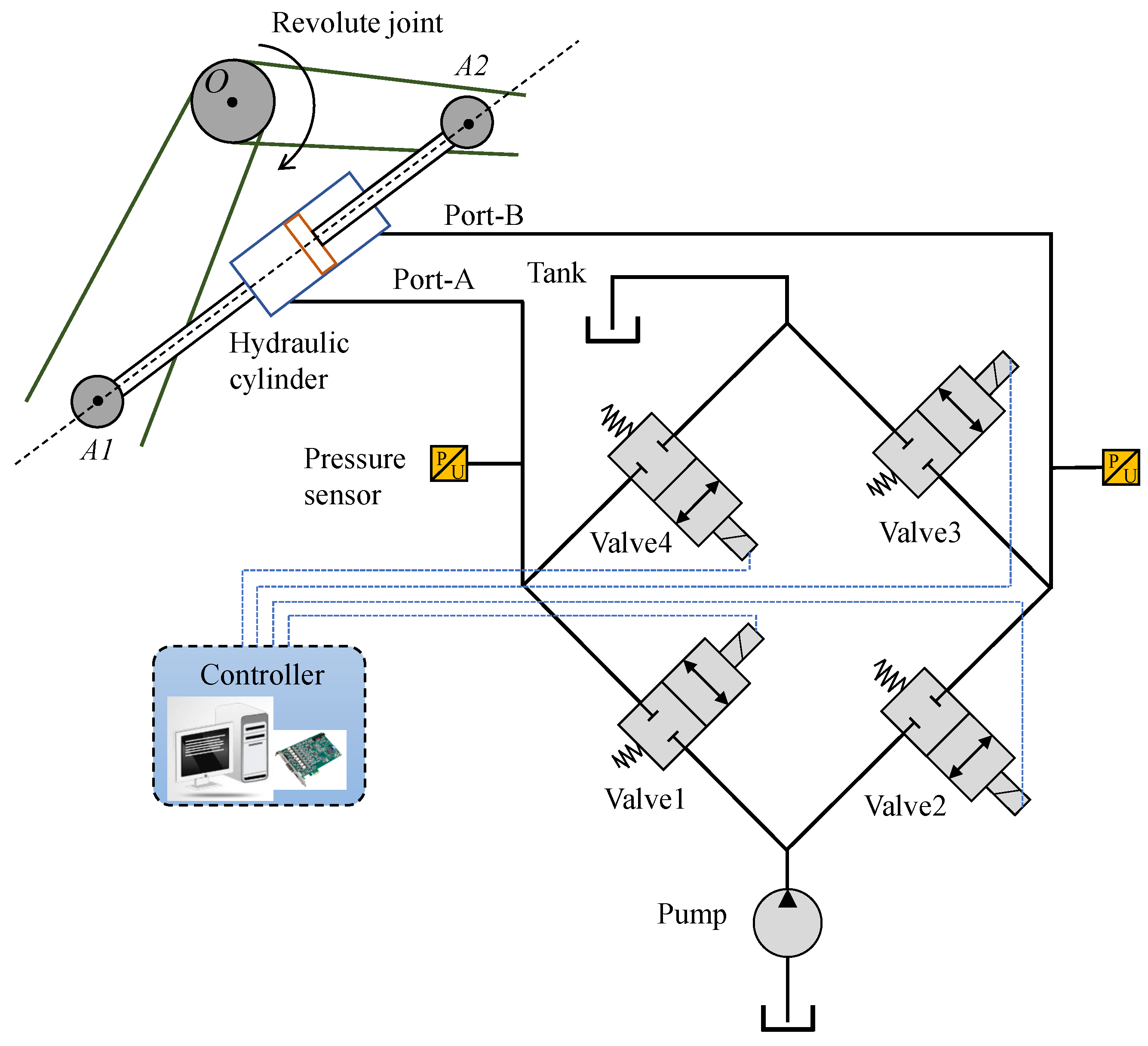
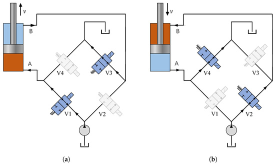
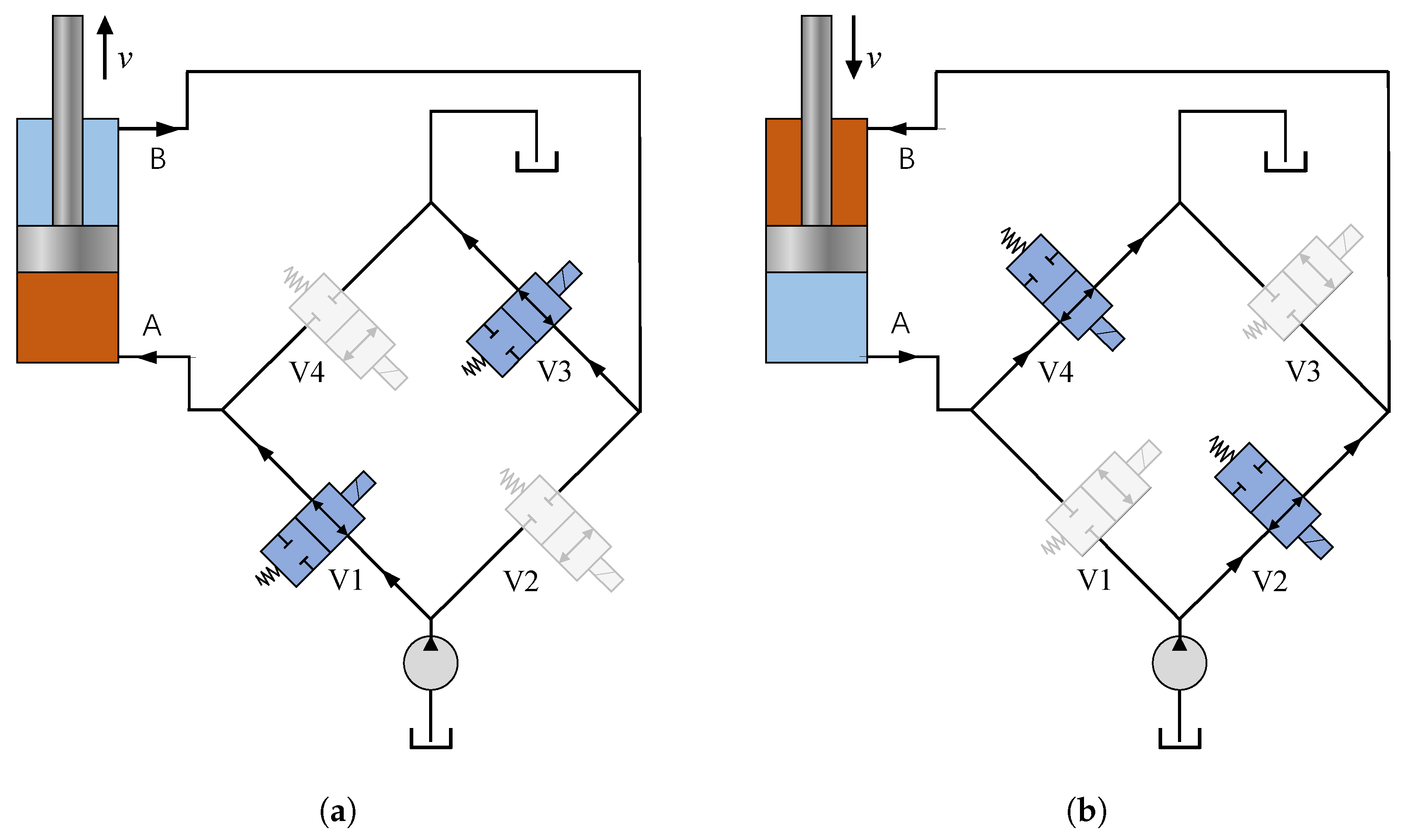
The hydraulic schematic of the system studied in this research with four-valve independent metering is shown in Figure 1. Unlike traditional servo valve-controlled hydraulic cylinder position systems, in which each degree of freedom is managed by a single servo valve, the IMS employs multiple valves per degree of freedom to enable a more flexible control strategy. The IMS employs two separate valves to control the cylinder’s inlet and outlet ports, respectively. As shown in Figure 2a, during extension, Valve1 meters flow from the pump into port A, while Valve3 regulates return flow from port B to the tank. As shown in Figure 2b, during retraction, Valve2 directs pump flow into port B, and Valve4 regulates return flow from port A to the reservoir.
Figure 1.
Schematic diagram of the Independent Metering System (IMS). The system utilizes four independently controlled valves to regulate the meter-in and meter-out flows separately. Black solid lines indicate hydraulic connections; blue dashed lines indicate control signal connections.
Figure 2.
Illustration of the topological switching between extension and retraction modes. The distinct valve configurations required for opposing motion directions demonstrate the inherent physical discreteness of the system, where the active flow paths must be structurally reconfigured. (a) Valve 1 and Valve 3 are actuated when cylinder extends; (b) Valve 2 and Valve 4 are actuated when cylinder retracts.
2.2. Working Principle
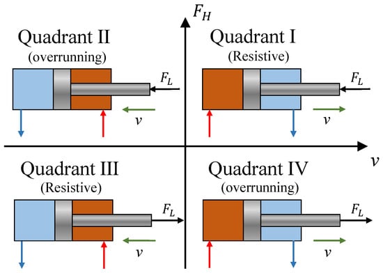
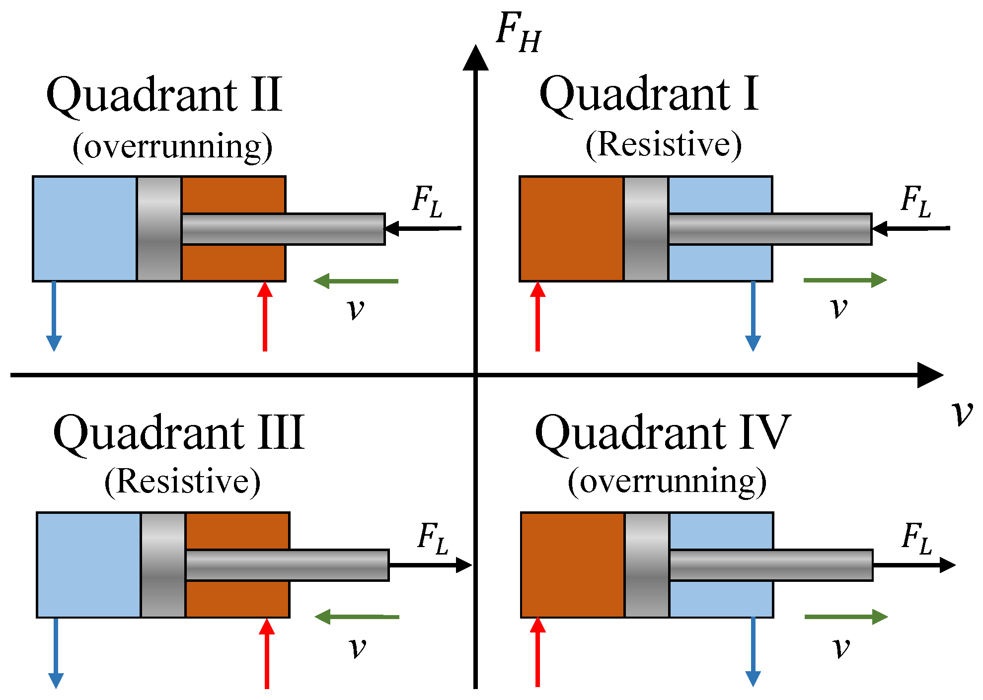
IMS decouples the inlet and outlet ports of a hydraulic cylinder so that flow into and out of the two chambers can be controlled separately. The system’s operation can be categorized into four quadrants, defined by the directions of the actuator’s load force and velocity, as illustrated in Figure 3. Quadrants I and III are defined as resistive when the actuator load force opposes its direction of motion. Conversely, quadrants II and IV are defined as overrunning or load-driven when the load force assists the motion [15].
Figure 3.
The four-quadrant operation map of the hydraulic actuator. The operating modes are categorized by motion direction (Extension/Retraction) and energy flow (Resistive/Overrunning), defined by the relationship between velocity and load force. The hydraulic cylinder operates in resistive mode when velocity v and load force are in opposite directions, and in overrunning mode when they align. Red and blue arrows indicate hydraulic oil inflow and outflow, respectively.
When the cylinder is working in a resistive quadrant, the inlet valve (e.g., valve 1 or 2) is assigned the task of motion control, regulating the flow rate to achieve the desired position of the cylinder. Simultaneously, the corresponding outlet valve (e.g., valve 3 or 4) is managed through pressure control to maintain a specified lower back pressure in the outlet chamber. As a result, the system can operate with a lower supply pressure from the pump compared to conventional systems, leading to significant energy savings.
Once the cylinder enters an overrunning quadrant, the load itself drives the cylinder. The control strategy used for resistive quadrants is no longer suitable. Since the pressure in the outlet chamber is actively controlled at a low level, it becomes impossible to generate sufficient back pressure to decelerate the piston. To regain control over piston motion, the outlet valve (e.g., valve 3 or 4) must switch from pressure control to position control, thereby generating sufficient back pressure to regulate the piston’s position. Meanwhile, the corresponding inlet valve (e.g., valve 1 or 2) is typically commanded to control the inlet chamber pressure or is set to full open to prevent potential cavitation. This approach also allows for a reduction in the pump supply pressure, as only a lower pressure is needed to replenish the inlet chamber, further enhancing the system’s energy efficiency. In some advanced implementations, a flow-regeneration mode is employed.
2.3. Operating Modes Classification
To enable impedance control in IMS, the hydraulic circuit must operate in a mode that allows the system to actively control the dynamic relationship between force and motion. Under overrunning load conditions, some studies have adopted a flow-regeneration strategy, in which fluid discharged from the hydraulic actuator is rerouted through a valve back into its inlet chamber [24,32]. This strategy is energy-efficient and particularly well suited for constant-load scenarios, such as the lowering phase of a loaded excavator arm or crane boom. However, when external forces are variable and unpredictable in a rescue mission, the actuator cannot generate sufficient and controllable output force to perform an accurate and robust impedance control. Therefore, the flow-regeneration mode is not suitable for conventional impedance control.
In robot–environment interaction tasks, control stability and operational safety are of primary importance. For these reasons, the working mode of the IMS in this study is specially designed to achieve high-performance impedance control. According to the load quadrant of the hydraulic cylinder, the working modes are divided into four types:
- (1)
- Powered Extension Mode (PE)
In PE mode, the hydraulic cylinder operates in the first quadrant. The meter-in valve 1 signal directs high-pressure oil into the rodless chamber to extend the cylinder and regulate its motion, while the meter-out valve 3 signal vents the rod chamber to the low-pressure tank to maintain a low backpressure. This configuration is standard in impedance-modulated control (IMC) systems.
- (2)
- Powered Retraction Mode (PR)
In PR mode, the hydraulic cylinder operates in the third quadrant. The meter-in valve 2 signal supplies high-pressure oil to the rod chamber to retract the cylinder and regulate the motion, while the meter-out valve 4 signal vents the rodless chamber to the low-pressure tank to maintain a low backpressure.
- (3)
- Controlled Overrunning Extension Mode (COE)
In COE mode, the hydraulic cylinder operates in the fourth quadrant and is driven by the external load. Under this mode, valve 3, controlled by , vents the rod chamber and regulates the piston motion, whereas valve 1, actuated by the signal , maintains a steady pressure in the rodless chamber to prevent cavitation.
- (4)
- Controlled Overrunning Retraction Mode (COR)
In COR mode, the hydraulic cylinder operates in the second quadrant and retracts under the external load. The meter-out valve 4, controlled by the signal , routes the outflow to the tank and regulates the piston motion, while valve 2, actuated by , regulates the inlet pressure to prevent cavitation.
2.4. Mode Switching Challenge
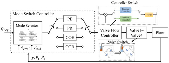
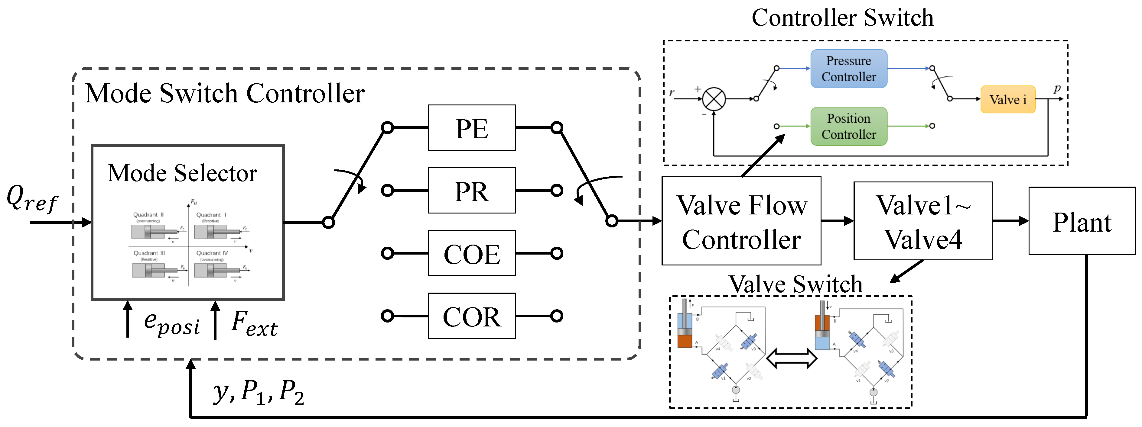
As mentioned above, because of the existence of these distinct operating modes, a switching control mechanism is needed so that the controller can transition between them as conditions change. In practical applications, variations in control inputs or external load forces frequently lead to changes in the load quadrant of the hydraulic cylinder. Under such circumstances, the IMS controller must either switch the operating valve or reconfigure the valve controller. This process is referred to as mode switching, as shown in Figure 4. When the switching criterion is formulated on the basis of a sign function, its inherent non-smoothness forces the control command to jump instantaneously between modes once the switching threshold is crossed. In a hydraulic system with low compliance and high dynamic bandwidth, such abrupt changes in valve states cause sudden reconfiguration of flow paths and rapid chamber pressure variations. These discontinuities excite high-frequency dynamics in the mechanical system, leading to sudden parameter shifts and, in turn, triggering mode-switching oscillations.
Figure 4.
Architecture of the conventional hard-switching controller. The discrete mode selector triggers abrupt transitions based on fixed velocity and pressure thresholds. This rigid logic leads to controller discontinuity and valve chattering when the system state fluctuates near the switching boundaries.
3. Model Establishment
3.1. System Mathematical Model
In this work, a double-acting hydraulic cylinder controlled by an IMS is considered. The system is modeled in the linear cylinder coordinate, where the piston displacement y is defined as positive when the piston moves outward, resulting in an increase in the rodless chamber volume. The hydraulic force acting on the piston is generated by the pressure difference between the two chambers and is given by:
where and denote the pressures in the rodless and rod chambers, respectively, and and the corresponding effective piston areas. The linear dynamics of the piston–load system are described by:
where m represents the equivalent moving mass, is the external load force acting on the piston, and denotes the friction force.
To account for the nonlinear friction characteristics inherent in hydraulic actuators, the friction force is modeled using a simplified friction model without Stribeck effect:
where and denote the Coulomb and viscous friction coefficients, respectively.
Assuming no internal or external leakage, the pressure dynamics of the two chambers are governed by the continuity equations:
where and are defined as the flow rates into the rodless and rod chambers, respectively, is the effective bulk modulus of the hydraulic fluid, and denote the total control volumes of the rodless and rod chambers, respectively, and are the initial chamber volumes corresponding to the position .
The flow rates through the independent metering valves are modeled using the standard orifice equation
where denotes the valve index, is the discharge coefficient, w is the area gradient, is the spool displacement, is the oil density, and is the pressure difference across the i-th valve.
Define the state variables of a single degree-of-freedom joint as:
Then, the state space representation of a robot joint controlled by IMS can be described by employing (1)–(6)
where is the external force acting on the cylinder, and is the friction.
3.2. Contact Force Estimation
The manipulator joints are actuated by hydraulic cylinders, and the hydraulic force generated by cylinder is transmitted to the corresponding joint as an equivalent driving torque through the mechanism geometry. Specifically, the joint driving torque produced by the hydraulic actuator can be expressed as:
where denotes the geometry-dependent force–torque mapping between the hydraulic actuator and the joint. The relationship between the joint torque and the Cartesian contact force is given by , is the standard robot Jacobian. The dynamics of the manipulator in the joint space are expressed as follows:
where denote the joint position, velocity and acceleration, respectively. is the inertia matrix, is the vector of Coriolis/centrifugal torques, is the vector of gravitational torques, is the friction torque result from the cylinder friction force modeled in Equation (3). Consequently, the external force is estimated by projecting the joint torque residual onto the task space using the pseudo-inverse of the Jacobian transpose:
3.3. Impedance Model
The objective of impedance control is to endow the robot with a desired impedance behavior, which is essential for modulating and controlling the dynamic interaction between the manipulator and the environment. The impedance control scheme is established in the joint space to regulate the dynamic relationship between joint torque and angular motion. The model is described as follows:
where denotes the angular deviation from the nominal (desired) joint trajectory; denotes the desired external force; and are the desired inertia, damping, and stiffness matrices, which are diagonal and positive definite. When no contact force is specified, is set to zero.
The final joint position command is obtained by superposing the impedance output onto the desired trajectory:
Since the hydraulic cylinders are controlled in the actuator space, the commanded joint position is transformed into the equivalent cylinder displacement via the mechanism’s inverse kinematics. This value then serves as the reference for the inner position control loop to drive the hydraulic cylinder based on the dynamics defined in Equation (8).
4. Mode Switch Controller Design
4.1. Takagi–Sugeno (T-S) Fuzzy Controller Design
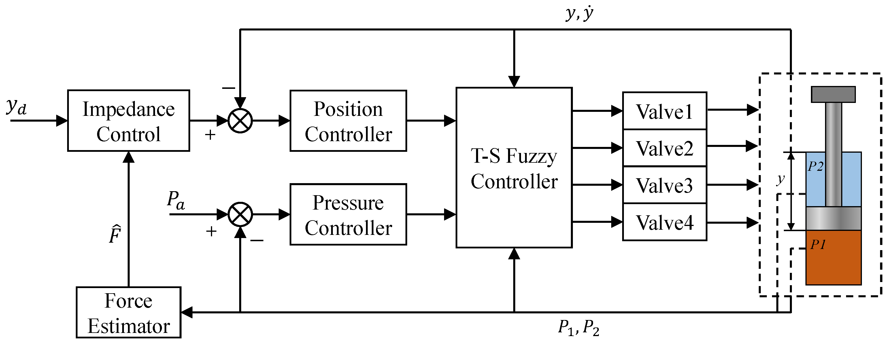
The T-S fuzzy controller is responsible for mode switching, the purpose of which is to make the switching process smooth. As shown in Figure 5, the fuzzy controller is used to intelligently fuse and distribute the signals from the previous controllers. To effectively navigate the four operating quadrants (see Figure 3), the controller must continuously assess the system’s state along two fundamental and independent axes: the direction of motion and the energy exchange direction with the load. Therefore, two physically meaningful premise variables are designed to accurately distinguish the four operating modes. Based on the mathematical model established in Section 3, the position tracking error is defined as , where is the desired trajectory. In order to distinguish the motion direction of the cylinder, a sliding-type error manifold is introduced as a premise variable:
where is a positive constant that adjusts the weight of the position error in the manifold. Based on the definition of position error, a negative implies the system is lagging or needs to accelerate in the positive direction (extension), while a positive indicates the system is overshooting or needs to move in the negative direction (retraction). To distinguish whether the hydraulic cylinder is working in resistance mode or overrunning mode, the instantaneous load power is chosen as the second premise variable. It can reflect the energy flow between the actuator and the external load:
A positive indicates an overrunning condition (the load delivers energy to the actuator), while a negative indicates a resistive condition (the actuator supplies energy to the load).
Figure 5.
The proposed decoupled hierarchical control architecture. The T-S fuzzy supervisor functions as a universal “fusion unit,” smoothly blending control signals from local executives. Note that the local “Position Controller” and “Pressure Controller” can employ any advanced control algorithm, as the fuzzy fusion logic acts independently to manage the smooth transition of control authority.
Based on the premise variable , two fuzzy sets that represent the motion direction of the cylinder, Extension (E) and Retraction (R), are defined. To obtain soft transitions between modes, smooth membership functions are employed. A hyperbolic tangent (tanh) kernel is used as a smooth mapping, so their respective membership functions, and , are defined as:
where is a smoothness factor, which is a small positive constant that regulates the smoothness of the switching band. The above two membership functions are designed to be mutually exclusive, ensuring that extension and retraction commands are mutually exclusive. Note that .
For the premise variables , two fuzzy sets are defined: Resistive (RES) and Overrunning (OVR). Their membership functions, and , are defined as follows:
where is also a smoothness factor for regulating the power-based switching band. This pair of functions ensures that the sum of the control weights for both conditions is always unity, realizing a smooth “fade-in/fade-out” of two control strategies.
The overall control logic is encapsulated in a T-S fuzzy rule base consisting of four rules, corresponding to all possible combinations of the defined fuzzy sets and operating modes. The consequent part of each rule specifies a local control law vector , which represents the output rule of the corresponding subsystem under each rule.
Rule 1: Extension-Resistive
IF is E AND is RES
THEN
Rule 2: Retraction-Overrunning
IF is R AND is OVR
THEN
Rule 3: Retraction-Resistive
IF is R AND is RES
THEN
Rule 4: Extension-Overrunning
IF is E AND is OVR
THEN
The firing strength of each rule is calculated as follows:
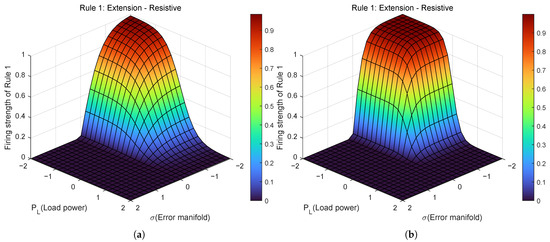
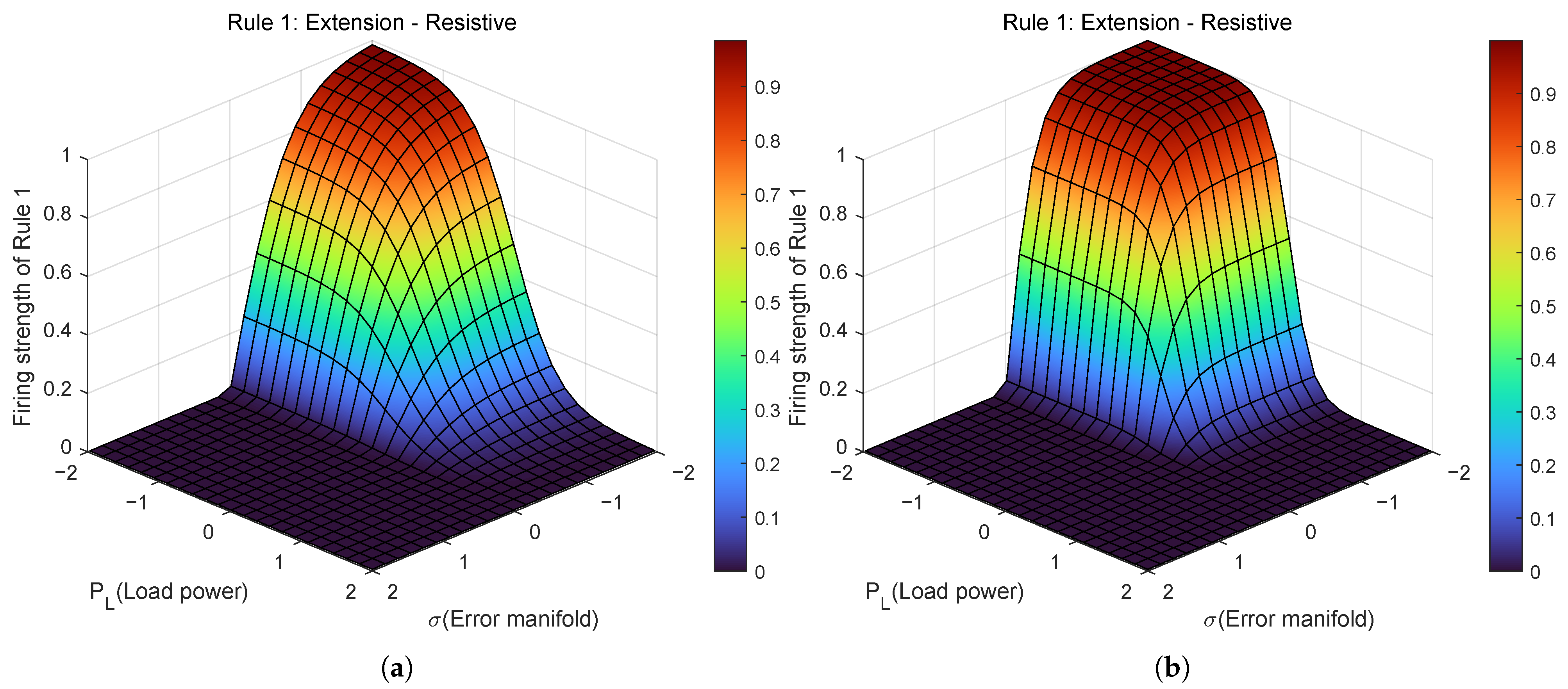
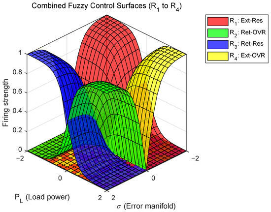
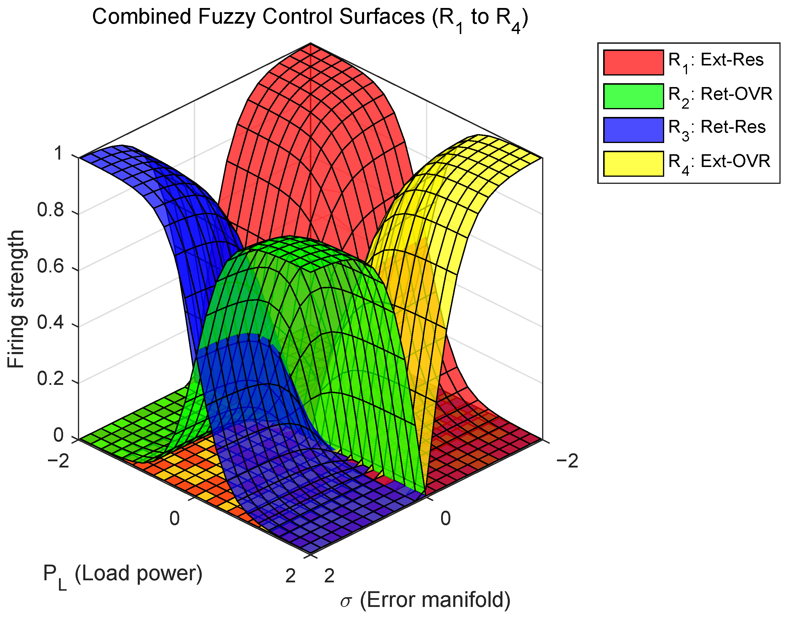
To provide a deeper insight into the controller’s behavior, Figure 6 illustrates the control surface for Rule 1 (Extension-Resistive), and its sensitivity to the tuning parameters. Here, the z-axis (firing strength) represents the activation weight of the rule, serving as a direct indicator of its control authority. When the firing strength equals 1, Rule 1 is fully activated, implying the hydraulic system is strictly operating within quadrant 1. Comparing Figure 6a,b reveals the impact of the smoothness factors and . As shown in Figure 6b, smaller parameters result in steeper gradients at the boundaries compared to Figure 6a, corresponding to a fast transition between rules. The final control output is synthesized by blending the local control laws according to their corresponding firing strengths. Figure 7 provides a clear visualization of how the controller’s fuzzy rules in different load quadrants are fused together. At any given moment, the system state is represented by a point on the plane, and the height of the surface (firing strength) determines which local controller (or combination thereof) dominates the output. Crucially, the surface topology visualizes the proposed hybrid switching logic. The separation along the -axis and between the positive and negative regions reflects the logical orthogonality, ensuring that extension and retraction valves are never fully active simultaneously to prevent hydraulic short-circuits. The continuous, overlapping gradients along the -axis reflect the soft complementarity, facilitating a seamless hand-off between resistive and overrunning controls without discontinuities.
Figure 6.
Visualization of the control surface for Rule 1 (Extension-Resistive) with different smoothness factors. (a) Surface with larger factors (), resulting in a slower transition. (b) Surface with smaller factors, showing steeper firing strength gradients and faster switching behavior. The Z-axis represents the firing strength (weight), indicating the rule’s control authority. (a) Control surfaces of Rule1 with larger smoothness factors; (b) Control surfaces of Rule1 with smaller smoothness factors.
Figure 7.
The total synthesized control surface fusing all four rules. The geometric topology reflects the hybrid physical constraints: the distinct separation along the -axis reflects the logical orthogonality between extension and retraction, while the continuous gradients along the -axis reflect the smooth complementary transition for reversing loads.
The total control output vector is then computed as the weighted average of the consequent control vectors.
4.2. Stability Analysis
The error dynamics expressed under the T-S fuzzy control framework can be expressed as:
where is the error state, and are the state and input matrices of the local subsystem, is the controller gain matrix for the rule, are the normalized firing strengths.
To analyze the stability, we consider a common quadratic Lyapunov function candidate:
The time derivative of is given by:
where . For to be negative definite, it is sufficient that the matrix term within the brackets is negative definite. The term introduces a polytopic uncertainty within the interval . Stability across this entire range can be guaranteed if the conditions hold at the vertices of this uncertainty polytope, i.e., for and . This leads to the following stability theorem.
Theorem 1.
The inner-loop system’s origin is globally asymptotically stable if a symmetric matrix exists that satisfies the following Linear Matrix Inequalities (LMIs) for all :
(1) For the vertex :
(2) For the vertex :
To verify the proposed stability conditions, the local subsystem matrices and () were derived by linearizing the nonlinear hydraulic dynamics (Equation (8)) at the equilibrium points of each quadrant. The LMI conditions in Theorem 1 were solved using the YALMIP toolbox (see Appendix A for the detailed matrix structures and stability result). The existence of such a positive definite P mathematically guarantees the global asymptotic stability of the closed-loop system under the proposed switching laws.
5. Experiment
5.1. Experimental Setup
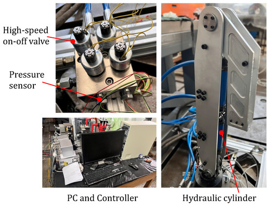
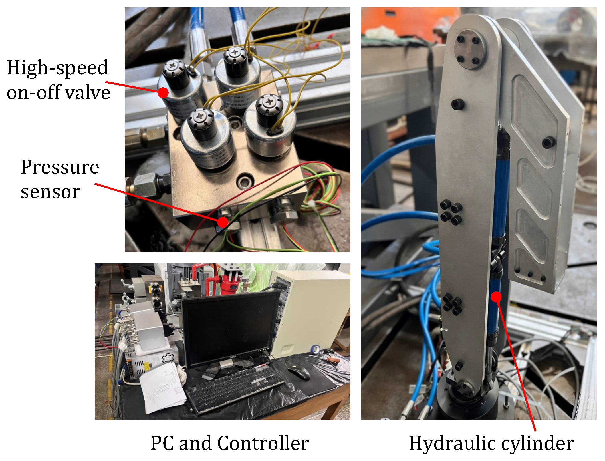
Experiments were carried out to verify the effectiveness of the proposed T-S fuzzy controller. The test rig is a self-developed hydraulic manipulator, as shown in Figure 8. The cylinder diameter was 20 mm, and the piston rod diameter was 12 mm. Four high-speed on-off valves (Model MGHSV3201s4; Guizhou Mangwei Technology Co., Ltd., Guiyang, China) were employed to control one cylinder, which were driven by a PWM signal at 100 Hz. The position and velocity of the joint were measured by angle encoders (Shenzhen Briter Encoder Co., Ltd., Shenzhen, China). Two pressure sensors (Model PPM-T320A; Baoji Taihe Electronics Co., Ltd., Baoji, China) were mounted on the valve block to measure the cylinder chamber pressure. Two PCI boards (Advantech Co., Ltd., Taipei, China) were utilized for real-time control and data processing. The working pressure of the hydraulic system is set at 8 MPa. For the T-S fuzzy switching controller proposed in this paper, the gain for the sliding-mode error manifold used to define the motion direction is 2, and the smoothness adjustment factors for the membership functions are set to and .
Figure 8.
Equipment used in experiments.
In the following experiments, to focus on the performance of the mode-switching mechanism, standard Proportional-Integral (PI) controllers are employed for the local subsystems. Specifically, for a resistive mode, the meter-in valve control signals and are designed to track the cylinder position, while the meter-out valve signals and regulate the back pressure. In the overrunning mode, the meter-in valve signals and are designed to regulate the inlet pressure, whereas the meter-out valve signals and are responsible for controlling the cylinder motion.
The control signal for the valve assigned to motion tracking () and the valve assigned to pressure regulation () are computed as:
where is the measured pressure of the pressure control chamber, and is the desired pressure. and are the control gains. The control gains were determined through simulation and experimental tuning, and these parameters were kept unchanged in the comparative experiments. In the impedance control, the desired inertia is not considered, the desired joint stiffness is 80 Nm/rad, and the desired joint damping is 3 Nms/rad.
To mitigate the measurement noise inherent in hydraulic pressure sensors and the amplification of noise due to numerical differentiation of angle encoder, a second-order Butterworth low-pass filter and a Kalman filter are applied to the pressure sensor and the angle encoder.
Two baseline methods are employed for comparison:
Hard-Switching Control: The traditional logic that switches based on velocity and pressure thresholds.
Sigmoid-based Soft-Switching Control: A smooth switching strategy [27] that utilizes a Sigmoid function to continuously blend control modes based on position error thresholds.
5.2. Test 1: Quasi-Static Physical Interaction
In this experiment, an external force was manually applied to and subsequently removed from the end-effector of the stationary manipulator to evaluate the mode-switching performance during quasi-static human–robot interaction. When the external force is applied, as highlighted by the blue shaded region in Figure 9, the operating mode transitions from the static state to the overrunning mode. Upon removal of the external force (corresponding to the gray shaded region in Figure 9), the system shifts to the resistive mode and eventually reverts to the static state as the piston returns to its initial position.
Figure 9.
Comparative experimental results under quasi-static physical interaction. The blue shaded region indicates the phase where an external force is manually applied (transition from static to overrunning), while the gray shaded region represents the unloading and recovery phase (transition from resistive to static). The proposed T-S fuzzy method demonstrates the fastest recovery with minimal overshoot compared to the Hard-Switching and Sigmoid Soft-Switching. (a) Position tracking trajectories of the hydraulic cylinder; (b) Estimated external contact forces.
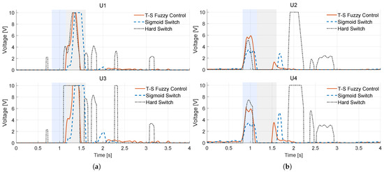
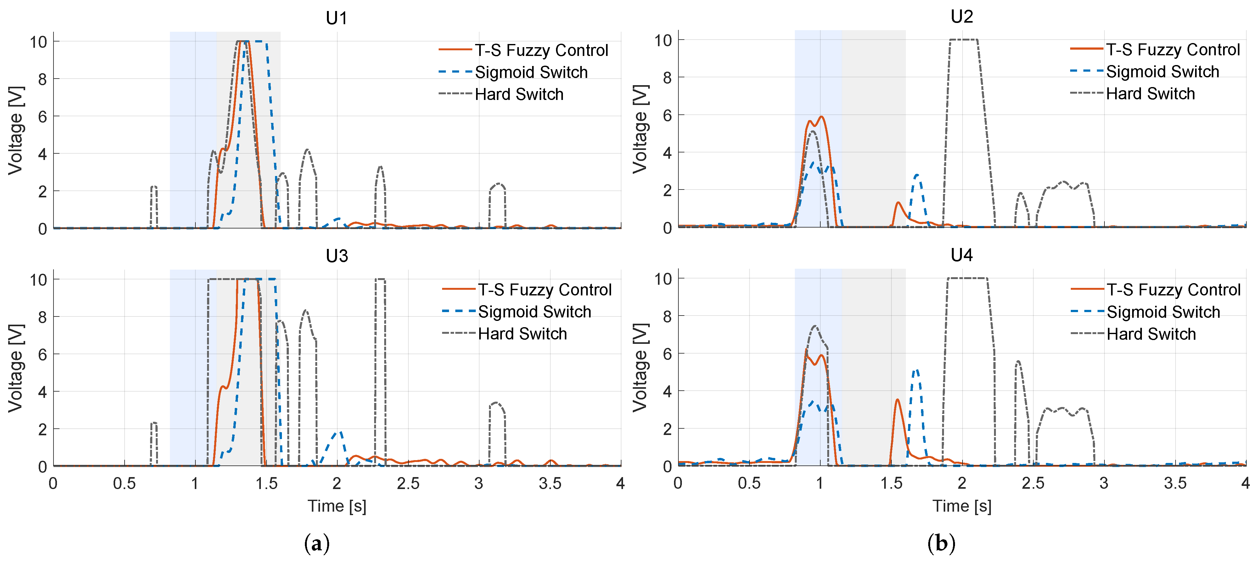
Comparative analysis reveals the superiority of the proposed method. The T-S fuzzy strategy achieves the best trade-off between stability and responsiveness, exhibiting minimal overshoot and the fastest settling time. In contrast, the hard-switching method causes severe chattering during the recovery phase due to discontinuous control logic. Although the sigmoid soft-switching baseline successfully suppresses these oscillations, it introduces a noticeable phase lag, resulting in a slower recovery. Further insight is provided by the estimated contact force (Figure 9b) and valve control signals Figure 10. Despite utilizing identical local PI control laws, the valve signals modulated by the T-S fuzzy supervisor are significantly smoother compared to the abrupt steps in hard-switching. This validates that the proposed fuzzy blending effectively filters high-frequency chattering without sacrificing bandwidth. Table 1 summarizes the quantitative performance metrics averaged over multiple experimental trials.
Figure 10.
Control voltage signals of the four independent metering valves during the quasi-static interaction experiment. The blue shaded region indicates the phase where an external force is manually applied, while the gray shaded region represents the unloading and recovery phase. (a) Valve control voltage of Valve 1 and Valve 3; (b) Valve control voltage of Valve 2 and Valve 4.
Table 1.
Performance Comparison.
5.3. Test 2: Dynamic Impact Interaction
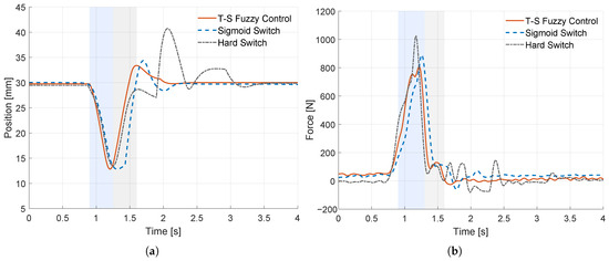
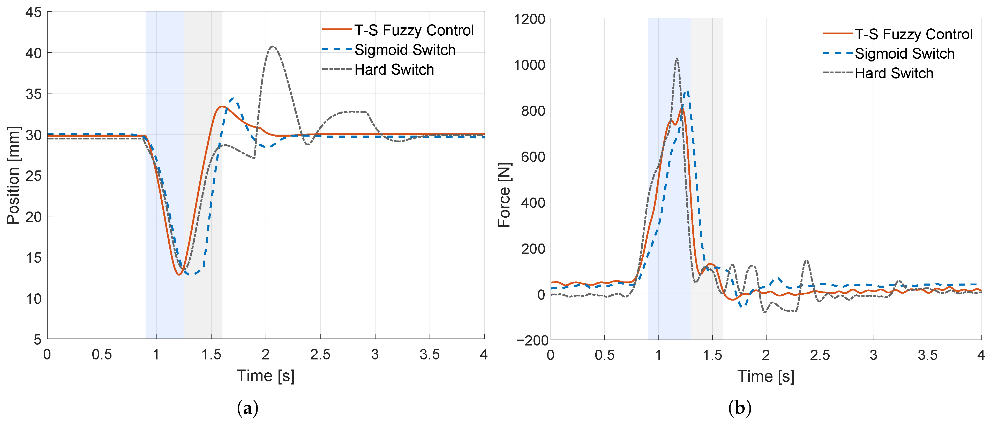
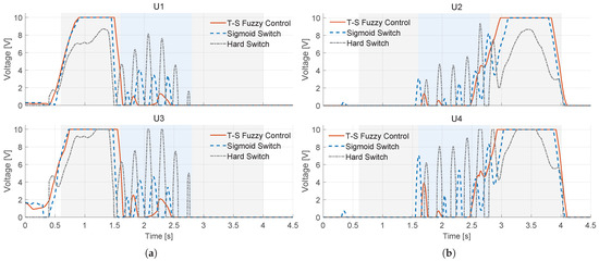
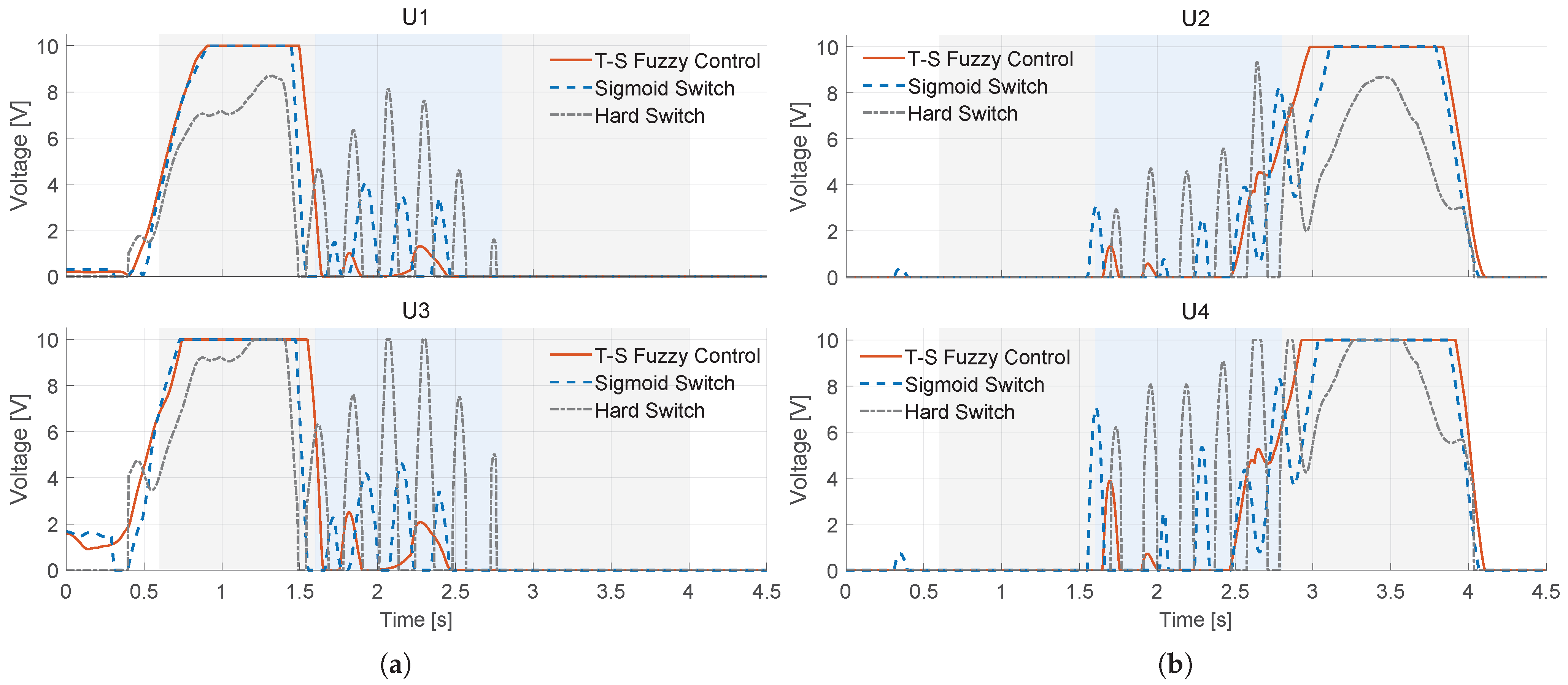
To further investigate the robustness of the controller under sudden, high-intensity physical impacts, a dynamic impact experiment was conducted. In this scenario, the manipulator tracked a velocity trapezoidal trajectory with a maximum velocity of 15 mm/s until its end-effector collided with a fixed, rigid obstacle. Theoretically, upon impact, the hydraulic cylinder is required to transition instantaneously from the resistive extension mode to a static state, and subsequently resume motion once the trajectory command clears the obstacle.
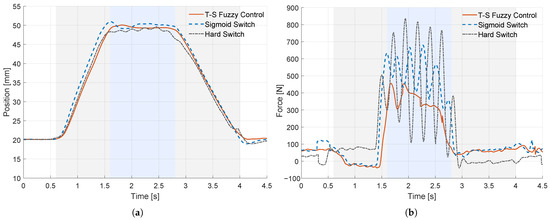
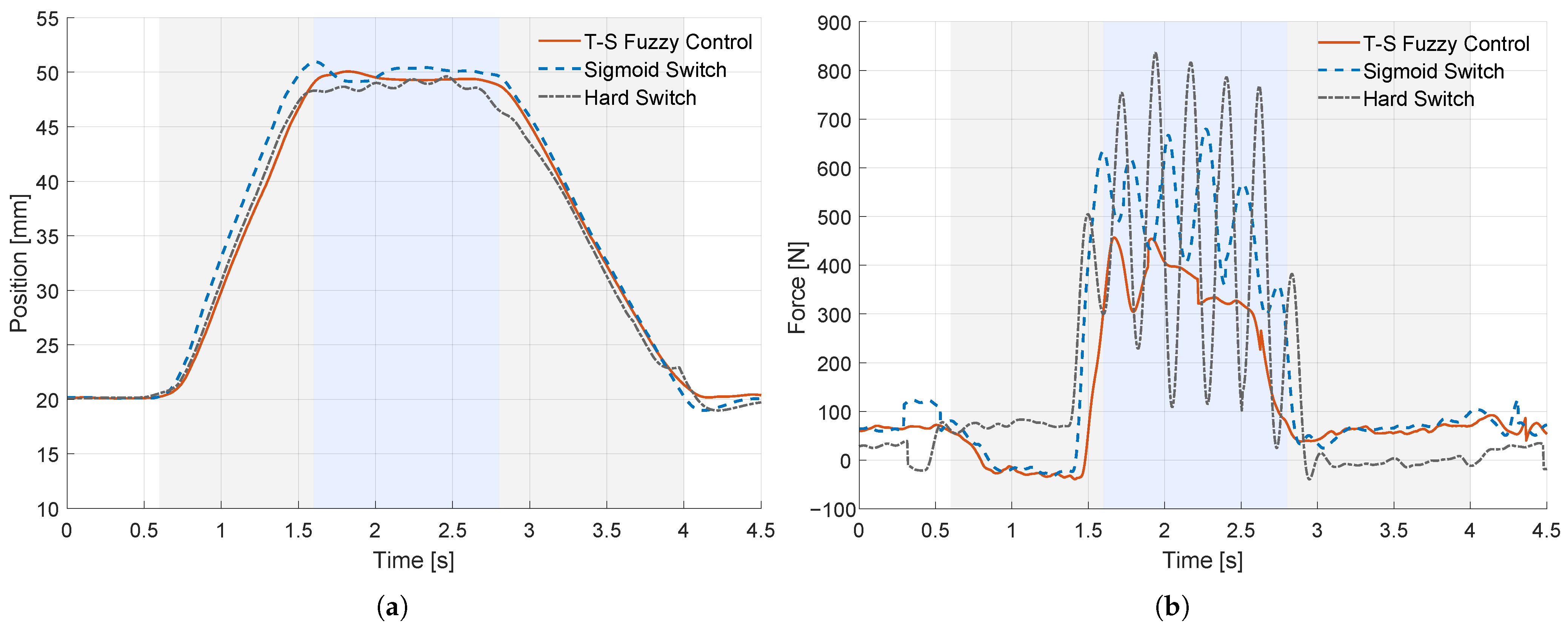
As illustrated by the blue shaded region in Figure 11, which denotes the contact duration, Figure 11b reveals distinct behaviors among the controllers. The hard-switching method exhibits severe instability, characterized by continuous rebound oscillations and excessive contact forces. While the Sigmoid-based soft-switching mitigates the peak force compared to hard-switching, it still suffers from noticeable bouncing. This is attributed to the inherent phase lag of its position-based switching threshold, which delays the controller’s reaction to the sudden impact.
Figure 11.
Comparative experimental results under dynamic impact with a rigid obstacle. The blue shaded region marks the duration of physical contact, while the gray shaded region represents the free-moving phase. Note that the proposed method significantly suppresses the peak contact force and eliminates the continuous bouncing oscillations observed in the Hard-Switching method. (a) Position tracking trajectories showing the collision and rebound behavior; (b) Estimated external contact forces during impact.
In sharp contrast, the proposed T-S fuzzy strategy rapidly stabilizes the end-effector upon contact, maintaining a stable contact state without divergence. Notably, its peak contact force is reduced by approximately 50% compared to the hard-switching benchmark. The underlying mechanism is elucidated by the valve control signals in Figure 12. The T-S controller exhibits a clean and decisive transition. Conversely, the other two methods display high-frequency chattering, indicating an inability to resolve the conflict between velocity tracking and force constraints. Comprehensive quantitative comparisons are detailed in Table 1.
Figure 12.
Control voltage signals of the four valves during the dynamic impact experiment. The blue shaded region marks the duration of physical contact, while the gray shaded region represents the free-moving phase. (a) Valve control voltage of Valve1 and Valve3; (b) Valve control voltage of Valve2 and Valve4.
6. Discussion
- A.
- Scalability to Multi-DOF and Large-Scale Systems
A primary concern regarding the applicability of the proposed method is its scalability. The proposed T-S fuzzy framework relies on physical power flow () and error dynamics () rather than absolute cylinder positions or chamber pressure. Since these premise variables are normalized within the fuzzy rules, the switching logic is inherently scalable to larger hydraulic actuators or multi-joint excavators, provided that the local controllers are tuned to the specific plant dynamics.
- B.
- Parameter Robustness and Sensitivity Analysis
The smoothness factors, and , determine the intensity of parameter variation across the switching boundaries. There is a fundamental trade-off: smaller values yield faster responses but may reintroduce the ’chattering’ phenomenon; larger values enhance stability but result in a sluggish system response.
For the experimental setup, an optimal set of parameters was selected. It is noteworthy that the two predictive premise variables (), designed based on the system’s intrinsic characteristics, can anticipate state changes to a certain extent, which endows the fuzzy control law with significant robustness in fusion. Crucially, while filters were employed during the experiments to mitigate raw data fluctuations, the controller inherently demonstrates substantial disturbance rejection against residual sensor noise and measurement errors. Consequently, the system maintains consistent performance across varying velocities and load conditions using a fixed set of smoothness factors, eliminating the need for frequent retuning on the same hardware.
- C.
- Trade-offs and Limitations
While the proposed method significantly enhances interaction stability, it involves certain trade-offs and limitations. The current framework prioritizes stability over energy regeneration. The regeneration modes were excluded from the fuzzy rules to prevent potential instability caused by active load coupling during sensitive interaction phases. However, even without regeneration, the IMS architecture inherently offers superior energy efficiency compared to conventional coupled orifice systems due to the reduction of throttling losses.
7. Conclusions
To address the system instability and chattering induced by discrete mode switching in Independent Metering Systems (IMS) during physical interaction, this paper has proposed and validated a physically-driven control framework based on the Takagi–Sugeno (T-S) fuzzy model. Different from conventional methods that rely on single-variable thresholds, this work innovatively constructs a premise space based on physical fusion variables—specifically the sliding manifold () and load power (). This design enables the controller to comprehensively reflect the system’s energy state and proactively anticipate motion trends. By designing orthogonal membership functions tailored to the IMS topology, the proposed strategy smoothly blends the local control laws, creating a continuous global control surface that fundamentally eliminates discrete jumps. Theoretically, the global asymptotic stability of the closed-loop system is rigorously guaranteed via Lyapunov analysis and LMI optimization.
Comparative experiments, including quasi-static interaction and dynamic impact tests, explicitly demonstrate the superiority of the proposed method over both hard-switching and Sigmoid-based soft-switching. Quantitative analysis reveals that, compared to hard-switching, the T-S fuzzy controller reduces the peak contact force by approximately 50%, suppresses force oscillation amplitude by over 85%, and reduces position overshoot by 90%.
In conclusion, the T-S fuzzy control strategy proposed in this paper provides a critical solution for achieving high-performance, high-stability hydraulic interaction control. By utilizing physically fused variables, it solves the inherent conflict between the discrete hardware topology and the requirement for continuous control in Human-Robot Interaction.
Future work will focus on the following key directions:
Intelligent Mode Recognition: Aiming to incorporate advanced pattern recognition to explicitly separate free-space motion from interaction tasks, this will allow the system to trigger energy regeneration modes during non-contact motion for efficiency, while reverting to the high-stability T-S fuzzy mode during interaction.
Digital Twin Validation: To verify the scalability of the framework beyond the laboratory bench, the next phase involves implementing the controller on a multi-joint manipulator using high-fidelity digital twin simulations. This will serve as a crucial validation step before field deployment in complex rescue environments.
Author Contributions
Conceptualization, Y.L. and D.C.; methodology, Y.L.; validation, Y.L.; formal analysis, Y.L.; investigation, Y.L.; resources, J.L. and D.C.; writing—original draft preparation, Y.L.; writing—review and editing, Y.L. and D.C.; visualization, Y.L.; supervision, D.C.; funding acquisition, D.C. All authors have read and agreed to the published version of the manuscript.
Funding
This research received no external funding.
Institutional Review Board Statement
Not applicable.
Informed Consent Statement
Not applicable.
Data Availability Statement
The datasets (Simulink models) presented in this article are not readily available because they are part of an ongoing study and contain proprietary control algorithms. Requests to access the datasets should be directed to hitliu1992@gmail.com.
Conflicts of Interest
The authors declare no conflicts of interest.
Appendix A. Linearized Subsystem Matrices
The local linear models are derived by linearizing the nonlinear hydraulic dynamics at the equilibrium operating points. Let the state vector be and the control input vector be .
The common system matrix structure A (for all modes, assuming nominal equilibrium volumes) is given by:
where m is the moving mass, is the viscous friction coefficient, is the effective bulk modulus. and denote the chamber volumes at the linearization point. and are the total leakage coefficients (representing inherent damping) for each chamber.The input matrices vary according to the active valve configuration in each fuzzy rule:
(1) Rule 1 (Extension-Resistive): Active valves: (Meter-in to Ch1), (Meter-out from Ch2).
(2) Rule 3 (Retraction-Resistive): Active valves: (Meter-in to Ch2), (Meter-out from Ch1).
(3) Overrunning Modes (Rules 2, 4): For overrunning conditions, the structure of the B matrices ( and ) remains similar to and respectively, assuming the same valve pairing logic is maintained.
The LMI conditions in Theorem 1 were solved using the YALMIP toolbox (Version R20250626). The physical parameters were consistent with the experimental setup. The solver successfully returned a feasible solution, confirming the existence of a common quadratic Lyapunov function. The resulting symmetric positive definite matrix P is:
References
- Delmerico, J.; Mintchev, S.; Giusti, A.; Gromov, B.; Melo, K.; Horvat, T.; Cadena, C.; Hutter, M.; Ijspeert, A.; Floreano, D.; et al. The current state and future outlook of rescue robotics. J. Field Robot. 2019, 36, 1171–1191. [Google Scholar] [CrossRef] [Scilit]
- Hogan, N. Impedance Control: An Approach to Manipulation: Part I—Theory. J. Dyn. Syst. Meas. Control 1985, 107, 1–7. [Google Scholar] [CrossRef] [Scilit]
- Raibert, M.H.; Craig, J.J. Hybrid Position/Force Control of Manipulators. J. Dyn. Syst. Meas. Control 1981, 103, 126–133. [Google Scholar] [CrossRef] [Scilit]
- Mattila, J.; Koivumäki, J.; Caldwell, D.G.; Semini, C. A Survey on Control of Hydraulic Robotic Manipulators with Projection to Future Trends. IEEE/ASME Trans. Mechatron. 2017, 22, 669–680. [Google Scholar] [CrossRef] [Scilit]
- Mattila, J.; Virvalo, T. Energy-efficient motion control of a hydraulic manipulator. In Proceedings of the 2000 ICRA. Millennium Conference. IEEE International Conference on Robotics and Automation, Symposia Proceedings (Cat. No. 00CH37065). San Francisco, CA, USA, 24–28 April 2000; Volume 3, pp. 3000–3006. [Google Scholar] [CrossRef] [Scilit]
- Ding, R.; Zhang, J.; Xu, B.; Cheng, M. Programmable hydraulic control technique in construction machinery: Status, challenges and countermeasures. Autom. Constr. 2018, 95, 172–192. [Google Scholar] [CrossRef] [Scilit]
- Abuowda, K.; Okhotnikov, I.; Noroozi, S.; Godfrey, P.; Dupac, M. A review of electrohydraulic independent metering technology. ISA Trans. 2020, 98, 364–381. [Google Scholar] [CrossRef] [Scilit]
- Murrenhoff, H.; Sgro, S.; Vukovic, M. An overview of energy saving architectures for mobile applications. In Proceedings of the 9th International Fluid Power Conference, Aachen, Germany, 24–26 March 2014; Volume 26. [Google Scholar]
- Jansson, A.; Krus, P.; Palmberg, J.O. Decoupling of response and pressure level in a hydraulic actuator. In Proceedings of the 4th Bath International Fluid Power Workshop, Bath, UK, 18–20 January 1992. [Google Scholar]
- Koivumäki, J.; Zhu, W.H.; Mattila, J. Energy-efficient and high-precision control of hydraulic robots. Control Eng. Pract. 2019, 85, 176–193. [Google Scholar] [CrossRef] [Scilit]
- Shenouda, A.; Book, W. Energy Saving Analysis Using a Four-Valve Independent Metering Configuration Controlling a Hydraulic Cylinder. In Proceedings of the SAE Commercial Vehicle Engineering Conference (COMVEC), Rosemont, IL, USA, 1–3 November 2005; SAE Technical Paper Series. SAE International: Warrendale, PA, USA, 2005. [Google Scholar] [CrossRef] [Scilit]
- Koivumäki, J.; Mattila, J. An energy-efficient high performance motion control of a hydraulic crane applying virtual decomposition control. In Proceedings of the 2013 IEEE/RSJ International Conference on Intelligent Robots and Systems, Tokyo, Japan, 3–7 November 2013; pp. 4426–4433. [Google Scholar] [CrossRef] [Scilit]
- Ketonen, M.; Linjama, M. Simulation study of a digital hydraulic independent metering valve system on an excavator. In Proceedings of the 15th Scandinavian International Conference on Fluid Power, Fluid Power in the Digital Age, SICFP’17, Linköping, Sweden, 7–9 June 2017; Linköping University Electronic Press: Göttingen, Germany, 2017; Volume 144, pp. 136–146. [Google Scholar] [CrossRef] [Scilit]
- Liu, S.; Yao, B. Coordinate Control of Energy Saving Programmable Valves. IEEE Trans. Control Syst. Technol. 2008, 16, 34–45. [Google Scholar] [CrossRef] [Scilit]
- Liu, S.; Yao, B. Energy-Saving Control of Single-Rod Hydraulic Cylinders with Programmable Valves and Improved Working Mode Selection. In Proceedings of the International Off-Highway & Powerplant Congress, Las Vegas, NV, USA, 19–21 March 2002; SAE Technical Paper Series. SAE International: Cleveland, OH, USA, 2002. [Google Scholar] [CrossRef] [Scilit]
- Shenouda, A. Quasi-Static Hydraulic Control Systems and Energy Savings Potential Using Independent Metering Four-Valve Assembly Configuration; Georgia Institute of Technology: Atlanta, GA, USA, 2006; Available online: http://hdl.handle.net/1853/11553 (accessed on 30 November 2025).
- Tabor, K.A. Optimal Velocity Control and Cavitation Prevention of a Hydraulic Actuator Using Four Valve Independent Metering. In Proceedings of the SAE Commercial Vehicle Engineering Conference (COMVEC), Chicago, IL, USA, 1–3 November 2005; SAE Technical Paper Series. SAE International: Warrendale, PA, USA, 2005. [Google Scholar] [CrossRef] [Scilit]
- Eriksson, B. Mobile Fluid Power Systems Design with a Focus on Energy Efficiency; Linkopings Universitet: Linköping, Sweden, 2010. [Google Scholar]
- Zhao, W.; Ebbesen, M.K.; Hansen, M.R.; Andersen, T.O. Mitigating Mode Switching Oscillation in a One-Motor-One-Pump Motor-Controlled Hydraulic Cylinder via System Pressure Control: Simulation Study. Energies 2024, 17, 6334. [Google Scholar] [CrossRef] [Scilit]
- Xu, B.; Ding, R.; Zhang, J.; Cheng, M.; Sun, T. Pump/valves coordinate control of the independent metering system for mobile machinery. Autom. Constr. 2015, 57, 98–111. [Google Scholar] [CrossRef] [Scilit]
- Ding, R.; Xu, B.; Zhang, J.; Cheng, M. Bumpless mode switch of independent metering fluid power system for mobile machinery. Autom. Constr. 2016, 68, 52–64. [Google Scholar] [CrossRef] [Scilit]
- Lyu, L.; Chen, Z.; Yao, B. Energy Saving Motion Control of Independent Metering Valves and Pump Combined Hydraulic System. IEEE/ASME Trans. Mechatron. 2019, 24, 1909–1920. [Google Scholar] [CrossRef] [Scilit]
- Yang, J.; Li, J.; Zhong, Y.; Gao, Y.; Guo, R.; Zhao, J. Research on Design and Control Strategy of Novel Independent Metering System. Sustainability 2023, 15, 13359. [Google Scholar] [CrossRef] [Scilit]
- Nguyen, T.H.; Do, T.C.; Nguyen, V.H.; Ahn, K.K. High Tracking Control for a New Independent Metering Valve System Using Velocity-Load Feedforward and Position Feedback Methods. Appl. Sci. 2022, 12, 9827. [Google Scholar] [CrossRef] [Scilit]
- Hu, S.; Wang, L.; Li, Y.; Zhang, L. Variable Universe Fuzzy Controller for an Independent Metering System of Construction Machinery. Processes 2023, 11, 901. [Google Scholar] [CrossRef] [Scilit]
- Meng, W.; Lutang, L.; Aihong, W.; Hong, R.; Youshan, G. Multiple quadrants displacement tracking control of independent metering electro-hydraulic system. Sci. Rep. 2024, 14, 21951. [Google Scholar] [CrossRef] [Scilit]
- Junxiang, C.; Hongda, J.; Xiangdong, K.; Chao, A. Research on Smoothness of Mode Switch of Independent Metering Systems Considering Time-delay Factors. China Mech. Eng. 2025, 36, 414–425. [Google Scholar]
- Li, L.; Qian, J.; Zou, Y.; Tian, D.; Zeng, Y.; Cao, F.; Li, X. Optimized Takagi–Sugeno Fuzzy Mixed H2/H∞ Robust Controller Design Based on CPSOGSA Optimization Algorithm for Hydraulic Turbine Governing System. Energies 2022, 15, 4771. [Google Scholar] [CrossRef] [Scilit]
- Wang, Y.; Zou, L.; Ma, L.; Zhao, Z.; Guo, J. A survey on control for Takagi-Sugeno fuzzy systems subject to engineering-oriented complexities. Syst. Sci. Control Eng. 2021, 9, 334–349. [Google Scholar] [CrossRef] [Scilit]
- Ksantini, M.; Ellouze, A.; Delmotte, F. Control of a hydraulic system by means of a fuzzy approach. Int. J. Optim. Control Theor. Appl. (IJOCTA) 2013, 3, 121–131. [Google Scholar] [CrossRef] [Scilit]
- Kumar, P.S.; Sivakumar, K.; Kanagarajan, R.; Kuberan, S. Adaptive Neuro Fuzzy Inference System control of active suspension system with actuator dynamics. J. Vibroengineering 2018, 20, 541–549. [Google Scholar] [CrossRef] [Scilit]
- Kolks, D.I.G.; Weber, I.J. Modiciency-Efficient industrial hydraulic drives through independent metering using optimal operating modes. In Proceedings of the 10th International Fluid Power Conference, Dresden, Germany, 8–10 March 2016; Available online: https://nbn-resolving.org/urn:nbn:de:bsz:14-qucosa-199423 (accessed on 30 November 2025).


Disclaimer/Publisher’s Note: The statements, opinions and data contained in all publications are solely those of the individual author(s) and contributor(s) and not of MDPI and/or the editor(s). MDPI and/or the editor(s) disclaim responsibility for any injury to people or property resulting from any ideas, methods, instructions or products referred to in the content. |
© 2026 by the authors. Licensee MDPI, Basel, Switzerland. This article is an open access article distributed under the terms and conditions of the Creative Commons Attribution (CC BY) license.