


Abstract
Spaceflight has become more accessible than ever due to increased launch reliability and significant advances in electronics. Among these advancements are small-sized PocketQubes, which are small satellites (5 × 5 × 5 cm for 1P) that can be built using commercial off-the-shelf components. A critical subsystem in these satellites is the communication system, which requires compact and deployable antennas. This work focuses on the design of deployable antennas for TU Delft’s upcoming Delfi-Twin PocketQube mission, operating in the 10 m and 6 m amateur bands. The Shape Memory Alloy (SMA) nitinol was selected as the antenna material due to its favorable mechanical and deployment characteristics. However, its high electrical resistivity limits antenna efficiency. This study investigates multiple conductive coating techniques for nitinol antenna wires, aiming to improve electrical performance while maintaining mechanical flexibility. The coatings are evaluated through electrical resistance measurements and mechanical bending tests. Among them, a DuPont ME164 ink showed the most promising performance, significantly reducing wire resistance compared to bare nitinol while preserving mechanical integrity. These results address a novel conductive coating for efficient SMA-based antennas and demonstrate a valid approach for improving deployable antennas in small-satellite applications.
1. Introduction
Throughout recent decades, spaceflight has become much more accessible through increased launch reliability and advances in electronics. At the end of the 20th century, advances in microelectronics allowed satellites to be built in smaller form factors than ever before [1]. However, despite these advancements, small corporations and universities still face significant challenges in developing and launching satellites due to expensive parts and launch costs.
In 1999, with the introduction of the CubeSat standard by Puig-Suari and Twiggs at California Polytechnic State University, spaceflight became more accessible to small corporations and universities [2]. Puig-Suari and Twiggs specified that a one standard unit (U) is a 10 × 10 × 10 cm cube which weighs 1.33 kg.
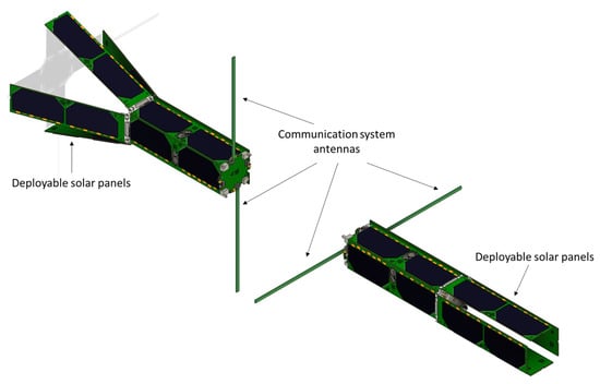
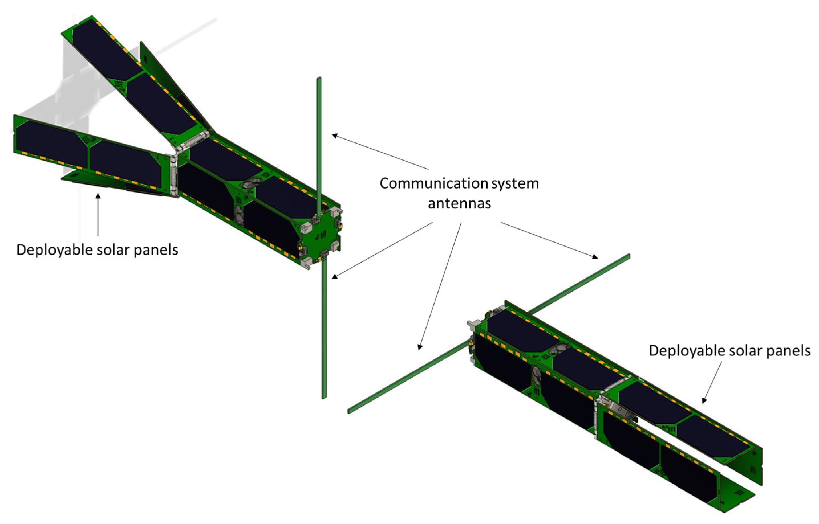
Due to the immense success of CubeSat, Robert J. Twiggs proposed the development of the PocketQube in 2009 [3]. Like CubeSat, PocketQubes can be stacked to form larger units, but their dimensions are reduced by half, with a standard unit (1P) measuring just 5 × 5 × 5 cm, with a weight of 250 gr [4]. TU Delft has developed a series of CubeSats and PocketQubes as part of the Delfi program, starting with Delfi-C3 (in 2008) [5], followed by Delfi-Next [6] and Delfi-PQ [7]. The next step is to launch a pair of 3P PocketQube satellites, called Delfi-Twin [1] (Figure 1). The mission of the latter is to demonstrate formation flying and relative navigation for small satellites, while conducting various measurements in low Earth orbit [8]. One of the payloads aboard both satellites of Delfi-Twin is the RABSII instrument [9] (Radio Amateur Beacons aboard a nano-Satellite for the Investigation of the Ionosphere). This monitoring system will focus on the ionosphere, specifically a phenomenon known as sporadic E [9].
Figure 1.
Delfi-Twin PocketQube setup.
The ionosphere is a layer of the upper atmosphere which is ionized by solar radiation. This layer has an impact on radio propagation by reflecting, refracting, and scattering radio signals [10]. One of these effects is linked to sporadic E, a temporary ionospheric radio propagation reflection phenomenon with a low prediction probability [11]. sporadic E can create interference for low-power communication devices and broadcasting services [9]. By better studying and understanding the formation of sporadic E, its effects and potential interference when transmitting radio signals can be mitigated. There have been attempts made to try and study sporadic E at higher frequencies, but these suffer from errors such as refraction, temperature errors and water vapors [9]. TU Delft’s next PocketQube, Delfi-Twin, housing the RABSII instrument, will try to study sporadic E at much lower frequencies, namely 28 MHz and 50 MHz. Therefore, RABSII will be installed operating on one satellite at 28 MHz, while on the other satellite at 50 MHz. To be able to transmit at these lower frequencies from a PocketQube platform, the antenna system must be deployable due to size constraints. Additionally, these platforms only generate a limited amount of power. Hence, a miniaturized and highly efficient antenna setup is needed aboard both PocketQubes.
The aim of this research is to select the material for a compact and highly efficient antenna system, compatible with the volume restriction of Delfi-Twin. The material selection of the antenna is studied, leading to the use of a Shape Memory Alloy (SMA) and specifically nitinol. This wire comes with its limitations, specifically its high resistive value. To overcome this limitation, the application of a highly conductive coating is a potential solution. Although several coating techniques are already used in space [12,13,14,15], the coating of antennas for space-based applications has only been applied in limited cases [16,17], especially SMA coatings [18,19,20]. Mostly, coatings are applied onto larger surfaces. They play a crucial role across numerous fields such as corrosion protection, surface functionalization, encapsulation, electronics, including OLEDs, electroluminescent devices, photovoltaics, EMI shielding and touch sensors. Besides electronics, in the medical sector, coatings are applied via additive manufacturing to provide components with biocompatibility for use inside the human body [21]. In this research, several coating techniques are investigated to reduce the resistive losses of nitinol when used as an antenna wire for space applications. The conductivity achieved depends on factors such as the coating thickness, the ink composition and the curing technique. Optimizing conductivity directly enhances the efficiency of the transmitted radio signal. Since radio-frequency (RF) applications deal with high frequencies, the skin effect further increases the importance of the coating for antenna performance [22,23,24]. Finally, because the antenna wire will be folded within the limited containment of the Delfi-Twin PocketQube, the coating must withstand bending to a radii of about 2 mm without loss of performance and conformity.
2. Antenna Design Limitations and Material Selection
2.1. Design Limitations
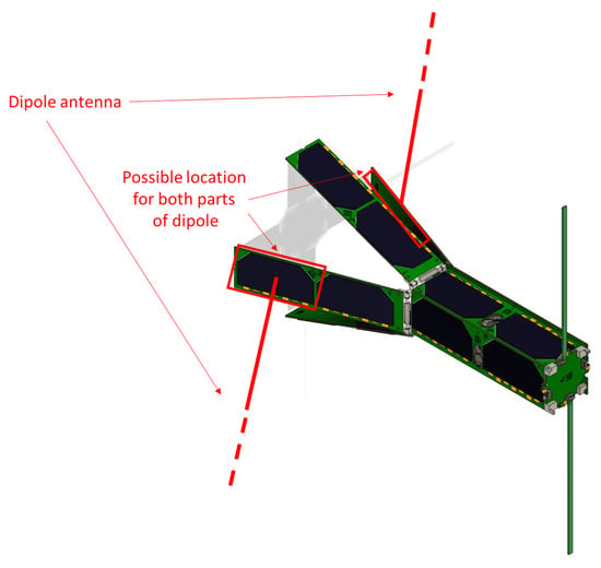
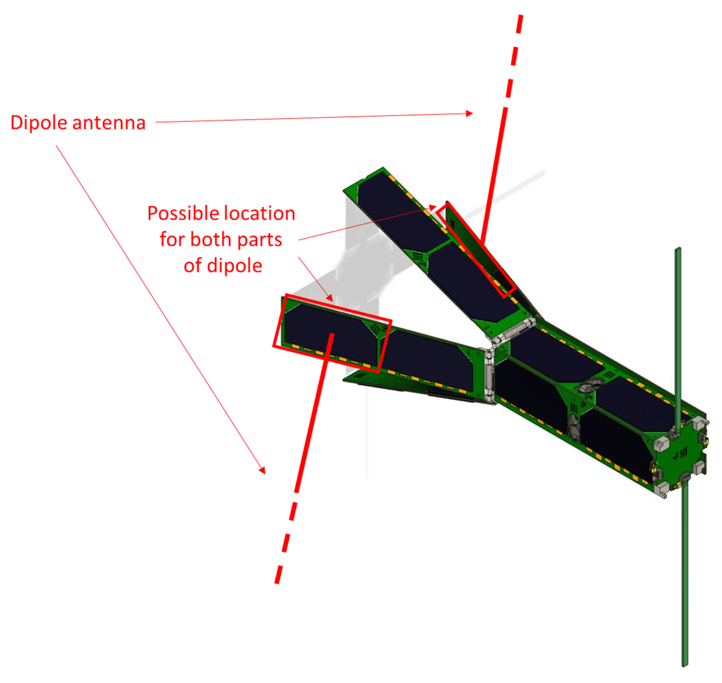
Considering the use of the PocketQube standard as the baseline to fit a 28 MHz and 50 MHz antenna, several design constraints are imposed on the deployable antenna systems on both satellites. The system must fit within the dimensional constraints of the Delfi-Twin PocketQube. Due to having a maximum number of solar panels mounted on all sides of the satellite and its deployable solar panels (Figure 1), only limited space is available for the antenna system. Two half-panels are potentially available to house the antenna system, with dimensions 8 × 4 × 0.2 cm (Figure 2).
Figure 2.
Possible location of both parts of the dipole on the satellite panels.
Due to this low available volume to store the antenna, the integration of complex deployable antennas is not possible. Hence, the basic dipole antenna [25] was chosen as the baseline for the 28 MHz, as well as for the 50 MHz frequency. The simplicity of this antenna, being just two wires, lowers the deployment risk and increases the reliability of the antenna system.
For the frequencies of 28 and 50 MHz, the corresponding wavelengths (λ) are 10 m and 6 m, respectively. With the calculated wavelength, the total dipole length L (=λ/2) is 5 m for the 28 MHz frequency, with each wire element measuring 2.5 m. For 50 MHz, the dipole length L is 3 m, with each element measuring 1.5 m. Each element of the antenna itself is woven in a zig-zag pattern onto each panel. These wires should fit into the volume described above. Hence, the thickness of the wires is limited to only a few tenths of a millimeter.
Additionally, the 3P Delfi-Twin PocketQube has a limited weight of only 750 gr. In this frame, the antenna system should also not exceed a weight of 60 g.
2.2. Antenna Material Selection
To store this long wire into the aforementioned volume, a Shape Memory Alloy (SMA) was selected, namely nitinol. These are metallic alloys with the unique property to change shape with the influence of temperature [26,27]. SMAs were already used in space, like on the ALBus CubeSat [28], the NASA Mars Pathfinder [29], and on MightySat-1 [30].
SMAs have two different phases, each with their own unique crystal structure inside the alloy creating different properties. One phase is the high-temperature phase called austenite (A). When the alloy cools down to a low temperature, it will transform into its other phase, called martensite (M). The crystal structure between these two states is different. The transformation inside the crystal structure occurs by lattice distortion, which means that the atoms move away from their ideal structure. The transformation from an ideal, mostly cubic crystal structure to the lattice distortion that can be found in the martensite phase is called martensitic transformation [26].
There are many different combinations of alloys that are used to make SMAs. All these different alloys have different characteristics. The combination of different metals results in different melting points and different strengths. One of these important factors is the E modulus or Young’s modulus, which measures the stiffness of the material and represents its ability to resist deformation under tensile or compressive stress. A higher E modulus indicates a stiffer material, whereas a lower value suggests more flexibility. Some combinations of different metals result in a less dense alloy that could be helpful in applications where a lightweight alloy is needed, such as medical applications [27]. The different alloys result in different temperatures of martensite and austenite. In this way, SMAs can be designed to have different operating temperatures for different scenarios [26].
Due to their excellent characteristics, Ni–Ti, Cu–Ni–Al, and Cu–Zn–Al are often used. Ni-Ti or nitinol is very ductile and can tolerate high strains and is very corrosion-resistant. The Cu-based alloys have a wider range of transformation temperatures and the Cu– Zn–Al alloys have a much higher damping capacity [27].
Nitinol is readily available in different austenite finish temperatures (Af) and sizes [26]. By training the nitinol to remain straight above its Af temperature, applying heat would allow it to transform into a straight line, which is in-line with the shape of a dipole antenna. Fortunately, many nitinol wires are factory-trained to adopt this specific shape, meaning that the wire would already be preconfigured for the desired straight-line structure. To deploy the nitinol antenna, a heat source must be applied to raise the wire’s temperature above its Af temperature. Fortunately, the sun radiates approximately 1366 W/m2 in Earth’s orbit [31] and hence can serve as the heat source to deploy the antenna. In previous missions, TU Delft observed high temperatures of around 80 °C on the surface of their Delfi-PQ satellite due to this solar radiation [32]. If the Af temperature of the nitinol wire is set below 80 °C, the sun’s radiation can naturally heat the wire to the required temperature, thereby deploying the dipole antenna.
2.3. Nitinol Resistivity
One challenge with using nitinol wire as an antenna is its relatively high electrical resistance compared to conventional antenna materials such as copper, silver, or gold. For instance, nitinol has an electrical resistivity of approximately 1.10 × 10⁻⁶ Ωm, whereas copper has a much lower resistivity of about 1.68 × 10⁻⁸ Ωm [33]. This significant difference means that nitinol will impose more electrical resistance if used as an antenna, leading to reduced efficiency. Higher electrical resistance causes more transmission energy to be lost along the wire, rather than being effectively radiated. A way to mitigate this increased electrical resistance is to apply a low-resistivity coating onto the nitinol wire. Several coating techniques already exist [34,35,36,37], but they are not intensively used to coat nitinol. Possible coating techniques which lower the electrical resistivity value of nitinol are discussed in Section 3.
3. Nitinol Coating Results
In order to make the nitinol wire more efficient in the frame of antenna use, a second more conductive layer (e.g., for example copper, silver, or gold) can be placed on top of the nitinol wire. This coating layer can serve as an effective antenna due to the skin effect. The skin effect is a frequency-dependent phenomenon in which Alternating Current (AC) tends to concentrate near the surface of a conductive material like a wire rather than distributing evenly throughout its cross-section [38,39]. As a result, the current density is greatest at the outer surface and diminishes exponentially with increasing depth into the material. The skin depth is defined as the depth at which the current density is around 37% of its value at the surface of the material [38,39]. This depth δ depends on the frequency f of the AC signal, as well as the conductor’s electrical resistivity ρ, the relative magnetic permeability μr, and the vacuum permeability μ0 [39]:
For gold, ρ is 2.24 μΩcm, μr is 1, and μ0 is 4π × 10−7 H/m [33], which at 28 MHz leads to a skin depth of 14.24 μm.
3.1. Electroplated Coating
A problem with nitinol coatings is that both nickel and titanium are known for their challenging adhesion properties. The first test to coat the nitinol used a method called electroplating. Electroplating is a process that uses electrical current to deposit a thin layer of metal onto the surface of another material [40]. The basic setup involves two electrodes: an anode and a cathode immersed in an electrolyte bath containing a solution of metal salts. The anode is typically made of the metal that will form the coating (for example, copper or nickel), while the cathode is the object to be plated. When a direct current is applied, metal ions from the anode dissolve into the electrolyte and are attracted to the negatively charged cathode. There, the metal ions are reduced and deposited onto the surface, forming a uniform metal layer [41].
Due to the difficult nature of the substrate, unconventional etching solutions were used. The best results were achieved by immersing the material for 30 s in a bath of concentrated nitric acid (37 wt%) diluted 10 times (resulting in 3.7 wt%), with the addition of 3 wt% sodium fluoride.
After rinsing, the substrate was immersed in a nickel strike. Strikes are nonconventional electroplating solutions typically used for challenging substrates [42]. Among these, nickel strikes are the most used, and given the presence of nickel in the alloy, this seemed the most logical choice. An alternative could have been a copper strike, but these are based on cyanide baths, which should preferably be avoided [43]. The composition of the nickel strike bath was as follows: 100 g/L HCl and 200 g/L nickel chloride with a current density of 5–15 A/dm2. The anodes were nickel plates and the temperature of the bath was around 20–30 °C. The nitinol was submerged for about 5 min.
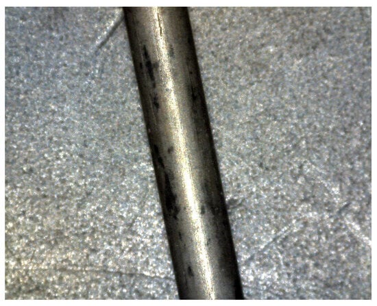
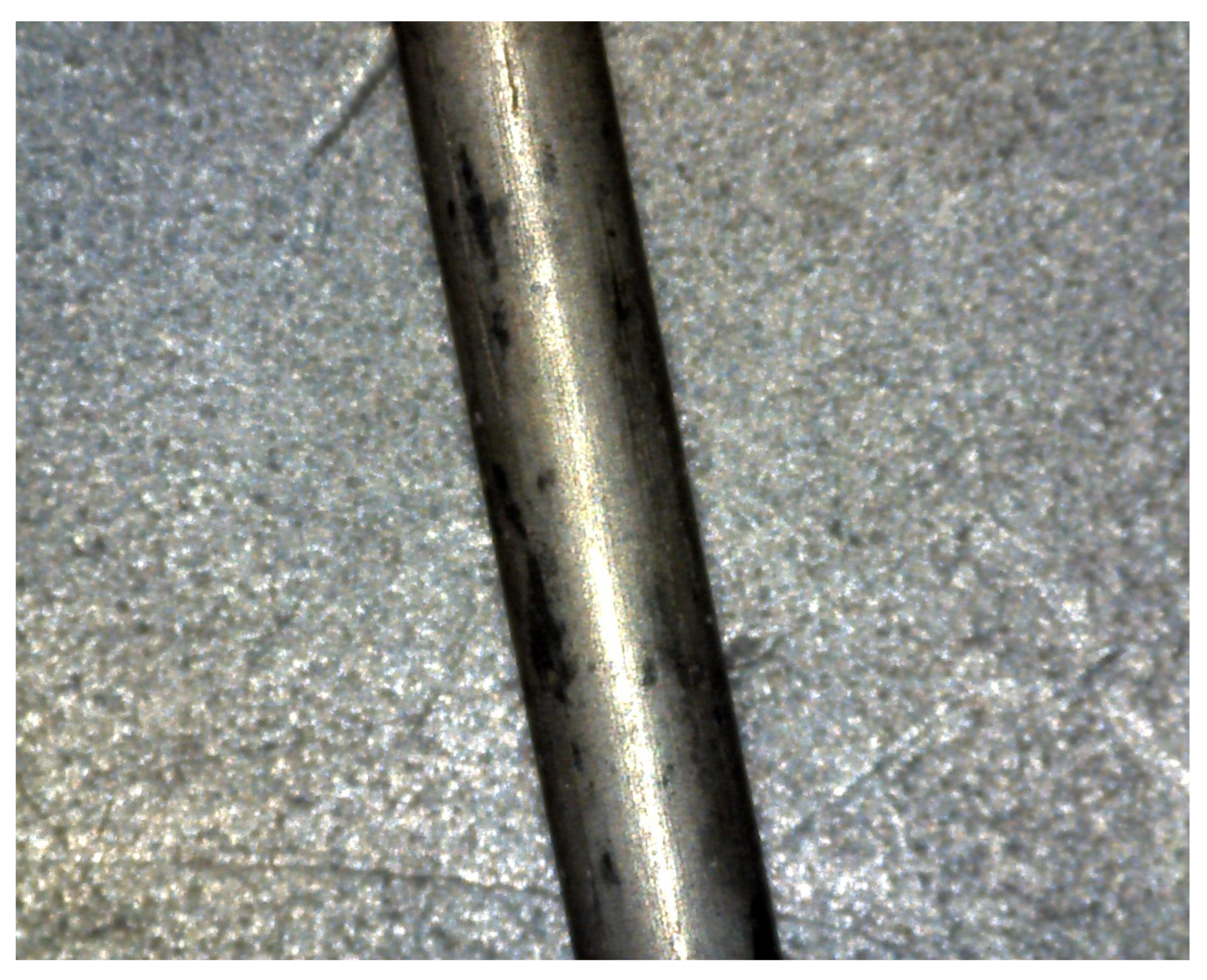
The results of this coating method were unsatisfactory and can be seen in Figure 3, as the plating on the nitinol wire was not uniform. This is largely due to the inherent difficulty of achieving strong adhesion between the coating material and the nitinol surface. Even when nickel, which is an element already present in the nitinol alloy, was used, the coating did not adhere well and appeared very thin. A resistance measurement was performed on both the coated and uncoated nitinol samples. The results showed no significant difference between the two, confirming that the coating was not uniformly applied. The minimal thickness of the coating was also thin. Therefore, an alternative coating method must be explored to achieve a more reliable and effective result.
Figure 3.
Electroplated nitinol. Result shows a non-uniform plating.
3.2. Ultrasonic Spray Coating
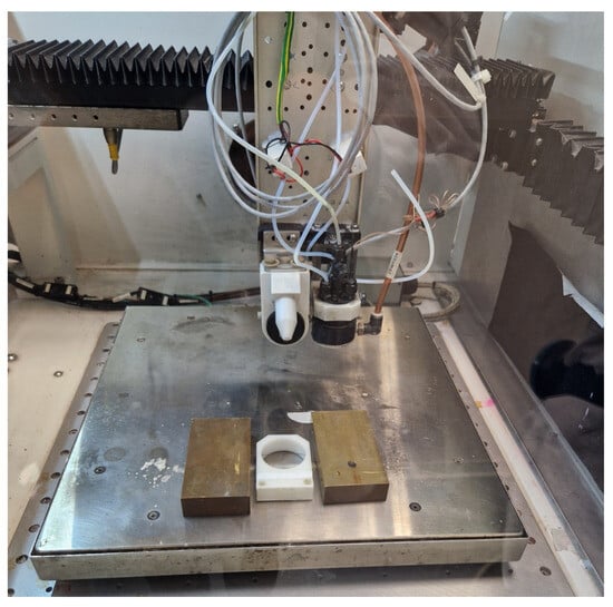
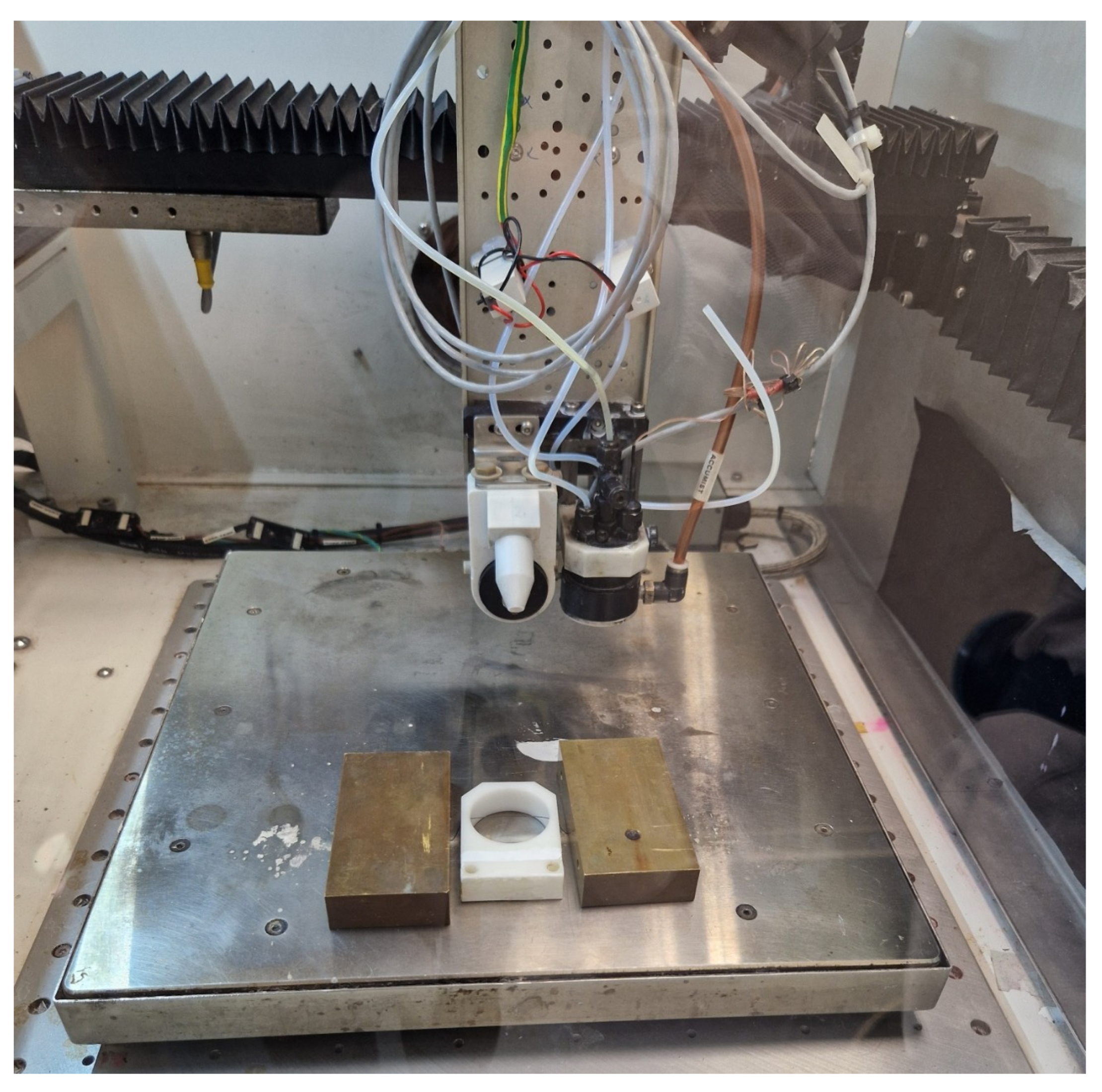
The initial test utilized a particle-free self-reducing silver (Ag) ink solution. In this solution, the Ag atoms are structured in a chemical complex. Upon curing in an oven, the complex evaporates, leaving behind only the silver [44]. The ink was applied using a Sono-Tek ExactaCoat ultrasonic spray coater, using an accumist precision nozzle (Sono-Tek Corporation, Milton, NY, USA). Approximately 10 cm of 0.3 mm diameter nitinol wire was used for testing. Prior to coating, the wire was cleaned in an ultrasonic bath containing isopropanol. It was then suspended horizontally above the hotplate of the sprayer, allowing the shroud gas to assist in evenly distributing the ink around the wire during application (Figure 4).
Figure 4.
Test setup for spray coating.
The first test was done to see how the spray deposits on the nitinol wire. A nozzle traverse speed of 100 mm/s and a nozzle-to-wire distance of 20 mm were maintained throughout the process. A flow rate of 0.4 mL/min was used, with a 10 s delay between layers to allow partial drying. This process was repeated for 10 layers. A lower flow rate means a less-thick coating, so a second test was performed using a higher flow rate of 0.6 mL/min and a longer delay time of 20 s. Again, 10 layers were applied. However, this configuration resulted in droplet formation at the bottom of the wire, likely due to insufficient proximity to the heated bed, which prevented efficient drying. As a compromise, a third configuration was selected: a flow rate of 0.5 mL/min with a 20 s delay time. Due to the thin nature of each sprayed layer, a program was developed to apply 100 layers in total. After 100 layers, the wire was cured in an oven at around 130 °C. After curing, a visual inspection revealed that the coating remained very thin and was non-uniform, particularly between the top and bottom sides of the nitinol wire. The wire resistance decreased marginally, from 0.290 Ω/cm to 0.281 Ω/cm.
3.3. Dip Coating
The second coating technique which was explored was dip coating using different Ag-based inks typically employed in metal screen printing [45,46,47]. Two different types of ink were employed. The first was a nanoparticle-based silver ink, characterized by a minimal amount of binder and a high concentration of silver nanoparticles. Upon sintering, this type of ink yields bulk-like silver layers with excellent electrical conductivity but limited flexibility, stretchability, and in some cases limited adhesion properties. The second ink type was a microflake ink consisting of silver microflakes (usually within the range of 0.5 to 5 micrometers) dispersed within a polymeric binder. In these inks, the flakes form percolation paths, while the binder provides mechanical stability and adhesion. Silver microflake inks exhibit lower conductivity compared to silver nanoparticle inks, but their composition can be tuned to achieve an optimal balance between conductivity, stretchability, and flexibility for specific applications.
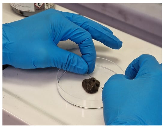
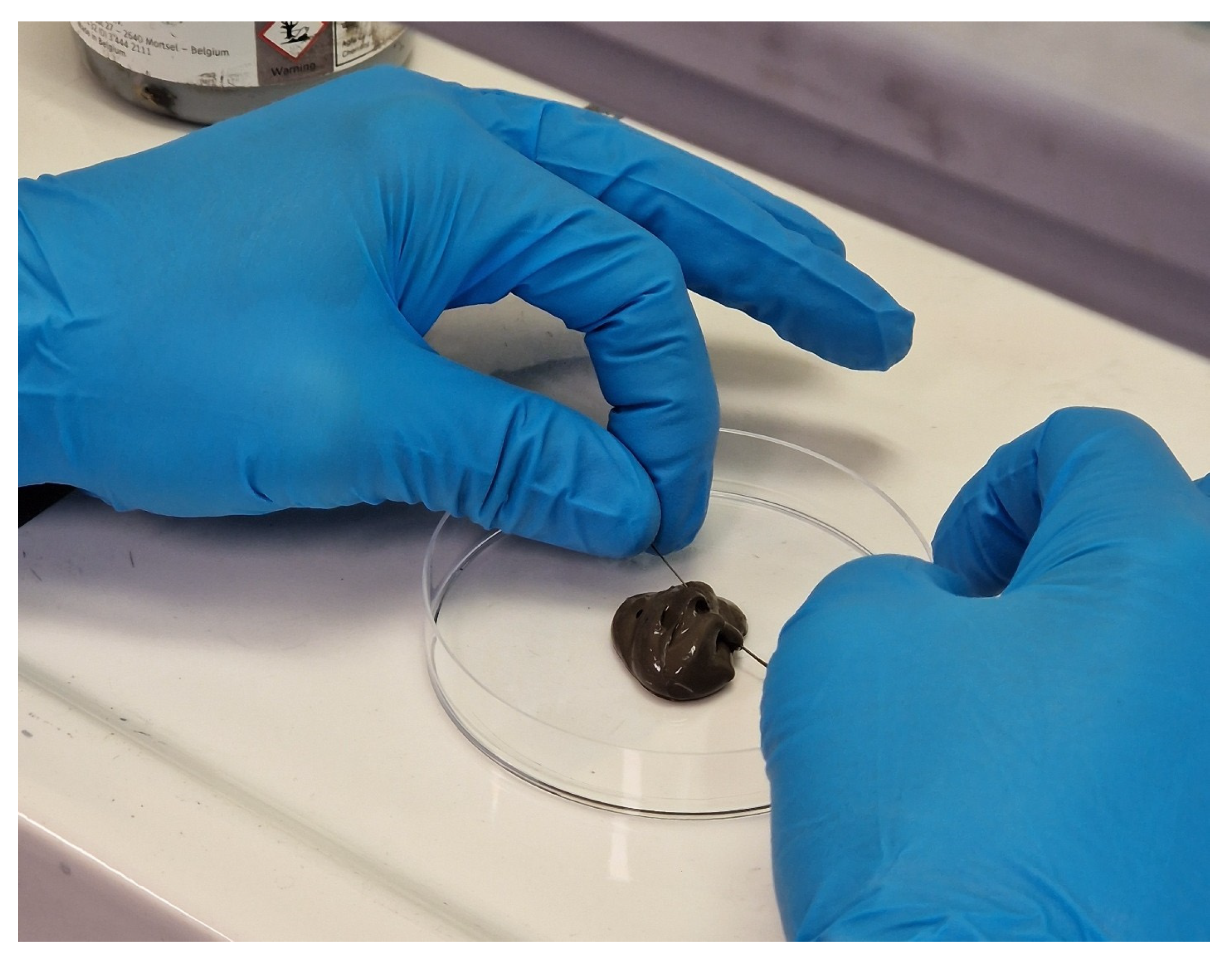
A small volume of ink was put in a recipient, while the nitinol wire was fed through the ink in an attempt to achieve a uniform coating (see Figure 5). All samples consisted of 10 cm long, 0.3 mm diameter nitinol wires, which were first cleaned in an ultrasonic bath of isopropanol.
Figure 5.
Manual dip coating proof of principle.
The first ink tested was Orgacon SIP2000 provided by Agfa (Agfa-Gevaert Group, Mortsel, Belgium), a nanoparticle-based ink containing silver particles ranging in size from 30 to 100 nm, with a solid content of 65 to 70 wt%. Three samples were prepared by guiding the wire through the SIP2000 ink. Due to the ink’s shear-thinning properties, it exhibited high viscosity at rest but became less viscous (2–3 Pa s) at the wire interface, under shear stress as the wire moved through it. This effect enabled the formation of a relatively uniform coating on the wire surface. To ensure coating uniformity, the withdrawal speed was kept constant for all samples.
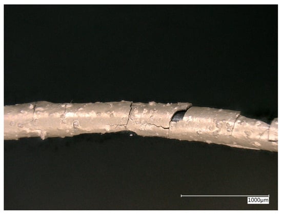
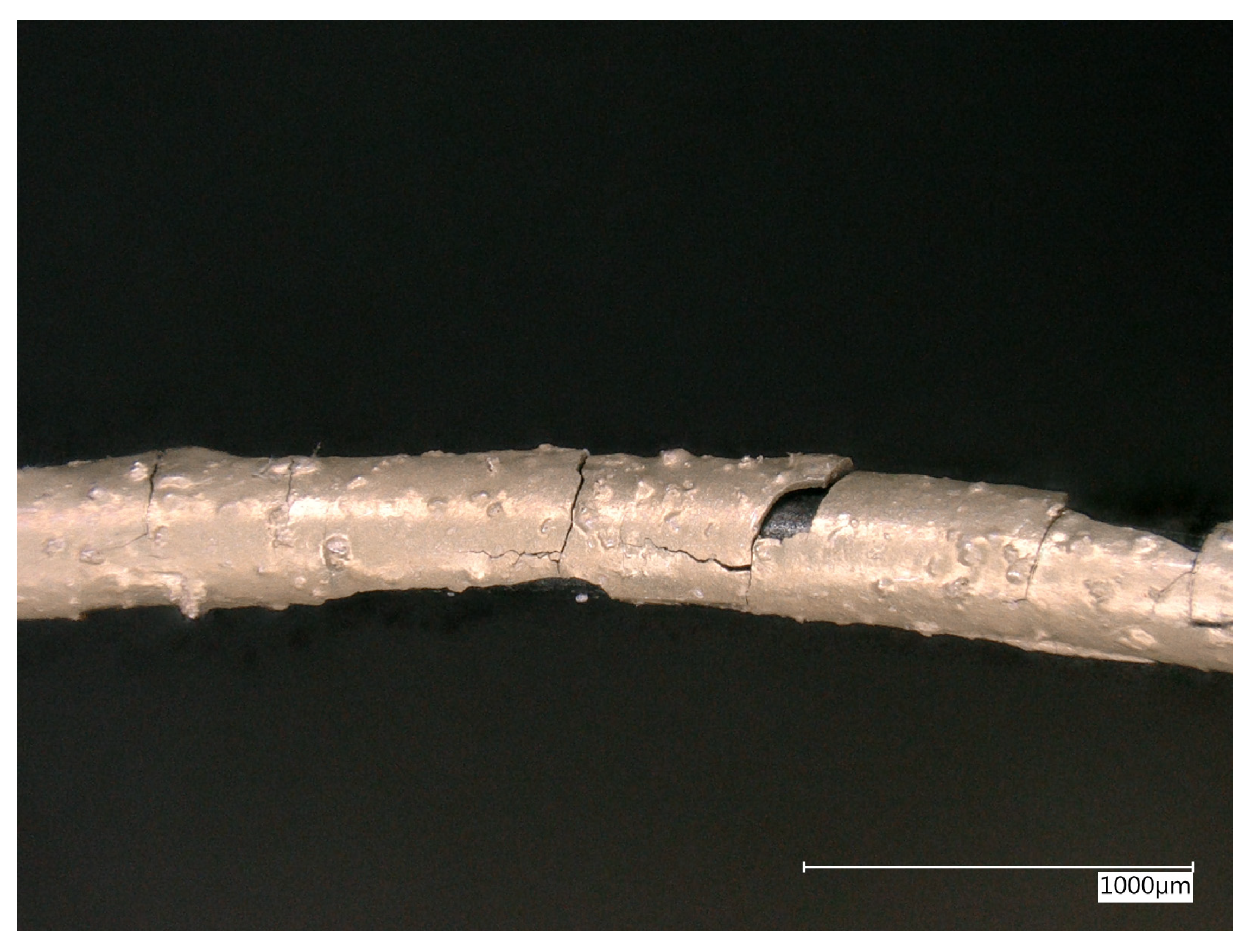
To investigate the effect of curing conditions on the coating, each sample was subjected to a different thermal treatment: the first sample was placed in a VWR dryline DL56 oven (VWR, Leuven, Belgium) at 130 °C for around 15 min, the second sample was placed in the oven at around 150 °C for around 15 min, and the final sample was placed in the oven at around 130 °C for 45 min. The wire’s electrical resistance reduced from 0.290 Ω/cm for the uncoated nitinol wire, to 0.075 Ω/cm (74% decrease), 0.042 Ω/cm (86% decrease), and 0.021 Ω/cm (92.8% decrease), respectively. An initial mechanical test was performed by bending the coated wires to observe how the coating responded to deformation. For this test, a Solvica cylindrical mandrel tester (Solvica B.V., Dronten, The Netherlands) with a mandrel diameter of 2 mm was used in accordance with ASTM D522 [48]. As the SMA wire is intended to deploy only once in space, the bend test was performed as a one-time evaluation rather than a cyclic fatigue test. The selected 2 mm mandrel, however, represents a more severe bending condition than the maximum bend radius when folded in its actual application, thereby providing a conservative assessment of the coating adhesion. In all three cases, the coating cracked and detached from the wire surface (Figure 6). Microscopic inspection confirmed the presence of cracks, which are undesirable as they compromise both the mechanical integrity and electrical conductivity of the coating. The poor adhesion strength in combination with limited flexibility comes from the fact that this ink is optimized for screen printing on polymer substrates, on which the adhesion properties are well-matched and result in excellent conductivity and flexibility. In contrast, metals like nitinol are known to exhibit poor adhesion with other metallic coatings, which explains the behavior observed in this case.
Figure 6.
SIP2000 bending test shows the cracked coating detaching from the wire surface.
Additionally, the coatings exhibited surface irregularities, with visible bumps and inconsistencies visible under the microscope (Figure 7). This was because the ink was only hand stirred and thus not properly homogenized prior to application. Using a SpeedMixer (Romaco BV, Oud-Beijerland, The Netherlands), which mixes the ink at high rotational speeds, could resolve the inconsistencies by producing a smoother, more uniform ink mixture.
Figure 7.
SIP2000 coating texture showing surface irregularities, with visible bumps and inconsistencies.
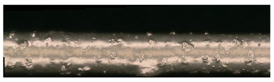
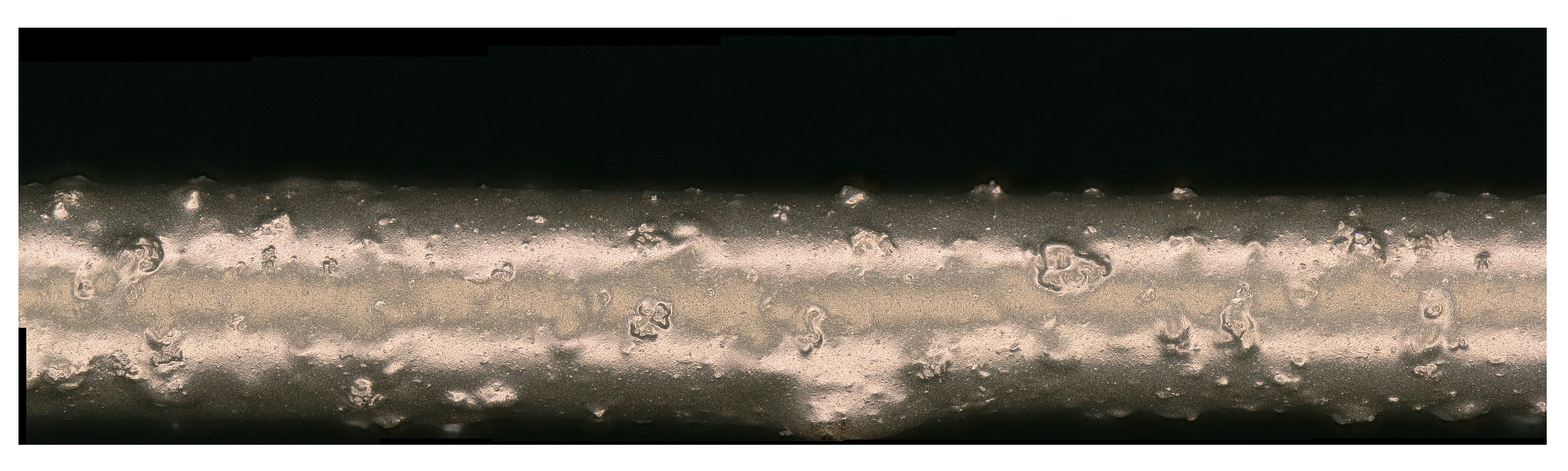
The next two samples were prepared using a microflake ink. This type of ink can, as explained earlier, potentially mitigate the adhesion issue since the polymer binder has a greater affinity for nitinol surfaces, albeit at the expense of electrical conductivity. The inks employed were DuPont ME164 (DuPont, Mechelen, Belgium) and ECI 1501 silver inks (Henkel Belgium S.A., Brussels, Belgium), both designed to provide greater elasticity compared to Agfa Orgacon SIP2000. These formulations are based on silver micro particles ranging from 0.5 to 10 μm in size, dispersed in a polymer binder, both with a solid content of around 70 wt%. However, both inks presented challenges during the coating process. Unlike Orgacon SIP2000 (Agfa-Gevaert Group, Mortsel, Belgium), these inks have a significantly higher viscosity (10–40 Pa s) and lack shear-thinning behavior. As a result, the ink tended to adhere more heavily to the wire surface, leading to uneven coatings with visibly thicker patches in certain areas (Figure 8). After coating, both samples were cured in an oven at 130 °C. The resistance decreased relatively equally, starting from the reference resistance of 0.290 Ω/cm, towards 0.063 Ω/cm (78% reduction) for DuPont ME614 and 0.051 Ω/cm (82% reduction) for Henkel ECI 1501, taking into account the coating thicknesses of 108 and 118 µm, respectively). The wires were then bent and examined under a microscope (Figure 8). Neither sample showed any cracking upon bending, indicating improved mechanical flexibility compared to the nanoparticle-based Orgacon SIP2000-coated wires. Additionally, the coatings appeared smooth and free of surface bumps, thanks to proper ink homogenization using a SpeedMixer prior (Romaco BV, Oud-Beijerland, The Netherlands) to application.
Figure 8.
DuPont ME164 bend test leading to uneven coatings with visibly thicker patches in certain areas.
To improve coating uniformity and mitigate the issues observed with the previous samples, an additional test was conducted using a diluted version of the DuPont ME164 ink. A thinned ink solution was prepared by mixing the ink with acetone in a 1:2 volume ratio (ink:solvent), resulting in an effective solid content of approximately 23–24 wt%. This modified solution significantly enhanced the coating process, allowing the ink to flow more easily over the wire and producing a more uniform layer. The coated wire was then cured, bent, and examined with an optical microscope (Figure 9). As expected, the coating thickness reduced in accordance with the dilution, leading to a corresponding reduction in wire resistance of 26% relative to the uncoated wire, yielding a resistance of 0.215 Ω/cm. The inspection revealed no visible cracks. As expected, the coating appeared noticeably thinner than previous samples. This is attributed to the lower viscosity of the diluted ink solution, which allowed it to spread more evenly and form a more uniform layer on the wire surface.
Figure 9.
Diluted DuPont ME164 bend test showing no visible cracks.
3.4. Wire Drawing
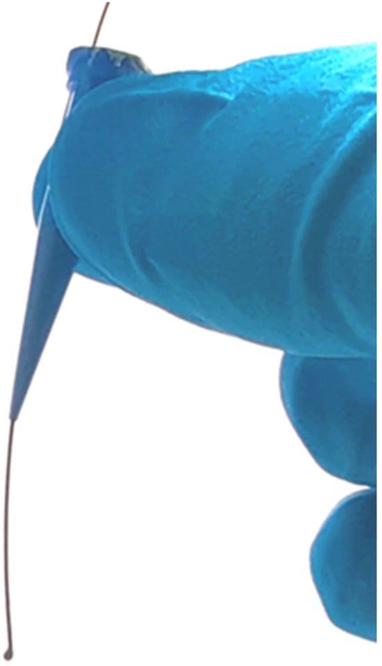
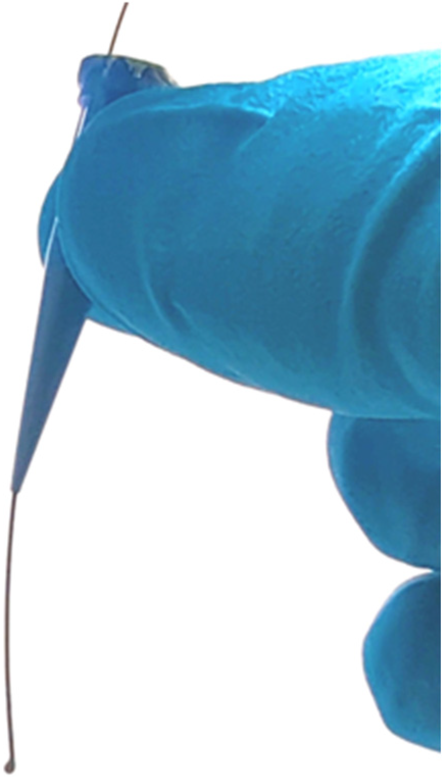
To increase the coating uniformity of the microflake ink, the conventional dip-coating method was adapted into a wire-drawing method as earlier reported by G. Holesinger et al. [49]. In this method, the wire is still dipped and pulled through the ink solution; however, a die forces the ink to stay within a defined form shape at the pullout point. By doing so, the die limits and homogenizes the deposited ink layer on the nitinol wire. The die used in this experiment had a long conical section towards the exit point, generating shear forces that naturally aligned the wire with the center of the orifice, thereby producing a uniform coating thickness around the wire circumference. The die used in this research was a Nordson PTFE precision tip with an orifice opening of 400 µm.
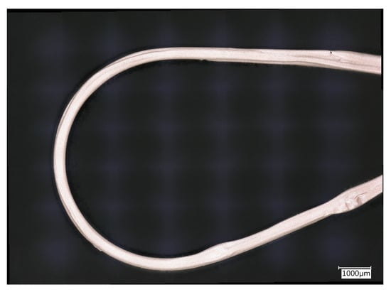
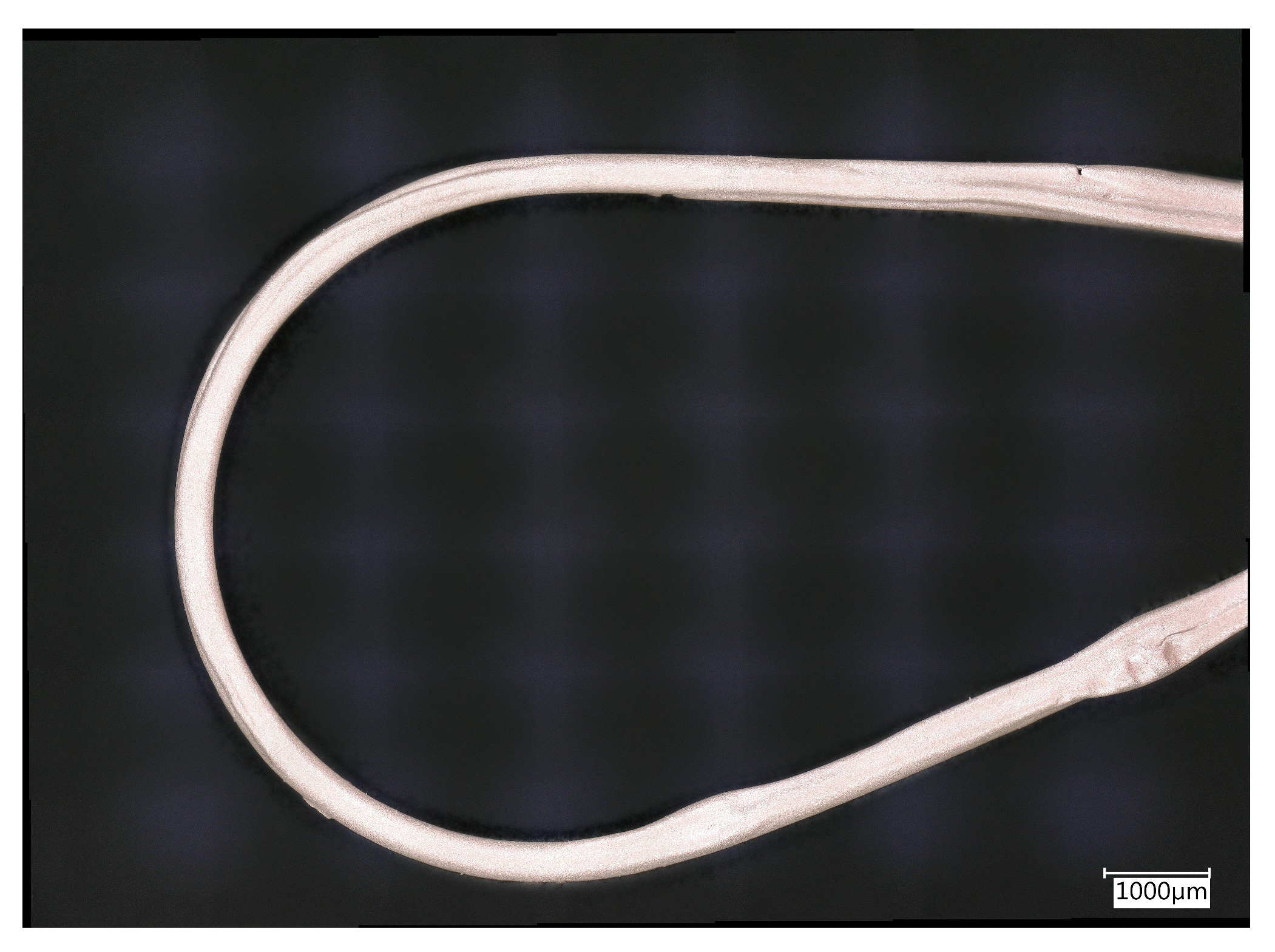
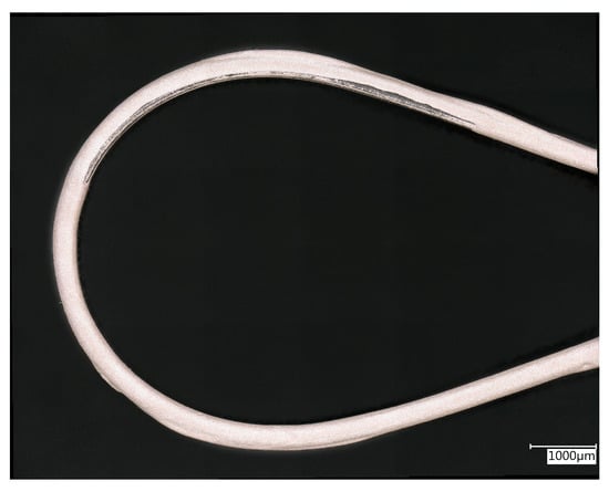
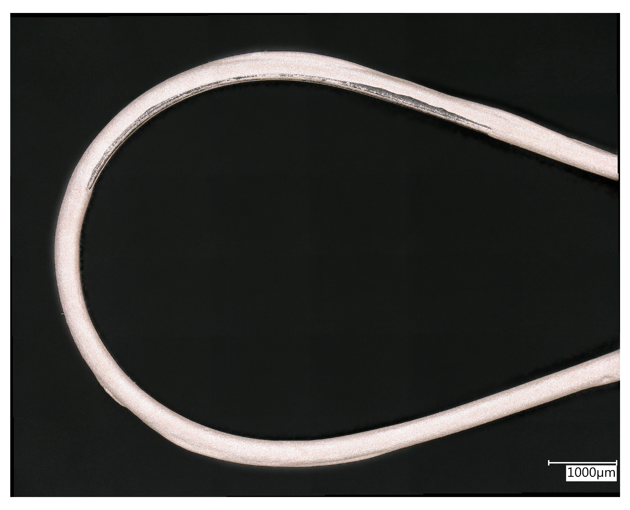
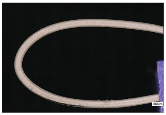
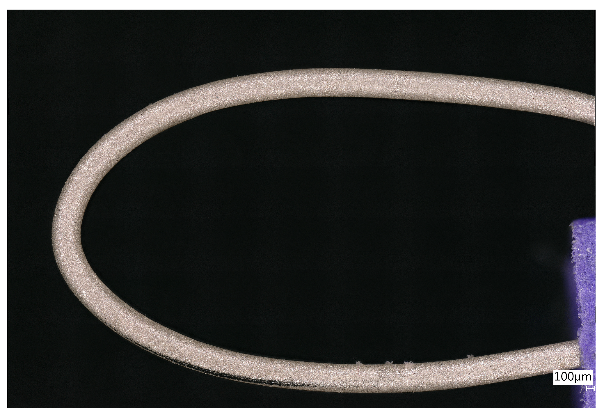
In Figure 10, the Nordson PTFE precision tip is filled with DuPont ME614 silver flake ink. A 300 µm nitinol wire is manually drawn through the 400 µm tip opening, resulting in a very homogeneous coating, excluding the first few millimeters when advancing towards the regime condition. The samples were cured at 120 °C for 15 min. After curing, the wire resistance dropped to 0.106 Ω/cm (63% reduction). Optical inspection, as shown in Figure 11, demonstrates excellent homogeneity of the coating along the length of the nitinol antenna wire, as well as its strong adhesion during bending. Furthermore, optical inspection suggests a lower surface roughness compared to dip-coated samples, which can be important for antenna applications at high frequencies in which the skin effect plays a significant role.
Figure 10.
Wire-drawing process, coating a 300 µm nitinol wire with ME614 ink, through a precision pipette tip with an orifice of 400 µm.
Figure 11.
Wire-drawn DuPont ME164 bend test showing excellent homogeneity of the coating along the length of the wire.
4. Discussion
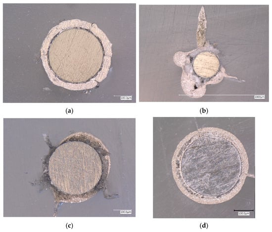
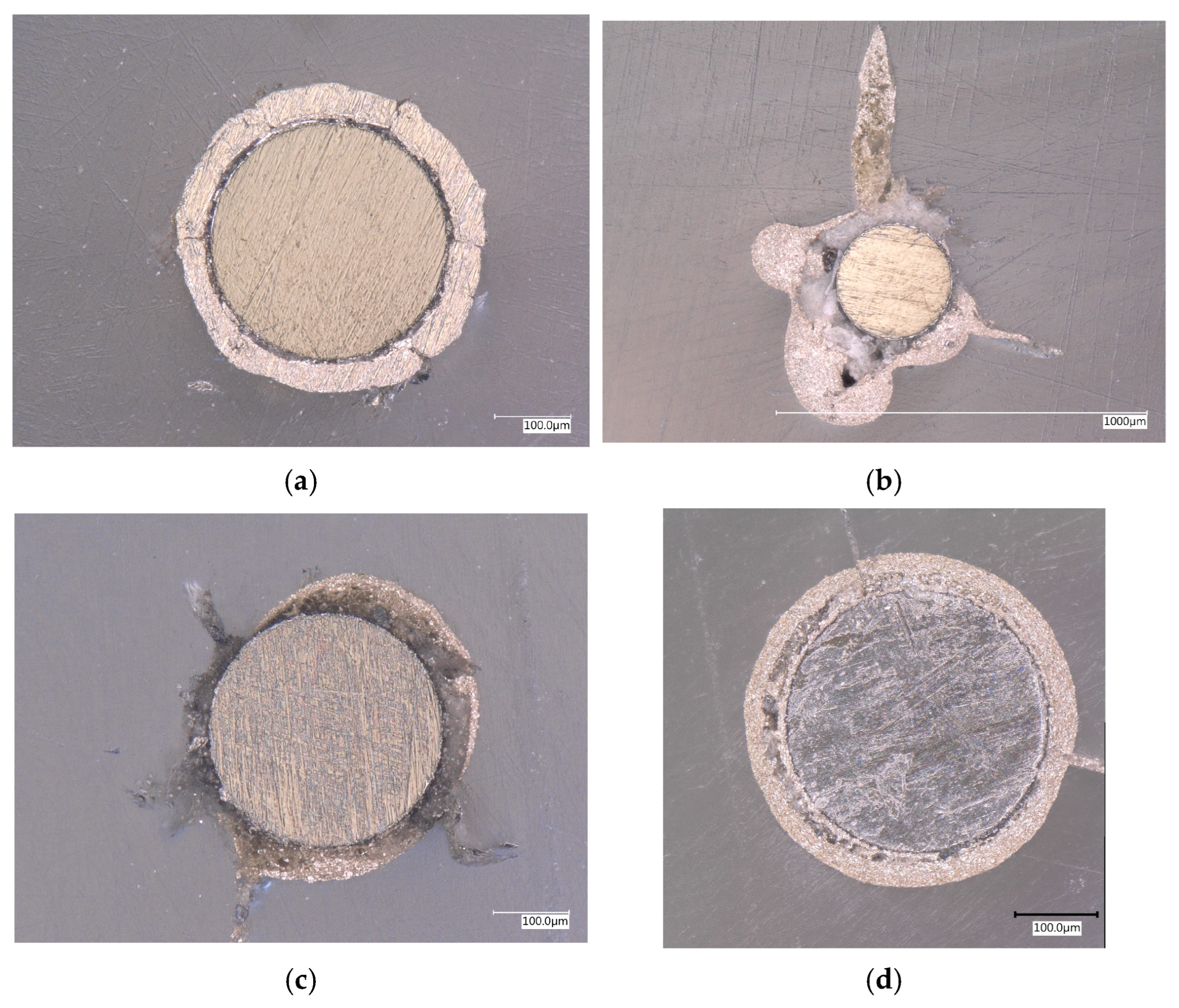
To evaluate the electrical performance of the different coatings the direct current (DC) resistance was measured on all samples produced by both spraying and dip coating methods. The coating thickness for each sample was determined by examining the cross-section of the wire under a microscope (Figure 12). To create cross-sectional specimen, the wire is embedded in a clear epoxy resin, cured for 48 h and polished, as earlier explained in Section 3.
Figure 12.
(a) Cross-sectional view of a dip-coated nitinol wire with Agfa Orgacon SIP2000. The 300 µmø nitinol wire is coated with a ±50 µm thick silver layer after sintering; (b) Cross-sectional view of a dip-coated nitinol wire with DuPont ME614. The 300 µmø nitinol wire is coated with a very non-uniform layer of silver ink; (c) Cross-sectional view of a dip-coated nitinol wire with the diluted version of DuPont ME614. The 300 µmø nitinol wire is coated with a relatively non-uniform layer of silver ink; (d) Cross-sectional view of a wire-drawn coated nitinol wire with DuPont ME614. The 300 µmø nitinol wire is coated with a uniform layer of silver ink.
The resistance is measured using a HP 34401A Multimeter in four wire configurations to measure the average wire resistance over 10 cm, eliminating probe contact resistances. In Table 1, an overview is given of the different coating techniques and their accompanying coating thickness and wire resistance per centimeter of antenna wire.
Table 1.
DC resistance measurement results for different samples.
The results indicate that the coating thickness, the ink composition and the curing parameters have a significant influence on the resistance of the coating. The sample coated using the particle-free self-reducing ink via spraying exhibited an extremely thin coating, resulting in no measurable difference in resistance compared to uncoated nitinol wire. In contrast, the samples coated with SIP2000, DuPont ME164 and ECI 1501, each of which produced thicker layers, demonstrated a notable reduction in resistance due to improved electrical conductivity from the thicker silver coatings. The sample coated with the diluted DuPont ME164 ink displayed a thinner layer compared to the non-diluted version, which led to slightly higher resistance. The notable difference in conductivity between SIP2000 and ME614 comes from the intrinsic difference in ink type; nanoparticle versus microflake, respectively, as earlier described. Finally, prolonged curing or sintering reduces the resistance of the coating until the intrinsic limit of the ink is reached.
5. Conclusions
A conclusion can be made from these initial tests on coatings for nitinol wire. All samples retained their shape memory effect, demonstrating that the coating processes did not hinder the functional properties of the material, in particular, post-curing or sintering of the ink must retain below the austenite finish temperature (Af) to preserve the shape memory effect. Among the tested methods, the manual wire-drawn DuPont ME164 ink showed the most promising results, offering ease of application, outstanding coating homogeneity and strong mechanical flexibility under bending. Wire drawing offers the highest controllability and can therefore be considered for future automation, enabling adjustable nozzle diameters (coating thickness), tunable coating speed, and controlled curing temperature. This approach would allow optimization of the coating thickness, resistance, surface roughness, and homogeneity for specific applications.
The scope of the present work is limited to evaluating the improvement in electrical conductivity of coated SMA wires through resistance measurements, alongside an assessment of their mechanical bending performance. As such, the full-scale RF performance of antennas manufactured from the coated SMA wires is beyond the scope of this paper. Future work will therefore focus on a RF characterization of the most promising coating solutions identified in this study. This will include measurements of antenna input impedance, radiation efficiency, bandwidth, and radiation patterns at the target operating frequencies in the 10 m and 6 m amateur bands. In addition, the impact of the coating on RF losses under dynamic deployment conditions can be part of future work. Further research will also address the long-term reliability aspects relevant to space missions, such as thermal cycling, vacuum compatibility, and potential degradation of the coating under space environmental conditions. These efforts will enable a complete assessment of coated SMA-based deployable antennas and support their qualification for future small-satellite missions.
Author Contributions
Conceptualization, J.V., R.J. and D.R.; methodology, R.J. and D.R.; validation, J.V., R.J., D.R. and W.D.; formal analysis, J.V., R.J., D.R. and W.D.; investigation, J.V., R.J., D.R. and W.D.; resources, D.R. and W.D.; data curation, R.J., D.R. and W.D.; writing—original draft preparation, J.V. and R.J.,; writing—review and editing, J.V., R.J., D.R. and W.D.; visualization, J.V. and D.R.; supervision, J.V. and D.R.; project administration, J.V., D.R. and W.D.; funding acquisition, D.R. and W.D. All authors have read and agreed to the published version of the manuscript.
Funding
This research received no external funding.
Data Availability Statement
The original contributions presented in the study are included in the article, further inquiries can be directed to the corresponding author.
Acknowledgments
The authors thank all participants in the study. Special thanks go to IMO/IMOMEC for their willingness to conduct all coating tests.
Conflicts of Interest
The authors declare no conflicts of interest.
Abbreviations
The following abbreviations are used in this manuscript:
| AC | Alternating Current |
| DC | Direct Current |
| RABSII | Radio Amateur Beacons Aboard a Nano-Satellite for the Investigation of the Ionosphere |
| RF | Radio-Frequency |
| SMA | Shape Memory Alloy |
References
- Balasubramanian, M.; Srimath, R.; Vignesh, L.; Rajesh, S. Application of Shape Memory Alloys in Engineering—A Review. J. Phys. Conf. Ser. 2021, 2054, 012078. [Google Scholar] [CrossRef] [Scilit]
- Laufer, R.; Pelton, J.N. The Smallest Classes of Small Satellites Including Femtosats, Picosats, Nanosats, and CubeSats; Springer International Publishing: Cham, Switzerland, 2019; pp. 87–101. [Google Scholar]
- Owen, A.; Zack, K.; Jernigan, J.G.; Twiggs, B.J.; Cominsky, L.R.; Malphrus, B.K.; Silverman, B.; McNeil, S.; Roach-Barrette, W. The PocketQube T-LogoQube: A Prototype Approach for Future Space-Based Astronomy Experiments. In Proceedings of the American Astronomical Society, AAS Meeting #224, Boston, MA, USA, 1–5 June 2014; Volume 224, pp. 122–123. [Google Scholar]
- Bouwmeester, J.; Radu, S.; Uludag, M.S.; Chronas, N.; Speretta, S.; Menicucci, A.; Gill, E.K.A. Utility and Constraints of PocketQubes. CEAS Space J. 2020, 12, 573–586. [Google Scholar] [CrossRef] [Scilit]
- Ubbels, W.J.; Hamann, R.J.; Verhoeven, C.J.M.; Bonnema, A.R.; van Breukelen, E.D. Delfi-C3: A Student Nanosatellite as a Test-Bed for Thin Film Solar Cells and Wireless Onboard Communication. In Proceedings of 2nd International Conference on Recent Advances in Space Technologies; Kurnaz, S., Ince, F., Onbasioglu, S., Basturk, F., Eds.; IEEE: Istanbul, Turkey, 2005; pp. 167–172. [Google Scholar]
- Bouwmeester, J.; Brouwer, G.F.; Gill, E.K.A.; Monna, G.L.E.; Rotteveel, J. Design Status of the Delfi-Next Nanosatellite Project. In Proceedings of the 61st International Astronautical Congress, Prague, Czech Republic, 27 September–1 October 2010; International Astronautical Federation: Prague, Czech Republic, 2010. [Google Scholar]
- Radu, S.; Uludag, S.; Speretta, S.; Bouwmeester, J.; Gill, E.; Chronas Foteinakis, N. Delfi-PQ: The First PocketQube of Delft University of Technology. In 69th International Astronautical Congress, Bremen, Germany, 1–5 October 2018; IAF: Bremen, Germany, 2018. [Google Scholar]
- Gill, E.; Leijtens, J.; de Milliano, M.; Aas, C. Delfi-Twin: A Formation Flying Mission Concept. In 3rd International Symposium on Formation Flying, Missions and Technologies, Noordwijk, The Netherlands, 23–25 April 2008; ESA: Noordwijk, The Netherlands, 2008; pp. 1–6. [Google Scholar]
- Vanhamel, J.; Berwaerts, M.; Speretta, S.; Uludag, S. Concept of Sporadic E Monitoring Using Space-Based Low Power Multiple Beacon Systems. Atmosphere 2024, 15, 1306. [Google Scholar] [CrossRef] [Scilit]
- Schunk, R.W.; Nagy, A.F. Ionospheres: Physics, Plasma Physics, and Chemistry, 2nd ed.; Cambridge University Press: New York, NY, USA, 2009. [Google Scholar]
- Whitehead, J.D. Recent Work on Mid-Latitude and Equatorial Sporadic-E. J. Atmos. Terr. Phys. 1989, 51, 401–424. [Google Scholar] [CrossRef] [Scilit]
- Clergereaux, R.; Orlandi, V.; Kahn, M.; Navarro, G.; Paillet, A. Coatings for Space-Based Systems: Impacts of Plasma Processes. In Proceedings of the 52nd International Conference on Environmental Systems, Calgary, AB, Canada, 16–20 July 2023. [Google Scholar]
- Fan, X.; Xue, Q.; Wang, L. Carbon-based solid-liquid lubricating coatings for space applications-A review. Friction 2015, 3, 191–207. [Google Scholar] [CrossRef] [Scilit]
- Hołyńska, M.; Tighe, A.; Semprimoschnig, C. Coatings and thin films for spacecraft thermo-optical and related functional applications. Adv. Mater. Interfaces 2018, 5, 1701644. [Google Scholar] [CrossRef] [Scilit]
- Ince, J.C.; Peerzada, M.; Mathews, L.D.; Pai, A.R.; Al-Qatatsheh, A.; Abbasi, S.; Yin, Y.; Hameed, N.; Duffy, A.R.; Lau, A.K.; et al. Overview of emerging hybrid and composite materials for space applications. Adv. Compos. Hybrid Mater. 2023, 6, 130. [Google Scholar] [CrossRef] [Scilit]
- Li, M.J.; Li, M.; Liu, Y.F.; Geng, X.Y.; Li, Y.Y. A review on the development of spaceborne membrane antennas. Space Sci. Technol. 2022, 2022, 9803603. [Google Scholar] [CrossRef] [Scilit]
- Vertegaal, C.; Bentum, M. Feasibility Study of Inflatable Antennas as Observational Antenna for Ultra Low Frequency CubeSat Applications. In Proceedings of the 2020 IEEE Aerospace Conference, Big Sky, MT, USA, 7–14 March 2020. [Google Scholar]
- Viscuso, S.; Gualandris, S.; de Ceglia, G.; Visentin, V. Shape memory alloys for space applications. In Shape Memory Alloy Engineering; Butterworth-Heinemann: Oxford, UK, 2021; pp. 609–623. [Google Scholar]
- Ulmer, M.P.; Jalilvand, M.; Marks, N.A.; Buchholz, D.B.; Fujishima, B.; Guerra, N.; Cao, J.; Chung, Y.-W.; Baturalp, T.B.; Coverstone, V.L.; et al. The prospects for applying magnetic smart materials combined with shape memory alloys to produce correctable and deployable space telescopes. In Advances in Optical and Mechanical Technologies for Telescopes and Instrumentation IV; SPIE: Bellingham, WA, USA, 2020; pp. 393–404. [Google Scholar]
- Vertegaal, C.; Bentum, M.; Pourshaghaghi, H.R. Using Shape Memory Alloy for CubeSat Antenna Design in Space. In 2021 15th European Conference on Antennas and Propagation (EuCAP), Dusseldorf, Germany, 22–26 March 2021; IEEE: New York, NY, USA, 2021; pp. 1–5. [Google Scholar]
- Saylor, D.M.; Sivan, S.; Turner, P.; Shi, H.; Soneson, J.E.; Weaver, J.D.; Di Prima, M.; Sussman, E.M. Temperature Dependence of Nickel Ion Release from Nitinol Medical Devices. J. Biomed. Mater. Res. B Appl. Biomater. 2021, 109, 1188–1197. [Google Scholar] [CrossRef] [Scilit] [PubMed]
- Iwashita, Y. Reduction of RF Power Loss Caused by Skin Effect. In Proceedings of the LINAC 2004, Lübeck, Germany, 16–20 August 2004. [Google Scholar]
- Dai, S.; He, Y.; Huang, H.; Zhang, H.; Zhang, J.; Peng, Y.; Bai, F. Electrodeposited CoCu/Cu Meta-Conductor with Suppressed Skin Effect for Next Generation Radio Frequency Electronics. J. Alloys Compd. 2019, 778, 156–162. [Google Scholar] [CrossRef] [Scilit]
- Guo, C.; Wu, P.; Liu, Y.; Fan, T. Radio-Frequency Conductivity Evaluation Method Based on Surface/Interface Scattering of Metallic Coatings. Coatings 2024, 14, 599. [Google Scholar] [CrossRef] [Scilit]
- Xiao, B.; Wong, H.; Li, M.; Wang, B.; Yeung, K.L. Dipole Antenna with Both Odd and Even Modes Excited and Tuned. IEEE Trans. Antennas Propag. 2022, 70, 1643–1652. [Google Scholar] [CrossRef] [Scilit]
- Lagoudas, D.C. Shape Memory Alloys: Modeling and Engineering Applications; Springer: Boston, MA, USA, 2008; Chapter 1. [Google Scholar]
- Prasad, N.E.; Wanhill, R.J.H. Aerospace Materials and Material Technologies, Volume 1: Aerospace Materials; Springer: Singapore, 2016; Chapter 21. [Google Scholar]
- Sadhukhan, D.; Guzik, A.; Benafan, O.; Boukabou, I.; Tomko, B.; Sorrells, M.; Fabanich, W. Advanced Electrical Bus (ALBus) CubeSat: From Build to Flight. In Proceedings of the 34th Annual Small Satellite Conference, Logan, UT, USA, 1–6 August 2020. [Google Scholar]
- Matijevic, J.; Shirley, D. The Mission and Operation of the Mars Pathfinder Microrover. Control Eng. Pract. 1997, 5, 827–835. [Google Scholar] [CrossRef] [Scilit]
- Kramer, H.J.; Cracknell, A.P. An Overview of Small Satellites in Remote Sensing. Int. J. Remote Sens. 2008, 29, 4285–4337. [Google Scholar] [CrossRef] [Scilit]
- Boxwell, M. Solar Electricity Handbook: A Simple, Practical Guide to Solar Energy; Greenstream Publishing: Coventry, UK, 2012. [Google Scholar]
- Uludağ, M.; Speretta, S.; Bouwmeester, J.; Gill, E.; Perez-Soriano, T. A New Electrical Power System Architecture for Delfi-PQ. In Proceedings of the 4th IAA Conference on University Satellite Missions and CubeSat Workshop, Rome, Italy, 4–7 December 2017. [Google Scholar]
- Cutnell, J.D.; Johnson, K.W. Physics, 4th ed.; Wiley: New York, NY, USA, 1998; p. 591. [Google Scholar]
- Marchal, W.; Vandevenne, G.; D’Haen, J.; Calmont de Andrade Almeida, A.; Durand Sola, M.A.; van den Ham, E.J.; Drijkoningen, J.; Elen, K.; Deferme, W.; Van Bael, M.K.; et al. Ultrasonically Spray Coated Silver Layers from Designed Precursor Inks for Flexible Electronics. Nanotechnology 2017, 28, 215202. [Google Scholar] [CrossRef] [Scilit]
- Stryckers, J.; Swusten, T.; Brullot, W.; D’Haen, J.; Verbiest, T.; Deferme, W. Ultrasonic Spray Coating as a Fast Alternative Technique for the Deposition of Hybrid Magnetic–Plasmonic Nanocomposites. Adv. Eng. Mater. 2018, 20, 1800681. [Google Scholar] [CrossRef] [Scilit]
- Mirri, F.; Ma, A.W.K.; Hsu, T.T.; Behabtu, N.; Eichmann, S.L.; Young, C.C.; Tsentalovich, D.E.; Pasquali, M. High-Performance Carbon Nanotube Transparent Conductive Films by Scalable Dip Coating. ACS Nano 2012, 6, 9737–9744. [Google Scholar] [CrossRef] [Scilit]
- Ojstršek, A.; Jug, L.; Plohl, O. A Review of Electroconductive Textiles Utilizing the Dip-Coating Technique: Their Functionality, Durability, and Sustainability. Polymers 2022, 14, 4713. [Google Scholar] [CrossRef] [Scilit]
- Fink, D.G.; Beaty, H.W. Standard Handbook for Electrical Engineers, 16th ed.; McGraw-Hill: New York, NY, USA, 2013. [Google Scholar]
- Jordan, E.C. Electromagnetic Waves and Radiating Systems; Prentice Hall: Englewood Cliffs, NJ, USA, 1968; p. 130. [Google Scholar]
- Chen, H.; Liao, F.; Yuan, Z.; Han, X.; Xu, C. Simple and Fast Fabrication of Conductive Silver Coatings on Carbon Fabrics via an Electroless Plating Technique. Mater. Lett. 2017, 196, 205–208. [Google Scholar] [CrossRef] [Scilit]
- Sha, W.; Wu, X.; Keong, K.G. Electroless Copper and Nickel–Phosphorus Plating: Processing, Characterisation and Modelling; Woodhead Publishing: Cambridge, UK, 2011. [Google Scholar]
- Kato, T.; Terashima, H.; Watanabe, H.; Watanabe, M.; Honma, H.; Takai, O. Influence of Complexing Agents in Electroless Nickel Strike Plating Solution for Solder Ball Shear Properties on Electroless Thin Ni/Au Plated Film. J. Surf. Finish. Soc. Jpn. 2016, 67, 545–550. [Google Scholar] [CrossRef] [Scilit]
- Wu, B.; Tan, B.; Tan, G.; Zeng, M.; Luo, J.; Hu, G.; Luo, J.; Hao, Z.; Lai, S.; Liu, B. Electroless Deposition of Ni–P/Au Coating on Cu Substrate with Improved Corrosion Resistance from Au(III)-DMH-Based Cyanide-Free Plating Bath Using Hypophosphite as a Reducing Agent. RSC Adv. 2021, 11, 39153–39168. [Google Scholar] [CrossRef] [Scilit]
- Suren, S.; Limkitnuwat, W.; Benjapongvimon, P.; Kheawhom, S. Conductive Film by Spray Pyrolysis of Self-Reducing Copper–Silver Amine Complex Solution. Thin Solid Film. 2016, 607, 36–42. [Google Scholar] [CrossRef] [Scilit]
- Werum, K.; Eberhardt, W.; Reenaers, D.; Mager, T.; Endl, M.; Zimmermann, A.; Deferme, W. Assembly and Interconnection Technologies for 3D Plastic Circuit Carriers: An Overview of Technologies, Materials, and Applications. Micromachines 2025, 16, 980. [Google Scholar] [CrossRef] [Scilit] [PubMed]
- Zhang, J.; Ahmadi, M.; Fargas, G.; Perinka, N.; Reguera, J.; Lanceros-Méndez, S.; Llanes, L.; Jiménez-Piqué, E. Silver Nanoparticles for Conductive Inks: From Synthesis and Ink Formulation to Their Use in Printing Technologies. Metals 2022, 12, 234. [Google Scholar] [CrossRef] [Scilit]
- Sanchez-Duenas, L.; Gomez, E.; Larrañaga, M.; Blanco, M.; Goitandia, A.M.; Aranzabe, E.; Vilas-Vilela, J.L. A Review on Sustainable Inks for Printed Electronics: Materials for Conductive, Dielectric and Piezoelectric Sustainable Inks. Materials 2023, 16, 3940. [Google Scholar] [CrossRef] [Scilit] [PubMed]
- ASTM D522; Standard Test Methods for Mandrel Bend Test of Attached Organic Coatings. ASTM International: West Conshohocken, PA, USA, 2021.
- Holesinger, T.G.; Depaula, R.; Papin, P.; Rowley, J.; Schneider, M.M.; Khanbolouki, P.; Tehrani, M. Carbon Nanotube Coated Conductors. ACS Appl. Electron. Mater. 2019, 1, 1797–1806. [Google Scholar] [CrossRef] [Scilit]

Disclaimer/Publisher’s Note: The statements, opinions and data contained in all publications are solely those of the individual author(s) and contributor(s) and not of MDPI and/or the editor(s). MDPI and/or the editor(s) disclaim responsibility for any injury to people or property resulting from any ideas, methods, instructions or products referred to in the content. |
© 2026 by the authors. Licensee MDPI, Basel, Switzerland. This article is an open access article distributed under the terms and conditions of the Creative Commons Attribution (CC BY) license.