


Abstract
A stepped impedance resonator (SIR) is suitable for designing a dual-band bandpass filter (BPF) that can be adjusted to reject spurious bands. A BPF is proposed using an SIR T-shaped meander line and folded structure. The BPF mainly comprises a meander line, a folded structure, and a T-shaped line. A novel BPF is used for the T-shaped line, which operates as a band-stop filter connecting to the center of the BPF. As a result, the complete BPF enables dual-band operation. The insertion and return losses of the first frequency passband (f01) are 0.024 and 17.3 dB, respectively, with a bandwidth of 46% at a center frequency of 2.801 GHz (2.2–3.48 GHz). The insertion and return losses of the second frequency passband (f02) are 0.026 and 17.2 dB, respectively, with a bandwidth of 10% at a center frequency of 4.351 GHz (4.13–4.55 GHz). The proposed BPF provides low loss, a simple structure, and a small size of only 4.29 × 4.08 mm, and it can be integrated into mobile communications systems.
1. Introduction
The passive bandpass filter (BPF) is an essential component in a mobile communications system and commonly used in receivers and transmitters [1]. Important design characteristics of BPFs include their response, frequency selectivity, transmission zero, and cost [2]. A popular low-cost BPF design is a microstrip line for dual-band operation [1]. In fact, dual-band BPFs are widely used for reception and transmission in mobile communications systems [3]. In general, a dual-band BPF is composed of a BPF and a band-stop filter (BSF) connected to series and shunt components [4]. However, the overall BPF size is large. Alternatively, a stepped impedance resonator (SIR) can be adopted in a dual-band BPF, which can then be adjusted to reject spurious bands [5,6,7,8,9,10,11]. Nevertheless, many SIR-based dual-band BPFs are large and should be used with a via hole, which increases the insertion and return losses. In [12,13], the SIR is connected to the two BPFs through various multistage components, increasing the size of the design. To miniaturize a device, a high-dielectric (εr) substrate can be used, but its cost is high [14]. In this article, a dual-band BPF is proposed using an SIR with a meander line and a folded structure. The meander line is integrated with a T-shaped line.
2. Design Method and Analysis
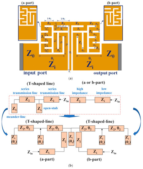
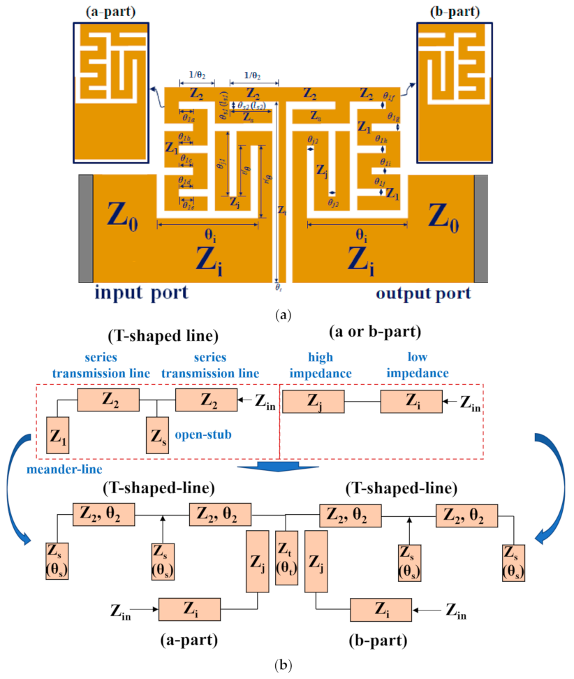
The proposed BPF features the SIR meander line, a folded structure, and a T-shaped line, as shown in Figure 1a, and the Figure 1b shows the equivalent circuit of the proposed BPF. From the Figure 1a, the SIR structure is expressed as open stubs with low and high impedances. The SIR presents a symmetric structure on both the left side (part a) and right side (part b). Z1 and Zj represent the low impedances of the meander line, and Zs represents the low impedance of the folded structures. In addition, Z2 and Zi represent the high impedances corresponding to the T-shaped lines, and Zt represents the high impedance of the T-shaped line. θ1 and θj represent the electrical lengths of the meander lines, and θs represents the electrical length of the folded structure. In addition, θ2 and θi represent the electrical lengths corresponding to the T-shaped lines, and θt represents the electrical length of the T-shaped line.
Figure 1.
(a) Structure and (b) equivalent circuit of proposed BPF.
The input admittance (Yin) of parts a and b is given by Equations (1) and (3) [15], which can be expressed using an equivalent circuit.
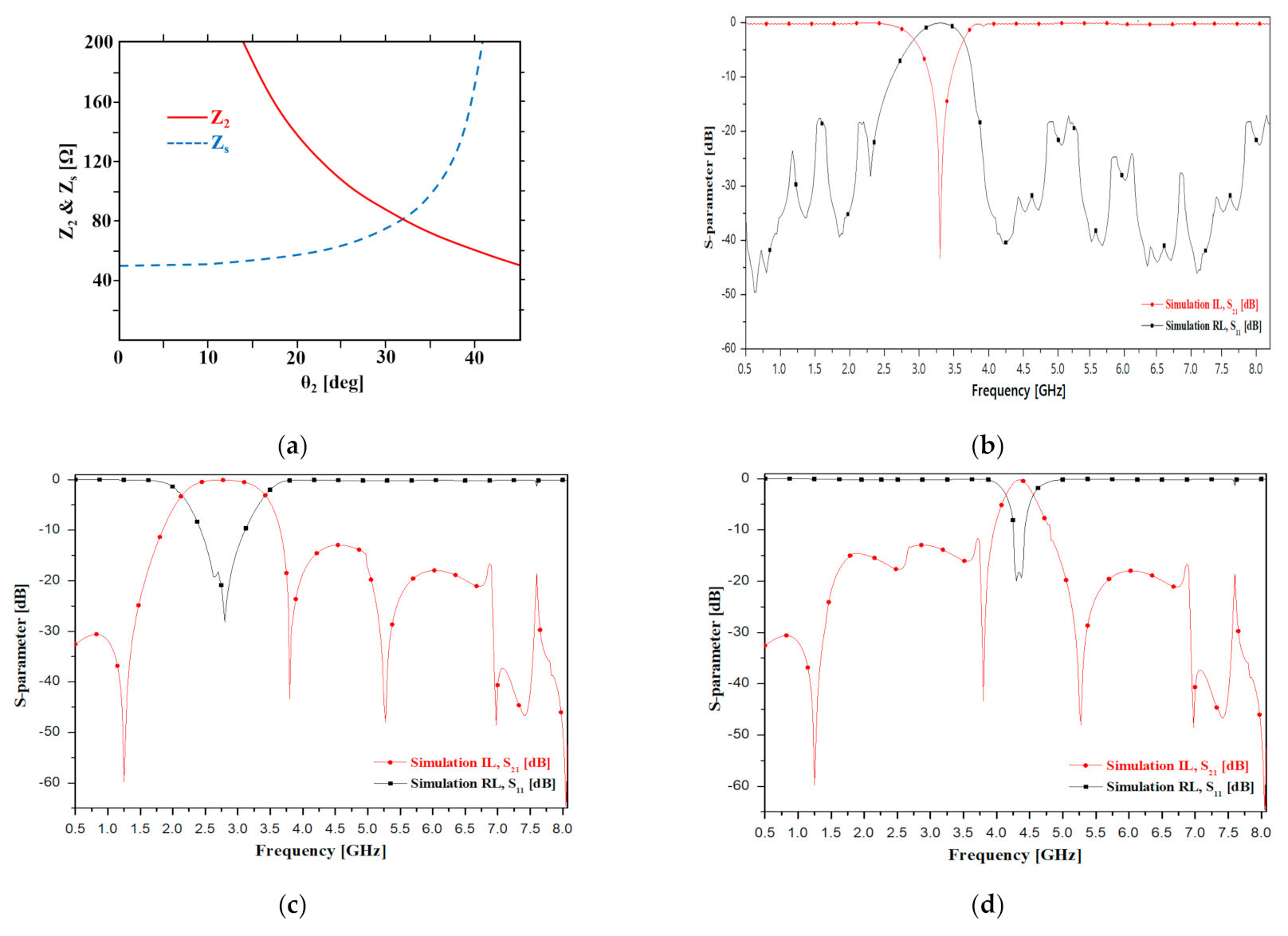
The T-shaped line (Z2 and Zs) operates as a wide-bandwidth BSF in the null-frequency range between the first and second frequency bands, as shown in Figure 1b. θ2 and θs lead to 30° and 45° in the null-frequency range [16]. Next, Z2 and Zs can be solved in Equation (4) using θ2:
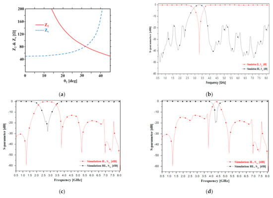
where θ2 must be above 0° and below 45° (2θ2 < θ2 = 90°). If θ2 is more than 45° (θ2 < 90°), Zs reaches infinity, as shown in Figure 2a. As the shunt stub is −jZs cot θs = ∞, the T-shaped structure acts like an open stub. Z2 and Zs are 86.6 and 75 Ω, respectively, and θ2 and θs are 30° and 45°, respectively. Figure 2b shows the simulation results for the BSF response between the first and second frequency bands using a T-shaped structure.
Figure 2.
Simulation results for parameter responses. (a) Variation of impedance (Z2 and Zs) according to θ2 and (b) BSF, (c) first frequency band, and (d) second frequency band responses.
The simulated insertion losses are 0.09 and 0.11 dB, respectively, and the simulated return losses are 24.8 and 23.4 dB at the first and second center frequencies of 3.85 and 5.95 GHz in the BSF, respectively.
The calculated impedance and electrical length of the equivalent circuit are listed in Table 1. Figure 2c,d shows the simulated passbands of the first and second frequency ranges for the proposed dual-band BPF, respectively. The simulated first and second center frequencies are 2.8 GHz (2.15–3.43 GHz) and 4.3 GHz (4.08–4.5 GHz), with bandwidths of 46% and 10%, respectively. The insertion losses of the first and second frequency bands are 0.024 and 0.023 dB, respectively, and the return losses of the first and second frequency bands are 18.6 and 19.6 dB, respectively. The BPF performs a dual-band operation when the T-shaped line is connected between parts a and b, as shown in Figure 1b.
Table 1.
Calculated electrical parameters.
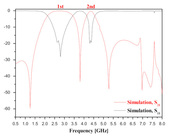
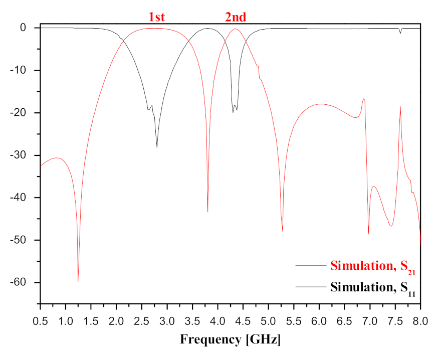
Parts a and b (Figure 1a) operate in the first and second frequency bands, respectively, and the T-shaped line serves as a BSF. More specifically, the filter for the design in the proposed BPF is integrated into a BPF and a BSF (a). Next, the BPF used an SIR resonator and the BSF feature a T-shaped-line structure. The BPF features a two-stage structure, in which the two stages are symmetrical. The SIR resonator is divided into a-part and b-part, and a coupling structure (g) is coupled between the a-part and the b-part. The coupling structure serves to connect the a-part and the b-part. At this point, a-part acts as a resonator for operating the first frequency band (1st), as shown in Figure 3, and b-part plays a role in the operation of the second frequency band (2nd).
Figure 3.
Frequency band response for 2 stage (a and b parts) SIR.
The a-part and b-part SIR resonators are composed of high impedance (Zj) and low impedance (Zi). At this point, when the impedance difference between Zj and Zi is provided in the SIR of the a-part and the b-part, the impedance ratio (Δ) must be adjusted to be greater than 1 (Δ > 1) [17]. The reason is that when Δ = Zj < Zi, the position of the harmonic of the SIR resonator changes, resulting in a dual-band resonant phenomenon. Therefore, a dual-band is formed due to the combination of two SIR resonators, and this filter constitutes a filter in dual mode [18,19].
The BSF operates through the structure of a T-shaped line. In general, the BPF features a π-type equivalent circuit. However, the BSF features a T-shaped equivalent circuit. BSFs are constructed with an electrical length within 90° of series (transmission line of Z2) and within 45° of parallel (open stub of Zs) within 90° of series for ease of design due to impedance and physical length or width. The transmission line (Z2) is symmetrical and functions as equivalent to 90° by calculating 30° to reduce the size, and the transmission line plays a role in transmitting the incident power to the output side. The stub cuts off the desired band in the process of transmitting power and, at this point, when the electrical length is 45° and 30°, the cut-off band can be adjusted.
In the T-shaped line, the meander-line corresponding to the impedance Z1, plays a micro-tuning role to reduce the insertion and return loss in the T-shaped BSF, and the size of the loss changes according to the change in the length of the transmission line.
The parallel open stub of the T-shaped line corresponding to the impedance of Zt serves as a clear boundary between the bandpass filter and the BSF so that the SIR BPF and the BSF of the T-shaped line can operate, respectively. At this point, it also serves as an intermediate connection for integrating the BPF and the BSF.
3. Design and Fabrication
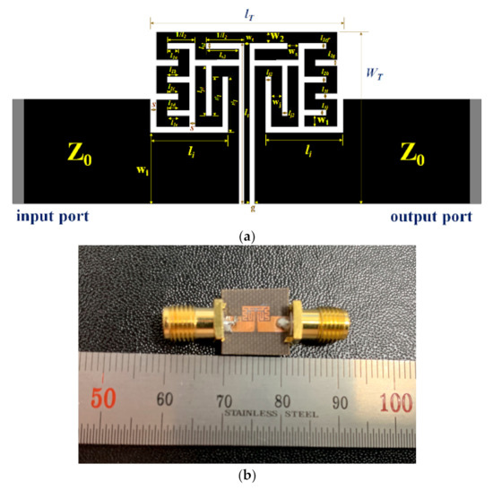
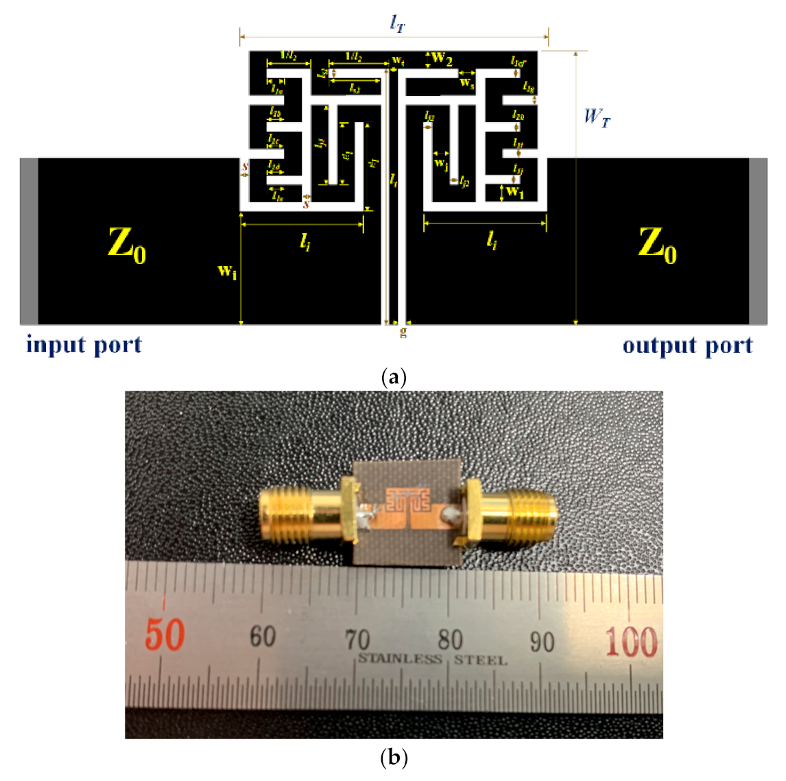
The proposed BPF was designed as shown in Figure 4a, and the Figure 4b shows the fabricated a proposed BPF. In the Figure 1a, the parameters l1 (a–e) and l1 (f–j) are 0.26 and 0.14 mm, respectively, and 1/l2 and lt are 0.66 and 3.82 mm, respectively. In addition, lj1 (=lj4), lj2, and lj3 are 0.93, 1.19, and 0.13 mm, respectively, while ls1, ls2, and li are 0.14, 0.78, and 1.84 mm, respectively.
Figure 4.
(a) Design layout and (b) fabricated BPF.
The parameters wi and w1 (w2 = wj = ws) are 1.69 and 0.26 mm, respectively, and wt, g, and s are 0.13, 0.12, and 0.14 mm, respectively, where s and g establish coupling structures and form the gap size. Parameters lT and WT are the total horizontal and vertical dimensions of 4.57 and 4.08 mm, respectively. Figure 4b shows the proposed BPF fabricated on a Teflon substrate with a low dielectric constant of 2.54 and a height of 0.54 mm. The size of the fabricated BPF is 24.0 × 16.4 mm.
4. Experimental Results
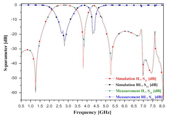
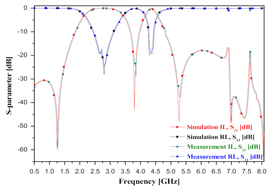
The simulation and measurement results for the proposed BPF are shown in Figure 5 The simulation results for the insertion and return losses of the first frequency passband (f01) are 0.024 and 18.3 dB, respectively, with a bandwidth of 46% at the center frequency of 2.8 GHz (2.15–3.43 GHz), and the insertion and return losses of second frequency passband (f02) are 0.023 and 18.2 dB, respectively, with a bandwidth of 10% at the center frequency of 4.35 GHz (4.08–4.5 GHz).
Figure 5.
Experimental results for proposed BPF.
In a fabricated BPF, the measurement results for the insertion and return losses of the first frequency passband (f01) are 0.042 and 17.3 dB, respectively, with a bandwidth of 46% at a center frequency of 2.8501 GHz (2.2–3.48 GHz), and the insertion and return losses of the second frequency passband (f02) are 0.026 and 17.2 dB, respectively, with a bandwidth of 10% at a center frequency of 4.3501 GHz (4.13–4.55 GHz).
Table 2 lists the characteristics, including bandwidth, insertion loss, and total size, of the proposed BPF and similar filters.
Table 2.
Characteristics of proposed BPF and similar filters.
In this paper, a designed BPF can be applied as a sensor suitable for use in chemicals, agriculture, medicine, and petroleum [20]. In particular, the frequency response characteristic of the filter is changed by a change in the capacitance value related to coupling. Therefore, biosensor applications are possible because the filter can detect specific substances on tissues [21].
5. Conclusions
A dual-band BPF using an SIR meander line, folded structure, and T-shaped line was proposed. The T-shaped line operates as a BSF, and the BSF divides the first and second frequency passbands on the BPF to achieve dual-band operation. The proposed BPF provides low insertion and return losses, a simple structure, and a compact size. In existing dual-band BPFs, a BSF is configured in addition to the BSF, or a BSF is integrated using the defected ground structure. However, these designs increase the size and deteriorate the filtering characteristics owing to the ground plane concentration loss. By contrast, the proposed design integrates a T-type structure at the center of the BPF. Therefore, size increase is avoided, and the ground-plane concentration loss is prevented. The measured insertion and return losses of the first frequency passband (f01) are 0.042 and 17.3 dB with a bandwidth of 46% at a center frequency of 2.8501 GHz (2.2–3.48 GHz), and the insertion and return losses of the second frequency passband (f02), are 0.026 and 17.2 dB, with a bandwidth of 10% at a center frequency of 4.3501 GHz (4.13–4.55 GHz). The proposed BPF is suitable for mobile communications systems owing to its planar structure.
Author Contributions
Design and simulation, T.-H.L.; analysis, K.-C.Y.; supervisors, K.-C.Y. and K.G.K. All authors have read and agreed to the published version of the manuscript.
Funding
This research was supported by the Bio & Medical Technology Development Program of the National Research Foundation (NRF) funded by the Ministry of Science & ICT (2017M3A9E2072929), GRRC program of Gyeonggi province. [GRRC-Gachon 2020 (B01), AI-based Medical Image Analysis and by the Gachon Gil Medical Center (FRD2019-11-02(3))].
Institutional Review Board Statement
Not applicable.
Data Availability Statement
The data presented in this study are available upon request from the corresponding author. The data are not publicly available because of privacy and ethical restrictions.
Acknowledgments
Tae-Hyeon Lee and Ki-Cheol Yoon contributed equally to this work. Tae-Hyeon Lee and Ki-Cheol Yoon are co-first authors. The device used for fabrication and measurement was installed at Jong-Chul Lee’s Laboratory and RFIC Research Center (Director and Nam-Young Kim) at Kwangwoon University in Seoul, Republic of Korea. Wet etching and metal coating were supported by the Gyeonggi University of Science and Technology in Siheung, Republic of Korea.
Conflicts of Interest
The authors declare no conflict of interest.
References
- Rao, Y.; Qian, H.J.; Yang, B.; Gómez-García, R.; Luo, X. Dual-band bandpass filter and filtering power divider with ultra-wide upper stopband using hybrid microstrip/DGS dual-resonance cells. IEEE Access 2020, 8, 23624–23637. [Google Scholar] [CrossRef] [Scilit]
- Wu, X.; Li, Y.; Liu, X. High-order dual-port quasi-absorptive microstrip coupled-Line bandpass filters. IEEE Trans. Microw. Theory Tech. 2020, 68, 1462–1475. [Google Scholar] [CrossRef] [Scilit]
- Gómez-García, R.; Yang, L.; Muñoz-Ferreras, J.; Psychogiou, D. Single/Multi-band coupled-multi-line filtering section and its application to RF diplexers, bandpass/bandstop filters, and filtering couplers. IEEE Trans. Microw. Theory Tech. 2019, 67, 3959–3972. [Google Scholar] [CrossRef] [Scilit]
- Gómez-García, R.; Yang, L.; Muñoz-Ferreras, J.; Psychogiou, D. Selectivity-enhancement technique for stepped-impedance-resonator dual-passband filters. IEEE Microw. Wirel. Compon. Lett. 2019, 29, 453–455. [Google Scholar] [CrossRef] [Scilit]
- Tang, J.; Liu, H.; Yang, Y. Balanced dual-band superconducting filter using stepped-impedance resonators with high band-to-band isolation and wide stopband. IEEE Trans. Circuits Syst.-II Express Briefs 2021, 68, 131–135. [Google Scholar] [CrossRef] [Scilit]
- Tang, J.; Liu, H.; Yang, Y. Compact wide-stopband dual-band balanced filter using an electromagnetically coupled SIR pair with controllable transmission zeros and bandwidths. IEEE Trans. Circuits Syst.-II Express Briefs 2020, 67, 2357–2361. [Google Scholar] [CrossRef] [Scilit]
- Wang, X.; Wang, J.; Choi, W.; Yang, L.; Wu, W. Dual-wideband filtering power divider based on coupled stepped-impedance resonators. IEEE Microw. Wirel. Compon. Lett. 2018, 28, 873–875. [Google Scholar] [CrossRef] [Scilit]
- Weng, M.H.; Lan, S.W.; Chang, S.J.; Yang, R.Y. Design of dual-band bandpass filter with simultaneous narrow- and wide-bandwidth and a wide stopband. IEEE Access 2019, 7, 147694–147703. [Google Scholar] [CrossRef] [Scilit]
- Zhu, C.; Xu, J.; Zhang, G.; Kang, W.; Wu, W. Split-type dual-band bandpass filters with symmetric/asymmetric response. IEEE Microw. Wirel. Compon. Lett. 2018, 28, 25–27. [Google Scholar] [CrossRef] [Scilit]
- Wei, F.; Yu, J.H.; Zhang, C.Y.; Zeng, C.; Shi, X.W. Compact balanced dual-band BPFs based on short. IEEE Trans. Circuits Syst. -II Express Briefs 2020, 67, 3043–3047. [Google Scholar] [CrossRef] [Scilit]
- Firmansyah, T.; Praptodinoyo, S.; Wiryadinata, R.; Suhendar, S.; Wardoyo, S.; Alimuddin, A.; Chairunissa, C.; Alaydrus, M.; Wibisono, G. Dual-wideband band pass filter using folded cross-stub stepped impedance resonator. Microw. Opt. Technol. Lett. 2017, 59, 2929–2934. [Google Scholar] [CrossRef] [Scilit]
- Wei, X.B.; Yue, G.T.; Liao, J.X.; Wang, P.; Xu, Z.Q.; Shi, Y. Compact dual-band band pass filter with ultra-wide upper-stop band. Electron. Lett. 2013, 49, 708–709. [Google Scholar] [CrossRef] [Scilit]
- Wu, Y.L.; Liao, C.; Xiong, X.Z. A dual-wideband bandpass filter based on E-shaped microstrip SIR with improved upper-stopband performance. Prog. Electromagn. Res. 2010, 108, 141–153. [Google Scholar] [CrossRef] [Scilit]
- Yoon, K.C.; Kim, S.C.; Lee, J.C. Compact low noise amplifier with high stable gain using distributed CRLH metamaterial. Microw. Opt. Technol. Lett. 2016, 58, 1715–1720. [Google Scholar] [CrossRef] [Scilit]
- Chu, Q.X.; Wu, X.H.; Tian, X.K. Novel UWB bandpass filter using stub-loaded multiple-mode resonator. IEEE Microw. Wirel. Compon. Lett. 2011, 21, 403–405. [Google Scholar] [CrossRef] [Scilit]
- Yoon, K.C.; Lee, J.C. Design of a 5.8 GHz narrow band-pass filter with second harmonic suppression using the open stubs. Microw. Opt. Technol. Lett. 2008, 50, 1763–1766. [Google Scholar] [CrossRef] [Scilit]
- Makimoto, M.; Yamashita, S. Microwave Resonators and Filters for Wireless Communication; Springer: Berlin/Heidelberg, Germany, 2014. [Google Scholar]
- Mokhtaari, M.; Bornemann, J.; Amari, S. Folded compact ultra-wideband stepped-impedance resonator filters. In Proceedings of the 2007 IEEE/MTT-S International Microwave Symposium, Honolulu, HI, USA, 3–8 June 2007; pp. 747–750. [Google Scholar]
- Crute, J.R.; Davis, L. A compact microstrip interdigital stepped-impedance bandpass filter with enhanced stopband. Microw. Opt. Technol. Lett. 2002, 34, 336–340. [Google Scholar] [CrossRef] [Scilit]
- Abdolrazzaghi, M.; Daneshmand, M.; Lyer, A.K. Strongly enhanced sensitivity in planar microwave sensors based on metamaterial coupling. IEEE Trans. Microw. Theory Tech. 2018, 66, 1843–1855. [Google Scholar] [CrossRef] [Scilit]
- Kazemi, N.; Abdolrazzaghi, M.; Musilek, P. Comparative analysis of machine learning techniques for temperature compensation in microwave sensors. IEEE Trans. Microw. Theory Tech. 2021, 69, 4223–4236. [Google Scholar] [CrossRef] [Scilit]

Publisher’s Note: MDPI stays neutral with regard to jurisdictional claims in published maps and institutional affiliations. |
© 2022 by the authors. Licensee MDPI, Basel, Switzerland. This article is an open access article distributed under the terms and conditions of the Creative Commons Attribution (CC BY) license (https://creativecommons.org/licenses/by/4.0/).