


Highlights
What are the main findings?
- At 0.025 N/m, weak capillarity caused necking, pinch-off, and bubble detachment.
- Raising σ from 0.025 to 0.075 N/m cut central-finger penetration by 33.3% at 1 s.
- At 0.04 m/s, shear-thickening resistance drove tip splitting and trapped STF pockets.
- A +1° gap-depth gradient created a 7 mm disparity between wall-adjacent fingers.
What are the implications of the main findings?
- Capillary control stabilizes topology but may reduce displacement-front uniformity.
- Injection velocity is a key control variable for preventing rheological breakthrough.
- Gap-depth gradients offer a passive strategy to steer the preferential flow path.
- These mechanisms inform reliable fracture sealing and efficient semi-solid flow batteries.
Abstract
Viscous fingering is a canonical nonlinear interfacial instability that arises when a less viscous fluid displaces a more viscous one under an adverse viscosity contrast. Despite extensive investigations into the effects of fluid properties, operating conditions, and rheology, systems involving a shear-thickening displaced phase remain largely unexplored. Here, three-dimensional numerical simulations of immiscible air–fluid displacement in a Hele–Shaw cell are performed to elucidate how interfacial tension, air-inlet velocity, and gap-depth gradient regulate instability evolution. Increasing interfacial tension strengthens the Laplace-pressure barrier, suppresses shear-induced necking and pinch-off, and preserves finger topology; however, it intensifies flow diversion and delays the advancement of the central finger. Increasing the inlet velocity markedly amplifies the local interfacial shear rate and triggers pronounced shear thickening. The resulting viscous-resistance barrier redistributes momentum toward paths of least hydraulic resistance, directly promoting tip splitting and severe topological breakup. Even a small gap-depth gradient reorganizes the local hydraulic resistance and pressure field. Positive and negative gradients induce resistance-reduction and throttling effects, respectively, generating pronounced pressure shielding that governs asymmetric momentum transfer and preferential flow-path selection. These findings identify the capillary, rheological, and geometric mechanisms controlling viscous fingering during the air-driven displacement of shear-thickening fluids. Because such instabilities compromise the integrity of geological-fracture seals and the operating efficiency of semi-solid flow batteries, this study provides a mechanistic basis for stabilizing immiscible displacement and optimizing industrial fluid-transport systems.
1. Introduction
Viscous fingering is a nonlinear interfacial instability that arises when a less viscous fluid invades and displaces a more viscous fluid in a two-phase system. Driven by the viscosity contrast and the resulting imbalance in momentum transfer across the interface, an initially planar interface progressively deforms into complex, irregular finger-like protrusions [1,2,3]. This phenomenon arises in—and often critically affects—a broad range of engineering, including geological fracture remediation and sealing, semi-solid flow batteries, and vibration-damping systems [4,5,6,7,8]. In engineering applications involving the sealing of geological fractures with shear-thickening fluids (STFs), a moderate injection pressure can promote particle jamming within the fluid and thereby enhance sealing performance. However, as the driving pressure continues to increase, intense localized pressure can overcome the viscous-resistance barrier established by the shear-thickening fluid (STF), triggering severe viscous fingering and multidirectional interfacial breakup that ultimately compromises the stability of the sealing structure [9]. A similar challenge arises in semi-solid flow batteries, whose electrolytes can exhibit shear-thickening non-Newtonian behavior. During electrolyte displacement into the electrochemical reaction chamber, viscous fingering increases the energy required for fluid transport and consequently reduces the overall power-generation efficiency [10,11,12,13,14]. A mechanistic understanding of the initiation and evolution of viscous fingering during the air-driven displacement of shear-thickening fluids is therefore of both fundamental and practical importance.
Viscous fingering has been extensively investigated through experiments, theoretical and analytical models, and numerical simulations. Zhao et al. [15] experimentally investigated viscous fingering in a one-end-lifted Hele–Shaw cell, in which the continuously varying gap thickness imposes spatially nonuniform boundary conditions. They demonstrated that this geometric configuration can enhance and regulate interfacial instability, generating densely branched hierarchical patterns whose characteristic finger width follows an inverse capillary-number scaling with exponents ranging from 0.53 to 1.22. Using a cross-validated numerical framework based on two independent hydrodynamic solvers, Bakharev et al. [16] quantified the effects of macroscopic control parameters on finger growth and established classification criteria for the resulting fluid-channeling regimes. Combining experiments with a depth-averaged numerical model, Fontana et al. [17] investigated air-finger propagation in a Hele–Shaw channel with an elastic upper boundary and an initially collapsed cross-section. They identified a capillary-number threshold separating viscous-dominated and elasticity-dominated reopening regimes and showed that increasing the propagation speed and degree of collapse produces progressively more complex and unsteady interfacial patterns, including pointed, indented, and feathered fingers. Ait Abderrahmane et al. [18] employed finite-element simulations with an inertia-corrected depth-averaged formulation to examine miscible displacement in a circular Hele–Shaw cell. Their results indicated that inertia stabilizes the displacement front and improves sweep efficiency at large mobility ratios while slightly suppressing tip splitting and fluid mixing under appropriate conditions. In complementary work, Anjos et al. [19] combined stability analysis and nonlinear simulations to develop time-dependent injection and lifting strategies for controlling wetting-film-mediated fingering, showing that wetting increases the required control intensity. Collectively, experimental, theoretical, and numerical studies of classical Newtonian displacement systems have substantially advanced our understanding of how fluid properties, operating conditions, rheological parameters, and external physical fields regulate the evolution of interfacial instabilities [20,21,22,23].
Compared with their Newtonian counterparts, viscous-fingering instabilities involving non-Newtonian fluids received relatively little attention in early studies. Recognition that complex rheology can fundamentally reorganize the spatiotemporal evolution of unstable interfaces has, however, stimulated increasing interest in systems containing a non-Newtonian displaced phase. Lee et al. [24] experimentally isolated the effects of normal-stress differences by employing dilute low-molecular-weight poly(ethylene oxide) solutions with nearly constant shear viscosity. They identified a nonmonotonic, stage-dependent elastic response: increasing the polymer molecular weight promoted tip splitting and produced narrower fingers during the early stage but suppressed tip splitting during the intermediate stage. Ahmadikhamsi et al. [25] systematically investigated the influence of surfactants on the displacement of non-Newtonian polymer solutions in a radial Hele–Shaw cell. They found that the surfactant-induced reductions in local interfacial tension and fluid viscosity generate wider viscous fingers at high capillary numbers than those observed in surfactant-free polymer solutions. For the displacement of shear-thinning fluids in porous media, Wang et al. [26] employed the lattice Boltzmann method to demonstrate that stronger shear-thinning behavior intensifies velocity-induced viscosity heterogeneity, which macroscopically attenuates the interfacial instability associated with viscous fingering. Singh and Mondal [27] developed a rheology-dependent, time-varying injection strategy for suppressing radial viscous fingering in power-law fluids. Using three-dimensional volume-of-fluid simulations. Wu et al. [28] showed that wall and contact-line effects promote tip splitting, whereas interfacial tension stabilizes the interface. Parmar and Bandyopadhyay [29] linked the transition from viscous fingering to dendritic growth and viscoelastic fracture to permeability heterogeneity and bulk elasticity. Dufresne et al. [30] demonstrated that yield stress governs finger-width selection, while wall slip modifies and generally weakens the instability. For the displacement of shear-thinning fluids in porous media, Adriazola et al. [31] developed a history-dependent numerical model and demonstrated that shear thinning produces fingering patterns with a smaller fractal dimension than Newtonian fluids. Ref. [32] developed an efficient gap-averaged model that accurately captures the displacement and viscous fingering of power-law fluids in Hele–Shaw cells.
Despite these advances, the existing literature remains heavily biased toward systems in which the displaced phase is shear-thinning. By contrast, viscous fingering during the displacement of shear-thickening fluids remains conspicuously underexplored. Consequently, a systematic understanding of how geometric confinement, capillarity, and flow-rate effects regulate air-driven interfacial instability in shear-thickening fluids is still lacking. In particular, the roles of gap-depth gradients, surface tension, and initial inlet velocity conditions—and the manner in which these factors collectively determine finger morphology and propagation—have not been adequately resolved. This knowledge gap is especially consequential because shear-thickening fluids are increasingly employed in oil and gas engineering, impact- and vibration-damping devices, and the sealing of geological fractures, where uncontrolled fingering can directly compromise transport efficiency, structural integrity, and operational reliability.
Although the present Hele–Shaw cell is geometrically idealized, it provides a representative local model of immiscible displacement in a narrow, confined passage. For geological-fracture sealing, the cell gap may be interpreted as a local fracture aperture, while the imposed gap-depth gradient represents a simplified aperture variation. For semi-solid flow systems, the geometry represents an idealized narrow transport channel or reaction-chamber segment. Therefore, the present model is intended to identify the local mechanisms associated with capillarity, shear-thickening rheology, and geometric confinement rather than reproduce a complete fracture network or industrial device.
In summary, this study employs three-dimensional numerical simulations to systematically investigate the evolution of viscous fingering during the air-driven displacement of a shear-thickening fluid in a Hele–Shaw cell (HSC). Building on a detailed characterization of the rheological behavior of the displaced phase, particular emphasis is placed on elucidating the combined effects of the gap-depth gradient, surface tension, and initial inlet velocity on the mechanisms governing interfacial instability.
2. Numerical Method
Three-dimensional volume-of-fluid simulations were performed in ANSYS Fluent 2021 R1 to investigate the air-driven displacement of a shear-thickening fluid in a Hele–Shaw cell. The gas–liquid interface was captured on a fixed Eulerian mesh, and the shear-thickening fluid (STF) rheology was described using a generalized-Newtonian power-law model. The effects of interfacial tension, inlet velocity, and gap-depth gradient on viscous-fingering evolution were systematically examined. Both phases were assumed to be incompressible, immiscible, and isothermal, with no phase change or interphase mass transfer. Air was treated as a constant-property Newtonian fluid, whereas the shear-thickening fluid (STF) was modeled as a homogeneous generalized-Newtonian continuum with a shear-rate-dependent apparent viscosity. A constant interfacial tension was assumed. Gravity was neglected, and the suspended particles were not resolved as a separate phase; therefore, particle sedimentation, migration, and local concentration variations were not considered. The cell walls were assumed to be rigid and geometrically smooth.
For flow dynamics in Hele–Shaw systems, the governing equations are generally formulated on the basis of Darcy’s law averaged across the gap depth. Accordingly, the depth-averaged velocity of each fluid phase is expressed as follows:
where and are the phase j depth-averaged pressure and velocity vectors, respectively.
Equation (1) represents the classical depth-averaged Hele–Shaw relation. It is obtained under the thin-gap approximation, for which the gap depth is much smaller than the streamwise and transverse dimensions of the cell. The flow is assumed to be predominantly parallel to the plates, the pressure variation across the gap is neglected, and the velocity satisfies the no-slip condition at the walls. Under laminar conditions with weak inertial effects, integration of the momentum equation across the gap yields the depth-averaged pressure–velocity relation given in Equation (1). In the present study, this equation is used to illustrate the dependence of hydraulic resistance on the local gap depth and apparent viscosity, whereas the numerical simulations are performed by solving the three-dimensional conservation equations coupled with the volume-of-fluid method.
Given the relatively low bulk flow velocities in the system, the flow can be reasonably approximated as incompressible. The continuity equation therefore reduces to:
where denotes the velocity vector, and the corresponding equation of motion is given by:
In the formula, p represents pressure, represents density, represents dynamic viscosity, I represents identity tensor, represents time, represents surface tension.
The numerical simulations were performed using ANSYS Fluent. To accurately capture the two-phase interface and resolve the spatial morphology of viscous fingering, the volume-of-fluid model formulated on a fixed Eulerian mesh was employed to dynamically track the moving interface. This approach assumes that the fluid phases are immiscible and identifies the local phase distribution through the volume fraction calculated in each computational cell. In the volume-of-fluid formulation, a single set of coupled pressure and momentum equations is solved throughout the entire computational domain, yielding a velocity field shared by all fluid phases. The dynamic evolution of the system is governed by the mass-weighted mixture continuity and momentum conservation equations. In the absence of interphase mass transfer, the governing equations can be expressed as follows:
where the subscript denotes either the gas phase () or the liquid phase (l), with . Here, is the velocity field of phasa , is its volume fraction, is its density, (p) is the pressure, is its dynamic viscosity, is the gravitational acceleration vector, and is the surface-tension force. Within this volume-of-fluid framework, the classical mathematical boundary conditions at the two-phase interface are implicitly resolved. The kinematic condition of velocity continuity is satisfied by solving a single, shared velocity field for both phases, assuming no slip across the interface. The dynamic boundary condition, which dictates the stress balance across the interface (i.e., the Laplace pressure jump), is mathematically implemented via the Continuum Surface Force (CSF) model. The CSF model transforms the singular interfacial force into a localized volumetric continuous body force (), thereby enforcing the normal stress balance directly within the momentum equations.
Under the incompressibility assumption, Equation (2) expresses conservation of mass. Equation (3) represents momentum conservation for an incompressible fluid, including viscous, pressure, gravitational, and surface-tension contributions. Equations (4) and (5) are applied within the volume-of-fluid framework under the assumptions that the phases are immiscible and that no phase change or interphase mass transfer occurs. Equation (6) treats the shear-thickening fluid (STF) as a generalized-Newtonian power-law fluid and is applicable within the shear-rate range over which the rheological parameters were determined. This constitutive model captures the dependence of apparent viscosity on shear rate but does not account for viscoelasticity, normal-stress effects, thixotropy, particle migration, or particle-scale jamming.
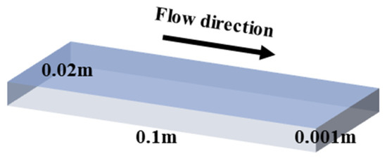
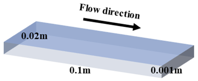
As shown in Figure 1, a three-dimensional rectangular Hele–Shaw cell with a length of 10 cm, a width of 2 cm, and a gap thickness of 1 mm was employed. These dimensions provide strong geometric confinement and sufficient space for the development of viscous fingers while maintaining a reasonable computational cost. The millimeter-scale gap is also consistent with the dimensions used in previous Hele–Shaw studies, such as Anjos and Miranda [33]. In practical applications, the gap may represent a local fracture aperture or a narrow transport-channel segment. Thus, this idealized geometry was selected to investigate the local effects of capillarity, shear-thickening rheology, and geometric confinement rather than to reproduce a full-scale engineering system.
Figure 1.
Three-dimensional geometric model of the Hele–Shaw cell [34].
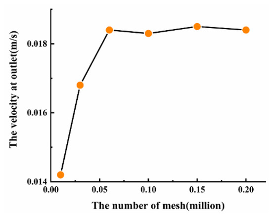
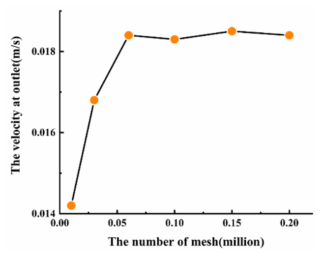
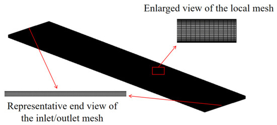
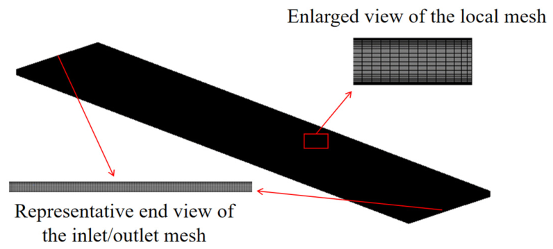
The grid-independence results presented in Figure 2 show that, once the number of mesh cells exceeded 67,000, the outlet velocity became essentially insensitive to further grid refinement, indicating that grid-independent solutions had been achieved. Accordingly, a mesh containing 103,000 cells was adopted in the previous study. To further improve the spatial resolution of the three-dimensional gas–liquid interface and the local pressure and velocity gradients, the present computational domain was discretized using approximately 1.4 million high-quality structured cells, with additional local refinement applied in the near-wall boundary-layer regions (Figure 3). This refined mesh was adopted to improve the spatial resolution of the gas–liquid interface and the local pressure and velocity gradients. Boundary-layer elements were generated adjacent to the wall boundaries using the smooth-transition inflation method. A maximum of 10 inflation layers was employed, with a growth rate of 1.2 and a transition ratio of 0.272. The body and wall-edge element sizes were 2.0 × 10⁻⁴ and 1.0 × 10⁻⁴ m, respectively. The corresponding nominal first-layer height and total inflation thickness were approximately 5.27 × 10⁻⁶ and 1.37 × 10⁻⁴, respectively. The inflation layers were introduced to resolve the steep near-wall velocity and shear-rate gradients and thereby improve the calculation of the shear-rate-dependent apparent viscosity. The moderate growth rate of 1.2 was selected to provide a smooth transition from the near-wall elements to the interior mesh.
Figure 2.
Verification of mesh independence.
Figure 3.
Computational mesh of the domain.
For the boundary conditions, a constant air injection velocity of was imposed at the inlet, while a pressure-outlet boundary condition with a gauge pressure of was prescribed at the outlet to represent discharge directly into the atmosphere. Because this study focuses on the influence of shear-thickening behavior on the evolution of viscous fingering, the displaced phase was modeled as a non-Newtonian fluid, and its rheological behavior was described using the power-law constitutive model implemented in the numerical solver.
where denotes the shear rate and n is the dimensionless flow behavior index that characterizes the dependence of the apparent viscosity on the local shear rate. In the present study, n = [1.4] was used. Since n > 1, the modeled non-Newtonian fluid exhibits shear-thickening behavior. A larger n indicates a stronger dependence of the apparent viscosity on the local shear rate and may consequently alter the pressure drop, interface propagation, breakup behavior, and critical-velocity interval. However, the present study focuses only on the case of n = [1.4], and a systematic parametric analysis of n is beyond the scope of the current work. Therefore, the conclusions should be understood as being applicable to the specified rheological parameters.
To qualitatively assess the capability of the present numerical model to capture shear-thickening viscous fingering, the predicted interfacial evolution was compared with the morphological characteristics experimentally reported by Kagei et al. [35] for the air-driven displacement of a shear-thickening silica suspension in a linear Hele–Shaw cell. Their experimental observations indicated the formation of elongated and nonuniform air fingers, together with localized interfacial narrowing and increasingly pronounced deformation under stronger driving conditions. Similar morphological characteristics were obtained in the present simulations, in which increasing the inlet velocity enhanced interfacial deformation and promoted finger elongation, necking, and topological breakup. Despite differences in cell dimensions, material properties, rheological parameters, and operating conditions, the overall morphological trends predicted by the present model are qualitatively consistent with those reported experimentally. This agreement provides supporting evidence that the present volume-of-fluid framework can capture the principal macroscopic features of air-driven viscous fingering in a shear-thickening fluid.
The selected parameter values were chosen to represent distinct capillary, rheological, and geometric conditions. The intermediate interfacial tension of 0.055 N m−1 was adopted as a representative value for an air–shear-thickening-fluid interface, while 0.025 and 0.075 N m−1 represent relatively weak and strong capillary effects, respectively. The baseline inlet velocity of 0.02 m s−1 follows the air–glycerin Hele–Shaw simulation of Singh et al. [36], and 0.01 and 0.04 m s−1 were selected as one-half and twice this reference value to represent low- and high-driving conditions. The gap angles of α = 0.5°, α = 1.0°, α = 0°, α = −0.5° and α = −1.0° were selected based on the small-taper framework of Al-Housseiny and Stone [37] to compare parallel, slightly diverging, and slightly converging geometries. These values were intended to distinguish the governing physical mechanisms rather than construct a complete parametric map.
3. Influence of Interfacial Tension on the Air-Driven Displacement of a Shear-Thickening Fluid
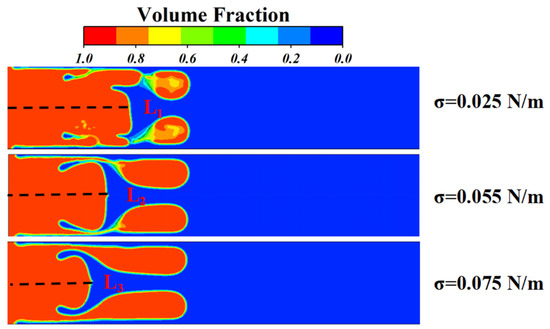
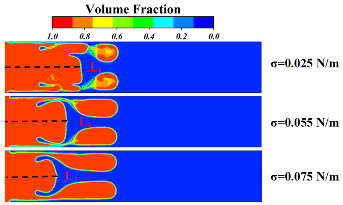
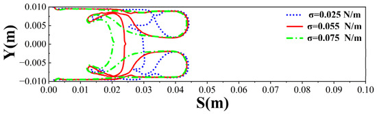
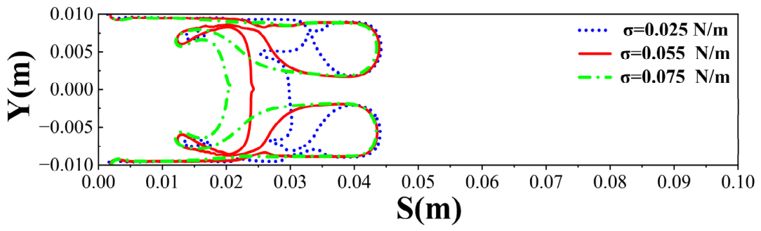
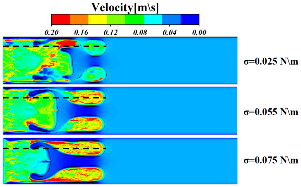
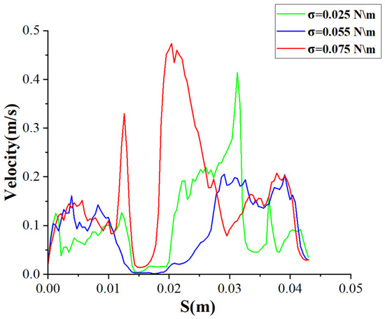
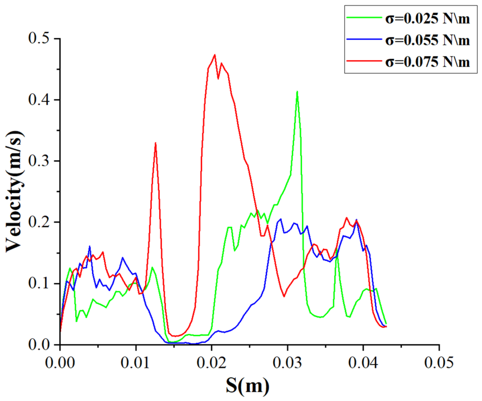
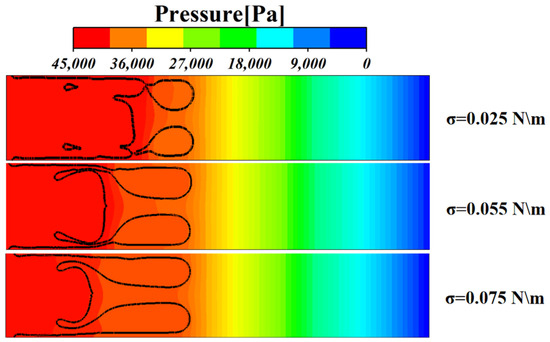
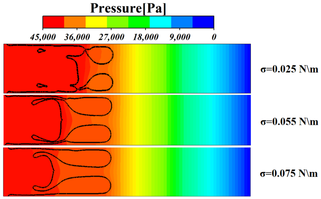
In practical applications such as geological engineering and semi-solid flow batteries, the large contrast in physical properties between the gas and liquid phases gives rise to complex interfacial morphologies during the air-driven displacement of a shear-thickening fluid (STF). These evolving interfaces may produce preferential-flow short-circuiting or localized blockage, thereby reducing displacement efficiency and overall process performance. As a key dynamic parameter governing interfacial instability, interfacial tension can substantially alter the viscous-fingering patterns generated during two-phase displacement. Accordingly, this study systematically investigates the evolution of viscous fingering under different interfacial-tension conditions. The interfacial tension was incorporated using the continuum surface force (CSF) model and was set to and N m−1. Figure 4 presents the viscous-fingering morphologies at (t = 1 s) for the three interfacial tensions. In all cases, the displacement front developed three distinct air pathways: two slender, vertically symmetric fingers adjacent to the upper and lower walls and a shorter, wider central finger. The corresponding interface profiles were extracted to obtain the finger-position distributions shown in Figure 5. Under all three conditions, the leading wall-adjacent fingers reached the streamwise position (S = 0.044 m), indicating that interfacial tension had little effect on the maximum front position at this instant. It nevertheless strongly affected the connectivity and local stability of the fingers. At the lowest interfacial tension, N m−1), the roots of the two slender fingers could not withstand the intense local shear. Pronounced necking developed and ultimately caused interfacial pinch-off, after which the detached air bubbles were transported downstream with the displaced fluid. The velocity contours in Figure 6 show that the main air region retained high but strongly heterogeneous velocities, while the slender pathways near the advancing front had already been severed. At this low interfacial tension, the weak capillary restoring force was insufficient to counteract the intense local deformation induced by the nonuniform velocity field. To further resolve the internal flow dynamics, the velocity profile from the finger root to the advancing front was extracted along the black dashed path in Figure 4, as shown in Figure 7. As the air passed through the necking region between S = 0.030 m and S = 0.040 m, the local velocity abruptly decreased from 0.42 m s−1 to 0.05 m s−1, corresponding to a reduction of approximately 88%, before recovering to 0.15 m s−1. This pronounced velocity fluctuation indicates substantial momentum dissipation and redistribution within the necking region. The resulting steep spatial velocity gradient intensifies local axial extension and promotes thinning of the finger root, ultimately leading to interfacial rupture and bubble detachment. The pressure field provides additional evidence for this mechanism. As shown in Figure 8, when N m−1), the interface has limited resistance to deformation, and the steep local pressure gradient overwhelms the weak capillary restoring stress. This imbalance destabilizes the roots of the slender fingers, amplifies necking, and ultimately disconnects the air pathways. The combined velocity and pressure distributions therefore indicate that pinch-off at low interfacial tension results from strong local momentum and pressure gradients acting on an interface with insufficient capillary resistance.
Figure 4.
Gas–liquid interfacial morphologies at t = 1.0 s for σ = 0.025, 0.055, and 0.075 N m−1. The inlet velocity was 0.02 m s−1. The dashed lines indicate the streamwise positions of the central-finger fronts, corresponding to penetration lengths L1, L2, and L3, respectively. The colors identify the gas and liquid phases, and no normalization was applied.
Figure 5.
Finger-front positions at t = 1.0 s for σ = 0.025, 0.055, and 0.075 N m−1. The inlet velocity was 0.02 m s−1, and no normalization was applied.
Figure 6.
Velocity magnitude contours at t = 1.0 s for σ = 0.025, 0.055, and 0.075 N m−1. The colors represent the dimensional velocity magnitude in m s−1, from low values in blue to high values in red. The inlet velocity was 0.02 m s−1, and no normalization was applied. The black dashed lines indicate the sampling paths along the upper wall-adjacent fingers used to extract the velocity-magnitude profiles presented in Figure 7.
Figure 7.
Velocity magnitude profiles along the upper wall-adjacent finger at t = 1.0 s for σ = 0.025, 0.055, and 0.075 N m−1. The data are dimensional and were extracted along the path marked in Figure 4.
Figure 8.
Gauge-pressure contours at t = 1.0 s for σ = 0.025, 0.055. The colors represent the dimensional gauge pressure in Pa relative to the outlet pressure of 0 Pa. The inlet velocity was 0.02 m s−1, and no normalization was applied. The black lines represent the gas–liquid interfaces.
Compared with the low-interfacial-tension case of N m−1), increasing the interfacial tension to the intermediate value of N m−1) substantially stabilized the displacement interface. The two slender wall-adjacent fingers retained greater structural continuity and formed clearly defined, uninterrupted flow pathways, although necking remained evident at their roots. When the interfacial tension was further increased to N m−1), the interface exhibited even greater stability. The curvature of the two slender fingers varied more smoothly, while their roots became wider and more resistant to disconnection. Comparison of the wall-adjacent fingers under the three conditions demonstrates that a low interfacial tension promotes interfacial instability and severe necking. Mechanistically, interfacial tension provides a curvature-dependent restoring stress that opposes local deformation. At low interfacial tension, viscous shear dominates the interfacial stress balance, allowing the interface to be strongly elongated, locally detached, and ultimately ruptured. As the interfacial tension increases, capillary forces become increasingly important and resist the development of high-curvature perturbations, thereby preserving the structural and topological integrity of the fingers. This interpretation is consistent with the capillary-stabilization mechanism described by Oliveira [38]. The velocity profiles in Figure 7 provide further hydrodynamic evidence for this mechanism. At N m−1) and N m−1), the slender fingers maintained high local velocities over the interval S = 0.032–0.040, substantially exceeding those observed at ( N m−1). This sustained momentum transport indicates that the wall-adjacent pathways remained hydraulically connected, allowing momentum to be transmitted continuously toward the advancing front. Together with the enhanced capillary restoring force, this uninterrupted momentum transfer supported the smooth and coherent propagation of the viscous fingers. To quantify the competition between viscous and capillary effects, the representative liquid velocity was extracted from the region between the two wall-adjacent fingers. The reference shear rate was estimated as
and the corresponding apparent viscosity, , was calculated using Equation (6). The local capillary number was then defined as
where h and σ denote the cell gap and interfacial tension, respectively. For interfacial tensions of 0.025, 0.055, and 0.075 N m−1, the local velocities were 0.024, 0.018, and 0.0024 m s−1, respectively, yielding local capillary numbers of 3.37, 1.02, and 4.47 × 10⁻². The substantial decrease in the capillary number indicates a transition from viscous-dominated deformation to capillary-dominated stabilization. At the lowest interfacial tension, viscous stresses promoted interfacial stretching, necking, and pinch-off. By contrast, at the highest interfacial tension, capillary restoration strongly suppressed local deformation. The reduced capillary number in the central region also supports the observed retardation of the central finger and the preferential diversion of air toward the hydraulically connected wall-adjacent pathways. The pressure distributions in Figure 8 provide a consistent explanation. With increasing interfacial tension, the isobars near the advancing front became progressively more widely spaced, indicating a lower local pressure gradient and a smoother pressure transition. For a given interfacial curvature, a higher interfacial tension produces a larger Laplace pressure jump and therefore a stronger resistance to localized deformation. This enhanced capillary resistance weakens the penetration of localized high-pressure disturbances and distributes the pressure load more uniformly along the front. The resulting pressure field promotes coherent interface advancement, suppresses necking and pinch-off, and improves the continuity of the viscous-fingering pathways.
In addition to altering the spatial continuity of the two wall-adjacent fingers, interfacial tension systematically modified the morphology of the central air finger. As the interfacial tension increased, the penetration length (L) of the central pathway progressively decreased, as indicated by the dashed lines in Figure 4. Specifically, when increased from ( N m−1) to ( N m−1) and ( N m−1), the central-front position decreased from L1 = 0.030 m to L2 = 0.024 m and L3 = 0.020 m, respectively (Figure 5). These values represent reductions of 20.0% and 33.3% relative to the ( N m−1) case. This retardation can be attributed to flow partitioning by the two slender wall-adjacent fingers. Once these fingers form hydraulically connected pathways, the injected air preferentially propagates through them because they offer lower flow resistance. The velocity contours in Figure 6 show markedly lower velocities within the central pathway, whereas the high-velocity regions are concentrated in the two wall-adjacent fingers. This distribution indicates that most of the injected air flux and momentum is redirected toward the side pathways, substantially reducing the driving momentum available to advance the central interface. Consequently, an extensive low-velocity or near-stagnant region develops in the central pathway, providing direct hydrodynamic evidence for the delayed propagation of the central finger. Interfacial tension therefore has a dual effect: it improves the topological integrity of individual fingers while intensifying competition among the available pathways and reducing the spatial uniformity of the displacement front.
4. Influence of Initial Air-Injection Velocity on the Displacement of a Shear-Thickening Fluid
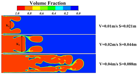
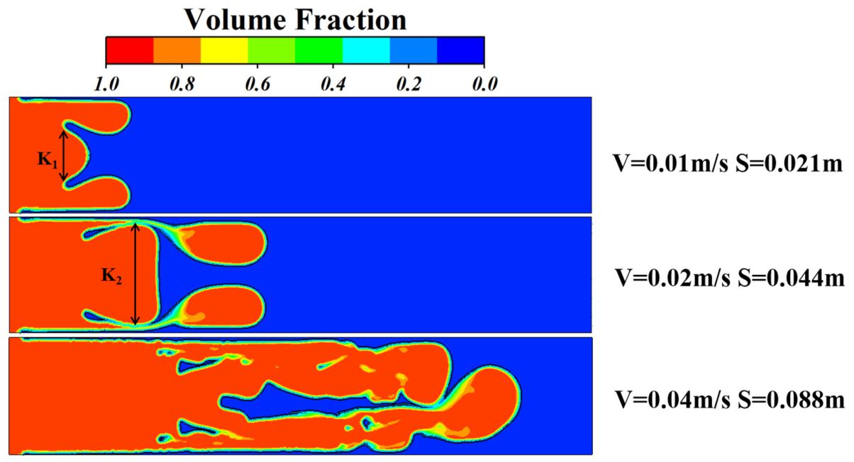
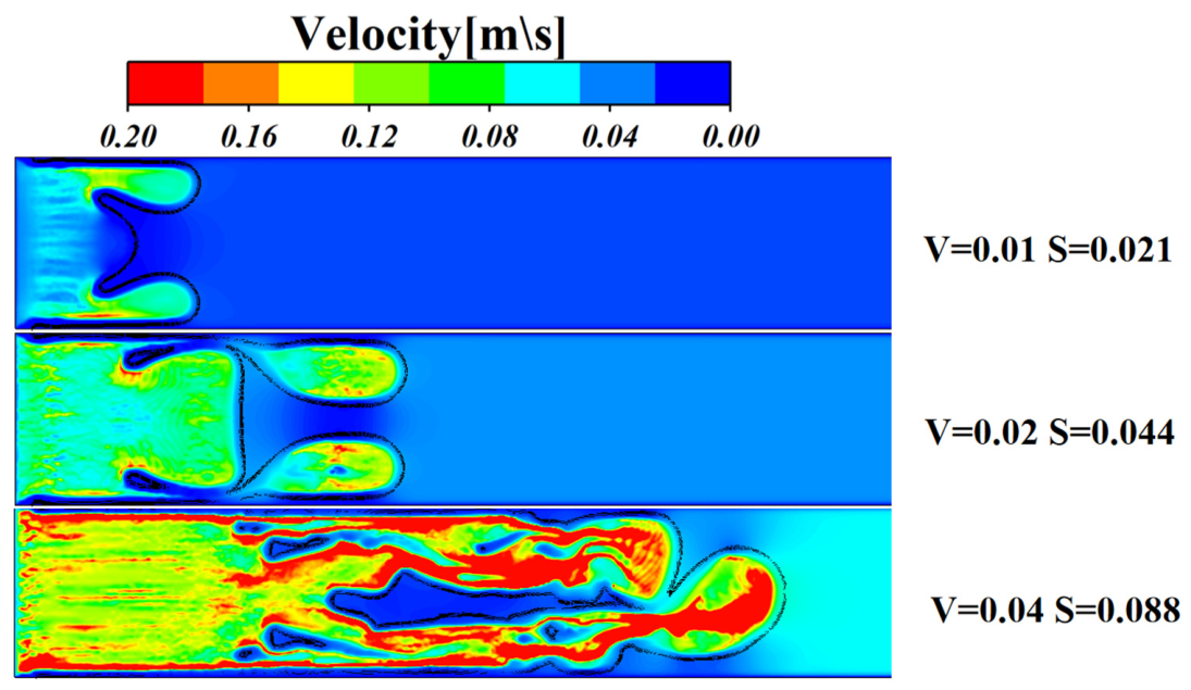
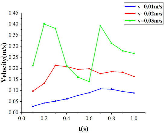
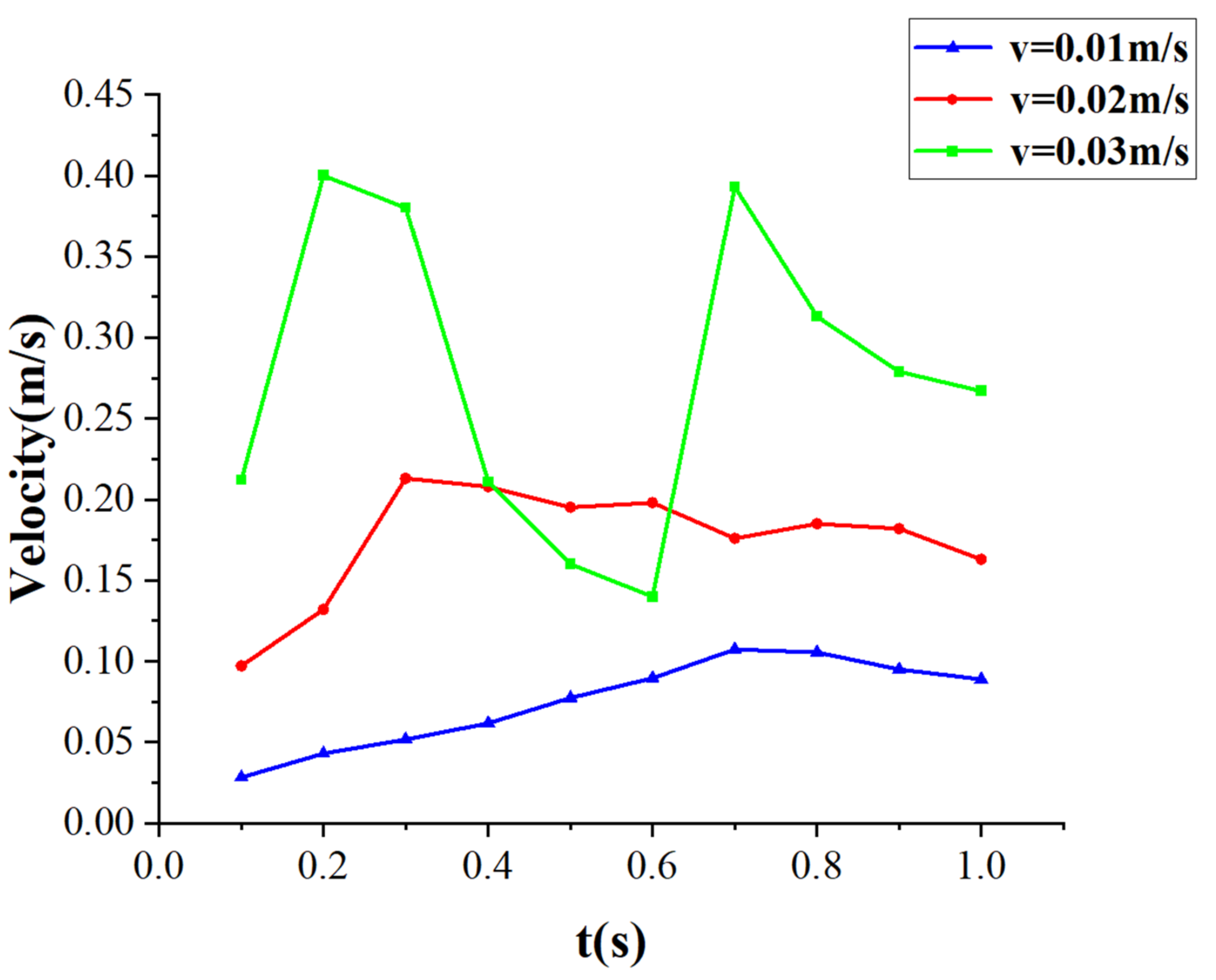
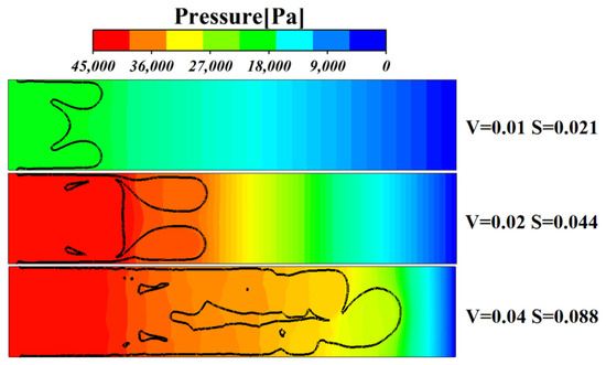
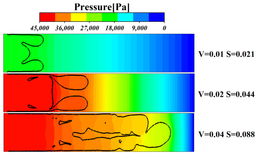
To investigate the influence of the initial air-injection velocity on the displacement of a shear-thickening non-Newtonian fluid, initial inlet velocities of v = 0.01 m s−1, 0.02 m s−1, 0.04 m s−1 were imposed. The finger penetration depth and front morphology obtained under these conditions at t = 1 s were compared, as shown in Figure 9. At v = 0.01 m s−1, the air penetration depth was S = 0.021 m s−1, and the gas–liquid interface evolved relatively smoothly. The slender fingers adjacent to the upper and lower walls remained short, with their tips extending only 0.0075 m beyond the central finger front. When v was increased to 0.02 m s−1, the penetration depth increased to S = 0.044 m, and the slender fingers elongated substantially. Meanwhile, the vertical span K of the central finger increased to 1.7 times that obtained at v = 0.01 m s−1, i.e., (K1/K2 = 1.7). As the injection velocity was further increased to v = 0.04 m s−1, the gas penetration depth reached S = 0.088 m. Under this condition, the displacement process exhibited pronounced nonlinear instability, leaving numerous bypassed regions of residual STF within the displaced domain. These results demonstrate that a higher inlet velocity intensifies viscous-finger propagation and substantially increases the local shear rate at the gas–liquid interface. Owing to the inherent rheological behavior of the non-Newtonian fluid, the elevated local shear rate induces a sharp increase in the apparent viscosity of the STF. When the advancing low-viscosity air encounters the rapidly increasing viscous resistance ahead of the front, the flow is preferentially redistributed along pathways of minimum hydraulic resistance. Consequently, increasing the injection velocity progressively amplifies the spatial heterogeneity of the local resistance, leading macroscopically to a highly disordered displacement front and a pronounced deterioration of its topological stability. The evolution of the fingering morphology is further supported by the spatial velocity distributions shown in Figure 10. As the initial injection velocity increased, the momentum transfer pattern within the flow field underwent a fundamental transition. At v = 0.01 m s−1, the air advanced in a quasi-steady manner, and the velocity remained relatively uniform across the flow domain. This behavior is further confirmed by the temporal velocity profile of the slender fingertip adjacent to the lower wall in Figure 11. Under this condition, the fingertip velocity evolved smoothly and monotonically, remained at a relatively low level, and exhibited no high-frequency oscillations. These characteristics indicate relatively uniform energy dissipation and a typical steady laminar displacement process. When the initial inlet velocity increased to 0.02 m s−1, the first signs of nonlinear viscous-fingering instability emerged. Momentum began to diverge nonuniformly toward the lower-resistance pathways formed by the upper and lower slender fingers and the central finger. As shown in Figure 11, the fingertip adjacent to the lower wall maintained a relatively high velocity of approximately 0.18 m s−1, while the spatial nonuniformity of the overall velocity field became considerably more pronounced. At v = 0.04 m s−1, topological breakup and intense energy dissipation occurred, and the spatial continuity of the macroscopic velocity field broke down. Extensive high-velocity disturbed-flow regions developed within the air phase. Figure 11 shows that the fingertip velocity underwent large nonlinear fluctuations, first decreasing abruptly from 0.40 m s−1 to 0.14 m s−1 and then rapidly increasing to 0.393 m s−1. These strong temporal fluctuations are consistent with the highly disordered spatial velocity distribution observed in the velocity contours. The abrupt velocity changes generated steep spatial velocity gradients and extremely high local shear rates at the gas–liquid interface. Comparison of the three inlet velocities demonstrates that a higher initial injection velocity produces a stronger shear-thickening response through the elevated local shear rate. This intense rheological response substantially amplifies the heterogeneity of the hydraulic resistance within the macroscopic flow field, forcing the high-speed air to penetrate preferentially along pathways of minimum resistance. Consequently, increasing the initial injection velocity ultimately promotes large-scale bypassing and leaves numerous isolated regions of residual STF within the system. The pressure contours in Figure 12 provide further evidence for the above mechanism. At v = 0.01 m s−1, the overall pressure remained relatively low, with a maximum value of 22,500 Pa, and the spatial pressure gradient was comparatively smooth. The gas phase therefore displaced the STF in a quasi-static and stable manner without triggering a strong non-Newtonian rheological response, resulting in relatively slow finger development. At v = 0.02 m s−1, the gas pressure increased sharply to 46,000 Pa. A substantial pressure drop of 7870 Pa developed near the advancing front over the interval S = 0.044 m–0.054 m. This steep pressure gradient induced a strong shear-thickening response and formed a high-viscosity resistance barrier ahead of the central finger. In accordance with the minimum-energy-dissipation principle, the high-pressure air was forced to transfer momentum toward the lower-resistance lateral pathways, thereby driving the downstream extension of the two slender wall-adjacent fingers. At the highest initial inlet velocity of v = 0.04 m s−1, the substantial initial kinetic-energy input caused the viscous resistance of the STF ahead of the front to increase to a level at which the gas could no longer maintain continuous piston-like displacement. Governed by the minimum-flow-resistance principle, the high-pressure air ceased to advance as a coherent planar front and instead penetrated directly through the continuous STF interface, producing severe topological breakup and fingering breakthrough. This pressure-driven penetration and bypassing disrupted the continuity of the liquid phase and ultimately produced the isolated residual-liquid regions surrounded by high-pressure air.
Figure 9.
Gas–liquid interfacial morphologies at t = 1.0 s for inlet velocities of 0.01, 0.02, and 0.04 m s−1. The colors identify the gas and liquid phases, and no normalization was applied.
Figure 10.
Velocity magnitude contours at t = 1.0 s for inlet velocities of 0.01, 0.02, and 0.04 m s−1. The colors represent the dimensional velocity magnitude in m s−1, from low values in blue to high values in red, no normalization was applied.
Figure 11.
Temporal evolution of the lower wall-adjacent fingertip velocity for inlet velocities of 0.01, 0.02, and 0.04 m s−1, the dimensional data were not normalized.
Figure 12.
Gauge-pressure contours at t = 1.0 s for inlet velocities of 0.01, 0.02, and 0.04 m s−1. The colors represent the dimensional gauge pressure in Pa, no normalization was applied. The black lines represent the gas–liquid interfaces.
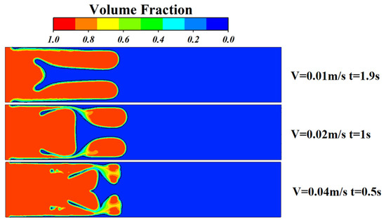
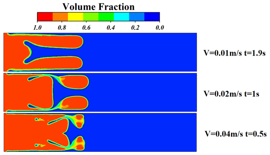
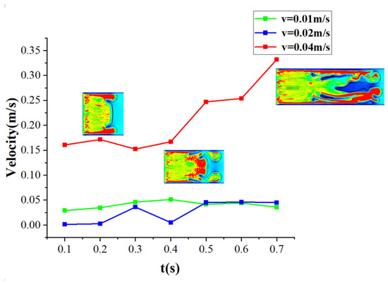
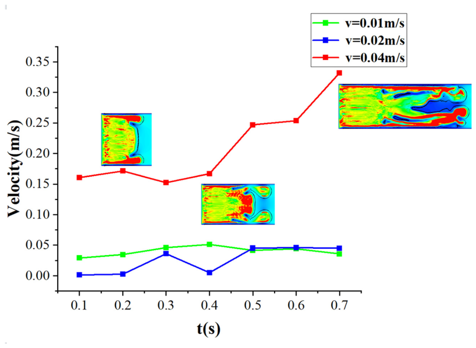
To further elucidate how the displacement rate governs the spatiotemporal evolution of the gas–liquid interface and the occurrence of tip splitting, the times required for the gas phase to reach the same streamwise position, S = 0.044 m, were compared together with the corresponding interfacial morphologies under different initial inlet velocities (Figure 13). At the low inlet velocity v = 0.01 m s−1 the gas phase required 1.9 s to reach this position. The displacement front exhibited pronounced spatial differentiation: the two slender wall-adjacent fingers propagated considerably farther than the central finger, with a longitudinal separation of up to 0.0285 m. When v = 0.02 m s−1, the time required to reach the same position decreased to 1.0 s, while the flow field retained a morphology characterized by the simultaneous advancement of three principal fingers. By contrast, at the high inlet velocity of v = 0.01 m s−1, the gas phase reached S = 0.044 m with only 0.5 s. Under this condition, the central finger underwent pronounced topological bifurcation, producing a complex front composed of four coexisting finger branches. The temporal evolution of the central-fingertip velocity shown in Figure 14 provides direct kinematic evidence for these morphological transitions. At v = 0.01 m s−1, represented by the blue curve in Figure 14, the central-fingertip velocity remained within a low and relatively stable range of 0.03 m s−1–0.05 m s−1. This persistently low propagation velocity indicates substantial momentum dissipation within the central pathway. A greater proportion of the system momentum was transferred toward the lower-resistance slender fingers adjacent to the upper and lower walls, directly accounting for the pronounced retardation of the central finger. When the initial inlet velocity increased to v = 0.02 m s−1, the central-fingertip velocity rose to approximately 0.04 m s−1 during the early stage t = 0.1 s–0.3 s. The resulting increase in the interfacial shear rate triggered a pronounced shear-thickening response. The associated increase in apparent viscosity created a viscous-resistance barrier, causing the velocity to decrease abruptly to approximately 0.01 m s−1 at t = 0.04 s. Following the subsequent redistribution of momentum and partial overcoming of the viscous resistance, the central finger received renewed forward momentum after t = 0.5 s. Its velocity recovered and stabilized at approximately 0.05 m s−1. This dynamic momentum balance ultimately maintained the simultaneous propagation of the three principal fingers. The red curve reveals the pronounced instability occur ring at v = 0.04 m s−1. After t = 0.03 m s−1, the central-front velocity departed markedly from its quasi-steady state and underwent a strong nonlinear increase, exceeding 0.33 m s−1 by t = 0.7 s. Such an abrupt local acceleration generated extremely high shear rates and viscous resistance ahead of the fingertip, which could no longer be accommodated by stable propagation through a single central pathway. Under sustained high-pressure driving, momentum within the central finger could not continue to be transmitted along its original path. The finger therefore underwent pronounced tip splitting to access new pathways of lower hydraulic resistance. This mechanism is consistent with the observed topological transition from three principal fingers to four coexisting finger branches.
Figure 13.
Gas–liquid interfacial morphologies when the leading air front reached S = 0.044 m. The inlet velocities of 0.01, 0.02, and 0.04 m s−1 correspond to t = 1.9, 1.0 and 0.5 s, respectively, no normalization was applied.
Figure 14.
Temporal evolution of the central-fingertip velocity for inlet velocities of 0.01, 0.02, and 0.04 m s−1, the colors represent the dimensional velocity magnitude in m s−1, from low values in blue to high values in red, the dimensional data were not normalized.
5. Influence of the Gap-Depth Gradient on the Air-Driven Displacement of a Shear-Thickening Fluid
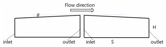
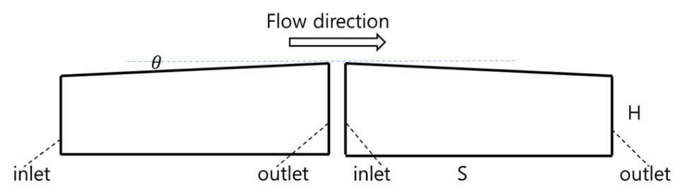
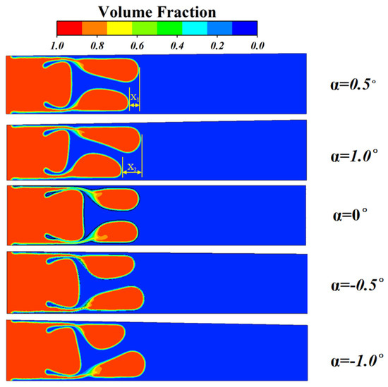
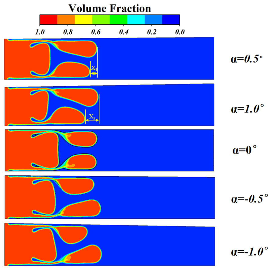
When the intrinsic physical properties of the fluids are fixed, the available means of controlling the evolution of the displacement system are generally limited. To overcome this constraint, the present study modifies the geometric confinement imposed by the walls. Specifically, a small gap-depth gradient was introduced into the Hele–Shaw cell to control the evolution of the classical viscous-fingering instability. The flow domain was designed as a tapered geometry along the primary flow direction [32]. Both positive and negative gap-depth gradients were considered (Figure 15), and the gradient remained constant along the primary flow direction in each case. The viscous-fingering patterns generated by air displacement of the shear-thickening non-Newtonian fluid under different gap-depth gradients were compared at t = 1 s. As shown in Figure 16, in the absence of a gap-depth gradient , the displacement front developed three symmetric finger pathways. The gas–liquid interface evolved relatively uniformly, and the advancing front exhibited stable propagation. Nevertheless, necking was observed at the roots of the two slender fingers adjacent to the upper and lower walls. Introducing a gap-depth gradient produced pronounced asymmetry in the viscous-fingering morphology. Under positive gradient of and , the geometric configuration caused the fingers to advance asymmetrically. At , the difference between the penetration depths of the slender fingers adjacent to the upper and lower walls was . When the taper angle increased to , this asymmetry became more pronounced, and the difference increased to . Meanwhile, the maximum penetration distance of the leading finger increased by a further . The opposite behavior was observed under negative gap-depth gradients. At , the slender finger adjacent to the upper wall propagated less deeply than that adjacent to the lower wall. When the magnitude of the taper angle increased to , the development of the upper slender finger was strongly compressed and restricted by the wall. Its penetration depth decreased by 2.1 × 10⁻³ m relative to that at . The fundamental mechanism underlying this gradient-induced asymmetry is that the change in channel geometry redistributes the local hydraulic resistance. Under the confined-flow conditions of a Hele–Shaw cell, hydraulic resistance is highly sensitive to variations in the gap depth, and the displacing fluid preferentially propagates along pathways of minimum resistance. Under a positive gap-depth gradient, the upward divergence of the upper wall enlarges the local gap and substantially reduces the hydraulic resistance. The low-viscosity air therefore preferentially converges toward and rapidly penetrates the slender pathway adjacent to the upper wall. Conversely, under a negative gap-depth gradient, the downward convergence of the upper wall produces a pronounced throttling effect and sharply increases the local hydraulic resistance. This geometric restriction redirects the displacing air toward the lower flat region, where the resistance is comparatively lower. These results demonstrate that, in heterogeneous channels containing a gap-depth gradient, wall-induced differences in hydraulic resistance determine the preferential flow pathway. Consequently, viscous fingers propagate preferentially toward regions with a larger gap depth and lower flow resistance.
Figure 15.
Geometric configurations of the Hele-Shaw cell with different gap-depth gradients.
Figure 16.
Gas–liquid interfacial morphologies at t = 1.0 for gap-depth gradients of 0.5°, 1.0°, 0°, −0.5°, and −1.0°. The colors identify the gas and liquid phases, and no normalization was applied.
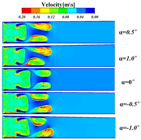
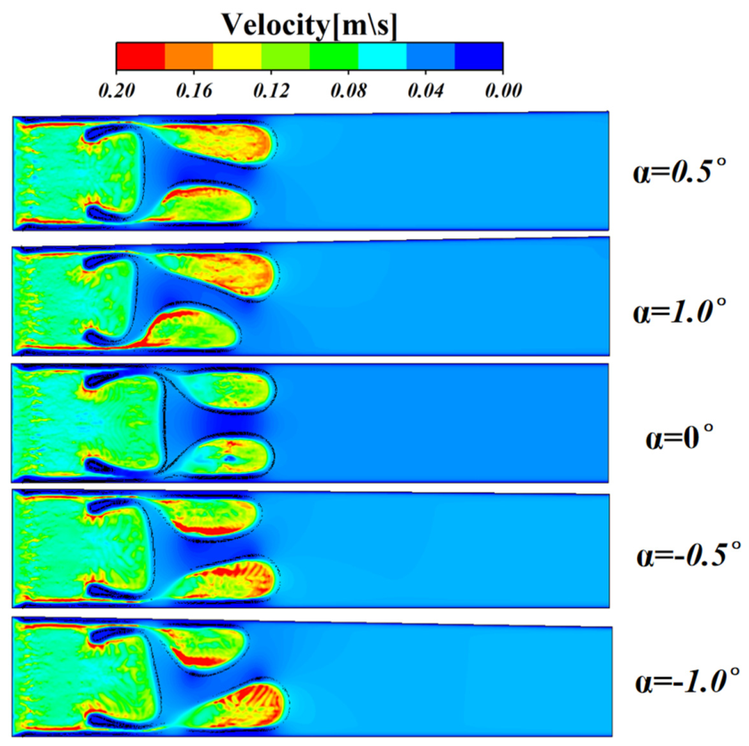
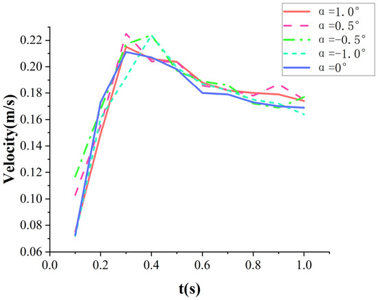
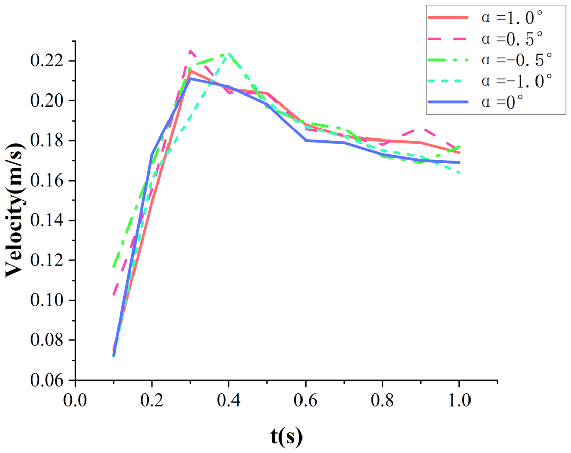
The spatial velocity distributions provide further direct hydrodynamic evidence for the evolution of the asymmetric fingering patterns described above. As shown in Figure 17, under a positive gap-depth gradient, the upward inclination of the upper wall substantially reduced the local hydraulic resistance. Following the path-of-least-resistance principle, the low-viscosity displacing gas preferentially converged toward the upper low-resistance region, producing an extensive high-velocity convective zone within the slender finger adjacent to the upper wall. This increase in local flow intensity directly accelerated the advancement of the gas–liquid interface. The maximum velocity at the front of the upper wall-adjacent finger reached 0.191 m s−1, resulting in a slender finger with a greater penetration distance. By contrast, under a negative gap-depth gradient, the converging configuration of the upper wall produced a pronounced throttling effect. The resulting high-resistance region forced the flow to undergo substantial redirection, causing the high-velocity core to shift asymmetrically toward the lower-resistance region adjacent to the lower flat wall. To further clarify the dynamic mechanism underlying the asymmetric finger profiles, the temporal velocities at the fronts of the longer slender fingers were extracted under the different gap-depth-gradient conditions. The corresponding results are presented in Figure 18 During the early stage of fingering development t < 0.4 s, the front velocities increased sharply under all conditions. However, differences in the local resistance distributions produced clearly distinguishable velocity profiles. Under positive gap-depth gradients, such as and , the reduction in hydraulic resistance caused by the inclined upper wall enabled the rapid and efficient release of fluid kinetic energy. The front velocity reached a peak of approximately 0.21 m s−1–0.22 m s−1 at t = 0.3 s. During the intermediate and later stages t > 0.6 s, the front velocity under the positive-gradient conditions decreased relatively slowly and remained at a comparatively high level of approximately 0.17 m s−1–0.18 m s−1. This sustained and intense local momentum transport provides direct quantitative support for the preceding observation that the displacing gas converges toward the lower-resistance region and accelerates interfacial advancement. In comparison, under negative gap-depth gradients, such as and , the pronounced throttling effect generated by the converging upper wall forced momentum redistribution within the flow field. This asymmetric transfer delayed the release of flow energy, as reflected by the velocity peaks occurring at approximately t = 0.4 s, later than those observed under the positive-gradient conditions. During the intermediate and later stages, kinetic-energy dissipation at the finger fronts intensified under both the negative- and zero-gradient conditions, resulting in a more pronounced downward decay of the velocity curves. The comparison of these kinematic data agrees closely with the path-of-least-resistance mechanism. From the perspective of the temporal response, the results demonstrate that the geometric gradient plays a determining role in controlling the penetration depth of the preferential flow pathway.
Figure 17.
Velocity magnitude contours at t = 1.0 for gap-depth gradients of 0.5°, 1.0°, 0°, −0.5°, and −1.0°. The colors represent the dimensional velocity magnitude in m s−1, from low values in blue to high values in red. No normalization was applied.
Figure 18.
Temporal evolution of the longer wall-adjacent fingertip velocity for gap-depth gradients of 0.5°, 1.0°, 0°, −0.5°, and −1.0°. The dimensional data were not normalized.
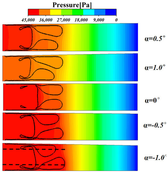
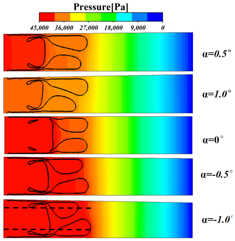
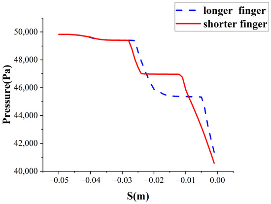
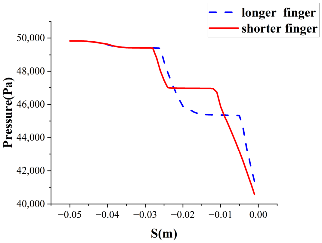
The pressure distributions shown in Figure 19 provide further physical insight into the asymmetric evolution of the viscous fingers. Under a positive gap-depth gradient, the geometric expansion of the lower part of the channel substantially reduced the local hydraulic resistance. The increased flow area also produced an overall resistance-reduction and pressure-relief effect. Consequently, at and , less energy was required to sustain fluid advancement, and the pressure within the main body of the displacing phase remained at the comparatively low level of approximately 4.0 × 10⁴–4.5 × 10⁴ Pa. Moreover, the isobars near the front of the slender finger were distinctly inclined downstream toward the upper wall. This distribution indicates that the low-resistance region near the upper wall enabled the upstream pressure energy to be transmitted more effectively toward the front of the upper slender finger. The resulting nonuniform distribution of the local pressure drop provided a stronger driving force for this finger, allowing it to develop a pronounced advantage in both length and width. By contrast, under a negative gap-depth gradient, convergence of the upper wall produced a strong throttling effect and caused substantial pressure loss near the front of the upper slender finger. Following the minimum-energy-dissipation principle, the high-pressure driving force was redirected toward the lower slender finger, where the hydraulic resistance was lower. More importantly, the pressure contours provide direct evidence of a pressure-shielding effect during interfacial destabilization. As shown in Figure 20, the pressure profiles extracted along the two dashed finger-propagation pathways marked in Figure 17 further elucidate the mechanism underlying pressure shielding. In the common upstream region, the two pressure profiles nearly overlap, indicating that the two branches are initially subjected to comparable pressure driving forces. As interfacial asymmetry develops, however, the pressure distributions gradually diverge. A pronounced low-gradient plateau emerges along the shorter-finger pathway, suggesting that, despite the relatively high absolute pressure maintained in this region, the upstream pressure cannot establish a sufficiently strong streamwise pressure gradient near the shorter-finger tip. By contrast, the principal pressure drop along the longer-finger pathway is shifted farther downstream and concentrated within a shorter region near its tip. Estimates from the pressure profiles yield an average tip pressure gradient of approximately 1.0 MPa m−1 for the longer finger, compared with approximately 0.6 MPa m−1 for the shorter finger. The longer finger therefore experiences a stronger local pressure-driven force. Combined with the lower hydraulic resistance of the region through which it propagates, this enhanced pressure gradient enables the longer finger to attract a greater proportion of the flow and accelerate further. Meanwhile, the shorter finger enters a pressure-shielded zone characterized by a weak pressure gradient, thereby establishing a positive-feedback process involving the acceleration of the longer finger and the suppression of the shorter one.
Figure 19.
Gauge-pressure contours at t = 1.0 s for gap-depth gradients of 0.5°, 1.0°, 0°, −0.5°, and −1.0°. The colors represent the dimensional gauge pressure in Pa relative to the outlet pressure of 0 Pa. No normalization was applied. The black lines delineate the gas–liquid interfaces, whereas the horizontal black dashed lines in the α = −1.0° panel indicate the sampling paths used to extract the pressure profiles.
Figure 20.
Pressure distributions along the longer and shorter slender-finger pathways.
6. Conclusions
Three-dimensional numerical simulations were conducted to investigate the air-driven displacement of a shear-thickening fluid (STF) in a Hele–Shaw cell. The effects of interfacial tension, air-inlet velocity, and gap-depth gradient on viscous-fingering evolution were systematically examined. The principal conclusions are as follows.
- Interfacial tension governs finger topology and momentum redistribution. At the lowest interfacial tension (0.025 N m−1), weak capillary resistance could not counteract the intense local velocity fluctuations and steep pressure gradients. The resulting shear and extensional deformation induced pronounced necking at the roots of the wall-adjacent fingers, followed by pinch-off and bubble detachment. Increasing the interfacial tension to (0.055 N m−1) and (0.075 N m−1) strengthened capillary restoration and the Laplace pressure jump, attenuated localized high-pressure penetration, and smoothed the pressure gradient near the advancing front. These effects suppressed interfacial deformation and maintained continuous momentum transport, thereby preserving the topological integrity and smooth evolution of the fingers. Higher interfacial tension nevertheless intensified flow partitioning: the injected air was preferentially diverted through the lower-resistance wall-adjacent pathways, leaving an extensive near-stagnant region in the center. Consequently, the penetration depth of the central finger decreased monotonically with increasing interfacial tension.
- Air-inlet velocity controls the nonlinear destabilization and topological transition of the displacement front. At (v = 0.01 m s−1), energy dissipation remained relatively uniform, and the air advanced in a quasi-steady laminar regime. Increasing the inlet velocity to (0.02 m s−1–0.04 m s−1 sharply elevated the local shear rate at the gas–liquid interface and triggered a pronounced shear-thickening response, generating a high-viscosity resistance barrier ahead of the front. The resulting resistance heterogeneity forced momentum to redistribute toward pathways of lower hydraulic resistance. At v = 0.04 m s−1, this mechanism produced large-amplitude nonlinear velocity fluctuations and steep spatial pressure gradients. Under sustained high-pressure driving, momentum could no longer be transmitted effectively through a single finger. The air consequently penetrated the continuous STF interface, causing severe topological breakup, including tip splitting and fingering breakthrough. The resulting bypass flow disrupted the continuity of the displaced phase and generated numerous isolated pockets of residual STF.
- A small gap-depth gradient fundamentally reconfigures the spatial symmetry and dynamics of viscous fingering. The geometric gradient redistributed the local hydraulic resistance and induced asymmetric propagation along preferential pathways. Under a positive gap-depth gradient, channel expansion reduced the hydraulic resistance, promoted rapid momentum transfer, and directed the gas toward the low-resistance region. The dominant finger therefore reached its peak velocity earlier and maintained sustained momentum transport. Conversely, under a negative gradient, wall convergence generated a pronounced throttling effect. The resulting increase in local resistance delayed momentum release, intensified kinetic-energy dissipation, and forced asymmetric momentum redistribution. The geometric constraint also produced a distinct pressure-shielding effect: isobars concentrated around the dominant fingertip in the low-resistance region, providing a persistent driving pressure, whereas fingers in the high-resistance region entered a shielded, low-pressure-gradient zone and exhibited restricted growth. The coupled effects of resistance redistribution and pressure shielding ultimately governed asymmetric breakthrough and selected the longer preferential finger pathway.
Collectively, the present numerical results suggest that viscous fingering during the air-driven displacement of an STF is controlled by the coupled redistribution of capillary stresses, hydraulic resistance, pressure, and momentum. These findings provide qualitative guidance for understanding interfacial instability in confined displacement systems. From a broader engineering perspective, Zebida et al. [39] combined experiments, long-term regeneration tests, and CFD simulations to investigate flow behavior and optimize an industrial adsorption process, demonstrating the importance of integrating numerical modeling with material evaluation and process-scale validation. Although their application differs from the present study, it highlights the potential of CFD for relating local flow characteristics to process performance and supporting the optimization and scale-up of industrial systems.
However, the present conclusions are limited to the investigated parameter range and an idealized smooth-wall Hele–Shaw geometry. The STF was modeled as a homogeneous power-law continuum; therefore, particle migration, sedimentation, concentration variations, particle-scale jamming, wall roughness, and wall deformation were not explicitly considered. Gravity was neglected to isolate the effects of capillarity, shear-thickening rheology, and geometric confinement. Moreover, uncertainties associated with numerical resolution, interface reconstruction, constitutive parameters, and the lack of quantitative validation may remain. Therefore, the predicted pressure levels and instability thresholds should not be regarded as universal or directly extrapolated to industrial systems. Future work should include quantitative experimental validation, broader parameter ranges, realistic porous geometries, particle-transport and gravitational effects, and process-level optimization to improve the practical relevance of the model.
Author Contributions
Conceptualization, Q.W. and Z.Q.; methodology, Q.W.; software, S.-K.L. and Z.Q.; validation, S.-K.L. and Q.W.; formal analysis, H.G. and Q.W.; investigation, Y.-T.W. and Q.W.; resources, S.-K.L.; data curation, H.G.; writing—original draft preparation, Q.W. and Y.-T.W.; writing—review and editing, S.-K.L. and Z.Q.; visualization, Q.W.; project administration, Z.Q.; funding acquisition, S.-K.L. All authors have read and agreed to the published version of the manuscript.
Funding
This research was supported by the Shandong Provincial Natural Science Foundation under Grants ZR2024ME088, ZR2026MS0818 and ZR2025QC573, the Material and Components Technology R&D Project of the Korea Ministry of Trade, Industry and Energy (Grant No: RS-2024-00434150).
Data Availability Statement
The original contributions presented in this study are included in the article. Further inquiries can be directed to the corresponding author.
Conflicts of Interest
The authors declare no conflicts of interest.
References
- Saffman, P.G.; Taylor, G.I. The penetration of a fluid into a porous medium or Hele–Shaw cell containing a more viscous liquid. Proc. R. Soc. A Math. Phys. Eng. Sci. 1958, 245, 312–329. [Google Scholar] [CrossRef] [Scilit]
- Singh, A.; Singh, Y.; Pandey, K.M. Viscous fingering instabilities in radial Hele–Shaw cell: A review. Mater. Today Proc. 2020, 26, 760–762. [Google Scholar] [CrossRef] [Scilit]
- Pouplard, A.; Tsai, P.A. Controlling viscous fingering instabilities of complex fluids. Sci. Rep. 2024, 14, 2338. [Google Scholar] [CrossRef] [Scilit] [PubMed]
- Yan, Y.; Wei, M.; Huang, Z. Review on shear thickening fluid and its applications in vibration reduction. Mater. Res. Express 2024, 11, 012001. [Google Scholar] [CrossRef] [Scilit]
- Mora, G.H.S.; Moreno, R.B.Z.L. Rheology and statistical optimization of a shear-sensitive fluid as a treatment for circulation loss control. J. Pet. Sci. Eng. 2021, 205, 108830. [Google Scholar] [CrossRef] [Scilit]
- Singh, P.; Mondal, S. Viscous fingering to fracturing transition in Hele–Shaw flow of shear-thickening fluid. Phys. Fluids 2023, 35, 064116. [Google Scholar] [CrossRef] [Scilit]
- Fasmin, F.; Sodiq, A.; Mohapatra, L.; Flox, C.; Biendicho, J.J.; Bhat, Z.M.; Morante, J.R.; Merzougui, B.; Qamar, M. Slurry-based electrochemical flow systems: Fundamentals, performance, and engineering. ACS Electrochem. 2025, 1, 1945–1971. [Google Scholar] [CrossRef] [Scilit]
- He, M.; Zhou, X.; Liu, J. Latest progress and challenges associated with lithium-ion semi-solid flow batteries: A critical review. Phys. Chem. Chem. Phys. 2024, 26, 24735–24752. [Google Scholar] [CrossRef] [Scilit] [PubMed]
- Mukuhira, Y.; Goto, R.; Watanabe, N.; Sueyoshi, K.; Takuma, K.; Zhang, R.; Tian, T.; Sokolovski, V.; Naoi, M.; Arai, Y.; et al. Creating multidirectional fractures through particle jamming. Int. J. Rock Mech. Min. Sci. 2025, 188, 106051. [Google Scholar] [CrossRef] [Scilit]
- Singh, P.; Lalitha, R.; Mondal, S. Saffman–Taylor instability in a radial Hele–Shaw cell for a shear-dependent rheological fluid. J. Non-Newton. Fluid Mech. 2021, 294, 104579. [Google Scholar] [CrossRef] [Scilit]
- Palak; Parmar, V.R.S.; Chanda, S.; Bandyopadhyay, R. Emergence of transient reverse fingers during radial displacement of a shear-thickening fluid. Colloids Surf. A Physicochem. Eng. Asp. 2023, 662, 130926. [Google Scholar] [CrossRef] [Scilit]
- Lautenschlaeger, M.P.; Prifling, B.; Kellers, B.; Weinmiller, J.; Danner, T.; Schmidt, V.; Latz, A. Understanding electrolyte filling of lithium-ion battery electrodes on the pore scale using the lattice Boltzmann method. Batter. Supercaps 2022, 5, e202200090. [Google Scholar] [CrossRef] [Scilit]
- Shodiev, A.; Primo, E.; Arcelus, O.; Chouchane, M.; Osenberg, M.; Hilger, A.; Manke, I.; Li, J.; Franco, A.A. Insight on electrolyte infiltration of lithium-ion battery electrodes by means of a new three-dimensional-resolved lattice Boltzmann model. Energy Storage Mater. 2021, 38, 80–92. [Google Scholar] [CrossRef] [Scilit]
- Zhao, B.; Mohanty, K.K. Effect of wettability on immiscible viscous fingering in porous media. J. Pet. Sci. Eng. 2019, 174, 738–746. [Google Scholar] [CrossRef] [Scilit]
- Zhao, W.; Wang, S.; Zhou, Y.; Wang, M.; Yang, L.; Liu, J.; Wang, L.; Zhu, P. Viscous fingering instability in one-end-lifted Hele–Shaw cells for producing three-dimensional hierarchical structures. J. Colloid Interface Sci. 2025, 699, 138202. [Google Scholar] [CrossRef] [Scilit] [PubMed]
- Bakharev, F.; Campoli, L.; Enin, A.; Matveenko, S.; Petrova, Y.; Tikhomirov, S.; Yakovlev, A. Numerical investigation of viscous fingering phenomenon for raw field data. Transp. Porous Media 2020, 132, 443–464. [Google Scholar] [CrossRef] [Scilit]
- Fontana, J.V.; Cuttle, C.; Pihler-Puzović, D.; Hazel, A.L.; Juel, A. Peeling fingers in an elastic Hele–Shaw channel. J. Fluid Mech. 2024, 985, A1. [Google Scholar] [CrossRef] [Scilit]
- Abderrahmane, H.A.; Rabbani, S.; Sassi, M. Inertia effects in the dynamics of viscous fingering of miscible fluids in porous media: Circular Hele–Shaw cell configuration. Energies 2021, 14, 6432. [Google Scholar] [CrossRef] [Scilit]
- Anjos, P.H.A.; Zhao, M.; Lowengrub, J.; Bao, W.; Li, S. Controlling fingering instabilities in Hele–Shaw flows in the presence of wetting film effects. Phys. Rev. E 2021, 103, 063105. [Google Scholar] [CrossRef] [Scilit] [PubMed]
- Kargozarfard, Z.; Riazi, M.; Ayatollahi, S. Viscous fingering and its effect on areal sweep efficiency during waterflooding: An experimental study. Pet. Sci. 2019, 16, 105–116. [Google Scholar] [CrossRef] [Scilit]
- Rabbani, H.S.; Or, D.; Liu, Y.; Lai, C.-Y.; Lu, N.B.; Datta, S.S.; Stone, H.A.; Shokri, N. Suppressing viscous fingering in structured porous media. Proc. Natl. Acad. Sci. USA 2018, 115, 4833–4838. [Google Scholar] [CrossRef] [Scilit] [PubMed]
- Sharma, V.; Pramanik, S.; Chen, C.-Y.; Mishra, M. A numerical study on reaction-induced radial fingering instability. J. Fluid Mech. 2019, 862, 624–638. [Google Scholar] [CrossRef] [Scilit]
- Nand, S.; Sharma, V.; Das, S.K.; Padhee, S.S.; Mishra, M. Effect of Hele–Shaw cell gap on radial viscous fingering. Sci. Rep. 2022, 12, 18967. [Google Scholar] [CrossRef] [Scilit] [PubMed]
- Lee, Y.H.; Wang, J.; Gates, I.D. Effects of dilute low molecular weight poly(ethylene oxide) solutions in immiscible radial viscous fingering instabilities. Phys. Fluids 2023, 35, 084101. [Google Scholar] [CrossRef] [Scilit]
- Ahmadikhamsi, S.; Golfier, F.; Oltean, C.; Lefèvre, E.; Bahrani, S.A. Impact of surfactant addition on non-Newtonian fluid behavior during viscous fingering in a Hele–Shaw cell. Phys. Fluids 2020, 32, 012103. [Google Scholar] [CrossRef] [Scilit]
- Wang, M.; Xiong, Y.; Liu, L.; Peng, G.; Zhang, Z. Lattice Boltzmann simulation of immiscible displacement in porous media: Viscous fingering in a shear-thinning fluid. Transp. Porous Media 2019, 126, 411–429. [Google Scholar] [CrossRef] [Scilit]
- Singh, P.; Mondal, S. Control and suppression of viscous fingering displacing non-Newtonian fluid with time-dependent injection strategies. Phys. Fluids 2022, 34, 114117. [Google Scholar] [CrossRef] [Scilit]
- Wu, Y.-T.; Qin, Z.; Ma, H.; Lyu, S.-K. Numerical study on the characteristics of viscous fingering during the displacement process of non-Newtonian fluid. PLoS ONE 2024, 19, e0309176. [Google Scholar] [CrossRef]
- Parmar, V.R.S.; Bandyopadhyay, R. Permeability heterogeneity and bulk linear elasticity of displaced clay suspensions determine interfacial pattern morphologies in Hele–Shaw experiments. New J. Phys. 2025, 27, 124402. [Google Scholar] [CrossRef] [Scilit]
- Dufresne, A.P.; Ball, T.V.; Balmforth, N.J. Viscoplastic Saffman–Taylor fingers with and without wall slip. J. Non-Newton. Fluid Mech. 2023, 312, 104970. [Google Scholar] [CrossRef] [Scilit]
- Adriazola, J.; Gu, B.; Cummings, L.J.; Kondic, L. Fractal dimension of non-Newtonian Hele–Shaw flow subject to Saffman–Taylor instability. Phys. Rev. E 2024, 110, 065107. [Google Scholar] [CrossRef] [Scilit] [PubMed]
- Giljarhus, K.E.T.; Skadsem, H.J.; Barrouillet, B. Numerical modeling of fluid displacement in Hele–Shaw cells: A gap-averaged approach for power-law and Newtonian fluids. Rheol. Acta 2025, 64, 117–132. [Google Scholar] [CrossRef] [Scilit]
- Anjos, P.H.A.; Miranda, J.A. Radial viscous fingering: Wetting film effects on pattern-forming mechanisms. Phys. Rev. E 2013, 88, 053003. [Google Scholar] [CrossRef] [Scilit] [PubMed]
- Wu, Y.-T.; Lyu, S.-K.; Qin, Z.; Zhang, J.; Qiao, H. Research on interfacial instability control during CO2 displacement of non-Newtonian fluids. Lubricants 2025, 13, 478. [Google Scholar] [CrossRef] [Scilit]
- Kagei, N.; Kanie, D.; Kawaguchi, M. Viscous fingering in shear thickening silica suspensions. Phys. Fluids 2005, 17, 054103. [Google Scholar] [CrossRef] [Scilit]
- Singh, A.; Pandey, K.M.; Singh, Y. CFD analysis of viscous fingering in Hele–Shaw cell for air–glycerin system. Mater. Today Proc. 2021, 45, 6381–6385. [Google Scholar] [CrossRef] [Scilit]
- Al-Housseiny, T.T.; Stone, H.A. Controlling viscous fingering in tapered Hele–Shaw cells. Phys. Fluids 2013, 25, 092102. [Google Scholar] [CrossRef] [Scilit]
- Oliveira, R.M.; Abedi, B.; Santos, L.F.; Câmara, P.S.; de Souza Mendes, P.R. Similarity characteristics in the morphology of radial viscous fingers. Phys. Fluids 2023, 35, 042114. [Google Scholar] [CrossRef] [Scilit]
- Zebida, M.; Gherdaoui, C.E.; Alaoui, C.; Bouchikhi, N.; Zaoui, F.; Maschke, U.; Sehmi, A.; Oumeddour, H.; Gherdaoui, S.; Aldoori, H.; et al. Toward sustainable transformer oil recycling: Comparative efficacy of adsorbents and CFD simulation analysis. Sep. Purif. Technol. 2026, 380, 135509. [Google Scholar] [CrossRef] [Scilit]

Disclaimer/Publisher’s Note: The statements, opinions and data contained in all publications are solely those of the individual author(s) and contributor(s) and not of MDPI and/or the editor(s). MDPI and/or the editor(s) disclaim responsibility for any injury to people or property resulting from any ideas, methods, instructions or products referred to in the content. |
© 2026 by the authors. Licensee MDPI, Basel, Switzerland. This article is an open access article distributed under the terms and conditions of the Creative Commons Attribution (CC BY) license.