


Abstract
Poly(vinylidene fluoride) (PVDF)-based solid polymer electrolytes (SPEs) are attractive candidates for high-safety lithium metal batteries, yet their high crystallinity and restricted segmental motion impede Li+ transport and long-term interfacial stability. Herein, a cross-linked product (PEPA) was synthesized from poly(acrylic acid) (PAA) and poly(ethylene glycol) (PEG) through an EDC/NHS coupling reaction, and subsequently introduced into a PVDF–LiTFSI matrix to prepare quasi-solid polymer electrolyte membranes. FTIR and XRD results reveal a reduced degree of crystallinity together with an increased amorphous fraction, while SEM/EDS and TGA indicate a more compact and uniform membrane morphology and improved thermal stability. The optimized PEPA10SPE exhibits a high ionic conductivity of 1.5 × 10⁻³ S cm−1 at 25 °C (3.1 × 10⁻³ S cm−1 at 75 °C) and a markedly enhanced Li+ transference number of 0.70, compared with 0.35 for the pristine PVDFSPE, together with a broadened electrochemical stability window (oxidation onset delayed from approximately 4.4 V to 5.3–5.4 V). Consequently, the Li|PEPA10SPE|LiFePO4 cell delivers an initial discharge capacity of approximately 150 mAh g−1 with a capacity retention of nearly 85% after 500 cycles, while the Li|PEPA10SPE|Li symmetric cell cycles stably for more than 3000 h at 0.2 mA cm−2. This work demonstrates that cross-linking-mediated regulation of the amorphous phase and the Li+ coordination environment is an effective route to high-performance PVDF-based quasi-solid polymer electrolytes for lithium metal batteries.
1. Introduction
Against the backdrop of accelerated global energy transition and the continuous advancement of low-carbon development strategies, the development of high-safety energy storage systems has become an important research focus in the field of electrochemical energy storage [1,2]. With the rapid development of large-scale energy systems, battery systems not only need to achieve higher energy density but also meet the requirements for long-term cycling stability [3,4]. Solid-state electrolytes have garnered widespread attention due to their excellent thermal stability and intrinsic safety characteristics [5,6,7]. Developing a stable and efficient solid-state electrolyte system to suppress dendrite growth and improve interfacial stability has become a key technological strategy [8,9].
Solid polymer electrolytes (SPEs) are particularly attractive because of their favorable processability and interfacial adaptability, which enable intimate electrode–electrolyte contact and thereby alleviate interfacial contact limitations [10,11]. Nevertheless, ion conduction in polymer matrices is strongly governed by their crystallization characteristics, chain conformation, and microphase organization, since these structural features determine the connectivity and accessibility of Li+ transport pathways. As a consequence, improvements in ionic transport are often accompanied by compromises in mechanical robustness, making it challenging to simultaneously optimize both properties [12,13]. Among the polymer hosts investigated for SPEs, poly(vinylidene fluoride) (PVDF) has received considerable attention owing to the highly polar nature of its molecular chains and its relatively high dielectric constant, both of which are beneficial for lithium-salt dissolution and ionic dissociation [14,15]. However, Li+ migration within PVDF can be impeded by its high degree of crystallinity and relatively restricted segmental motion. Accordingly, structural modification of the PVDF matrix to promote ion transport while preserving electrochemical stability has emerged as an important strategy.
In solid polymer electrolytes, mobile Li+ species are predominantly produced through the dissociation of dissolved lithium salts [16,17]. This dissociation process is strongly influenced by the coordination interactions established between Li+ and polar functionalities along the polymer chains. In particular, electron-rich atoms, such as O and F, can act as coordination sites through their lone-pair electrons, thereby stabilizing Li+ and facilitating the separation of lithium salts into ionic species [18]. Consequently, the extent of salt dissociation governs the population of mobile Li+ carriers and thus plays an important role in determining the ionic conductivity of the electrolyte [19]. Following dissociation, Li+ transport proceeds through successive exchanges among neighboring coordination sites, which can be described as a coordination-site hopping process. Because such transitions require continuous reorganization of the local coordination environment, they are closely coupled with conformational changes and segmental motion of the polymer chains [20]. Enhanced segmental mobility therefore promotes the dynamic association and dissociation of Li+ with different coordination sites, lowers the kinetic constraints on site-to-site transfer, and ultimately facilitates long-range ion migration through the polymer matrix.
Polymer electrolytes generally contain both crystalline and amorphous domains, whose distinct structural characteristics exert different influences on ion transport. Owing to their relatively large free volume and enhanced segmental mobility, amorphous regions provide more favorable environments for ionic migration and are therefore commonly regarded as the dominant ion-conduction pathways [21]. In contrast, the highly ordered chain packing and limited molecular motion within crystalline domains tend to restrict the rearrangement of coordination sites, thereby impeding ion transport [22]. Accordingly, the degree of crystallinity plays an important role in determining the overall ionic conductivity of polymer electrolytes. Although an increase in crystallinity can contribute to improved mechanical robustness and thermal stability, it is usually accompanied by reduced segmental dynamics and less efficient ion migration. By comparison, increasing the proportion of the amorphous phase can facilitate ionic conduction by promoting chain mobility, but excessive suppression of crystallinity may weaken the mechanical integrity of the electrolyte membrane [23]. Consequently, achieving an appropriate balance between ion-transport capability and mechanical stability remains a fundamental challenge in the design of solid polymer electrolytes.
Therefore, an ideal polymer electrolyte matrix should promote lithium salt dissociation while avoiding excessive constraints on Li+ migration, enabling dynamic exchange between different coordination sites [24,25,26]. Owing to the highly polar nature of C–F bonds, PVDF provides a polar local environment that can increase the dielectric constant of the polymer matrix, thereby facilitating the dissociation of lithium salts. Nevertheless, Li+ transport may still be constrained by the relatively restricted segmental motion of PVDF chains, since ion migration in polymer electrolytes is closely associated with polymer-chain dynamics. Consequently, the incorporation of functional moieties that can tailor the local coordination environment and/or promote segmental mobility, without compromising the structural integrity of the polymer matrix, is regarded as an effective strategy for enhancing ionic transport in PVDF-based solid polymer electrolytes.
In this work, a chemically cross-linked network is introduced into the PVDF–PAA system to tailor the organization and interactions of polymer chains at the molecular level. Such network regulation is expected to improve the robustness and stability of the electrolyte membrane while simultaneously optimizing its microphase morphology. When an appropriate degree of cross-linking is achieved, excessive segmental motion can be restrained without completely suppressing the local chain dynamics required for ion transport. Meanwhile, the resulting confined network domains may contribute to the preservation of continuous and structurally stable Li+-transport pathways. Cross-linking can also alter the local packing and mobility of polymer segments, which may promote a more homogeneous distribution of amorphous domains while limiting excessive crystallization. Furthermore, polar functionalities and coordination environments associated with the cross-linked network may participate in the reversible coordination of Li+, thereby modulating local ion–polymer interactions and facilitating the establishment of favorable Li+ migration pathways [27]. Through these coupled effects, the cross-linked architecture is anticipated to provide a more balanced combination of mechanical stability and ion-transport capability in the PVDF–PAA electrolyte system. This study aims to systematically investigate the effects of cross-linked structures on crystallinity, restricted segmental motion, and ion transport pathway continuity by combining structural characterization with electrochemical performance evaluation.
2. Experimental Section
2.1. Preparation of the Cross-Linked Product of PAA and PEG (PEPA)
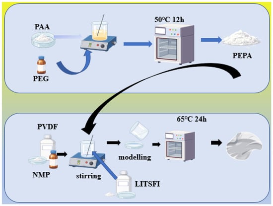
The synthesis processes of PEPA are shown in Figure 1. Polyacrylic acid (PAA, 1 g, Aladdin) was dissolved in 30 mL of N-methylpyrrolidone (NMP, Macklin), followed by stirring for 30 min. To activate the carboxyl groups of PAA, 1-ethyl-3-(3-dimethylaminopropyl)carbodiimide hydrochloride (EDC, Sinopharm Chemical Reagent) and N-hydroxysuccinimide (NHS, Sinopharm Chemical Reagent) were introduced into the previously prepared PAA solution, and the resulting mixture was continuously stirred for 30 min. The mass ratio of EDC: NHS is 1:1.
Figure 1.
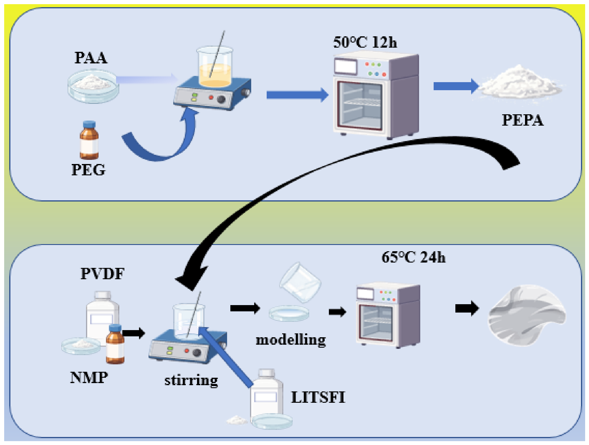
Schematic Illustration of the PEPA power and PEPA SPE.
Meanwhile, polyethylene glycol (PEG, Aladdin) was dissolved in 15 mL of NMP and stirred for 24 h to obtain a homogeneous PEG solution. The PEG solution was subsequently added dropwise to the EDC/NHS-activated PAA solution, after which the reaction mixture was further stirred for 4 h. Upon completion of the reaction, the resulting product was thoroughly washed with anhydrous ethanol and collected by suction filtration to remove residual unreacted species and reaction byproducts.
The cross-linked product PEPA was subsequently dried under vacuum at 50 °C for 12 h to remove residual solvents.
2.2. Preparation of the Quasi-Solid Polymer Electrolyte Membrane
The preparation process is illustrated in Figure 1. Polyvinylidene fluoride (PVDF HSV600, Mw = 600,000, Arkema) was dissolved in N-methyl-2-pyrrolidone (NMP) and magnetically stirred for 48 h. The mass ratio of PVDF:NMP is 1 g:18 mL. The cross-linked product PEPA was added, and the mixture was continuously stirred magnetically for 6 h. After the solution was cooled, it was transferred into an argon-filled glovebox, where 0.8 g of lithium bis(trifluoromethanesulfonyl)imide (LiTFSI,99%, Aladdin) was added, followed by magnetic stirring for 24 h under an argon atmosphere. The obtained homogeneous solution was cast onto a Petri dish, followed by drying in a vacuum oven at 65 °C for 24 h to remove the solvent, yielding a flexible quasi-solid-state polymer electrolyte membrane.
Samples membrane without PEPA addition was denoted as PVDF-SPE, whereas those containing 5%, 10%, and 15% PEPA were labeled PEPA5SPE, PEPA10SPE, and PEPA15SPE, respectively.
2.3. The Preparation of Electrodes
LiFePO4 (LFP, YOKO (China)), PVDF, and acetylene black (AC, YOUMENG (China, Chemical pure)) were homogeneously blended, after which an appropriate amount of N-methyl-2-pyrrolidone (NMP) was introduced as the solvent. The normal mass ratio of LFP:PVDF:AC was of 85:10:5. The resulting mixture was processed in a planetary mixer for 5 h until a homogeneous cathode slurry was obtained. Subsequently, the freshly prepared slurry was uniformly cast onto aluminum foil using a doctor blade with a gap of 150 µm. The coated aluminum foil was then dried under vacuum at 110 °C for 12 h to remove the residual solvent. After drying, circular electrodes with a diameter of 12 mm were punched from the coated foil, with the LiFePO4 mass loading maintained at approximately 1.13 mg cm−2. The resulting LFP cathodes were weighed and subsequently subjected to an additional vacuum-drying treatment at 60 °C. Finally, the LFP cathodes were transferred to and stored in an argon-filled glovebox, where the H2O and O2 concentrations were both maintained below 0.01 ppm, until further use.
2.4. Assembly of Coin Cells
The sample CR2025 coin cells were assembled in a glovebox. A reverse stacking configuration was adopted, in which the negative case served as the current-collecting substrate for the cathode. The cell components were then arranged sequentially from bottom to top in the following order: cathode, membrane, lithium metal anode, spacer, and spring. After all components had been properly positioned, the positive case was placed on top, and the assembled cell was hermetically sealed using a crimping machine (can-sea0a-0001es, Canrd).
2.5. Characterizations of Samples
The morphology and elemental distribution of the as-prepared solid polymer electrolyte (SPE) membranes were characterized by scanning electron microscopy (SEM, Phenomenon LE, Phenomworld, The Netherlands). Fourier-transform infrared (FTIR) spectroscopy was subsequently performed by Nicolet IS50 spectrometer (Thermo Fisher Scientific USA). The crystalline phase structures of the SPE membranes were investigated by a PANalytical X’Pert PXRD diffractometer (The Netherlands). To elucidate the surface chemistry of the SEI formed on the anode, Kratos XSAM 800 (Kratos Analytical Ltd., a subsidiary of Shimadzu Corporation, U,Al Kα radiation (144 W, 12 mA, 12 kV)) was employed to determine its elemental composition and corresponding chemical states. In addition, the thermal stability of the polymer samples was evaluated by thermogravimetric analysis (TGA, METTLER TGA2, METTLER TOLEDO, Switzerland).
The prepared samples were subjected to a 180° peel test using a universal material testing machine (LR5KPlus Lloyd, Lloyd Instruments, AMETEK, UK) to visually assess the adhesion strength between the electrode material and copper foil in different samples. The testing procedure is as follows: The prepared slurry was uniformly coated onto the current collector copper foil, dried in a vacuum oven, and then cut into rectangular pieces measuring approximately 40 mm in length and 20 mm in width. The side coated with the material was then pressed onto a 3 M tape and firmly adhered, while the other side of the tape was pressed tightly against a glass slide. The test parameters were set as follows: peel rate of 40 mm·min−1.
2.6. Electrochemical Performance Tests
The electrochemical properties of the quasi-solid polymer electrolyte (QSPE) membranes were investigated (CHI 660E, Chenhua, Shanghai, China). Electrochemical impedance spectroscopy (EIS) was first performed on the impedance cells to determine the bulk resistance of the electrolyte. Based on the obtained resistance, the ionic conductivity of the SPE membrane was calculated according to Equation (1):
where L denotes the thickness of the QSPE, Re is the ohmic resistance obtained from the impedance measurement, and (S) represents the effective contact area between the QSPE and the electrode.
The Li+ transference number (tLi+) was determined by combining chronoamperometry with EIS measurements using Li//SPE//Li symmetric cells. A constant polarization voltage (ΔV) of 10 mV was applied during the chronoamperometric measurement, while impedance spectra were recorded both before and after polarization. The tLi+ was subsequently calculated using the Bruce–Vincent–Evans equation:
where (I0) and (Is) correspond to the initial and steady-state currents, respectively, and (R0) and (RS) denote the interfacial resistances between the SPE membrane and the lithium electrodes before and after polarization, respectively.
The electrochemical stability window of the QSPE membrane was examined by linear sweep voltammetry (LSV) using Li//SPE//SS cells over a potential range of 2–6 V. In addition, lithium plating/stripping measurements were carried out to assess the capability of the electrolyte membrane to sustain reversible Li deposition and dissolution and to suppress dendritic lithium growth. The rate-dependent electrochemical performance of the LFP-based cells was further evaluated by galvanostatic charge–discharge measurements using a NEWARE BTS battery testing system (CT-4008T, NEWARE, Shenzhen). These measurements were conducted between 2.5 and 4.0 V at different current densities to investigate the cycling behavior of the cells under various rate conditions.
3. Results and Discussion
3.1. Characterizations
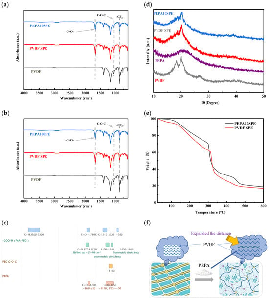
FTIR spectra were employed to confirm the formation of the PAA/PEG cross-linked. The infrared spectra of PVDF power, PEG and PEPA power are shown in Figure 2a and the infrared spectra of PVDF, PVDFSPE and PEPA10SPE are shown in Figure 2b.
Figure 2.
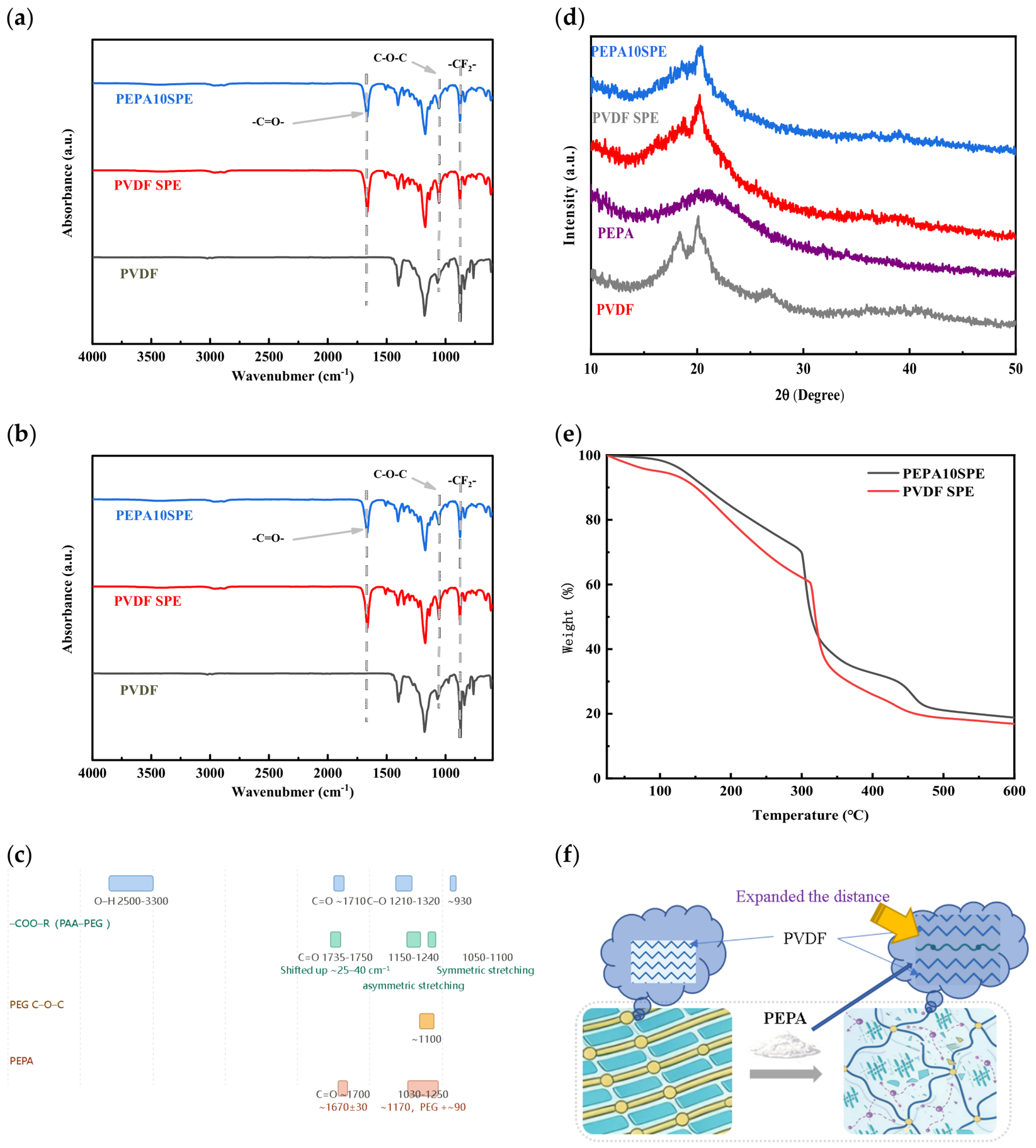
(a) FTIR spectra of PVDF power, PEG and PEPA power; (b) the infrared spectra of PVDF power, PVDFSPE and PEPA5SPE; (c) comparison of infrared characteristic peaks of ester bonds and carboxylic acids (4000–600 cm−1); (d) XRD patterns of PVDF, PEPA, PVDFSPE, and PEPA10SPE; (e) TGA curves of PVDFSPE and PEPA10SPE; (f) schematic diagrams showing the mechanisms of doping with PEPA.
The FTIR spectrum of PVDF power exhibits characteristic absorption bands at 840 and 1187 cm−1, which are assigned to the asymmetric stretching vibrations of the –CH2– and –CF2– groups, respectively. For the pristine PEG polymer, a prominent absorption band located at approximately 1100 cm−1 originates from the stretching vibration of the C–O–C linkage. After the incorporation of PAA, the presence of PAA segments is evidenced by the carbonyl absorption band appearing near 1700 cm−1, which can be attributed to the C=O stretching vibration of the carboxylic groups in poly(acrylic acid). And after the incorporation of PAA, the hydroxyl-related absorption (PEG) becomes weaker than that observed for pristine PEG, accompanied by noticeable variations in the carbonyl region. These spectral changes indicate that the local chemical environment of the corresponding functional groups has been altered, which is consistent with the formation of intermolecular interactions and/or a cross-linked structure between PEG and PAA.
The conversion of carboxylic acid groups into ester linkages is accompanied by systematic and diagnostic changes in the mid-infrared spectrum (Figure 2c). Some spectral features are of primary importance (Table 1).
Table 1.
Infrared criterion analysis of the difference between O=C–O–R and O=C–OH.
Broadening, intensification and multi-component character of the C–O–C envelope: PEG exhibits a single strong band with an extracted maximum at ~1074 cm−1 (i.e., the commonly cited ~1100 cm−1 ether band). In PEPA, this region expands into a broad envelope spanning 1030–1250 cm−1, with the maximum displaced to ~1170 cm−1 (approximately 90–100 cm−1 above that of PEG) and with resolvable components at ~1259, ~1170 and ~1050 cm−1. This pattern is consistent with the superposition of the PEG ether C–O–C band (~1100 cm−1), the ester asymmetric C–O stretch (1150–1240 cm−1) and the ester symmetric C–O stretch (1050–1100 cm−1), and thus constitutes strong evidence for ester bond formation [28].
Position of the carbonyl band: The carbonyl absorption of PEPA is extracted at ~1670 ± 30 cm−1, which agrees with the value of ~1700 cm−1 stated. Its relatively low wavenumber indicates that the band is not a pure ester carbonyl but rather a superposition of residual carboxylic C=O (~1710 cm−1) and newly formed ester C=O (~1735 cm−1), appearing as a broadened band or shoulder [29].
Absence of the broad O–H envelope in PEPA: No pronounced absorption is observed between 2500 and 3300 cm−1, in contrast to the broad O–H envelope expected for a carboxylic acid. This is consistent with consumption of –COOH during esterification [28,29].
The pristine PVDF membrane exhibits characteristic absorption bands associated with CH2 and CF2 groups (Table 2). After introducing PEG, a new absorption band around 1100 cm−1 corresponding to the C–O–C stretching vibration becomes evident, confirming the presence of PEG chains. For the PEPA10SPE sample, an additional peak near 1700 cm−1 attributed to the C=O stretching vibration of carboxyl groups in PAA/LITFSI appears. Meanwhile, the retention of the CF2 characteristic peaks demonstrates that the PVDF framework remains intact. The enhanced C–O–C signal together with the appearance of C=O absorption suggests the formation of a PAA/PEG cross-linked network within the PVDF matrix.
Table 2.
Infrared spectroscopy analysis of PVDF power and different membranes.
Figure 2d shows the XRD patterns of PVDF, PEPA, and the corresponding composite electrolyte membranes. Pure PVDF exhibits distinct diffraction peaks at approximately 18–20°, corresponding to its characteristic crystalline structures. The PEPA sample exhibits a broad diffuse peak as the dominant feature, with no sharp diffraction peaks observed, indicating low crystallinity and a predominantly amorphous structure. Compared with pure PVDF, the diffraction peak intensity of PVDFSPE decreases slightly, accompanied by peak broadening, indicating that the introduction of lithium salts affects the packing of PVDF crystalline regions.
After further addition of PEPA, the diffraction peak of PEPA10SPE in the 18–20° region became broader and weaker, resulting in an overall flatter XRD pattern. The introduction of PEPA further decreases the crystallinity of the system. The results indicate that the incorporation of PEPA as an amorphous component disrupts the regular packing of PVDF segments and suppresses the formation of crystalline regions, thereby increasing the amorphous phase fraction.
Figure 2e shows the thermogravimetric analysis (TGA) curves of PVDFSPE and PEPA10SPE over the temperature range of 25–600 °C. The slight mass changes of both samples from room temperature to approximately 150 °C indicate their good thermal stability under conventional operating conditions. As the temperature increases to approximately 200–300 °C, both samples begin to exhibit a noticeable weight loss process. Upon entering the main decomposition stage at around 300 °C, the sample mass decreases rapidly.
Compared with PVDFSPE, PEPA10SPE exhibits a relatively higher mass retention throughout the entire heating process.
The main decomposition stage of PEPA10SPE slightly shifts toward higher temperatures, indicating that PEPA incorporation improves the thermal stability of the electrolyte system to some extent. A slight difference in residual mass is observed in the high-temperature region (above 400 °C), which may be attributed to the relatively stable cross-linked network structure of PP. Overall, the incorporation of PEPA does not compromise the thermal stability of the electrolyte system and shows an improved thermal stability trend at elevated temperatures.
As illustrated in the schematic (Figure 2f), the incorporation of PEPA—the cross-linked product of polyethylene glycol (PEG) and polyacrylic acid (PAA)—fundamentally restructures the solid electrolyte membrane at the molecular scale. In the pristine PVDF membrane (bottom left), PVDF chains, driven by strong dipole–dipole interactions between –CF2– groups, pack into highly ordered lamellar crystalline domains, shown as parallel rods connected by regular nodes. These large, well-ordered crystallites provide mechanical integrity but offer only limited pathways for lithium-ion migration, since ion transport in polymer electrolytes occurs almost exclusively through amorphous regions. When PEPA is introduced (arrow), its flexible PEG segments and rigid PAA crosslinking nodes are forcibly wedged between adjacent PVDF chains. As highlighted in the upper panel, this insertion expands the interchain distance: the newly inserted segments act as molecular spacers that push neighboring PVDF chains apart and compete for the intermolecular interactions that originally maintained regular chain registration. Consequently, the ordered packing is progressively interrupted (bottom right). The once-continuous crystalline lamellae are fragmented into small, isolated crystallites embedded in a dominant amorphous network, represented by the disordered wavy chains and crosslinking junction points. In other words, the large crystalline domain is split into two smaller domains, and the overall degree of crystallinity is substantially reduced. Therefore, XRD-amorphization and EIS-conductivity enhancement are two manifestations of the same mechanism: PEPA acts both as a crystallization inhibitor (spacer) and as an ion-conducting promoter via its flexible PEG segments rich in ether oxygens.
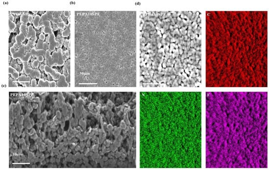
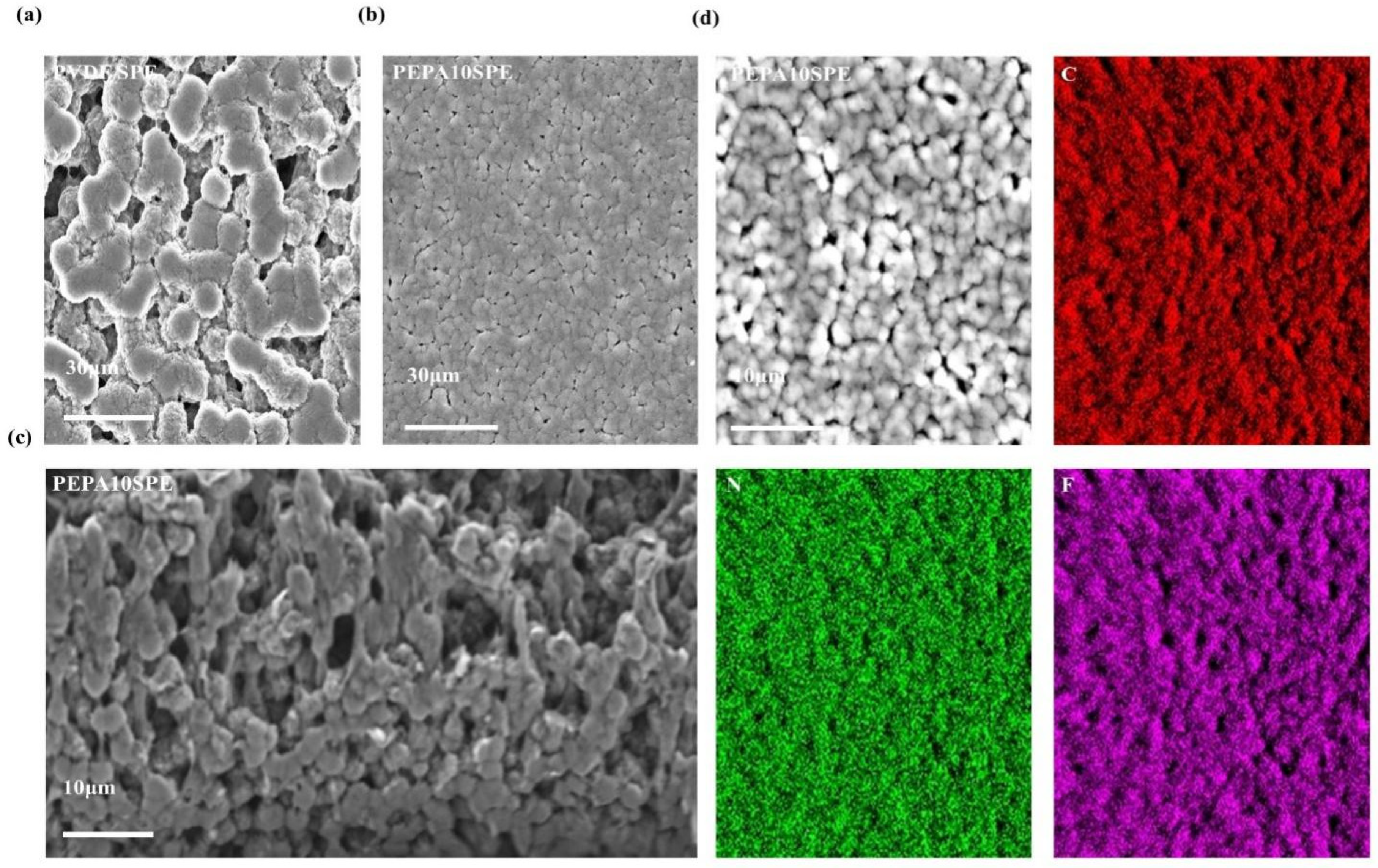
Figure 3 shows the SEM images and EDS elemental mapping results of PVDFSPE and PEPA10SPE. Figure 3a shows the surface morphology of PVDFSPE, where the scale bar corresponds to 30 μm, revealing a distinct particle-stacking structure on the membrane surface. Interparticle pores and gaps are observed, indicating a relatively loose surface structure. Figure 3b shows the surface morphology of PEPA10SPE, where the scale bar corresponds to 30 μm. Compared with PVDFSPE, PEPA10SPE exhibits a more uniform surface morphology, flatter particle interfaces, fewer pores, and improved membrane continuity.
Figure 3.
(a) SEM image of PVDFSPE; (b) surface SEM image of PEPA10SPE; (c) cross-sectional SEM image of PEPA10SPE; (d) EDS elemental mapping images of PEPA10SPE (C, N, and F).
Figure 3c presents the cross-sectional SEM image of PEPA10SPE, showing a relatively compact internal structure without obvious through-thickness voids. The incorporation of PEPA contributes to increasing the overall compactness of the membrane. Figure 3d shows the EDS elemental mapping of PEPA10SPE, where C, N, and F elements are uniformly distributed throughout the membrane.
The C element originates from the polymer backbone, the F element from both the PVDF chains and the TFSI− anion, and the N element predominantly from the TFSI− anion of LiTFSI, indicating that the lithium salt is homogeneously distributed within the membrane. No obvious aggregation or localized enrichment of these elements was observed, indicating the uniform dispersion of PEPA within the PVDF matrix. The consistency between the morphological observations and elemental distribution results indicates that PEPA incorporation optimizes the membrane microstructure, which may facilitate the formation of more continuous and stable ion transport pathways.
To more intuitively present the mechanical properties of different samples, 180° peel tests were conducted on PVDFSP, PEPA5SPE, PEPA10SPE, and PEPA15SPE, yielding average adhesion forces of 0.24 N, 0.55 N, 0.62 N, and 0.74 N for PVDFSP, PEPA5SPE, PEPA10SPE, and PEPA15SPE, respectively. This demonstrates that the addition of PEPA significantly enhances the mechanical properties of the solid-state electrolyte dry film.
3.2. Electrochemical Characterization
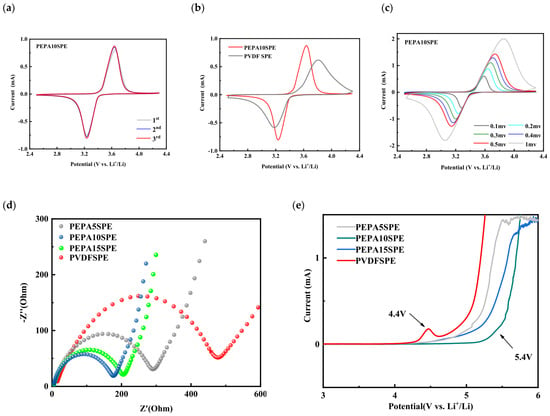
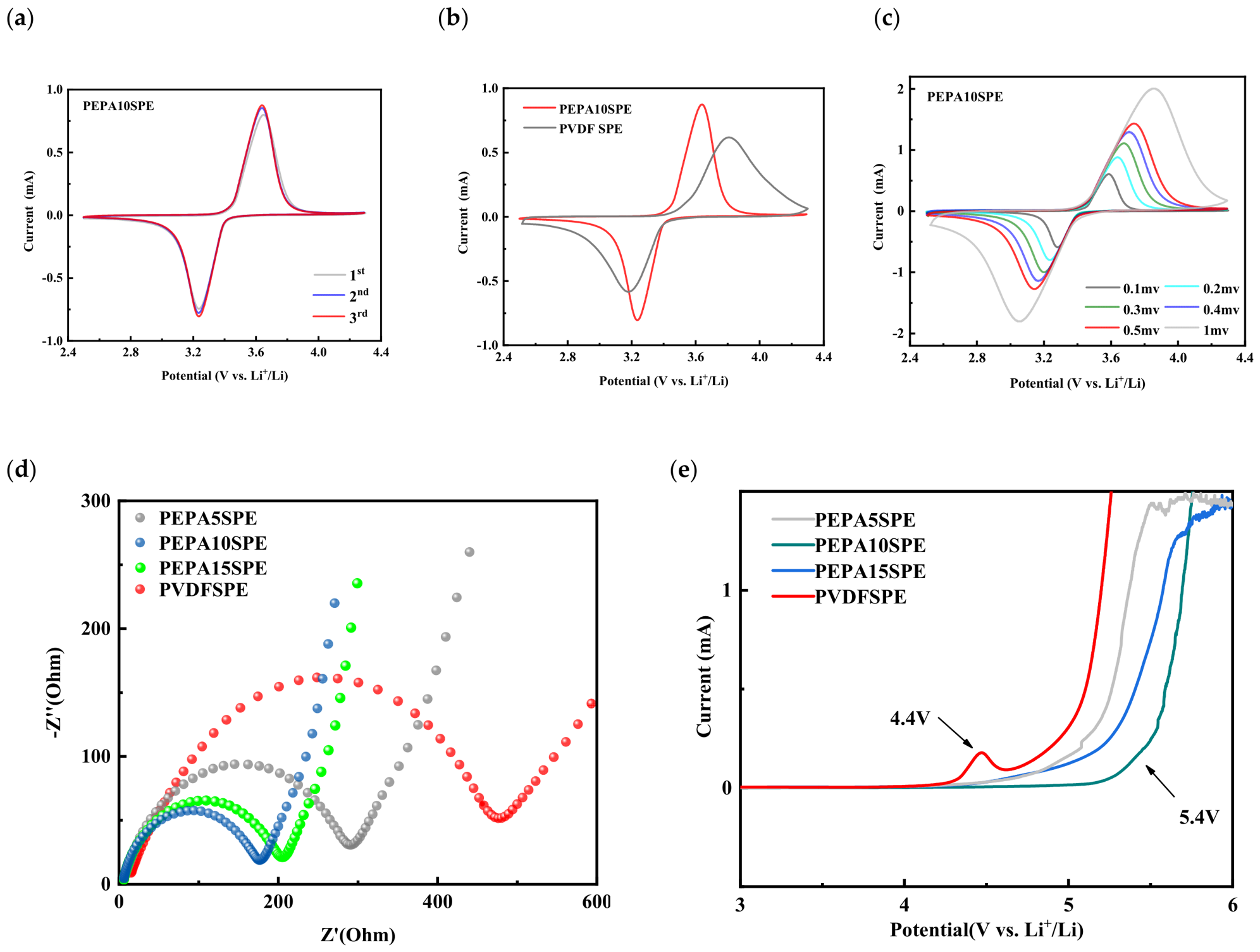
Figure 4a–c show the cyclic voltammetry (CV) curves of Li|SPE|LFP cells assembled with different electrolyte membranes. Figure 4a shows the CV curves of PEPA10SPE over three consecutive cycles at a scan rate of 0.1 mV s−1. The three curves highly overlapped, and the oxidation and reduction peak positions remain nearly unchanged with only slight variations in peak current, indicating a stable electrode/electrolyte interface and good electrochemical reversibility during repeated cycling.
Figure 4.
(a) CV curves of PEPA10SPE for the first three cycles; (b) comparison of CV curves between PVDFSPE and PEPA10SPE; (c) CV curves of PEPA10SPE at different scan rates, (d) EIS curves of PVDFSPE and different ratios of PEPA SPE; (e) LSV curves of different ratios PEPA SPE and PVDFSPE at 10 mV s−1 scan rate.
Figure 4b compares the CV curves of PEPA10SPE and PVDFSPE at the same scan rate. Both samples exhibit a pair of distinct redox peaks at approximately 3.2 and 3.6 V, corresponding to the reversible phase transition between LFP and FePO4. Compared with PVDFSPE, PEPA10SPE exhibits sharper redox peaks, higher peak currents, and a smaller peak-to-peak separation. In contrast, PVDFSPE shows broader peaks with larger separation, indicating more pronounced polarization and relatively sluggish interfacial kinetics. This suggests that PEPA incorporation effectively reduces polarization and facilitates electrode reaction kinetics.
Figure 4c shows the CV curves of PEPA10SPE recorded at different scan rates. As the scan rate increases from 0.1 to 1 mV s−1, the redox peak currents gradually increase with slight peak shifts, attributable to the combined effects of electrode kinetics and ion diffusion. The peak shapes remain well-defined without significant distortion, suggesting stable electrochemical response over a wide range of scan rates.
Figure 4e presents the linear sweep voltammetry (LSV) curves of the different electrolyte membranes. PVDFSPE exhibits a noticeable oxidation current increase at approximately 4.4 V, indicating oxidative decomposition near this potential and a relatively narrow electrochemical stability window. In contrast, PEPA5SPE, PEPA10SPE, and PEPA15SPE maintain low oxidation currents below 5.0 V, with the rapid current rise postponed to approximately 5.3–5.4 V, indicating broadened electrochemical stability windows by PEPA incorporation. Among them, PEPA10SPE shows the most gradual current increase and the highest oxidation onset potential. Further increasing PEPA to 15% retains a wider window than PVDFSPE but alters the current evolution in the high-voltage region. This suggests that the PEPA-induced cross-linked structure enhances polymer chain stability and suppresses structural degradation under high-voltage conditions, with an optimal content at 10% [23,24].
Finally, Figure 4d shows the electrochemical impedance spectroscopy (EIS) Nyquist plots of Li|SPE|LFP cells to further elucidate interfacial charge-transfer and ion-transport kinetics. All cells exhibit a high-frequency intercept, a characteristic arc in the intermediate-frequency region, and an inclined line in the low-frequency region. PVDFSPE exhibits the highest overall impedance. Upon PEPA incorporation, the overall cell impedance decreases markedly, with PEPA10SPE showing the lowest impedance among all samples. PEPA5SPE and PEPA15SPE also show lower impedance than PVDFSPE, although the reduction is less pronounced than for PEPA10SPE. Consistent with the superior charge–discharge reversibility, rate behavior, and CV kinetics described above, this impedance evolution can be attributed to the increased amorphous phase fraction and improved electrode/electrolyte interfacial contact induced by the cross-linked PEPA component, which together facilitate Li+ transport within the electrolyte and across the interfaces.
3.3. Ionic Conductivity and Li+ Transference Number
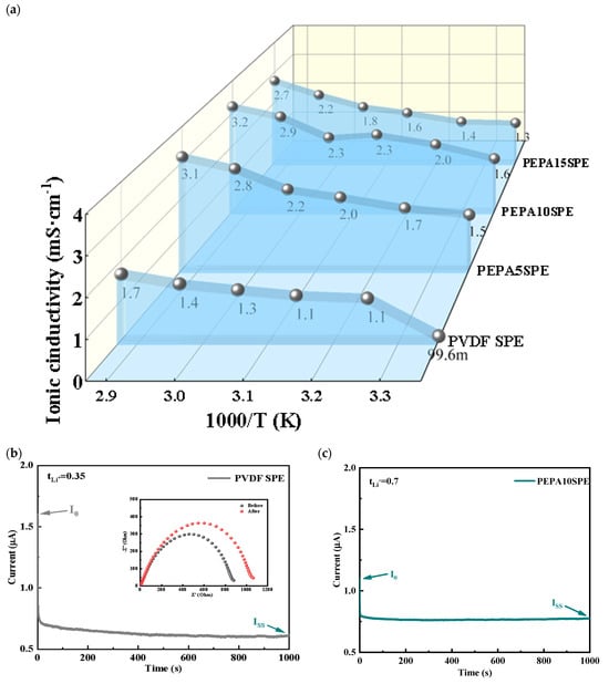
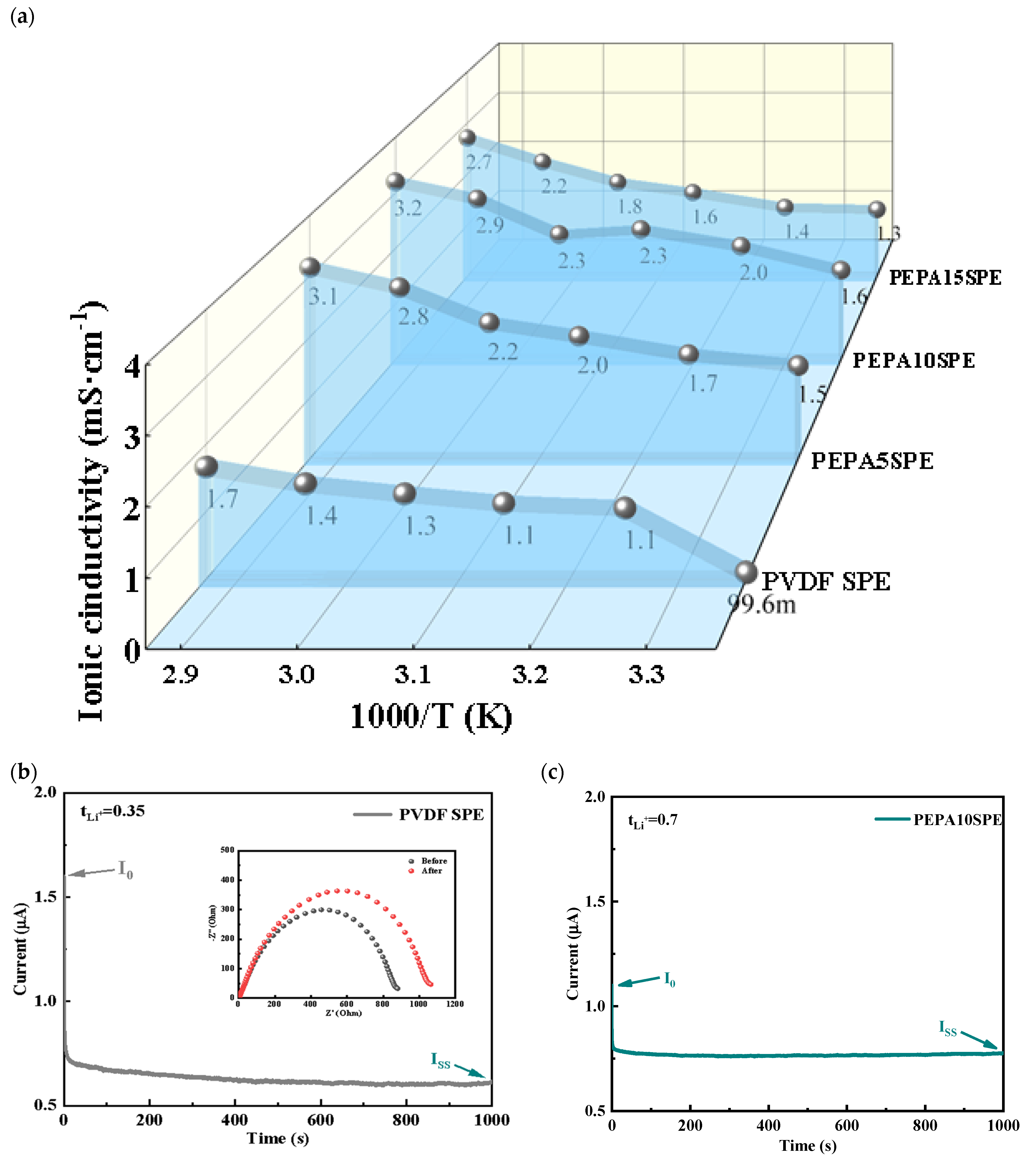
Figure 5a shows the variation in ionic conductivity of different electrolyte membranes over the temperature range of 25–75 °C. As the temperature increases, the ionic conductivity of each sample exhibits a continuous increase, indicating that ion transport is strongly associated with the thermally activated motion of polymer segments. Increasing the temperature promotes local segmental relaxation and Li+ coordination/decoordination processes, thereby facilitating Li+ migration within the polymer matrix.
Figure 5.
(a) Ionic conductivity versus temperature curves for PVDFSPE and different ratios of PEPA SPE; (b) Li|PVDFSPE|Li and (c) Li|PEPA10SPE|Li cells 1000 s timing current measurements.
PVDFSPE exhibits the lowest ionic conductivity across the entire temperature range, with values of approximately 1.0 × 10⁻³ S cm−1 at 25 °C and 1.7 × 10⁻³ S cm−1 at 75 °C. After incorporating PP, the ionic conductivity significantly increases, with PEPA10SPE exhibiting the highest conductivity across the entire temperature range, reaching approximately 1.5 × 10⁻³ S cm−1 at 25 °C and 3.1 × 10⁻³ S cm−1 at 75 °C.
Although the ionic conductivity of PEPA5SPE and PEPA15SPE is improved compared with that of PVDFSPE, both remain lower than that of PEPA10SPE, indicating the existence of an optimal PEPA content range. The introduction of an appropriate amount of oxygen-containing functional groups by PEPA provides additional Li+ coordination sites, while the cross-linked network improves membrane continuity and interfacial contact, thereby facilitating the formation of continuous ion-conduction pathways. When the PEPA content is insufficient, the construction of ion-conduction pathways is incomplete; however, excessive PEPA incorporation may induce stronger chain constraints or heterogeneous local structures, thereby limiting the enhancement of ionic conductivity.
Figure 5b,c present the DC polarization test results of Li|SPE|Li symmetric cells assembled with different electrolyte membranes. Figure 5b shows the polarization curve of PVDFSPE. Upon applying a polarization voltage of 10 mV, the polarization current rapidly decreases and gradually reaches a steady state. The calculated lithium-ion transference number (tLi+) is approximately 0.35.
Figure 5c shows the DC polarization results of PEPA10SPE. Under the same conditions, PEPA10SPE exhibits a higher steady-state current, while the interfacial resistance shows only minor changes before and after polarization. The calculated tLi+ value is 0.70, which is significantly higher than that of PVDFSPE. The increased Li+ transference number indicates a higher contribution of Li+ to the total ionic current, thereby suppressing anion migration to some extent. This improvement can be attributed to the cross-linked structure and oxygen-containing coordination sites introduced by PP, which regulate ion transport behavior and enhance the Li+ transference number.
According to Figure 2e, this phenomenon is attributed to the disruption of the original crystalline regions of PVDF caused by the incorporation of PEPA. This structural transformation benefits ionic conduction in two ways. First, the enlarged amorphous fraction and expanded chain spacing create greater free volume, which facilitates Li+ motion and opens continuous Li+ migration channels. Second, the ether oxygen atoms on PEG segments and the carboxyl groups on PAA can coordinate Li+ ions, decoupling them from the lithium salt and providing hopping sites along the crosslinked network. The combination of suppressed crystallinity, expanded interchain distance, and lithium-coordinating crosslinks therefore accounts for the enhanced room-temperature ionic conductivity of the PEPA-modified membrane.
3.4. Cycling and Rate Performance
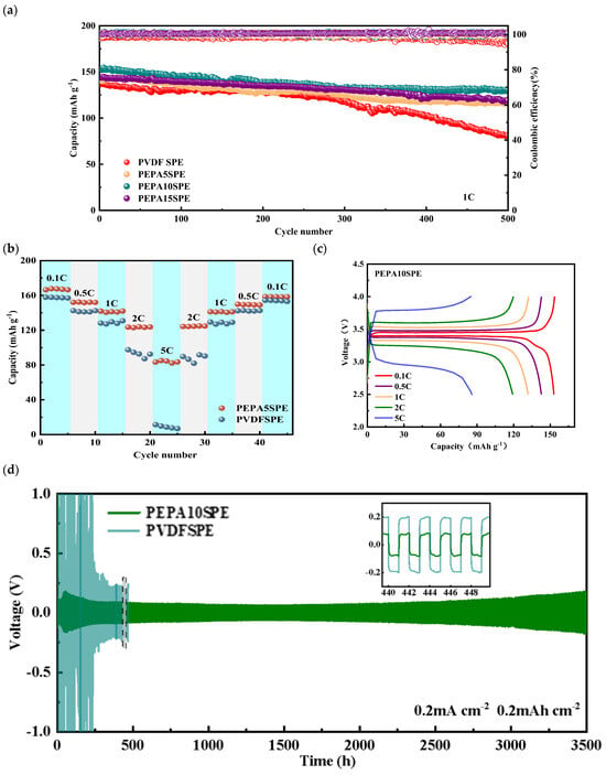
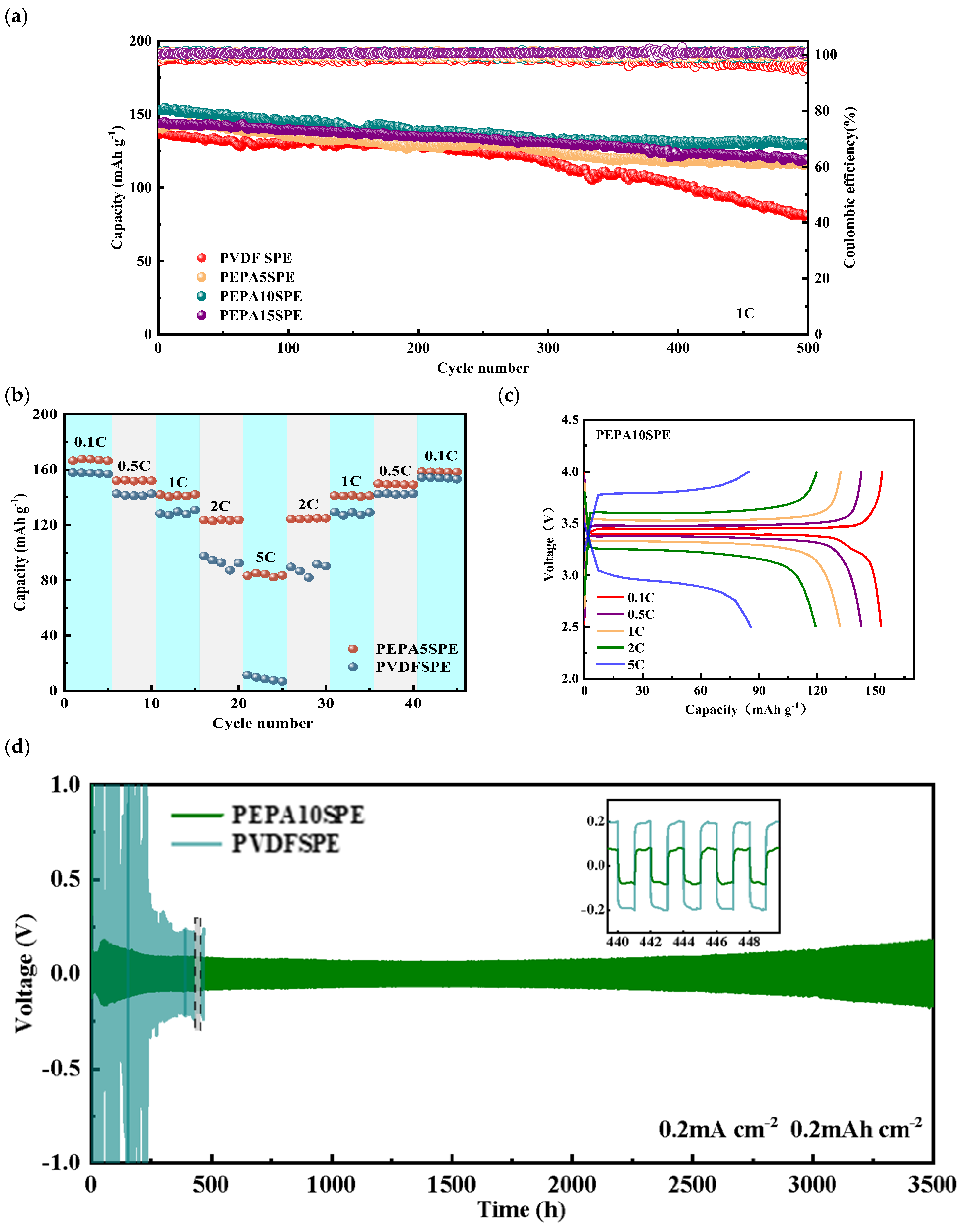
Figure 6a shows the cycling performance and Coulombic efficiency variations of Li|SPE|LFP batteries assembled with different electrolyte membranes at a 1C rate. PVDFSPE maintains an initial discharge specific capacity of approximately 135 mAh g−1 during the early cycling period. As cycling proceeds, capacity fading gradually becomes more pronounced, with a significant decline observed after approximately 300 cycles. After 500 cycles, the discharge capacity decreases to approximately 80 mAh g−1, indicating poor capacity retention. This behavior reflects insufficient interfacial stability and sustained ion transport capability during long-term cycling.
Figure 6.
(a) Cycling performance of LiFePO4|Li cells with PVDFSPE and different ratios of PEPA SPE at 1C; (b) rate performance of LiFePO4|Li cells with PVDFSPE and different ratios of PEPA SPE; (c) charge/discharge voltage curves of LiFePO4|PEPA10SPE|Li; (d) long cycle performance of Li|PVDFSPE|Li and Li|PEPA10SPE|Li symmetric cells.
The capacity retention of the PEPA-modified system is significantly improved, with PEPA10SPE exhibiting the best cycling performance and an initial discharge specific capacity of approximately 150 mAh g−1. During long-term cycling, PEPA10SPE exhibits slow capacity fading and maintains approximately 130 mAh g−1 after 500 cycles, corresponding to a capacity retention of nearly 85%, demonstrating enhanced cycling stability.
PEPA5SPE and PEPA15SPE also exhibit improved cycling performance compared with PVDFSPE but remain slightly inferior to PEPA10SPE in terms of capacity retention and capacity fading rate. These results indicate that an optimal PEPA content range exists, and moderate PEPA incorporation is more beneficial for enhancing electrochemical performance. The Coulombic efficiency of each sample remains close to 100% throughout the cycling process with minimal fluctuations, reflecting stable electrode/electrolyte interfaces and suppressed parasitic reactions. The fluctuation in Coulombic efficiency of the PEPA-based system is smaller, suggesting improved interfacial stability and reduced parasitic reactions.
Based on the aforementioned EIS, conductivity, and Li+ transference number results, the advantages of PEPA10SPE can be attributed to two aspects. First, the cross-linked network and oxygen-containing functional groups provide continuous Li+ coordination and transport pathways while reducing interfacial impedance, enabling the battery to maintain low polarization during cycling. Second, improved interfacial contact facilitates the formation of a more stable SEI layer, thereby mitigating capacity degradation caused by interfacial deterioration during cycling. Therefore, PEPA10SPE achieves an optimal balance between high-capacity retention and long-term cycling stability.
Figure 6b shows the rate performance of PP5%, PP10%, PP15%, and pristine PVDFSPE under different C-rate conditions. As the C-rate increased from 0.1C to 5C, the discharge specific capacity of each sample decreased to different extents. In contrast, the PEPA-modified systems exhibit overall improved rate performance. PEPA10SPE maintains the highest discharge capacity at all C-rates, with capacities of approximately 165 mAh g−1 at 0.1C, 135 mAh g−1 at 1C, and 80 mAh g−1 at 5C, demonstrating excellent high-rate capability. PEPA15SPE exhibits the second-highest capacity, with approximately 160 mAh g−1 at 0.1C and 70 mAh g−1 at 5C. PEPA5SPE exhibits relatively lower capacity, decreasing to approximately 60 mAh g−1 at 5C. Pristine PVDFSPE exhibits the most severe capacity fading during the increase in C-rate, retaining only approximately 50 mAh g−1 at 5C, indicating limited ionic transport capability and interfacial stability.
After the C-rate was reduced from 5C back to 0.1C, the capacity of each PEPA-modified system was largely recovered to its initial value. PEPA10SPE exhibited the highest recovery, indicating superior structural stability and electrochemical reversibility. The limited capacity recovery of PVDFSPE further reflects its insufficient structural stability and interfacial adaptability during high-rate cycling. Overall, a moderate degree of cross-linking (such as PP10%) enhances structural stability while maintaining continuous ion-transport pathways, thereby achieving optimal rate performance. This indicates that the construction of organic cross-linked networks plays a significant role in enhancing the rate performance of PVDF-based solid polymer electrolytes.
3.5. Post-Mortem Analysis of Li|Li Symmetrical Cells
Figure 6c shows the charge–discharge curves of PEPA10SPE at different C-rates. As the C-rate increases, the voltage polarization gradually increases, while the overall voltage profiles remain well-defined. This indicates that the system can maintain relatively stable electrochemical reactions under higher current densities. The reduced voltage polarization and more complete charge–discharge profiles indicate that PEPA incorporation improves ionic transport continuity and electrode/electrolyte interfacial contact, enabling stable electrochemical responses under high-rate conditions.
Figure 6d shows the long-term cycling performance of Li|SPE|Li symmetric cells with different electrolytes at a current density of 0.2 mA cm−2. PVDFSPE exhibits significant voltage fluctuations during the initial cycling stage, with the polarization voltage gradually increasing over time and showing pronounced instability over several hundred hours. The interfacial impedance gradually increases, accompanied by inhomogeneous Li plating/stripping behavior. PEPA10SPE exhibits a more stable voltage response throughout the entire cycling process, with the polarization voltage remaining within a relatively low and stable range.
The cycling duration exceeds 3000 h without sudden voltage instability, demonstrating excellent interfacial stability and reversible Li plating/stripping behavior. The enlarged image shows that the voltage profiles during the Li plating/stripping process exhibit high symmetry and good repeatability, indicating relatively uniform Li deposition morphology.
This result indicates that PEPA incorporation improves the interfacial contact between the electrolyte membrane and lithium metal, thereby suppressing the increase in interfacial impedance. Meanwhile, the cross-linked structure enhances the mechanical robustness of the electrolyte membrane. A stable interface suppresses local current concentration and dendrite growth, thereby significantly extending the stable cycling lifetime of symmetric cells.
To further highlight the novelty and advantages of the as-prepared electrolyte, Table 3 compares the ionic conductivity, Li+ transference number, and cycling stability of PEPA10SPE with previously reported PVDF-based polymer electrolytes. Benefiting from the amorphous PEPA component that disrupts the crystalline packing of PVDF, PEPA10SPE delivers a competitive room-temperature ionic conductivity and cycling performance without introducing any inorganic ceramic fillers.
Table 3.
Comparison of PEPA10SPE with previously reported PVDF-based polymer electrolytes.
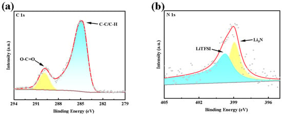
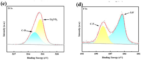
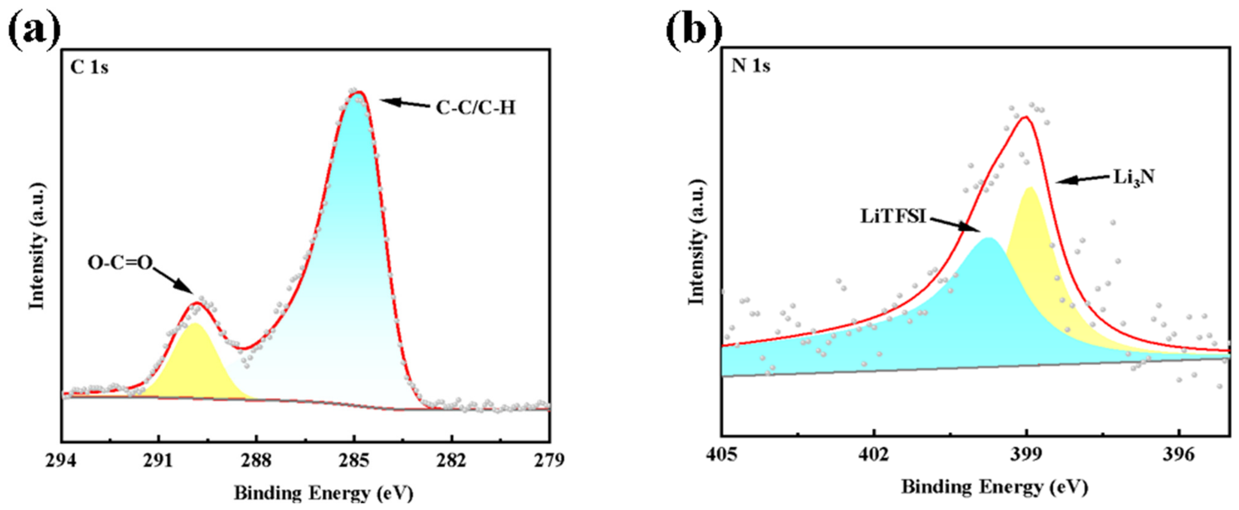
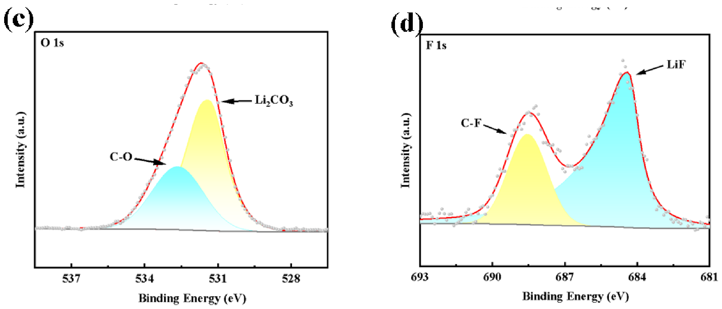
To further investigate the interfacial stability between the PEPA-modified solid polymer electrolyte and lithium metal anode, XPS analysis was performed to characterize the composition of the SEI layer formed on the lithium metal surface after 3500 h of cycling at 0.2 mA cm−2. As shown in Figure 7, the C 1s spectrum exhibits a dominant peak at 284.8 eV, corresponding to C–C/C–H bonds originating mainly from the polymer backbone and organic components in the SEI. The O–C=O peak observed at 289.5 eV indicates the presence of carbonate/carboxylate species at the interface, which is consistent with carbonate products generated from electrolyte decomposition during cycling.
Figure 7.
XPS spectra of (a) C 1s, (b) N 1s, (c) O 1s and (d) F 1s of Li metal anode after Li|PEPA10SPE|Li cycling.
The N 1s spectrum was deconvoluted into two components centred at 399.5–400 eV and 398–399 eV. The component at the higher binding energy is assigned to the imide nitrogen of the –SO2–N–SO2– moiety, indicating the presence of residual LiTFSI or its decomposition fragments retained within the SEI, whereas the component at the lower binding energy is attributed to Li3N formed through reductive decomposition of the TFSI− anion, confirming the formation of an inorganic nitrogen-containing species within the SEI after cycling.
The O 1s spectrum was deconvoluted into two components located at 531 eV and 532–533 eV, corresponding to Li2CO3 and C–O species, respectively, indicating that the SEI consists of both inorganic carbonates and organic oxygen-containing species.
The F 1s spectrum was deconvoluted into a LiF component at 684–685 eV and a C–F component at 688–689 eV; the former originates from the decomposition of the lithium salt, whereas the latter is associated with the PVDF backbone.
LiF, as an electronically insulating component, can prevent electron penetration through the SEI layer, suppress interfacial parasitic reactions, and facilitate Li+ transport across the SPE interface, thereby enhancing interfacial stability.
The surface of the uncycled lithium foil is not bare metallic lithium but is naturally covered by a nanoscale passivation layer formed through reactions with ambient O2, H2O, and CO2 during production and storage [30,31,32].
Overall, a composite SEI layer consisting of inorganic species, such as LiF, Li2CO3, and Li3N, and organic carbonate species is formed on the lithium metal anode surface after cycling. This indicates that PEPA-modified electrolytes can construct a relatively stable interfacial composition under long-term cycling conditions, providing a foundation for maintaining battery performance during extended cycling.
4. Conclusions
Using poly(vinylidene fluoride)-based solid polymer electrolyte (PVDFSPE) as the matrix, a cross-linking product prepared from PAA and PEG via the EDC/NHS coupling system was incorporated, and composite solid polymer electrolyte membranes with different PEPA contents were fabricated. Their structural characteristics, thermal stability, and electrochemical performance were systematically investigated. Structural characterization results indicate that the electrolyte membrane retains the characteristic PVDF framework after PEPA incorporation, while characteristic C=O and C–O–C absorption peaks associated with PEPA are observed in the FTIR spectra, confirming the successful introduction of oxygen-containing functional groups. XRD results reveal that PEPA incorporation broadens the diffraction peaks and decreases their intensity, indicating reduced crystallinity and an increased amorphous phase fraction.
Regarding ionic transport, the ionic conductivity increases with temperature. PEPA10SPE exhibits an ionic conductivity of approximately 1.5 × 10⁻³ S cm−1 at 25 °C and reaches approximately 3.1 × 10⁻³ S cm−1 at 75 °C, which is significantly higher than that of PVDFSPE. Meanwhile, DC polarization measurements demonstrate that PEPA modification increases the Li+ transference number, indicating a higher contribution of Li+ to the total ionic current. Li|SPE|Li symmetric cell testing demonstrates that the PEPA-modified electrolyte enables stable cycling for 3500 h at 0.2 mA cm−2, with stable voltage profiles and suppressed interfacial impedance growth. After 500 cycles at a 1C rate, PEPA10SPE maintains a discharge specific capacity of approximately 130 mAh g−1, corresponding to a capacity retention of nearly 85%. Overall, the incorporation of cross-linking product PEPA enables synergistic regulation of the structural characteristics and interfacial behavior of poly(vinylidene fluoride)-based solid polymer electrolytes.
Author Contributions
Conceptualization, J.W. and H.P.; validation, J.W., H.P. and Z.S.; formal analysis, J.W. and Z.S.; writing—original draft preparation, J.W., H.P. and Z.S.; investigation, H.P., Z.S., L.S., M.Z., T.L. and Y.W.; data curation, Z.S., L.S., M.Z. and Y.W.; writing—review and editing, J.W.; supervision, J.W. and M.T.; project administration, J.W.; funding acquisition, J.W. and M.T. All authors have read and agreed to the published version of the manuscript.
Funding
This work was Funded by the Leading (Key) Projects of Fujian Province, China (No. 2022Y0006), key technological innovation and industrialization projects of the Department of Industry and Information Technology of Fujian Province (Project numbers: 2022G002, 2023G018, 2024G004) and Innovative Training Program for College Students of Fujian Normal University.
Data Availability Statement
The original contributions presented in this study are included in the article. Further inquiries can be directed to the corresponding author.
Conflicts of Interest
The authors declare no conflicts of interest.
References
- Tang, W.; Feng, L.; Wei, X.; Lai, G.; Chen, H.; Li, Z.; Huang, X.; Wu, S.; Lin, Z. Three-dimensional crosslinked PAA-TA hybrid binders for long-cycle-life SiOx anodes in lithium-ion batteries. ACS Appl. Mater. Interfaces 2022, 14, 56910–56918. [Google Scholar] [CrossRef] [Scilit] [PubMed]
- Motoyama, M.; Hirota, M.; Yamamoto, T.; Iriyama, Y. Temperature effects on Li nucleation at Cu/LiPON interfaces. ACS Appl. Mater. Interfaces 2020, 12, 38045–38053. [Google Scholar] [CrossRef] [Scilit] [PubMed]
- Zhao, L.; Sun, Z.; Zhang, H.; Li, Y.; Mo, Y.; Yu, F.; Chen, Y. An environment-friendly crosslinked binder endowing LiFePO4 electrode with structural integrity and long cycle life performance. RSC Adv. 2020, 10, 29362–29372. [Google Scholar] [CrossRef] [Scilit] [PubMed]
- Wu, S.; Wang, C.; Li, S.; Lin, L.; Tong, Q.; Zhu, M.; Weng, J. Coconstruction of supramolecular lithium-conducting cross-linked networks based on PVDF and triblock polymer nanomicrosphere solid-state polymer electrolytes for lithium-metal batteries. ACS Appl. Mater. Interfaces 2024, 16, 28482–28492. [Google Scholar] [CrossRef] [Scilit] [PubMed]
- Inaoka, T.; Asakura, T.; Otoyama, M.; Motohashi, K.; Sakuda, A.; Tatsumisago, M.; Hayashi, A. Tin interlayer at the Li/Li3PS4 interface for improved Li stripping/plating performance. J. Phys. Chem. C 2023, 127, 10453–10458. [Google Scholar] [CrossRef] [Scilit]
- Roh, Y.; Kim, Y.-J.; Lee, J.; Baek, J.; Lee, J.-H.; Yoon, J.K.; Hah, H.J.; Kim, J.Y.; Kim, H.-T. Sustainable formation of sulfur-enriched solid electrolyte interface on a Li metal electrode by sulfur chain-containing polymer electrolyte interfacial layers. ACS Appl. Energy Mater. 2020, 3, 10070–10079. [Google Scholar] [CrossRef] [Scilit]
- Liu, F.; Cai, T.; Zhu, Y.; Bai, T.; Nie, M.; Gan, W.; Li, D.; Ci, L.; Yuan, Q. Li-Ag alloy anode with interfacial silver layer for all-solid-state lithium metal batteries utilizing Li3InCl6 halide solid electrolyte. J. Power Sources 2025, 647, 237357. [Google Scholar] [CrossRef] [Scilit]
- Chen, Z.; Zhang, Q.; Tang, W.; Li, D.; Ding, J.; Huang, C.; Yang, Z.; Zhang, W.; Wu, G.; Chen, H. Ultrahigh capacity retention of a Li2ZrO3-coated Ni-rich LiNi0.8Co0.1Mn0.1O2 cathode material through covalent interfacial engineering. ACS Appl. Energy Mater. 2021, 4, 13785–13795. [Google Scholar] [CrossRef] [Scilit]
- Gao, Y.; Liu, W.; Cui, Y.; Zhang, H.; Li, X.; Dong, H.; Yue, H.; Yang, S.; Yin, Y. Silicic acid-assisted interface engineering strategy to improve the performance of Li1.2Mn0.6Ni0.2O2 cathode material. ACS Appl. Energy Mater. 2022, 5, 12109–12119. [Google Scholar] [CrossRef] [Scilit]
- Qiu, J.; Yang, L.; Sun, G.; Yu, X.; Li, H.; Chen, L. A stabilized PEO-based solid electrolyte via a facile interfacial engineering method for a high voltage solid-state lithium metal battery. Chem. Commun. 2020, 56, 5633–5636. [Google Scholar] [CrossRef] [Scilit] [PubMed]
- Cheng, Q.; Wang, F.; Yu, Y.; Wang, C.; Shao, Z.; Peng, B.; Guo, Y. 3D interconnected MOF-derived asymmetric bilayer solid-state electrolyte for enabling homogeneous Li deposition of all-solid-state lithium metal batteries. J. Solid State Electrochem. 2024, 28, 2631–2642. [Google Scholar] [CrossRef] [Scilit]
- Peng, Q.; Chen, Y.; Gong, J.; Xu, H.; Wen, T.; Liu, M.; Zhao, S.; Han, Y.; Li, D.; Wang, S.; et al. Cationic chain-anchored monolayer enables wide-temperature composite polymer electrolytes for lithium-metal batteries. Nat. Commun. 2026, 17, 11305. [Google Scholar] [CrossRef] [Scilit] [PubMed]
- Zhang, Y.; Liu, H.; Liu, F.; Zhang, S.; Zhou, M.; Liao, Y.; Wei, Y.; Dong, W.; Li, T.; Liu, C.; et al. Dual-Anion-Rich Polymer Electrolytes for High-Voltage Solid-State Lithium Metal Batteries. ACS Nano 2025, 19, 3197–3209. [Google Scholar] [CrossRef] [Scilit] [PubMed]
- Li, Y.; Yuan, W.; Hu, Z.; Shen, Y.; Wu, G.; Cong, F.; Fu, X.; Lu, F.; Li, Y.; Liu, P.; et al. Constructing PVDF-Based Polymer Electrolyte for Lithium Metal Batteries by Polymer-Induced Phase Structure Adjustment Strategy. Adv. Funct. Mater. 2025, 35, 2424763. [Google Scholar] [CrossRef] [Scilit]
- Fan, K.; Chen, J.; Wang, B.; Cao, K.; Zhang, C.; Chen, J.; Zhao, Y.; Yuan, J.; Hu, Z.; Wang, L. The synergistic regulation of interface and bulk for high-entropy PVDF-based electrolytes endows ultra-long cycling of solid-state lithium metal batteries. Nano Energy 2025, 147, 111594. [Google Scholar] [CrossRef] [Scilit]
- Luo, S.; Liu, X.; Zhang, X.; Wang, X.; Wang, Z.; Zhang, Y.; Wang, H.; Ma, W.; Zhu, L.; Zhang, X. Nanostructure of the interphase layer between a single Li dendrite and sulfide electrolyte in all-solid-state Li batteries. ACS Energy Lett. 2022, 7, 3064–3071. [Google Scholar] [CrossRef] [Scilit]
- Yang, G.; Bai, X.; Zhang, Y.; Guo, Z.; Zhao, C.; Fan, L.; Zhang, N. A bridge between ceramics electrolyte and interface layer to fast Li+ transfer for low interface impedance solid-state batteries. Adv. Funct. Mater. 2023, 33, 2211387. [Google Scholar] [CrossRef] [Scilit]
- Yang, C.T.; Qi, Y. Maintaining a flat Li surface during the Li stripping process via interface design. Chem. Mater. 2021, 33, 2814–2823. [Google Scholar] [CrossRef] [Scilit]
- Ye, B.; Cai, X.; Wang, D.; Saha, P.; Wang, G. A novel poly(vinyl carbonate-co-butyl acrylate) quasi-solid-state electrolyte as a strong catcher for lithium polysulfide in Li-S batteries. Electrochim. Acta 2020, 332, 135463. [Google Scholar] [CrossRef] [Scilit]
- Chen, B.; Wu, S.; Shi, Z.; Li, S.; Chen, Z.; Li, T.; Tong, Q.; Gao, J.; Tian, M.; Weng, J. Enhanced Li+ transport and uniform deposition in composite solid-state polymer electrolytes based on a dual lithium salt system with 3D ion pathways. J. Electroanal. Chem. 2025, 996, 119331. [Google Scholar] [CrossRef] [Scilit]
- Xie, S.; Yu, S.; Hou, Y.; Dong, F.; Zhang, X.; Zheng, H.; Xie, H.; Wang, Z.; Liu, Y. Ga-polymer dual interfacial layer modified Li metal for high-energy Li metal batteries. J. Energy Storage 2024, 91, 112056. [Google Scholar] [CrossRef] [Scilit]
- Riegger, L.M.; Schlem, R.; Sann, J.; Zeier, W.G.; Janek, J. Lithium-metal anode instability of the superionic halide solid electrolytes and the implications for solid-state batteries. Angew. Chem. Int. Ed. 2021, 60, 6718–6723. [Google Scholar] [CrossRef] [Scilit] [PubMed]
- Yao, H.; Rong, L.; Tan, H.; Han, Y.; Fan, S.; Huang, Z.; Xia, R.; Zhang, Z.; Mei, T. Electrostatic self-assembled aminated dendritic silica/lithium polyacrylate artificial interphase for long-life Li metal anodes. J. Colloid Interface Sci. 2026, 718, 140525. [Google Scholar] [CrossRef] [Scilit] [PubMed]
- Liu, X.; Guo, W.; Wang, M.; Guo, H.; Li, P.; Cao, L.; Zhang, J.; Li, X.; Xia, Q. A molecular precursor pre-anchoring strategy for constructing stable solid electrolyte interphase in carbonate-based lithium metal batteries. Green Chem. 2026, 28, 12321–12333. [Google Scholar] [CrossRef] [Scilit]
- Choi, W.; Sung, G.H.; Yu, W.-R.; Kim, D.W. Gel polymer electrolytes based on crosslinked networks by the introduction of an ionic liquid crosslinker with ethylene oxide arms. ACS Appl. Energy Mater. 2022, 5, 8381–8390. [Google Scholar] [CrossRef] [Scilit]
- He, M.; Fan, Y.; He, N.; Li, Y.; Yan, Y.; Yang, K.; Liu, S.; Zhang, B.; Luo, E.; Chen, W.; et al. Zwitterionic Polymer Electrolytes with Dipole-Rotation-Assisted Ion Conduction for Solid Lithium Metal Batteries. Adv. Mater. 2026, 38, e73925. [Google Scholar] [CrossRef] [Scilit] [PubMed]
- Li, Z.; Wang, T.; Zhong, L.; Xiao, M.; Han, D.; Wang, S.; Zhang, S.; Huang, S.; Meng, Y. Ultrathin thiol-ene crosslinked polymeric electrolyte for solid-state and high-performance lithium metal batteries. Sci. China Mater. 2023, 66, 1332–1340. [Google Scholar] [CrossRef] [Scilit]
- Yang, M.; Liu, B.T.; Gao, G.; Liu, X.L.; Liu, F.Q. Poly(maleic anhydride-co-acrylic acid)/poly(ethylene glycol) hydrogels with pH- and ionic-strength-responses. Chin. J. Polym. Sci. 2010, 28, 951–959. [Google Scholar] [CrossRef] [Scilit]
- Rynkowska, E.; Fatyeyeva, K.; Marais, S.; Kujawa, J.; Kujawski, W. Chemically and Thermally Crosslinked PVA-Based Membranes: Effect on Swelling and Transport Behavior. Polymers 2019, 11, 1799. [Google Scholar] [CrossRef] [Scilit] [PubMed]
- Otto, S.K.; Moryson, Y.; Krauskopf, T.; Peppler, K.; Sann, J.; Janek, J.; Henss, A. In-Depth Characterization of Lithium-Metal Surfaces with XPS and ToF-SIMS: Toward Better Understanding of the Passivation Layer. Chem. Mater. 2021, 33, 859–867. [Google Scholar] [CrossRef] [Scilit]
- Baek, M.; Kim, J.; Jeong, K.; Yang, S.; Kim, H.; Lee, J.; Kim, M.; Kim, K.J.; Choi, J.W. Naked metallic skin for homo-epitaxial deposition in lithium metal batteries. Nat. Commun. 2023, 14, 1296. [Google Scholar] [CrossRef] [Scilit] [PubMed]
- Kamphaus, E.P.; Angarita-Gomez, S.; Qin, X.; Shao, M.; Engelhard, M.; Mueller, K.T.; Murugesan, V.; Balbuena, P.B. Role of Inorganic Surface Layer on Solid Electrolyte Interphase Evolution at Li-Metal Anodes. ACS Appl. Mater. Interfaces 2019, 11, 31467–31476. [Google Scholar] [CrossRef] [Scilit] [PubMed]

Disclaimer/Publisher’s Note: The statements, opinions and data contained in all publications are solely those of the individual author(s) and contributor(s) and not of MDPI and/or the editor(s). MDPI and/or the editor(s) disclaim responsibility for any injury to people or property resulting from any ideas, methods, instructions or products referred to in the content. |
© 2026 by the authors. Licensee MDPI, Basel, Switzerland. This article is an open access article distributed under the terms and conditions of the Creative Commons Attribution (CC BY) license.