


Abstract
This study aimed to evaluate the biomechanical behavior of different implant macrogeometries under immediate and delayed implantation protocols in a single maxillary anterior tooth model using three-dimensional finite element analysis. Six implant models from three different implant systems were analyzed, each including one aggressive and one passive macrogeometric design. In the immediate implantation models, implants were placed within the extraction socket, with the buccal gap filled using a xenograft material, whereas in the delayed implantation models, a fully remodeled healed bone condition was simulated. Stress and strain distributions were evaluated under a 120 N static oblique load representing functional occlusal forces in the anterior maxilla. Under immediate implantation conditions, aggressive designs demonstrated a more homogeneous stress distribution and reduced cervical stress concentration compared with passive designs, while maintaining comparable apical stress levels. Similarly, in delayed implantation models, aggressive macrogeometries exhibited lower stress concentrations in the cervical cortical bone relative to cylindrical designs. Overall, these findings suggest that aggressive implant macrogeometry may favorably balance cervical stress reduction and apical load transfer, supporting peri-implant bone preservation while maintaining primary mechanical anchorage.
1. Introduction
Dental implants are regarded as an effective treatment option with high long-term success rates for meeting both functional and aesthetic needs. They are used to support fixed or removable prostheses in cases of partial or complete edentulism. Recent investigations in the field of oral implantology have increased the predictability of treatment processes, reduced complication rates, and improved overall patient satisfaction.
The timing of implant placement following tooth extraction can be determined based on the clinical condition of the patient and treatment options within different surgical protocols. These protocols are generally classified under four main categories: immediate implantation (implant placement during the same session as extraction), early implantation (implant placement 4–8 weeks after extraction), delayed early implantation (implant placement 8–12 weeks after extraction), and late implantation (implant placement more than 12 weeks after extraction) [1].
Immediate implantation refers to the placement of a dental implant during the same surgical session as tooth extraction. This approach aims to reduce the overall treatment duration and minimize tissue loss by placing the implant directly into the extraction socket [2]. In immediate implantation, the preservation of alveolar bone and soft tissue volume provides successful outcomes both functionally and aesthetically [3]. Thus, patients can achieve functional and aesthetic rehabilitation in a shorter time. Despite the clinical advantages of immediate implantation, it also has some significant disadvantages and clinical risks. One of the main concerns is the difficulty in achieving primary stability of the implant, which largely depends on the morphology of the extraction socket and the available bone volume. An implant placed immediately after tooth extraction is often narrower than the natural structure of the alveolar socket, resulting in the formation of gaps around the implant. This is a common issue in sockets that are wide and located in areas of low bone density, where achieving primary stability is more difficult. If adequate stability cannot be achieved, the osseointegration process may be unsuccessful [4].
Delayed implantation protocol refers to the placement of a dental implant following a healing period of approximately 8–12 weeks after tooth extraction [5]. In the healing phase, the reduction in inflammation within the alveolar socket contributes to the stabilization of the bone prior to implant placement. Additionally, complete recovery of soft tissues allows for more effective soft tissue management, especially in the anterior aesthetic region, resulting in more predictable functional and aesthetic outcomes [1]. However, delayed implantation is often accompanied by significant alveolar bone resorption in the early post-extraction weeks. Araújo and Lindhe demonstrated that bone volume loss in the first 4–8 weeks may lead to narrowing of the implant site and an increased need for grafting procedures [6]. Furthermore, the prolonged treatment timeline can complicate clinical management and negatively impact patient satisfaction.
The timing of implant loading can vary significantly depending on clinical conditions and treatment protocols. Common classifications include delayed (conventional), early, and immediate implant loading. Each approach has its own clinical indications, advantages, and potential limitations. In contemporary implant dentistry, the concept of immediate loading has gained increasing prominence due to increasing patient expectations for reduced treatment durations, supported by advances in clinical technology [7]. This protocol enables the placement of functional and aesthetic prosthetic restorations within a short period following implant insertion, thereby significantly reducing the overall treatment timeline and improving patient-reported outcomes.
Dental implant designs vary depending on the clinical case and intended application. Modern implant systems used in the field of implant dentistry incorporate a range of macro- and micro-design features aimed at enhancing biomechanical stability and optimizing osseointegration. The most widely used implants are screw-shaped devices that anatomically resemble the natural tooth root. At the macroscopic level, implants typically exhibit cylindrical, conical, or hybrid geometries. Cylindrical implants, in particular, promote early osseointegration by increasing the bone-to-implant contact surface area through surface modifications such as sandblasting, acid etching, titanium plasma spraying, or hydroxyapatite coating [8].
Conical (tapered) implants are particularly advantageous in posterior regions or in low-density bone because they provide enhanced primary stability. Hence, they are preferred in immediate and early loading protocols [9]. Moreover, certain hybrid designs currently in use combine a cylindrical body with a conical apical portion, aiming to simultaneously achieve extensive bone contact and high mechanical stability. These advancements reflect the ongoing efforts to optimize the factors influencing implant success, thereby establishing implant design as a key parameter in treatment planning.
However, biomechanical evidence directly comparing different implant macrogeometries under both immediate and delayed placement and loading conditions in the anterior maxilla remains limited. This study analyzed the stress and strain distribution on bone in the anterior maxilla for different implant designs under two clinical scenarios: delayed implantation and loading in healed bone, and immediate implantation with immediate loading in extraction sockets with graft placement, using three-dimensional finite element analysis (3D FEM). The anterior maxilla was selected because of its aesthetic relevance and challenging biomechanical conditions. Immediate and delayed placement protocols were included to reflect commonly used clinical scenarios with distinct biomechanical demands, in which implant macrogeometry is expected to play an important role. To the authors’ knowledge, this is the first finite element study to comparatively evaluate aggressive and passive macrogeometric designs from three contemporary implant systems under immediate and delayed placement conditions using a standardized modeling approach.
2. Materials and Methods
2.1. Model Design
This study was conducted in collaboration between the Faculty of Dentistry, Istanbul University, and Tinus Technologies (Ankara, Türkiye). Two clinical implant placement protocols were evaluated. The first scenario involved delayed implant placement (DIP), representing delayed placement and loading. The second scenario involved immediate implant placement (IIP) and immediate loading. A total of three dental implant brands and six implant designs frequently preferred in the clinic were chosen. For each implant brand, one model featuring an aggressive design and another with a more passive design were selected. In the present study, implants were defined as having an aggressive macrogeometry when characterized by a tapered body design combined with more pronounced thread geometry, aimed at increasing bone compression and primary stability. In contrast, passive macrogeometry referred to implants with a predominantly cylindrical body design and less pronounced threads, intended to provide a more uniform load distribution along the implant surface.
The maxillary bone model used in this study was constructed by reconstructing tomographic data from the Visible Human Project with a slice thickness of 0.33 mm. The Visible Human Project dataset was selected due to its high anatomical resolution and widespread use in biomechanical modeling studies, providing a standardized and anatomically consistent representation of maxillofacial structures. The reconstructed tomography data were transferred in Digital Imaging and Communications in Medicine (DICOM) format into the 3DSlicer software (version 5.4, MIT AI Lab, Cambridge, MA, USA). The computed tomography data in DICOM format were segmented in 3DSlicer according to appropriate Hounsfield unit values (threshold range: 426.50–3193.04). The segmented data were subsequently converted into three-dimensional models through segmentation and exported in .stl format.
The three-dimensional models were imported into Blender software (version 4.3, Blender Foundation, Amsterdam, The Netherlands), where a 2 mm inward offset was applied to the maxillary bone model to create a cortical bone layer. The trabecular bone was subsequently generated using the inner surface of the cortical structure as a reference. The dimensions of the extraction socket of the maxillary central incisor were designed with reference to the data reported in the literature [10]. In the IIP model, a xenograft material was placed in the gap between the extraction socket wall and the implant. The objective was to simulate clinical conditions where grafting was applied to enhance bone volume. The xenograft was placed on the buccal surface of the implant in Blender software. All prepared models were then positioned in the correct spatial coordinates within Blender, and the modeling process was completed.
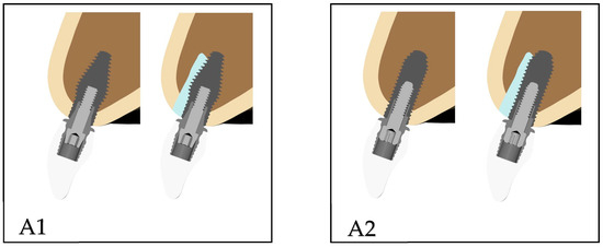
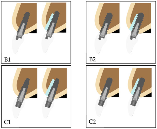
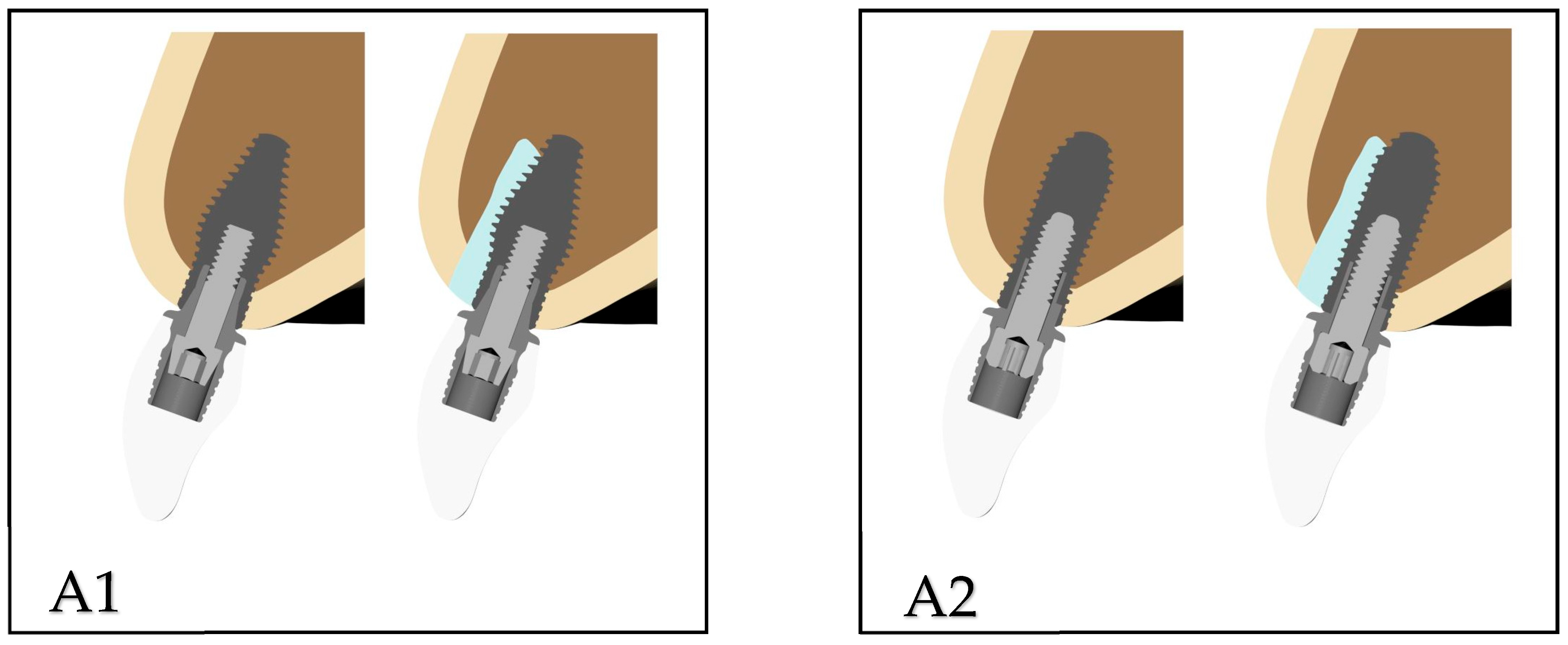
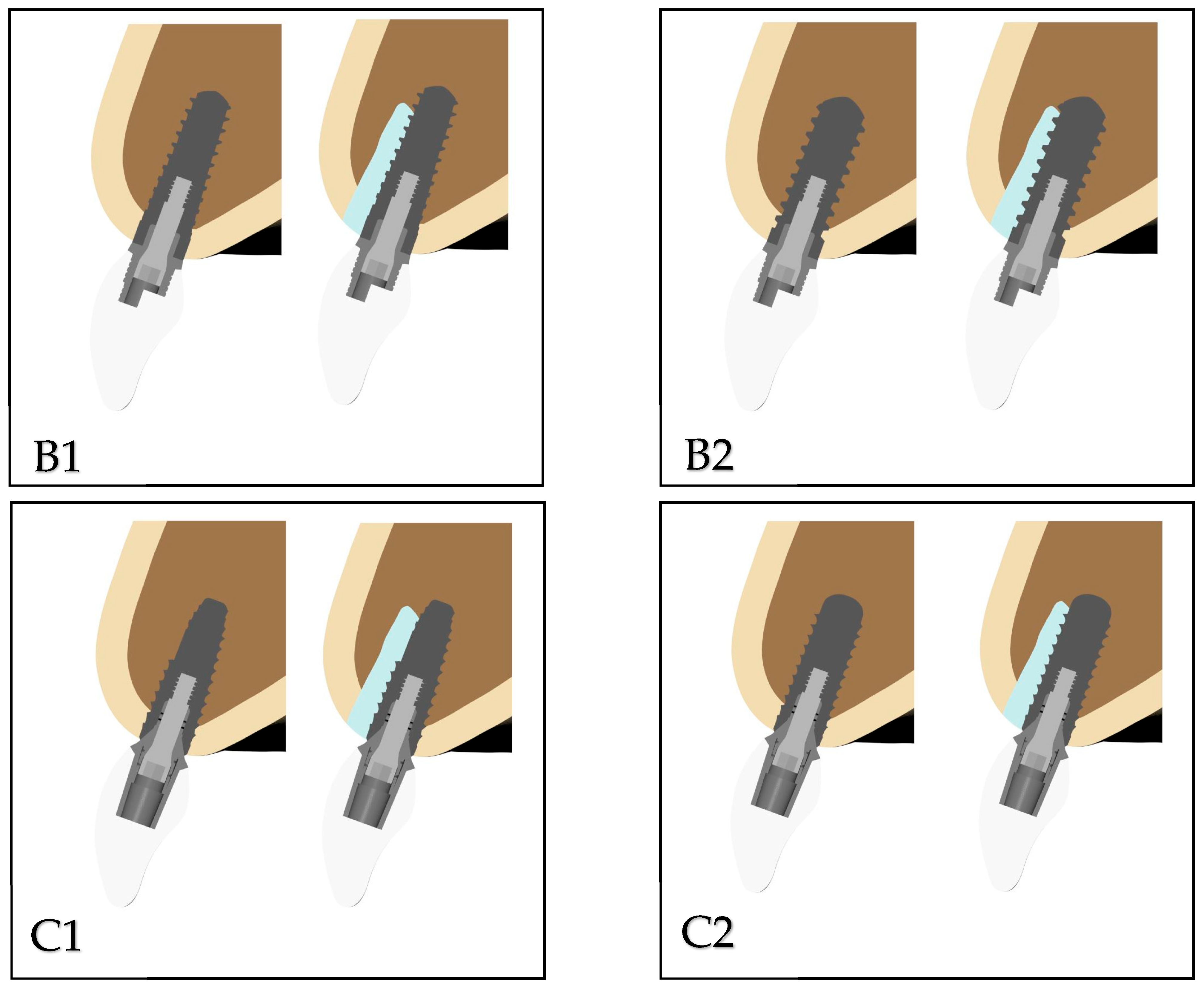
The implants used in the study were as follows: Southern Inverta (Southern Implants; Irene, South Africa) (A1), Southern Cylindrical (Southern Implants) (A2), Thommen Contact (Thommen Medical AG, Grenchen, Switzerland) (B1), Thommen Element (Thommen Medical AG) (B2), Straumann Bone Level Tapered (BLT) (Straumann Holding AG, Basel, Switzerland) (C1), and Straumann Bone Level (BL) (Straumann Holding AG) (C2). For ease of reference, each implant was assigned a specific code name. In this study, the implants and their components, including abutments and screws, were modeled in Blender software based on the dimensions provided in the manufacturers’ catalogs. The implants were selected for the maxillary incisor region such that the average implant height was 10 mm and the width was 3.5 mm based on published data [11]. The Straumann BLT and BL implants comprised a platform with a height of 10 mm and a diameter of 3.3 mm. The Thommen Contact and Element implant systems had a platform with a height of 9.5 mm and a diameter of 3.5 mm. The Southern Inverta and Cylindrical implant designs had a platform with a height of 10 mm and a diameter of 3.5 mm. All implants were placed at a 20° angulation to the sagittal plane. Each implant-supported restoration comprised a zirconia crown to ensure uniformity in prosthetic design. The crown was modeled in Blender software with a length of 9 mm along the long axis of the tooth. The crown length was selected based on the crown-to-implant ratio reported as being associated with the lowest incidence of complications [12]. Delayed and IIPs of each implant are shown in Figure 1.
Figure 1.
Delayed and immediate implant placements of each implant. (A1): Southern Inverta (Southern Implants; Irene, South Africa); (A2): Southern Cylindrical (Southern Implants; Irene, South Africa); (B1): Thommen Contact (Thommen Medical AG, Switzerland); (B2): Thommen Element (Thommen Medical AG, Switzerland); (C1): Straumann BLT (Straumann Holding AG, Switzerland); and (C2): Straumann BL (Straumann Holding AG, Switzerland).
2.2. Material Properties
The bone was modeled as a cancellous core surrounded by a 2 mm thickness of cortical bone in the crestal region. Zirconia was selected as the prosthetic material for all crown restorations. All materials used in the models were considered to be isotropic, homogeneous, and linearly elastic. The elastic properties of materials used in this study were derived from previous studies (Table 1) [9,13,14].
Table 1.
Mechanical properties of materials.
2.3. Interface Conditions
In DIP, the FEM assumed an optimal state of osseointegration. The cortical and trabecular bones were assumed to be perfectly (100%) bonded to the implant. Cortical bone, cancellous bone, and the xenograft material were assumed to be isotropic, homogeneous, and linearly elastic, in line with commonly accepted finite element modeling practices for comparative biomechanical analyses. Continuous, uninterrupted contact was assumed between cortical and trabecular bones, the dental implants and the maxilla, the implants and the abutments, and the abutments and the implant-supported zirconia. In the IIP, a frictional contact with a coefficient of 0.2 was applied at the graft–implant interface. For all other contacting components, a bonded contact definition was implemented. This approach was based on the assumption that the parts moved with complete correlation during motion.
2.4. Element and Nodes
The models were meshed with 10-node brick elements. Considering the model type, the maximum number of elements permitted by the program was selected to obtain realistic results. The number of elements and nodes in delayed implantation of each model was as follows: 755,991 elements and 190,106 nodes in A1 model; 740,188 elements and 187,083 nodes in A2 model; 675,550 elements and 167,460 nodes in B1 model; 679,192 elements and 168,608 nodes in B2 model; 713,840 elements and 178,863 nodes in C1 model; and 719,106 elements and 179,959 nodes in C2 model.
The number of elements and nodes in immediate implantation of each model was as follows: 870,251 elements and 219,473 nodes in A1 model; 862,266 elements and 217,872 nodes in A2 model; 788,144 elements and 196,029 nodes in B1 model; 789,795 elements and 196,652 nodes in B2 model; 821,627 elements and 206,452 nodes in C1 model; and 833,022 elements and 208,771 nodes in C2 model.
2.5. Constraints and Loads
In all models, a single static oblique force of 120 N was applied at an angle of 135° to the long axis of the tooth, which was directed from the palatal aspect toward the labial surface of the crown, as supported by previous findings [15]. The mesh compatibility between structures was established using Altair HyperMesh software (v2024, ALTAIR, Troy, MI, USA) to ensure proper load transfer among the models. The forces were distributed to the surrounding nodes to prevent stress singularities in the loading regions. The models were constrained by fixing all degrees of freedom at the superior and distal nodal points of the bone, thereby restricting motion in all three axes. Under the specified loading and boundary conditions, 6 linear static analyses and 6 nonlinear analyses were performed for the 12 analysis models.
2.6. Finite Element Analysis
The 3D mesh structure was organized and converted into a mathematically appropriate solid mesh. Subsequently, 3D FEM models were constructed, and finite element stress analysis was performed on HP workstations equipped with an Intel Xeon E-2286 processor (2.40 GHz clock speed) and 64 GB of Error-Correcting Code memory.
The maximum principal (tensile) and minimum principal (compressive) stresses were used to display stress in the cortical and cancellous bones and on the apical side of the implant. Figures were obtained from the occlusal and lateral sides of the maxilla to evaluate stress distributions. The points at which strain was measured were selected at equal distances from the implant surface, ensuring that the same reference locations were used for all implant models. The strain values were evaluated according to the bone remodeling thresholds suggested by Frost’s mechanostat theory [16].
3. Results
3.1. Evaluation of Stress Values
3.1.1. Stress Values in IIP
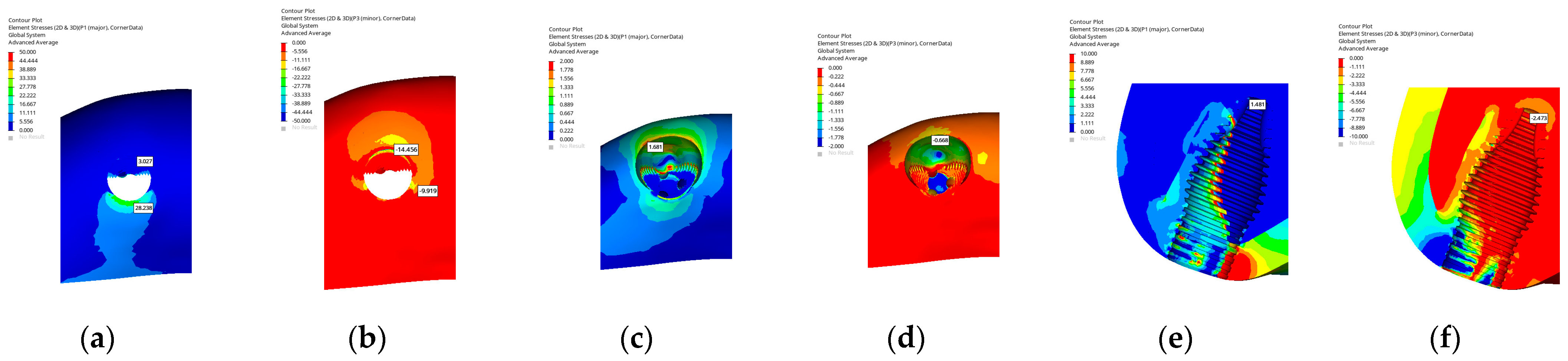
In the A1 implant model featuring a hybrid macrogeometry with a conical apical portion and a cylindrical coronal design, the maximum principal stress in the cortical bone was concentrated on the palatal wall (28.238 MPa), whereas the minimum stress was observed on the buccal side (14.456 MPa) where the grafted region was located. In the cancellous bone, the maximum stress was distributed around the socket walls (1.681 MPa), indicating a wider stress propagation pattern within the peri-socket area, whereas the minimum stress was concentrated in the buccal grafted zone (0.668 MPa). At the apex of the implant, the stress distribution extended along the apical portion of the implant body, demonstrating a balanced load transfer toward the apical region.
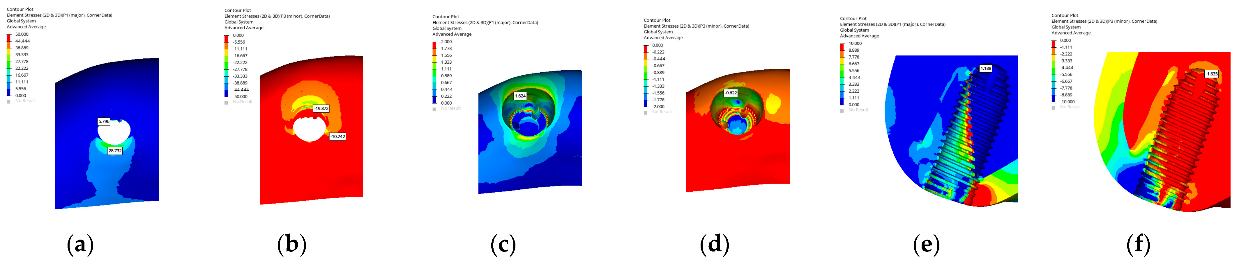
In the A2 implant model with a cylindrical implant macrogeometry, the maximum principal stress in the cortical bone was observed on the palatal wall in the coronal region (28.732 MPa), whereas the minimum stress was located on the buccal side corresponding to the grafted area (19.872 MPa). In the cancellous bone, the maximum stress was distributed around the socket walls and extended slightly toward the mesial region (1.624 MPa), indicating a broader stress propagation pattern, whereas the minimum stress was concentrated within the buccal grafted zone (0.622 MPa). The overall stress distribution demonstrated that the cylindrical geometry resulted in a higher stress concentration on the buccal side, which corresponded to the main loading direction during IIP.
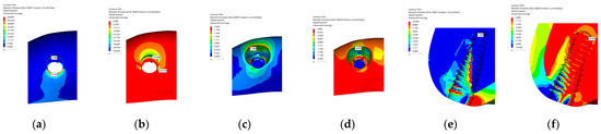
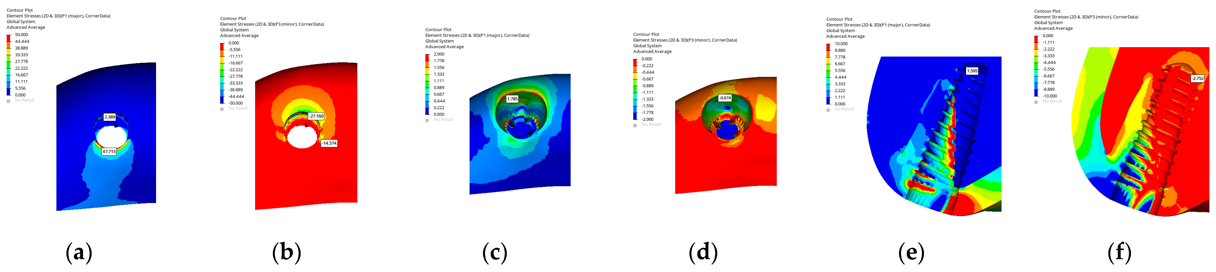
In the B1 implant model featuring a fully conical (tapered) macrogeometry, the maximum principal stress in the cortical bone was concentrated on the palatal wall (47.715 MPa), whereas the minimum stress was observed on the buccal side corresponding to the grafted area (27.160 MPa). In the cancellous bone, the maximum stress was distributed around the socket walls (1.785 MPa), whereas the minimum stress was observed in the buccal and mesial regions (0.674 MPa). Examination from the lateral section showed that the grafted buccal area also received significant load.
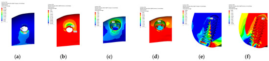
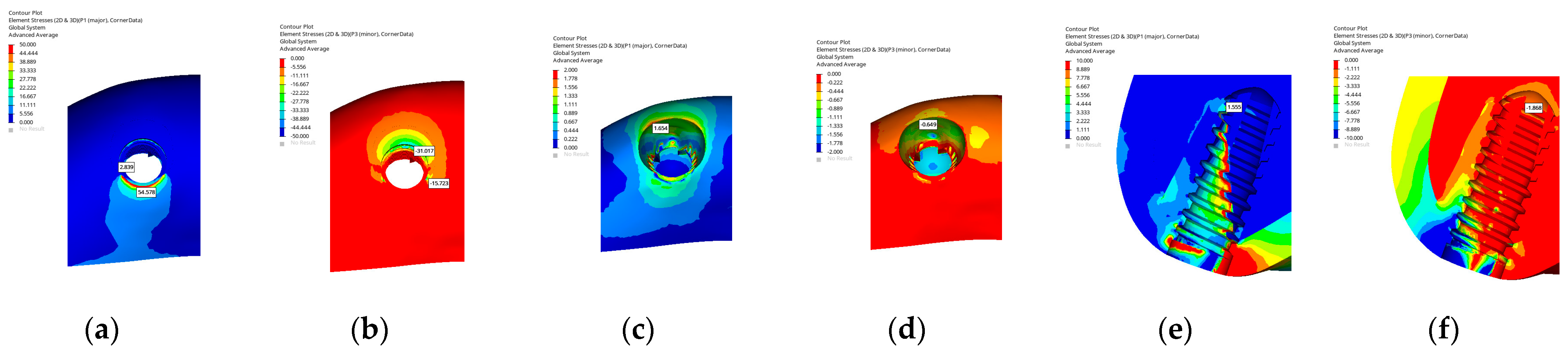
In the B2 model with a cylindrical macrogeometry, the maximum principal stress in the cortical bone was concentrated on the palatal wall (54.578 MPa), whereas the minimum stress was observed on the buccal side corresponding to the grafted region (31.017 MPa). In the cancellous bone, the maximum stress was distributed around the socket walls (1.654 MPa), whereas the minimum stress was observed in the buccal and mesial regions (0.649 MPa). From the lateral perspective, the grafted buccal area also received a significant load. Overall, stress was mainly concentrated on the buccal side due to the loading direction. Also, the cylindrical design yielded slightly higher stress around the palatal crest compared with the tapered form.
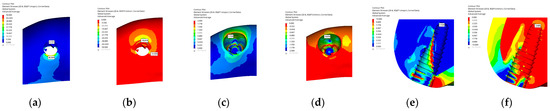
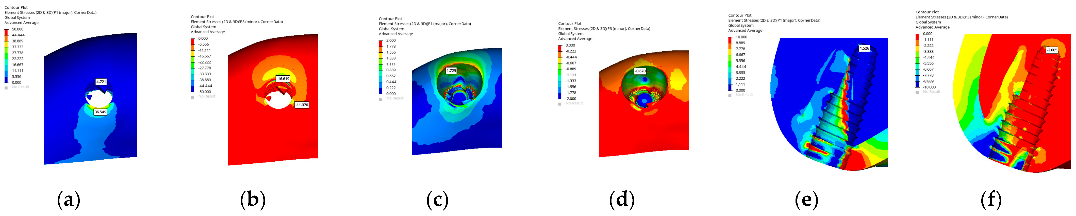
In the C1 implant model with a conical macrogeometry, the maximum principal stress in the cortical bone was concentrated on the palatal wall (36.549 MPa), whereas the minimum stress occurred on the buccal side corresponding to the grafted area (16.619 MPa). In the cancellous bone, the maximum stress was distributed around the socket walls (1.729 MPa), whereas the minimum stress was observed in the buccal grafted region (0.670 MPa). From the lateral view, the grafted buccal area displayed higher stress concentration. Stress was concentrated on the buccal side according to the loading direction, but the tapered design had more even distribution along the implant body.
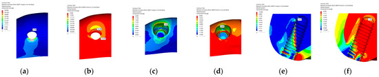
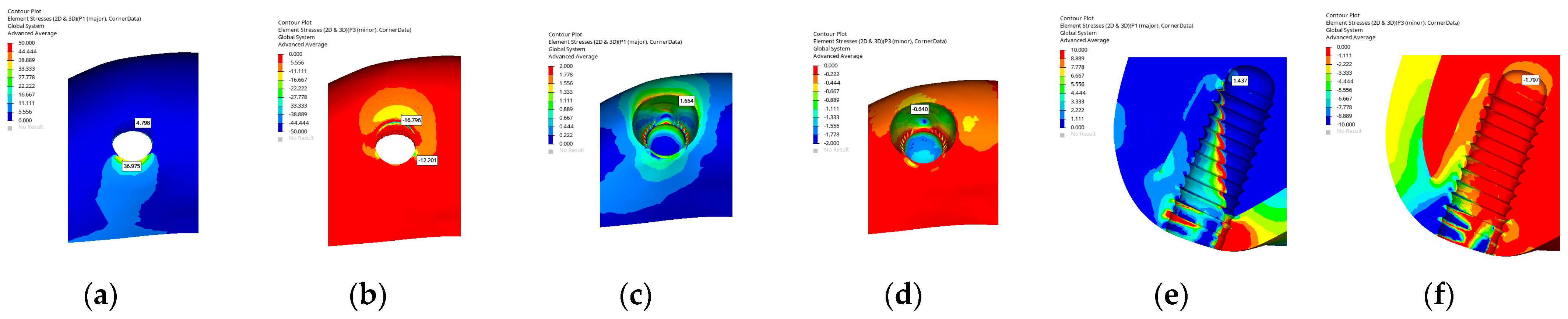
In the C2 implant model with a cylindrical macrogeometry, the maximum principal stress in the cortical bone was concentrated on the palatal wall (36.975 MPa), whereas the minimum stress was observed on the buccal side corresponding to the grafted region (16.796 MPa). In the cancellous bone, the maximum stress was distributed around the socket walls (1.654 MPa), whereas the minimum stress occurred in the buccal and mesial regions (0.640 MPa). From the lateral view, the grafted buccal area exhibited higher stress concentration. Stress was mainly accumulated on the buccal side according to the loading direction. The cylindrical design resulted in a more localized stress distribution compared with the tapered form.
Overall, when the implant models were grouped according to macrogeometry, distinct design-dependent stress distribution patterns were observed during immediate implant placement. Cylindrical designs generally exhibited more localized stress concentration in the crestal cortical bone and buccal region along the primary loading direction, whereas tapered and hybrid designs tended to distribute stresses more evenly along the implant body and toward the apical region. Across all implant systems, hybrid macrogeometries demonstrated intermediate behavior, combining coronal stress distribution characteristics of cylindrical designs with the apical load transfer features of tapered implants. The minimum–maximum principal stress (MPa) values in IIP are shown in Table 2 and Figure 2, Figure 3, Figure 4, Figure 5, Figure 6 and Figure 7.
Table 2.
Minimum–maximum principal stress in cortical bone, cancellous bone, and apex of implant (MPa) in immediate implant placement.
Figure 2.
Maximum and minimum principal stresses in the A1 implant model for the cortical bone (a,b), cancellous bone (c,d), and apex of the implant (e,f).
Figure 3.
Maximum and minimum principal stresses in the A2 implant model for the cortical bone (a,b), cancellous bone (c,d), and apex of the implant (e,f).
Figure 4.
Maximum and minimum principal stresses in the B1 implant model for the cortical bone (a,b), cancellous bone (c,d), and apex of the implant (e,f).
Figure 5.
Maximum and minimum principal stresses in the B2 implant model for the cortical bone (a,b), cancellous bone (c,d), and apex of the implant (e,f).
Figure 6.
Maximum and minimum principal stresses in the C1 implant model for the cortical bone (a,b), cancellous bone (c,d), and apex of the implant (e,f).
Figure 7.
Maximum and minimum principal stresses in the C2 implant model for the cortical bone (a,b), cancellous bone (c,d), and apex of the implant (e,f).
3.1.2. Stress Values in DIP
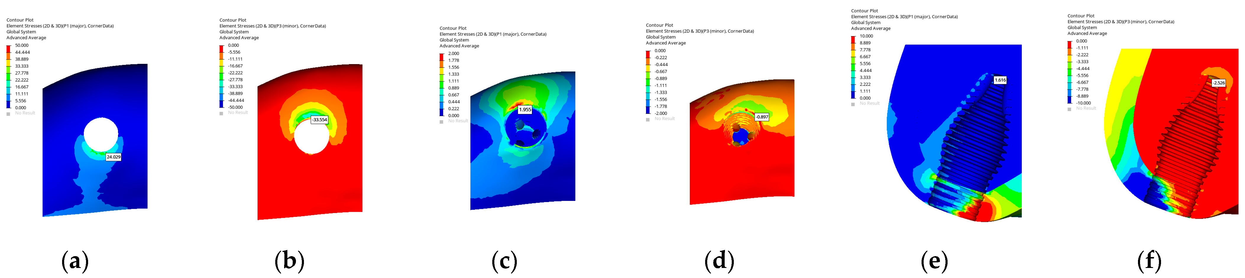
In the A1 implant model with a hybrid macrogeometry combining a conical apical portion with a cylindrical coronal design, the maximum principal stress in the cortical bone was observed on the palatal side (24.09 MPa), while the minimum stress was located in the buccal region (33.554 MPa). In the cancellous bone, both maximum (1.955 MPa) and minimum (0.897 MPa) principal stresses were concentrated at the buccal side. At the apex of the implant, both tensile and compressive stresses were moderately distributed, indicating a balanced load transfer toward the apical region.
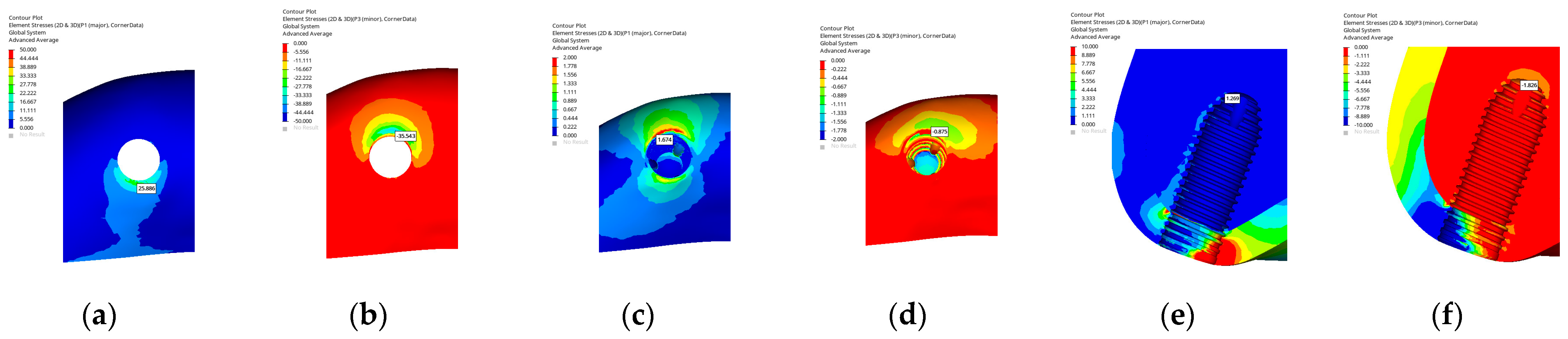
In the A2 implant model with a cylindrical implant macrogeometry, the maximum principal stress in the cortical bone was observed on the palatal side (25.886 MPa), whereas the minimum stress appeared on the buccal side (35.543 MPa). In the cancellous bone, both the maximum (1.674 MPa) and minimum (0.875 MPa) principal stresses were concentrated in the buccal region. At the apex of the implant, the stress distribution was relatively balanced, indicating uniform load transfer toward the apical region.
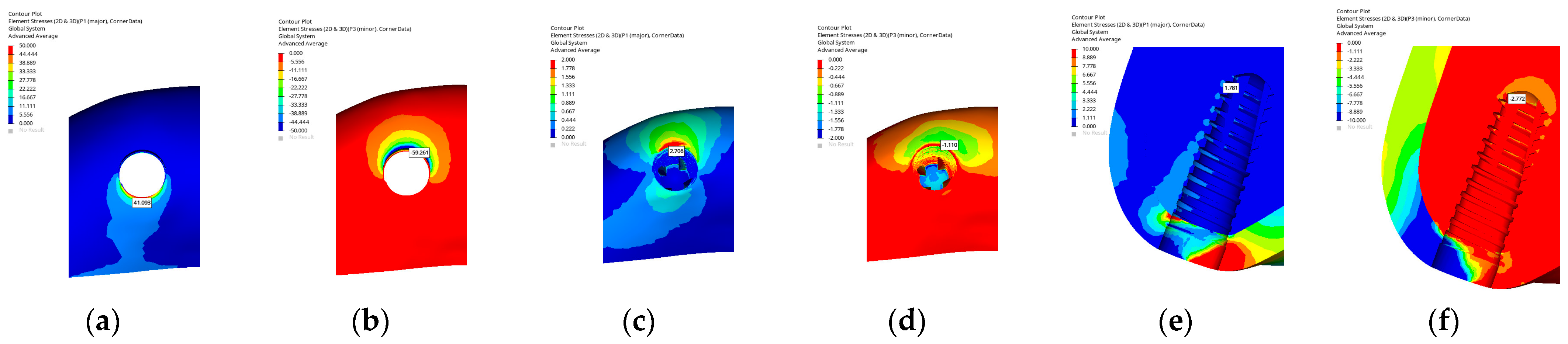
In the B1 implant model, the implant exhibited a conical macrogeometry. In the cortical bone, the maximum principal stress was concentrated on the palatal wall in the coronal region (41.093 MPa), whereas the minimum stress was observed on the buccal side (59.261 MPa). In the cancellous bone, both the maximum (2.706 MPa) and minimum (1.110 MPa) principal stresses were located on the buccal side, indicating that stress accumulation predominantly occurred in this region. At the apex of the implant, the stress distribution was relatively balanced, demonstrating homogeneous load transfer along the implant body.
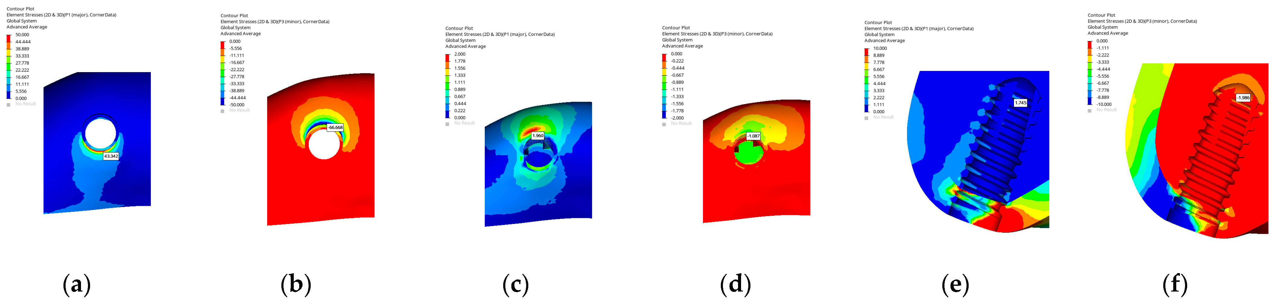
In the B2 implant model, the implant exhibited a cylindrical macrogeometry with a straight body profile. In the cortical bone, the maximum principal stress was concentrated on the palatal wall in the coronal region (43.342 MPa), whereas the minimum stress was observed on the buccal side (66.668 MPa). In the cancellous bone, both the maximum (1.960 MPa) and minimum (1.087 MPa) principal stresses were located on the buccal side, indicating localized stress accumulation in this area. At the apex of the implant, the stress distribution was relatively balanced, suggesting uniform load transmission toward the apical region.
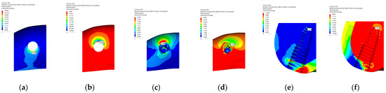
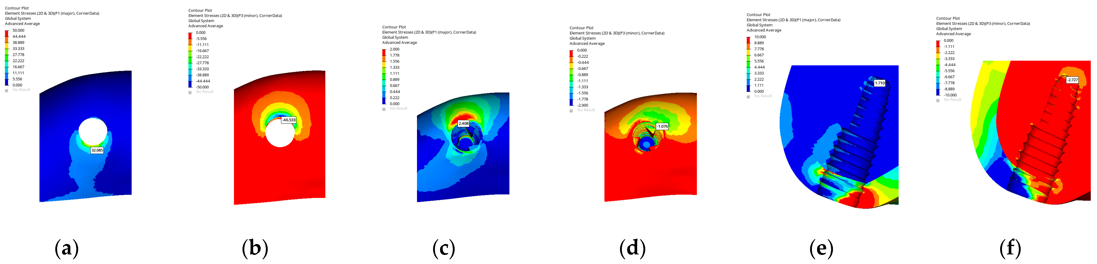
In the C1 implant model, the implant presented a tapered (conical) macrogeometry characteristic of the BLT design. In the cortical bone, the maximum principal stress was concentrated on the palatal wall in the coronal region (32.085 MPa), whereas the minimum stress appeared on the buccal side (46.533 MPa). In the cancellous bone, both the maximum (2.408 MPa) and minimum (1.710 MPa) principal stresses were located on the buccal side. At the apex of the implant, the stress distribution was confined to a smaller area, displaying a relatively balanced load transfer toward the apical region.
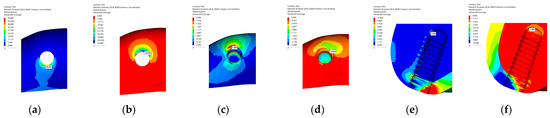
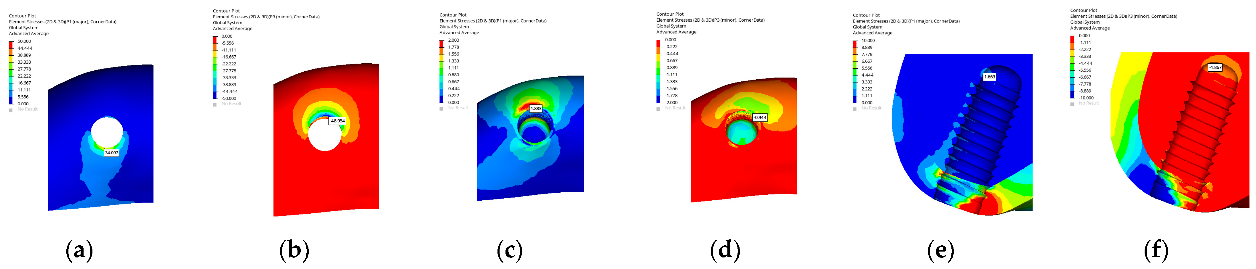
In the C2 implant model, the implant exhibited a cylindrical macrogeometry with a parallel-walled body design. In the cortical bone, the maximum principal stress was concentrated on the palatal wall in the coronal region (34.097 MPa), whereas the minimum stress was observed on the buccal side (48.954 MPa). In the cancellous bone, both the maximum (1.883 MPa) and minimum (0.944 MPa) principal stresses were located on the buccal side. At the apex of the implant, the stress distribution extended along the apex of the implant, indicating a continuous and balanced load transfer toward the apical region.
Overall, when the implant models were evaluated according to macrogeometry under delayed implant placement conditions, consistent design-dependent stress distribution patterns were observed across all implant systems. Tapered designs generally exhibited a more favorable dissipation of stresses toward the apical region, resulting in reduced stress concentration in the crestal cortical bone, whereas cylindrical designs tended to show more localized stress accumulation along the buccal surface and coronal cortical region. Hybrid designs demonstrated intermediate stress distribution characteristics, combining relatively balanced apical load transfer with moderated cortical stress levels. The minimum–maximum principal stress (MPa) values in DIP are shown in Table 3 and Figure 8, Figure 9, Figure 10, Figure 11, Figure 12 and Figure 13.
Table 3.
Minimum–maximum principal stress in the cortical bone, cancellous bone, and apex of the implant (MPa) in delayed implant placement.
Figure 8.
Maximum and minimum principal stresses in the A1 implant model for the cortical bone (a,b), cancellous bone (c,d), and apex of the implant (e,f).
Figure 9.
Maximum and minimum principal stresses in the A2 implant model for the cortical bone (a,b), cancellous bone (c,d), and apex of the implant (e,f).
Figure 10.
Maximum and minimum principal stresses in the B1 implant model for the cortical bone (a,b), cancellous bone (c,d), and apex of the implant (e,f).
Figure 11.
Maximum and minimum principal stresses in the B2 implant model for the cortical bone (a,b), cancellous bone (c,d), and apex of the implant (e,f).
Figure 12.
Maximum and minimum principal stresses in the C1 implant model for the cortical bone (a,b), cancellous bone (c,d), and apex of the implant (e,f).
Figure 13.
Maximum and minimum principal stresses in the C2 implant model for the cortical bone (a,b), cancellous bone (c,d), and apex of the implant (e,f).
3.2. Strain Values in Delayed and Immediate Implant Placements
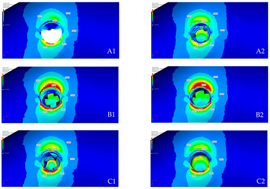
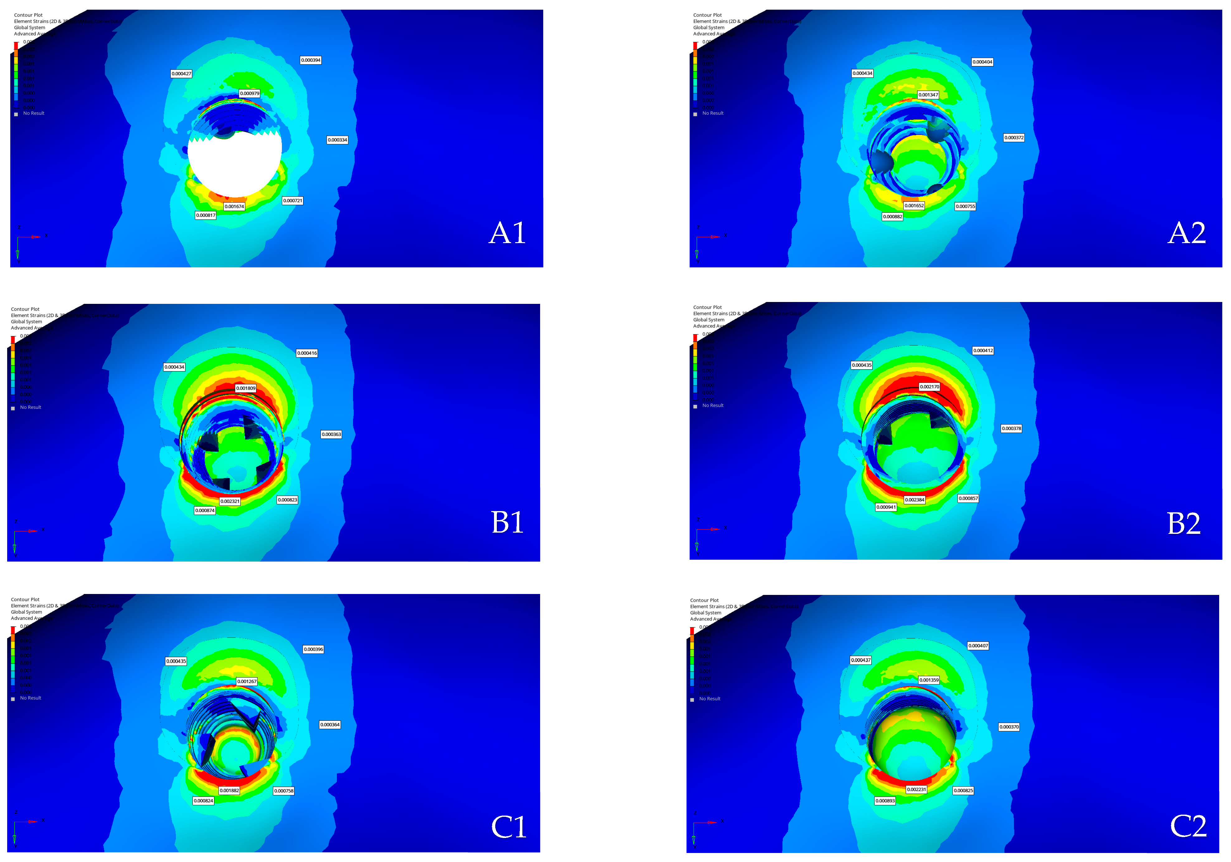
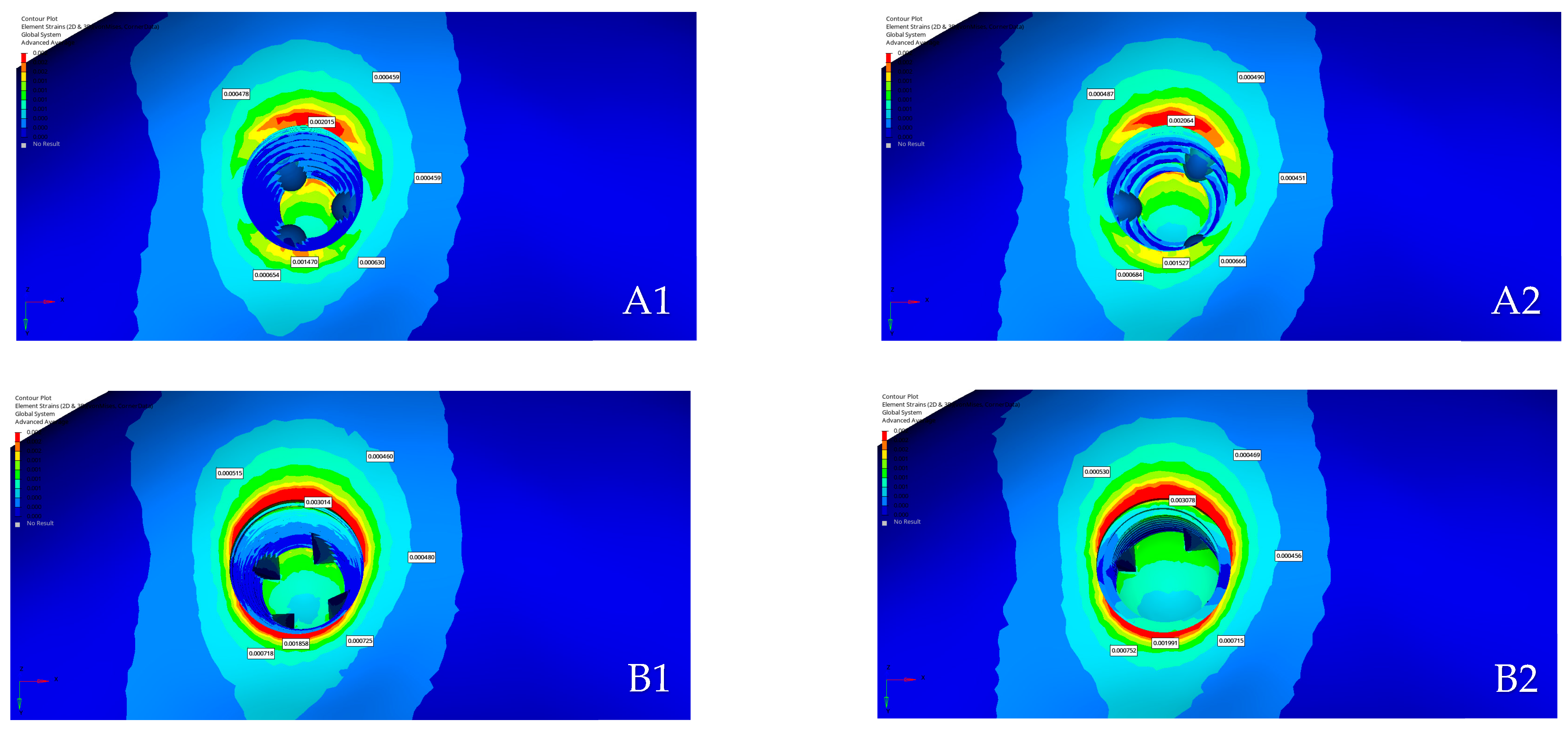
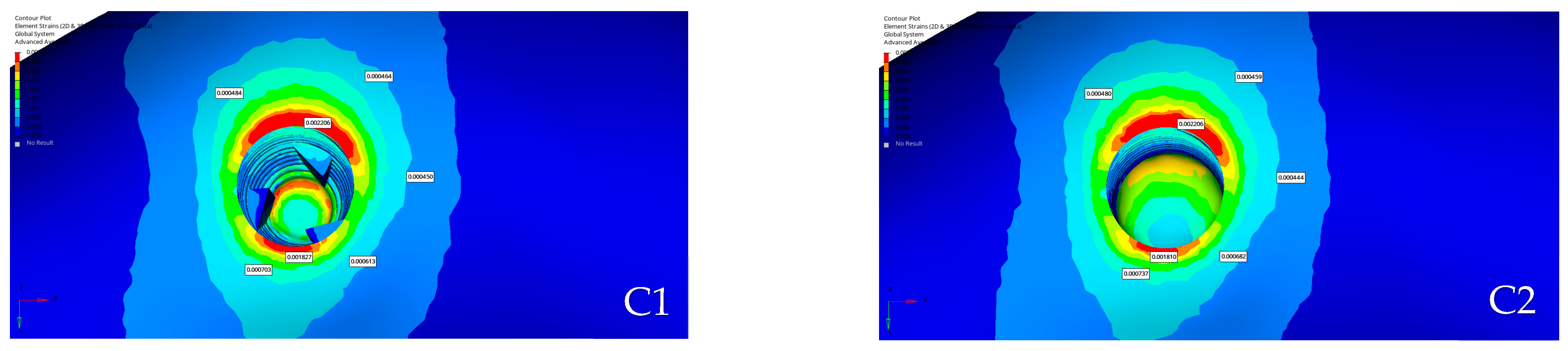
The points at which strain was measured were selected at equal distances from the implant surface, ensuring that the same reference locations were used for all implant models. The strain values in delayed and immediate implant placements are shown in Table 4 and Figure 14 and Figure 15.
Table 4.
Strain values (μϵ) in delayed and immediate implant placements.
Figure 14.
Distribution of strain values in immediate implant placement models: (A1): Southern Inverta; (A2): Southern Cylindrical; (B1): Thommen Contact; (B2): Thommen Element; (C1): Straumann BLT; (C2): Straumann BL.
Figure 15.
Distribution of strain values in delayed implant placement models: (A1): Southern Inverta; (A2): Southern Cylindrical; (B1): Thommen Contact; (B2): Thommen Element; (C1): Straumann BLT; (C2): Straumann BL.
3.3. Comparison of Models
In DIP, the maximum tensile and compressive stresses in all models were predominantly concentrated in the cortical bone rather than in the cancellous bone, indicating the greater rigidity and load-bearing role of the cortical structure. Among the six implant designs, models with tapered macrogeometry (A1, B1, and C1) exhibited a more homogeneous stress distribution and reduced concentration in the crestal cortical region compared with cylindrical designs (A2, B2, and C2). In contrast, cylindrical implants demonstrated slightly higher stress accumulation on the buccal side of the cortical and cancellous bones. At the apical region, all models showed balanced stress transfer along the implant apex, suggesting stable force transmission under oblique loading. From a biomechanical perspective, tapered implants appeared to provide more favorable load distribution, potentially minimizing crestal bone stress and enhancing long-term peri-implant bone stability in DIP.
In IIP, the maximum principal stresses were predominantly concentrated in the cortical bone, particularly along the palatal wall, whereas the minimum stresses were located on the buccal side corresponding to the grafted area. In the cancellous bone, stress was generally distributed around the socket walls and extended toward the mesial region, whereas the buccal grafted zone exhibited lower stress magnitudes. Among the implant designs, tapered geometries (A1, B1, and C1) exhibited more uniform stress transfer and reduced crestal concentration compared with cylindrical forms (A2, B2, and C2), which showed slightly higher stress accumulation near the palatal crest and socket margins. The presence of graft material on the buccal side contributed to stress absorption and participated in load sharing during immediate loading. Overall, stress was mainly concentrated on the buccal side, whereas tapered implants demonstrated a more favorable and homogeneous biomechanical response under IIP conditions.
In DIP, strain values were mainly distributed around the socket walls, particularly at the buccal and palatal regions, reflecting the direction of the applied oblique load. Among the models, the aggressive designs (A1, B1, and C1) exhibited lower strain magnitudes and a more homogeneous distribution compared with the cylindrical designs (A2, B2, and C2), which showed higher localized strain values on the buccal aspect. The overall pattern indicated that tapered configurations facilitated smoother load transfer across the peri-implant bone, potentially reducing localized deformation in the crestal cortical region. Despite these variations among implant geometries, all strain values remained within the physiological limits described by Frost’s mechanostat theory, without exceeding the thresholds for microdamage or pathological remodeling [16]. This suggests that each model maintained a biomechanically favorable strain environment under conventional loading conditions.
In IIP, the strain values were concentrated around the buccal and palatal regions, reflecting the direction of applied loading. Among the designs, the A1 model exhibited the lowest strain values, followed by the C1 model with a similarly balanced distribution due to its tapered geometry. Higher strain levels were observed in the B1 and B2 models, particularly in B2, which showed the greatest concentration among all designs. Despite these differences, none of the measured strain values exceeded the pathological threshold defined by Frost’s mechanostat theory, indicating that all models remained within the physiological range for bone adaptation under immediate loading conditions.
Overall, tapered (aggressive) designs generally demonstrated more homogeneous stress and strain distributions, with reduced concentration in the crestal cortical bone compared with cylindrical (passive) designs, which tended to exhibit more localized stress and strain accumulation, particularly along the buccal and coronal regions. Hybrid configurations showed intermediate biomechanical behavior, combining characteristics of both tapered and cylindrical geometries. Importantly, these geometry-dependent patterns were observed consistently across different implant systems, indicating that implant macrogeometry played a dominant role in governing peri-implant biomechanical response under oblique loading.
4. Discussion
The use of IIP protocols in the anterior maxilla has become a common clinical practice, offering advantages in terms of aesthetic preservation and reduced overall treatment duration. The long-term success of implants in this region depends on several factors, including implant position, insertion angle, prosthetic design, implant macrogeometry, bone thickness, soft tissue conditions, and loading protocol. Recently, manufacturers have increasingly recommended the use of implants with aggressive macrogeometries, particularly in immediate implantation and immediate loading procedures. However, comparative data evaluating aggressive and passive implant designs under these conditions are still inadequate. Therefore, a single-tooth loss model in the anterior maxilla was simulated in this study to assess stress and strain distributions in peri-implant bone using FEM, comparing aggressive and passive implant designs under both immediate implantation and delayed implantation with immediate loading scenarios.
In this study, a 3D FEM method was used to compare six different implant models (A1, A2, B1, B2, C1, and C2) in terms of stress and strain values in the maxillary anterior segment. For clarity, the implant models were grouped according to implant system, with A1–A2 representing the first group, B1–B2 the second group, and C1–C2 the third group, each comprising an aggressive and a passive macrogeometric design. A bone segment and an extraction socket were modeled to represent the anterior maxillary region and the central incisor, with dimensions selected to ensure that boundary effects would not influence the stress distribution at the region of interest. Moreover, both loading and boundary conditions were simplified due to the partial modeling of the maxilla.
The central incisors were loaded obliquely (135°) in the present study to reproduce contacts that occurred during mastication. A single static oblique load was applied, representing a simplification of masticatory loading. The total oblique force applied was 120 N, which was selected based on the average single-tooth bite force reported for the maxillary central incisor in healthy young adults by Ferrario et al., who measured mean values of approximately 94 N in women and 146 N in men, as well as by Apostolov et al., who reported comparable frontal maximum bite force values of approximately 97 N in women and 138 N in men [15,17]. The present study has several limitations that should be considered when interpreting the findings. In the finite element model, cortical and cancellous bone tissues and graft materials were assumed to be homogeneous, isotropic, and linearly elastic materials. In the IIP models, the gap formed between the implant surface and the buccal socket wall was filled with a xenograft material. The mechanical behavior of xenograft materials remains variably defined in the literature, with reported properties ranging widely depending on graft type, processing method, and modeling assumptions. In the present study, the xenograft region was intentionally modeled to represent a relatively softer bone environment compared with cortical bone. Accordingly, due to its lower stiffness relative to cortical bone, the xenograft was associated with lower stress levels under functional loading. Although bone and graft exhibits anisotropic and heterogeneous behavior in vivo, these assumptions are commonly adopted in finite element analyses to ensure numerical convergence and to enable consistent comparisons between different implant designs. In addition, complete osseointegration was assumed at the implant–bone interface in the delayed implantation models, while a frictional contact condition was defined for the immediate loading models [18]. This approach was adopted because biological stability at the implant–bone interface is largely established under healed conditions, allowing load transfer to be reasonably represented by a bonded contact assumption, whereas in immediate implantation, osseointegration has not yet occurred and the mechanical interaction between bone and implant is primarily governed by friction. Although these assumptions do not fully capture the complex biological and time-dependent behavior of the bone–implant interface, they are widely accepted in numerical analyses to ensure model stability, numerical convergence, and consistency between simulation scenarios. These simplifications may influence the absolute stress and strain magnitudes; however, they allow a controlled comparative evaluation of implant macrogeometries under standardized conditions. These assumptions are widely adopted in comparative finite element studies and allow for controlled evaluation of relative design effects under standardized conditions. The primary focus of the present study was therefore not the detailed mechanical characterization of the graft material itself, but rather the comparative evaluation of different implant macrogeometries under standardized conditions. Although the use of average force values and idealized material properties does not fully reflect the complexity of biological tissues, the aforementioned assumptions are widely accepted in finite element analyses. In this study, the bone and implant structures were modeled under ideal conditions. Therefore, interpreting the results in a comparative manner by evaluating the differences in stress distribution and strain values among various implant designs is more appropriate than focusing on absolute stress values.
The obtained data showed that the maximum and minimum principal stress values in all implant models were significantly higher in the cortical bone compared with the cancellous bone. This finding was related to the more rigid structure of the cortical bone and its greater role in load transfer. Previous studies reported that pathological bone resorption was associated with stress values above 100–120 MPa in the cortical bone and 15–20 MPa in the cancellous bone [16,19,20]. The values obtained in this study were well below these limits, indicating that the tested implant designs could be considered biomechanically safe in terms of stress distribution within the peri-implant bone. None of the groups exhibited stress levels in the cortical or cancellous bone that exceeded the pathological level.
The strain values obtained for all implant models were evaluated according to Frost’s mechanostat theory [16]. The reference points selected for strain measurement were taken from identical coordinates at equal distances from the implant surface, and therefore did not represent the absolute maximum strain values but were used solely for comparative evaluation among models. In both DIP and IIP conditions, the strain magnitudes remained within the physiological range for normal bone remodeling, without exceeding the pathological threshold. According to Frost’s mechanostat theory, bone tissue remains in a physiological state when strain levels are between approximately 200 and 2500 microstrain (με), whereas values below this range may induce disuse atrophy, and those exceeding 4000 με can lead to microdamage and pathological bone resorption. The results of the present study demonstrated that none of the analyzed models exceeded these critical thresholds, indicating that the peri-implant bone was subjected to physiological loading conditions [16].
The stress distribution patterns revealed notable differences between the aggressive and passive configurations of each implant system under oblique functional loading in the delayed placement scenario. When the two designs were compared within the first group, the hybrid geometry exhibited lower stress concentration on the cervical cortical bone compared with its passive counterpart. The lower cervical stress observed in the hybrid model could be attributed to its narrower coronal design compared with the implant body. The narrower coronal neck and the expanded implant body promote a redistribution of functional loads toward the body of the implant, allowing stresses to be accommodated over a larger surface area. This configuration may helped reduce load concentration in the neck region. This reduction around the implant neck suggested a more favorable transfer of load from the coronal portion to the surrounding bone, potentially minimizing the risk of crestal bone resorption often associated with excessive cervical stresses. From a clinical perspective, lower stress levels at the implant neck are particularly relevant, as excessive cervical stress has been associated with marginal bone loss and early crestal bone remodeling around dental implants. Therefore, the observed reduction in cervical stress in tapered and hybrid designs may contribute to improved crestal bone preservation in clinical practice. These findings were consistent with the findings of Baggi et al. (2008), who reported that wider implant diameters and platform-switching configurations effectively reduced crestal stress and promoted a more favorable load distribution in the peri-implant bone [21]. The same trend was observed in the second group, where the conical configuration distributed the stresses more evenly along the implant body, whereas the cylindrical design demonstrated a more localized pattern at the palatal crest. This difference can be explained by the capacity of tapered geometries to distribute functional loads progressively along the implant axis, redirecting stresses toward the apical region rather than concentrating them at the implant neck and crestal cortical bone. Likewise, in the third group, the tapered form exhibited slightly more homogeneous stress propagation compared with its parallel-walled equivalent. In the finite element study conducted by Paracchini et al., two implants with identical dimensions but different macrogeometries were compared to evaluate how body shape influenced stress transmission to the surrounding bone. Their analysis revealed that the tapered body with a reverse-conical collar exhibited a more favorable biomechanical behavior compared with the cylindrical configuration, producing lower crestal cortical stresses and promoting a smoother, apically directed transfer of loads to the surrounding bone. This pattern of stress dissipation suggested that tapered macrogeometries might contribute to a more homogeneous distribution of functional forces and potentially reduce the risk of crestal bone resorption under both axial and oblique loading conditions [22]. These comparative findings indicated that implants incorporating a tapered or hybrid geometry could moderate the concentration of stress and strain at the implant neck, contributing to has potential to reduce marginal bone resorption during functional loading.
When the more aggressive designs were compared with each other, all three demonstrated similar stress distributions along the implant body, although the cervical region of hybrid geometry exhibited slightly lower strain values, reflecting a more uniform deformation pattern around the buccal and palatal walls. The reduced cervical strain observed in the hybrid design can be explained by its macrogeometry, which limits stress uptake at the cervical region and promotes load accommodation along the implant body rather than at the implant neck. This indicated that the load transfer around hybrid geometries might be less disruptive to the crestal bone compared with other aggressive configurations. Clinically, a less disruptive load transfer at the crestal region may help maintain marginal bone levels during functional loading, especially in situations where bone quality is compromised or early loading protocols are applied [23]. Despite these differences, the apical stress distributions were similar across the aggressive models, suggesting that all maintained comparable mechanical anchorage and primary stability. The consistent stress behavior in the apical zone implied that reducing cervical stress in these designs did not compromise fixation at the apex but rather promoted balanced load sharing between the crest and the apical bone. These findings indicate that, although stresses are reduced at the cervical region, apical stability remains comparable across designs. Although cervical stresses are reduced, the similarity in apical stress distributions indicates that apical stability is preserved. This can be attributed to the tapered apical geometry of the hybrid design, which ensures effective bone engagement and mechanical anchorage in the apical region.
The general stress distribution pattern followed a similar trend but with slightly decreased magnitudes under immediate implantation conditions due to the presence of graft material and the absence of full osseointegration. In immediate implant conditions, implant macrogeometry becomes mechanically important, as tapered and hybrid designs facilitate more effective load transfer within the surrounding bone. When comparing the designs within the same system, the aggressive configuration of first group again demonstrated a lower stress concentration at the implant neck compared with its passive design. The cervical bone surrounding hybrid geometry exhibited a more favorable stress profile, with smoother stress transitions on both buccal and palatal sides. This behavior can be explained by the macrogeometric differences in load transfer and stiffness distribution between aggressive and passive designs. The narrower coronal profile and convergent geometry of the aggressive configuration promote a more gradual engagement with the surrounding bone, allowing functional loads to be redistributed along the implant body rather than being abruptly transferred to the cervical cortical region. This reduction implied a potentially lower risk of crestal bone resorption during early healing. Such a biomechanical environment may be advantageous during the early healing phase, as reduced cervical stress may support more favorable bone adaptation and osseointegration under immediate loading conditions [24]. In contrast, cylindrical design of first group showed greater localization of stress on the palatal side, indicating a more abrupt load transfer toward the crestal bone. A comparable relationship was noted between second group, where the conical model exhibited a smoother stress distribution along the implant body, whereas the cylindrical configuration concentrated stresses closer to the cortical crest. Aggressive design of third group displayed a balanced stress pattern between the coronal and apical zone, whereas cylindrical design retained slightly higher loading in the cervical region. These results indicate that tapered and hybrid geometries lower cervical stress by spreading loads along the implant. This observation was in line with the findings of Heimes et al. reporting that tapered and conical implants provided greater primary stability and more favorable overall load distribution compared with cylindrical implants [25]. These geometries are considered advantageous for immediate placement, particularly in the anterior maxilla, where they may help achieve more balanced stress transfer.
When the aggressive designs were evaluated together, their biomechanical behavior appeared consistent with the delayed scenario. Among these, the cervical bone surrounding the hybrid model of first group experienced slightly lower stresses, suggesting a more homogeneous load transfer that might be less detrimental to the crestal bone. In contrast, the passive designs demonstrated higher stress accumulation on the cervical cortical bone, particularly at the palatal crest, indicating less effective load dissipation under oblique loading. Despite these differences in the neck region, apical stress distributions were comparable among all aggressive models, confirming that the designs provided similar mechanical anchorage and primary stability. Likewise, the passive geometries displayed consistent apical stress behavior, suggesting that although their cervical stresses were higher, their apical engagement remained sufficient for initial stability. The findings of the present study were in agreement with those of Rocha dos Reis-Neta et al., who compared tapered and parallel-walled implant macrogeometries and found that tapered designs provided higher primary stability during immediate and early loading phases, whereas long-term survival and marginal bone levels remained comparable between both configurations [26]. To provide an overall overview, the key biomechanical trends associated with different implant macrogeometries under immediate and delayed placement protocols are summarized in Table 5 and Table 6.
Table 5.
Conceptual summary of biomechanical trends under immediate implant placement (IIP).
Table 6.
Conceptual summary of biomechanical trends under delayed implant placement (DIP).
Overall, the findings of the present study indicate that implant macrogeometry plays a central role in peri-implant stress and strain distribution under both immediate and delayed loading conditions. Notably, all calculated stress and strain values remained within physiological limits and did not exceed thresholds associated with pathological bone remodeling, as the primary aim of this study was to provide a comparative biomechanical assessment. Within these findings, tapered and hybrid designs consistently demonstrated reduced stress concentration in the cervical cortical bone compared with cylindrical configurations, a behavior that can be attributed to differences in load transfer mechanisms and stress distribution along the implant body as a consequence of implant macrogeometry. The convergent geometry and narrower coronal profile of these designs promote a more progressive engagement with the surrounding bone, allowing functional loads to be redistributed toward the apical region rather than being transferred to the crestal cortical bone. Accordingly, the present findings should be interpreted as comparative biomechanical trends related to implant macrogeometry rather than as directly predictive outcomes for all implant systems or clinical situations.
5. Conclusions
This study suggests that, although all models exhibited comparable stress and strain magnitudes, the implant with a hybrid macrogeometry—characterized by a narrower cervical collar, a wider mid-body, and a tapered apical portion—was associated with distinct biomechanical trends. This configuration may be associated with lower stress and strain concentrations in the cervical region, potentially contributing to a biomechanically favorable environment for crestal bone preservation, while not compromising apical load transfer and mechanical anchorage. Although further clinical validation is required, the present finite element analysis provides biomechanical support for aggressive geometries as a design concept capable of balancing cervical stress moderation with initial mechanical anchorage under functional loading conditions.
Author Contributions
Conceptualization, M.E.K. and N.B.B.; methodology, M.E.K. and N.B.B.; validation, M.E.K. and N.B.B.; formal analysis, M.E.K. and N.B.B.; investigation, M.E.K. and N.B.B.; resources, M.E.K. and N.B.B.; writing—original draft preparation, M.E.K. and N.B.B.; writing—review and editing, M.E.K. and N.B.B.; visualization, M.E.K. and N.B.B.; supervision, N.B.B. All authors have read and agreed to the published version of the manuscript.
Funding
This study was supported by the Scientific Research Projects Coordination Unit of Istanbul University (Project Number—TDK-2024-40876).
Institutional Review Board Statement
Not applicable.
Informed Consent Statement
This study did not involve any human participants, patients, or identifiable personal data. All anatomical models and input parameters used in the finite element analysis were selected based on values reported in the relevant literature. No individual or subject-specific data were used, and therefore no informed consent was obtained.
Data Availability Statement
The data presented in this study are available from the corresponding author on request.
Conflicts of Interest
The authors declare no conflicts of interest. The funders had no role in the design of the study; in the collection, analyses, or interpretation of data; in the writing of the manuscript; or in the decision to publish the results.
Abbreviations
The following abbreviations are used in this manuscript:
| IIP | Immediate implant placement |
| DIP | Delayed implant placement |
| BL | Bone level |
| BLT | Bone level tapered |
| GPa | Giga pascal |
| DICOM | Digital Imaging and Communications in Medicine |
| MPa | Mega pascal |
| ISQ | Implant stability quotient |
| N | Newton |
| με | Microstrain |
References
- Hämmerle, C.H.; Chen, S.T.; Wilson, T.G., Jr. Consensus statements and recommended clinical procedures regarding the placement of implants in extraction sockets. Int. J. Oral. Maxillofac. Implant. 2004, 19, 26–28. [Google Scholar]
- Lazzara, R.J. Immediate implant placement into extraction sites: Surgical and restorative advantages. Int. J. Periodont. Restor. Dent. 1989, 9, 332–343. [Google Scholar]
- Araújo, M.G.; Lindhe, J. Ridge alterations following tooth extraction with and without flap elevation: An experimental study in the dog. Clin. Oral. Implant. Res. 2009, 20, 545–549. [Google Scholar] [CrossRef] [Scilit] [PubMed]
- Lang, N.P.; Pun, L.; Lau, K.Y.; Li, K.Y.; Wong, M.C. A systematic review on survival and success rates of implants placed immediately into fresh extraction sockets after at least 1 year. Clin. Oral. Implant. Res. 2012, 23, 39–66. [Google Scholar] [CrossRef] [Scilit] [PubMed]
- Chen, S.T.; Buser, D. Clinical and esthetic outcomes of implants placed in postextraction sites. Int. J. Oral. Maxillofac. Implant. 2009, 24, 186–217. [Google Scholar]
- Araújo, M.G.; Lindhe, J. Dimensional ridge alterations following tooth extraction. An experimental study in the dog. J. Clin. Periodontol. 2005, 32, 212–218. [Google Scholar] [CrossRef] [Scilit] [PubMed]
- Cannizzaro, G.; Leone, M.; Consolo, U.; Ferri, V.; Esposito, M. Immediate functional loading of implants placed with flapless surgery versus conventional implants in partially edentulous patients: A 3-year randomized controlled clinical trial. Int. J. Oral. Maxillofac. Implant. 2008, 23, 867–875. [Google Scholar]
- Le Guéhennec, L.; Soueidan, A.; Layrolle, P.; Amouriq, Y. Surface treatments of titanium dental implants for rapid osseointegration. Dent. Mater. 2007, 23, 844–854. [Google Scholar] [CrossRef] [Scilit]
- Orozco-Varo, A.; Arroyo-Cruz, G.; Martínez-De-Fuentes, R.; Jiménez-Castellanos, E. Biometric analysis of the clinical crown and the width/length ratio in the maxillary anterior region. J. Prosthet. Dent. 2015, 113, 565–570.e2. [Google Scholar] [CrossRef] [Scilit]
- Jolicoeur, H.R.; Camargo, G.A.; Stephenson, T.G.; Zhang, W. Accuracy of Implant Size Prediction Based on Edentulous Ridge Dimension on Cone-beam Computed Tomography—A Retrospective Study. Ann. Maxillofac. Surg. 2024, 14, 187–191. [Google Scholar] [CrossRef] [Scilit]
- Meijer, H.J.A.; Boven, C.; Delli, K.; Raghoebar, G.M. Is there an effect of crown-to-implant ratio on implant treatment outcomes? A systematic review. Clin. Oral. Implant. Res. 2018, 29, 243–252. [Google Scholar] [CrossRef] [Scilit] [PubMed]
- Kwon, B.G.; Kim, S.G. Finite element analysis of different bone substitutes in the bone defects around dental implants. Implant. Dent. 2006, 15, 254–264. [Google Scholar] [CrossRef] [Scilit] [PubMed]
- Lee, J.H.; Jang, H.Y.; Lee, S.Y. Finite Element Analysis of Dental Implants with Zirconia Crown Restorations: Conventional Cement-Retained vs. Cementless Screw-Retained. Materials 2021, 14, 2666. [Google Scholar] [CrossRef] [Scilit]
- Bölükbaşı, N.; Yeniyol, S. Number and localization of the implants for the fixed prosthetic reconstructions: On the strain in the anterior maxillary region. Med. Eng. Phys. 2015, 37, 431–445. [Google Scholar] [CrossRef] [Scilit] [PubMed]
- Ferrario, V.F.; Sforza, C.; Serrao, G.; Dellavia, C.; Tartaglia, G.M. Single tooth bite forces in healthy young adults. J. Oral. Rehabil. 2004, 31, 18–22. [Google Scholar] [CrossRef] [Scilit]
- Frost, H.M. Bone’s mechanostat: A 2003 update. Anat. Rec. Discov. Mol. Cell Evol. Biol. 2003, 275, 1081–1101. [Google Scholar] [CrossRef] [Scilit]
- Apostolov, N.; Chakalov, I.; Drajev, T. Measurement of the Maximum Bite Force in the Natural Dentition with a Gnathodynamometer. J. Med. Dent. Pract. 2014, 1, 70–75. [Google Scholar] [CrossRef] [Scilit]
- Diken Turksayar, A.A.; Donmez, M.B. Stress behavior of an anterior single implant restored with high-performance polymer abutments under immediate and delayed loading: A 3D FEA study. J. Prosthodont. 2023, 32, 132–138. [Google Scholar] [CrossRef] [Scilit]
- Ceddia, M.; Romasco, T.; Marchioli, G.; Cipollina, A.; Comuzzi, L.; Piattelli, A.; Di Pietro, N.; Trentadue, B. The Effect of Varying Abutment Heights on Stress Distribution in Different Bone Densities: A Finite Element Analysis Study. Materials 2025, 18, 4561. [Google Scholar] [CrossRef] [Scilit]
- Natali, A.N.; Pavan, P.G.; Ruggero, A.L. Analysis of bone-implant interaction phenomena by using a numerical approach. Clin. Oral. Implant. Res. 2006, 17, 67–74. [Google Scholar] [CrossRef] [Scilit]
- Baggi, L.; Cappelloni, I.; Di Girolamo, M.; Maceri, F.; Vairo, G. The influence of implant diameter and length on stress distribution of osseointegrated implants related to crestal bone geometry: A three-dimensional finite element analysis. J. Prosthet. Dent. 2008, 100, 422–431. [Google Scholar] [CrossRef] [Scilit] [PubMed]
- Paracchini, L.; Barbieri, C.; Redaelli, M.; Di Croce, D.; Vincenzi, C.; Guarnieri, R. Finite Element Analysis of a New Dental Implant Design Optimized for the Desirable Stress Distribution in the Surrounding Bone Region. Prosthesis 2020, 2, 225–236. [Google Scholar] [CrossRef] [Scilit]
- Gallucci, G.O.; Hamilton, A.; Zhou, W.; Buser, D.; Chen, S. Implant placement and loading protocols in partially edentulous patients: A systematic review. Clin. Oral. Implant. Res. 2018, 29, 106–134. [Google Scholar] [CrossRef] [Scilit]
- Duyck, J.; Vandamme, K. The effect of loading on peri-implant bone: A critical review of the literature. J. Oral. Rehabil. 2014, 41, 783–794. [Google Scholar] [CrossRef] [Scilit]
- Heimes, D.; Becker, P.; Pabst, A.; Smeets, R.; Kraus, A.; Hartmann, A.; Sagheb, K.; Kämmerer, P.W. How does dental implant macrogeometry affect primary implant stability? A narrative review. Int. J. Implant. Dent. 2023, 9, 20. [Google Scholar] [CrossRef] [Scilit] [PubMed]
- Reis-Neta, G.R.D.; Cerqueira, G.F.M.; Ribeiro, M.C.O.; Magno, M.B.; Vásquez, G.A.M.; Maia, L.C.; Del Bel Cury, A.A.; Marcello-Machado, R.M. Is the clinical performance of dental implants influenced by different macrogeometries? A systematic review and meta-analysis. J. Prosthet. Dent. 2024, 134, 2194–2207. [Google Scholar] [CrossRef] [Scilit] [PubMed]

Disclaimer/Publisher’s Note: The statements, opinions and data contained in all publications are solely those of the individual author(s) and contributor(s) and not of MDPI and/or the editor(s). MDPI and/or the editor(s) disclaim responsibility for any injury to people or property resulting from any ideas, methods, instructions or products referred to in the content. |
© 2026 by the authors. Licensee MDPI, Basel, Switzerland. This article is an open access article distributed under the terms and conditions of the Creative Commons Attribution (CC BY) license.