


Abstract
Traditional coal mining methods have led to prominent issues of coal resource waste and large-scale solid waste emissions. The integrated “excavation–backfilling–retention” mining technology for inter-section coal pillars and gate roads is one of the key technologies to solve these problems. However, the excavation and mining process associated with this technology imposes higher requirements on the ventilation system. Aiming at addressing the ventilation challenges existing during the implementation of the “excavation–backfilling–retention” method, research on ventilation safety assurance technology for inter-section coal pillars was carried out. Using COMSOL5.5 software, a full-stage ventilation system design model was constructed, adopting a ventilation mode that combines full-air-pressure ventilation with auxiliary local ventilation. The dynamic variation characteristics of the ventilation system under the “excavation–backfilling–retention” method and its capability to prevent and control the risks of O2 and CO gas accumulation and coal spontaneous combustion were studied. The results show that during the bypass excavation period, the air supply from the auxiliary fan is sufficient, and during the excavation period for the two gate roads, due to the increased ventilation distance, insufficient airflow occurs near the heading face, accompanied by temperature rise, O2 concentration decrease, and local CO accumulation, posing risks of coal spontaneous combustion and toxic gas accumulation. During the inter-section coal pillar excavation period and the cyclic operation period, after the full-air-pressure ventilation system is established, the airflow becomes stable, ventilation resistance decreases, and both temperature and gas concentrations are controlled within safe limits. However, in the corner areas, auxiliary local ventilation measures are still required due to insufficient O2 and CO accumulation. The study verifies the feasibility and safety of the integrated “excavation–backfilling–retention” ventilation system, providing a safe ventilation approach for the integrated mining method and supporting the green mining of coal mines and the synergistic development of coal-based solid waste resource utilization.
1. Introduction
Coal serves as an indispensable leading energy source and a key chemical raw material in China, having consistently accounted for over 50% of the country’s total primary energy production and consumption over the long term. This establishes its strategic position as the lifeline of the national economy and the foundation of the industry [1,2]. Promoting the transformation of the coal industry toward safe, green, low-carbon, and intelligent development [3] is of great significance for achieving China’s “dual carbon” goals, advancing ecological civilization, and ensuring energy security. During this transformation, problems such as coal-based solid waste emissions and coal resource wastage caused by traditional coal mining remain prominent [4,5]. Synergistically addressing the challenges of large-scale disposal of coal-based solid waste and recovery of coal pillar resources is a key aspect of high-quality development in China’s coal industry. To this end, academician Wang Shuangming [6] proposed the integrated “excavation–backfilling–retention” mining process for inter-section coal pillars and gate roads. This integrated approach represents a major advancement in modern coal mining technology. However, this novel mining technique also introduces unique ventilation safety issues. The complex ventilation environment, variations in gas concentrations, and the risk of coal spontaneous combustion further increase the difficulty of ventilation management [7,8]. The integrated “excavation–backfilling–retention” mining process for inter-section coal pillars and gate roads leads to dynamic changes in the mine ventilation system, which in turn induces a series of potential risks, including coal seam spontaneous combustion, abnormal gas concentrations, and localized oxygen deficiency.
Traditional mine ventilation systems are mostly designed for a single excavation or mining process, making them difficult to adapt to the new challenges arising from the integrated “excavation–backfilling–retention” process, such as frequent changes in the ventilation network structure and increased risks of harmful gas generation and accumulation. In particular, under the background of rapid excavation of large-section roadways, issues including long ventilation distance, high resistance, and large air demand become more prominent, which can easily lead to insufficient airflow at the heading face, temperature rise, decreased O2 concentration, and accumulation of toxic gases such as CO, thereby inducing major safety hazards like coal spontaneous combustion and CO concentration exceeding permissible limits [9,10,11]. Moreover, the backfilling operation lags behind the heading face, creating a “quasi-goaf” structure that further exacerbates the risks of coal spontaneous combustion and gas-related disasters [12]. Mine ventilation safety is a critical aspect of coal mine production and plays a decisive role in ensuring the safety of miners and the stable operation of the mine. Therefore, researching and developing a mine ventilation system design and safety simulation adapted to the integrated “excavation–backfilling–retention” mining conditions for inter-section coal pillars and gate roads holds important theoretical value and practical significance.
In China, over 80% of coal production comes from underground mining, with approximately 12,000 km of roadways being excavated annually. Safe and efficient roadway excavation is fundamental to ensuring orderly mining-excavation succession in coal mines [13]. Numerous scholars have conducted research on ventilation network optimization and regulation, spontaneous combustion control, and monitoring during rapid roadway excavation [14,15,16]. Currently, three main types of ventilation system optimization design and ventilation network regulation exist: natural airflow distribution networks, controlled airflow distribution networks, and general-type airflow distribution networks. Existing research has mostly focused on reducing gas concentration and improving airflow dead zones, whereas the synergistic prevention and control of multiple safety hazards, such as coal dust accumulation and temperature exceeding permissible limits, have not been systematically considered. In practical applications, traditional heading faces typically employ auxiliary fans for long-distance forced ventilation. This method has limited air supply capacity and significant pressure loss, making it difficult to meet the dynamic air demand of the integrated rapid excavation process for inter-section coal pillars and gate roads, and easily leading to insufficient airflow in local areas, thereby affecting underground operational safety and production efficiency. During the implementation of the integrated “excavation–backfilling–retention” mining process for inter-section coal pillars and gate roads, the backfill lags behind the heading face by a certain distance, forming a “goaf”. As of the end of 2022, the number of coal mines in China was approximately 4400, of which over 90% have a propensity for spontaneous combustion [17]. Therefore, how to effectively control residual coal spontaneous combustion in the goaf is an urgent problem to be solved. Current research on the laws of spontaneous combustion in coal mine goafs is generally concentrated on fully mechanized longwall faces, while studies on spontaneous combustion patterns and oxygen migration in large-section roadway heading faces are rarely available [18,19,20].
Innovative excavation and mining methods that achieve synergy between large-scale disposal of coal-based solid waste and recovery of coal pillar resources are in high demand for the sustainable green development of coal mines. The integrated “excavation–backfilling–retention” mining technology for inter-section coal pillars and gate roads, while promoting green and efficient recovery of coal resources, imposes higher requirements on the safety, stability, and adaptability of the mine ventilation system. Existing ventilation design and regulation methods are mostly tailored to conventional excavation or mining processes, making it difficult to meet complex challenges such as dynamic variations in airflow, harmful gas accumulation, and increased risk of coal spontaneous combustion under conditions of rapid large-section roadway excavation. Based on a thorough investigation of the development trends of excavation and mining methods in China, this paper designs a highly efficient and synergistic integrated ventilation system that comprehensively considers multiple factors, including coal dust and temperature, to reduce ventilation resistance and further lower the maintenance cost of the mine ventilation system. This study systematically elaborates the key technologies for ventilation safety assurance during the implementation of the “excavation–backfilling–retention” method from three aspects: the layout of the ventilation system during rapid excavation of large-section roadways, the variation in the temperature field in the coal–rock mass of roadways, and the accumulation patterns of toxic and harmful gases in roadways. The aim is to provide reference ideas for the sustainable development of the coal industry in the context of ecological civilization construction.
2. Key Issues to Be Addressed for the Ventilation System in Rapid Excavation of Large-Section Roadways
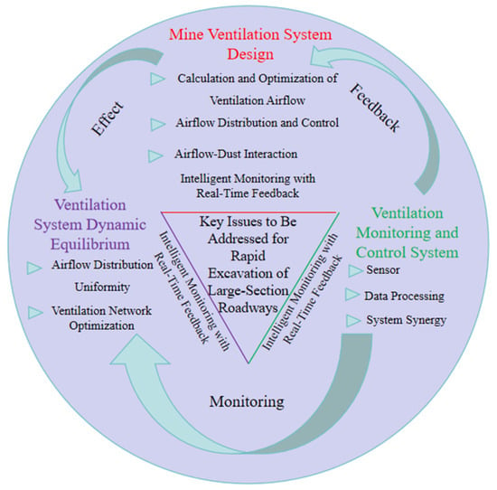
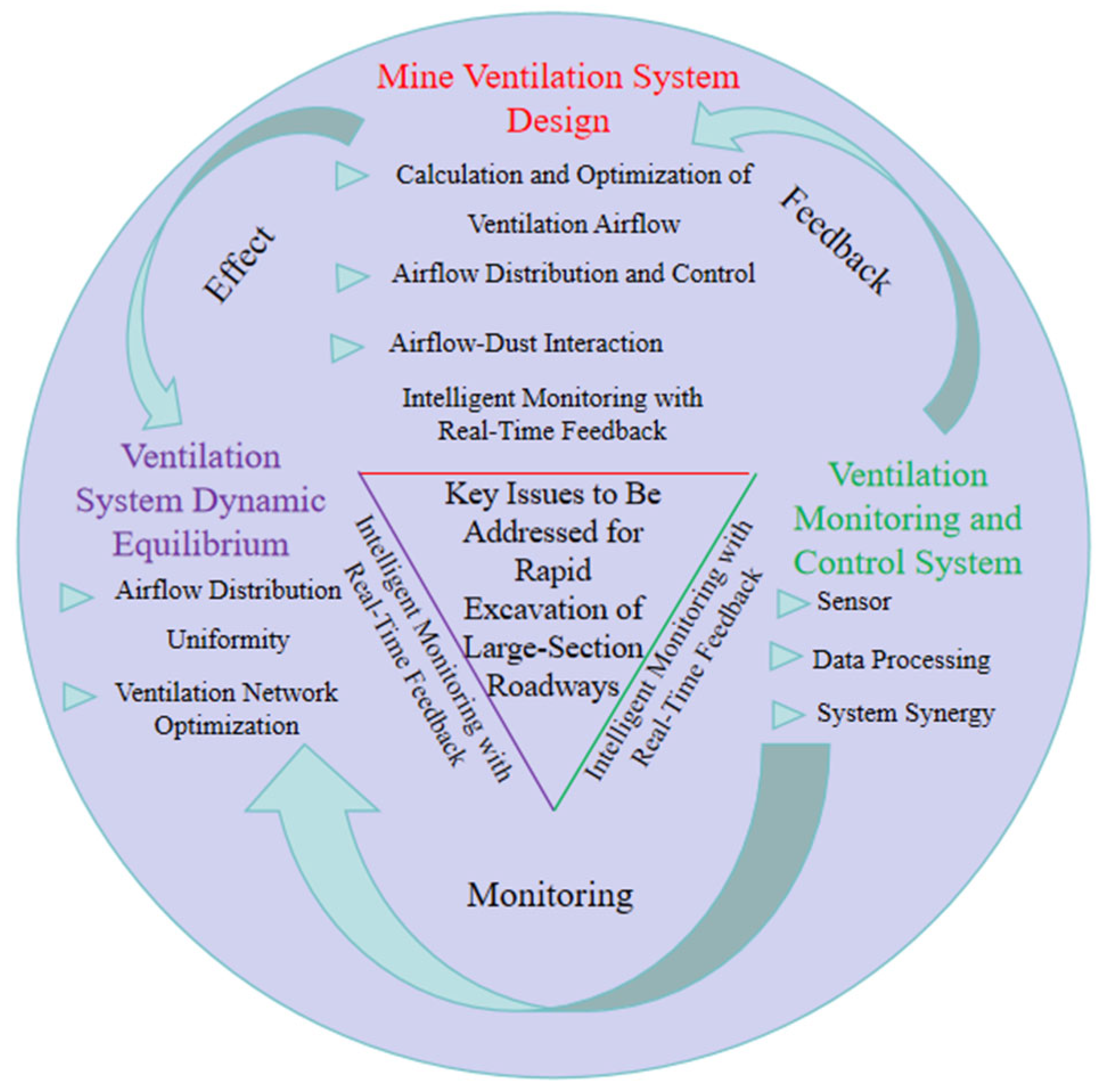
To achieve safe and rapid advancement during large-section roadway excavation, a technical approach following “ventilation system design → dynamic equilibrium of the ventilation system → intelligent monitoring, real-time feedback, and timely adjustment” is adopted to establish an adjustment pathway for the ventilation system that is adaptable to different geological conditions and large-section dimensions. The key issues to be addressed include design of the ventilation system; local and global adjustments of the ventilation system; variation patterns of roadway temperature, airflow rate, and CO and CO2 concentrations; and monitoring and control of the ventilation system. Ultimately, a rapid excavation ventilation system featuring “high efficiency, low energy consumption, safety and reliability” is established, as shown in Figure 1.
Figure 1.
Contents of the research on the ventilation system for rapid excavation of large-section roadways.
2.1. Design of Ventilation System for Rapid Excavation of Large-Section Roadways
Large-section roadways typically imply a larger working zone volume, which requires the ventilation system to provide sufficient airflow. Accurately calculating and optimizing ventilation airflow is a key issue. Due to the dynamic changes during roadway excavation, the airflow needs to be flexibly adjusted according to factors such as excavation speed, roadway dimensions, and the release rate of harmful gases [21].
In large-section roadways, the large cross-sectional area may lead to airflow disorder, accumulation of harmful gases, and insufficient oxygen concentration. Regulating airflow through ventilation facilities to eliminate zones with weak or stagnant airflow throughout the roadway becomes more difficult.
During roadway excavation, the interaction between airflow and substances such as coal dust and methane is highly complex. Particularly in the case of methane emission, preventing airflow-induced methane explosions is a major challenge in ventilation system design. Additionally, the settlement and dispersion of coal dust are influenced by airflow velocity, wind direction, roadway cross-section, and other factors, which must be comprehensively considered when designing the ventilation system.
2.2. Adjustment of the Ventilation System for Rapid Excavation of Large-Section Roadways
During large-section roadway excavation, local and global adjustments of the ventilation system are critical for ensuring operational safety and efficiency. First, the main issue in local ventilation adjustment lies in the uniformity and stability of airflow distribution. In large-section excavation, the significantly increased cross-sectional area of the roadway reduces airflow velocity, easily generating vortices and dead zones, which hinder the removal of harmful gases [22]. A rational layout scheme for local ventilation equipment is required to ensure that the airflow effectively covers the entire heading face. In addition, the power selection and airflow regulation of local ventilation equipment need to be dynamically adjusted according to excavation progress.
Second, the adjustment of the overall ventilation system involves the optimization and coordination of the mine ventilation network. Large-section excavation can alter the resistance distribution of the mine ventilation network, potentially causing imbalance in the ventilation system, leading to insufficient or excessive airflow in certain zones. By adjusting the operating parameters of the main fan or optimizing the layout of ventilation roadways, the dynamic equilibrium of the entire mine ventilation system can be achieved [23].
Furthermore, large-section excavation typically requires larger airflow volumes and higher air pressures, resulting in a significant increase in ventilation energy consumption. Under the premise of ensuring ventilation effectiveness, optimizing the operating parameters of ventilation equipment or introducing intelligent control technologies can reduce the energy consumption of the ventilation system, thereby further lowering production costs.
2.3. Ventilation Detection and Control System for Rapid Excavation of Large-Section Roadways
The environment of a large-section heading face exhibits high dynamics, strong interference, and multi-field coupling characteristics [24]. First, existing sensors have insufficient stability and anti-interference capability in extreme environments, which may lead to the accumulation of measurement errors in key parameters. Second, the spatiotemporal synchronization and fusion accuracy of geological information, environmental parameters, and equipment status are inadequate, making it difficult to construct a high-fidelity dynamic environmental model.
During large-section excavation, surrounding rock deformation, equipment pose changes, and ventilation parameter fluctuations are highly time-varying, requiring the feedback system to possess millisecond-level data processing and decision-making capabilities. However, current technologies face two major bottlenecks: (i) the real-time transmission and computational capacity of detection data are insufficient, making it difficult to perform feature extraction and anomaly identification under low-latency conditions; and (ii) the adaptability of dynamic regulation models is limited.
The ultimate goal of an intelligent monitoring system is to achieve dynamic equilibrium through the coordination of subsystems such as ventilation, support, and dust control. However, multi-system synergy entails risks of actuator response lag and action conflicts. Furthermore, delays in fan speed adjustment and limitations of control system commands may lead to overshoot or oscillation during the regulation process, affecting system stability [25]. How to establish a collaborative control framework that balances response speed and robustness still requires virtual–real interaction validation using digital twin technology.
3. Ventilation System Design for the “Excavation–Backfilling–Retention” Method
According to the technological characteristics of the integrated “excavation–backfilling–retention” mining process for inter-section coal pillars and gate roads, the roadway ventilation system is divided into four key stages, corresponding to the four main periods of the entire coal pillar excavation and mining process, namely the bypass excavation period, the period of excavation for the two gate roads, the working face construction period, and the inter-section coal pillar recovery period.
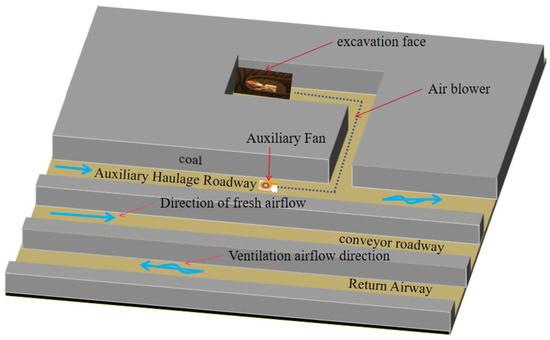
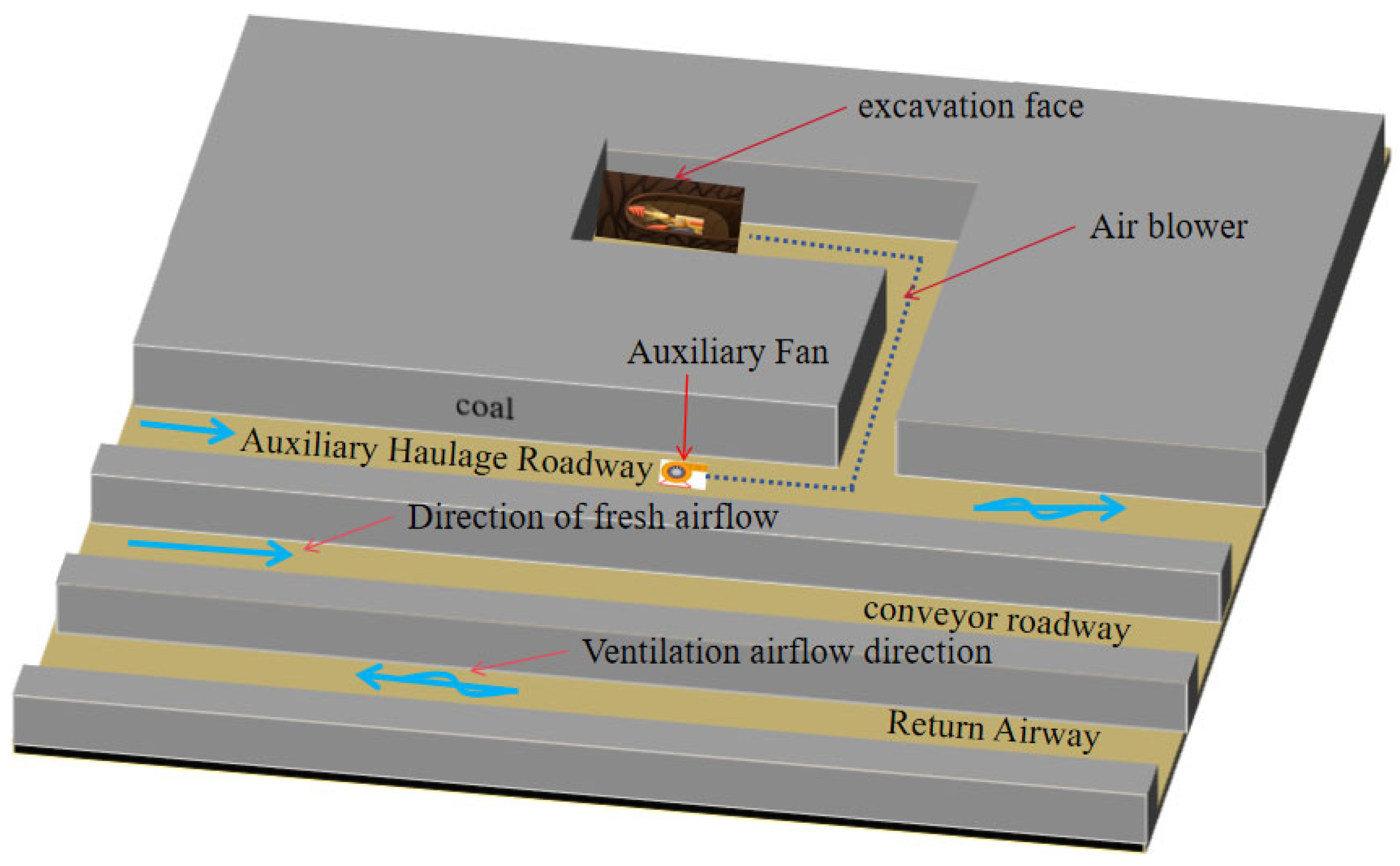
During the initial stage of inter-section coal pillar excavation, the following preparations are required. As shown in Figure 2, a bypass is driven along the pre-planned inter-section coal pillar side from the main auxiliary transport roadway. To ensure ventilation safety at the working face, an auxiliary fan is installed approximately 15 m before the bypass opening. Based on the airflow calculation described below, an FBDYN7.5/2 × 55 kW mine explosion-proof counter-rotating axial-flow auxiliary fan manufactured by Zhejiang Shuntong Electric Co., Ltd., Yueqing, Zhejiang, China was selected, together with a flexible rubber flame-retardant air duct manufactured by Hengshui Shenglong Rubber Products Co., Ltd., Hengshui, Hebei Province, China. (1000 mm diameter, 10 m per section). The duct joints adopt a double-rolled edge connection method and a dedicated duct connector to ensure sealing and connection reliability. The air duct is properly hung along the sidewall of the bypass to prevent contamination of the fresh airflow and maintain a good working environment. Fresh air from the main auxiliary transport roadway is delivered to the heading face via the auxiliary fan and air duct, while contaminated air returns through the bypass to the main auxiliary transport roadway and is eventually exhausted through the return airway.
Figure 2.
Ventilation design diagram for the bypass excavation period.
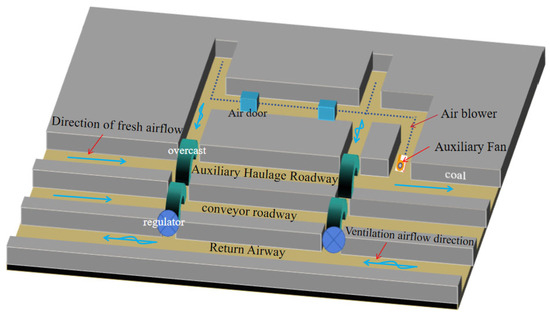
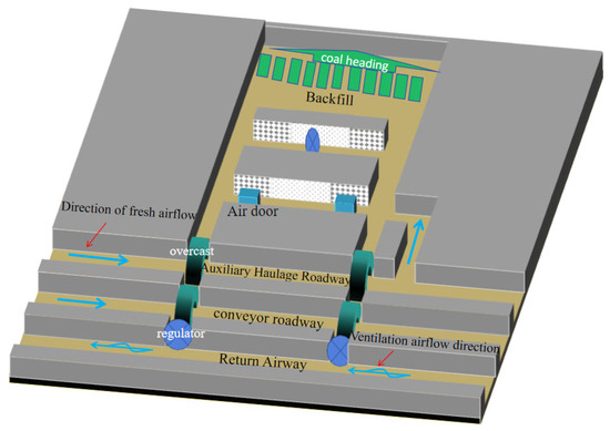
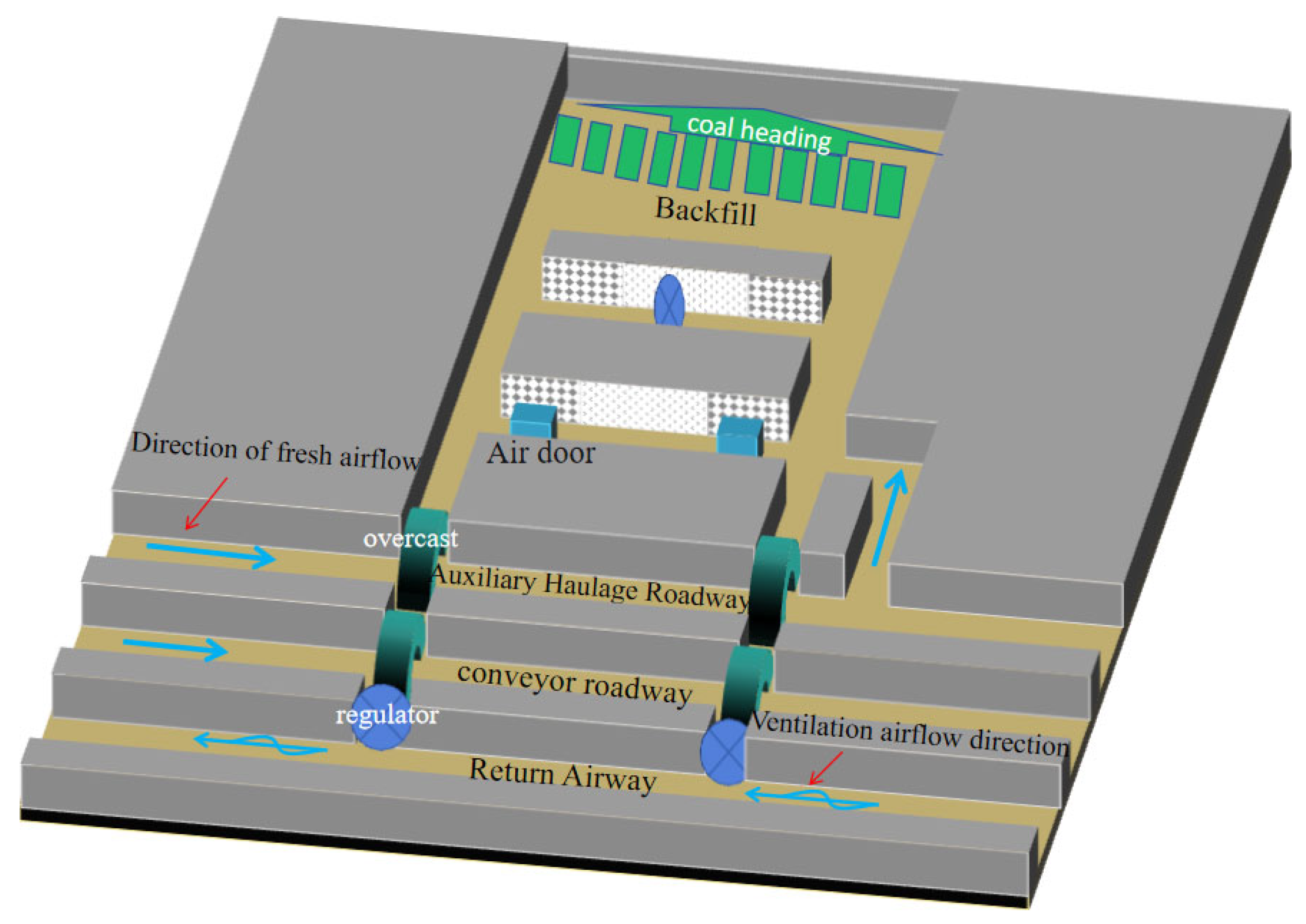
Since the integrated “excavation–backfilling–retention” technology for inter-section coal pillars is still in the exploratory stage, to ensure ventilation safety during excavation, the twin-roadway driving method is adopted for a certain distance. As shown in Figure 3, during the excavation period for the two gate roads, the gate roads are simultaneously driven along both sides of the pre-reserved inter-section coal pillar. To optimize air supply performance, the auxiliary fan is moved forward into the bypass, effectively shortening the air supply distance, thereby improving the ventilation conditions at the working face and ensuring operational safety. Air doors are installed at the connections between the bypass and the two gate roads to prevent cross-contamination of contaminated air from the two gate roads. Meanwhile, air bridges are constructed at the intersections of the main auxiliary transport roadway, the main belt transport roadway, and the gate roads, and a regulating vent is installed at the connection between the main belt transport roadway and the return airway to prevent backflow of contaminated air, ensuring the stability and reliability of the entire working face ventilation system. Fresh air is delivered from the main auxiliary transport roadway to the working face via the auxiliary fan and air duct, while contaminated air passes through the air bridges at the intersections of the gate roads with the main auxiliary transport and belt transport roadways, and then merges into the return airway through a one-way vent window to be exhausted.
Figure 3.
Ventilation design diagram for the excavation period for the two gate roads.
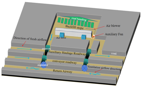
At this stage, the “excavation–backfilling–retention” working face has formed a full-air-pressure ventilation system. Because of the various instabilities present underground, and to ensure safety during actual construction, the auxiliary fan is not removed directly during the excavation period but is gradually shut down after testing whether the airflow volume under the full-air-pressure ventilation meets the requirements. Only when ventilation safety is ensured is the auxiliary fan removed. As shown in Figure 4, fresh airflow enters the “excavation–backfilling–retention” working face through the transport gate road. The contaminated air generated at the working face passes through the return gate road, then through the air bridges between the gate road and the main auxiliary transport roadway, and between the main auxiliary transport roadway and the main belt transport roadway. After being regulated by the ventilation window, it merges into the return airway and is exhausted.
Figure 4.
Ventilation design diagram for the inter-section coal pillar excavation period.
During the cyclic operation period, the large-section heading face establishes a stable full-air-pressure ventilation system. As shown in Figure 5, no auxiliary fan is installed. Only the ventilation windows and air bridges at the intersections of the two gate roads with the main auxiliary transport roadway and the main belt transport roadway are retained for airflow regulation. Similar to the excavation period, fresh air flows from the main auxiliary transport roadway through the bypass into the “excavation–backfilling–retention” working face, while contaminated air merges into the return airway through the return gate road. Considering that the backfill body needs to serve the ventilation of the subsequent fully mechanized longwall working face, connecting roadways are set at intervals of 75 m. In these connecting roadways, a “seal one out of three” ventilation arrangement is adopted (i.e., after installing three ventilation windows, a temporary air-stopping wall is constructed). This improves the effective utilization of system airflow and enhances the flexibility of ventilation regulation.
Figure 5.
Ventilation design diagram for the cyclic operation period.
The ventilation system for the “excavation–backfilling–retention” method adopts a combined ventilation technology integrating full-air-pressure and auxiliary fan ventilation. This is an efficient and safe ventilation technique, which utilizes the two parallel roadways left after backfilling to form an intake–return ventilation system. By leveraging the natural draft from full-air-pressure ventilation supplemented by auxiliary fan ventilation, it ensures an adequate supply of fresh air to the heading face. The full-air-pressure ventilation system uses connecting roadways between the parallel entries to regulate airflow, forming a stable airflow path and effectively reducing ventilation resistance. Meanwhile, the auxiliary fan is installed in the intake airway and moves forward continuously as excavation progresses, meeting the air demand at the heading face. This technical approach not only improves ventilation efficiency but also reduces the energy consumption and maintenance costs of ventilation equipment. Furthermore, the two roadways formed by the “excavation–backfilling–retention” method facilitate transportation and operations, thereby enhancing excavation speed and overall mine production efficiency. Therefore, the combined full-air-pressure and auxiliary fan ventilation technology offers significant advantages in large-section excavation operations.
3.1. Calculation of Airflow Demand for the Working Face
The actual required airflow Qjj at the working face shall be calculated separately based on the number of personnel, the CO2 emission rate, the gas emission rate, and the intake airflow of the auxiliary fan. The maximum of these values shall be selected and finally verified using the airflow corresponding to the minimum allowable wind speed at the working face.
(1) Calculated based on the maximum number of personnel per shift at the working face: the maximum number of personnel per shift is 45 persons, with an air requirement of 4 m3/min per person. Therefore, the required airflow at the working face Q1 = 45 × 4 = 180 m3/min.
(2) Calculated based on the maximum CO2 emission rate at the working face:
where Qjj is the required airflow at the working face, m3/min; Q1 is the absolute CO2 emission rate of the working face, m3/min, taken as 0.09; K1 is the ventilation coefficient for uneven CO2 emission at the working face, taken as 2.0.
Qjj = 100 × q × K = 100 × 0.09 × 2.0 = 18 m3/min
(3) Calculated based on the gas emission rate:
where Qch4 is the required airflow at the working face, m3/min; Q2 is the absolute gas emission rate of the working face, m3/min, taken as 0.17; K2 is the coefficient of non-uniform reserve air quantity, taken as 1.4.
Qch4 = 100 × Q2 × K2 = 23.8 m3/min
(4) Verification based on the minimum allowable wind speed:
where Qjj is the required airflow at the “excavation–backfilling–retention” working face, m3/min; S-cross-sectional area of the roadway, m2.
Qjj = 15S = 15 × 80 = 1200 m3/min
Since the three airflow values calculated based on the maximum number of personnel per shift, the maximum CO2 emission rate, and the gas (CH4) emission rate are all relatively small and differ significantly from the minimum air supply obtained by the minimum allowable wind speed verification, they cannot meet the requirements for diluting heat, coal dust, and potential CO accumulation under large-section, long-distance excavation conditions. Therefore, to ensure ventilation safety during the excavation of large-section roadways, 1200 m3/min is selected as the design required airflow for the working face.
3.2. Calculation of the Air Resistance of the Air Duct at the Working Face
The air resistance of the air duct consists of frictional resistance and local resistance. The local resistance includes the local resistance at the duct joints and the local resistance at the duct bends [26]. The heading face of the inter-section coal pillar is a straight roadway excavation, and the local resistance caused by the gentle transition of the air duct at bends can be neglected. Therefore, the air resistance of the air duct is composed of frictional resistance and the local resistance at the duct joints.
where R is the total air resistance of the air duct, N·s2/m8; R1 is the local air resistance of the air duct, N·s2/m8; R2 is the local air resistance at the air duct joint, N·s2/m8; α is the frictional resistance coefficient of the air duct, N·s2/m8; L is the length of the air duct, m; U is the wetted perimeter of the air duct, m; S is the cross-sectional area of the air duct, m2; n is the number of joints of the air duct; ε is the local resistance coefficient of the air duct joint; ρ is the air density, kg/m3.
For the inter-section coal pillar heading face, the length L of the air duct is 2000 m. A flexible air duct with a diameter of 1000 mm and a segment length of 10 m is selected. S = 0.785 m2, U = 3.14 m, n = 200, α = 28 × 10−4 N·s2/m8 [27], ε = 0.035 [28], ρ = 1.2 kg/m3.
Substituting into Equation (1) yields R = 44.53 N·s2/m8.
3.3. Calculation of the Air Leakage Rate of the Air Duct at the Working Face
Table 1.
Air leakage rate per 100 m of flexible air duct.
The air duct joint adopts a double rolled edge butt joint; therefore, the value is taken as η100 = 0.6%. From Equation (2), we obtain η = 12%.
3.4. Calculation of Other Required Airflow for the Working Face
(1) Airflow rate at the inlet of the air duct of the auxiliary fan:
The calculation yields Qr = 681 m3/min.
(2) Calculation of airflow rate in the air duct at the working face:
The calculation yields Q = 639 m3/min.
(3) Ventilation resistance of the air duct at the working face h = RQ2.
The calculation yields h = 5426 Pa.
3.5. Calculation of Total Pressure of the Auxiliary Fan at the Working Face
The total pressure of the auxiliary fan is used to overcome the ventilation resistance of the air duct and the outlet kinetic energy loss.
where H is the total pressure of the auxiliary fan; vc is the air velocity at the air duct outlet; hvc is the outlet kinetic energy loss.
The calculation yields H = 5484 Pa.
3.6. Selection of the Auxiliary Fan for the Working Face
Based on the required operating point of the auxiliary fan (airflow rate of 681 m3/min and air pressure of 5484 Pa), the FBDYN07.5 (2 × 55 kW) auxiliary fan was selected within the reasonable range of the characteristic curves of various auxiliary fans. Its airflow rate ranges from 680 to 980 m3/min, and its total pressure ranges from 1400 to 6500 Pa. This fan meets the airflow requirements during the excavation of the inter-section coal pillar and complies with relevant regulations.
4. Numerical Simulation Study of Large-Section Excavation
4.1. Model Construction
To verify the feasibility of the integrated ventilation safety assurance technology for inter-section coal pillar excavation and mining, a heading face in a certain mine in northern Shaanxi using the integrated “excavation–backfilling–retention” mining technology for inter-section coal pillars and gate roads was first taken as an example and simulated using COMSOL software. The coal seam in this mine has a thickness of 5.8–10.2 m, with an average thickness of 8 m, a burial depth of 260 m, and a dip angle of less than 1°. It is classified as a low-gas mine, and the coal seam belongs to Class I (easily spontaneous combustion), with a spontaneous combustion period of approximately 45–60 days.
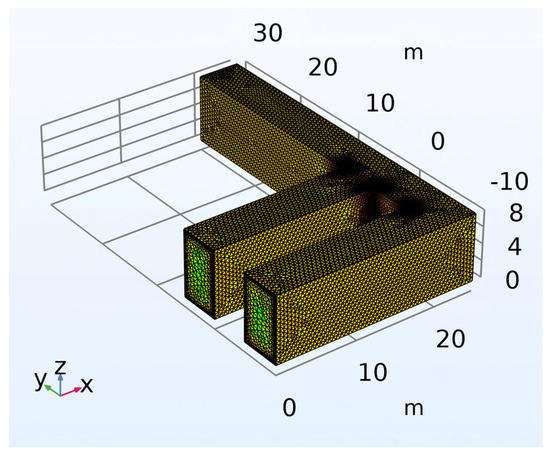
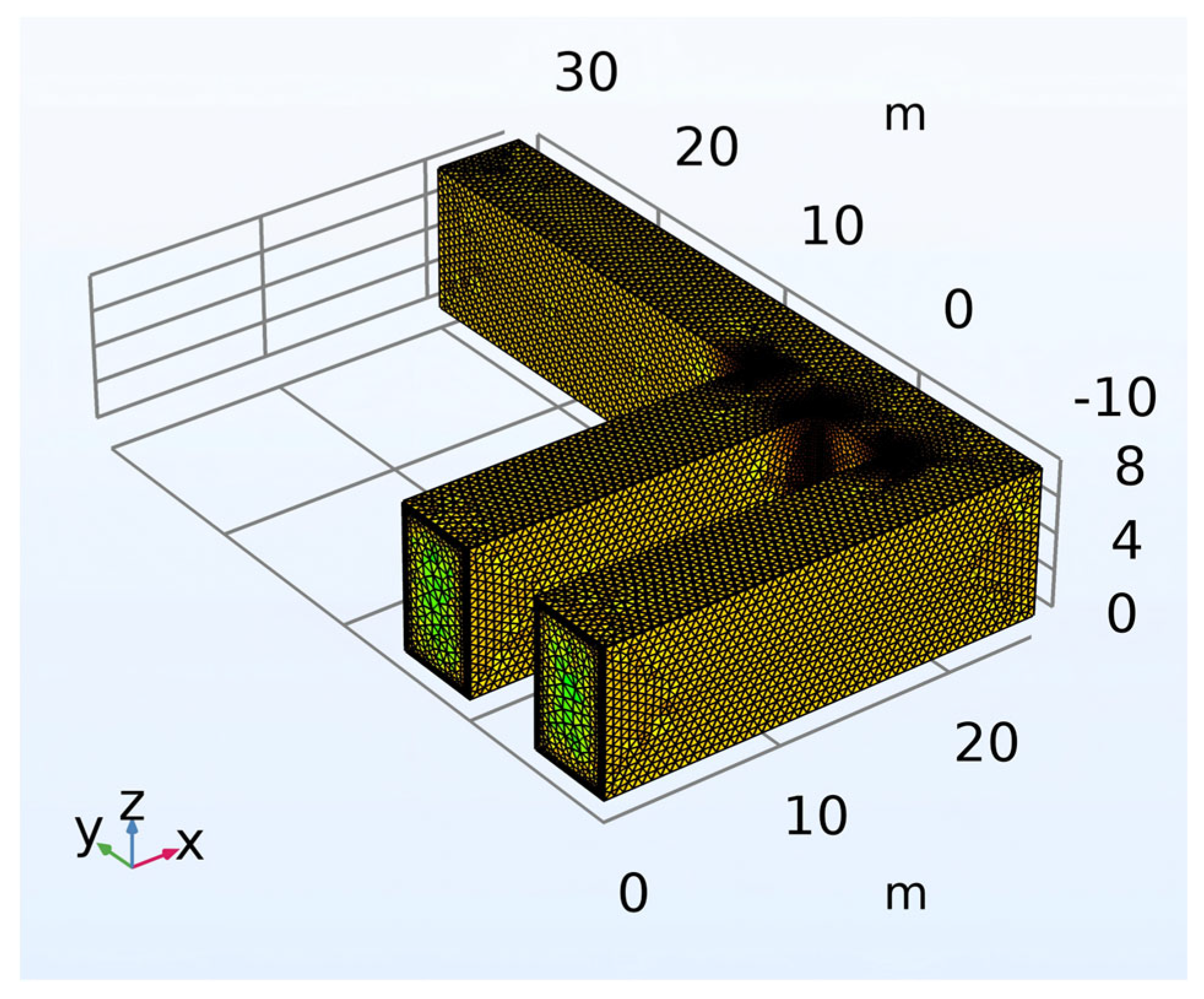
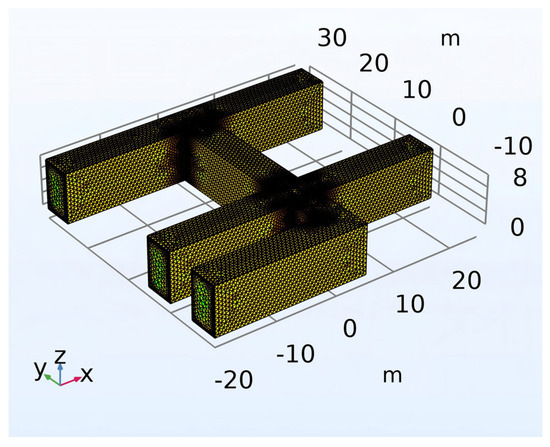
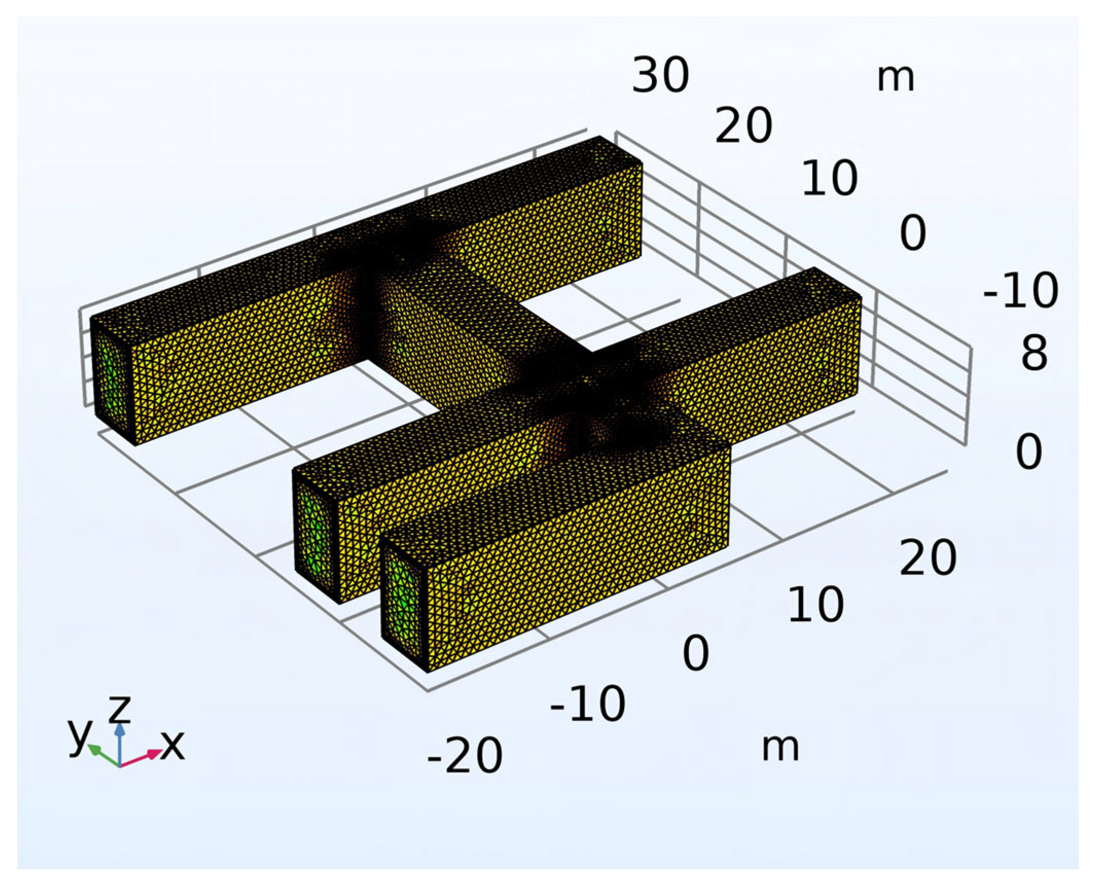
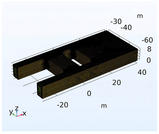
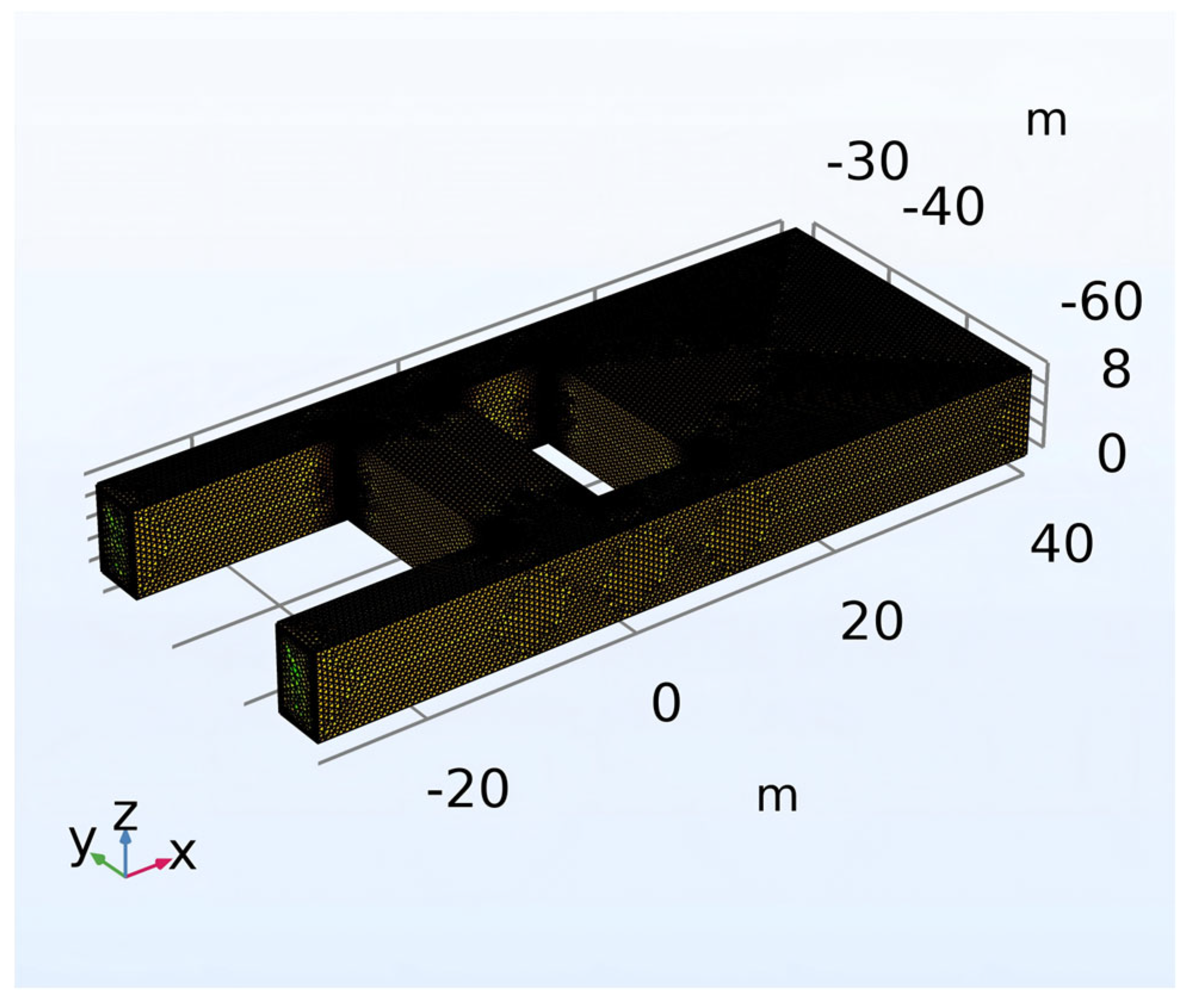
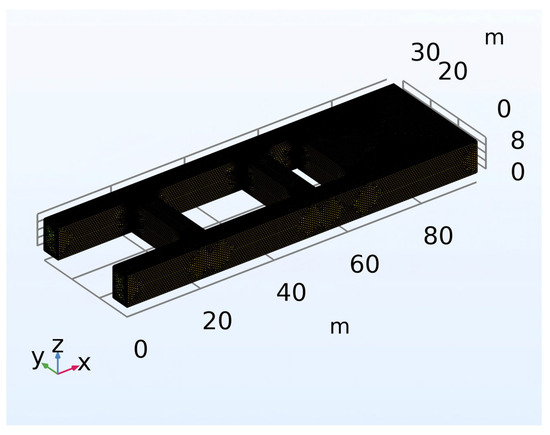
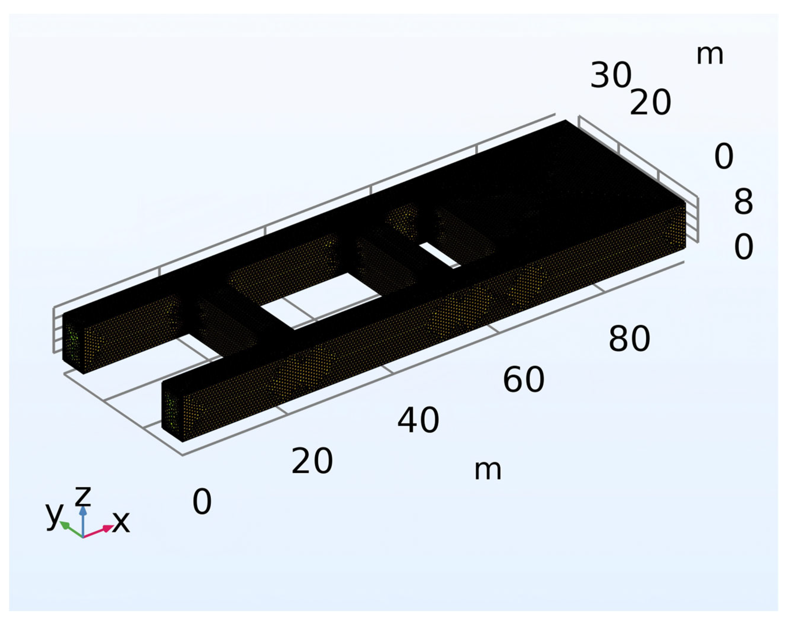
The simulation domain is a three-dimensional region of 60 m × 30 m × 8 m. The X-axis direction corresponds to the direction from the large-section heading face toward the retained gob-side entry, the Y-axis represents the length of the large-section heading face, and the Z-axis is the vertical direction. A transient simulation was performed with a total time of 7 days and a time step of 0.5 day. The tolerance was chosen as “controlled by physics”, i.e., the absolute tolerance is automatically scaled according to the typical magnitudes of the field variables. The mesh was generated based on the physics fields. The three-dimensional model and mesh divisions are shown in Figure 6, Figure 7, Figure 8 and Figure 9.
Figure 6.
Mesh generation during the bypass excavation period.
Figure 7.
Mesh generation during the excavation period for the two gate roads.
Figure 8.
Mesh generation during the inter-section coal pillar excavation period.
Figure 9.
Mesh generation during the cyclic operation period.
4.1.1. Boundary Conditions and Governing Equations for Free and Porous Media Flow
(1) Boundary conditions
For the flow equations, the inlet boundary is set as mass flow, with the type selected as mass flow rate; the outlet boundary is set as pressure; and all solid walls are assigned no-slip boundary conditions.
(2) Governing equations
The gas and porous media flow in the model is governed by the law of mass conservation and the Reynolds-averaged Navier–Stokes (RANS) equations combined with the standard k–ϵ turbulence model. Under three-dimensional transient conditions, the governing equations for the free and porous media flow are as follows:
where ρ—fluid density, kg/m3; u—velocity vector, m/s; t—time, s; p—pressure (static pressure), Pa; I—unit tensor; K—viscous stress tensor, Pa; F—volume force vector, N/m3; μ—molecular dynamic viscosity, Pa·s; μT—turbulent viscosity, Pa·s; k—turbulent kinetic energy, m2/s2; ϵ—turbulence dissipation rate, 1/s; σk—turbulent Prandtl number for the k equation, taken as 1.0; σϵ—turbulent Prandtl number for the ϵ equation, taken as 1.3; Cϵ1—constant for the production term in the ϵ equation, taken as 1.44; Cϵ2—constant for the dissipation term in the ϵ equation, taken as 1.92; ∇—gradient operator; ∇⋅(·)—divergence operator of a tensor; ∇u—velocity gradient tensor, 1/s; (∇u)T—transpose of the velocity gradient tensor, 1/s; ∇⋅u—divergence of the velocity.
4.1.2. Boundary Conditions and Governing Equations for Heat Transfer in Porous Media
(1) Boundary conditions
In the heat transfer field calculation, all walls except the gas inlet and outlet are set as thermal insulators. The bypass roadway and the intake and return airways are set as fluid domains, while the two heading faces are set as heat sources. The initial temperature of the entire computational domain is set to 293.15 K (20 °C).
(2) Governing equations
In the thermal–fluid coupling process, the heat mainly comes from the oxidation heat of coal and oxygen. Based on the law of energy conservation and Fourier’s law of heat conduction, the governing equation for three-dimensional transient heat transfer in porous media is as follows:
where ρ—the density of the fluid, kg/m3; Cp—the specific isobaric heat capacity of the fluid, J/(kg·K); T—the temperature, K; t—the time, s; u—the velocity vector, m/s; ∇T—the temperature gradient, K/m; q—the heat flux, W/m2; Q—the volumetric heat source, W/m3; Qvd—the viscous dissipation term, W/m3; k—the thermal conductivity of the fluid, W/(m·K); ∇T—the temperature gradient, K/m. keff—effective thermal conductivity of porous media, W/(m·K); (ρCp)eff—effective volumetric heat capacity of porous media J/(m3·K).
4.1.3. Boundary Conditions and Governing Equations for Transport of Diluted Species in Porous Media
(1) Boundary conditions
In the transport of diluted species in porous media, the boundary type at the inlet is selected as Danckwerts. The transport of components in the porous medium includes both molecular diffusion and convection mechanisms, with the convective velocity provided by the free and porous media flow interface. The walls are set as no-flux.
(2) Governing equations
In the transport of diluted species in porous media, the CO content is almost entirely released from the low-temperature oxidation of coal [29,30,31], and its transport follows the law of mass conservation and Fick’s law of diffusion.
where εp—the porosity, dimensionless; ci—the concentration of component i in the pore fluid, kg/m3; t—the time, s; ρ—the density of the solid skeleton, kg/m3; cp,j—the density of component j in the solid phase, kg/m3; ∇⋅ji—the divergence of the diffusive flux ji of component i, kg/(m3·s); u—the Darcy velocity of the fluid, m/s; ∇ci—the concentration gradient of component i, kg/m4; Ri—the chemical reaction source term, kg/(m3·s); Si—other external source term, kg/(m3·s); Ji—the diffusive flux vector of component i, kg/(m2·s); De,i—the effective diffusion coefficient of component i in porous media, m2/s; ∇ci—the concentration gradient, kg/m4.
4.1.4. Mesh Independence Verification
The model adopted three mesh schemes with different element densities (Table 2), namely Scheme A, Scheme B, and Scheme C. Grid independence tests were carried out for these three schemes. Under the cyclic operation condition, after three days of operation, the characteristic points on the pore wall at the locations of T_max, O2_min, and CO_max were taken to compare the relative errors among the three schemes. Relative error calculation formula:
where Vi is the calculated value under the current mesh; Vi+1 is the calculated value under the next finer mesh.
Table 2.
Analysis of feature point temperatures and relative errors under different grid densities.
As can be seen from the calculation results in Table 2, with the increase in the number of mesh cells, the characteristic parameters T_max, O2_min, and CO_max gradually tend to stabilize. The calculated temperature difference between the conventional meshing strategy adopted in Scheme B and the refined meshing strategy adopted in Scheme C is only 0.07 °C, the CO concentration difference is merely 0.0000006, and the O2 concentration difference is only 0.0024. The maximum relative error between the two schemes is as low as 0.42%, which is far below the allowable error threshold for engineering numerical simulation. The mesh size at the key nodes ranges from 0.005 m to 0.1 m. Under a wind speed of 0.3 m/s, a roadway cross-sectional area of 80 m2, and a wall roughness of 0.05 with the k–ε turbulence model, the calculated y+ values fall within the range of 6.5 to 125, which lies within the applicable range of the k–ε wall function. In order to balance the accuracy of large-scale, long-duration transient calculations with the corresponding simulation time cost, all subsequent multi-physics coupled simulations in this study adopt the meshing strategy of Scheme B.
4.2. Temperature Variation in the Large-Section Excavated Retention Entry Zone
The temperature variation in the large-section excavation and retained gob-side entry area is an important indicator for ensuring personnel safety, normal operation of equipment, and disaster prevention. Coal in goaf or fractured zones can accumulate heat due to oxidation, and in these areas, residual coal easily builds up temperature, leading to spontaneous combustion, and could even trigger a gas explosion [32]. In the areas prone to spontaneous combustion, such as the two ends of the working face and the periphery of the backfill body, temperature monitoring should be carried out, and measures such as grouting and nitrogen injection should be taken in advance to prevent spontaneous combustion.
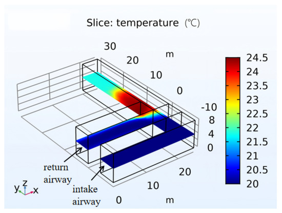
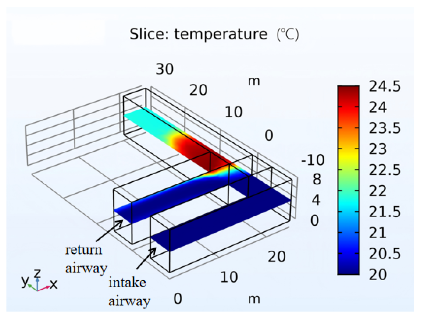
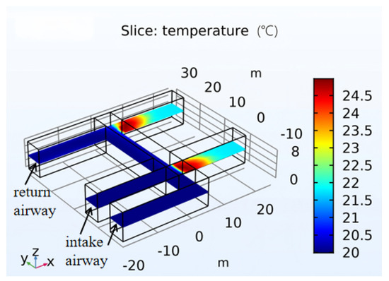
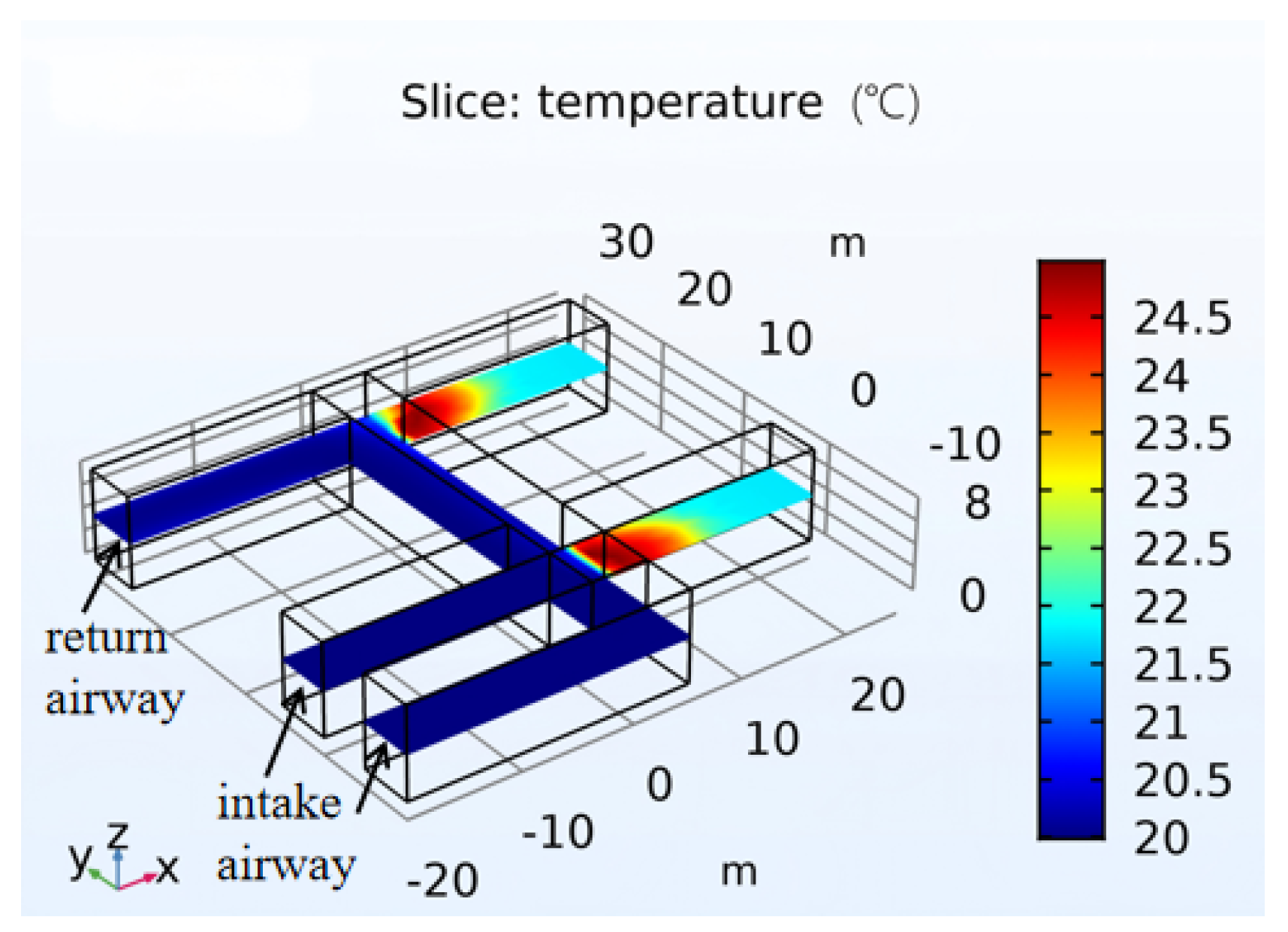
During the bypass excavation period, as shown in Figure 10, the temperatures in the bypass and the intake gate road are relatively low, approximately 21 °C. The highest temperature zone, not exceeding 24.5 °C, occurs at the junction between the bypass and the connecting roadway. From this junction toward the heading face, the temperature gradually decreases due to the reduced degree of coal oxidation resulting from the decrease in oxygen concentration. Overall, during the bypass excavation period, the roadway temperature is controlled between 20 °C and 24.5 °C, which complies with the requirement of not exceeding 26 °C stipulated in the Coal Mine Safety Regulations.
Figure 10.
Roadway temperature distribution during the bypass excavation period.
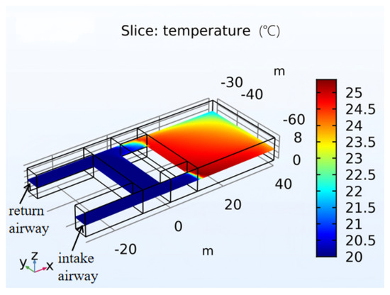
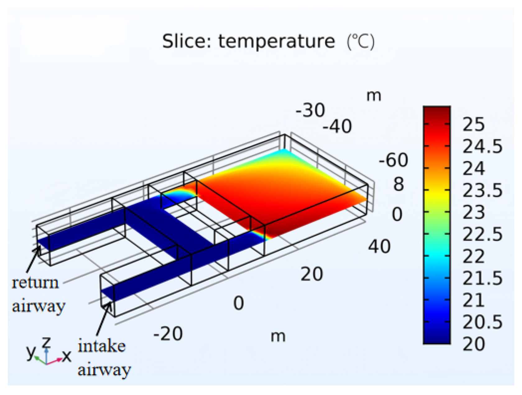
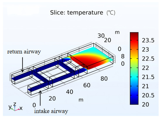
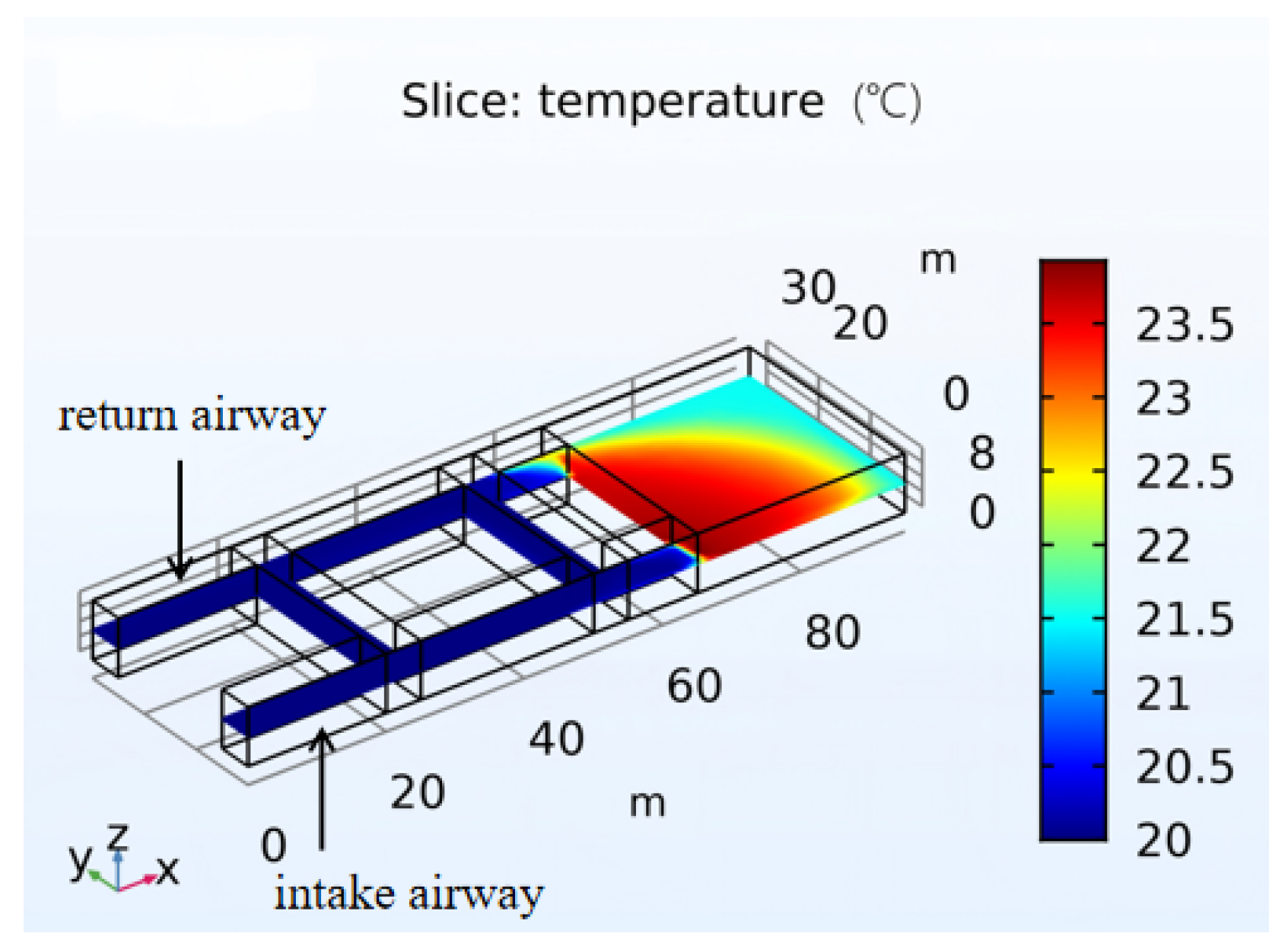
During the excavation period for the two gate roads, there is a distinct temperature distribution difference within the roadways, as shown in Figure 11. The areas shown in red, yellow, and other darker colors have relatively higher temperatures ranging from 23 °C to 25 °C, while the areas in blue and other lighter colors have relatively lower temperatures ranging from 20 °C to 23 °C. During the working face construction period, the highest roadway temperature occurs at the roadway entrance. Compared with the bypass excavation period, the increased ventilation distance of the excavated roadway during the excavation period for the two gate roads leads to a reduction in airflow at the roadway entrance, and therefore the temperature at this location rises to a certain extent.
Figure 11.
Roadway temperature distribution during the excavation period for the two gate roads.
During the inter-section coal pillar excavation period, the full-air-pressure ventilation system is established throughout the excavated roadway, forming a stable airflow path that effectively reduces ventilation resistance and ensures sufficient air supply to the roadway. As shown in Figure 12, the “three zones” are clearly delineated in the retention entry. At the intake gate road entrance, although oxygen is abundant, the large intake airflow prevents heat accumulation, thus forming a heat dissipation zone with temperatures ranging from 21.5 °C to 23.5 °C. In the middle zone, due to the short air supply distance and moderate oxygen concentration, the oxidation reaction can be sustained without excessive airflow removing the heat, thereby forming an oxidation heating zone with temperatures ranging from 24 °C to 25.5 °C. As the air supply distance increases, the oxygen concentration in the retention entry gradually decreases. When the oxygen concentration falls below the lower-limit oxygen concentration, the heat released by coal oxidation is insufficient to raise the temperature, leading to the formation of a self-extinguishing (inert) zone with temperatures ranging from 22.5 °C to 23.5 °C.
Figure 12.
Temperature distribution during the inter-section coal pillar excavation period.
During the cyclic operation period, the temperature variation patterns in the roadway and the retention entry are almost the same as those during the inter-section coal pillar excavation period, but with differences due to the longer air supply distance. As shown in Figure 13, the “three zones” in the retention entry are similar to those in the inter-section coal pillar excavation period. However, because of the increased ventilation distance, the air leakage loss increases, resulting in a reduced air supply, and the range of the self-extinguishing zone becomes significantly larger. The extent of the heat dissipation zone in the retention entry differs between the intake side and the return side. This is because the pressure on the intake side is higher, allowing high-pressure airflow to penetrate deeper, while the pressure on the return side is lower, causing the airflow in the retention entry to flow toward the return side. Consequently, the heat dissipation zone on the intake side is larger than that on the return side.
Figure 13.
Temperature distribution during the cyclic operation period.
4.3. Gas Variation Pattern in the Large-Section Excavated Retention Entry Zone
The O2 concentration and CO concentration in the roadway are both key parameters reflecting the coal spontaneous combustion process and critical factors determining the production safety of the working face [33,34]. Therefore, understanding the variation patterns of key gases in the roadway is essential for studying the ventilation safety issues of integrated excavation and mining of inter-section coal pillars.
4.3.1. Variation Pattern of O2 Concentration in the Roadway
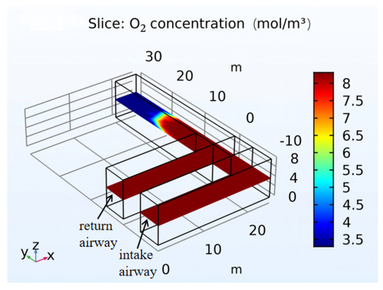
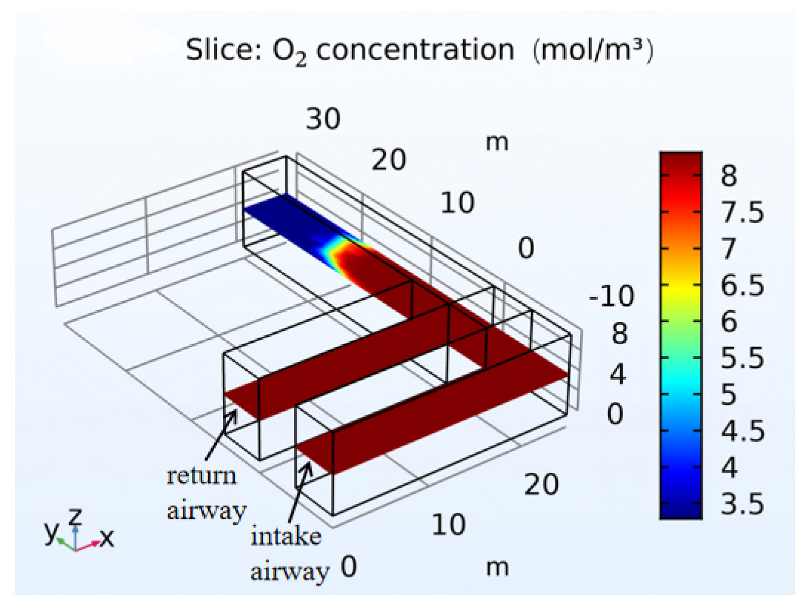
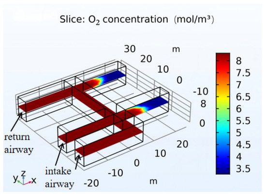
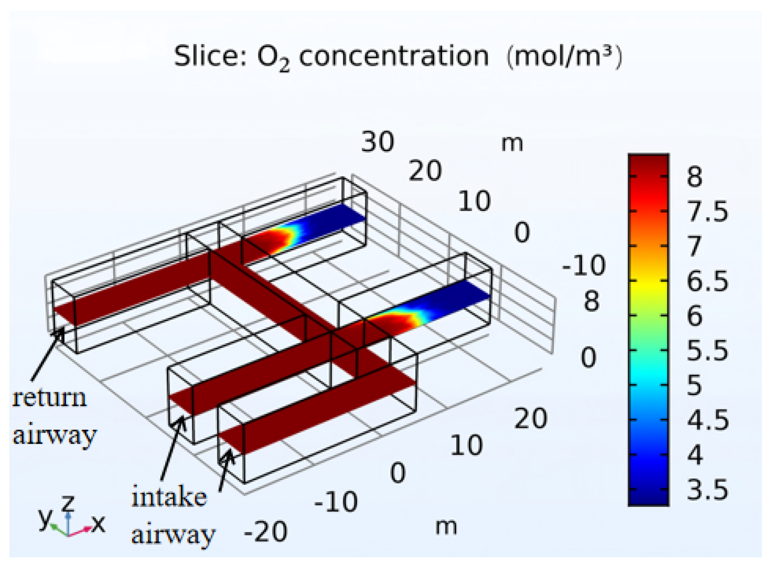
During the bypass excavation period, as shown in Figure 14, the oxygen concentration in the bypass and the intake airway is sufficient, reaching above 20%, which complies with the 20% requirement stipulated in the Coal Mine Safety Regulations and meets the oxygen supply demand during this period. However, after the connecting roadway is excavated beyond 20 m, the increased air supply distance leads to a reduction in airflow, making the oxygen concentration clearly insufficient to support the oxygen supply during excavation. At this point, the auxiliary fan should be moved to the bypass entrance to ensure normal working conditions.
Figure 14.
O2 concentration distribution in the roadway during the bypass excavation period.
During the excavation period for the two gate roads, the connecting roadway links the intake airway and the return airway, forming full-air-pressure ventilation. As shown in Figure 15, the oxygen concentrations in the bypass, the connecting roadway, the intake airway, and the return airway are sufficient, reaching above 20%. However, the effective oxygen supply distance in the two gate roads is only 20 m, which is far from meeting the oxygen demand for excavation work. Placing the auxiliary fan at the bypass entrance is clearly insufficient to support the excavation of the two gate roads. Therefore, when 10 m of the two gate roads are excavated, the auxiliary fan should be moved forward to the entrance of the gate road on the intake airway side to ensure normal excavation operations.
Figure 15.
O2 concentration distribution in the roadway during the excavation period for the two gate roads.
During the inter-section coal pillar excavation period, full air pressure ventilation is established between the roadway and the working face. As shown in Figure 16, the oxygen concentration in the roadway is sufficient, reaching above 20%, which complies with the requirements of the Coal Mine Safety Regulations and meets the oxygen supply demand of the working face during inter-section coal pillar excavation.
Figure 16.
O2 concentration distribution in the roadway during the inter-section coal pillar excavation period.
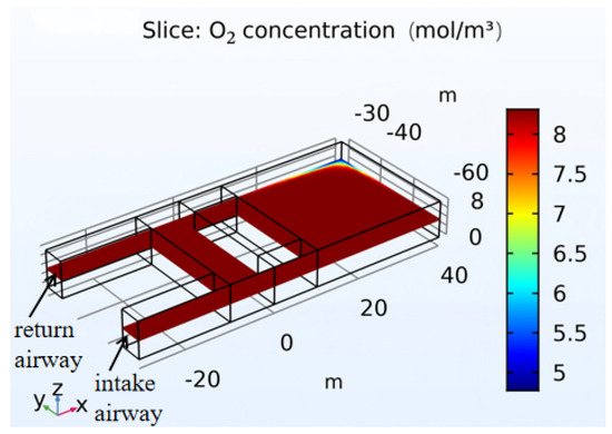
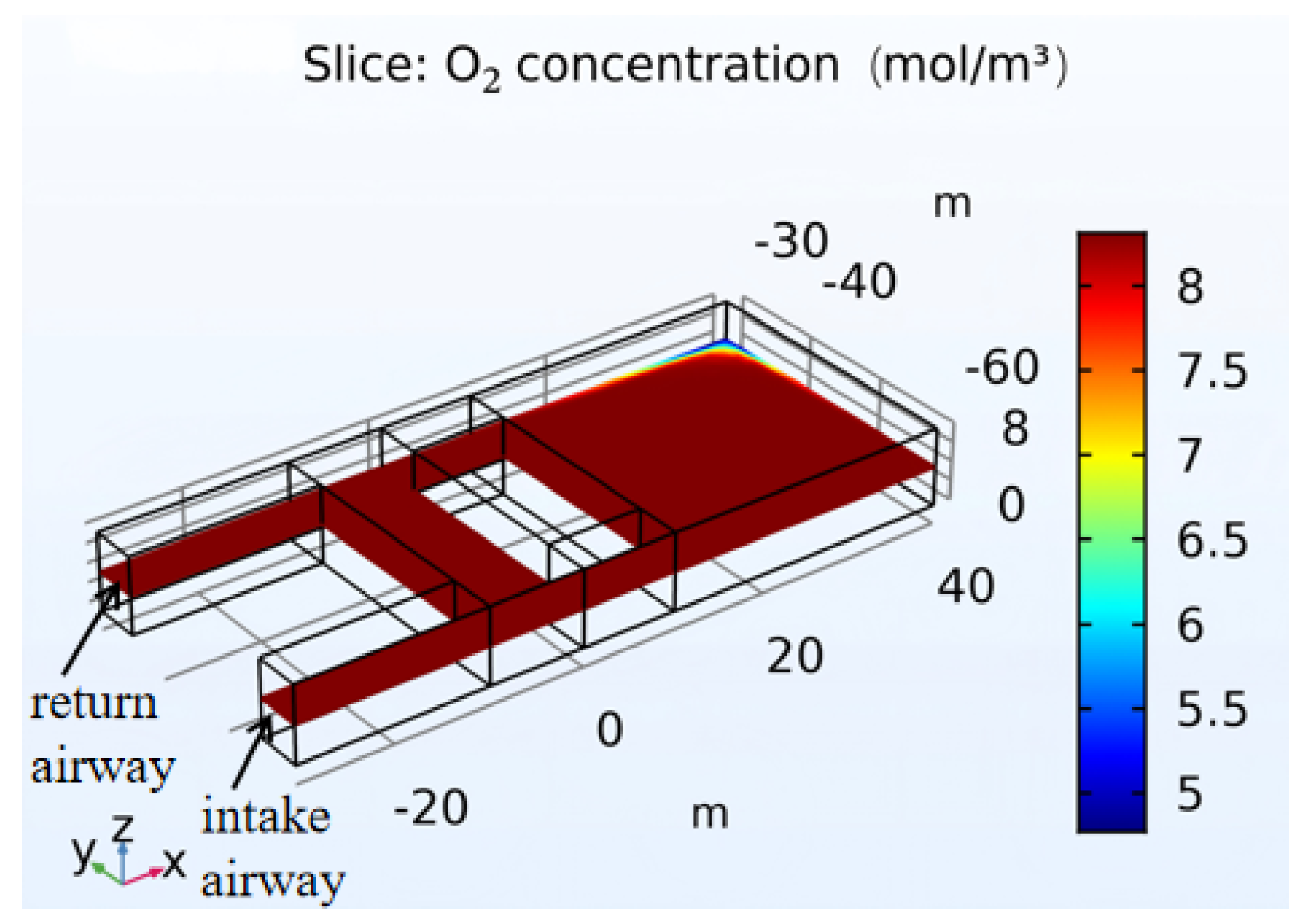
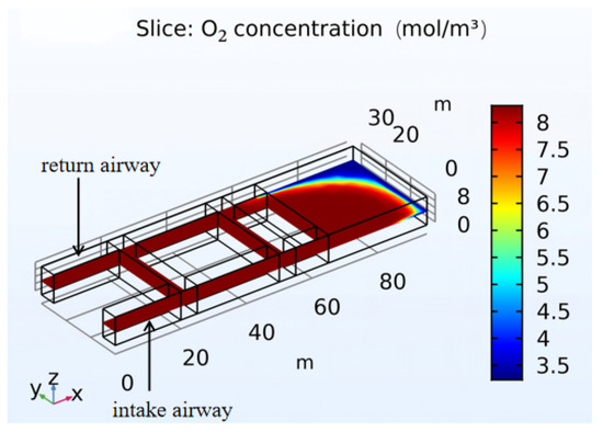
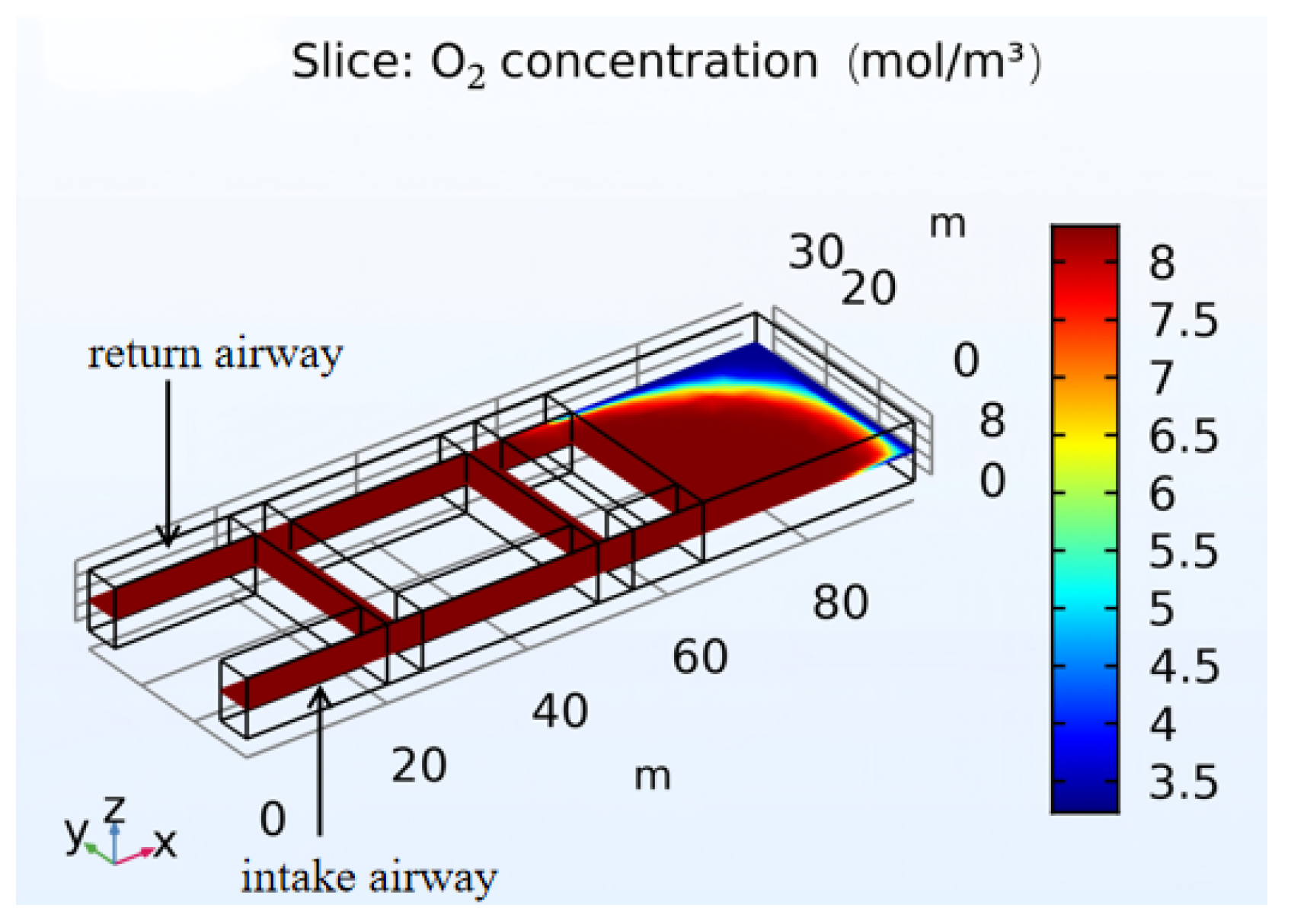
During the cyclic operation period, as shown in Figure 17, the increased air supply distance leads to higher air resistance and some airflow loss. In the return gate road side corner of the working face, there is a local area with insufficient oxygen concentration. However, the oxygen concentration within the entire retention entry length of 30 m is still sufficient to ensure the oxygen supply for both the construction of the filling grid and the excavation work. In subsequent operations, special attention should be paid to oxygen concentration monitoring in this area.
Figure 17.
O2 concentration distribution in the roadway during the cyclic operation period.
4.3.2. Variation Law of CO Concentration in Roadway
During the excavation period of the bypass roadway, as shown in Figure 18, the auxiliary fan is positioned at a relatively short ventilation distance, resulting in low airflow resistance. The sufficient air supply keeps the CO concentration in both the intake airway and the bypass roadway at a relatively low level of approximately 2.45 and 14.7 ppm, which is below the limit of 24 ppm stipulated by the Coal Mine Safety Regulations. Thus, the construction safety and environmental requirements for the bypass roadway excavation are satisfied. At a distance of 20 m into the connection roadway, gas retention occurs, and the CO concentration rises significantly, revealing the coupling mechanism between gas migration inside the coal pillar and the ventilation effect. Based on the simulation results, it is recommended to move the auxiliary fan forward to the entrance of the bypass roadway during subsequent excavation of the connection roadway.
Figure 18.
CO concentration distribution in the roadway during the bypass roadway excavation period.
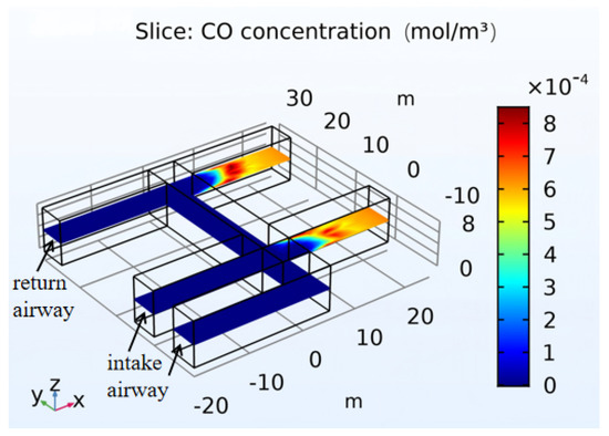
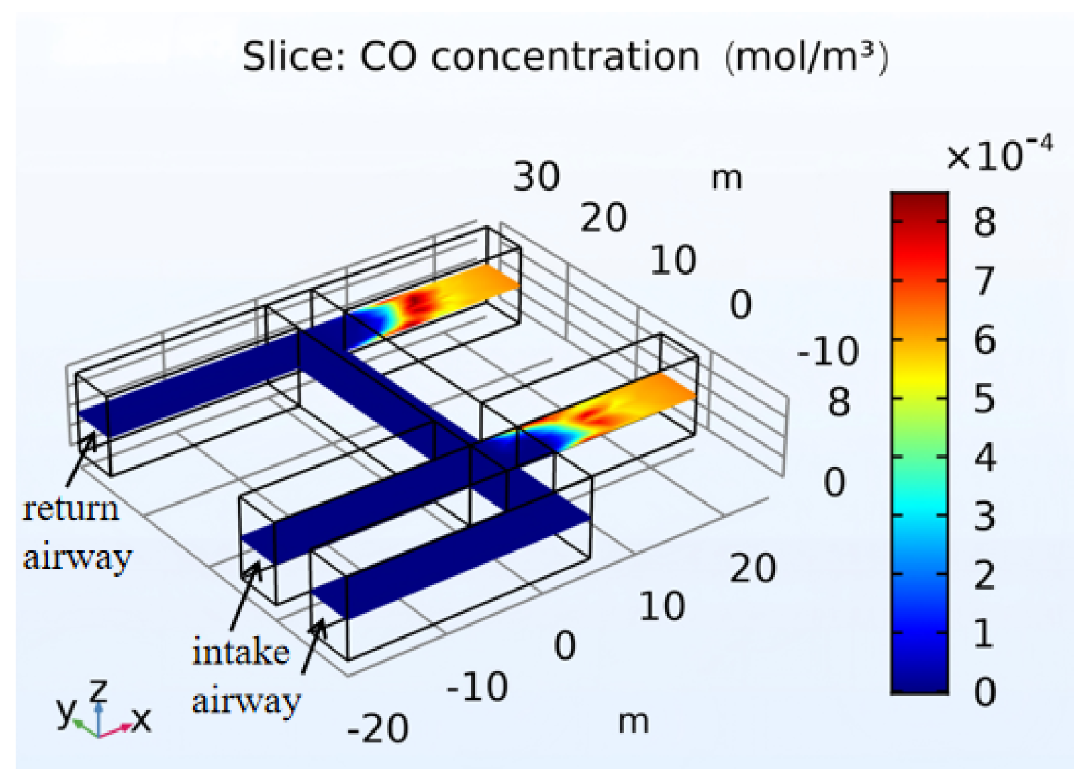
During the excavation period for both gate roads, as shown in Figure 19, due to the connection of the connecting roadway, the bypass roadway forms a full-pressure ventilation system with the intake airway and the return airway, establishing a stable airflow path. This effectively reduces the airflow resistance, and the CO concentration in the roadways remains at 2.45 and 14.7 ppm, which is below the limit of 24 ppm required by the Coal Mine Safety Regulations. However, in the area beyond 15 m in the two gate roads, the CO concentration increases significantly, ranging between 19.6 and 22 ppm, and approaches the safety limit. Since the CO concentration will gradually increase with working time, in order to ensure ventilation safety, the auxiliary fan should be moved forward to the intake-side gate road entrance.
Figure 19.
CO concentration distribution in the roadways during the excavation period for both gate roads.
During the excavation period for the inter-section coal pillar, as shown in Figure 20, the roadway forms a full-pressure ventilation system with the “excavation–backfilling–retention” working face. The CO concentration in the roadway ranges between 2.45 and 14.7 ppm, and the dilution effect of the airflow on CO is relatively uniform, indicating that the full-pressure ventilation method can effectively control CO accumulation. However, the CO concentration at the corner on the return airway side of the coal pillar is relatively high. Therefore, in actual operations, special attention should be paid to monitoring the CO concentration at this location.
Figure 20.
CO concentration distribution in the roadway during the excavation period for the inter-section coal pillar.
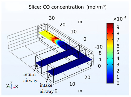
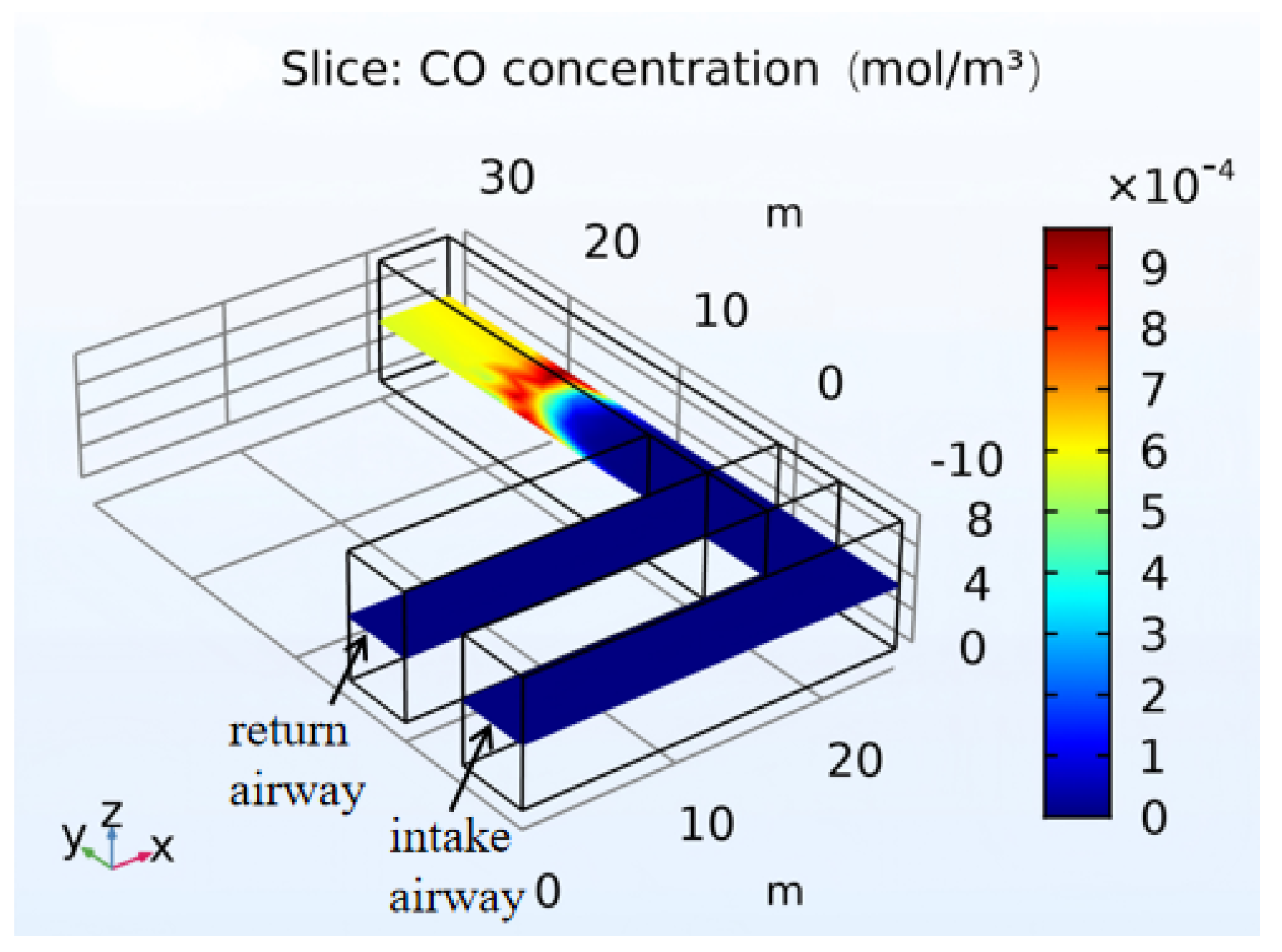
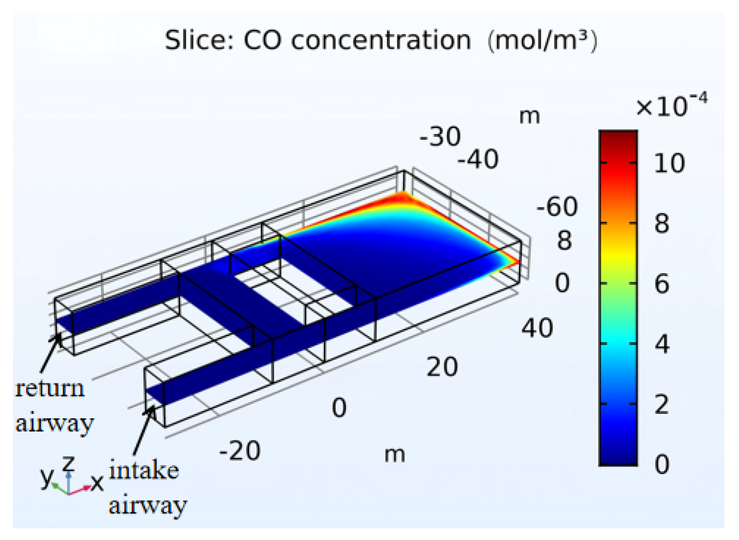
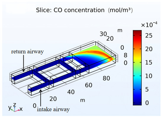
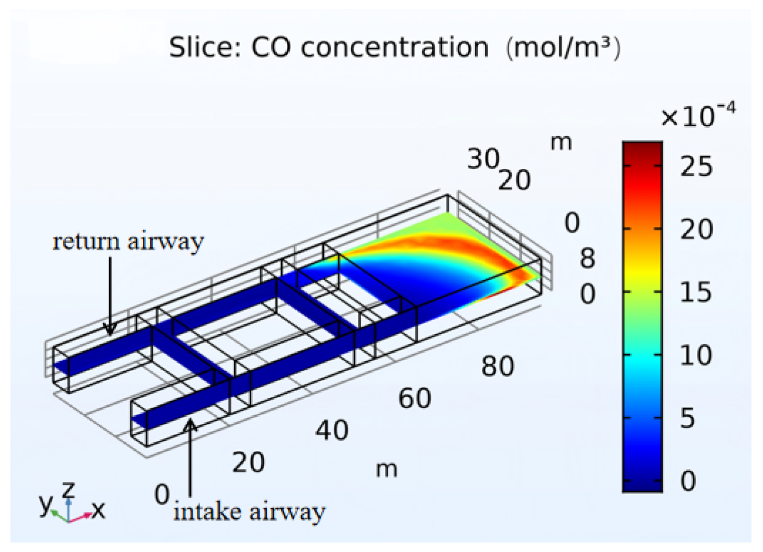
During the cyclic operation period, as shown in Figure 21, the CO concentration in most areas within 30 m of the retention roadway zone ranges between 2.45 and 14.7 ppm, which complies with the regulatory requirements. On the return side, due to the lower pressure compared to the intake side, the pressure difference drives CO from the retention roadway zone into the far corner of the return side, resulting in an excessively high CO concentration there. During the recovery of the inter-section coal pillar, CO concentration monitoring in this area should be strengthened, and personnel should avoid or minimize their stay at this location.
Figure 21.
CO concentration distribution in the roadway during the cyclic operation period.
5. Feasibility Analysis of the Integrated Ventilation Technology of “Excavation–Backfilling–Retention” for Inter-Section Coal Pillar
To systematically evaluate the feasibility of the proposed ventilation technical scheme for the integrated “excavation–backfilling–retention” mining process of the inter-panel coal pillar and gate roads, a comprehensive analysis is conducted from four aspects: the rationality of the ventilation system structure, the validation results of numerical simulation, the engineering adaptability, and the safety assurance capability.
5.1. Analysis of the Structural Rationality of the Ventilation System
The four-stage ventilation system design proposed in this paper (i.e., the bypass roadway excavation period, the excavation period for both gate roads, the excavation period for the inter-section coal pillar, and the cyclic operation period) fully takes into account the dynamic evolution characteristics of the excavation–backfilling–retention method. At each stage, the ventilation mode gradually transitions from forced ventilation by an auxiliary fan to a hybrid ventilation mode dominated by full-pressure ventilation and assisted by an auxiliary fan, thereby avoiding the problems of insufficient airflow or airflow disorder under long-distance, large-section conditions with a single ventilation mode. The rational arrangement of air doors, air bridges, and regulating windows effectively isolates contaminated air from fresh airflow and reduces the risks of airflow short-circuiting and cross-contamination. The overall system structure is clear, the transition is smooth, and the design possesses the fundamental conditions for engineering implementation.
5.2. Internal Consistency Check of the Simulation Results
Three-dimensional steady-state simulations of the four excavation stages were conducted using COMSOL Multiphysics. The results show that during each stage, the roadway temperature is generally controlled to within 20~25.5 °C, which is below the limit of 26 °C specified in the Coal Mine Safety Regulations. In the retention roadway zone, the three zones—namely the heat dissipation zone, the oxidative heating zone, and the self-extinguishing zone—are clearly delineated, with a reasonable temperature gradient and no abnormally high-temperature areas. Except for local areas with insufficient air supply (e.g., 20 m behind the advancing face of the connection roadway, and the corner on the return airway side), the O2 concentration in most areas remains above 20%, meeting the requirements for personnel operation and equipment functioning. In most areas, the CO concentration ranges from 2.45 to 14.7 ppm, which is below the regulatory limit of 24 ppm. Only in local vortex zones or far corners does a transient increase occur (reaching 24–61 ppm), which can be controlled by moving the auxiliary fan forward or adding regulating windows.
The simulation results validate the temperature and gas control capability of the proposed ventilation system under typical working conditions, demonstrating a good safety margin. Although the simulation results have not been directly compared with field measurements, they show good consistency with measured data from mines under similar working conditions [30,31].
5.3. Analysis of Engineering Adaptability
The ventilation system design proposed in this paper fully considers the influence of the “gob-like” structure, formed by the backfill body lagging behind the excavation face, on airflow distribution. By arranging connecting roadways at intervals within the retention roadway zone and adopting a “seal one out of every three” regulator placement pattern, flexible control of the airflow paths is achieved. Meanwhile, the dynamic forward-moving strategy of the auxiliary fan accommodates the variations in ventilation distance caused by the continuous advancement of the excavation face. This system exhibits good adaptability and controllability with respect to fluctuations in geological conditions and changes in excavation rate.
5.4. Assessment of Safety Assurance Capability
From the perspective of disaster prevention and control, the combined air supply of full-pressure ventilation and an auxiliary fan ensures that the area within the retention roadway zone where the oxygen concentration falls below the critical concentration for spontaneous combustion remains controllable and the temperature in the oxidative heating zone does not exceed 25.5 °C, thereby reducing the risk of coal spontaneous combustion. The CO concentration is maintained below the safety limit in the vast majority of areas, and local high-risk areas can be promptly addressed through monitoring and regulatory measures. Except for the farthest corner, the O2 concentration meets the regulatory requirements, indicating that the system has a good oxygen supply assurance capability. Measures such as alternate operation of dual auxiliary fans and optimization of duct joint sealing can enhance the fault tolerance of the ventilation system.
5.5. Scope and Limitations
This paper defines the applicable parameter ranges for the “excavation–backfilling–retention” technology as follows: The coal seam thickness should not be less than 3.0 m. When the thickness falls below this value, the amount of residual coal is small and the spontaneous combustion risk is correspondingly low; although the technology remains feasible, its economic efficiency decreases. For extra-thick coal seams, additional fire prevention and extinguishing measures are required. The technology should be applied in nearly horizontal coal seams; beyond this range, the stability of the backfill body and the air leakage pattern in the goaf become complex, and the technology has not yet been validated. Regarding gas emission conditions, the relative gas emission rate should be lower than 10 m3/t. For high-gas mines, gas extraction measures must be combined. The applicable burial depth ranges from 200 to 600 m; beyond this interval, a dedicated design is necessary. The coal’s spontaneous combustion tendency should be classified as non-prone or moderately prone. For highly prone coal seams, active inerting measures must be adopted. The roof type is required to be moderately stable or above; a soft or broken roof may lead to poor contact of the backfill body with the roof, thereby affecting the isolation effect. When the mining height exceeds 5.0 m, the amount of residual coal increases significantly, and targeted measures such as increasing the compactness of the backfill body, pre-embedding nitrogen injection pipelines, or shortening the service time of the retained roadway should be taken.
Overall, the integrated ventilation system design for the “excavation–backfilling–retention” of the inter-panel coal pillar and gate roads is complete and feasible. The research findings are expected to provide a basis for the implementation of the “excavation–backfilling–retention” integrated technology.
6. Conclusions
(1) Aiming at the integrated “excavation–backfilling–retention” mining process of the inter-section coal pillar and gate roads, a four-stage dynamic ventilation system design is proposed, consisting of the bypass roadway excavation period, the excavation period of both gate roads, the excavation period of the inter-section coal pillar, and the cyclic operation period. This design achieves a smooth transition from forced ventilation by an auxiliary fan to a hybrid ventilation mode dominated by full-pressure ventilation and assisted by an auxiliary fan, effectively addressing key issues such as insufficient air volume, airflow disorder, and high energy consumption during large-section, long-distance excavation.
(2) Using COMSOL numerical simulation software, the temperature, CO concentration, and O2 concentration in the roadways during the four excavation stages were simulated. The simulation results reveal the three-zone distribution pattern of the temperature field in the retention roadway zone and the migration characteristics of O2 and CO gases. The temperature is generally controlled below 26 °C, which complies with the requirements of the Coal Mine Safety Regulations. However, due to the complexity and pioneering nature of this experimental setup, the CFD results of this study should still be regarded as a purely numerical exploration, and their engineering extrapolation and application should be undertaken with caution. In follow-up research, systematic model validation will be carried out after obtaining permission for field measurements.
(3) The integrated ventilation system for the “excavation–backfilling–retention” method adopts a mode combining full-pressure ventilation with local auxiliary fan ventilation, which not only ensures ventilation effectiveness but also reduces ventilation costs. This provides important technical support and safety assurance for green mining and the resource utilization of coal-based solid wastes in China’s coal mines.
Author Contributions
Conceptualization, B.Z.; methodology, B.Z.; software, J.R.; validation, J.R.; resources, S.H.; data curation, J.R.; writing—original draft preparation, J.R.; writing—review and editing, Y.G., W.Y., L.R. and Z.Z. All authors have read and agreed to the published version of the manuscript.
Funding
This research was funded by [Science and Technology Department of Shaanxi Province], grant number [2023-LL-QY-02].
Institutional Review Board Statement
Not applicable.
Informed Consent Statement
Not applicable.
Data Availability Statement
The raw data supporting the conclusions of this article will be made available by the authors on request.
Acknowledgments
During the preparation of this manuscript/study, the authors used COMSOL for the study of gas migration laws and temperature field in roadways. The authors used DeepSeek V4 for language polishing and translation assistance. The authors have reviewed and edited the content as necessary and take full responsibility for the content of the publication.
Conflicts of Interest
Author Liang Ren was employed by the company Shaanxi Yonglong Energy Development and Construction Co., Ltd. Author Zhen Zhang was employed by the company Henan Western Henan Geological Company. The remaining authors declare that the research was conducted in the absence of any commercial or financial relationships that could be construed as a potential conflict of interest.
References
- Wang, S.; Liu, L.; Zhu, M.; Shen, Y.; Shi, Q.; Sun, Q.; Fang, Z.; Ruan, S.; He, W.; Yang, P.; et al. New Approaches to Green and Low-Carbon Development of Coal under the “Dual Carbon” Goals. J. Coal Sci. 2024, 49, 152–171. [Google Scholar] [CrossRef]
- Ge, S.; Liu, S.; Fan, J.; Zhao, Y.; Teng, T. Key Technology System for Modern Low-Carbon Coal-Based Energy Development. J. Coal Sci. 2024, 49, 2949–2972. [Google Scholar]
- Qi, H.; Zhang, N.; Li, J.; Zheng, Z.; Zhu, L.; Guan, Z. Research on the Scientific Mining Model of “Short Charging and Long Mining” in Coal Mines. Coal Sci. Technol. 2019, 47, 1–11. [Google Scholar] [CrossRef]
- Zhang, J.; Ju, F.; Li, M.; Liu, H.; Sun, Z. Exploration of Pathways and Research Perspectives on Green and Low-Carbon Utilization of Coal-Based Solid Wastes. Green Mines 2025, 3, 6–22. [Google Scholar] [CrossRef]
- Zhang, J.; Yao, S.; Qi, Q.; Zhang, W. Review on the Safe, Green, and Efficient Development of Coal Resources in China. Resour. Ind. 2013, 15, 73–78. [Google Scholar]
- Wang, S.; Liu, L.; Zhu, M.; Yu, B.; Zhuang, D.; Qu, H.; He, W.; Shao, C.; Xia, L.; Zhou, J. Integrated scientific issues and technologies for face coal pillar and down-the-tunnel “excavate-fill-retain” process. J. Coal Sci. 2024, 49, 3291–3315. [Google Scholar]
- Deng, J.; Li, B.; Wang, K.; Wang, C. Current Research Status and Prospects of Coal Fire Prevention and Control Technologies in China. Coal Sci. Technol. 2016, 44, 1–7. [Google Scholar]
- Zhang, J.; Zhang, Q. Application of risk accident tree analysis for mine ventilation system safety. Coal Sci. Technol. 2020, 48, 169–173. [Google Scholar]
- Qin, X.; Yun, H.; Shen, B.; Liu, L. Research on ventilation and dust removal technology for long-distance rapid tunneling in single roadways. China Min. 2017, 26, 104–107+113. [Google Scholar]
- Zhao, M.; Qin, X.; Liu, Y.; Shen, B.; Dong, C. Research on the suspension technology of air ducts for long-distance rapid tunneling ventilation systems in single roadways. Coal Sci. Technol. 2015, 43, 82–84. [Google Scholar]
- Guo, Y. Long Pressure Short Drainage Dust Removal by Ventilation Technology in Shendong Mining Area Tunneling Roadway. Saf. Coal Mines 2017, 48. [Google Scholar]
- Chen, Q. Collaborative Research on Hazardous Resource Mining and Goaf Management; Central South University: Changsha, China, 2009. [Google Scholar]
- Zhang, Q.; Wang, Y.; Zhang, J.; Zuo, X.; Yang, J.; Zhang, H.; Ju, F.; Sun, Z.; Wei, L.; Shi, L. Research on Intelligent Solid Filling Mining Method for Coal Mines. J. Coal Sci. 2022, 47, 2546–2556. [Google Scholar]
- Li, B.-R.; Inoue, M.; Shen, S.-B. MineVentilation Network Optimization Based on Airflow Asymptotic Calculation Method. J. Min. Sci. 2018, 54, 99–110. [Google Scholar] [CrossRef] [Scilit]
- Jia, J.; Li, B.; Ke, D.; Wu, Y.; Zhao, D.; Wang, M. Optimization of mine ventilation network feature graph. PLoS ONE 2020, 15, e0242011. [Google Scholar] [CrossRef] [Scilit] [PubMed]
- Liu, X.; Zhang, S. Geological support technology for efficient and rapid tunneling in mudstone roof development areas. Coal Sci. Technol. 2021, 49, 230–234. [Google Scholar]
- Fan, Y.; Mu, X.; Shi, C. Coupling study on gas drainage and spontaneous combustion of floating coal in “U+I” type coal mining face. China Saf. Prod. Sci. Technol. 2017, 13, 96–102. [Google Scholar]
- Zhai, X.; Li, X.; Hou, Q.; Ma, T.; Song, B.; Hao, L. Research and Application of a Graded Early Warning Method for Coal Self-Combustion in Goaf Areas Under Wind-Leakage Conditions. Coal Sci. Technol. 2025, 53, 161–169. [Google Scholar]
- Qin, B.; Ma, D. Research Progress and Challenges in the Prevention and Control of Coal Self-Combustion and Gas Composite Disasters in Mining Caverns. J. Coal Sci. 2025, 50, 392–408. [Google Scholar] [CrossRef]
- Yang, R.; Liu, Y.; Shen, B. Study on the distribution law of airflow field in long-distance large-section tunneling working faces. Coal Sci. Technol. 2015, 43, 64–66. [Google Scholar]
- Zhang, L.; Zha, Z.; Xiao, Z. Research and Application of Intelligent Ventilation Management System for Maping Phosphate Mine. Appl. Sci. 2026, 16, 715. [Google Scholar] [CrossRef] [Scilit]
- Qin, N.; Yu, H.; Wang, P.; Li, X.; Qiao, X.; Cheng, W. Study on multiple influence mechanism of airflow-dust-gas coupling diffusion under large vortex flow echnology. Build. Environ. 2024, 257, 111538. [Google Scholar] [CrossRef] [Scilit]
- Wen, L.; Zhong, D.; Bi, L.; Wang, L.; Liu, Y. Optimization Method of MineVentilation Network Regulation Based on Mixed-Integer Nonlinear Programming. Mathematics 2024, 12, 2632. [Google Scholar] [CrossRef] [Scilit]
- Wang, J.; Cao, A.; Wu, Z.; Lin, L.; Li, Z.; Liu, X.; Li, H.; Long, Y.; Sun, Y. Numerical Stability Analysis of Large Section Tunnels Using the Double-Side Heading Method: ACase Study of Xiamen Haicang Evacuate-Channel. Appl. Sci. 2022, 13, 406. [Google Scholar] [CrossRef] [Scilit]
- Yu, B.-C.; Shao, L.-S. Optimization of the non-stop switchover system control for the main fans used in mining applications. Mech. Ind. 2022, 23, 25. [Google Scholar] [CrossRef] [Scilit]
- Li, H.; Zhang, Q.; Zhang, S. Research on ventilation technology for ultra-long distances in large cross-sections of tunneling faces. Min. Saf. Environ. Prot. 2010, 37, 78–79+86. [Google Scholar]
- Chen, Z.; Jin, B.; Wu, C.; Yang, S. Selection of local ventilation duct diameter. China Saf. Prod. Sci. Technol. 2012, 8, 81–84. [Google Scholar] [CrossRef] [Scilit]
- Yang, J. Research on Ventilation Technology for Ultra-long Distance Tunneling with Extra-large Cross-section in Single Roadways. Coal Sci. Technol. 2017, 45, 65–70. [Google Scholar] [CrossRef]
- Ma, L.; Wei, Z.; Zou, L.; Wei, G.; Liu, X. Experimental Testing and Analysis of CO Gas Sources During Coal Mining. J. China Univ. Min. Technol. 2021, 50, 214–219. [Google Scholar] [CrossRef]
- Wang, X.; Wu, J.; Wu, Y. Analysis of CO Sources and Control Measures for Exceeding Limits at Working Faces in the Shendong Mining Area. Coal Mine Saf. 2013, 44, 132–134. [Google Scholar] [CrossRef]
- Sun, Y.; Wang, S.; Hu, P.; Liang, Y.; Zhang, D. Effect of secondary oxidation of residual coal on the gas concentration field in composite goaf areas. J. Coal Sci. 2023, 48, 139–148. [Google Scholar] [CrossRef]
- Chao, J.; Gu, Q.; Pan, R.; Han, X.; Hu, D.; Liu, W.; Liu, S. Influence of a High-Temperature Environment in Deep Mining on the Characteristics of Coal Spontaneous Combustion. Combust. Sci. Technol. 2022, 196, 589–607. [Google Scholar] [CrossRef] [Scilit]
- Ma, L.; Zou, L.; Ren, L.-F.; Chung, Y.-H.; Zhang, P.-Y.; Shu, C.-M. Prediction indices and limiting parameters of coal spontaneous combustion in the Huainan mining area in China. Fuel 2020, 264, 116883. [Google Scholar] [CrossRef] [Scilit]
- Qi, X.; Li, Q.; Zhang, H.; Xin, H. Thermodynamic characteristics of coal reaction under low oxygen concentration conditions. J. Energy Inst. 2017, 90, 544–555. [Google Scholar] [CrossRef] [Scilit]

Disclaimer/Publisher’s Note: The statements, opinions and data contained in all publications are solely those of the individual author(s) and contributor(s) and not of MDPI and/or the editor(s). MDPI and/or the editor(s) disclaim responsibility for any injury to people or property resulting from any ideas, methods, instructions or products referred to in the content. |
© 2026 by the authors. Licensee MDPI, Basel, Switzerland. This article is an open access article distributed under the terms and conditions of the Creative Commons Attribution (CC BY) license.