


Abstract
Cage-based tilapia farming is highly vulnerable to rapid variations in water-quality parameters, particularly dissolved oxygen (DO) fluctuations, which can cause fish stress, fish mortality, and economic losses. In this study, we developed and field-evaluated an Internet of Things (IoT)- and LoRa-based water-quality-monitoring and aeration-actuation system for open-water tilapia cage farming. The system consists of distributed control nodes, a main node, a cloud database, and a mobile application for real-time monitoring of DO, pH, and water temperature, as well as remote and automatic oxygen-pump actuation. An automatic probe-lifting mechanism is integrated into the control node to reduce probe-submersion duration and mitigate the risk of sensor fouling during field operation. Field validation showed that the node equipped with the probe-lifting mechanism achieved better agreement with the reference instruments than the continuously submerged node, particularly for DO measurement, with RMSE values of 0.186 mg/L and 0.683 mg/L, respectively. A communication-performance evaluation showed 100% packet reception up to 1640 m, whereas packet reception was reduced at the longest tested distance of 2290 m, indicating that the field-deployment range should be interpreted cautiously under the tested LoRa configuration. Detection-latency experiments showed sub-second responsiveness, with average delays of 208.6–289.7 ms for single-hop communication and 438.9–529.4 ms for two-hop communication. Expert evaluation and farmer satisfaction assessment indicated positive perceptions of the system’s usability and practical relevance. However, the study has several limitations, including the short field-validation period, limited sensor replication, and a lack of direct fish production outcome measurements, which should be considered when interpreting the findings. Overall, the proposed system provides a practical platform for water-quality monitoring and aeration actuation in cage-based tilapia farming.
1. Introduction
Nile tilapia is a commercially significant aquaculture species, contributing substantially to income generation and the security of long-term livelihoods in farming communities. The demand for Nile tilapia continues to increase in both domestic and international markets, particularly in the United States and the European Union. However, cage-based Nile tilapia farming in the Sirindhorn Dam area of Ubon Ratchathani Province has recently been hindered by significant challenges, including elevated fish mortality rates. These losses are primarily attributed to deteriorating water quality and abrupt weather fluctuations caused by climate change, leading to rapid reductions in dissolved oxygen levels. Such conditions have resulted in substantial reductions in production yields and farmer incomes [1,2].
Environmental parameters—most notably water temperature and dissolved oxygen concentration—play critical roles in fish growth performance, survival rates, and disease susceptibility [3,4,5]. Effective aquaculture management therefore requires continuous monitoring and timely control of key water-quality indicators. Increasing climate unpredictability and seasonal variability are further exacerbating fluctuations in aquatic environments, underscoring the need for real-time water-quality management systems to minimize fish health risks and economic losses [6].
In response to these challenges, agricultural technologies have rapidly evolved under the smart farming paradigm. IoT-based monitoring systems have been widely adopted to enable real-time monitoring of aquaculture environments, allowing farmers to detect water-quality fluctuations and respond promptly to critical changes [7,8].
Field surveys conducted in the Sirindhorn Dam region have revealed that farmers predominantly rely on supercharger oxygen pumps to increase dissolved oxygen levels in fish cages. However, these systems have several limitations, including high fuel consumption, substantial operational costs, and labor-intensive deployment, particularly in farming areas with widely dispersed cages. The spatial separation of cages also creates significant challenges regarding data communication. These constraints have been addressed by adopting long-range (LoRa) communication technology—a low-power, long-distance wireless communication protocol—as a suitable solution for data transmission in large-scale aquaculture environments [9] with great potential to support sustainable farming practices.
In a previous study, Nawara Chansiri et al. proposed a LoRa-based water-quality-monitoring system for tilapia cage farming in which sensor data were transmitted from distributed monitoring nodes to a central node and subsequently forwarded to a remote server via the internet [10]. However, such systems are subject to critical limitations in practical deployment. In particular, water-quality sensors must remain submerged for prolonged periods, leading to dirt and biofilm accumulation on probe surfaces. This fouling degrades measurement accuracy and significantly shortens sensor lifespan, thereby increasing maintenance costs and reducing system reliability.
The present study is an explicit extension of our work in 2024 [10], in which we presented a LoRa-based prototype for water-quality monitoring in tilapia cage farming. While the 2024 study demonstrated the feasibility of peer-to-peer LoRa communication, remote monitoring, and application-based notification, it did not address several practical issues required for long-term field deployment, including sensor biofouling caused by continuous submersion, automated oxygen-pump control, and end-to-end system responsiveness. Therefore, the current study substantially extends the previous work by introducing an automatic probe-lifting mechanism, integrating oxygen-pump control into the monitoring architecture, and incorporating a more comprehensive field evaluation covering measurement accuracy, communication performance, detection latency, and user satisfaction.
To overcome the previously described challenges, we focused on designing and developing an integrated water-quality-monitoring and control system for Nile tilapia cage farming using IoT and LoRa communication technologies. The proposed system comprises multiple control nodes deployed within fish cages to continuously monitor key water-quality parameters and switch oxygen pumps on/off at distributed locations. These nodes communicate via a peer-to-peer LoRa network, transmitting data to a main gateway node, which aggregates the information and forwards it to a cloud-based server through the internet. Real-time water-quality data and system status are communicated through a smartphone application, enabling farmers to remotely monitor environmental conditions and manually control oxygen pumps as needed.
In addition, the system features an automated alert mechanism that is activated when water-quality parameters exceed predefined thresholds. Automatic oxygen-pump actuation is triggered specifically when dissolved oxygen falls below the critical threshold, because aeration is the direct corrective response to hypoxia. In contrast, abnormal pH or water-temperature conditions generate alerts and management recommendations through the application rather than directly activating the oxygen pump. The oxygen-pump system is powered by solar energy, which is expected to support more sustainable operation and reduce dependence on fuel-based or grid-based energy sources. Importantly, an automatic sensor probe submersion mechanism was introduced into the proposed system. It immerses the sensor only during measurement intervals and retracts it after data acquisition is complete. This approach reduces the duration of probe submersion and was expected to mitigate biofilm formation and sensor drift. In the field evaluation, the lifting-node configuration showed better agreement with reference measurements than the continuously submerged node. However, because the experiment used a limited number of sensor units and was conducted over a relatively short validation period, the improvement is interpreted as an association between intermittent probe immersion and improved measurement agreement rather than definitive proof of long-term biofouling reduction. Collectively, these features make our system well suited to practical deployment in sustainable Nile tilapia cage farming under dynamic environmental conditions.
Despite the growing adoption of Internet of Things (IoT)-based monitoring systems in aquaculture, several important limitations remain insufficiently addressed in the existing literature. Many current systems rely on continuously submerged sensors, which accelerate biofouling and sensor drift, thereby reducing measurement accuracy during long-term deployment. In addition, although LoRa communication has been widely applied in aquaculture-monitoring systems, most studies primarily focus on communication range and signal performance while providing limited analysis of system responsiveness, particularly detection latency under real aquaculture operating conditions. Furthermore, a large proportion of experimental validations have been conducted in laboratory tanks or small pond environments rather than in open-water cage aquaculture systems, where environmental variability and communication constraints are considerably more complex. Consequently, there remains a clear need for an integrated monitoring and control system capable of simultaneously addressing sensor reliability, communication performance, and practical field deployment in cage-based aquaculture environments. Building upon our earlier 2024 monitoring prototype [10], this study makes three main contributions. First, it introduces an automatic probe-lifting mechanism to reduce biofouling and improve long-term sensor reliability. Second, it extends the previous monitoring architecture to an integrated water-quality-monitoring and control system capable of automatic oxygen-pump operation. Third, it encompasses a more comprehensive field validation in open-water tilapia cages, including measurement-accuracy evaluation, communication-performance analysis, detection-latency assessment, and user-satisfaction evaluation.
The structure of this paper is as follows: Section 1 presents the introduction, and Section 2 reviews the related work concerning the application of IoT and LoRa technologies in aquaculture water-quality-monitoring systems. Section 3 details the proposed methodology, while Section 4 discusses the experimental results and analyzes the system’s performance. Finally, Section 5 concludes this study and outlines potential directions for future research.
2. Related Work
The role of Internet of Things (IoT) technologies has been increasingly emphasized in recent advances in smart aquaculture, enabling continuous, real-time monitoring of water quality to mitigate production risks and labor dependency. Early studies consistently reported that dissolved oxygen (DO), pH, and water temperature are the most critical parameters influencing fish growth, survival, and disease susceptibility, particularly under climate-driven environmental variability [1,2,6]. In the same context, IoT-based monitoring systems have been widely adopted to replace manual sampling and narrative observations, which are often incapable of detecting rapid environmental changes in open-water aquaculture environments [7,8].
A substantial body of work has focused on low-power wide-area networks (LPWANs), particularly LoRa and LoRaWAN, to support long-distance data transmission in aquaculture systems. LoRa communication is widely recognized as suitable for large water bodies and rural farming areas because it offers long-range communication with low power consumption and relatively low deployment cost [9]. Building on this communication paradigm, our earlier 2024 work established the feasibility of peer-to-peer LoRa communication for water-quality monitoring in Nile tilapia cage farming [10]. Subsequent studies have further demonstrated LoRa- and LoRaWAN-based architectures for aquaculture monitoring using node-gateway-cloud designs, centralized visualization, and alert functions [11,12,13,14]. Empirical evaluations in these studies generally confirmed reliable communication performance over distances ranging from several hundred meters to multiple kilometers, with acceptable RSSI values, SNRs, and packet delivery rates under real-world or semi-field conditions [11,12,13,14].
Beyond communication reliability, prior research has explored various sensing configurations and system functionalities. Studies have expanded water-quality monitoring beyond DO and pH to include turbidity, salinity, ammonia, total dissolved solids, electrical conductivity, and other parameters, particularly in shrimp farming, biofloc systems, and broader aquaculture environments [15,16,17,18,19]. More advanced systems have incorporated machine learning models to support predictive analytics and decision making in aquaculture management [20]. Other IoT-based fish-farm and tank-scale monitoring studies have emphasized low-cost sensing, calibration, and measurement-accuracy improvement, while also reporting practical issues such as sensor drift and environmental interference [21,22]. Recent biofloc and sustainable aquaculture platforms have integrated real-time monitoring with automatic control mechanisms and broader parameter coverage [23,24], whereas low-cost LoRa-based monitoring designs have provided additional evidence of the feasibility of long-range water-quality observation [25]. A recent systematic review further confirms the rapid growth of IoT-based water-quality monitoring research in aquaculture and highlights the need for more robust field validation and system integration [26].
Despite these advances, several limitations persist in the literature. First, many IoT-based aquaculture systems still rely on continuous sensor submersion, which accelerates biofouling, sensor drift, and probe degradation, particularly for dissolved oxygen and pH sensors. These issues can reduce measurement accuracy and increase maintenance costs during long-term deployment. Although protective casings, calibration models, and robotic maintenance mechanisms have been proposed, such approaches may increase system complexity, cost, or energy consumption, thereby limiting their suitability for small-scale or resource-constrained farms. Second, many existing systems prioritize monitoring and alerting but provide limited empirical evaluation of end-to-end system responsiveness, such as detection latency under real communication conditions, which is critical for timely aeration control in cage-based farming environments. Third, many validations have been conducted in laboratory tanks, aquariums, or pond-scale settings, whereas long-term field evaluations in open-water cage aquaculture remain relatively limited.
Taken together, these findings clearly indicate that studies have confirmed the feasibility and benefits of IoT- and LoRa-enabled water-quality monitoring in aquaculture. However, they also reveal a research gap at the intersection of long-term sensor reliability, field-validated communication performance, and timely automated control in open-water cage-based tilapia farming. In particular, there is a lack of work systematically addressing sensor degradation due to continuous submersion while simultaneously evaluating communication reliability, detection latency, and user acceptance under real farming conditions. Table 1 compares representative studies, summarizing the differences between existing IoT-based aquaculture monitoring systems and the proposed system. The comparison focuses on communication technologies, monitored parameters, automation capability, deployment environments, and reported limitations.
Table 1.
Comparison of existing IoT-based aquaculture-monitoring systems.
As summarized in Table 1, numerous IoT-based monitoring systems have been developed for aquaculture applications. However, most existing systems focus primarily on monitoring functionality and communication range, while several critical issues remain insufficiently addressed. First, many systems rely on continuously submerged sensors, leading to biofouling and sensor drift over time. Second, only a few studies have evaluated system responsiveness, particularly detection latency in real communication networks. Third, many experiments have been conducted in laboratory tanks or pond environments rather than open-water cage aquaculture systems, where environmental variability is more significant. Therefore, this study addresses these limitations by introducing an automatic probe-lifting mechanism, evaluating LoRa communication performance in real cage-farming environments, and analyzing system responsiveness through detection-latency experiments.
Beyond the broader literature, it is important to clarify how the present study relates to our 2024 publication [10] on a LoRa-based water-quality monitoring system for Nile tilapia farming. The earlier work established the feasibility of distributed water-quality monitoring and peer-to-peer data transmission in cage aquaculture. However, it mainly focused on prototype development and overall system feasibility. The present study goes beyond that baseline by transforming the system into an integrated monitoring and control platform, introducing a probe-lifting mechanism to mitigate sensor fouling, and providing more comprehensive experimental validation under real cage-farming conditions. This clarification is important, as it distinguishes the current manuscript as a substantive extension rather than a simple repetition of the earlier study. Table 2 summarizes the main technical and experimental differences between the 2024 prototype and the present study to make the distinction between them more explicit.
Table 2.
Comparison between the 2024 prototype and the present study.
Although previous studies have demonstrated the potential of IoT and LoRa technologies in aquaculture monitoring, several challenges remain unresolved. Many existing systems focus mainly on environmental monitoring without integrating automated control mechanisms for aquaculture management. In addition, little attention has been paid to long-term sensor reliability issues caused by biofouling during continuous water immersion. Furthermore, only a few studies have evaluated system responsiveness, particularly detection latency in multi-hop LoRa communication scenarios. These limitations highlight the need for a more integrated and practical monitoring system capable of addressing sensor durability, communication performance, and real-world deployment in cage-based aquaculture environments.
3. Materials and Methods
The figure below illustrates the architecture we used to develop a water-quality-monitoring and aeration-actuation system for tilapia cage farming using IoT–LoRa.
Figure 1 presents the operational framework of the IoT–LoRa-based water-quality-monitoring and aeration-actuation system for tilapia cage farming. The system consists of distributed control nodes, a main node, a server, and a mobile application. Each control node measures dissolved oxygen (DO), pH, and water temperature and transmits the data to the main node through a peer-to-peer LoRa network. The automatic control logic is parameter-specific. Low-DO conditions directly trigger oxygen-pump actuation, because aeration is an appropriate corrective response to hypoxia. In contrast, abnormal pH or water-temperature conditions trigger warning notifications and management recommendations through the mobile application, because aeration alone cannot directly correct a pH imbalance or an unsuitable temperature. To prevent frequent pump switching near the DO threshold, the control logic incorporates a hysteresis band and a minimum pump-runtime rule. Specifically, the pump is activated when DO falls below the critical threshold and remains active until DO increases above the recovery threshold or until the minimum operating duration has elapsed. This design supports timely aeration while reducing relay wear and unnecessary switching. The main node aggregates data from the control nodes and forwards them to the cloud server for storage, visualization, and user access through the mobile application.
Figure 1.
The system architecture.
3.1. System Circuit Design
This section details the hardware circuit design of the control nodes and the main node implemented in the system. The ESP32 LoRa module (Heltec Automation, Chengdu, China) was selected because it integrates a microcontroller, a LoRa transceiver, and wireless networking capabilities within a single compact platform, enabling low-power operation and long-distance communication suitable for remote aquaculture environments. The DHT22 sensor (Aosong Electronics Co., Ltd., Guangzhou, China) was chosen due to its low cost and acceptable accuracy for monitoring ambient environmental conditions. Dissolved oxygen and pH sensors were selected based on their compatibility with aquaculture water-quality-monitoring standards and ability to interface with RS485 communication. These components provide an optimal balance between measurement reliability, cost efficiency, and deployment feasibility for small-scale aquaculture farms.
Figure 2 is a diagram of the control-node circuit, showing the integration of system components with the ESP32 LoRa microcontroller board (Espressif Systems, Shanghai, China). The system features a DHT22 sensor, which measures ambient air temperature and relative humidity, together with a set of water-quality sensors, including dissolved oxygen (DO), water temperature, and pH sensors. Relay channel 1 controls the power supply to the DO, water temperature, and pH sensors, enabling on-demand operation and improving energy efficiency. These sensors are mechanically integrated with a stepper motor that regulates the vertical movement of the sensor probe assembly. The mechanical structure of the probe-lifting system consists of a stepper motor coupled with a lead screw mechanism that converts rotational motion into controlled vertical movement of the sensor probe assembly. The probe holder is mounted on a sliding guide rail to ensure stable vertical movement and prevent lateral displacement during operation. Two limit switches at the upper and lower boundaries of the motion range define the safe operating positions and prevent mechanical over-travel. The vertical movement distance is approximately 1.3 m, which allows the probe to reach the desired measurement depth of 1.2 m below the surface of the water during each measurement cycle. The stepper motor is controlled through a motor driver module connected to the ESP32 LoRa microcontroller. This module sends step and direction signals to regulate the lifting and lowering speeds of the probe assembly. The control logic for the probe-lifting mechanism is implemented within the Arduino-based firmware running on the ESP32 microcontroller. At the beginning of each measurement cycle, relay channel 1 is activated to power the water-quality sensors. The microcontroller then commands the stepper motor to rotate in the downward direction until the lower limit switch is triggered, indicating that the probe has reached the measurement depth. Sensor measurements are subsequently collected and averaged as described in Section 3.2. After data acquisition is complete, the direction of the motor is reversed so that the probe ascends until the upper limit switch is activated, returning the probe to a dry position above the water surface. This intermittent-immersion approach is intended to reduce the duration of probe submersion and thereby mitigate biofouling risk on the sensor surface. During the field-validation period, this configuration was associated with improved measurement agreement compared with the continuously submerged node.
Figure 2.
The control-node circuit.
The system is powered primarily by solar energy, with photovoltaic panels converting solar radiation into electrical power. The generated energy is stored in a battery, and a solar charge controller regulates the charging process to ensure safe and efficient energy management. This power subsystem supplies energy to the ESP32 LoRa microcontroller during system operation under predefined conditions. Sensor data are transmitted to the main node for processing and forwarded to the server for storage and analysis. In addition, the solar power system features a brushed DC motor that drives an oxygen pump, which is controlled via a second relay. This configuration enables automated aeration support and is expected to improve operational convenience in aquaculture environments. However, direct energy-consumption measurements were not included in the present study.
Figure 3 presents a circuit diagram of the main node, which serves as the central hub that receives and aggregates data from all distributed control nodes. The collected data are transmitted to a central server through a 4G internet network via a Wi-Fi router. A dedicated smartphone application provides real-time visualization of water-quality parameters measured by the control nodes installed in the fish-farming cages, enabling continuous environmental monitoring and informed evaluation of farming conditions. In addition to its data management capacity, the main node is equipped with relay-controlled status indicator lights on the front panel, which provide visual signals indicating system readiness and internet connectivity. The system also enables remote control of oxygenation equipment. Control commands generated via the smartphone application are received by the main node and transmitted to the target control nodes through a peer-to-peer LoRa communication network. These nodes are connected to oxygen pumps, allowing automated and remote activation or deactivation of aeration systems. This communication architecture enhances operational flexibility, reduces the need for manual control of on-site equipment, and supports efficient water-quality management in real-world aquaculture environments.
Figure 3.
The main-node circuit.
3.2. Flowchart of System Design
Programs developed in C for the Arduino platform follow a loop-based execution architecture consisting of two primary functions. The setup() function is executed once upon system startup. It is responsible for initializing system configurations, including communication interfaces, input/output pin modes, and connected hardware peripherals. In contrast, the loop() function is executed repeatedly during runtime and continuously handles data processing, control logic, and system operations for as long as the device remains powered.
Figure 4 illustrates the operational sequence of the control-node devices. The process begins with the setup() phase, during which the system is initialized. This phase includes configuring the ESP32 LoRa microcontroller’s GPIO pins, establishing LoRa network communication, and initializing peripheral components, including the DHT, dissolved oxygen (DO), and pH sensors, and the stepper motor drive system. During the loop() phase, the control node continuously monitors incoming LoRa packets transmitted by neighboring control nodes. Upon receiving a packet, the system verifies the associated node identifier (ID) to determine whether the message is addressed to the current node. If the node ID matches, the system further checks whether the message originated from the main node and identifies the command type for oxygen-pump control. An “ON” command activates relay channel 2 to trigger the oxygen pump, whereas an “OFF” command deactivates the relay to stop pump operation. If the received packet is not intended for the current node, the control node forwards the data to the next neighboring node using a multi-hop communication mechanism, thereby supporting distributed network routing. The control node acquires and processes sensor data at predefined operating intervals of 60 min. The collected measurements are transmitted to neighboring nodes via the LoRa network, enabling efficient data aggregation and reliable forwarding to the main node for centralized monitoring and management.
Figure 4.
Flowchart of the control-node program.
Figure 5 illustrates the system’s operational procedure, executed at predefined intervals of 60 min. At the beginning of each measurement cycle, relay channel 1 is activated to supply power to the sensor probe assembly and associated measurement devices. The system then drives the stepper motor to lower the sensor probe into the water, enabling in situ water-quality measurement. During the measurement phase, the system acquires data on water temperature, dissolved oxygen (DO) levels, and pH, while ambient air temperature and relative humidity are simultaneously recorded using the DHT sensor. Each parameter is sampled 60 times at 1 s intervals. Subsequently, the system processes the collected data by computing the average values for all parameters, thereby mitigating signal noise, reducing measurement interference, and enhancing the accuracy of the water-quality assessment.
Figure 5.
Flowchart of sensor data acquisition and processing.
Figure 6 illustrates the operational workflow of the main node. The process begins with the setup() phase, during which the system is initialized by configuring the GPIO pins of the ESP32 LoRa microcontroller, establishing LoRa network communication, and connecting to a Wi-Fi network to enable internet-based communication with the central server. During the loop() phase, the main node periodically sends data request messages to the server to retrieve the current system control status. If a response is not received, the system waits for 5 s before resending the request. Upon receiving a response, the main node parses the returned JSON data into structured objects corresponding to individual control nodes, including the node identifier (ID) and the on/off status of the associated oxygen pump. These control parameters are stored in the main node’s memory as an array and subsequently transmitted to neighboring nodes via the LoRa network, thereby distributing control commands to the end devices. Concurrently, the main node continuously listens for incoming LoRa packets transmitted by nearby control nodes. When measurement data are received, the main node stores the data locally and forwards them to the server via the internet for centralized storage and real-time visualization within the system. At predefined intervals of one minute, the main node issues an updated data request to the server for the latest control commands for the oxygen pumps. The retrieved information is used to update the internal control state and is redistributed to the control nodes through the LoRa network. This operational cycle enables the system to continuously and efficiently respond to user-initiated control commands issued via the smartphone application or the central management platform.
Figure 6.
Flowchart of the main-node program.
Figure 7 illustrates the workflow of the backend web system, which was developed using PHP to receive data transmitted from field-deployed control devices. Upon reception, the incoming data are processed and stored in a MySQL database (Oracle Corporation, Austin, TX, USA). The workflow begins with verification of data transmission via the HTTP POST method. If no data are detected, the system returns an error response, indicating a communication failure. When valid data are received, the backend system decodes the JSON-formatted payload to extract the relevant parameters, including the node identifier (node ID), dissolved oxygen (DO), pH, water temperature, air temperature, and relative humidity. DO, pH, and water temperature are subsequently evaluated to determine the current water-quality status based on predefined criteria. The system then classifies the water-quality risk status into three alert categories according to the following criteria [3,4,5,27,28]:
Figure 7.
Flowchart of the web backend.
- Critical: DO < 3.5 mg/L, pH < 6.0 or pH > 9.0, or water temperature < 22 °C or >34 °C.
- Surveillance: 3.5 mg/L ≤ DO ≤ 4.9 mg/L, 6 ≤ pH ≤ 6.4 or 8.6 ≤ pH ≤ 9, or 22 °C ≤ water temperature ≤ 24 °C or 31 °C ≤ water temperature ≤ 34 °C.
- Normal: DO ≥ 5 mg/L, 6.5 ≤ pH ≤ 8.5, and 25 °C ≤ water temperature ≤ 30 °C.
When the oxygen pump is configured to operate in automatic mode, the backend system determines pump activation using the dissolved oxygen value specifically, rather than the overall water-quality status alone. If DO falls below the critical threshold of 3.5 mg/L, the system activates the oxygen pump and sends an alert. If DO is within the Surveillance or Normal range, the pump remains off or is deactivated according to the control rule. Abnormal pH or water-temperature values are still classified as Surveillance or Critical for warning purposes; however, they trigger only alerts and management recommendations through the application and do not directly activate the oxygen pump. Finally, all sensor measurements, alert status, and system actions are recorded in the database, and a system log is generated for subsequent review and analysis. Upon successful completion of the processing cycle, the backend system transmits a confirmation message (“Success”) to the control device, thereby concluding the operational sequence for that cycle.
Table 3 summarizes the parameter-specific decision rules used by the backend system to classify water-quality conditions and determine the corresponding system response. The table delineates three operational levels: Critical, Surveillance, and Normal. For dissolved oxygen, the Critical condition is defined as DO < 3.5 mg/L; under this condition, the system activates the oxygen pump and sends an alert, because aeration is the most direct corrective action for low oxygen concentration. When DO is within the Surveillance range of 3.5–4.9 mg/L, the system issues a warning and recommends closer monitoring, whereas DO values of at least 5.0 mg/L are classified as Normal and are recorded without pump actuation.
Table 3.
Parameter-specific alert and actuation logic used in the proposed system.
As indicated in Table 3, abnormal pH and water temperature values are treated primarily as alert and management-recommendation events rather than direct pump-actuation triggers. This distinction is important because aeration can increase dissolved oxygen but cannot directly correct a pH imbalance or an unsuitable water temperature. Therefore, when pH or temperature reaches the Critical range, the system sends an alert and provides a management recommendation through the application, while Surveillance conditions generate warning notifications. This parameter-specific control logic prevents inappropriate use of the oxygen pump, reduces unnecessary energy consumption, and ensures that automatic actuation in the proposed system is specifically associated with low-DO events.
3.3. System Performance Analysis
3.3.1. Expert Performance Evaluation
Five experts with experience in embedded systems, IoT, smart farming, or aquaculture technology evaluated the system’s performance. The questionnaire consisted of 10 items covering four evaluation dimensions: measurement accuracy, communication performance, automated aeration actuation, and practical sustainability. For each item, experts provided integer scores on a 0–100 scale to allow finer discrimination among technical evaluation levels. For reporting consistency with the five-level interpretation used in this study, the raw scores were converted to five-point equivalent scores by dividing each score by 20. The converted scores were then summarized using descriptive statistics, including mean and standard deviation. Because of the small expert sample size, the expert evaluation was interpreted as an expert-opinion assessment rather than as inferential evidence of system effectiveness.
3.3.2. Farmer Satisfaction Evaluation
Farmer satisfaction was evaluated using a pre–post assessment design involving 20 tilapia cage farmers. The questionnaire assessed perceived usability, usefulness, response speed, operational convenience, and overall satisfaction before and after system implementation. Mean, standard deviation, mean difference, 95% confidence interval, degrees of freedom, and p-value were reported. Because Likert-scale data are ordinal, the paired t-test was supplemented with the Wilcoxon signed-rank test to suggest whether the direction of the statistical conclusion was consistent under a non-parametric approach.
3.4. Measurement-Accuracy Evaluation
3.4.1. Experimental Setup
To evaluate the measurement accuracy of the proposed water-quality-monitoring system, a comparative field experiment was conducted using two different control-node configurations: (1) a control node equipped with an automatic probe submersion and probe-lifting mechanism (hereafter referred to as Node-A) and (2) a conventional control node without a probe movement mechanism, in which the probe remained continuously submerged in the water (Node-B). Both control nodes were deployed at the same cage culture site to ensure identical environmental conditions. The probes of both nodes were configured to measure dissolved oxygen (DO), pH, and water temperature at a fixed depth of 1.2 m, which corresponds to the typical operating depth for tilapia cage farming. The distance between the two nodes was kept minimal (within 1 m) to reduce spatial variability while avoiding mutual interference. Reference (ground truth) measurements were obtained by an experienced operator using a standard handheld water-quality measurement instrument, which was treated as the reference device for accuracy evaluation and calibrated according to the manufacturer’s specifications prior to the experiment. Both Node-A and Node-B used the same sensor models, firmware version, sampling interval, communication settings, and data-processing procedure. Before their deployment, the DO, pH, and temperature sensors of both nodes were calibrated following the manufacturers’ instructions and checked against the reference instruments under the same water-sampling conditions. The two nodes were installed within approximately 1 m of each other at the same cage site to minimize spatial variability while avoiding mechanical interference between the probe-lifting system and the continuously submerged probe. However, the nodes did not exchange positions during the experiment; therefore, possible micro-scale location effects and local water movement differences cannot be completely excluded. This limitation is acknowledged in the Discussion Section.
Table 4 summarizes the measurement range, resolution, accuracy or uncertainty, and calibration or verification procedure of the sensors and reference instruments used in the measurement-accuracy evaluation. The same DO, pH, and water-temperature sensor models were used in Node-A and Node-B to minimize hardware-related variation between the probe-lifting and continuously submerged configurations. Before deployment, the control-node sensors were calibrated or verified according to the manufacturers’ recommended procedures and then checked against the handheld reference instruments under the same water-sampling conditions. The AR8406 dissolved oxygen meter (Dongguan Wanchuang Electronic Products Co., Ltd., Dongguan, China) was used as the reference instrument for DO and water temperature, whereas the SmartSensor AS218 (Dongguan Wanchuang Electronic Products Co., Ltd., Dongguan, China) was used as the reference instrument for pH. This specification and calibration information improves reproducibility and clarifies the uncertainty of the reference measurements used for calculating the accuracy metrics.
Table 4.
Sensor and reference-instrument specifications used in the measurement-accuracy evaluation.
3.4.2. Data Collection Protocol
The experiment was conducted continuously for 15 days. Data were collected daily between 06:00 and 18:00, with a sampling interval of 3 h, with measurements taken at 06:00, 09:00, 12:00, 15:00, and 18:00, yielding a total of 75 measurement points per parameter for each node. At each scheduled time, the following procedure was applied:
- Node-A—The probe was automatically lowered into the water, measurements were taken, and the probe was subsequently lifted above the surface of the water.
- Node-B—Sensor readings were recorded at the same depth (1.2 m) without any probe movement.
- The reference instrument was manually submerged by the operator at the same depth and location. To reduce random measurement noise, three consecutive readings were taken, and their average value was used as the reference measurement.
3.4.3. Accuracy Evaluation Metrics
The accuracy of the sensor measurements was evaluated by comparing the readings from each control node with the corresponding reference measurements obtained from the handheld instrument. The primary performance metric used in this study was the root mean square error (RMSE), which quantifies the deviation between sensor readings and reference values. For each water-quality parameter (DO, pH, and temperature), the RMSE was calculated as follows:
where represents the measurement obtained from the control node, denotes the corresponding reference measurement, and n is the total number of measurement samples collected during the experimental period [29]. RMSE values were computed separately for Node-A and Node-B to enable a direct comparison of measurement accuracy between systems with and without the automatic probe movement mechanism.
In addition to the RMSE, the coefficient of determination (R2) was calculated to evaluate the goodness of fit between the sensor measurements obtained from the control nodes and the reference measurements from the handheld instrument. The coefficient of determination represents the proportion of variance in the reference measurements that can be explained by the sensor measurements. An R2 value close to 1 indicates strong agreement between the values measured by the control nodes and the reference instrument, whereas lower values indicate weaker correlation and higher deviation. The R2 value was calculated using the following equation:
where represents the reference measurement obtained from the handheld instrument, represents the corresponding measurement obtained from the control node, denotes the mean value of the reference measurements, and n is the total number of observations [30]. The R2 values were computed separately for Node-A and Node-B to assess the level of agreement between each monitoring node and the reference measurements.
In addition to RMSE and R2, three other indicators were calculated to provide a more complete assessment of sensor performance: mean absolute error (MAE), mean bias error (MBE), and 95% confidence intervals. MAE was used to quantify the average absolute deviation between each node and the reference instrument, whereas MBE was used to identify systematic overestimation or underestimation [29]. The 95% confidence intervals were calculated to describe the uncertainty of the error estimates. Bland–Altman plots were generated for DO, pH, and water temperature to further evaluate agreement between each node and the reference instrument.
where is the measurement obtained from the control node, is the reference measurement, and n is the number of paired observations.
3.5. Remote Communication Performance Analysis
Long-range communication performance was evaluated using two key radio-frequency indicators: the received signal strength indicator (RSSI) and the signal-to-noise ratio (SNR). The RSSI quantifies the power level of a received signal in decibels relative to one milliwatt (dBm), with higher (i.e., less negative) values corresponding to stronger signal reception. RSSI values approaching −30 dBm indicate very strong signals, whereas values near −120 dBm represent weak reception conditions [31]. The signal-to-noise ratio (SNR), expressed in decibels (dB), quantifies the relationship between the power of the received signal and the background noise level. Higher SNR values indicate superior signal quality, as the received signal is more clearly distinguishable from the noise floor [32].
In this study, the RSSI and SNR were obtained directly from the LoRa transceiver output for each received packet and used as empirical indicators of link quality under field-deployment conditions. Because the RSSI and SNR were read directly from the LoRa module rather than calculated from independently measured signal and noise powers, no additional theoretical RSSI or SNR equation was applied in the analysis.
In this experimental setup, five LoRa-enabled nodes were deployed within the Sirindhorn Dam area. One node was designated as the central receiving node (main node), while the remaining four nodes functioned as control nodes. The control nodes were installed at predetermined distances of 438 m, 814 m, 1640 m, and 2290 m from the main node, respectively. All control nodes were mounted on the steel frame structures of tilapia cages at an approximate height of 50 cm above the water surface. During the experimental period, each control node periodically transmitted sensor data packets containing water-quality parameters to the main node at fixed intervals of five minutes. For each node, a total of 20 data packets were sent. This packet number was used to provide indicative field-performance results under the tested deployment conditions rather than a robust statistical characterization of communication reliability.
Communication performance was assessed based on three key metrics: the received signal strength indicator (RSSI), the signal-to-noise ratio (SNR), and packet reception integrity. The RSSI was used to quantify the received signal power at the main node, whereas the SNR was employed to evaluate signal quality relative to the ambient noise level. Packet reception integrity was assessed by analyzing the successful reception of transmitted packets at each distance, serving as an indicator of link reliability and communication robustness.
3.6. Detection-Latency Analysis
Detection latency is a critical performance metric for IoT–LoRa-based water-quality-monitoring and aeration-actuation systems, as it directly reflects a system’s responsiveness to sudden environmental changes, particularly rapid drops in dissolved oxygen levels that may threaten fish survival. In this study, a detection-latency experiment was conducted to quantify the time delay between the occurrence of a trigger event at a control node and the successful reception of the corresponding data packet at the main node. To comprehensively evaluate system responsiveness under different network conditions, two communication configurations were examined: single-hop transmission and two-hop transmission.
The single-hop transmission experiment evaluated the end-to-end latency of direct communication between a control node and the main node without an intermediate relay. In this configuration, the control node transmitted data packets directly to the main node using LoRa communication. The experimental procedure was as follows:
- A control node generated a trigger event, representing a water-quality alert or sensor data transmission.
- Immediately after the event was generated, the control node transmitted a LoRa packet to the main node.
- The transmission timestamp at the control node () and the reception timestamp at the main node () were recorded.
- The detection latency for each transmission was calculated as follows:
The effect of transmission distance was evaluated by conducting experiments at distances of 814 m and 1640 m, with 20 transmission trials performed at each distance. The mean latency and standard deviation were subsequently calculated to characterize the average response time of and variability in single-hop communication.
The two-hop configuration was designed to assess the additional latency introduced by packet forwarding in a multi-hop LoRa network. In this scenario, data packets generated by a control node are relayed through an intermediate node before reaching the main node, reflecting practical deployment conditions in large-scale cage-based aquaculture environments. The steps employed in the experiment were as follows:
- The control node generated a trigger event identical to that used in the single-hop experiment.
- The control node transmitted the packet to an intermediate relay node.
- The relay node recorded the packet reception time (), immediately retransmitted the packet, and logged the retransmission time ().
- The main node recorded the final packet reception time ().
- The total detection latency was calculated as follows:
Two total transmission distances were evaluated: 1640 m and 2290 m. Similarly to the single-hop experiment, each distance configuration was tested 20 times, and the mean latency and standard deviation were computed.
Time synchronization between nodes was maintained using the internal millisecond timer of each ESP32 microcontroller. Prior to the experiment, the system clocks of all nodes were synchronized through a gateway initialization process. Each transmitted packet contained a timestamp field generated by the sending node. The receiving node recorded the arrival timestamp using the same timing reference, enabling accurate calculation of end-to-end transmission latency.
3.7. System Implementation and Field Deployment
Figure 8 illustrates the deployment of a prototype of the proposed water-quality-monitoring and aeration-actuation system, comprising one main node and two distributed control (sensor) nodes. Each control node was powered primarily by a 50 W photovoltaic panel, which simultaneously charged a 12 V, 9 Ah battery to ensure uninterrupted system operation under variable environmental conditions. The system features an ESP32 LoRa SX1262 microcontroller module (Heltec Wireless Stick V3) (Heltec Automation, Chengdu, China), enabling long-range wireless communication within the 863–928 MHz LoRa frequency band for reliable data transmission and reception. In addition, a high-capacity 450 W photovoltaic panel was used to directly supply power to the aeration system. The oxygen pump, driven by a brushed DC motor, was operated through on/off control signals issued by the control node.
Figure 8.
Prototype and electronic circuit connections of the main-node and control-node cabinets.
Figure 9 illustrates the deployment of the proposed water-quality-monitoring system in tilapia cage farms located in Sirindhorn Dam, Ubon Ratchathani Province. The system was installed, tested, and operated under real-world farming conditions to evaluate its practical performance and effectiveness. In this experiment, the control node was mounted on the steel frame of the tilapia cage. Water-quality sensors for measuring water temperature, dissolved oxygen (DO), and pH were submerged to a depth of 1.2 m below the water surface to capture representative environmental conditions within the cage. Additionally, an oxygen pump and a high-capacity 450 W photovoltaic panel were installed on the steel cage to support automated aeration.
Figure 9.
Installing water-quality control-node.
Figure 10 presents the user interface of the OxyLo mobile application, which was developed to support real-time water-quality monitoring and management in cage-based fish-farming systems. The application can be downloaded and installed via the following link: http://www.tlp.ponglert.cs.ubru.ac.th/loadapp.php (accessed on 19 January 2026). The main interface displays a list of all control nodes deployed within the system and provides automatic notifications and audible alerts when water-quality conditions reach the predefined “Surveillance” and “Critical” levels, enabling timely detection of abnormal conditions. Users can select individual control nodes to access detailed, real-time environmental and water-quality information, including air temperature, relative humidity, dissolved oxygen (DO), pH, and water temperature. In addition, the application enables direct remote control of oxygen pumps via a mobile device and supports configurable automatic notification settings, such as alert duration and frequency, as well as condition-based rules for automatic oxygen-pump activation and deactivation. These functionalities enhance the efficiency of water-quality management while reducing the operational and maintenance workload for fish farmers.
Figure 10.
Information and settings from control nodes displayed via the OxyLo application.
Figure 11 shows the web-based platform developed for monitoring and managing water quality in tilapia cage-farming groups. It can be accessed at http://www.tlp.ponglert.cs.ubru.ac.th (accessed on 19 January 2026). The platform visualizes the geographical locations of individual control nodes using map-based markers. By selecting a specific marker, users can view the current water-quality indicators measured at the corresponding location, along with the operational status of the associated sensors. To enhance interpretability, we employed color-coded status indicators: green, yellow, and red represent Normal, Surveillance, and Critical water-quality conditions, respectively. In addition, the platform provides access to historical water-quality data for each control node, enabling temporal analysis and trend monitoring. To ensure data security and integrity, system access is restricted to registered farmers through an authenticated login mechanism.
Figure 11.
The website displays data for each control node on the map as well as historical water-quality information.
4. Results and Discussion
4.1. Results of Measurement-Accuracy Evaluation
This experiment was conducted to evaluate the measurement accuracy of the proposed water-quality-monitoring system, with a particular focus on dissolved oxygen (DO), pH, and water temperature. The collected sensor data were systematically processed and recorded for subsequent accuracy analysis and performance comparison. A total of 75 data collection sessions were conducted over a 15-day field-validation period, from 5 May to 19 May 2025. Measurements were obtained at three-hour intervals between 06:00 and 18:00 at a depth of 1.2 m at tilapia cage-farming sites located in Sirindhorn Dam, Sirindhorn District, Ubon Ratchathani Province. During each data acquisition cycle, measurements from both the automatic probe-lifting node (Node-A) and the non-lifting node (Node-B) were validated against simultaneous in situ measurements obtained using standard reference instruments. The dissolved oxygen level and water temperature were measured using an AR8406 dissolved oxygen meter (Dongguan Wenchang Electronic, Dongguan, China), while pH values were measured using a SmartSensor AS218 pH meter (Dongguan Wenchang Electronic, Dongguan, China). These reference measurements were used to benchmark the control-node outputs and verify the accuracy and reliability of the developed water-quality-monitoring system.
Figure 12, Figure 13 and Figure 14 show clear diurnal variations in dissolved oxygen (DO), pH, and water temperature throughout the monitoring period. Overall, the measurements obtained from Node-A closely followed the reference values, whereas Node-B showed larger deviations, particularly for DO and pH under prolonged submersion conditions.
Figure 12.
Time-series comparison of dissolved oxygen (DO) measurements obtained from the reference instrument, Node-A, and Node-B during the field-validation period.
Figure 13.
Time-series comparison of pH measurements obtained from the reference instrument, Node-A, and Node-B during the field-validation period.
Figure 14.
Time-series comparison of water-temperature measurements obtained from the reference instrument, Node-A, and Node-B during the field-validation period.
Figure 12 compares the dissolved oxygen time series. The reference DO values exhibited a clear daily cycle, with lower values in the early morning, a gradual increase during the day, a peak in the afternoon, and a decline again by 18:00. Node-A closely tracked the reference trend throughout the experiment. In contrast, Node-B increasingly underestimated DO, especially later in the monitoring period, indicating progressive sensor fouling or drift caused by continuous immersion. This pattern is consistent with the substantially higher RMSE and lower R2 observed for Node-B.
Figure 13 presents the pH time series. The pH values remained within a relatively narrow range and followed a consistent daily pattern, increasing from morning to afternoon and then slightly decreasing in the evening. Node-A remained in close agreement with the reference instrument across the monitoring period. By contrast, Node-B showed a gradual negative deviation from the reference values, suggesting mild electrode drift during long-term deployment.
Figure 14 illustrates the water-temperature measurements. All three series showed a similar diurnal pattern, with lower temperatures in the morning, higher values during midday to afternoon, and a decline in the evening. Both monitoring nodes showed closer agreement with the reference instrument for water temperature than for DO and pH. However, Node-A still provided slightly better overall agreement than Node-B, as indicated by the lower RMSE and slightly higher measurement consistency.
Table 5 summarizes the expanded measurement-accuracy analysis calculated from the 75 paired observations in the Supplementary Tables S1–S5. Node-A, which used intermittent probe immersion through the automatic probe-lifting mechanism, showed lower RMSE and MAE values than Node-B for all measured parameters. The largest difference was observed for DO, where Node-A achieved an RMSE of 0.185 mg/L and an MAE of 0.147 mg/L, compared with 0.683 mg/L and 0.563 mg/L for Node-B. The MBE results further indicate that Node-B systematically underestimated DO (MBE = −0.552 mg/L; 95% CI: −0.645 to −0.458 mg/L), whereas the DO bias of Node-A was small and the 95% confidence interval included zero (MBE = −0.021 mg/L; 95% CI: −0.063 to 0.022 mg/L). A similar pattern was observed for pH, where Node-A had lower error (MAE = 0.039) and nearly no systematic bias, while Node-B showed a negative bias (MBE = −0.111). Paired comparisons of absolute errors showed that Node-A performed significantly better than Node-B for DO and pH (p < 0.001), whereas the difference in water-temperature error was not statistically significant (p = 0.506). These results indicate that the probe-lifting configuration was associated with improved agreement with the reference instruments, particularly for DO and pH, under the tested field conditions. Nevertheless, because only one lifting node and one continuously submerged node were compared, these results should be interpreted as evidence of improved measurement agreement rather than definitive proof that biofouling reduction was the sole causal mechanism.
Table 5.
Measurement accuracy and agreement between control-node measurements and reference instrument values (n = 75).
The statistical comparison in Table 5 was performed using paired t-tests on the absolute errors of Node-A and Node-B for each parameter. Although the error analysis strengthens the quantitative validation, the present experiment still had important limitations: only one lifting-node configuration and one continuously submerged-node configuration were tested, nodes did not exchange positions, and visual biofouling inspection was not performed. Future work should include replicated sensors, randomized or exchanged node positions, longer deployment periods, and visual or microscopic inspection of probe fouling to more directly quantify the contribution of intermittent probe immersion to biofouling reduction.
Figure 15, Figure 16 and Figure 17 present the drift-over-time analysis of measurement error for DO, pH, and water temperature, respectively, using paired observations from the 15-day field-validation dataset. As illustrated in Figure 15, Node-A showed no statistically significant DO drift over time, with a slope of 0.00441 mg/L/day (95% CI: −0.00543 to 0.01425; p = 0.375). Its mean DO error changed only slightly from −0.0300 mg/L during days 1–3 to 0.0247 mg/L during days 13–15. By contrast, Node-B exhibited a significant negative DO drift, with a slope of −0.05448 mg/L/day (95% CI: −0.07214 to −0.03682; p < 0.001). The mean DO error for Node-B changed from −0.2527 mg/L during days 1–3 to −0.8727 mg/L during days 13–15, indicating increasing underestimation with prolonged continuous submersion.
Figure 15.
Drift-over-time plot of dissolved oxygen (DO) measurement error between the control-node measurements and the reference instrument.
Figure 16.
Drift-over-time plot of pH measurement error between the control-node measurements and the reference instrument.
Figure 17.
Drift-over-time plot of water-temperature measurement error between the control-node measurements and the reference instrument.
Figure 16 shows a similar pattern for pH. Node-A remained stable throughout the deployment period, with a near-zero drift slope of −0.00027 pH units/day (95% CI: −0.00297 to 0.00244; p = 0.845), and its mean error changed minimally from 0.0080 to 0.0113 pH units between the initial and final three-day periods. In contrast, Node-B showed a significant negative pH drift, with a slope of −0.01316 pH units/day (95% CI: −0.01679 to −0.00953; p < 0.001). Its mean pH error shifted from −0.0233 to −0.1900 pH units, suggesting progressive underestimation during the field deployment.
Figure 17 indicates that water-temperature errors were comparatively stable for both node configurations. Node-A had a drift slope of 0.00807 °C/day (95% CI: −0.00482 to 0.02095; p = 0.216), while Node-B had a slope of −0.00843 °C/day (95% CI: −0.02328 to 0.00642; p = 0.262). Because neither slope was statistically significant, the temperature measurements did not show clear evidence of time-dependent drift during the validation period. Overall, the drift-over-time plots support the interpretation that the probe-lifting configuration was associated with reduced time-dependent measurement drift, particularly for DO and pH. However, because the experiment compared only one lifting node with one continuously submerged node, these results should be interpreted as supportive field evidence rather than definitive causal proof that probe lifting alone eliminated biofouling or sensor drift.
4.2. Testing the System’s Remote Communication Efficiency
Evaluating LoRa communication performance is essential to ensure reliable data transmission in distributed aquaculture-monitoring systems. Because the control nodes are deployed over large areas of water, stable long-range communication is required to guarantee that sensor data can be transmitted to the main node without significant loss or delay. Therefore, this experiment evaluates signal strength (RSSI), signal quality (SNR), and packet delivery performance across multiple transmission distances. This experiment was designed to evaluate the performance of a single-hop long-range wireless communication system. Equipment cabinets were systematically deployed at predetermined distances to ensure controlled and repeatable measurement conditions. The separation distance between the control nodes and the main node was varied across four levels (438, 814, 1640, and 2290 m) at multiple locations within the Sirindhorn Dam area. For each distance, each control node transmitted 20 data packets, as illustrated in Figure 18. The collected transmission data were analyzed to compute the average signal-to-noise ratio (SNR) and the average received signal strength indicator (RSSI). These metrics were used to evaluate signal quality, link reliability, and data transmission integrity as functions of transmission distance.
Figure 18.
The coordinates of the transmitting device, along with the relative distances to the control node.
Table 6 summarizes the LoRa communication configuration used in both the communication-performance and detection-latency experiments. All control nodes and the main node used the same peer-to-peer LoRa settings to ensure that differences in RSSI, SNR, packet reception, and latency were attributable primarily to deployment distance and hop configuration rather than changes in radio parameters. A fixed payload size of 52 bytes was used for each transmission. Acknowledgment and automatic retransmission mechanisms were disabled during the signal-performance tests so that the measured packet reception rate represented direct link performance under the tested field conditions.
Table 6.
LoRa communication configuration used in the field experiment.
The packet reception rate was calculated as the number of successfully received packets divided by the number of transmitted packets at each distance. Because only 20 packets were transmitted per distance, the communication results should be interpreted as indicative field-performance results rather than a definitive maximum-range characterization. The reduced packet reception observed at the longest tested distance indicates that practical communication reliability decreases as distance and field attenuation increase. Table 7 presents the data transmission signal performance of the proposed IoT–LoRa system evaluated under real deployment conditions for cage-based tilapia farming. The results reveal a clear distance-dependent degradation in communication quality, as reflected by the reductions in the RSSI and SNR with increasing transmission range. At 438 m, the system achieved strong link quality, with a high average SNR (9.8 ± 1.2 dB) and RSSI (−78.6 ± 2.4 dBm), ensuring fully reliable packet reception. As the distance increased to 814 m and 1640 m, both indicators declined progressively; however, all transmitted packets were still successfully received, demonstrating robust communication performance under medium-range conditions. At the maximum tested distance of 2290 m, the average SNR dropped slightly below zero (−0.9 ± 1.8 dB), and the RSSI decreased to −109.5 ± 4.6 dBm. Under these near-sensitivity-limit conditions, a small degree of packet loss was observed, with 18 out of 20 packets received. Despite this degradation, the overall reception rate remained high, suggesting the resilience of the LoRa link.
Table 7.
Data transmission signal-performance test results.
At the maximum tested distance of 2290 m, the average SNR dropped slightly below zero (−0.9 ± 1.8 dB), and the RSSI decreased to −109.5 ± 4.6 dBm. Under these near-sensitivity-limit conditions, packet loss was observed, with 18 out of 20 packets received, corresponding to a packet reception rate of 90%. These results suggest that the LoRa link showed promising field performance under the tested conditions, although communication reliability decreased at the longest tested distance. Therefore, the results should be interpreted as indicative field-performance evidence rather than as a definitive maximum-range or reliability characterization.
This communication performance is comparable to that reported for previous LoRa-based monitoring systems. Syed Taha et al. [13] demonstrated that LoRa communication in environmental monitoring applications typically remains stable within distances of 1–2 km depending on antenna gain and environmental conditions. Similarly, Georgantas et al. [25] reported RSSI values ranging from −80 dBm to −110 dBm for LoRa deployments in outdoor monitoring scenarios. The RSSI and SNR values observed in this study fall within similar ranges, suggesting that the proposed communication architecture offers reliable long-range data transmission suitable for cage-based aquaculture environments.
Overall, the results indicate that the selected LoRa transmission parameters provided promising long-range communication performance under the tested open-water cage-farming conditions. However, the packet loss observed at 2290 m suggests that practical deployment over distances exceeding 2 km should consider relay nodes, antenna placement, and site-specific signal conditions.
4.3. Detection-Latency Performance Results
Single-hop transmission experiments were conducted using a control node and the main node deployed within the Sirindhorn Dam area, with separation distances of 814 m and 1640 m, as illustrated in Figure 19. For the two-hop transmission experiments, a three-node topology was implemented, consisting of control node A (source), control node B (relay), and the main node. Two end-to-end transmission distances (1640 m and 2290 m) were evaluated.
Figure 19.
The locations of the transmitting devices used for single-hop detection delay testing.
For the 1640 m configuration, control node 1A was positioned 826 m from control node 1B, while control node 1B was located 814 m away from the main node. For the 2290 m configuration, control node 2A was placed 1170 m away from control node 2B, and control node 2B was positioned 1120 m away from the main node, as shown in Figure 20.
Figure 20.
The coordinate locations of the transmitting devices used in two-hop detection delay testing.
For each experimental configuration, 20 transmission trials were performed. All LoRa modules were configured using the communication parameters specified in Table 6. The collected data were subsequently analyzed to compute the average transmission latency and the corresponding standard deviation.
In addition to the mean and standard deviation, 95% confidence intervals (CIs) of the mean latency were calculated from the 20 transmission trials conducted for each communication configuration. Table 8 reports the detection-latency performance of the proposed IoT–LoRa system under single- and two-hop communication configurations deployed in a real cage-based tilapia-farming environment. For single-hop communication, the mean latency was 208.6 ms at 814 m (SD = 33.4 ms; 95% CI: 193.0–224.2 ms) and increased to 289.7 ms at 1640 m (SD = 41.8 ms; 95% CI: 270.1–309.3 ms). For the two-hop configuration, the mean latency was 438.9 ms at 1640 m (SD = 52.6 ms; 95% CI: 414.3–463.5 ms) and 529.4 ms at 2290 m (SD = 66.9 ms; 95% CI: 498.1–560.7 ms). These results indicate that latency increased with both transmission distance and hop count, as expected, given that the two-hop topology introduced packet forwarding at the intermediate node. Nevertheless, all mean latencies remained below one second under the tested field conditions.
Table 8.
Detection-latency performance results.
The confidence intervals provide a clearer estimate of uncertainty than the mean and standard deviation alone. However, because each configuration was evaluated using 20 trials under a fixed set of LoRa parameters and field conditions, the reported latency values should be interpreted as representative field-performance results rather than universal latency limits for all LoRa deployments. Although the observed range of approximately 208.6–529.4 ms is consistent with reported LoRa monitoring delays in the literature, a direct comparison among studies should be made cautiously because latency depends on spreading factor, bandwidth, coding rate, payload size, acknowledgment settings, retransmission policy, distance, and environmental obstruction.
Overall, the results indicate that the proposed LoRa architecture provided sub-second responsiveness in the tested single- and two-hop configurations. This level of responsiveness is suitable for timely water-quality alert transmission and aeration-actuation commands in cage-based aquaculture monitoring. At the same time, longer-distance and multi-hop deployments should be evaluated with additional trials and under different environmental conditions before generalizing the latency performance to all field scenarios.
Although the detection-latency results indicate that the proposed system can transmit data and deliver pump-actuation commands with a sub-second response time, the water-quality recovery effect after oxygen-pump activation was not directly quantified. Specifically, DO recovery curves after pump operation, comparisons of DO stability with and without automatic aeration, pump response under naturally occurring low-DO events, energy savings during automatic operation, and fish survival or production outcomes were not evaluated in this field trial. Therefore, the term “control” in this study should be interpreted specifically as aeration actuation in response to low-DO conditions rather than complete regulation of all water-quality parameters. Abnormal pH and water-temperature conditions were treated as alert and management-recommendation events because aeration does not directly correct pH imbalance or unsuitable temperature. Future work should include controlled field experiments comparing manual and automatic aeration strategies, DO recovery rates, pump operating durations, energy consumption, and fish production outcomes.
4.4. Efficiency of the IoT–LoRa-Based Water-Quality-Monitoring and Aeration-Actuation System
The system’s performance was evaluated by five experts with professional experience in software development; the results are shown in Table 9. A structured questionnaire based on a five-point Likert scale was employed to assess the system’s suitability, efficiency, and operational availability under real-world deployment conditions in a cage aquaculture tilapia farm. The evaluation criteria encompassed measurement accuracy, communication performance, automated control functionality, and overall system sustainability.
Table 9.
Results of expert performance evaluation.
The assessment presented in Table 10 involved 20 tilapia cage farmers and compared satisfaction levels before and after the proposed system was implemented. Descriptive statistics, including the mean and standard deviation, were used to summarize user responses, while a paired t-test was applied to determine the statistical significance of changes observed following system deployment, thereby allowing evaluation of the system’s impact on farm operations.
Table 10.
Farmer satisfaction before and after system implementation.
The performance evaluation results summarized in Table 9 demonstrate that the proposed IoT–LoRa-based water-quality-monitoring and aeration-actuation system exhibits a high level of technical readiness and operational suitability for real-world deployment in cage-based tilapia farming. Overall, the system achieved a high mean score of 4.11 (S.D. = 0.57), indicating strong expert agreement regarding its effectiveness across multiple performance dimensions. The experts rated the automatic probe-lifting and -lowering mechanism most favorably, giving it a very high score (4.50 ± 0.50). This result indicates that the experts perceived the probe-lifting mechanism as a practically useful design for reducing probe-submersion duration and mitigating biofouling risk. This perception is consistent with the measurement-accuracy results, in which the probe-lifting node showed better agreement with the reference instruments during the field-validation period. Similarly, the high ratings for measurement accuracy (4.30 ± 0.55) suggest that the system can reliably monitor dissolved oxygen, pH, and water temperature under dynamic field conditions.
The IoT–LoRa architecture and communication performance also received consistently favorable evaluations (with means between 3.95 and 4.10), reflecting the adequacy of the RSSI, SNR, and packet delivery reliability for long-distance operation in open-water environments. Importantly, the system’s detection latency (4.00 ± 0.57) was considered appropriate for timely oxygen-pump control, indicating that sub-second response times are sufficient to support proactive mitigation of hypoxic events. Furthermore, the experts acknowledged the benefits of automated oxygen-pump control (4.20 ± 0.54) and solar energy integration (4.35 ± 0.52), highlighting reduced operational risk, improved sustainability, and lower energy costs. Although slightly lower scores were observed for scalability (3.80 ± 0.66) and long-term stability (3.90 ± 0.63), these ratings still fall within the high-performance category, suggesting that the system is robust while leaving scope for future expansion and optimization.
Table 10 shows that farmer satisfaction increased consistently across all 12 assessment items after implementation of the IoT–LoRa-based water-quality-monitoring and aeration-actuation system. Paired t-tests indicated statistically significant improvements for every item (all p < 0.001), and the Wilcoxon signed-rank tests produced the same conclusion (all p < 0.001), supporting the robustness of the pre–post comparison. The overall participant-level satisfaction score increased from 2.23 (SD = 0.16) before implementation to 4.48 (SD = 0.17) after implementation, with a mean difference of 2.25 points (95% CI: 2.14–2.36; t(19) = 43.86; p < 0.001).
The largest item-level improvements were observed for the water-quality alert function and the intention to recommend the system to other farmers, both with mean differences of 2.40 points. Items related to real-time monitoring, remote oxygen-pump control, emergency response, perceived reduction in fish losses, and overall satisfaction also showed substantial gains, with post-implementation mean scores ranging from 4.30 to 4.60. These findings indicate high perceived usefulness and acceptance among farmers. Nevertheless, the results represent user perceptions from a sample of 20 farmers and should be interpreted as satisfaction and acceptance evidence rather than direct proof of long-term economic savings, fish-survival improvement, or production gains.
5. Conclusions
In this study, we developed and field-evaluated an IoT–LoRa-based water-quality-monitoring and aeration-actuation system for tilapia cage farming. The system integrates distributed sensing nodes, peer-to-peer LoRa communication, a main node, a cloud database, a mobile application, oxygen-pump actuation, and an automatic probe-lifting mechanism. The field results showed that measurements obtained in the lifting-node configuration were closer to reference measurements than those obtained in the continuously submerged configuration, particularly for DO. LoRa testing demonstrated reliable packet reception up to 1640 m under the tested field conditions, although reduced packet reception at 2290 m indicates that the communication range should be interpreted cautiously. Detection-latency results showed sub-second responsiveness for both single- and two-hop communication. Expert and farmer evaluations further indicated positive perceptions of usability and practical relevance. Nevertheless, this study has several limitations: the field-validation period was relatively short, only a limited number of sensor nodes were compared, node positions were not randomized or exchanged, communication testing used a small number of packets per distance, long-term energy performance was not measured, and direct fish production outcomes were not evaluated. Future research should include longer deployments, replicated sensors, probe-fouling image analysis, DO recovery experiments after pump activation, detailed solar energy performance evaluation, and assessment of fish growth, survival, and production outcomes.
Supplementary Materials
The following supporting information can be downloaded at: https://www.mdpi.com/article/10.3390/app16115308/s1, Table S1: Raw data: Time-series measurements used for RMSE accuracy, Table S2: Raw data: LoRa signal performance, Table S3: Raw data: Detection latency, Table S4: Raw data: Experts performance of IoT-LoRa, Table S5: Raw data: Farmer Satisfaction before and after IoT-LoRa Implementation.
Author Contributions
Conceptualization, P.S. and S.M.; methodology, P.S. and S.M.; software, P.S., C.K., N.C., B.C., P.W. and P.C.; validation, P.S., S.M. and C.K.; formal analysis, P.S. and S.M.; investigation, P.S., N.C., B.C., P.W. and P.C.; resources, P.S. and S.M.; data curation, P.S., N.C. and B.C.; writing—original draft, P.S.; writing—review and editing, S.M. and P.S.; visualization, P.S.; supervision, S.M.; project administration, S.M.; funding acquisition, S.M. All authors have read and agreed to the published version of the manuscript.
Funding
This research received no external funding.
Institutional Review Board Statement
The study was conducted in accordance with the Declaration of Helsinki and was approved by the Institutional Review Board, Association of Legal & Political Studies (ALPS-IRB), Thailand (protocol code ALPS-IRB No. 2026/03/B02; Certificate of Approval No. ALPS-IRB-2026-3-0002; date of approval: 1 April 2026).
Informed Consent Statement
Informed consent was obtained from all subjects involved in the study. Participant information sheets and informed consent forms approved by ALPS-IRB were used for all participants. No individually identifiable participant information is reported in this article.
Data Availability Statement
The datasets generated during the current study are available in the Supplementary Materials.
Acknowledgments
The authors gratefully acknowledge the tilapia farmers at Sirindhorn Dam, Sirindhorn District, Ubon Ratchathani Province, Thailand, for allowing the research team to conduct field experiments in their aquaculture areas and for their valuable cooperation and support throughout the study.
Conflicts of Interest
The authors declare no conflicts of interest.
References
- Salikara, P.; Bejranonda, S. Commercial investment of Nile tilapia (Oreochromis niloticus Linn.) culture in Nakhon Pathom Province. J. Econ. Manag. Strategy 2016, 3, 40–54. [Google Scholar]
- Truong, T.M.; Phan, C.H.; Tran, H.V.; Duong, L.N.; Nguyen, L.V.; Ha, T.T. To develop a water quality monitoring system for aquaculture areas based on agent model. In Proceedings of the Fourth International Congress on Information and Communication Technology (ICICT 2019); Springer: London, UK, 2019; Volume 2, pp. 47–58. [Google Scholar]
- Food and Agriculture Organization of the United Nations. Oreochromis niloticus (Nile Tilapia): Cultured Aquatic Species Information Programme; FAO Fisheries & Aquaculture Division: Rome, Italy, 2023; Available online: https://www.fao.org/fishery/culturedspecies/oreochromis_niloticus (accessed on 20 January 2026).
- Abdel-Tawwab, M.; Hagras, A.E.; Elbaghdady, H.A.M.; Monier, M.N. Dissolved Oxygen Level and Stocking Density Effects on Growth, Feed Utilization, Physiology, and Innate Immunity of Nile Tilapia, Oreochromis niloticus. J. Appl. Aquac. 2014, 26, 340–355. [Google Scholar] [CrossRef] [Scilit]
- El-Sayed, A.-F.M. Tilapia Culture; Academic Press: London, UK, 2019. [Google Scholar]
- Sriyasak, P.; Whangchai, N.; Chitmanat, C.; Promya, J.; Lebel, L. Impacts of climate and season on water quality in aquaculture ponds. Asia-Pac. J. Sci. Technol. 2017, 19, 743–751. [Google Scholar]
- Duang-Ek-Anong, S.; Pibulcharoensit, S.; Phongsatha, T. Technology readiness for Internet of Things (IoT) adoption in smart farming in Thailand. Int. J. Simul. Syst. Sci. Technol. 2019, 20, 1–6. [Google Scholar] [CrossRef] [Scilit]
- Tawfeeq, A.; Al Wahaibi, H.A.S.; Vijayalakshmi, K. IoT based aquaculture system with cloud analytics. Int. J. Appl. Eng. Res. 2019, 14, 4136–4142. [Google Scholar]
- Charan, K.; Mingkwan, S.; Pairoj, D.; Athikom, S.; Kamon, B. LoRa-based mesh network for transmitting status data from forest fire heat detection sensors. J. Ind. Technol. Thepsatri Rajabhat Univ. 2023, 18, 29–39. (In Thai) [Google Scholar]
- Chansiri, N.; Sangkaphet, P.; Chaleamwong, B.; Kaewklom, C.; Makdee, S. Water quality monitoring system for Nile tilapia farming using LoRa technology. In Proceedings of the 8th International Conference on Information Technology (InCIT 2024); IEEE: Piscataway, NJ, USA, 2024; pp. 578–583. [Google Scholar]
- Li, M.; Lin, C.; Ren, J.; Jiang, F. A wireless ecological aquaculture water quality monitoring system based on LoRa technology. In Proceedings of the International Conference on Wireless Communication, Network and Multimedia Engineering (WCNME 2019); Atalantis Press: Dordrecht, The Netherlands, 2019; pp. 5–7. [Google Scholar]
- Boppana, L.; Madhu, K.; Vaibhav, C.P.R. Aquaculture water monitoring system using LoRaWAN. In Proceedings of the IEEE 11th Region 10 Humanitarian Technology Conference (R10-HTC 2023); IEEE: Piscataway, NJ, USA, 2023; pp. 1095–1099. [Google Scholar]
- Reduan, A.; Sani, M.M.; Kutty, S.B.; Isa, N.M.; Yusof, Y. Design of an IoT water quality monitoring system for tropical fish aquaculture. Int. J. Acad. Res. Bus. Soc. Sci. 2021, 11, 173–183. [Google Scholar] [CrossRef] [Scilit]
- Syed Taha, S.N.; Abu Talip, M.S.; Mohamad, M.; Azizul Hasan, Z.H.; Tengku Mohmed Noor Izam, T.F. Evaluation of LoRa network performance for water quality monitoring systems. Appl. Sci. 2024, 14, 7136. [Google Scholar] [CrossRef] [Scilit]
- Fitriansyah, A.; Nugroho, R.A.; Meitarice, S. Water quality monitoring and control system for fish farmers based on Internet of Things. Ing. Syst. Inf. 2024, 29, 1107–1113. [Google Scholar] [CrossRef] [Scilit]
- Nagothu, S.K.; Bindu Sri, P.; Anitha, G.; Vincent, S.; Kumar, O.P. Advancing aquaculture: Fuzzy logic-based water quality monitoring and maintenance system for precision aquaculture. Aquac. Int. 2025, 33, 32. [Google Scholar] [CrossRef] [Scilit]
- Adi, D.P.; Yassir, M.; Purnama, I.; Ardi, I.; Wahyu, Y.; Mariana, L.; Novita, H.; Mahabror, D.; Zulkarnain, R.; Wirawan, A.; et al. Innovative monitoring of water environment in vaname shrimp farming based on LoRaWAN. J. Southwest Jiaotong Univ. 2024, 59, 18. [Google Scholar] [CrossRef] [Scilit]
- Espeña, G.D.; Libao, F.J.D.; Von Jansen, G.; De Luna, N.A.P.U.; Mojica, A.J.N.; Rivera, M.D. Enhancing water quality control and monitoring in shrimp farms with LoRaWAN technology. In Proceedings of the IEEE 15th International Conference on Humanoid, Nanotechnology, Information Technology, Communication and Control, Environment, and Management (HNICEM 2023); IEEE: Piscataway, NJ, USA, 2023; pp. 1–6. [Google Scholar]
- Adi, P.D.P.; Ardi, I.; Plamonia, N.; Wahyu, Y.; Novita, H.; Mahabror, D.; Zulkarnain, R.; Wirawan, A.; Prastiyono, Y.; Waryanto, W.; et al. Analysis of IoT-LoRa to improve LoRa performance for vaname shrimp farming monitoring system. J. Ilm. Tek. Elektro Komput. Dan Inform. 2024, 10, 99–122. [Google Scholar] [CrossRef] [Scilit]
- Ahmed, F.; Bijoy, M.H.I.; Hemal, H.R.; Noori, S.R.H. Smart aquaculture analytics: Enhancing shrimp farming in Bangladesh through real-time IoT monitoring and predictive machine learning analysis. Heliyon 2024, 10, e37330. [Google Scholar] [CrossRef] [Scilit]
- Chen, C.-H.; Wu, Y.-C.; Zhang, J.-X.; Chen, Y.-H. IoT-Based Fish Farm Water Quality Monitoring System. Sensors 2022, 22, 6700. [Google Scholar] [CrossRef] [Scilit]
- Jais, N.A.M.; Abdullah, A.F.; Kassim, M.S.M.; Abd Karim, M.M.; M, A.; Muhadi, N.-A. Improved Accuracy in IoT-Based Water Quality Monitoring for Aquaculture Tanks Using Low-Cost Sensors: Asian Seabass Fish Farming. Heliyon 2024, 10, e29022. [Google Scholar] [CrossRef] [Scilit] [PubMed]
- Al Mamun, M.R.; Ashik-E-Rabbani, M.; Haque, M.M.; Upoma, S.M. IoT-Based Real-Time Biofloc Monitoring and Controlling System. Smart Agric. Technol. 2024, 9, 100598. [Google Scholar] [CrossRef] [Scilit]
- Zuhaer, A.; Khandoker, A.; Enayet, N.; Partha, P.K.P.; Awal, M.A. Sustainable Aquaculture: An IoT-Integrated System for Real-Time Water Quality Monitoring Featuring Advanced DO and Ammonia Sensors. Aquac. Eng. 2025, 112, 102620. [Google Scholar] [CrossRef] [Scilit]
- Georgantas, I.; Mitropoulos, S.; Katsoulis, S.; Chronis, I.; Christakis, I. Integrated Low-Cost Water Quality Monitoring System Based on LoRa Network. Electronics 2025, 14, 857. [Google Scholar] [CrossRef] [Scilit]
- Flores-Iwasaki, M.; Guadalupe, G.A.; Pachas-Caycho, M.; Chapa-Gonza, S.; Mori-Zabarburú, R.C.; Guerrero-Abad, J.C. Internet of Things (IoT) Sensors for Water Quality Monitoring in Aquaculture Systems: A Systematic Review and Bibliometric Analysis. AgriEngineering 2025, 7, 78. [Google Scholar] [CrossRef] [Scilit]
- Boyd, C.E. Water Quality: An Introduction; Springer Science & Business Media: New York, NY, USA, 2000. [Google Scholar]
- Azaza, M.S.; Dhraïef, M.N.; Kraïem, M.M. Effects of Water Temperature on Growth and Sex Ratio of Juvenile Nile Tilapia, Oreochromis niloticus (Linnaeus), Reared in Geothermal Waters in Southern Tunisia. J. Therm. Biol. 2008, 33, 98–105. [Google Scholar] [CrossRef] [Scilit]
- Chai, T.; Draxler, R.R. Root mean square error (RMSE) or mean absolute error (MAE)?—Arguments against avoiding RMSE in the literature. Geosci. Model Dev. 2014, 7, 1247–1250. [Google Scholar] [CrossRef] [Scilit]
- Nagelkerke, N.J.D. A note on a general definition of the coefficient of determination. Biometrika 1991, 78, 691–692. [Google Scholar] [CrossRef]
- Azhar Muzafar, M.I.Z.; Mohd Ali, A.; Zulkifli, S. A Study on LoRa SX1276 Performance in IoT Health Monitoring. Wirel. Commun. Mob. Comput. 2022, 2022, 6066354. [Google Scholar] [CrossRef] [Scilit]
- The Things Network. RSSI and SNR. The Things Network Documentation. 2023. Available online: https://www.thethingsnetwork.org/docs/lorawan/rssi-and-snr/ (accessed on 23 January 2026).
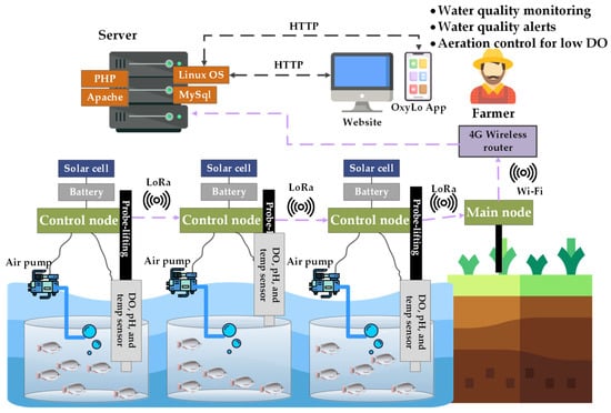
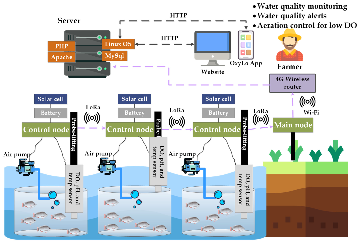
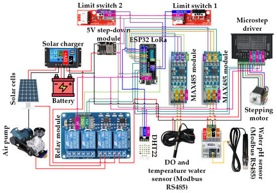
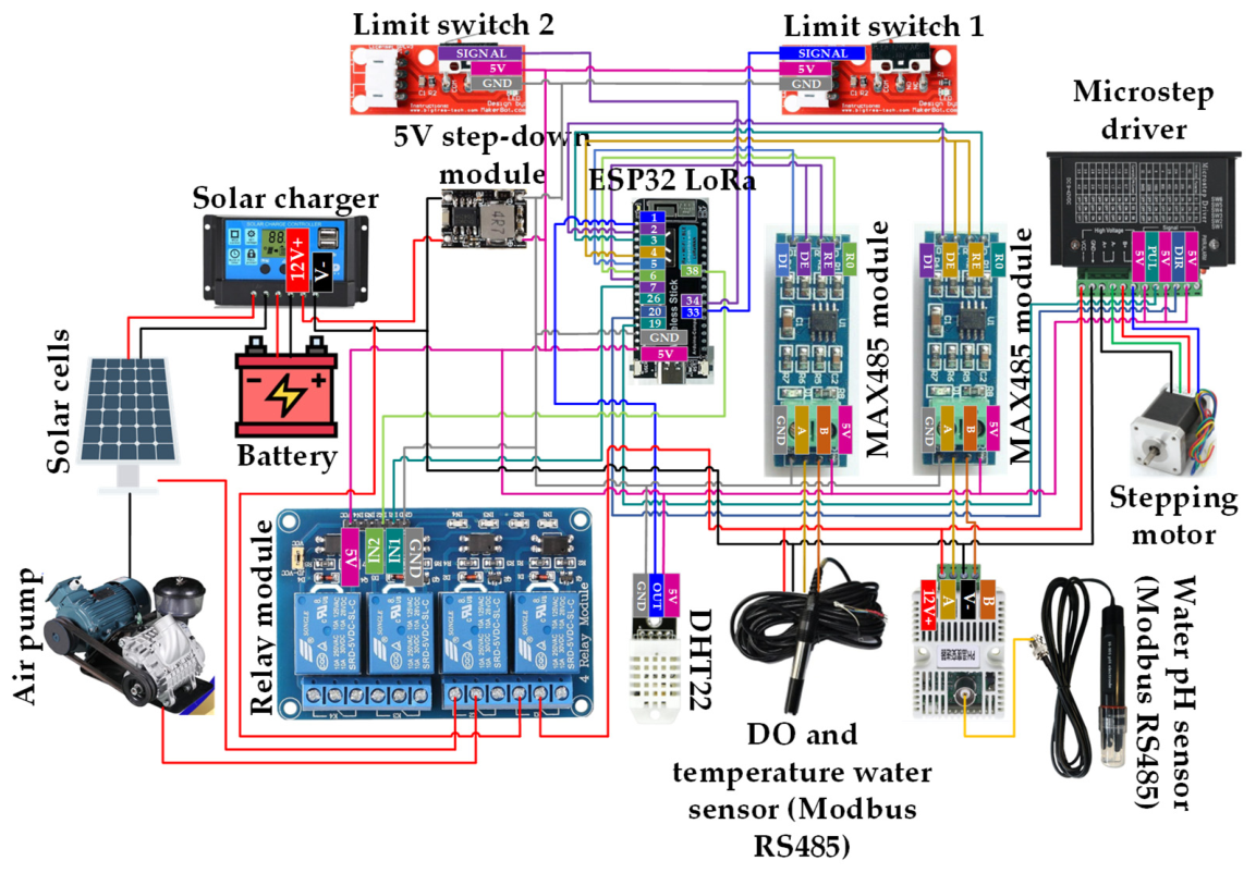
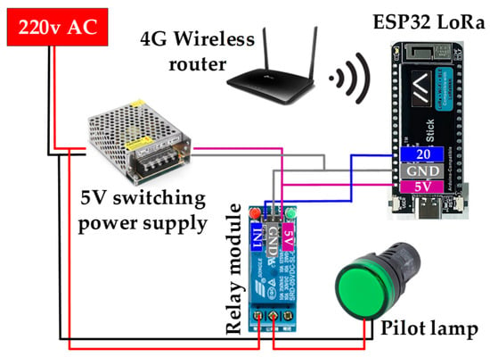
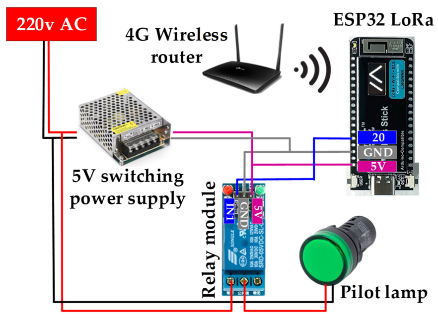
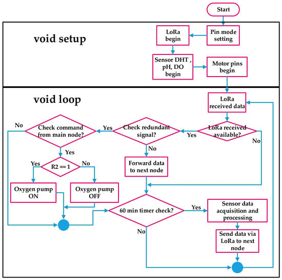
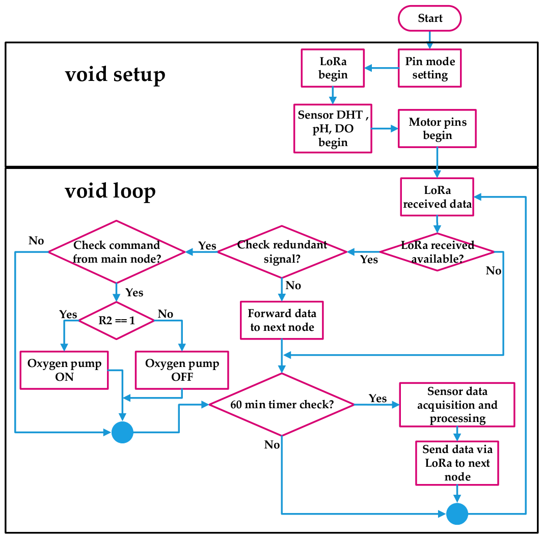
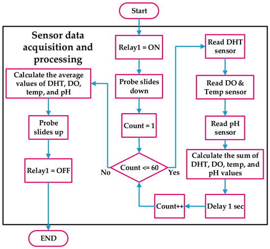
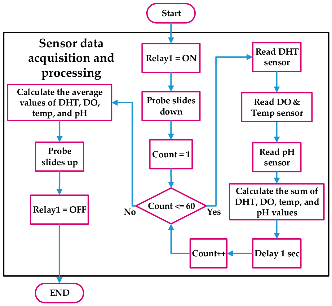
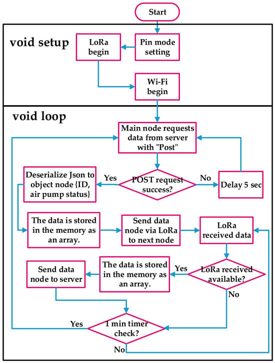
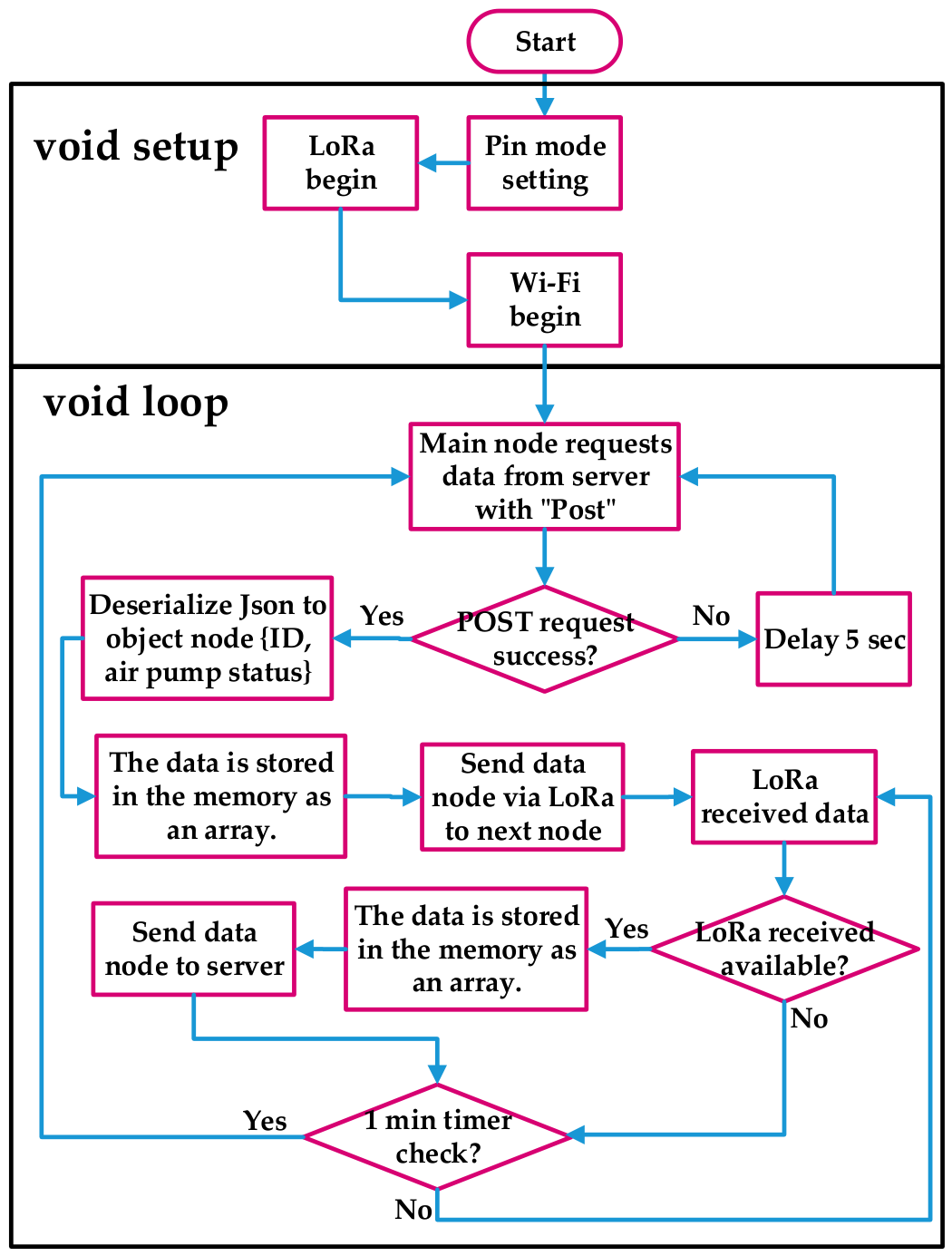
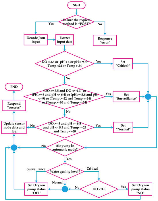
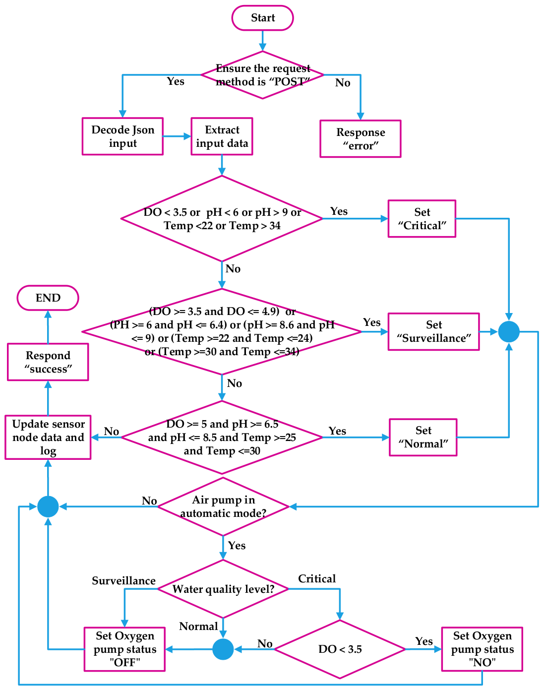
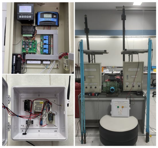
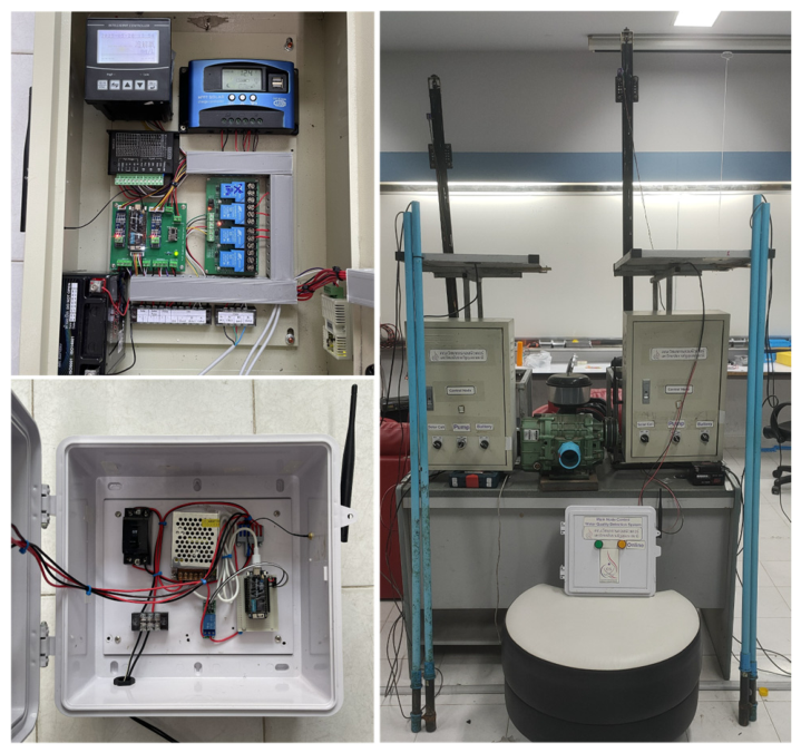
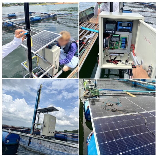
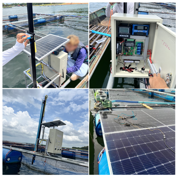
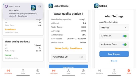
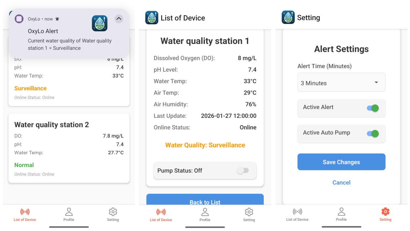
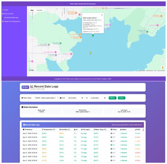
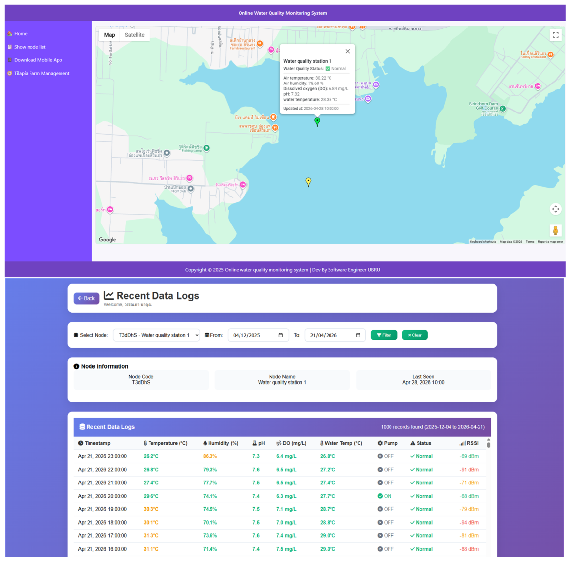
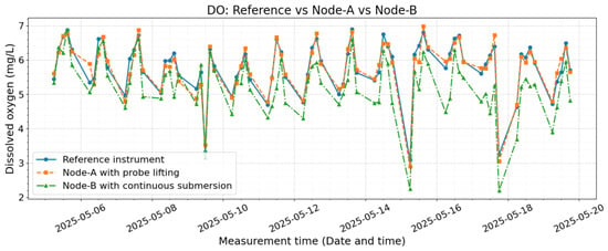
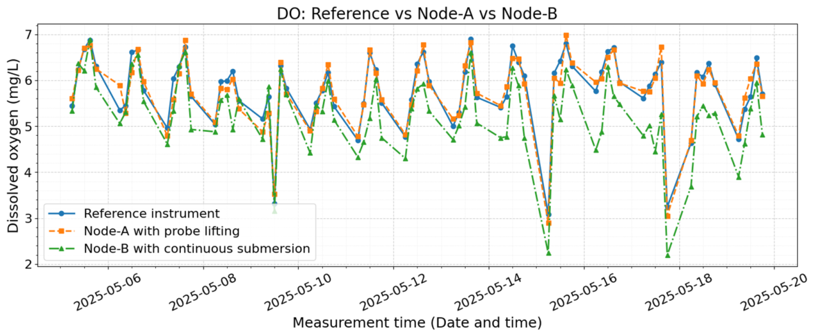
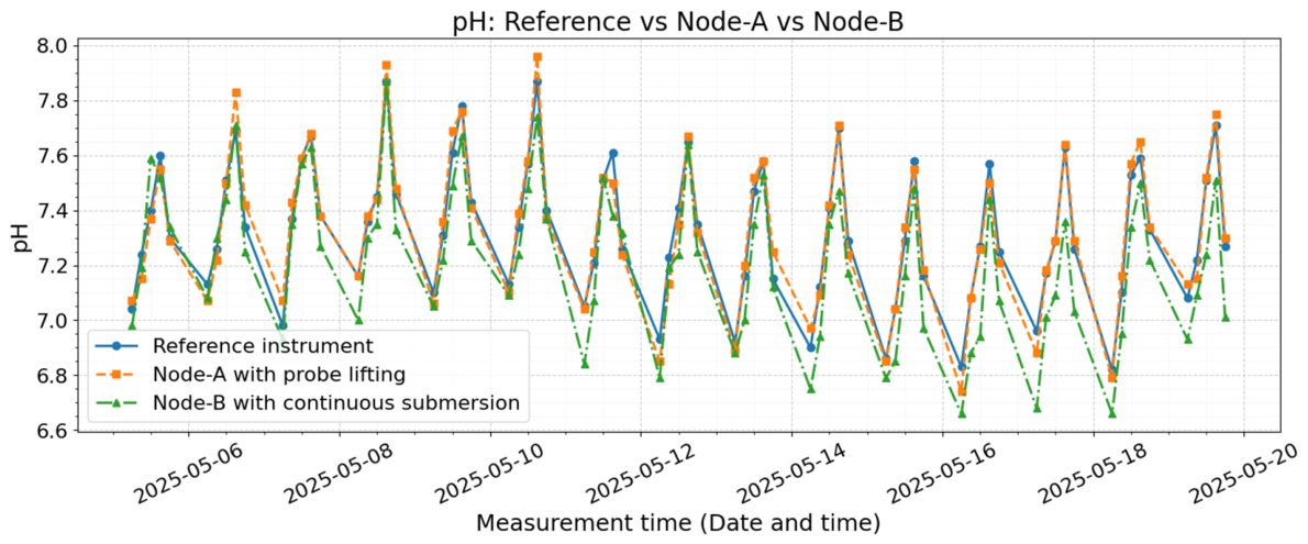
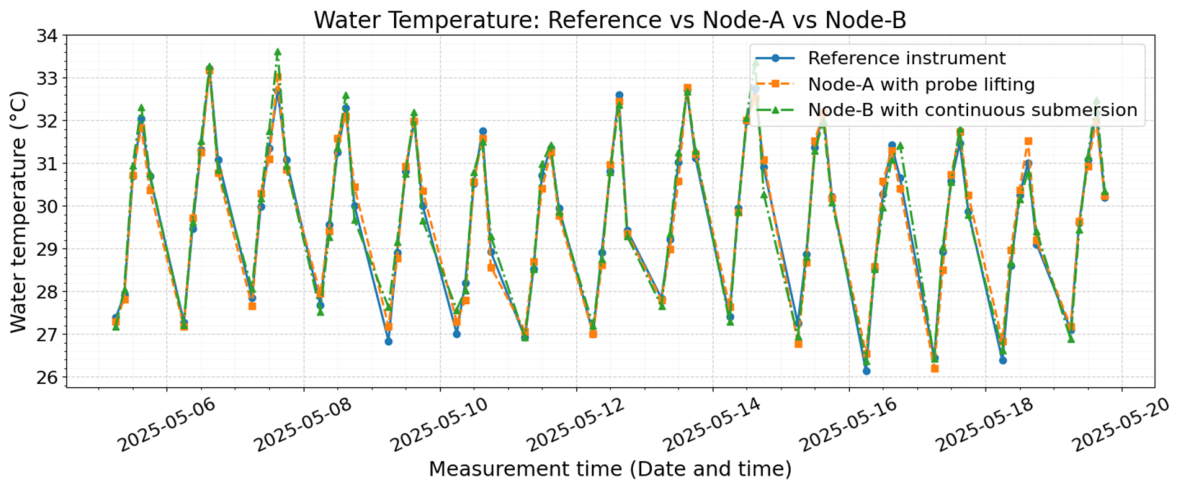
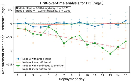
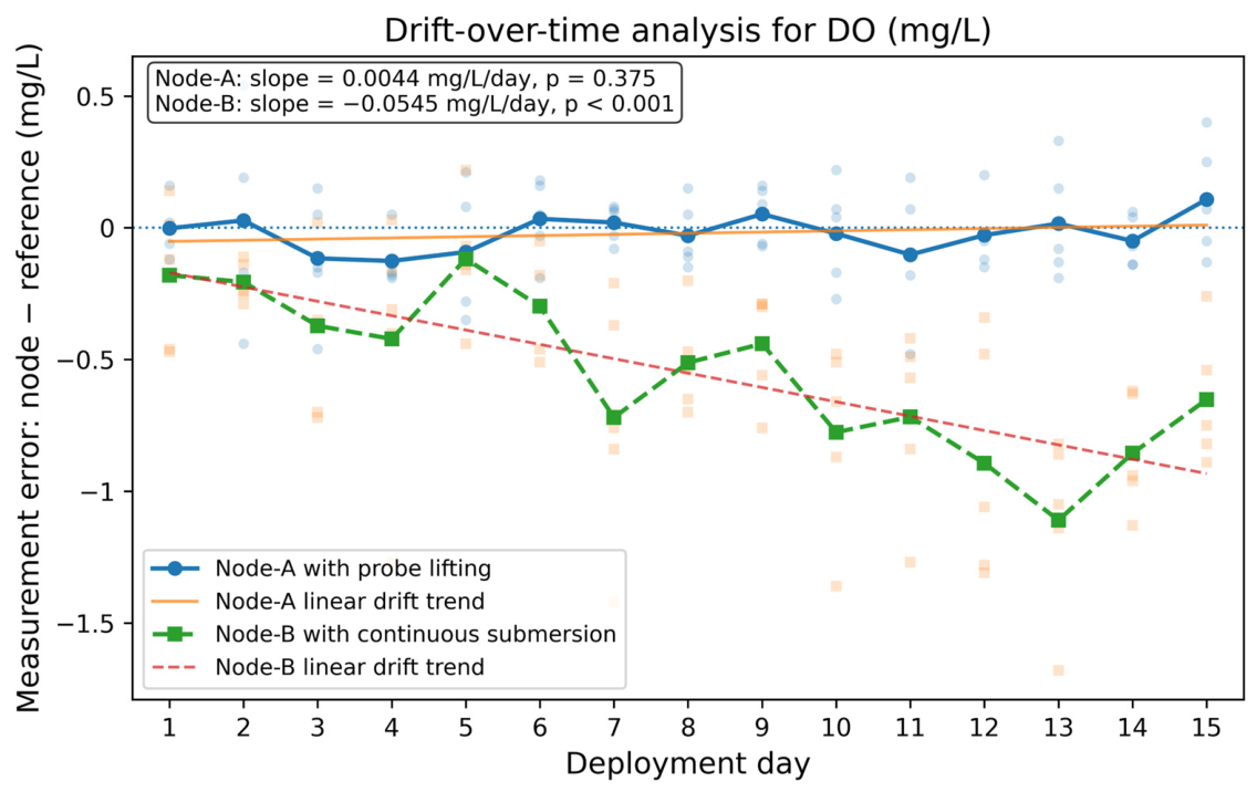
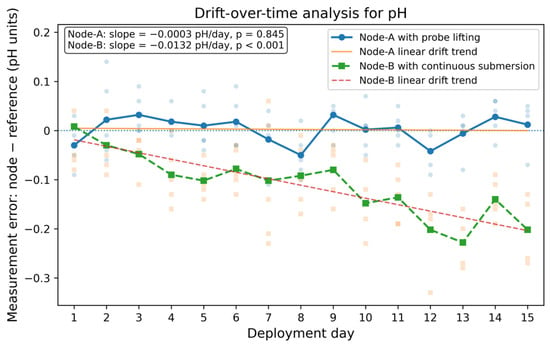
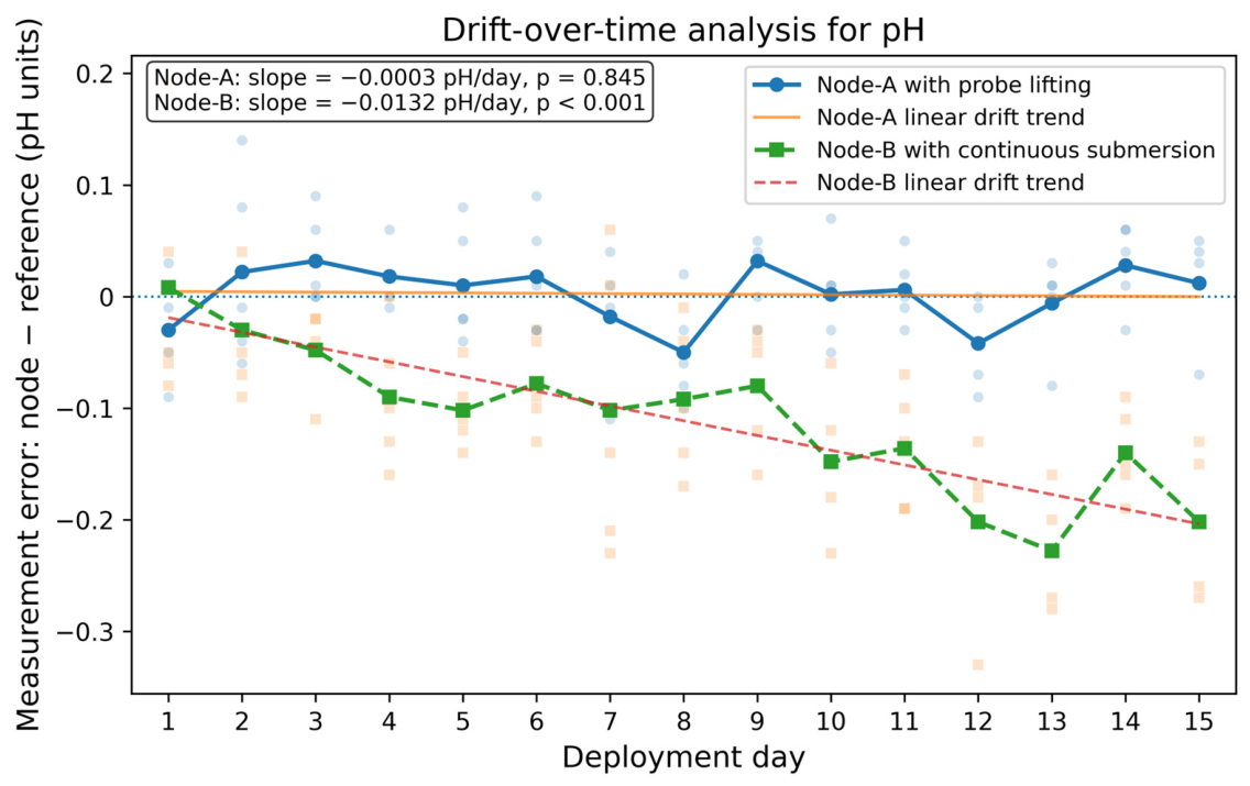
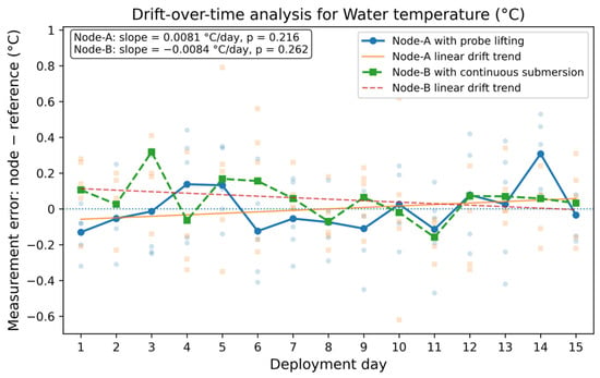
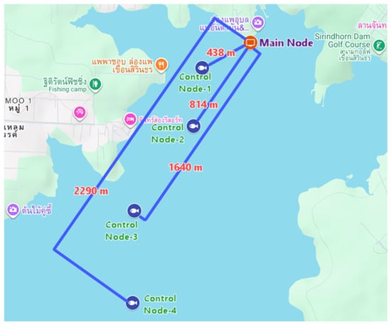
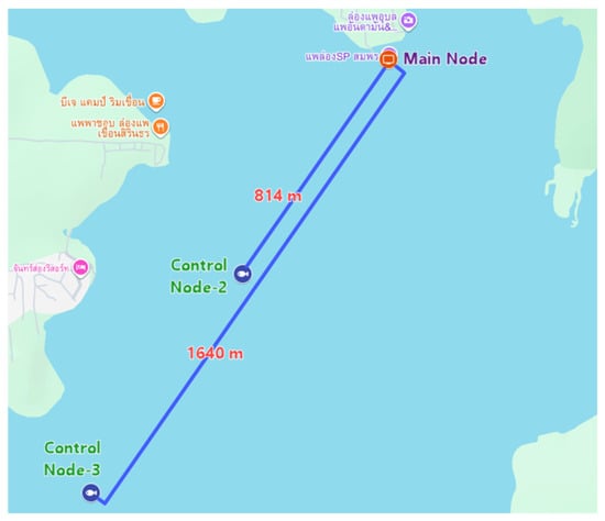
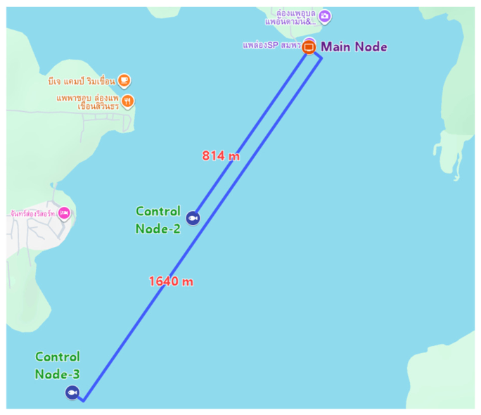
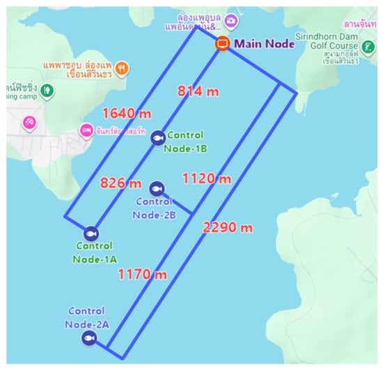
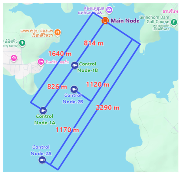

Disclaimer/Publisher’s Note: The statements, opinions and data contained in all publications are solely those of the individual author(s) and contributor(s) and not of MDPI and/or the editor(s). MDPI and/or the editor(s) disclaim responsibility for any injury to people or property resulting from any ideas, methods, instructions or products referred to in the content. |
© 2026 by the authors. Licensee MDPI, Basel, Switzerland. This article is an open access article distributed under the terms and conditions of the Creative Commons Attribution (CC BY) license.