


Abstract
In order to improve the quality of the laser and shorten the optical path of the fast steering mirror (FSM) laser compensation system, this paper proposes a four-degrees-of-freedom (4-DOF) voice coil motor (VCM) with the function of reducing laser geometrical fluctuations. The feature of this paper is the combination of a DC brushed spindle motor and the proposed 4-DOF VCM. A diffuser is installed on the shaft of the DC brushed motor for suppressing the laser speckle. The proposed 4-DOF VCM is combined with a laboratory-designed mirror set, controlling the laser direction to compensate for laser fluctuations. The proposed actuator was designed and verified by using the commercial CAD software SolidWorks and finite element analysis (FEA) software ANSYS. A mathematical model was built to simulate the dynamic response of the proposed 4-DOF VCM in MATLAB Simulink.
1. Introduction
Lasers are widely used in numerous fields, such as manufacturing, precision measurement, and even cosmetic surgery. The global demand of lasers has increased year by year and manufacturers’ requirements of laser quality have also grown. The laser seems to be stable when observed by naked eyes for a short period of time, but long-term measurement through the sensor reveals that the laser spot will be disturbed over time [1]. The stability of the laser changes with the environment and time, resulting in a total of four-degrees-of-freedom (4-DOF) fluctuations, including two translational fluctuations and two angular fluctuations. The causes of fluctuations include external temperature, air flow, vibration, laser power and laser wavelength stability, and so on [2,3,4,5].
The fast steering mirror (FSM) laser compensation system is one of the most common active compensation systems on the market [6,7,8,9,10]. FSM is mainly composed of a mirror, flexure structures, and actuators [11,12,13,14]. In the process of compensation, the system first measures fluctuations through the sensors, and then controls the actuators to drive the mirror, changing the laser direction to complete the laser compensation. The voice coil motor (VCM) is the most common actuator in FSMs. VCM has the advantages of low cost, simple structure, and fast response. Due to these advantages, VCM is also widely used in camera modules and hard disks [15,16]. Multiple DOF motions could be achieved with different configurations of VCMs [17,18,19,20]. However, to the best of our knowledge, the commercial FSM has only 2-DOF, driving the mirror and steering the laser in rotational motion along the X and Y axes [21]. Therefore, the commercial FSM laser compensation system must have two sets of FSMs to fully compensate laser 4-DOF fluctuations. Hence, the optical path will be longer, and this part is what we want to improve. According to our previous studies, we have presented a new FSM compensation system with double Porro prisms to compensate for the 4 DOF laser errors of the laser source, which is chacterized by shorter optical path length, fewer elements, and easier setup at different locations [22,23]. In this paper, we aim to design a new compact 4-DOF actuator to implement the idea of FSM based on double Porro prisms, and to integrate all parts in a very compact configuration.
In addition to laser fluctuations, laser speckle also reduces the quality of the laser. Laser speckle is mainly caused by coherence and scattering of the laser. For suppressing laser speckle, scholars use deformable mirror, deformable lens, and liquid crystals, etc., to improve the randomness of light scattering and reflection to equalize the light intensity [24,25,26]. Another way to suppress laser speckle is using a rotating diffuser. The rotating diffuser can make the laser spot more uniform because the particles in the diffuser rotate with it and make the situation of laser light scattering change over time. According to our previous studies, laser speckle from a laser light source (Edmund #83–838, 635 nm, Barrington, NJ, USA) can be effectively suppressed when the rotating speed of the diffuser reaches 2000 rpm [27,28,29].
Based on the above advance, in this paper, we aim to design a 4-DOF VCM, which is combined with a specific mirror set to suppress laser 4-DOF fluctuations and shorten the optical path of the FSM laser compensation system [22,23]. Additionally, we integrated the proposed 4-DOF VCM with a rotating diffuser (2000 rpm) to suppress the laser speckle by using a DC brushed spindle motor [27,28,29]. The detailed design goals are illustrated in Section 2.1.
2. Design Goals and Structure of Proposed Actuator
2.1. Design Goals
The common commercial 2-DOF FSM is composed of VCMs and spring plates, which have the advantages of high dynamic performance and simple/compact structure characteristics [22]. In order to integrate the function of suppressing the laser speckle, a conventional FSM laser compensation system must have two sets of VCMs and a spindle motor (three actuators) to fully compensate the laser’s 4-DOF errors. It is not easy to reduce the overall size, and the cost cannot be reduced. Therefore, this paper continues to use the simple structure characteristics of VCMs to design the proposed actuator. The design of the proposed actuator includes a 4-DOF VCM and a DC brushed motor, and cooperates with our special mirror group to reduce the number of actuators. The focus of the proposed design is to integrate the DC brushed motor with the rotating diffuser into the 4-DOF VCM and share the magnets to reduce the optical path and reduce the overall volume of the system. Here, the DC brushed motor uses commercially available parts, so each part’s size of the proposed actuator is designed based on the sizes of commercially available parts. It is noted that the shape and geometry of the proposed actuator are not particularly limited. The proposed actuator is designed with a square structure because it is convenient for design, production, and installation.
Based on previous research [27,28,29], the problems of laser speckle from a laser light source can be significantly improved when the laser passes through the diffuser with a rotational speed above 2000 rpm. Therefore, the minimum speed of the DC brushed motor is set to 2000 rpm. Referring to the specifications of the commercial 2-DOF FSM (FSM-300-01, Newport), the travel range of the rotational VCM is set to ±1.5° (±26.2 mrad) [21]. Considering the assembly tolerance, the laser fluctuation range [1] and the VCM must have a stable output performance when moving, setting the travel range of the translational VCM to ±0.05 mm, which is greater than that of the actuator developed in our previous study [22]. The above-mentioned design goals are listed in Table 1.
Table 1.
Design goals of proposed actuator.
2.2. Structure
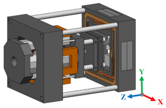
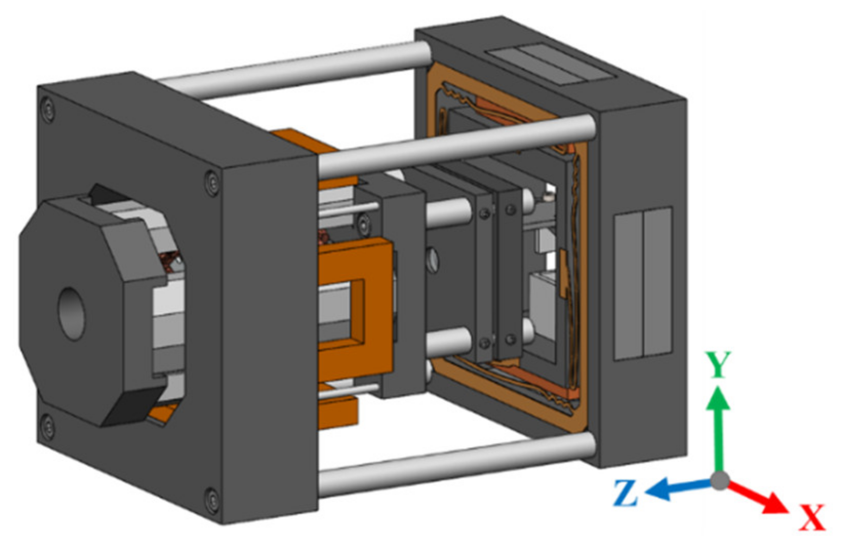
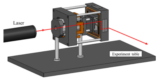
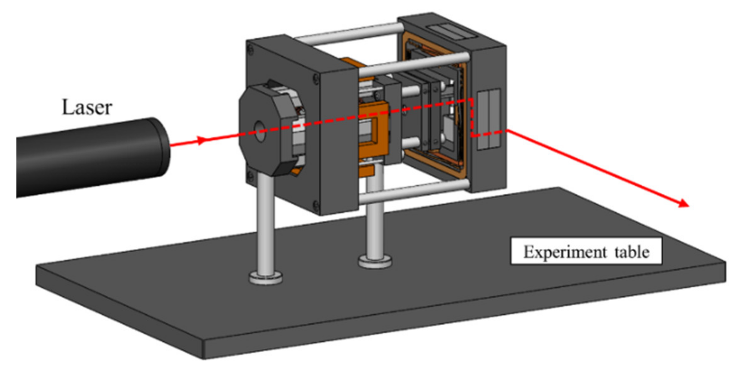
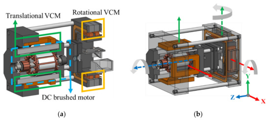
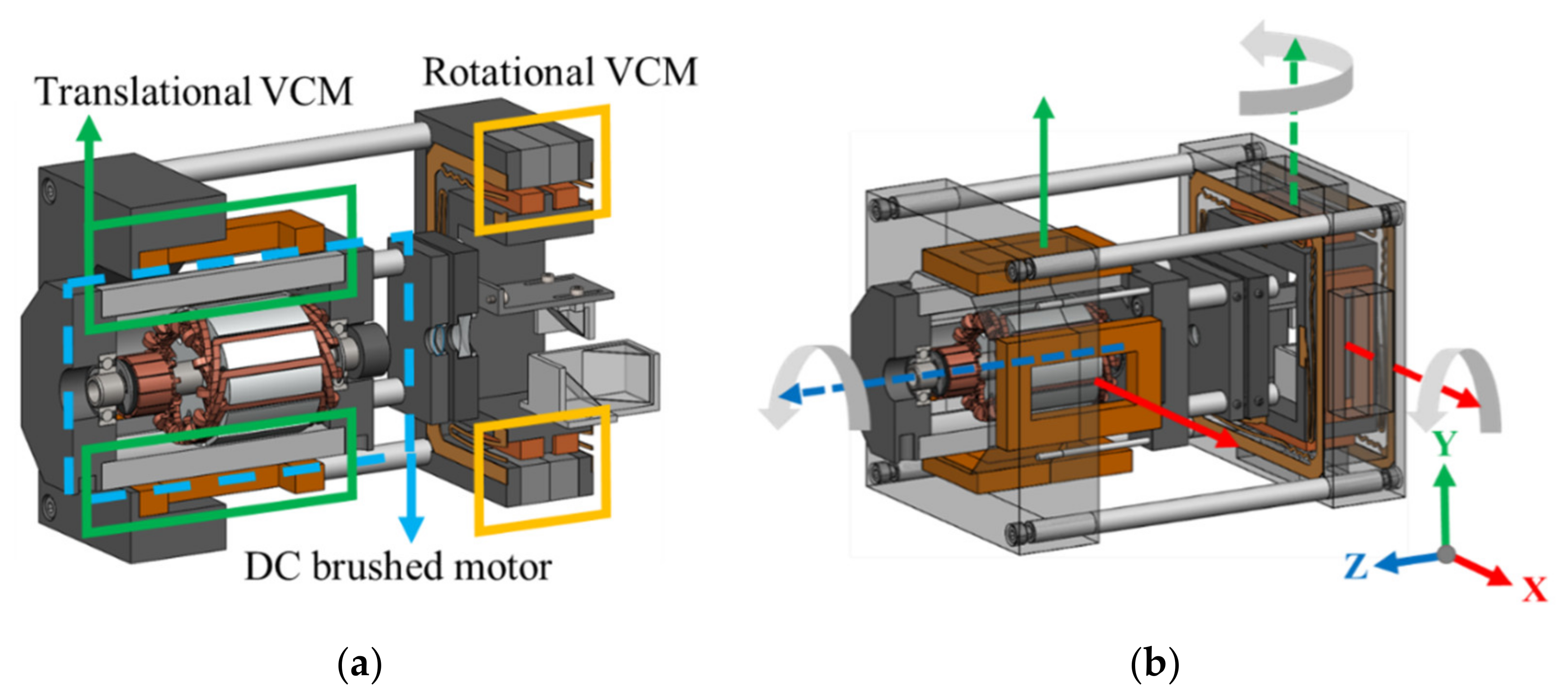
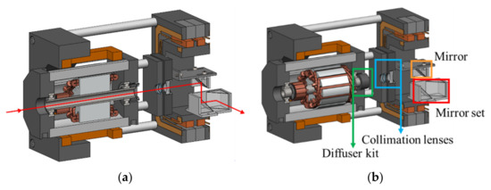
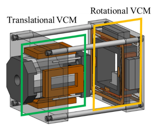
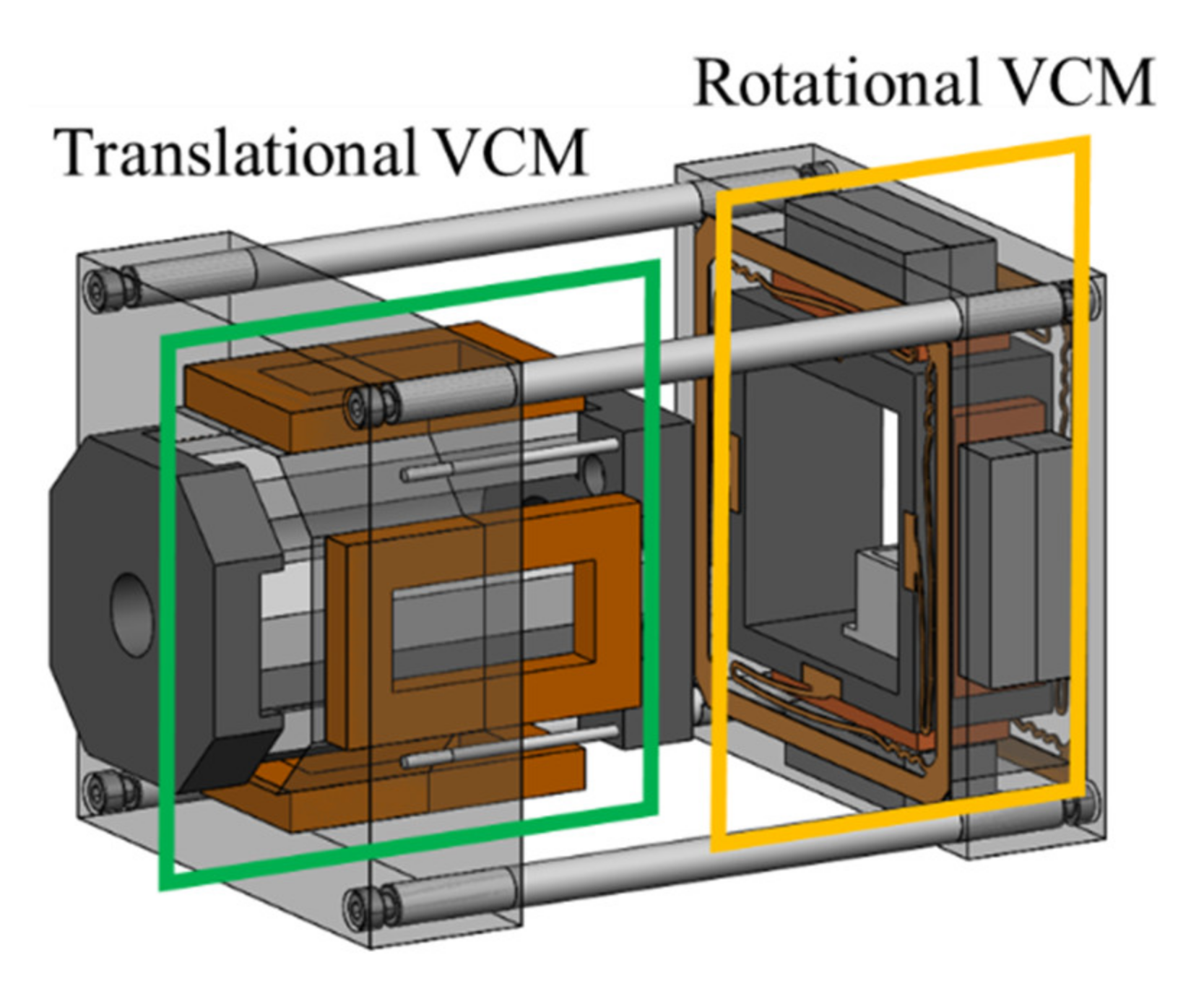
Figure 1 shows the structure of the proposed actuator. It is mainly composed of three parts, including a translational VCM, a rotational VCM, and a DC brushed motor. Figure 2 shows the schematic diagram of the experimental setup and the optical path of the laser. The proposed actuator is installed on the experiment table by using two pedestal posts. As shown in Figure 3a, the DC brushed motor is arranged inside the translational VCM and shares the magnets with it. The shaft of the DC brushed motor is hollow, and a diffuser is installed at the end of it. Motions of the proposed actuator are shown in Figure 3b. The internal DC brushed motor drives the diffuser to continuously rotate in the Z-axis direction. The external VCM has total of 4-DOF, including translational movements in X- and Y-axis directions and rotational movements along X- and Y-axis directions.
Figure 1.
Structure of proposed actuator.
Figure 2.
Setup of proposed actuator.
Figure 3.
(a) Main composition of the proposed actuator, and (b) schematic diagram of motions.
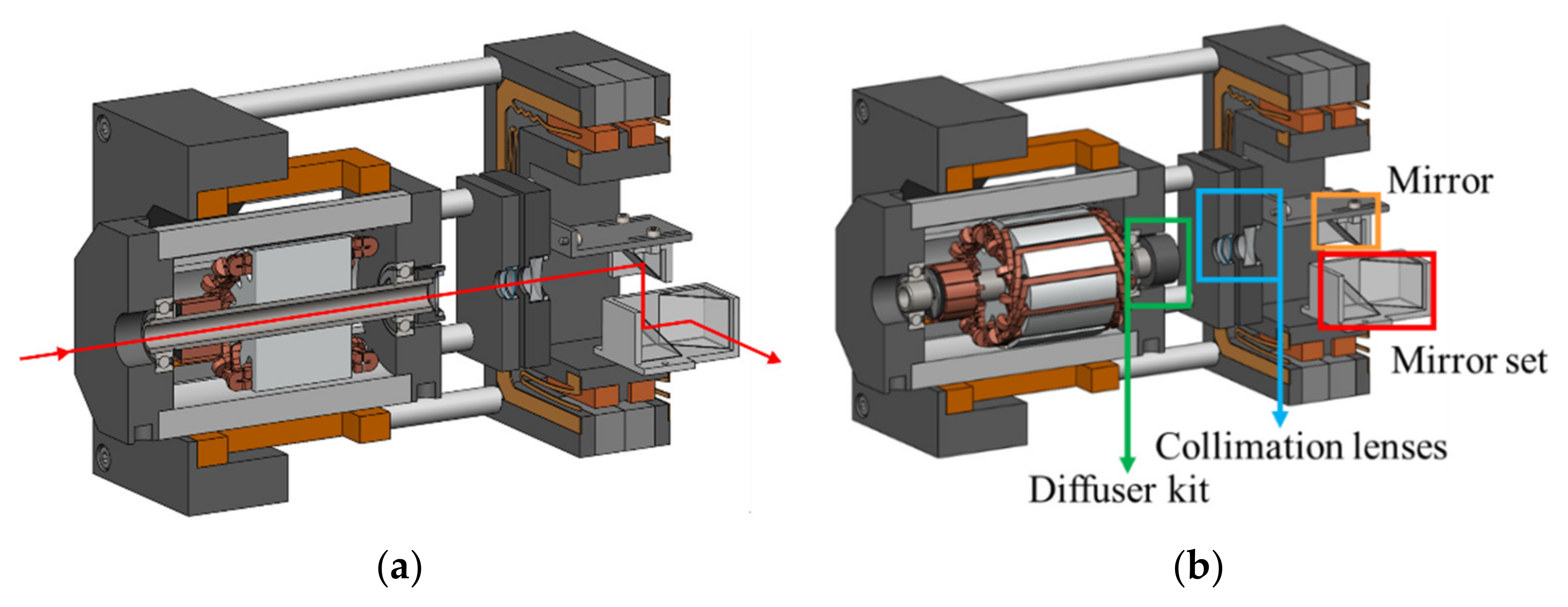
The detailed optical path is shown in Figure 4a. Laser beam diameter is enlarged after the laser passes through the hollow shaft and the diffuser. Therefore, lenses are installed behind the DC brushed motor for laser collimation, as shown in Figure 4b. After the collimation, a mirror is utilized for guiding the laser into the mirror set. The mirror set is installed inside the rotational VCM. The proposed 4-DOF VCM drives the mirror set to change the laser direction and compensate for laser 4-DOF fluctuations, and the DC brushed motor and translational VCM use a shared permanent magnet design to shorten the overall optical path, decrease system space, and reduce costs. The detailed structure and operating principle of the proposed 4-DOF VCM will be explained in subsequent sections.
Figure 4.
(a) Schematic diagram of the optical path, and (b) optical elements in the proposed actuator.
3. Design and Simulation of DC Brushed Motor
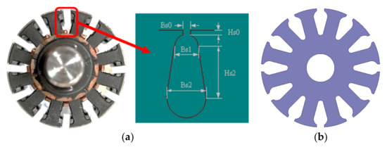
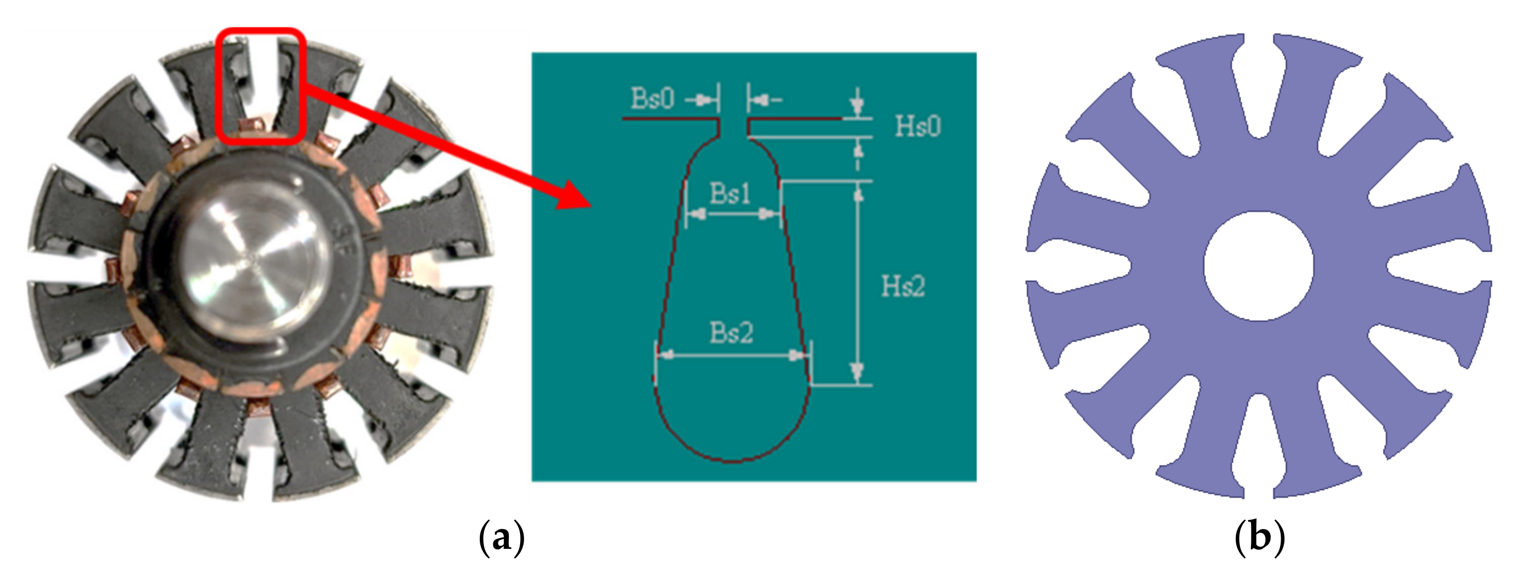
For reducing the processing difficulty, design time, and cost, the DC brushed motor in this paper uses parts from a commercial product, including commutator and silicon steel sheets of a motor. The original magnets’ configuration and coil windings are changed. Additionally, the motor shaft is changed to a hollow one for letting the laser pass through. The DC brushed motor in this paper has 4 poles and 12 slots. The symbols and dimensions of silicon steel sheets of the rotor are shown in Figure 5 and Table 2.
Figure 5.
The rotor of the DC brushed motor: (a) symbols of slot and (b) 2D model of silicon steel sheet.
Table 2.
Dimensions of silicon steel sheets of the rotor.
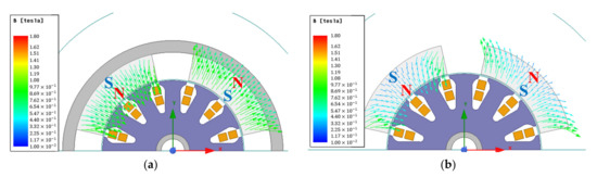
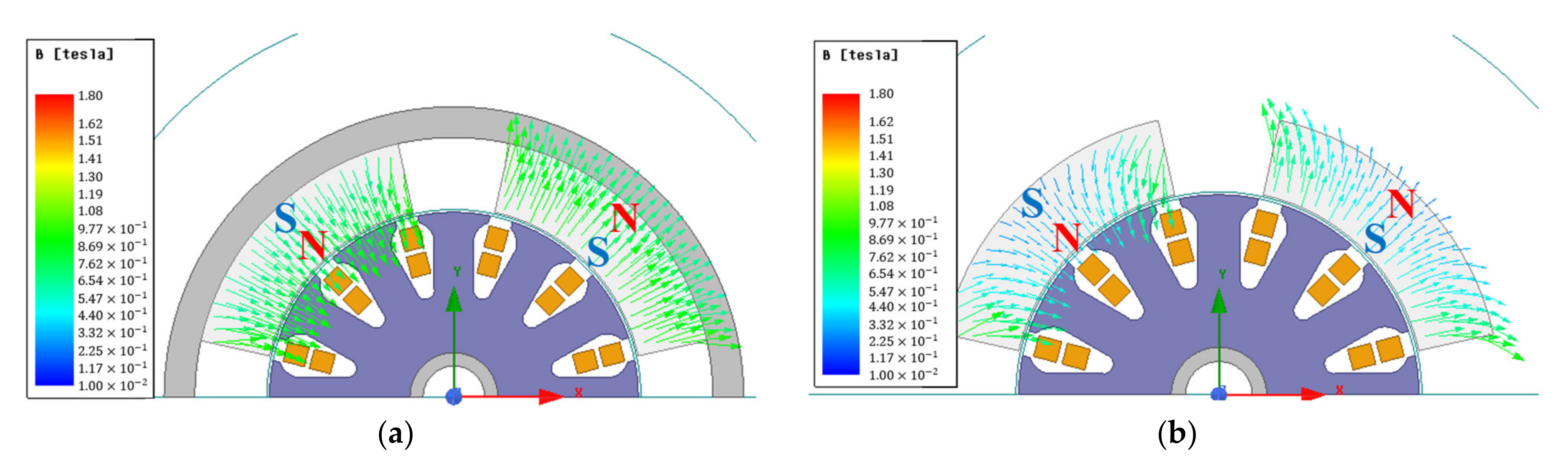
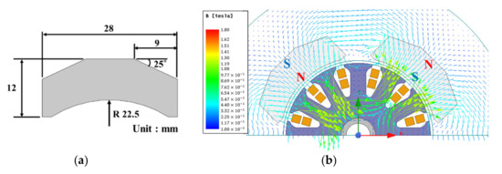
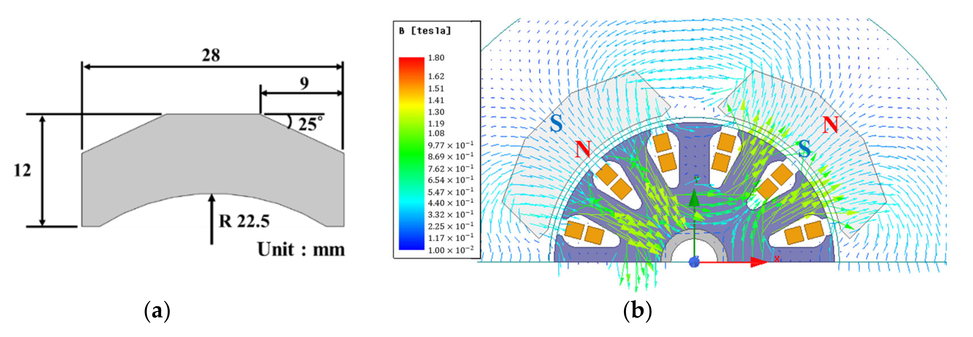
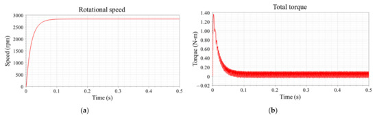
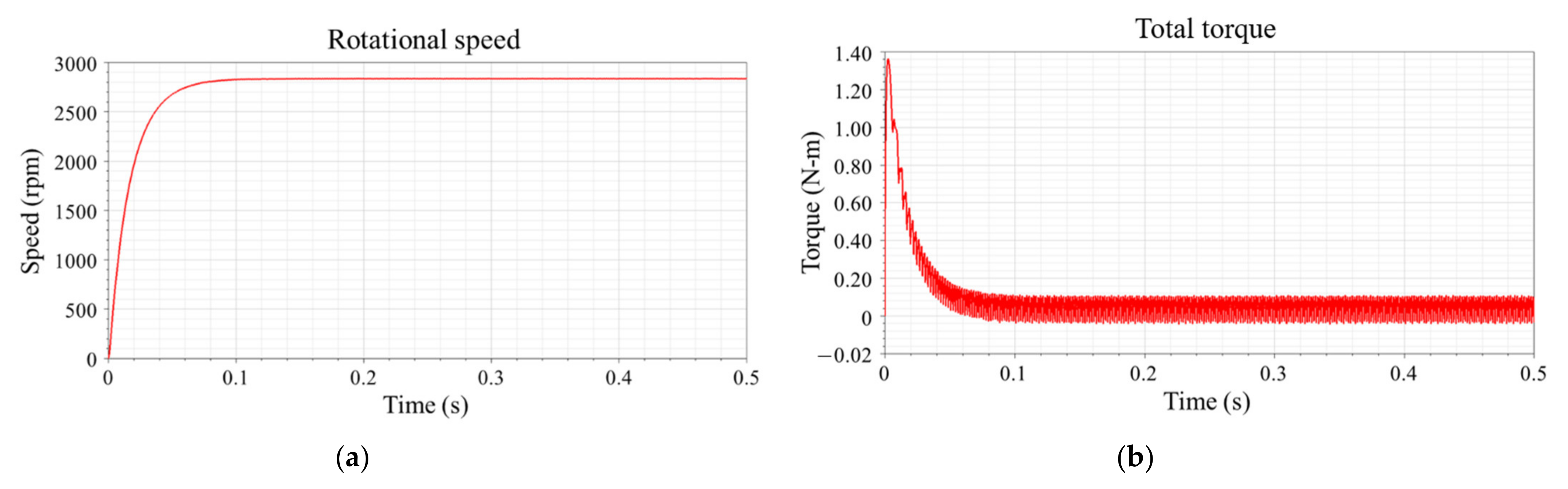
In most of the commercial DC brushed motors, magnets are installed on a magnetic shell for guiding magnetic flux and providing a uniform magnetic field for the rotor. In this paper, because the DC brushed motor shares the magnets with the external translational VCM, there is no outer shell. The magnetic flux of the motor becomes more non-uniform without a magnetic shell, as shown in Figure 6. Figure 6b shows that the magnetic field at the tip of the magnets is relatively stronger. A non-uniform magnetic field will cause the motor to operate un-smoothly. For obtaining a more uniform magnetic field, the shape of magnets is changed by doing chamfers, as shown in Figure 7a. Figure 7b shows the magnetic flux distributions after the magnet shape is changed. The magnet material of the DC brushed motor in this paper is Ndfe50. Compared to Figure 6b, the magnetic field at the corners of magnets is relatively uniform. There are 12 slots of the rotor, and the coil winding type is lap winding. There are 12 sets of coils, and each set is composed of 30 turns of the coil. The detailed coil winding parameters are listed in Table 3. The material of the shaft is Steel 1008, and the inner diameter is 7 mm. The moment of inertia of the rotor is kg m2 obtained by using SolidWorks. The finite element analysis (FEA) simulation results of 12 V input are shown in Figure 8. The motor reached a stable speed of 2835 rpm in 0.15 s after starting and reached design target of 2000 rpm. At a stable speed, the average torque of the motor is 0.052 N-m.
Figure 6.
Magnetic flux distributions of DC brushed motor: (a) with magnetic shell and (b) without magnetic shell.
Figure 7.
DC brushed motor in the proposed actuator: (a) dimensions of the magnet and (b) magnetic flux distributions.
Table 3.
Coil winding parameters of the DC brushed motor.
Figure 8.
Simulation results of the DC brushed motor: (a) rotational speed and (b) total torque.
4. Design and Simulation of 4-DOF VCM
In this section, the detailed structure and simulation results of the proposed 4-DOF VCM will be introduced. For the convenience of explanation, the models in this section only show the 4-DOF VCM temporarily.
4.1. Structure and Working Principle of 4-DOF VCM
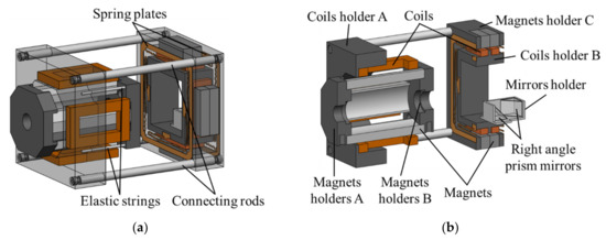
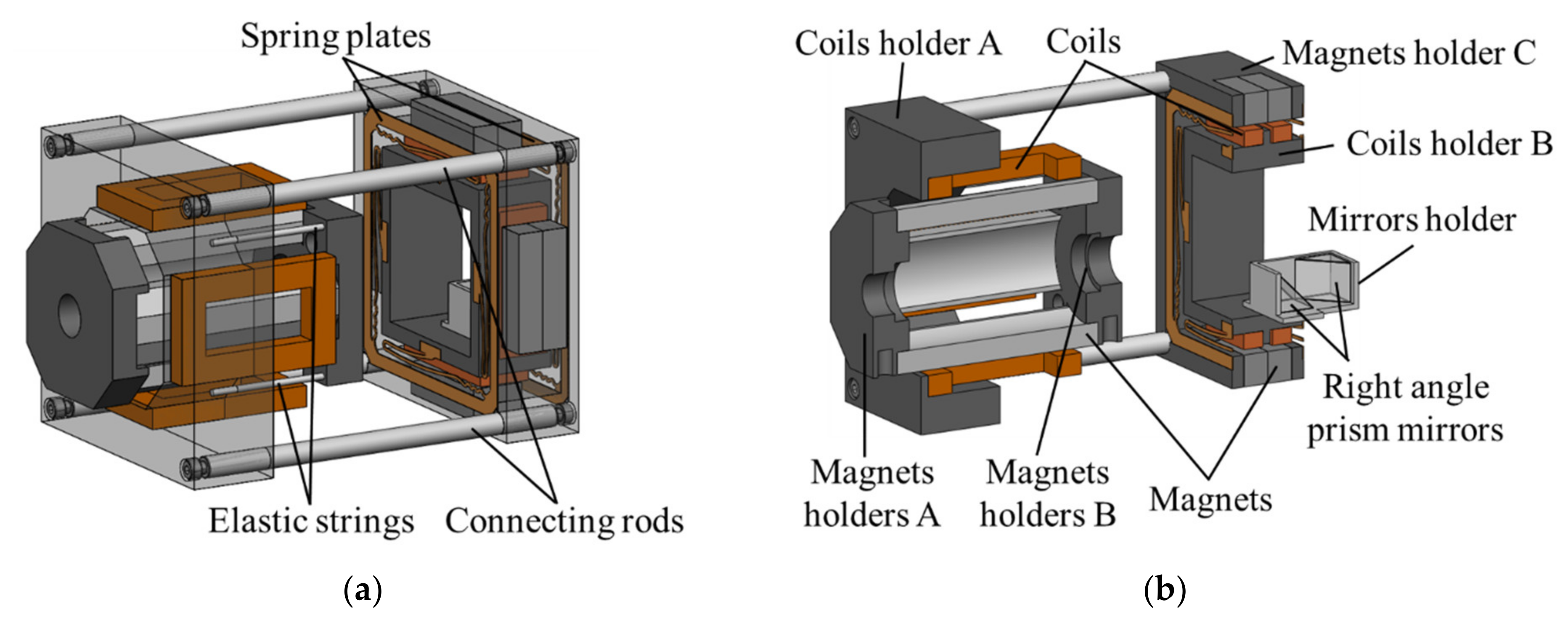
The 4-DOF VCM includes two parts: the translational VCM and the rotational VCM, as shown in Figure 9. The translational VCM is composed of 4 coils and 4 magnets, which are shared with the inside DC brushed motor. Coils are moving parts and magnets are stationary parts, respectively. The coils are installed on the coil holder A, and connected to the magnet holder B by 4 elastic strings. The rotational VCM is composed of 4 coils and 4 sets of magnets. The coils and mirror set are installed on the coil holder B and connected to the magnet holder C by 2 spring plates. The translational VCM and rotational VCM are assembled by using 4 connecting rods and screws. When the translational VCM is actuated, the rotational VCM and mirror set could move simultaneously. The components of the 4-DOF VCM are shown in Figure 10.
Figure 9.
3D model of the 4-DOF VCM.
Figure 10.
4-DOF VCM 3D model: (a) connecting parts and (b) section view.
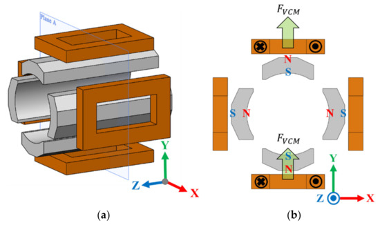
Figure 11a only shows the coils and magnets of the translational VCM. Figure 11b is the section view obtained from Figure 11a. According to the directions of current and magnetization of permanent magnets in Figure 11b, the coils will generate upward force, FVCM, individually, causing a displacement in the Y-axis direction. When the power is cut off, the moving part will return to its initial position due to the restoring force of elastic strings.
Figure 11.
Translational VCM: (a) schematic diagram of section view and (b) working principle.
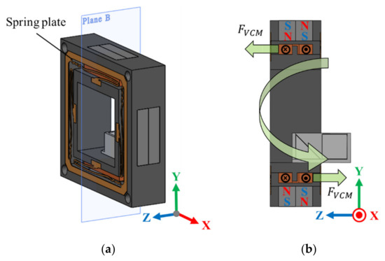
The rotational VCM shown in Figure 12a,b is the section view obtained from Figure 12a. Directions of current and magnetization of permanent magnets are shown in Figure 12b. According to the right-hand rule, the upper coil will generate a force, FVCM, in the positive Z-axis direction. On the contrary, the lower coil will generate a force, FVCM, in the negative Z-axis direction. Coil holder B rotates on an angle along the positive X-axis direction due to the opposite forces. The restoring force of spring plates will make the part move back to its initial position when the power is shut down.
Figure 12.
Rotational VCM: (a) schematic diagram of section view and (b) working principle.
4.2. Mathematical Modeling
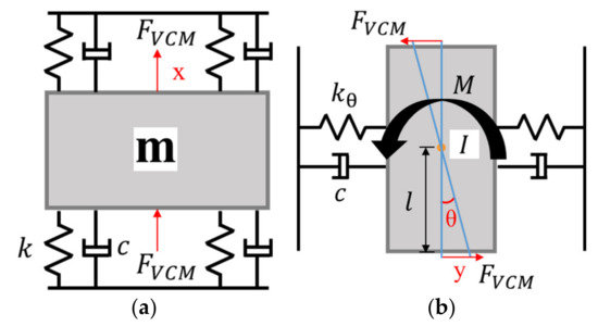
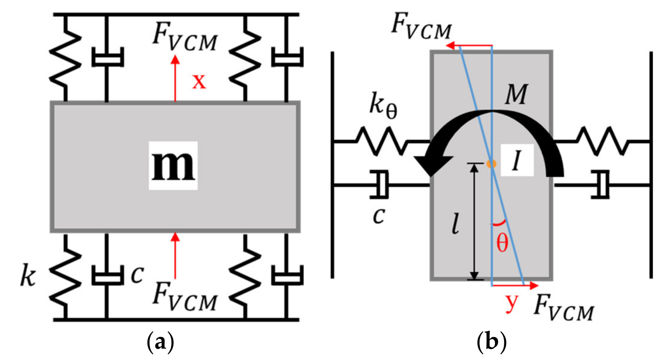
It is necessary to establish mathematical models for preliminary evaluation of the performance of the proposed VCM. In the proposed actuator, the VCM has a total 4-DOF motions. Assuming translational and rotational motions of the proposed 4-DOF VCM are ideal and independent of each, schematic models of the proposed 4-DOF VCM could be simplified as Figure 13a,b.
Figure 13.
Schematic model of the proposed 4-DOF VCM: (a) translational VCM and (b) rotational VCM.
Figure 13a illustrates the simplified ideal model of the translational VCM. In the translational VCM, the moving part and the stationary part are connected by 4 elastic strings. In Figure 13a, m denotes the mass of the moving part, k denotes the stiffness of elastic strings, and c denotes the damping coefficient of the translational VCM. According to Kirchhoff’s circuit laws, the electrical equation of the translational VCM could be expressed as follows:
where V, i, R, and L are the input voltage, input current, resistance, and inductance of the translational VCM, respectively. Based on Newton’s second law and Hook’s law, the dynamic equation of the translational VCM could be expressed as follows:
where 2FVCM is the Lorentz force generated by VCMs on both sides, x means the displacement, and a is the acceleration of the moving part. Equation (3) is obtained from Equation (2). In Equation (3), 2FVCM is replaced by 2KVCMi(t), and 2KVCM denotes the motor coefficient of the translational VCM. After the Laplace transform and organizing of Equations (1) and (3), the transfer function of the translational VCM could be expressed as follows:
Figure 13b is the schematic model of the rotational VCM. The moving part and the stationary part are connected by 2 spring plates. In Figure 13b, I denotes the moment of inertia of the moving part, kθ denotes the stiffness of spring plates, θ denotes the rotational angle, c denotes the damping coefficient, and l denotes the distance between the coil and the center of the rotational VCM. According to the torque formula, the dynamic equation of the rotational VCM could be expressed as:
where M is the torque generated by VCMs on both sides, and α denotes the angular acceleration. Since the rotational angle θ is quite small, the approximation of tanθ ≅ θ is utilized in Equation (5). Equation (6) is obtained from Equation (5). In Equation (6), the torque, M, is replaced by 2 × KVCMi(t)l, and KVCM denotes the motor coefficient of the rotational VCM. After the Laplace transform and organizing of Equation (6) and the electrical equation, the transfer function of the rotational VCM could be expressed as:
4.3. Simulation of Electromagnetic and Mechanical Structure
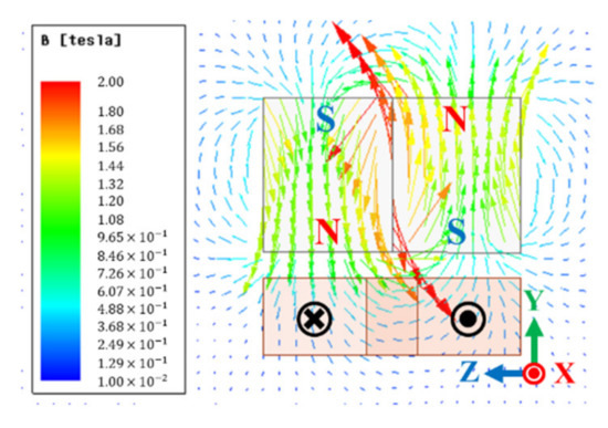
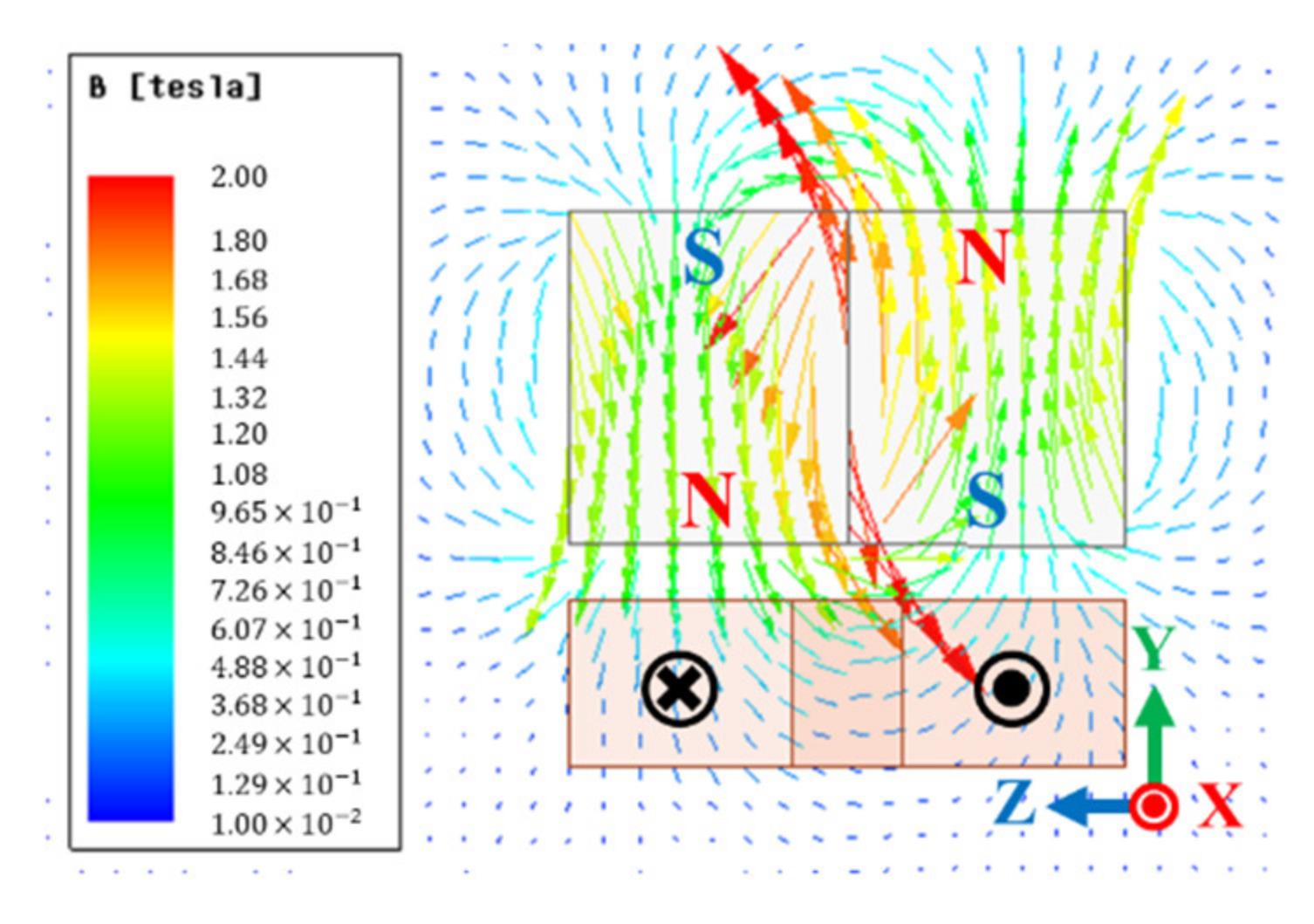
After the mathematical modeling, the FEA software ANSYS Maxwell was used to simulate the motor constants of VCMs. The material of all magnets was Ndfe50 in the proposed actuator. The translational VCM is composed of 4 magnets and 4 coils. Coils in the same axis direction are connected in series and are actuated in pairs.
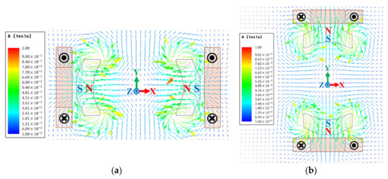
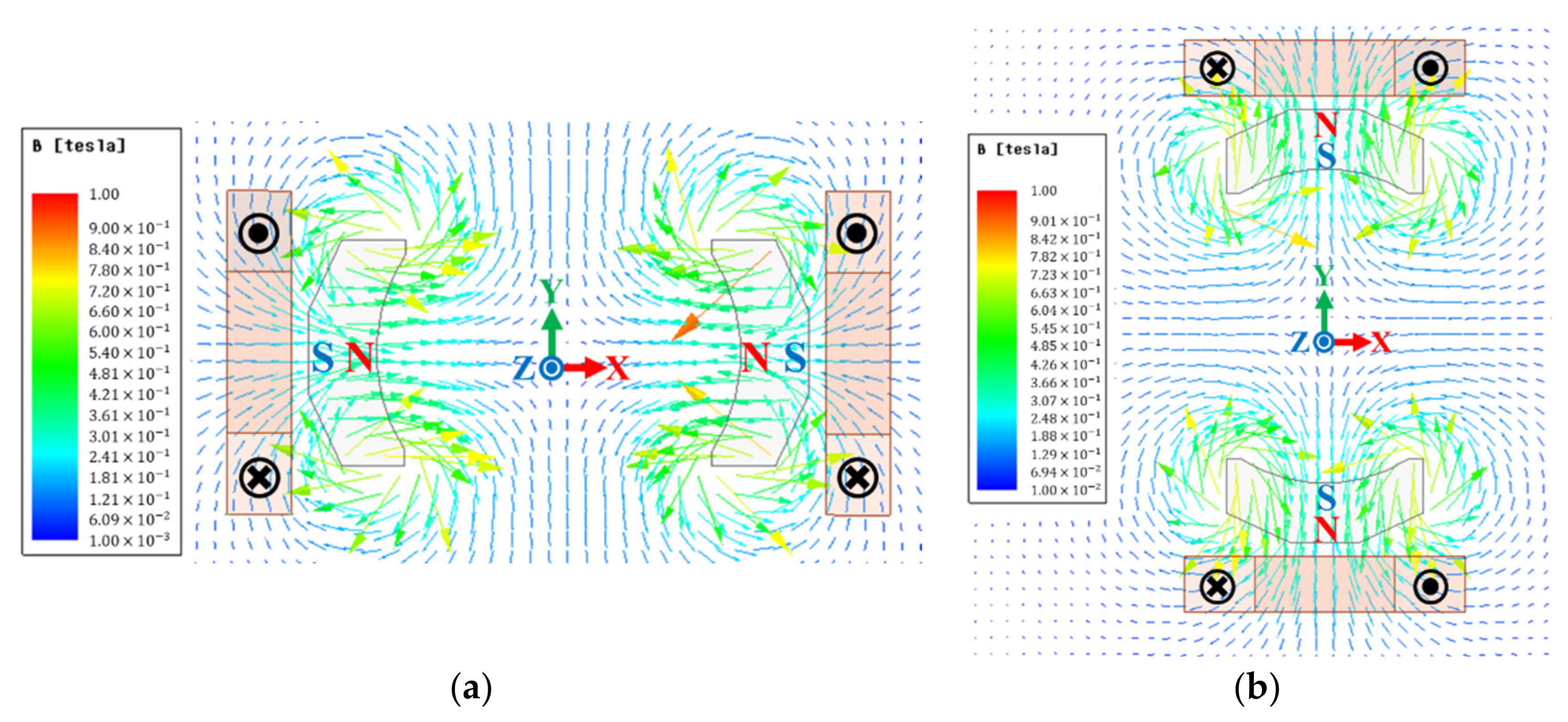
Figure 14 shows the magnetic flux distributions of the translational VCM. The magnets in the X-axis direction are magnetized radially inward, and the magnets in the Y-axis direction are magnetized radially outward. Within displacement of ±0.05 mm, the average motor constant of the translational VCM 2KVCM ≅ 10.3 N/A. The rotational VCM consists of 4 coils and 4 sets of magnets. Figure 15 only shows one pair of them. The simulation results show that the average motor constant of the rotational VCM KVCM ≅ 4.36 N/A, within the rotational angle of ±1.5°. Table 4 shows the design parameters of the proposed electromagnetic structure.
Figure 14.
Magnetic flux of translational VCM: (a) in X-axis direction and (b) in Y-axis direction.
Figure 15.
Magnetic flux of rotational VCM.
Table 4.
Design parameters of electromagnetic structure.
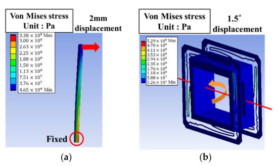
To ensure that the connecting parts of the VCM will not undergo plastic deformation, the FEA software ANSYS was used to simulate the stress of the elastic string and the spring plate under the maximum displacement. The material of elastic strings is Ti-6Al-4V, and the spring plate is C17200 copper. In the translational VCM, the distance between the coil and magnet is 2 mm, which means that the maximum displacement of the elastic string is 2 mm. The maximum stress of the elastic string under 2 mm displacement is 338 MPa, as shown in Figure 16a. Figure 16b shows the simulation result of spring plates under a 1.5° rotational angle. The maximum stress of spring plates is 528.8 MPa. Through simulations, it is known that the stress of elastic strings and spring plates under the maximum displacement is less than the yield strength of the material, and no plastic deformation occurs. The relevant material parameters and dimensions are shown in Table 5.
Figure 16.
Von Mises stress of connecting parts: (a) elastic string and (b) spring plates.
Table 5.
Design parameters of the mechanical structure.
4.4. Dynamic Response Simulation
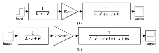
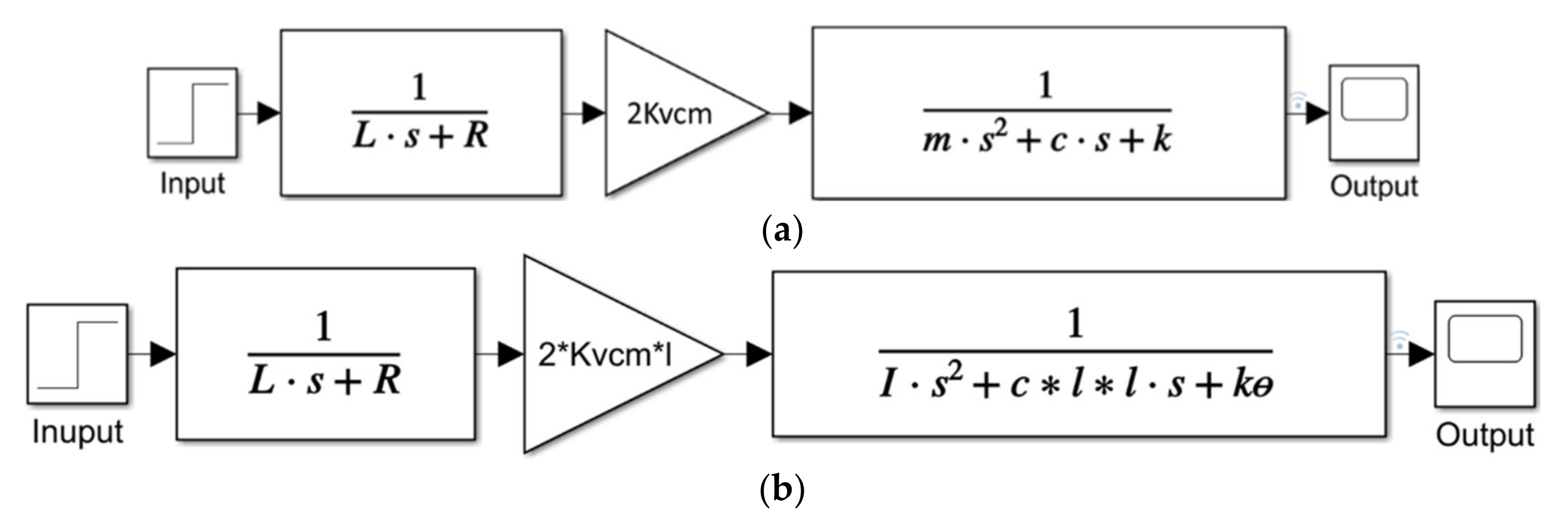
In this section, MATLAB Simulink was used for step response simulations. The transfer functions of the translational VCM and rotational VCM, Equations (4) and (7), were built by using block diagrams. Models in MATLAB Simulink are shown in Figure 17. The modeling parameters of the proposed 4-DOF VCM are listed in Table 6. In Table 6, the spring constant, k, is obtained by simulating the ratio of a given load to displacement in ANSYS mechanical, and the damping ratio, c, is set based on a previous study [22]. There is also a method for calculating the damping characteristics of rigid materials used in finite element calculations [30]. In the translational VCM model and the rotational VCM, the input parameter is voltage, and the output parameters are displacement and rotational angle, respectively.
Figure 17.
Mathematical models in MATLAB Simulink: (a) translational VCM and (b) rotational VCM.
Table 6.
Design parameters of the mechanical structure.
During the step input response simulations, the time it takes for the proposed VCM moving from 10% to 90% of the target displacement is called the rise time. In the process of moving to the target position, the proposed VCM will oscillate back and forth for a while due to elastic strings, spring plates, and system damping, before it gradually stabilizes. The time it takes from driving to when the oscillation range is less than ±2% of the target position error is called the settling time.
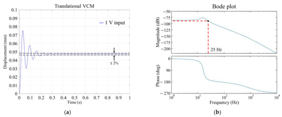
The 1 V step input response simulation result of the translational VCM is shown in Figure 18a. The translational VCM produces a displacement around 0.047 mm under an input voltage of 1 V. The rise time is about 12 ms, and the settling time is approximately 230 ms. When the input voltage is about 1.05 V, the translational VCM can reach the target displacement of 0.05 mm. The open loop Bode plot of the translational VCM is shown in Figure 18b and its bandwidth is 25 Hz.
Figure 18.
Translational VCM: (a) 1 V step input response and (b) open loop Bode plot.
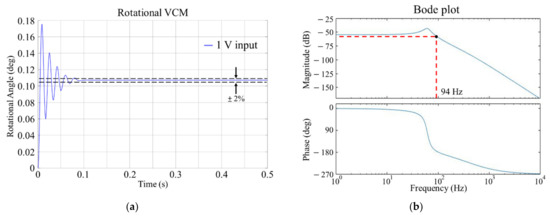
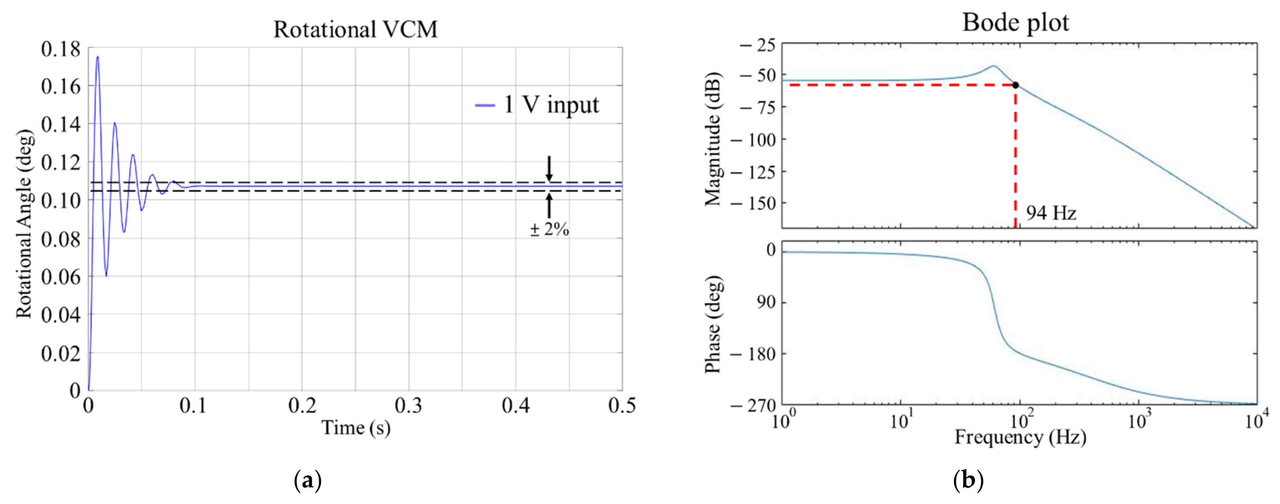
Figure 19a shows the 1 V step input response simulation result of the rotational VCM. Under an input of 1 V, the rotational VCM produces a rotational angle around 0.11°. The rise time is about 4 ms, and the settling time is approximately 82 ms. When the input voltage is about 15 V, the rotation angle reaches the design goal of 1.5°. Figure 19b shows the Bode plot of the rotational VCM, and the figure shows that the bandwidth of the rotational VCM is 94 Hz. The above-mentioned Bode plots were generated by inputting transfer functions in MATLAB. The prototype of the proposed actuator will be manufactured after the optimization and establishment of a complete closed loop control system in the future. Table 7 compares the performance of the proposed actuators in this paper and our previous study [22]. The proposed actuator in this paper has a higher DOF (with a rotating movement (2000 rpm)), and both the translational VCM and the rotational VAM have larger movement strokes. Only the simulation of the open loop control was used in this paper. From the simulation results, the rotating VCM has a much higher bandwidth. In future works, the signal output to the 4-DOF VCM can be controlled at any time with the sensor to measure the disturbance amount for closed loop control, which may further improve the motor’s bandwidth and dynamic response.
Figure 19.
Rotational VCM: (a) 1 V step input response and (b) open loop Bode plot.
Table 7.
Performance comparison of the proposed actuator and the actuators developed in [22].
5. Conclusions
In this paper, a 4-DOF VCM with the function of reducing laser geometric fluctuations was first proposed. A DC brushed motor was integrated into the proposed 4-DOF VCM. While the proposed 4-DOF VCM drives the mirror set to compensate laser fluctuations, the internal DC brushed motor drives the diffuser, suppressing laser speckle simultaneously. The optical path was shortened, and the laser quality can be improved. Under 12 V constant voltage input, the speed of the DC brushed motor can reach 2835 rpm, reaching the design goal of 2000 rpm. The translational VCM and the rotational VCM can reach target displacement of 0.05 mm and a rotational angle of 1.5° when the input voltages are 1.05 and 15 V, respectively. The open loop bandwidths of the translational VCM and rotational VCM are 25 and 94 Hz respectively. It is enough to reduce the long-term and slow laser disturbance of the laser, but it may still be slightly insufficient in the case of rapid and drastic changes. The proposed actuator was designed and verified by using the commercial CAD software SolidWorks and the FEA software ANSYS. A mathematical model was built to simulate the dynamic response of the proposed 4-DOF VCM in MATLAB Simulink. In the future, the design of this actuator will be optimized, and a laboratory prototype will be manufactured to evaluate its dynamic performance.
Author Contributions
Conceptualization, C.-S.L. and Y.-C.W.; methodology, C.-S.L. and Y.-C.W.; validation, Y.-C.W. and Y.-J.L.; investigation, C.-S.L. and Y.-C.W.; writing—original draft preparation, C.-S.L.; writing—review and editing, C.-S.L.; supervision, C.-S.L.; project administration, C.-S.L.; funding acquisition, C.-S.L. All authors have read and agreed to the published version of the manuscript.
Funding
This research was funded by the Ministry of Science and Technology of Taiwan, grant numbers MOST 110-2221-E-006-162-MY2 and MOST 105-2221-E-006-265-MY5.
Institutional Review Board Statement
Not applicable.
Informed Consent Statement
Not applicable.
Data Availability Statement
Not applicable.
Acknowledgments
Ansys Inc. is thanked for providing the ANSYS academic partner program.
Conflicts of Interest
The authors declare no conflict of interest.
References
- Kuo, C.-C.; Chao, C.-S. Characterization of probe lasers for thin-film optical measurements. J. Russ. Laser Res. 2010, 31, 22–31. [Google Scholar] [CrossRef] [Scilit]
- Kim, D.I.; Rhee, H.-G.; Song, J.-B.; Lee, Y.-W. Laser output power stabilization for direct laser writing system by using an acousto-optic modulator. Rev. Sci. Instrum. 2007, 78, 103110. [Google Scholar] [CrossRef] [Scilit] [PubMed]
- Tricot, F.; Phung, D.H.; Lours, M.; Guérandel, S.; De Clercq, E. Power stabilization of a diode laser with an acousto-optic modulator. Rev. Sci. Instrum. 2018, 89, 113112. [Google Scholar] [CrossRef] [Scilit]
- Lamour, T.P.; Sun, J.; Reid, D.T. Wavelength stabilization of a synchronously pumped optical parametric oscillator: Optimizing proportional-integral control. Rev. Sci. Instrum. 2010, 81, 053101. [Google Scholar] [CrossRef] [Scilit]
- Sugiarto, I.T.; Watanabe, M.; Sunada, S.; Hyodo, M. Frequency stabilization of dual-mode microchip laser by means of beat frequency stabilization. Opt. Rev. 2019, 27, 98–107. [Google Scholar] [CrossRef] [Scilit]
- Lu, Y.; Fan, D.; Zhang, Z. Theoretical and experimental determination of bandwidth for a two-axis fast steering mirror. Optik 2013, 124, 2443–2449. [Google Scholar] [CrossRef] [Scilit]
- Shinshi, T.; Shimizu, D.; Kodeki, K.; Fukushima, K. A Fast Steering Mirror Using a Compact Magnetic Suspension and Voice Coil Motors for Observation Satellites. Electronics 2020, 9, 1997. [Google Scholar] [CrossRef] [Scilit]
- Wang, D.; Watkins, C.; Koppal, S.; Xie, H. A silicon optical bench with vertically-oriented micromirrors for active beam steering. Sens. Actuators A Phys. 2019, 298, 111586. [Google Scholar] [CrossRef] [Scilit]
- Long, Y.; Mo, J.; Wei, X.; Wang, C.; Wang, S. Design of a Moving-magnet Electromagnetic Actuator for Fast Steering Mirror through Finite Element Simulation Method. J. Magn. 2014, 19, 300–308. [Google Scholar] [CrossRef] [Scilit]
- Long, Y.; Wang, C.; Dai, X.; Wei, X.; Wang, S. Modeling and analysis of a novel two-axis rotary electromagnetic actuator for fast steering mirror. J. Magn. 2014, 19, 130–139. [Google Scholar] [CrossRef] [Scilit]
- Riza, M.; Hao, G. A flexure motion stage system for light beam control. Microsyst. Technol. 2018, 25, 3185–3191. [Google Scholar] [CrossRef] [Scilit]
- Hao, G.; He, X. Designing a monolithic tip-tilt-piston flexure manipulator. Arch. Civ. Mech. Eng. 2017, 17, 871–879. [Google Scholar] [CrossRef] [Scilit]
- Lin, R.; Li, Y.; Zhang, Y.; Wang, T.; Wang, Z.; Song, Z.; Dou, Z.; Qian, J. Design of A flexure-based mixed-kinematic XY high-precision positioning platform with large range. Mech. Mach. Theory 2019, 142, 103609. [Google Scholar] [CrossRef] [Scilit]
- Liu, H.; Fan, S.; Xie, X.; Zhang, Z.; Fan, D. Design and modeling of a novel monolithic parallel XY stage with centimeters travel range. Adv. Mech. Eng. 2017, 9. [Google Scholar] [CrossRef] [Scilit]
- Hsieh, C.-L.; Liu, C.-S.; Cheng, C.-C. Design of a 5 degree of freedom–voice coil motor actuator for smartphone camera modules. Sens. Actuators A Phys. 2020, 309, 112014. [Google Scholar] [CrossRef] [Scilit]
- Liu, C.-S.; Lin, P.-D.; Lin, P.-H.; Ke, S.-S.; Chang, Y.-H.; Horng, J.-B. Design and Characterization of Miniature Auto-Focusing Voice Coil Motor Actuator for Cell Phone Camera Applications. IEEE Trans. Magn. 2009, 45, 155–159. [Google Scholar] [CrossRef] [Scilit]
- Kim, H.Y.; Kim, H.; Gweon, D.G.; Jeong, J. Development of a novel spherical actuator with two degrees of freedom. IEEE/ASME Trans. Mechatron. 2015, 20, 532–540. [Google Scholar] [CrossRef] [Scilit]
- Lee, J.-S.; Kim, D.-K.; Baek, S.-W.; Rhyu, S.-H.; Kwon, B.-I. Newly Structured Double Excited Two-Degree-of-Freedom Motor for Security Camera. IEEE Trans. Magn. 2008, 44, 4041–4044. [Google Scholar] [CrossRef] [Scilit]
- Heya, A.; Hirata, K.; Niguchi, N. Dynamic Modeling and Control of Three-Degree-of-Freedom Electromagnetic Actuator for Image Stabilization. IEEE Trans. Magn. 2018, 54, 1–5. [Google Scholar] [CrossRef] [Scilit]
- Lin, Y.-H.; Liu, C.-S.; Yeh, C.-N. Design and Simulation of Novel 3-DOF Spherical Voice Coil Motor. Actuators 2021, 10, 155. [Google Scholar] [CrossRef] [Scilit]
- Specification of FSM-300-01 Fast Steering Mirror System. Available online: https://www.newport.com/p/FSM-300-01 (accessed on 11 November 2021).
- Chang, Y.-H.; Hao, G.; Liu, C.-S. Design and characterisation of a compact 4-degree-of-freedom fast steering mirror system based on double Porro prisms for laser beam stabilization. Sens. Actuators A Phys. 2021, 322, 112639. [Google Scholar] [CrossRef] [Scilit]
- Chang, Y.-H.; Liu, C.-S.; Cheng, C.-C. Design and Characterisation of a Fast Steering Mirror Compensation System Based on Double Porro Prisms by a Screw-Ray Tracing Method. Sensors 2018, 18, 4046. [Google Scholar] [CrossRef] [Scilit]
- Tran, T.-K.; Chen, X.; Svensen, O.; Akram, M.N. Speckle reduction in laser projection using a dynamic deformable mirror. Opt. Express 2014, 22, 11152–11166. [Google Scholar] [CrossRef] [Scilit] [PubMed]
- Ishikawa, H.; Shibase, A.; Weng, W.; Ono, M.; Furue, H. Reduction of laser speckle noise by using particle-dispersed liquid crystals. Mol. Cryst. Liq. Cryst. 2017, 646, 93–98. [Google Scholar] [CrossRef] [Scilit]
- Jian, Z.; Tong, Z.; Ma, Y.; Wang, M.; Jia, S.; Chen, X. Laser beam modulation with a fast focus tunable lens for speckle reduction in laser projection displays. Opt. Lasers Eng. 2019, 126, 105918. [Google Scholar] [CrossRef] [Scilit]
- Liu, C.S.; Lin, K.W.; Jiang, S.H. Development of precise autofocusing microscope based on reduction of geometrical fluctuations. In Proceedings of the SICE Annual Conference (SICE), Akita, Japan, 20–23 August 2012; pp. 967–972. [Google Scholar]
- Liu, C.-S.; Jiang, S.-H. A novel laser displacement sensor with improved robustness toward geometrical fluctuations of the laser beam. Meas. Sci. Technol. 2013, 24, 105101. [Google Scholar] [CrossRef] [Scilit]
- Liu, C.S.; Lin, K.W. Numerical and experimental characterization of reducing geometrical fluctuations of laser beam based on rotating optical diffuser. Opt. Eng. 2014, 53, 122408. [Google Scholar] [CrossRef] [Scilit]
- Pérez-Peña, A.; García-Granada, A.A.; Menacho, J.; Molins, J.J.; Reyes, G. A methodology for damping measurement of engineering materials: Application to a structure under bending and torsion loading. J. Vib. Control 2016, 22, 2471–2481. [Google Scholar] [CrossRef] [Scilit]


Publisher’s Note: MDPI stays neutral with regard to jurisdictional claims in published maps and institutional affiliations. |
© 2021 by the authors. Licensee MDPI, Basel, Switzerland. This article is an open access article distributed under the terms and conditions of the Creative Commons Attribution (CC BY) license (https://creativecommons.org/licenses/by/4.0/).