
Design of 4-DOF Voice Coil Motor with Function of Reducing Laser Geometrical Fluctuations


Abstract
:1. Introduction
2. Design Goals and Structure of Proposed Actuator
2.1. Design Goals
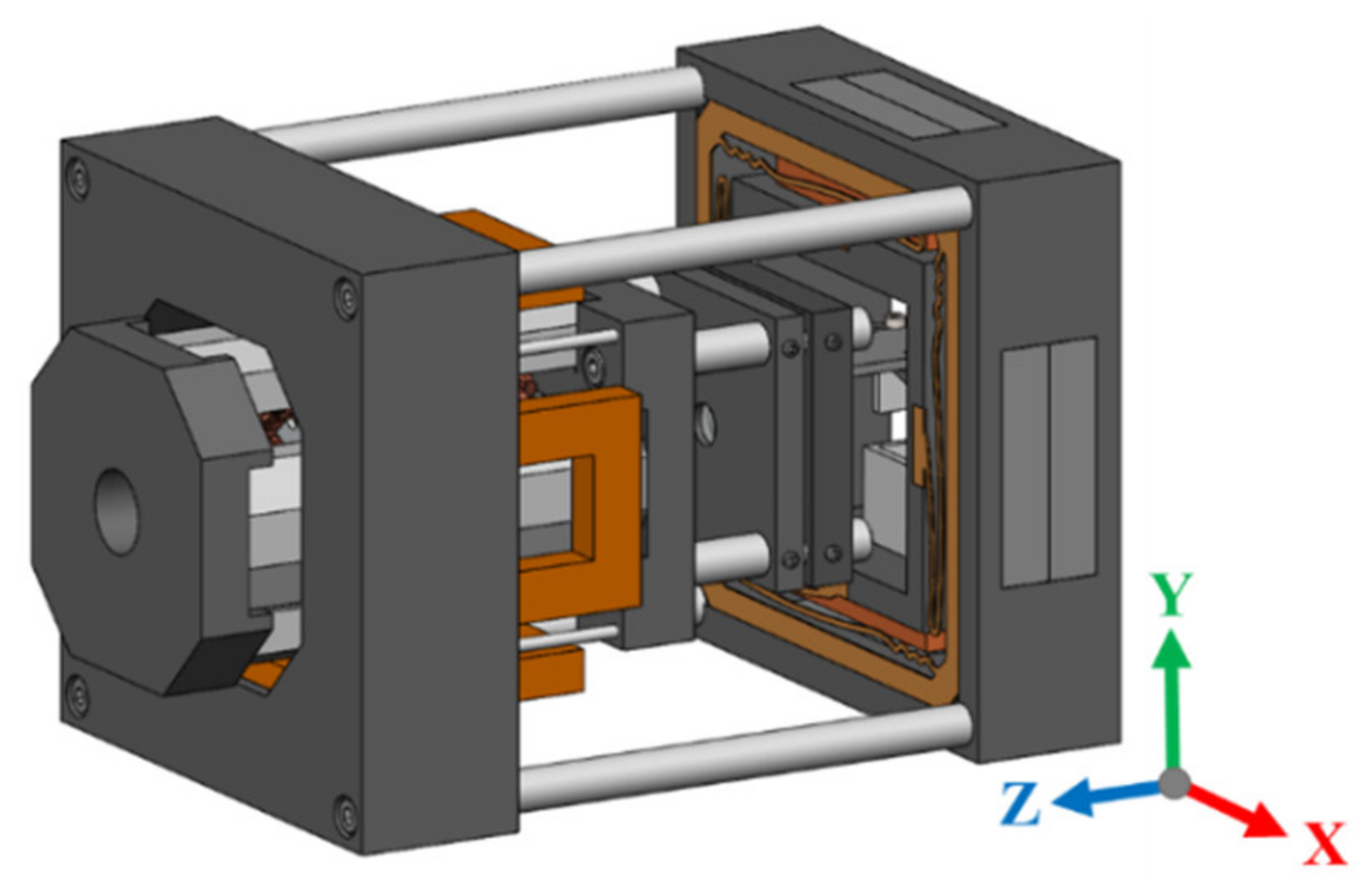
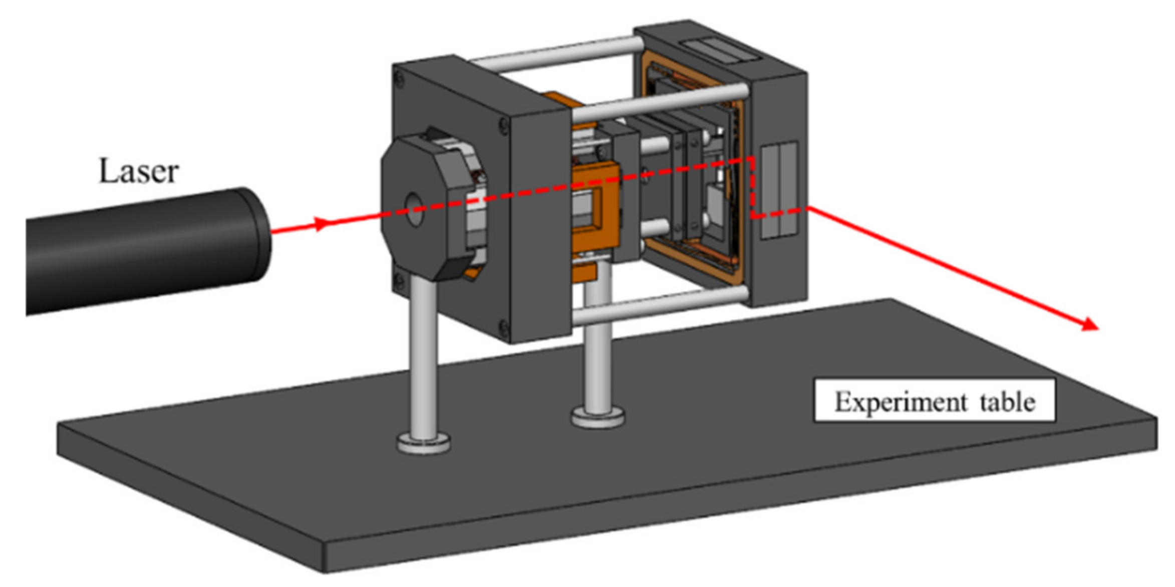
2.2. Structure
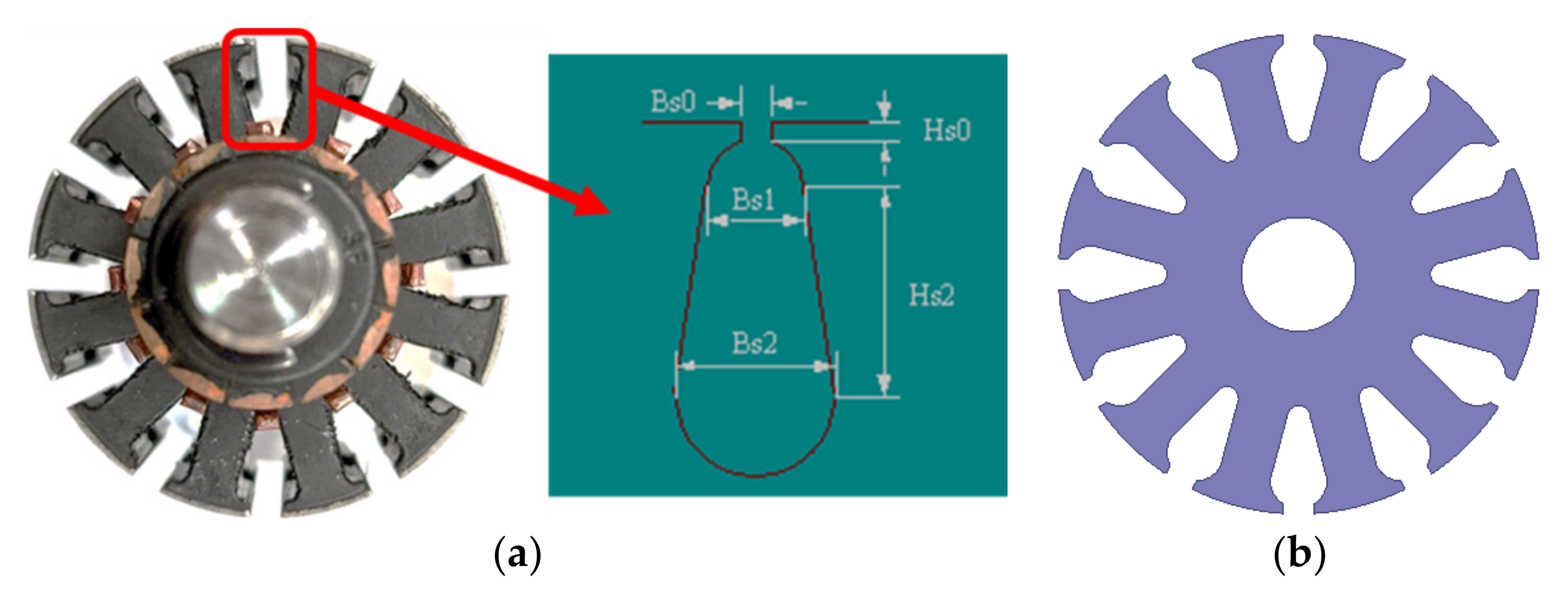
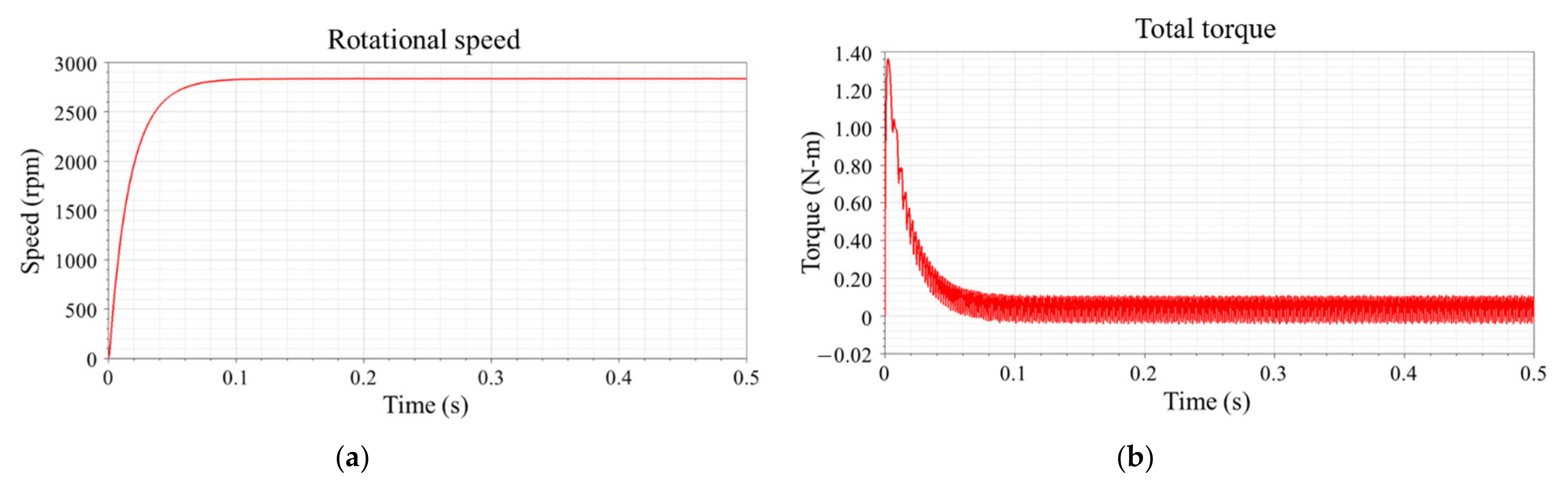
3. Design and Simulation of DC Brushed Motor
4. Design and Simulation of 4-DOF VCM
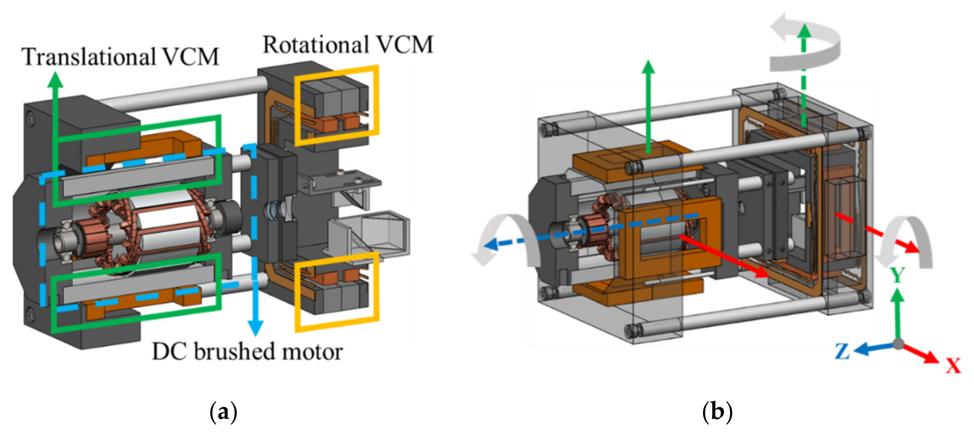
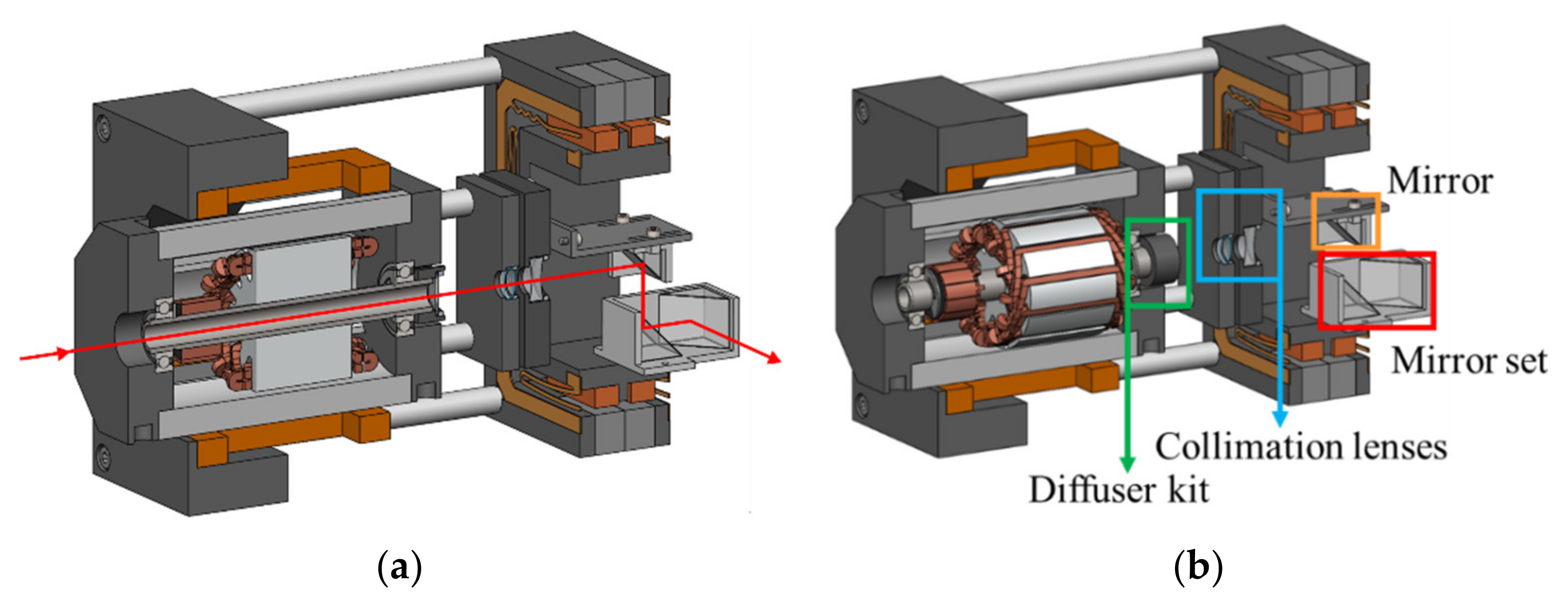
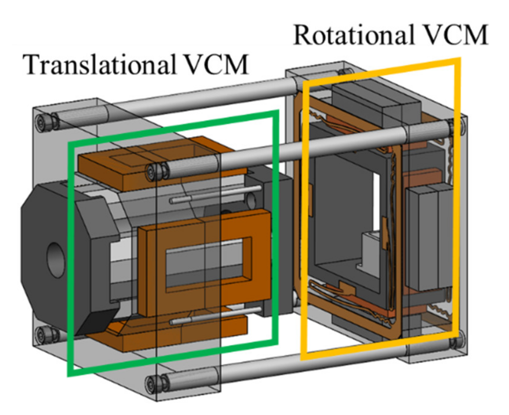
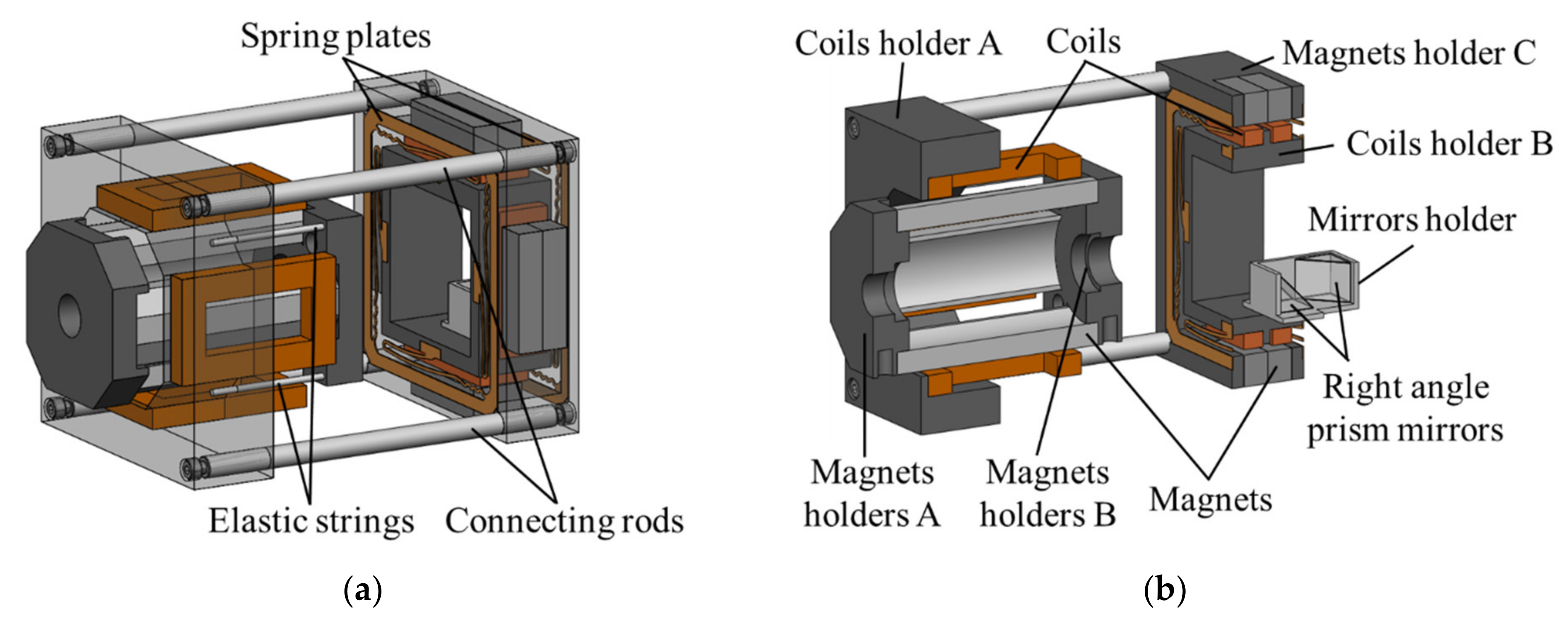
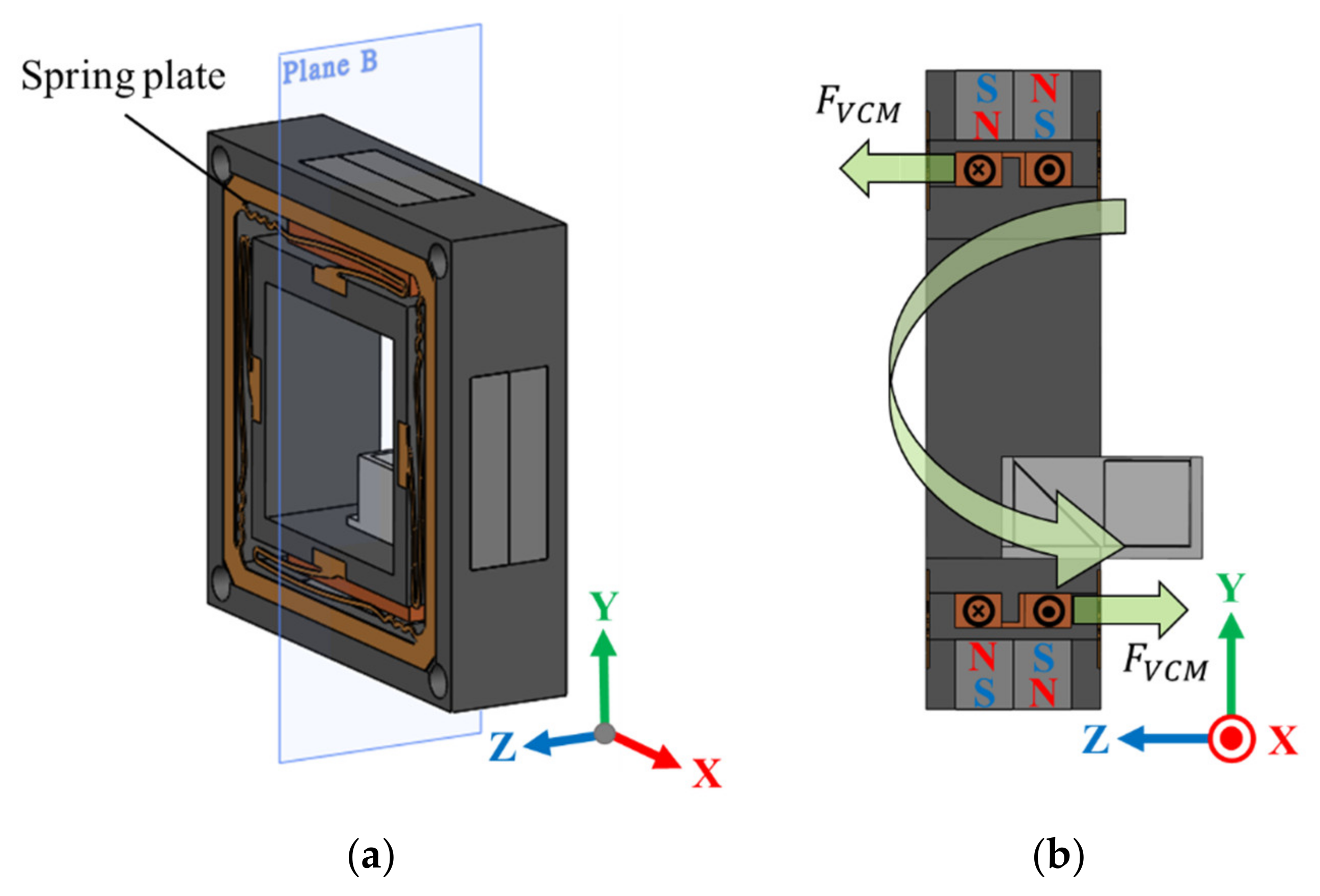
4.1. Structure and Working Principle of 4-DOF VCM
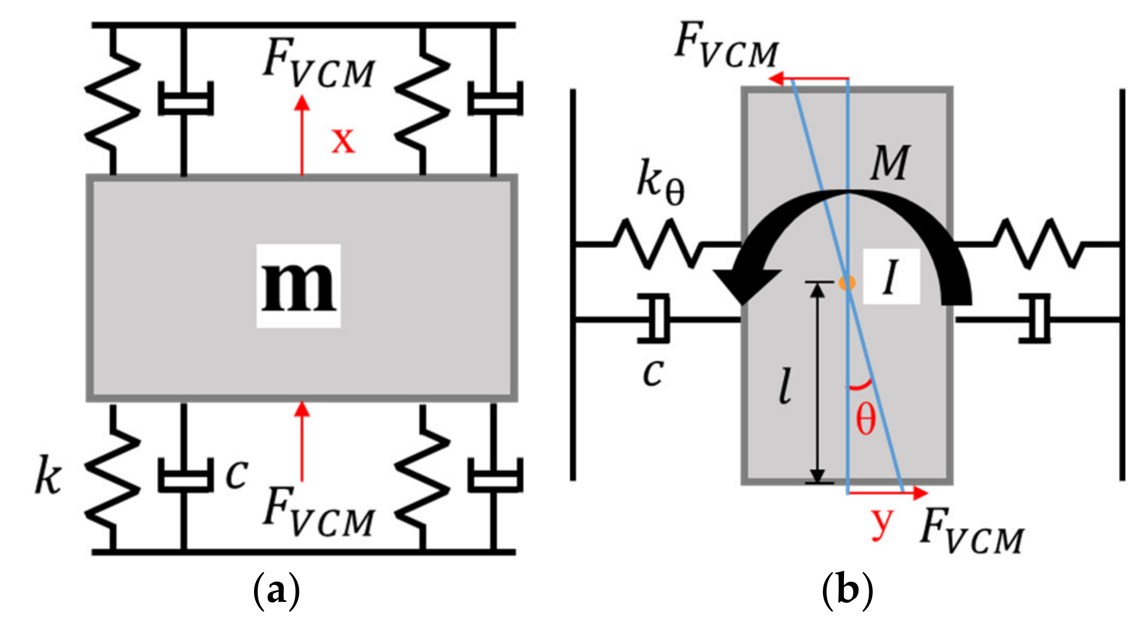
4.2. Mathematical Modeling
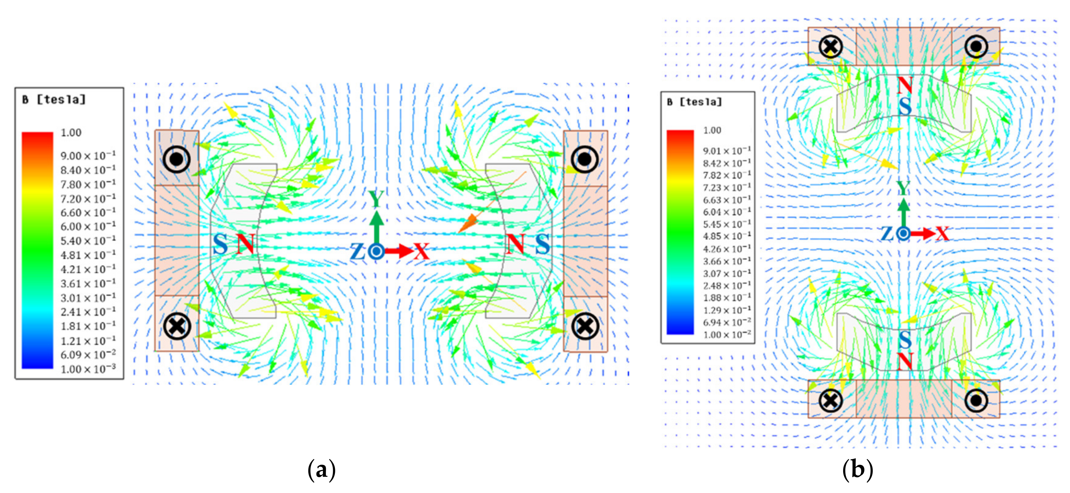
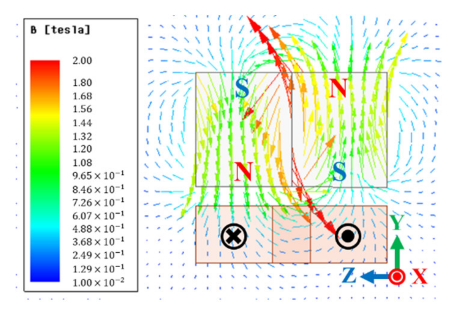
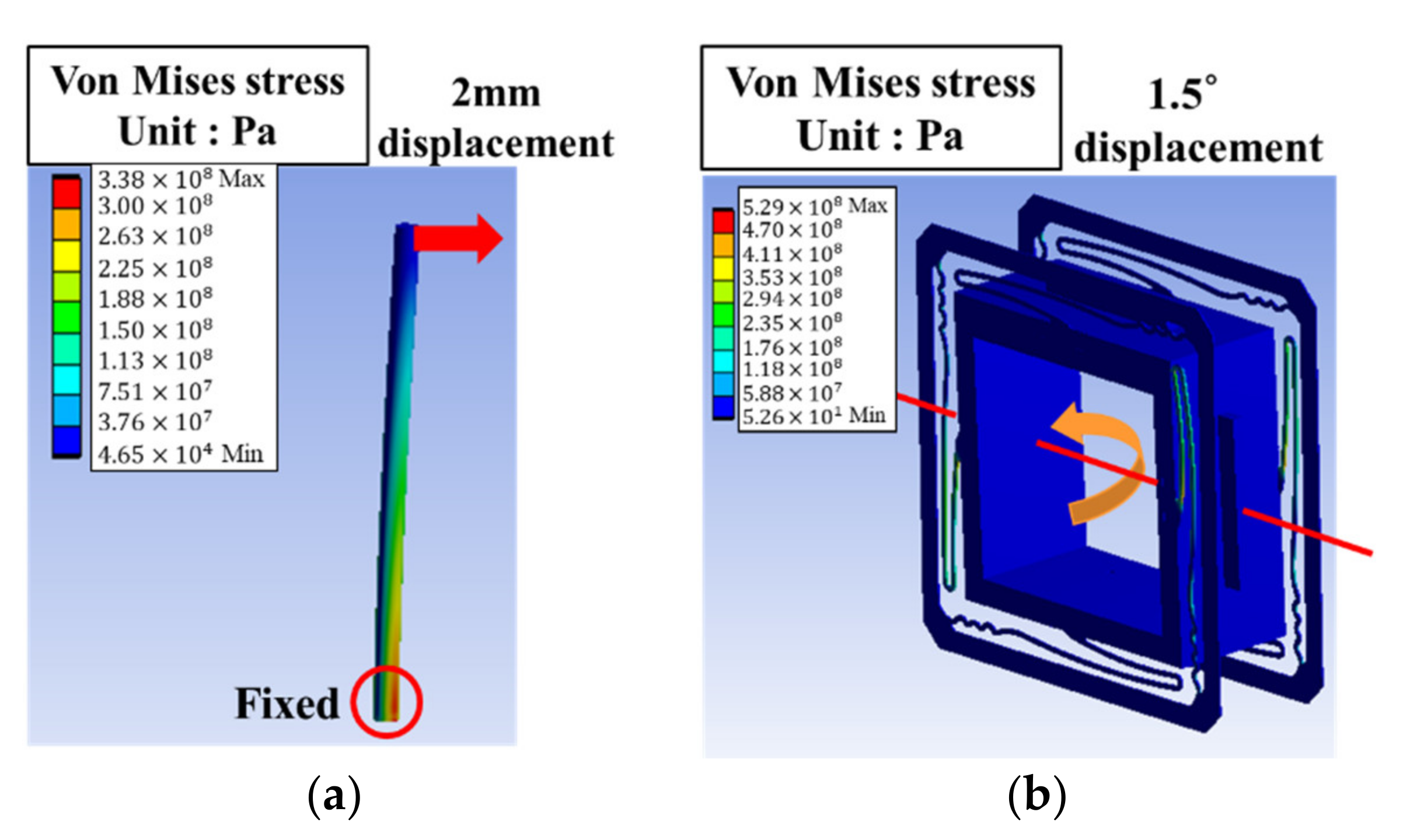
4.3. Simulation of Electromagnetic and Mechanical Structure
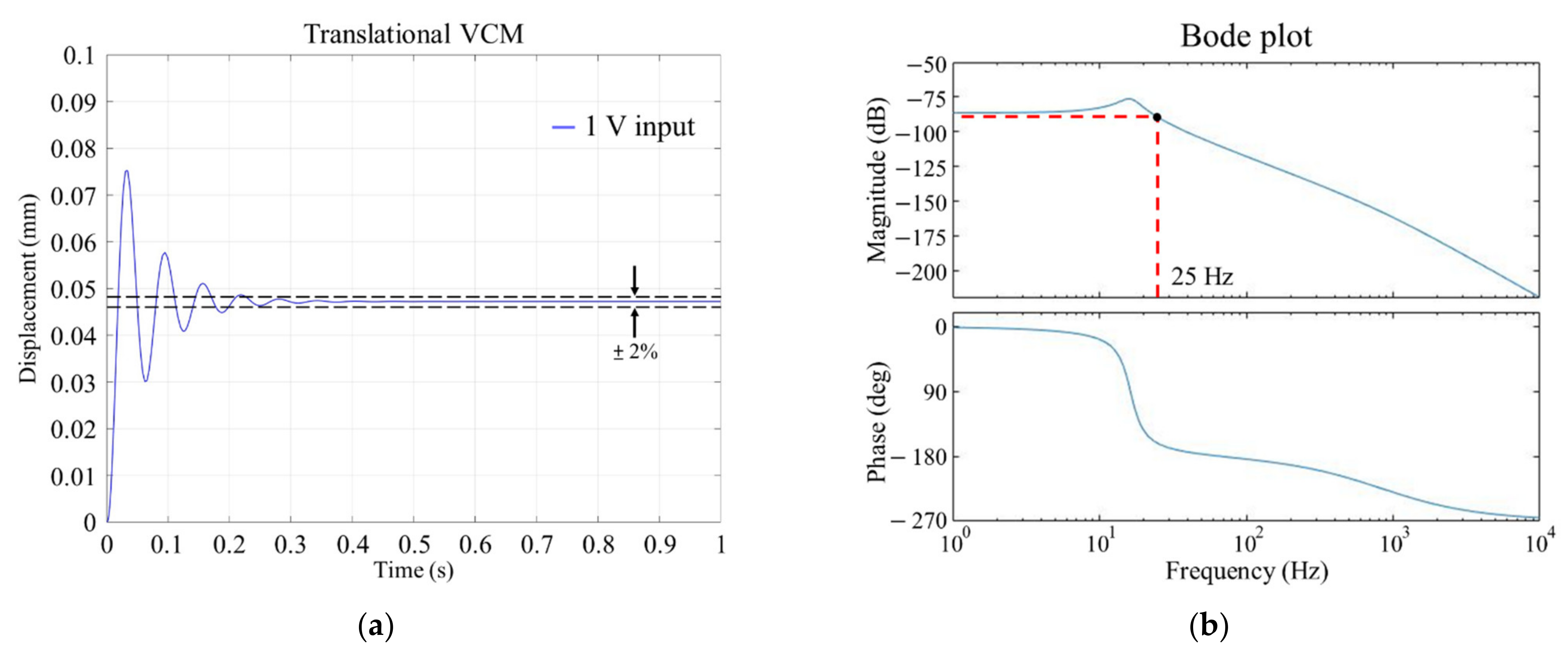
4.4. Dynamic Response Simulation
5. Conclusions
Author Contributions
Funding
Institutional Review Board Statement
Informed Consent Statement
Data Availability Statement
Acknowledgments
Conflicts of Interest
References
- Kuo, C.-C.; Chao, C.-S. Characterization of probe lasers for thin-film optical measurements. J. Russ. Laser Res. 2010, 31, 22–31. [Google Scholar] [CrossRef]
- Kim, D.I.; Rhee, H.-G.; Song, J.-B.; Lee, Y.-W. Laser output power stabilization for direct laser writing system by using an acousto-optic modulator. Rev. Sci. Instrum. 2007, 78, 103110. [Google Scholar] [CrossRef] [PubMed] [Green Version]
- Tricot, F.; Phung, D.H.; Lours, M.; Guérandel, S.; De Clercq, E. Power stabilization of a diode laser with an acousto-optic modulator. Rev. Sci. Instrum. 2018, 89, 113112. [Google Scholar] [CrossRef] [Green Version]
- Lamour, T.P.; Sun, J.; Reid, D.T. Wavelength stabilization of a synchronously pumped optical parametric oscillator: Optimizing proportional-integral control. Rev. Sci. Instrum. 2010, 81, 053101. [Google Scholar] [CrossRef]
- Sugiarto, I.T.; Watanabe, M.; Sunada, S.; Hyodo, M. Frequency stabilization of dual-mode microchip laser by means of beat frequency stabilization. Opt. Rev. 2019, 27, 98–107. [Google Scholar] [CrossRef]
- Lu, Y.; Fan, D.; Zhang, Z. Theoretical and experimental determination of bandwidth for a two-axis fast steering mirror. Optik 2013, 124, 2443–2449. [Google Scholar] [CrossRef]
- Shinshi, T.; Shimizu, D.; Kodeki, K.; Fukushima, K. A Fast Steering Mirror Using a Compact Magnetic Suspension and Voice Coil Motors for Observation Satellites. Electronics 2020, 9, 1997. [Google Scholar] [CrossRef]
- Wang, D.; Watkins, C.; Koppal, S.; Xie, H. A silicon optical bench with vertically-oriented micromirrors for active beam steering. Sens. Actuators A Phys. 2019, 298, 111586. [Google Scholar] [CrossRef]
- Long, Y.; Mo, J.; Wei, X.; Wang, C.; Wang, S. Design of a Moving-magnet Electromagnetic Actuator for Fast Steering Mirror through Finite Element Simulation Method. J. Magn. 2014, 19, 300–308. [Google Scholar] [CrossRef] [Green Version]
- Long, Y.; Wang, C.; Dai, X.; Wei, X.; Wang, S. Modeling and analysis of a novel two-axis rotary electromagnetic actuator for fast steering mirror. J. Magn. 2014, 19, 130–139. [Google Scholar] [CrossRef]
- Riza, M.; Hao, G. A flexure motion stage system for light beam control. Microsyst. Technol. 2018, 25, 3185–3191. [Google Scholar] [CrossRef]
- Hao, G.; He, X. Designing a monolithic tip-tilt-piston flexure manipulator. Arch. Civ. Mech. Eng. 2017, 17, 871–879. [Google Scholar] [CrossRef]
- Lin, R.; Li, Y.; Zhang, Y.; Wang, T.; Wang, Z.; Song, Z.; Dou, Z.; Qian, J. Design of A flexure-based mixed-kinematic XY high-precision positioning platform with large range. Mech. Mach. Theory 2019, 142, 103609. [Google Scholar] [CrossRef]
- Liu, H.; Fan, S.; Xie, X.; Zhang, Z.; Fan, D. Design and modeling of a novel monolithic parallel XY stage with centimeters travel range. Adv. Mech. Eng. 2017, 9. [Google Scholar] [CrossRef]
- Hsieh, C.-L.; Liu, C.-S.; Cheng, C.-C. Design of a 5 degree of freedom–voice coil motor actuator for smartphone camera modules. Sens. Actuators A Phys. 2020, 309, 112014. [Google Scholar] [CrossRef]
- Liu, C.-S.; Lin, P.-D.; Lin, P.-H.; Ke, S.-S.; Chang, Y.-H.; Horng, J.-B. Design and Characterization of Miniature Auto-Focusing Voice Coil Motor Actuator for Cell Phone Camera Applications. IEEE Trans. Magn. 2009, 45, 155–159. [Google Scholar] [CrossRef]
- Kim, H.Y.; Kim, H.; Gweon, D.G.; Jeong, J. Development of a novel spherical actuator with two degrees of freedom. IEEE/ASME Trans. Mechatron. 2015, 20, 532–540. [Google Scholar] [CrossRef]
- Lee, J.-S.; Kim, D.-K.; Baek, S.-W.; Rhyu, S.-H.; Kwon, B.-I. Newly Structured Double Excited Two-Degree-of-Freedom Motor for Security Camera. IEEE Trans. Magn. 2008, 44, 4041–4044. [Google Scholar] [CrossRef]
- Heya, A.; Hirata, K.; Niguchi, N. Dynamic Modeling and Control of Three-Degree-of-Freedom Electromagnetic Actuator for Image Stabilization. IEEE Trans. Magn. 2018, 54, 1–5. [Google Scholar] [CrossRef]
- Lin, Y.-H.; Liu, C.-S.; Yeh, C.-N. Design and Simulation of Novel 3-DOF Spherical Voice Coil Motor. Actuators 2021, 10, 155. [Google Scholar] [CrossRef]
- Specification of FSM-300-01 Fast Steering Mirror System. Available online: https://www.newport.com/p/FSM-300-01 (accessed on 11 November 2021).
- Chang, Y.-H.; Hao, G.; Liu, C.-S. Design and characterisation of a compact 4-degree-of-freedom fast steering mirror system based on double Porro prisms for laser beam stabilization. Sens. Actuators A Phys. 2021, 322, 112639. [Google Scholar] [CrossRef]
- Chang, Y.-H.; Liu, C.-S.; Cheng, C.-C. Design and Characterisation of a Fast Steering Mirror Compensation System Based on Double Porro Prisms by a Screw-Ray Tracing Method. Sensors 2018, 18, 4046. [Google Scholar] [CrossRef] [Green Version]
- Tran, T.-K.; Chen, X.; Svensen, O.; Akram, M.N. Speckle reduction in laser projection using a dynamic deformable mirror. Opt. Express 2014, 22, 11152–11166. [Google Scholar] [CrossRef] [PubMed] [Green Version]
- Ishikawa, H.; Shibase, A.; Weng, W.; Ono, M.; Furue, H. Reduction of laser speckle noise by using particle-dispersed liquid crystals. Mol. Cryst. Liq. Cryst. 2017, 646, 93–98. [Google Scholar] [CrossRef]
- Jian, Z.; Tong, Z.; Ma, Y.; Wang, M.; Jia, S.; Chen, X. Laser beam modulation with a fast focus tunable lens for speckle reduction in laser projection displays. Opt. Lasers Eng. 2019, 126, 105918. [Google Scholar] [CrossRef]
- Liu, C.S.; Lin, K.W.; Jiang, S.H. Development of precise autofocusing microscope based on reduction of geometrical fluctuations. In Proceedings of the SICE Annual Conference (SICE), Akita, Japan, 20–23 August 2012; pp. 967–972. [Google Scholar]
- Liu, C.-S.; Jiang, S.-H. A novel laser displacement sensor with improved robustness toward geometrical fluctuations of the laser beam. Meas. Sci. Technol. 2013, 24, 105101. [Google Scholar] [CrossRef]
- Liu, C.S.; Lin, K.W. Numerical and experimental characterization of reducing geometrical fluctuations of laser beam based on rotating optical diffuser. Opt. Eng. 2014, 53, 122408. [Google Scholar] [CrossRef]
- Pérez-Peña, A.; García-Granada, A.A.; Menacho, J.; Molins, J.J.; Reyes, G. A methodology for damping measurement of engineering materials: Application to a structure under bending and torsion loading. J. Vib. Control 2016, 22, 2471–2481. [Google Scholar] [CrossRef]


| Rotational Speed of DC Brushed Motor | Travel Range of Rotational VCM | Travel Range of Translational VCM | |
|---|---|---|---|
| Design goal | 2000 rpm | ±1.5° (±26.2 mrad) | ±0.05 mm |
| Parameter | Value |
|---|---|
| Outer diameter | 42 mm |
| Inner diameter | 10 mm |
| Stacking thickness | 30 mm |
| Stacking factor | 0.833 |
| Tooth width | 4.5 mm |
| Hs0 | 0.8 mm |
| Hs2 | 5.5 mm |
| Bs0 | 2.65 mm |
| Parameter | Value |
|---|---|
| Multiplex number | 1 |
| Coil pitch | 3 |
| Coil diameter | 0.404 mm |
| Coils per set | 30 turns |
| Coil Outer Dimensions | Coil Cross-Sectional Area | Magnet Dimensions | |
|---|---|---|---|
| Translational VCM | Length 84 mm, detailed in Figure 7a | ||
| Rotational VCM |
| Variable | Elastic String | Spring Plate |
|---|---|---|
| Material | Ti-6Al-4V | C17200 copper |
| Young’s modulus | 109 (GPa) | 128 (GPa) |
| Shear modulus | 43 (GPa) | 50 (GPa) |
| Yield strength | 860 (MPa) | 1143 (MPa) |
| Ultimate strength | 925 (MPa) | 1395 (MPa) |
| Dimensions | Φ 2.2 mm, Length 50 mm |
| Translational VCM | Rotational VCM | ||
|---|---|---|---|
| Parameter | Value | Parameter | Value |
| m (kg) | 1.875 | I (kg-m2) | 0.0002343 |
| k (N/m) | 19,724 | kθ (N-m/rad) | 35 |
| c (N-s/m) | 60 | c (N-s/m) | 20 |
| 2Kvcm (N/A) | 10.3 | Kvcm (N/A) | 4.36 |
| R (Ω) | 11.06 | R (Ω) | 4.66 |
| L (H) | 0.0164 | L (H) | 0.0024 |
| l (m) | 0.035 | ||
| Proposed Actuator | Developed Actuator [22] | |
|---|---|---|
| Degrees of freedom | 4 | 4 |
| Rotating movement (2000 rpm) | With | Without |
| Travel range for the translational movement | ±0.05 (mm) | ±0.04 (mm) |
| Travel range for the rotational movement | ±1.5° | ±0.3° |
| Bandwidth for the translational movement | 25 (Hz) | 39 (Hz) |
| Bandwidth for the rotational movement | 94 (Hz) | 10 (Hz) |
| Control system | Open loop control | Closed loop control |
Publisher’s Note: MDPI stays neutral with regard to jurisdictional claims in published maps and institutional affiliations. |
© 2021 by the authors. Licensee MDPI, Basel, Switzerland. This article is an open access article distributed under the terms and conditions of the Creative Commons Attribution (CC BY) license (https://creativecommons.org/licenses/by/4.0/).
Share and Cite
Liu, C.-S.; Wu, Y.-C.; Lan, Y.-J. Design of 4-DOF Voice Coil Motor with Function of Reducing Laser Geometrical Fluctuations. Actuators 2021, 10, 320. https://doi.org/10.3390/act10120320
Liu C-S, Wu Y-C, Lan Y-J. Design of 4-DOF Voice Coil Motor with Function of Reducing Laser Geometrical Fluctuations. Actuators. 2021; 10(12):320. https://doi.org/10.3390/act10120320
Chicago/Turabian StyleLiu, Chien-Sheng, Yu-Cheng Wu, and Yu-Jie Lan. 2021. "Design of 4-DOF Voice Coil Motor with Function of Reducing Laser Geometrical Fluctuations" Actuators 10, no. 12: 320. https://doi.org/10.3390/act10120320
APA StyleLiu, C.-S., Wu, Y.-C., & Lan, Y.-J. (2021). Design of 4-DOF Voice Coil Motor with Function of Reducing Laser Geometrical Fluctuations. Actuators, 10(12), 320. https://doi.org/10.3390/act10120320