


Abstract
This study combines theoretical analysis with experimental investigation to examine the hysteretic behavior and seismic mechanisms of self-centering timber frames incorporating reinforced concrete slabs through tests on two full-scale comparative specimens. One specimen was constructed with a floor slab, while the other was designed without a slab, and both were subjected to low-cycle reversed loading under identical test conditions. The seismic performance of the two specimens was comparatively evaluated in terms of hysteresis curves, load-carrying capacity, stiffness degradation, and energy dissipation capacity. The experimental results indicate that, under the adopted test configuration, the presence of the slab increases the initial stiffness of the frame by 81.25% and enhances its load-carrying capacity. In addition, prior to concrete cracking, the slab improves the energy dissipation efficiency through composite action. The slab also reduces the rate of post-tensioning loss by approximately 12.5%, indicating its beneficial role in mitigating such loss. Overall, this study provides both theoretical and experimental support for the quantitative evaluation of slab effects in self-centering timber frames.
1. Introduction
Timber structures, owing to their low carbon footprint, environmental sustainability, and lightweight yet high-strength characteristics, are increasingly regarded as an important option for sustainable construction [1,2]. However, conventional timber structures are prone to significant residual deformation and severe damage under major earthquakes, which results in high repair costs and limits their wider application [3]. To address this issue, the concept of resilient design has been introduced into timber structures, with the aim of mitigating post-earthquake damage and enabling the structure to be restored to functionality with little or no repair. Self-centering timber structures developed by the University of Canterbury have demonstrated minimal residual deformation and only slight damage after seismic events, and have therefore emerged as an important type of functional recovery structure.
Friction dampers, recognized for their readily adjustable energy dissipation capacity and cost-effectiveness, have been increasingly adopted in self-centering timber structures. Filiarault [4] pioneered their application in timber structures, thereby significantly reducing damage to the primary structure after earthquakes. Loo et al. [5] conducted numerical simulations and confirmed that friction dampers can effectively protect wall panels and frame joints from seismic damage [6]. By using friction dampers as connectors in rocking timber shear walls, a friction-dominated energy dissipation mechanism analogous to plastic hinge behavior was achieved, in which base shear is controlled through frictional dissipation [7]. Hashemi et al. [8] proposed a steel-timber hybrid rocking shear wall system integrating friction dampers with post-tensioned strands (PT strands), achieving low-damage self-centering performance while maintaining maximum inter-story drift ratios within code-specified limits. Subsequently, the seismic performance of self-centering friction connections, conventional friction connections, and traditional pinching connections in rocking timber walls was systematically evaluated. The results confirmed that self-centering friction dampers can effectively control residual displacement and reduce acceleration response [9]. Tatar and Dowden [10] proposed an uplift friction damper for self-centering CLT rocking walls. Through theoretical analysis and finite element simulations, they revealed that its stable energy dissipation and self-centering capacities are governed by key parameters such as wedge angle and friction coefficient. Li et al. [11] compared different friction materials and steel substrates, identifying the combination of non-asbestos organic (NAO) material and hot-rolled steel as providing the best damper performance. Subsequent studies further revealed that the slotted hole length and activation force level critically influence the hysteretic behavior of the system [12]. Ding et al. [13] developed a self-centering timber frame with NAO friction dampers (FD-SCG), achieving a residual drift of only 0.11% through performance-based design and substantially enhancing structural reparability. At the system level, Lepine-Lacroix and Yang [14] proposed a dual-articulated self-centering CLT shear wall system (DSCW) suitable for high-rise buildings and developed an equivalent energy design procedure, achieving excellent drift control and self-centering performance. Wang et al. [15] integrated a dual-tube self-centering buckling-restrained brace (DT-SCBRB) into a glulam frame. Nonlinear analysis demonstrated that this system can effectively control inter-story drift and limit residual deformation within a repairable range, and corresponding performance-level limits were proposed. Huang et al. [16] investigated the influence of bolt-hole edge collisions on the mechanical performance of self-centering timber structures, quantified the reinforcing effect of this behavior on self-centering timber joints, and developed a damage prediction model. More recently, Uarac et al. [17] validated the effectiveness of a system incorporating self-centering rocking walls and U-shaped steel plate energy dissipators through tests on a full-scale three-story timber structure. The system remained only minimally damaged even at an inter-story drift ratio of 4%, although the authors also noted that gravity systems can significantly affect its self-centering performance. Separately, Li et al. [18] experimentally investigated a post-tensioned steel-timber hybrid frame equipped with tension-only braces. They found that these braces considerably enhance the initial stiffness of the frame but contribute only limited energy dissipation. The tests also confirmed that screw connections can delay joint opening and increase residual deformation. Collectively, these studies have advanced the development and refinement of friction-based energy dissipation and self-centering technologies in timber structures. Chen et al. [19] summarized the recent experimental, analytical, and numerical progress in self-centering mass timber structures, highlighting their potential in resilient timber construction. Froozanfar et al. [20] reviewed self-centering rocking systems for earthquake-resistant building structures and noted that further analytical and experimental validation is still needed for practical implementation. Uarac et al. [17] experimentally validated the feasibility of a full-scale three-story mass timber structure equipped with post-tensioned self-centering rocking walls. In the field of timber-concrete composite systems, Shi et al. [21] pointed out that composite action and connection behavior are key factors governing stiffness, force transfer, and overall structural performance. Nerilli et al. [22] investigated the bond–slip behavior of GFRP rebars embedded in concrete under alkaline and thermal conditioning and showed that environmental degradation can significantly affect interfacial performance and damage evolution, highlighting the importance of considering material degradation and interface behavior in composite structural systems. However, the stage-wise influence of reinforced concrete slab participation on the hysteretic response of post-tensioned self-centering timber frames has not yet been clearly quantified.
Although existing design standards such as Eurocode 5 provide useful guidance for the design of timber members and composite action, limited attention has been given to the stage-dependent slab participation in post-tensioned self-centering timber frames under cyclic loading. In particular, current provisions do not explicitly quantify the effect of slab participation on stiffness transition, hysteretic response, or energy dissipation in such systems. This limitation highlights the need for further experimental and analytical research to support future refinement of design and assessment approaches.
In timber frame structures, floor slabs play a crucial role by providing diaphragm action, which significantly enhances structural integrity and contributes substantially to the overall stiffness of the structure. However, existing studies on self-centering systems have been predominantly based on analyses of slab-free beam-column joints, largely neglecting the influence of floor slabs in post-tensioned self-centering timber frames. Furthermore, current research generally assumes that the seismic performance of such frames is governed primarily by the beam-column members, PT strands, and friction dampers, while overlooking the contribution of the floor slab to both energy dissipation and flexural resistance. This knowledge gap consequently limits the current design, seismic performance analysis, and evaluation of such structures. In particular, the stage-wise recentering and energy dissipation mechanisms of self-centering frame structures incorporating floor slabs remain insufficiently understood.
To address the aforementioned research gaps, this study presents an integrated experimental and theoretical investigation of a full-scale post-tensioned self-centering timber frame incorporating a reinforced concrete slab. Rather than merely confirming the existence of slab effects in self-centering timber frames, the present study further clarifies the stage-wise influence of reinforced concrete slab participation on the hysteretic response, stiffness evolution, load-carrying capacity, and energy dissipation behavior of post-tensioned self-centering timber frames. A quasi-static cyclic loading test was conducted on this specimen, and its performance was systematically compared with that of a counterpart without a slab. Based on the experimental results, the load-carrying capacity and hysteretic behavior under different conditions were analyzed using skeleton curves. A detailed investigation was also carried out into the stiffness evolution reflected in the hysteretic loops for each case, together with the underlying mechanisms responsible for these changes. Furthermore, the energy dissipation capacity of the structure was evaluated by examining variations in the equivalent viscous damping ratio. Through the combined use of theoretical analysis and experimental investigation, this study provides a comprehensive understanding of the working mechanism and seismic performance of post-tensioned self-centering timber frames with reinforced concrete slabs.
2. Configuration of Self-Centering Timber Frames with Reinforced Concrete Floor Slabs
As summarized in Table 1, existing studies on self-centering timber structures have mainly focused on slab-free systems, including self-centering timber frames, rocking walls, and related hybrid systems, while the influence of floor slab participation has rarely been considered explicitly. However, in practical timber frame structures, floor slabs are indispensable structural components and can make unavoidable contributions to the seismic performance of the system, particularly in terms of stiffness, force transfer, and hysteretic response. Therefore, it is necessary to further investigate the role of slab participation in post-tensioned self-centering timber frames. On this basis, the configuration of the self-centering timber frame with a reinforced concrete floor slab considered in this study is introduced as follows.
Table 1.
Comparison between the present study and representative studies in the literature.
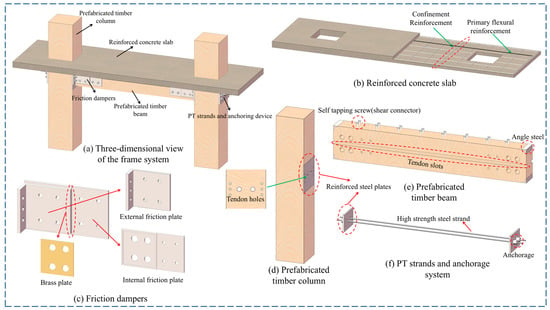
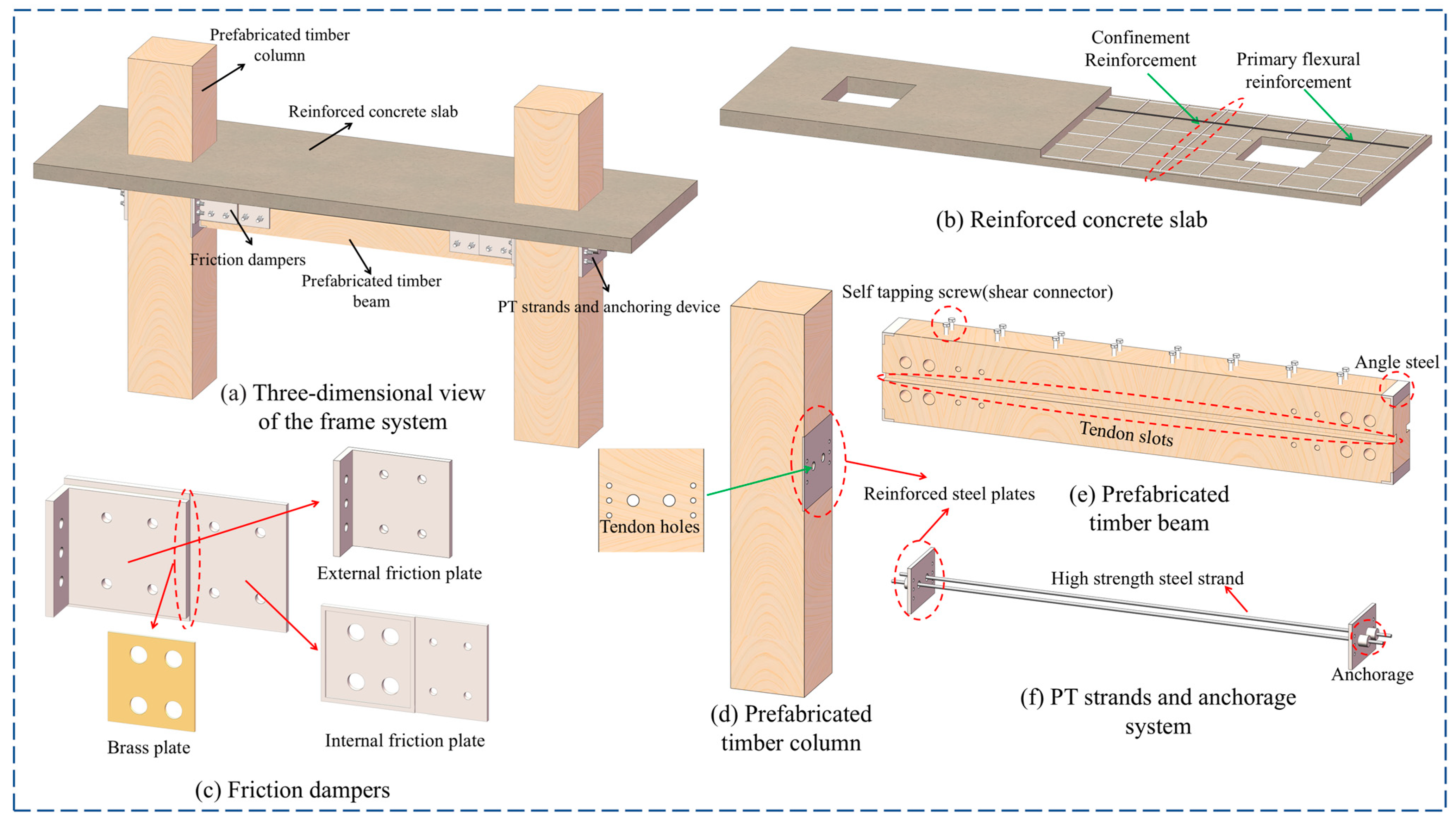
By taking advantage of the performance benefits of both friction dampers and reinforced concrete slabs, a post-tensioned self-centering timber frame incorporating friction dampers and a reinforced concrete slab was developed, as illustrated in Figure 1. The structure mainly consists of five key components: timber beams, timber columns, a reinforced concrete slab, friction dampers, and PT strands with their anchorage systems. Slots are machined on both sides of the timber beam, while circular holes are pre-drilled at the corresponding locations in the column to allow the PT strands to pass through. To mitigate local damage caused by perpendicular-to-grain compression at the beam-column interface, reinforced steel plates are installed on the column side at the contact zone. These steel plates are bolted to the column. Angle steel connectors are fastened to the beam ends using screws to prevent local crushing during joint rotation. In addition, thick steel plates are installed at both the tensioning and anchorage ends of the PT strands on the beam and column sides for protection. Self-tapping screws are installed on top of the timber beams to act as shear connectors between the timber beams and the reinforced concrete slab.
Figure 1.
Configuration of the post-tensioned self-centering timber frame with a reinforced concrete slab.
The friction damper consists of three main components: an L-shaped external friction plate, an internal friction plate, and a brass plate. To create a stable brass-on-steel friction interface, a groove is machined on the outer side of the internal friction plate to accommodate the brass friction plate. The damper is assembled by clamping the L-shaped external friction plate, the internal friction plate, and the brass plate together using four sets of high-strength friction bolts.
The L-shaped external friction plate is connected to the timber column by three sets of high-strength friction bolts, allowing the two components to act as an integral unit during joint deformation. Similarly, the internal steel friction plate is connected to the timber beam by four sets of connecting bolts, ensuring coordinated deformation of the two components. The bolt holes in the L-shaped external friction plate are the same diameter as the friction bolts, whereas the holes in the timber beam, internal friction plate, and brass plate are intentionally oversized. This arrangement allows relative sliding between the internal and external friction plates, thereby generating frictional resistance.
3. Hysteretic Model for Self-Centering Timber Joints with Floor Slabs
Because the joint rotation process involves three key response points—decompression, joint opening, and slab cracking—the theoretical hysteresis model of the self-centering timber frame with a slab can be divided into three distinct phases: the elastic phase (pre-opening phase), the frictional energy dissipation phase, and the plastic deformation phase. The transition between these phases is governed by changes in joint stiffness, with each key point corresponding to a distinct stiffness transition.
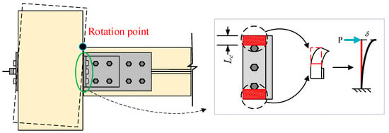
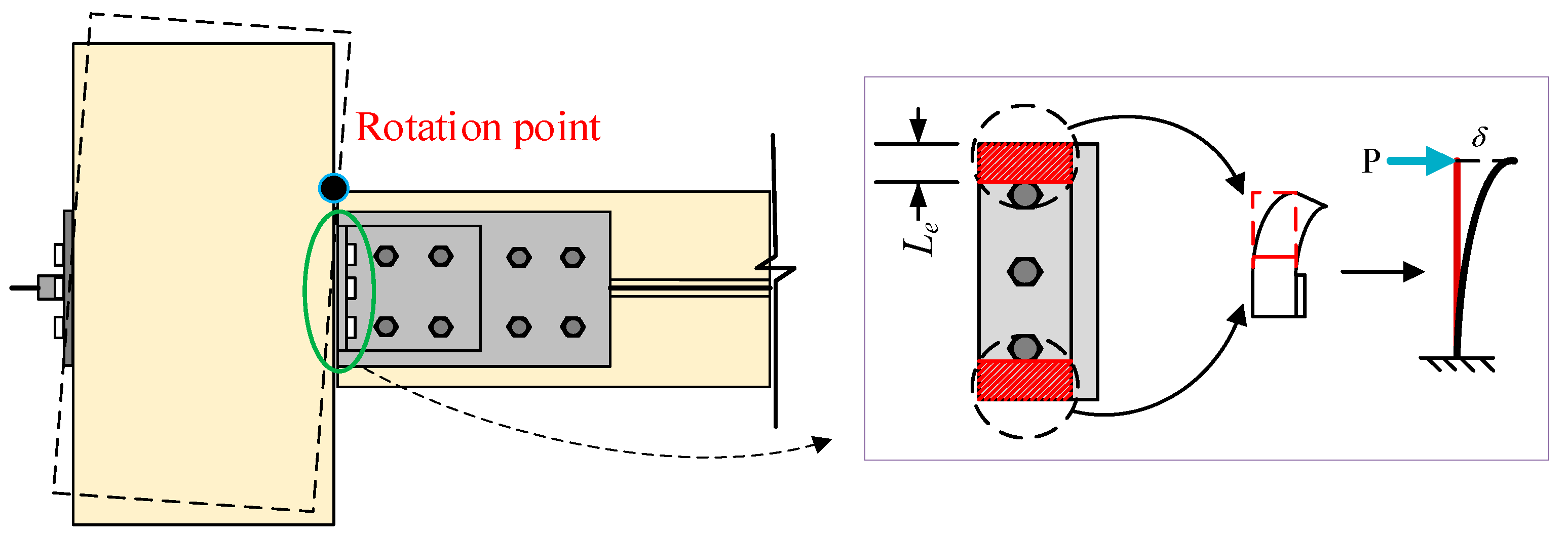
Phase I: Elastic phase. In this phase, the joint remains closed, and the frame and slab act compositely. The structural stiffness is provided by the effective flange width of the slab, the stiffness of the beam-column joint, the connecting steel plates, and the post-tensioning force. The lateral stiffness of the beam-column joint in this stage can be calculated using the simplified method illustrated in Figure 2.
Figure 2.
Simplified model for stiffness calculation of the beam-column joint.
Based on the simplified configuration described above, the lateral stiffness of the structure can be expressed as follows:
where kconnect is the connection stiffness provided by the L-shaped external friction plates; (EI)c denotes the flexural stiffness of the column; (EI)b represents the flexural stiffness of the timber-concrete composite beam, H is the vertical distance from the column-base hinge to the beam-column joint (or the center of rotation, COR); and L is the horizontal distance from the beam-column joint to the beam-end restraint.
As shown in Figure 2, the beam-column joints in this frame are connected by L-shaped external friction plates. The connection stiffness provided by these plates is primarily derived from their resistance to the prying force P, which develops at the plate ends when relative rotation occurs at the joint.
As shown in Figure 2, the end of the external friction plate (hereinafter referred to as the end plate) can be idealized as a cantilever beam, with the anchor bolt at its end acting as a fixed support. When subjected to the prying force P, the cantilever undergoes a deflection δ, and the corresponding connection stiffness, kconnect, can be expressed as:
where Le is the distance from the end of the end plate to the outermost connecting bolt, Ie represents the moment of inertia of the end plate, E denotes the elastic modulus of the end plate material, be is the plate width, and t is the thickness of the end plate.
According to the study by Shi et al. [23], the flexural rigidity of a timber–concrete composite beam considering the effect of prestressing can be calculated as follows:
where EcIc, EwIw, and EpIp represent the flexural rigidity of the concrete component, the timber beam, and the PT strands in the composite beam, respectively.
To account for the composite action between the concrete and the steel reinforcement, the term EcIc is modified in accordance with the GB 50010 (Code for Design of Concrete Structures) [24]. The modified stiffness is given by: , where α is an empirical coefficient, typically ranging from 3.0 to 5.0, and ρ denotes the reinforcement ratio.
The flexural stiffness of the column, (EI)c, was calculated based on the principles of mechanics of materials using the material properties and geometric dimensions obtained from the tests.
Based on this stiffness, the joint moment in the elastic stage can be expressed as: , where θ1 is the maximum rotation angle before joint opening.
Based on the preceding derivation, the horizontal displacement at the column end, Δ1, at the critical point of joint opening can be expressed as:
Phase II: Frictional energy dissipation phase. In this phase, the friction dampers are activated as the beam-column interface begins to open. Compared with Phase I, the structural stiffness undergoes a slight reduction. Because the slab and the timber beam act compositely as a T-shaped member, with the slab serving as the flange, the stiffness in this phase is primarily provided by the PT strands and the T-beam. Both the concrete and the reinforcing steel in the slab contribute to the overall flexural capacity of the frame. Accordingly, the joint moment capacity at this stage, denoted as M2, can be expressed as follows.
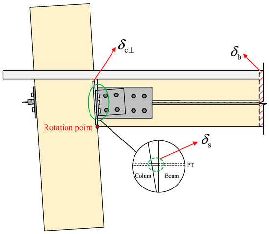
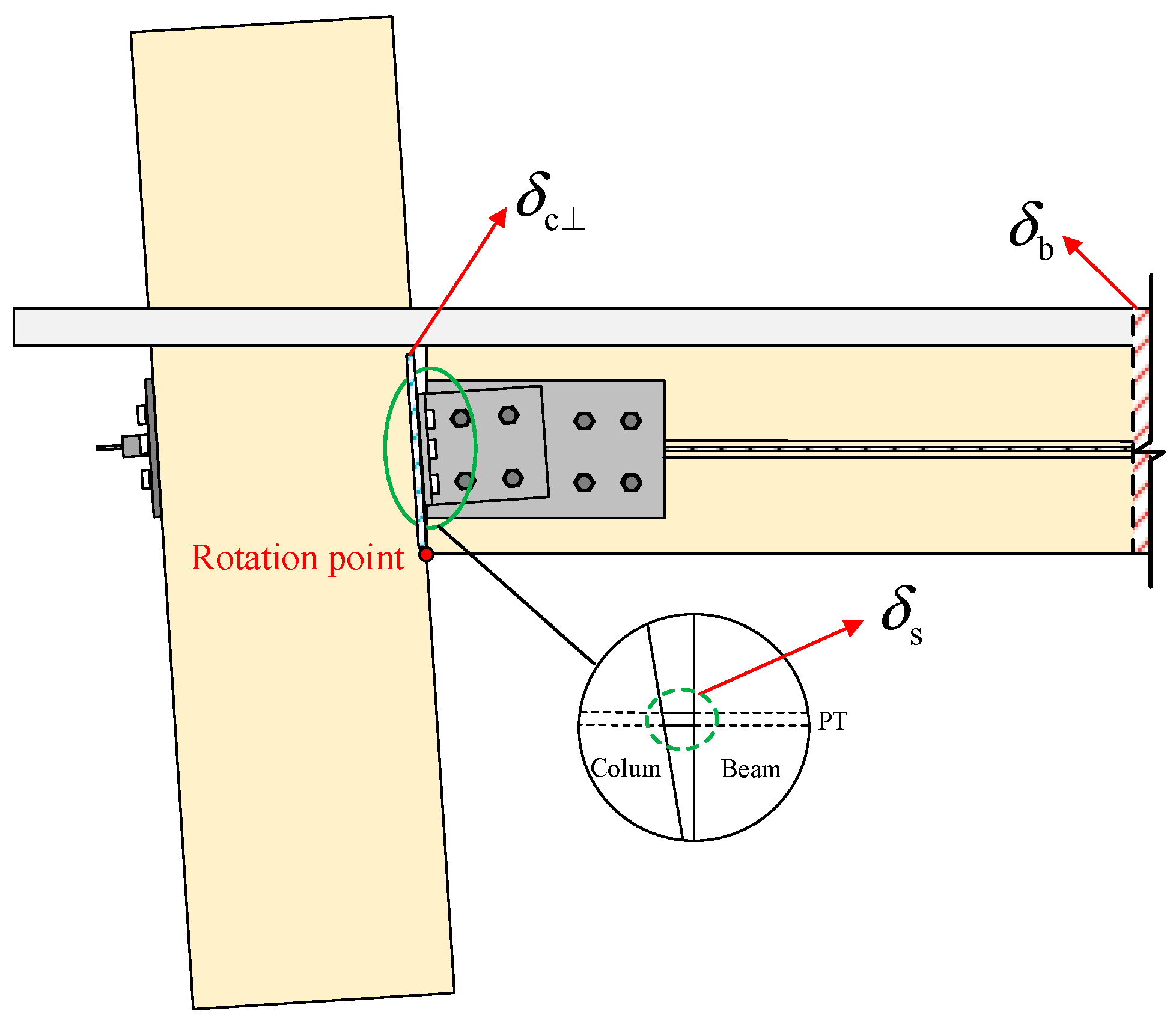
When the joint rotates through a rotation angle θr, the theoretical elongation of the PT strands, denoted by δs, can be expressed as . However, the actual elongation of the strands is reduced by the axial compressive deformation of the timber beam, δb, caused by the squeezing effect of the post-tensioning force, as well as by the deformation of the timber column under transverse compression, . The total compressive deformation of the beam-column system is defined as δtotal, and the axial stiffness of the timber column under transverse compression is defined as . Therefore, the actual elongation of the tendon can be expressed as: . By defining the axial force in the timber beam as Nb, and noting that the axial force in the beam is equal to that in the column, the following relationships can be obtained: , , and thus, .
At this stage, the increment in the post-tensioning force is nearly equal to the axial force increment in the T-shaped beam considering the effective flange width, as illustrated in Figure 3, i.e., . Consequently, the total axial compressive stiffness of the beam-column system, denoted as ktotal, is the series combination of the corresponding component stiffnesses: .
Figure 3.
Schematic of PT Strands Elongation and Composite Beam Shortening Relationship.
At this stage, the increment in the post-tensioning force after joint opening is nearly equal to the increment in the axial force of the beam-column system, while accounting for the effective flange width of the slab and the transverse compressive damage to the column. This relationship is illustrated in Figure 3, i.e., .
Where ksi is the axial stiffness of the i-th PT strand, δsi denotes the elongation of the i-th PT strand, kb represents the effective axial stiffness (parallel-to-grain) of the composite timber beam considering the slab flange, and δb is the axial shortening (compressive deformation) of the beam.
The total axial shortening of the timber beam δtotal is given by:
The post-tensioning force is given by:
The moment at the beam end contributed by the post-tensioning force is given by:
When the beam-column joint rotates about the top of the beam end, the slab is primarily subjected to tension. Since the tensile contribution of concrete can be neglected, the moment contribution of the slab, denoted as Mslab, is assumed to be provided mainly by the longitudinal reinforcement and can be expressed as follows:
Therefore, the joint moment at this stage, denoted as M2, can be expressed as:
When the beam-column joint rotates about the bottom of the beam end, the slab is primarily subjected to compression. Given the significant contribution of concrete under compression, the flexural capacity of the slab is provided by both the longitudinal reinforcement and the compressive concrete. Accordingly, the expressions for the slab moment contribution, Mslab, and the joint moment, M2, can be written as follows:
Thus, the lateral force can be expressed as: .
Let Δ2 denote the horizontal displacement at the column end at this stage, LF the distance from the loading point to the center of rotation at the column base, and Hs the distance from the PT strands to the top of the beam. Neglecting fabrication and assembly tolerances, it may be assumed that The relationship between Δ2 and LF can be expressed as: , .
Thus, the stiffness in Phase II can be derived as:
Phase III: Slab Cracking Phase. Compared with Phase II, the structural stiffness exhibits a moderate reduction in this phase, the extent of which depends on the degree of slab cracking. According to the Chinese design code GB 50010 (Code for Design of Concrete Structures) [23], for elastoplastic analysis considering slab cracking effects, the effective flange width should be reduced to 50% of its initial value. This reduction implies a diminished contribution of the slab concrete to the overall flexural resistance.
When the beam-column joint rotates about the bottom of the beam end, the slab is predominantly subjected to compression, and the contribution of concrete becomes significant. The flexural capacity at the beam end under this condition can be expressed as follows:
When the beam-column joint rotates about the top of the beam end, the slab is predominantly subjected to tension, and the contribution of concrete to the load-bearing capacity can be neglected. The flexural capacity at the beam end under this condition can be expressed as follows:
Thus, the lateral force can be expressed as: . Owing to slab cracking, the longitudinal reinforcement in the slab is assumed to have yielded. The corresponding yield strain is determined by the material properties of the steel as: , Let hs denote the effective depth of the longitudinal reinforcement. By considering deformation compatibility, the following geometric relationship can be obtained: , . Accordingly, the stiffness in Phase III can be expressed as:
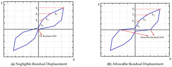
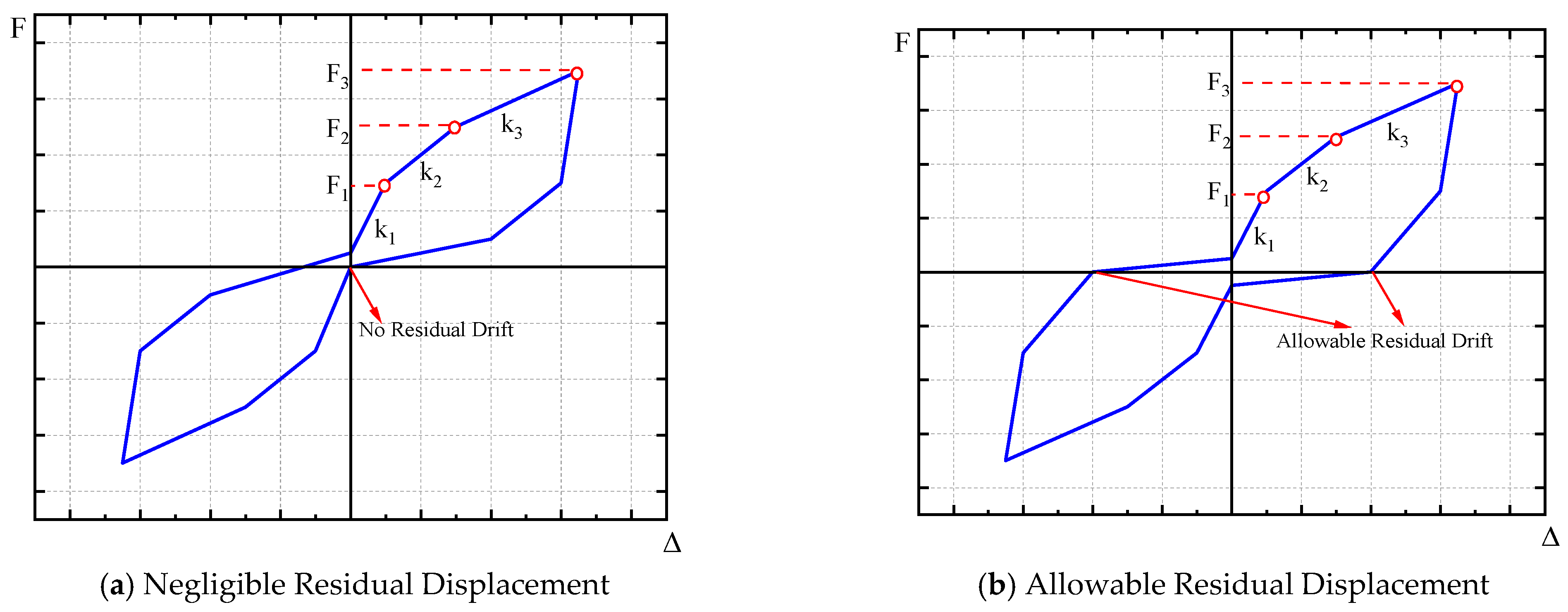
Based on the preceding derivation, the theoretical hysteresis curves of the post-tensioned self-centering timber frame with a slab are illustrated in Figure 4. In the following experimental section, Equations (1)–(5), (6)–(14) and (15)–(17) are used to interpret the response transitions in Phases I, II, and III, respectively. In self-centering structures, systems can generally be classified as fully self-centering or semi-self-centering according to the degree of recentering, which is governed by the balance between the applied post-tensioning force and the energy dissipation capacity of the structure. Accordingly, the post-tensioned self-centering timber frame with a slab investigated in this study can also be classified into two types: a fully self-centering system with negligible residual displacement, as shown in Figure 4a, and a semi-self-centering system with allowable residual displacement, as shown in Figure 4b.
Figure 4.
Idealized hysteresis curves.
4. Cyclic Loading Tests on Self-Centering Timber Frames with Concrete Slabs
4.1. Test Specimen
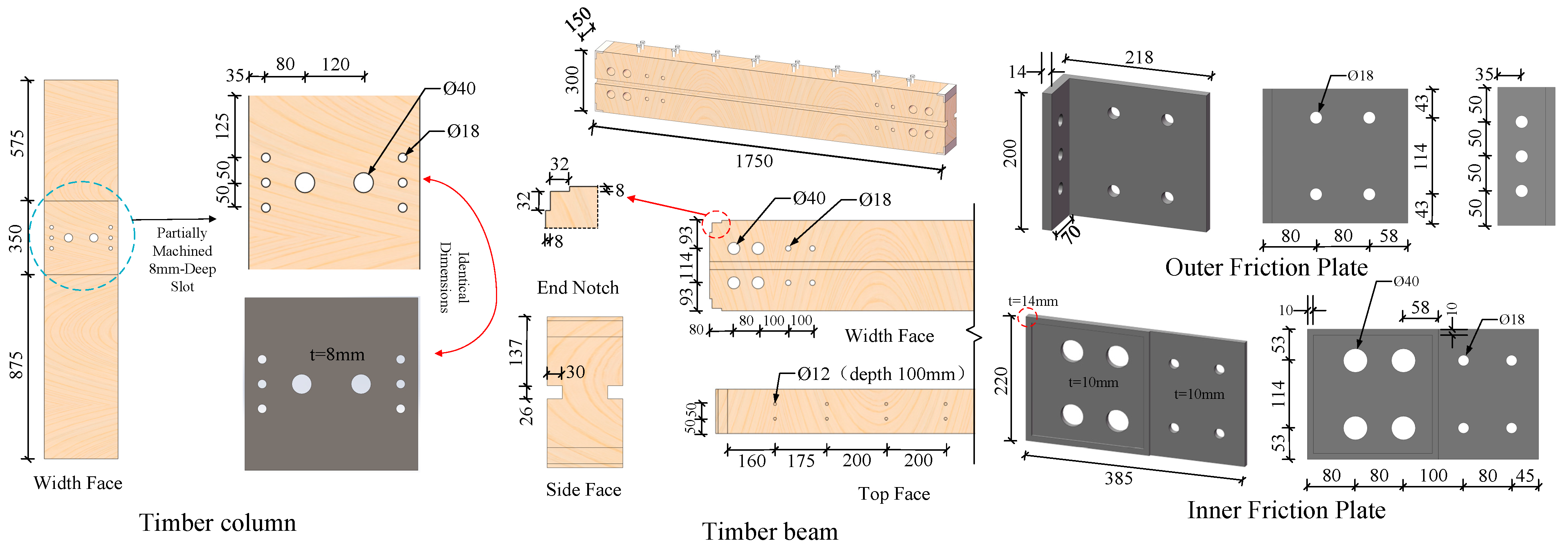
The detailed design of the test specimen is shown in Figure 5. Both the timber columns and beams were fabricated from Douglas fir solid timber. According to material tests conducted in accordance with GB/T 50329—2012 (Standard for Test Methods of Timber Structures) [25] and GB/T 26899—2011 (Glued Laminated Timber for Structural Purposes) [26], the material exhibited the following mechanical properties: an elastic modulus parallel to the grain of 12.5 GPa; elastic moduli perpendicular to the grain of 1516 MPa in the radial direction and 827 MPa in the tangential direction; a compressive strength parallel to the grain ranging from 50 to 70 MPa; and a compressive strength perpendicular to the grain ranging from 5 to 10 MPa.
Figure 5.
Dimension details of components.
The column had a length of 1800 mm and a cross-sectional dimension of 350 mm × 350 mm. The beam had a length of 1750 mm and a cross-sectional dimension of 300 mm × 150 mm. The reinforced concrete (RC) slab measured 3250 mm in length, 950 mm in width, and 80 mm in thickness. It was reinforced in both the longitudinal and transverse directions with HPB300 steel bars, which had a yield strength of 270 MPa and an elastic modulus of 200 GPa. The reinforcement layout was Ø8@180 mm in the longitudinal direction and Ø8@200 mm in the transverse direction. The concrete was designated as Grade C30, with a characteristic cube compressive strength of 30 MPa and an elastic modulus of 30 GPa.
The friction dampers consisted of an external L-shaped steel plate with a flange measuring 218 mm in length, 200 mm in height, and 14 mm in thickness, connected to a 70 mm-wide web. The internal component was a flat steel plate measuring 385 mm in length, 220 mm in height, and 10 mm in thickness. A 4 mm-deep groove was machined on the outer side of this internal plate to accommodate and secure a brass friction plate measuring 198 mm in length, 200 mm in height, and 6 mm in thickness. The positions and dimensions of the holes for the friction bolts and connection bolts are shown in Figure 5.
The self-tapping screws used to connect the slab to the timber beam were Grade 8.8 galvanized M16 screws, with a yield strength of 640 MPa and an elastic modulus of 200 GPa. The PT strands had a nominal diameter of 15.2 mm and an ultimate tensile strength of 1860 MPa. All steel plates used in the specimen were fabricated from Grade Q235 steel, with a yield strength of 235 MPa and an elastic modulus of 210 GPa. The coefficient of friction between the brass shim and the steel plate, determined from prior tests conducted by the research group, was 0.3 [27].
4.2. Test Setup and Instrumentation Layout
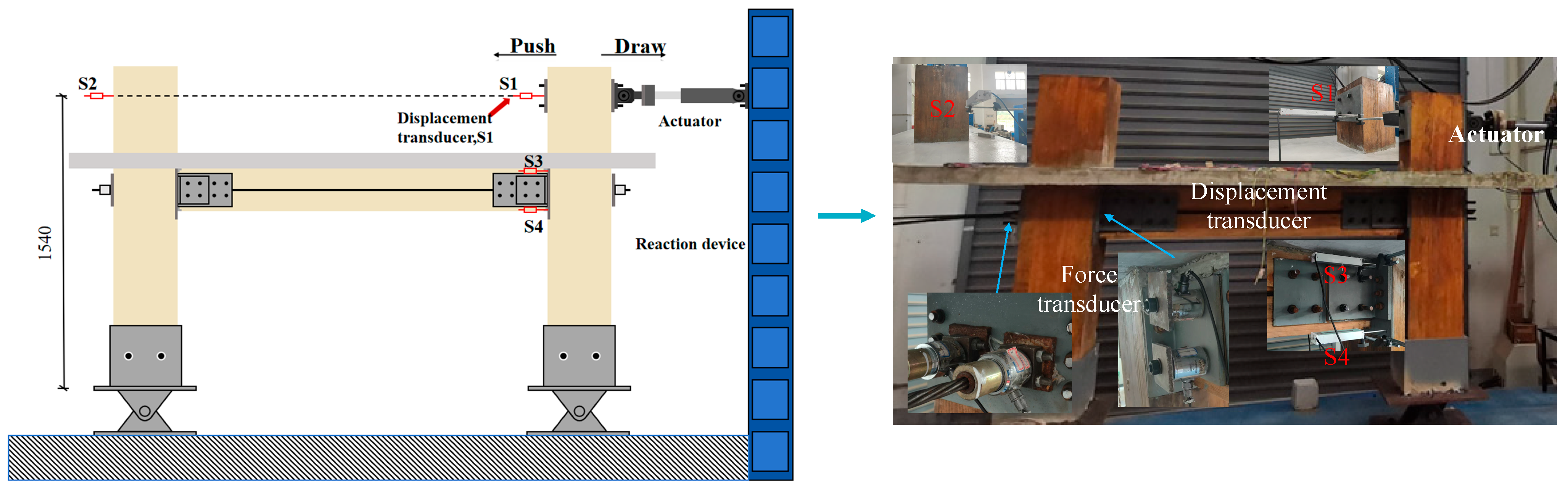
The test setup is illustrated in Figure 6. The global frame was connected to the base of the loading apparatus through pinned connections. The spacing between the two columns was consistent with the geometric dimensions shown in Figure 5. The center-to-center distance between the two columns was 2100 mm. The distance between the column loading point and the frame’s theoretical pivot point was 1540 mm. A servo actuator with a capacity of ±250 kN was installed at the top of one column to apply horizontal cyclic loading. The key measurements in this test included the lateral displacement of the loading-end column, measured by displacement transducer S1, and the lateral displacement of the non-loading-end column, measured by displacement transducer S2. The relative rotation of the beam-column joint was derived from displacement transducers S3 and S4. The stress in the PT strands and the variation in bolt preload clamping force were monitored using force transducers. Specifically, two force transducers were installed at the column end to measure variations in the post-tensioning force, while the force transducers used to monitor the bolt preload clamping force were symmetrically arranged at the friction bolts on both sides of the joint. All force transducers were securely clamped using steel spacers. All data were automatically recorded by a TDS-530 data acquisition system.
Figure 6.
Schematic of the test setup.
4.3. Loading Procedure
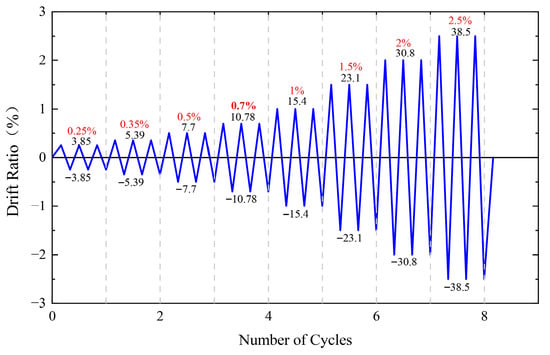
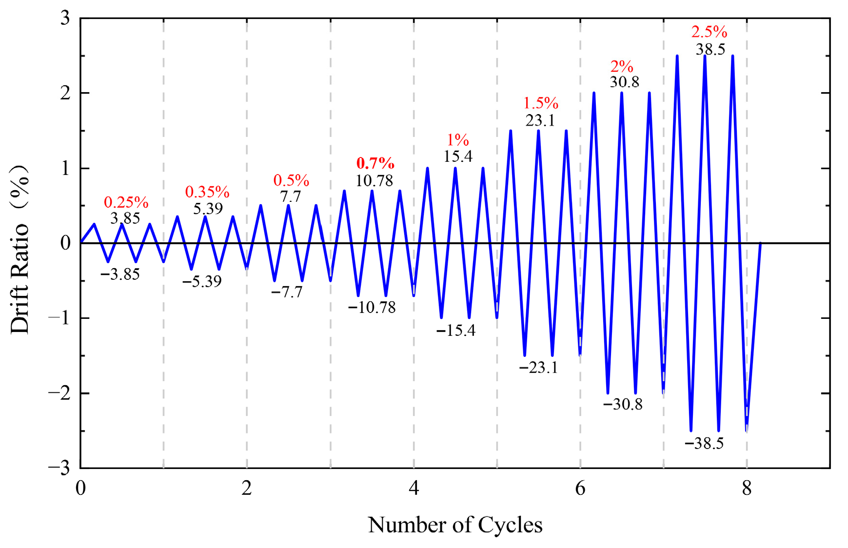
The experimental loading protocol is illustrated in Figure 7. The loading protocol comprised 8 distinct displacement amplitudes (drift ratios), with each amplitude repeated for 3 full cycles. This displacement-controlled loading protocol was established with reference to commonly adopted quasi-static cyclic loading procedures for timber lateral-force-resisting systems, as well as to previous experimental studies on self-centering timber joints [23]. The target inter-story drift ratios were 0.25%, 0.35%, 0.5%, 0.7%, 1.0%, 1.5%, 2.0%, and 2.5%, respectively. The relatively refined drift increments in the small-deformation range were selected to better capture the stiffness transitions associated with joint opening and slab cracking, while the repeated cycles at each drift level were intended to reflect stiffness degradation and damage accumulation under reversed loading. The drift ratio was defined as the horizontal displacement at the loading point divided by the height from the loading point to the column base.
Figure 7.
Loading protocol.
With regard to the sign convention, displacement applied by the actuator when pushing the column from right to left was defined as positive, whereas displacement applied when pulling the column from left to right was defined as negative.
4.4. Test Conditions
Based on the aforementioned specimens, cyclic loading tests were conducted to investigate the effect of slab presence. The test matrix is presented in Table 2, where FPT,0 denotes the total initial post-tensioning force in the two steel strands, and T represents the torque applied to the friction bolt using a torque wrench.
Table 2.
Test matrix.
Specimens P70-N25-S (with slab) and P70-N25-N (without slab) were subjected to cyclic loading in accordance with the loading protocol described above, representing post-tensioned self-centering timber frames with and without a concrete slab, respectively.
4.5. Test Results and Analysis
4.5.1. Analysis of Failure Modes
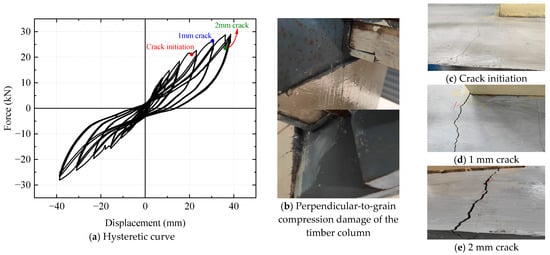
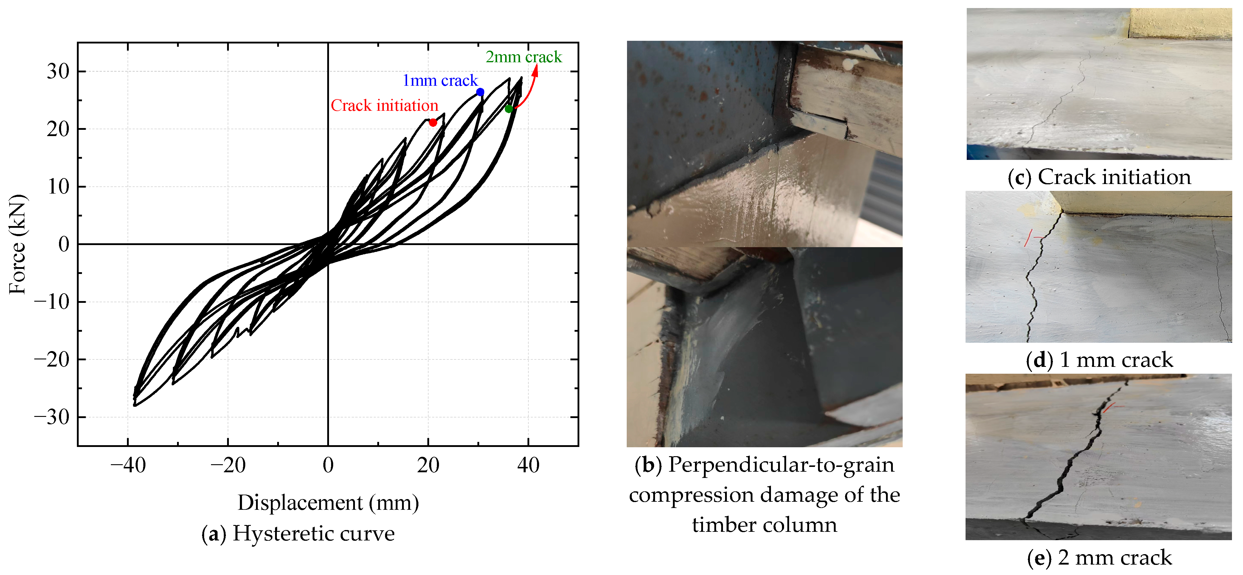
Figure 8 presents the overall hysteretic curves for test conditions P70-N25-S. These curves directly illustrate the deformation characteristics and damage evolution of the post-tensioned self-centering timber frame under low-cycle reversed loading. The primary deformation and damage modes were compressive indentation of the timber column at the beam-column interface and cracking of the reinforced concrete slab. During the initial loading stage, the hysteretic curve exhibited an abrupt transition from a steep slope to a flatter response, forming a pronounced knee point. This behavior is attributed to the low transverse compressive strength of timber, which causes indentation of the timber column to become the dominant initial damage mode. As shown in Figure 8b, clear local indentation of the timber column was observed at the beam-column contact region under cyclic loading. The resulting local plastic deformation of the timber column under perpendicular-to-grain compression produced an irreversible gap at the beam-column contact interface, leading to the first reduction in structural stiffness. The local damage shown in Figure 8b provides direct evidence of this deformation mechanism. In addition, the hysteretic loops exhibited a certain degree of asymmetry between the tension and compression sides. This asymmetry is likely related to the non-uniform development of local indentation damage of the timber column during reversed loading, as illustrated in Figure 8b. On the damaged side, the load path had to first overcome the contact gap at the interface, resulting in a slower increase in load. By contrast, the opposite side remained in a relatively more favorable mechanical condition, leading to a noticeably steeper slope of the hysteretic curve. On the damaged side, the load path had to first overcome the contact gap at the interface, resulting in a slower increase in load. By contrast, the opposite side remained in a more favorable mechanical condition, leading to a noticeably steeper slope of the hysteretic curve. As loading progressed into the intermediate and later stages, corresponding to the large-deformation range, the combined effects of slab cracking and timber column damage further altered the shape of the hysteretic loops. When the drift ratio reached 1.5%, initial cracking appeared on the top surface of the slab near the loading point, as shown in Figure 8c. At this stage, numerous local abrupt changes were observed in the hysteretic loops of the frame. As the drift ratio increased further, the cracks continued to propagate. At a drift ratio of 2.0%, the crack width reached 1 mm, as shown in Figure 8d, and at the maximum drift ratio it increased to 2 mm, as shown in Figure 8e. The cracks mainly propagated from the joint region toward the slab edges. Throughout the loading process, the stiffness of the hysteretic curves gradually degraded, accompanied by the progressive development of a pinching effect. These phenomena can be attributed to the progressive cracking of the concrete slab during cyclic loading.
Figure 8.
Hysteresis curves and representative failure modes of specimen P70-N25-S.
From the perspective of structural damage evolution, the early-stage stiffness degradation and asymmetric deformation are mainly governed by the local indentation of the timber column under transverse compression, as shown in Figure 8b, which leads to the first stiffness transition. The resulting knee point and the asymmetry of the hysteretic loops can therefore be regarded as key indicators of initial damage. In contrast, slab cracking governs the continued stiffness degradation and the enhancement of energy dissipation in the intermediate and later stages, typically manifested by a pinching effect in the hysteretic loops, corresponding to the transition into Phase III. This staged damage progression and its correspondence with distinct hysteretic features are closely related to the constitutive characteristics of timber, which undergoes plastic deformation, and concrete, which exhibits brittle cracking. This failure progression is broadly consistent with previous studies on self-centering timber systems, in which local timber compression damage, joint opening, and frictional sliding were also identified as key factors governing hysteretic behavior [13,16,23]. However, compared with slab-free self-centering timber joints, the present specimen exhibited an additional response transition associated with slab cracking, which further modified the stiffness degradation pattern and the pinching response. This indicates that, in slab-participating self-centering timber frames, the slab should be regarded not only as a stiffness-enhancing component but also as a damage-sensitive resisting component whose contribution evolves during cyclic loading.
4.5.2. Stiffness Variation and Degradation
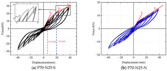
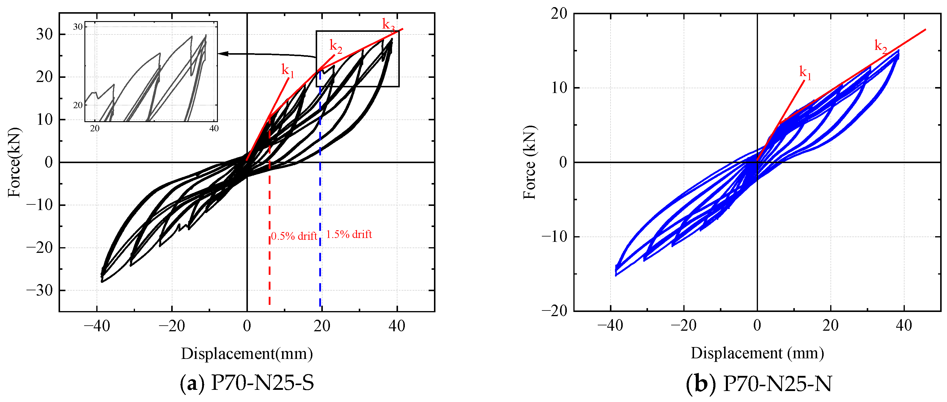
As shown in Figure 9a, the initial stiffness of specimen P70-N25-S before joint opening, corresponding to Phase I, was 1.537 kN/mm. The joint opened at a drift ratio of approximately 0.5%, resulting in an abrupt reduction in stiffness. Thereafter, the post-opening stiffness continued to evolve with increasing drift amplitude, which is consistent with the theoretical analysis presented in Section 3. Based on the preceding analysis, after joint opening, the contribution of the slab to structural stiffness gradually developed and then progressively diminished, thereby dividing the mechanical response into three distinct phases. The corresponding stiffness values, denoted as k2 and k3, were calculated as 0.817 kN/mm and 0.410 kN/mm, respectively (Table 3). When the drift ratio reached about 1.5%, the post-opening stiffness transitioned from k2 to k3, accompanied by noticeable cracking of the slab and a significant sudden change in the hysteretic curve, as illustrated in Figure 8.
Figure 9.
Stiffness Variation Across Loading Cases.
Table 3.
Stiffness variation under different loading conditions.
As shown in Figure 9a, once the drift ratio of specimen P70-N25-S exceeded 0.5%, the hysteretic loops in the second and third cycles exhibited noticeable stiffness degradation compared with those in the first cycle at the same drift amplitude. For example, at drift ratios between 2.0% and 2.5%, the first cycle consistently exhibited higher column-end loads and greater stiffness under the same displacement, as shown in the inset of Figure 9a. This phenomenon is attributed to the progressive damage of the slab under cyclic loading. Even minor accumulated damage can reduce the load-carrying capacity and stiffness of the structure at the same loading amplitude.
The hysteretic curve of specimen P70-N25-N is shown in Figure 9b. The initial stiffness and post-opening stiffness, corresponding to Phase I and Phase II, were 0.848 kN/mm and 0.282 kN/mm, respectively. Both specimens, P70-N25-S and P70-N25-N, experienced joint opening at a drift ratio of approximately 0.5%, marking the first stiffness transition. The initial stiffness of P70-N25-S was 81.25% higher than that of P70-N25-N, indicating that the presence of the slab effectively enhanced the initial stiffness of the frame under the tested configuration. Furthermore, the post-opening stiffness of P70-N25-S remained significantly higher than that of P70-N25-N, with an increase of 189%. Even after slab cracking and progressive damage, the stiffness of P70-N25-S still slightly exceeded the post-opening stiffness of the slab-free specimen. This indicates that the slab continued to make a substantial contribution to the secondary stiffness of the structure after cracking and before complete failure. Moreover, even after significant slab damage, the reinforcing steel within the slab remained partially engaged, thereby maintaining an overall structural stiffness greater than that of the slab-free frame.
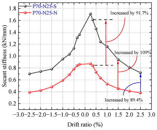
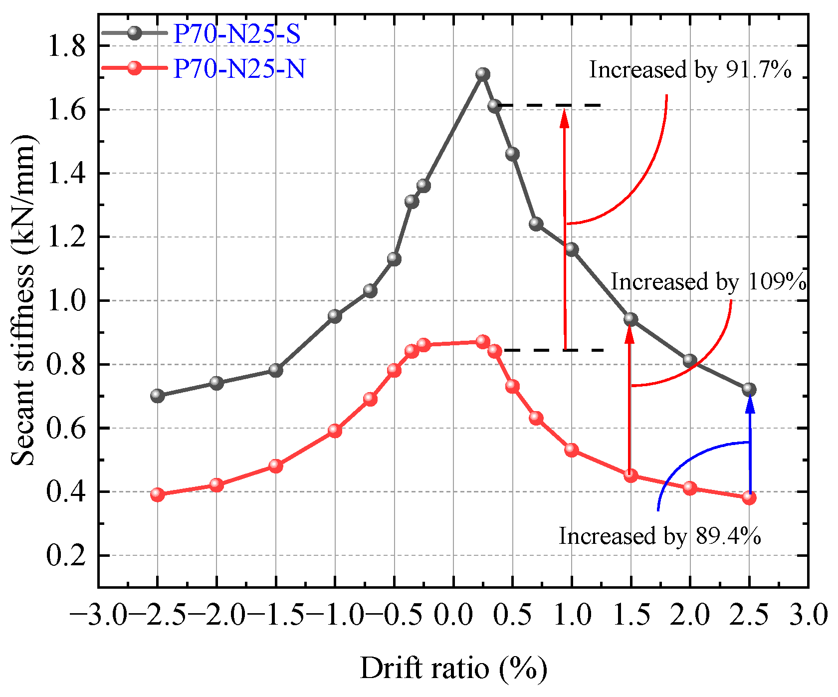
To further illustrate the influence of the slab on structural stiffness, the secant stiffness, Ks, was introduced as a supplementary stiffness index and defined as the lateral force at the target point divided by the corresponding lateral displacement at the loading point. Figure 10 presents a comparative evaluation of the secant stiffness at each drift level for all test conditions, thereby illustrating the stiffness degradation characteristics under different loading cases. The corresponding numerical values and increase ratios are summarized in Table 4. As shown in Figure 10, the secant stiffness of P70-N25-S gradually decreased with increasing drift ratio, whereas specimen P70-N25-N consistently exhibited lower secant stiffness than P70-N25-S at all drift levels. Several conclusions can be drawn. First, the presence of the slab effectively enhances structural stiffness, with this enhancement primarily manifested in Phases I and II, where the slab-related stiffness increase is most pronounced. For example, at drift ratios of 0.35% and 1.5%, the secant stiffness of P70-N25-S was 91.7% and 109% higher than that of P70-N25-N, respectively. After the drift ratio exceeded 1.5%, slab cracking initiated and progressively developed with increasing loading amplitude, leading to a reduction in the slab’s stiffness contribution. Nevertheless, a noticeable stiffness enhancement remains, as evidenced by the 89.4% increase in secant stiffness of P70-N25-S compared to P70-N25-N at a drift ratio of 2.5%. According to the stage-based analytical model presented in Section 3, the initial stiffness corresponds to Phase I, in which the slab and frame act compositely before significant joint opening occurs; the subsequent stiffness reduction corresponds to Phase II after joint opening; and the further degradation is associated with Phase III after slab cracking. Therefore, the experimentally observed stiffness transitions are in good agreement with the theoretical phase division. These stiffness results are consistent with the general understanding of timber–concrete composite members, in which slab participation can significantly improve the flexural stiffness of timber-based members before major cracking occurs [19]. At the same time, compared with previously reported slab-free self-centering timber systems [13,23], the present results further indicate that slab participation affects not only the initial stiffness but also the post-opening stiffness of the frame. From an engineering perspective, this suggests that neglecting slab participation may lead to an underestimation of the global stiffness and drift control capacity of self-centering timber frames, particularly in the small-to-moderate deformation range.
Figure 10.
Secant Stiffness Across Loading Cases.
Table 4.
Comparison of secant stiffness.
It should be noted that the present study was based on quasi-static cyclic tests; therefore, the fundamental period of the frame was not directly measured for either the slab-participating specimen or the slab-free specimen. In this study, the influence of slab participation on the global structural response was interpreted primarily through stiffness-related indices derived from the cyclic response, including the initial stiffness, post-opening stiffness, secant stiffness, and the characteristic stage-based stiffness transitions.
4.5.3. Load-Carrying Capacity
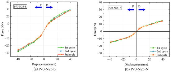
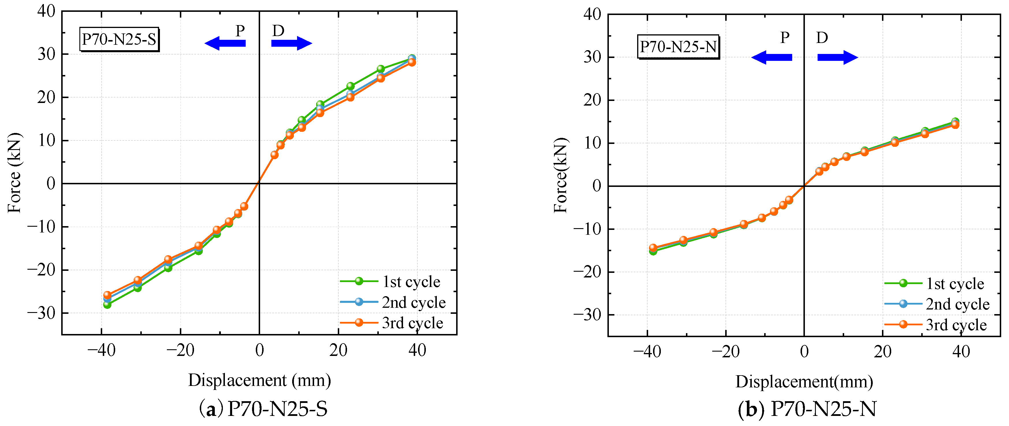
The skeleton curves for specimens P70-N25-S and P70-N25-N are shown in Figure 11. where P represents push and D represents draw. Owing to the observed asymmetry between the push and pull directions, the load-bearing capacity of the frame was defined as the average of the maximum lateral forces in the two directions. As shown in Figure 11a, for specimen P70-N25-S, the load-bearing capacity in the second loading cycle was lower than that in the first cycle, and the extent of this reduction increased with the loading amplitude, although the overall degradation remained limited. Furthermore, the load-bearing capacity in the third cycle did not change significantly compared with that in the second cycle. A similar trend was observed for specimen P70-N25-N, as shown in Figure 11b. This behavior can be mainly attributed to the compression of gaps between components, which occurred primarily during the first loading cycle and resulted in minor post-tensioning loss, thereby reducing the load-bearing capacity. In addition, minor slab cracking in specimen P70-N25-S also contributed to the reduction in load-bearing capacity.
Figure 11.
Skeleton curves of different test scenarios.
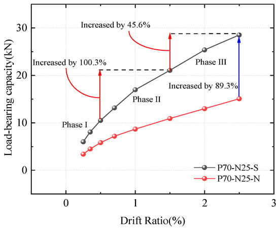
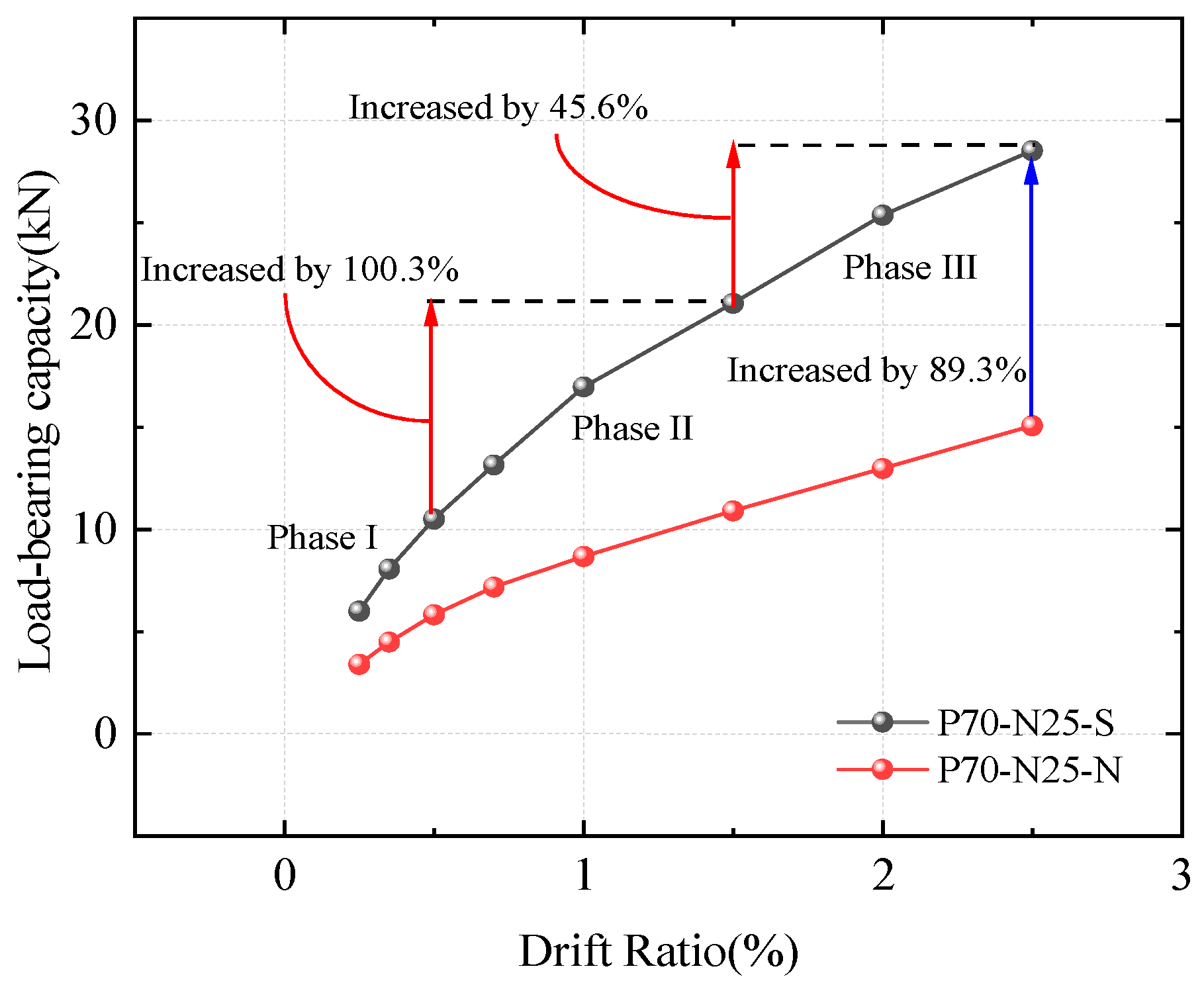
Since the skeleton curves for each specimen showed no significant differences among the three loading cycles, the load-bearing capacity obtained from the first cycle was selected for statistical comparison, as shown in Figure 12. As indicated in Figure 9, changes in structural stiffness occurred at drift ratios of 0.5% and 1.5%, corresponding to the transition points from Phase I to Phase II and from Phase II to Phase III, respectively. For specimen P70-N25-S, the load-bearing capacities at drift ratios of 0.5% and 1.5% were 10.51 kN and 21.06 kN, respectively. By defining the incremental change in load-bearing capacity at each phase relative to the previous phase as ΔF, we obtain . It is evident that this increment is closely related to the change in flexural capacity. Therefore, the flexural capacities corresponding to each phase are presented below for comparative analysis. The expressions for the flexural capacity in each phase are given as follows:
Figure 12.
Comparison of load-carrying capacities.
Based on the expressions above, the increase in load-bearing capacity from Phase I to Phase II can be primarily attributed to the deformation of the PT strands induced by joint opening, as well as the contribution from the deformation of the slab reinforcement. In contrast, the increase from Phase II to Phase III is mainly governed by the PT strands, while the slab still contributes to the load-bearing capacity due to the reduced effective flange width after cracking. However, the proportion of this contribution gradually decreases with increasing deformation. Analysis of the experimental results indicates that the structural load-bearing capacity increased by 100.3% from Phase I to Phase II and by 45.6% from Phase II to Phase III. These trends are generally consistent with those predicted by the theoretical expressions, further indicating that the contribution of the slab to the structural load-bearing capacity is primarily reflected in Phases I and II and the stage-based analytical model can qualitatively interpret the experimentally observed capacity transitions.
Based on the aforementioned theoretical derivation of the hysteresis model for the self-centering timber frame with a slab, the experimental results were compared with the corresponding theoretical predictions. The contributions of friction, post-tensioning, and the slab to the flexural capacity at the beam end were calculated using the theoretical expressions (1–17), as summarized in Table 5. The results show that the slab makes a significant contribution to the structural flexural capacity in Phases I and II. However, in Phase III, slab cracking leads to a reduction in the effective flange width, resulting in an approximately 50% decrease in the slab contribution, as specified in GB 50010. Meanwhile, the contribution of post-tensioning continues to increase with the growing deformation of the strands at larger drift ratios. Consequently, the proportional contribution of the slab is significantly reduced in this phase.
Table 5.
Theoretical Contributions to Load-Bearing Capacity in different phases (Unit: kN·m).
The slab-free specimen P70-N25-N also exhibited a markedly lower load-bearing capacity than specimen P70-N25-S. At the maximum drift ratio, the load-bearing capacity of P70-N25-S was 89.3% higher than that of P70-N25-N, further confirming the substantial contribution of the slab to the load-bearing capacity of the timber frame. The stage-based analytical model also provides a qualitative interpretation of the experimentally observed load-carrying capacity evolution. In particular, the contribution of slab participation is more pronounced before major cracking, while the relative contribution gradually changes after the structure enters the later response stage. This tendency is consistent with the comparison between the theoretical mechanism and the experimental skeleton curves. A similar influence of additional structural components on the stage-wise lateral resistance has also been reported in related self-centering timber and hybrid systems [15,18], although the quantitative slab contribution observed here remains specific to the tested configuration. The detailed load-carrying capacity values and increase ratios are summarized in Table 6.
Table 6.
Comparison of load-carrying capacity values.
4.5.4. Energy Dissipation Capacity
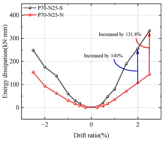
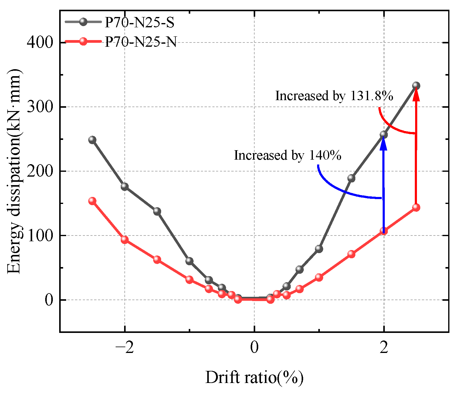
The cumulative energy dissipation for all test conditions was first calculated, as shown in Figure 13, to evaluate the energy dissipation performance of the structure. Comparison of the energy dissipation curves for specimens P70-N25-S and P70-N25-N shows that the former exhibited overall better energy dissipation performance than the latter. When the drift ratio reached 2.0%, the cumulative energy dissipation of P70-N25-S was 140% higher than that of P70-N25-N, and by the end of loading, it remained 131.8% higher. Therefore, it is evident that the presence of the slab effectively enhances the energy dissipation capacity of the structure, indicating a positive contribution to energy dissipation under the present test conditions. The corresponding cumulative energy dissipation values and increase ratios are summarized in Table 7.
Figure 13.
Cumulative Energy Dissipation Comparison.
Table 7.
Comparison of energy dissipation.
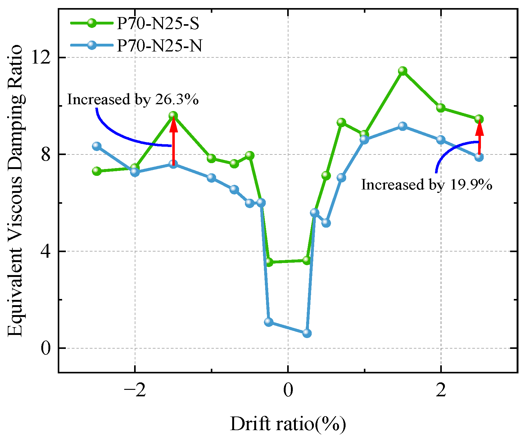
The equivalent viscous damping ratio is another key parameter for evaluating structural energy dissipation performance, and it can be expressed as , where k is the stiffness and X is the displacement amplitude. Figure 14 presents the equivalent viscous damping ratios under various loading cases.
Figure 14.
Equivalent Viscous Damping Ratio.
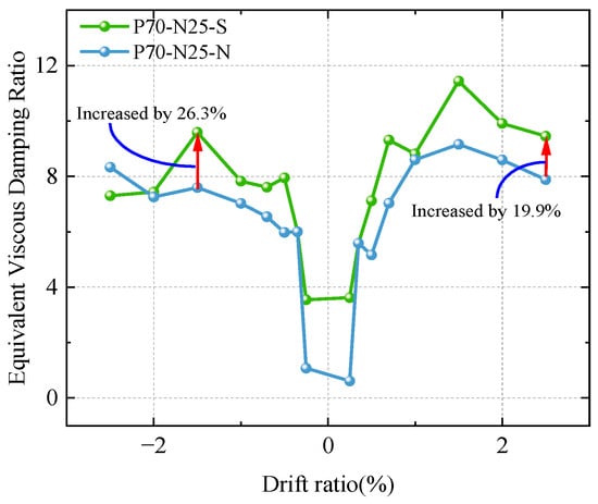
Comparison of the equivalent viscous damping ratios of specimens P70-N25-S and P70-N25-N shows that, within the drift ratio range of −1.5% to 2.5%, the equivalent viscous damping ratio of P70-N25-S was generally higher than that of P70-N25-N. For example, at a drift ratio of −1.5%, the equivalent viscous damping ratio of the former was 26.3% higher than that of the latter, while at a drift ratio of 2.5%, the increase was 19.9%. These results indicate that the presence of the concrete slab contributes positively to the energy dissipation capacity of the structure. The asymmetry observed in the energy dissipation and equivalent viscous damping ratio is mainly attributed to the non-uniform damage development and contact condition at the beam-column interface during cyclic loading. In the early loading stage, local indentation of the timber column under perpendicular-to-grain compression leads to uneven gap development and different resistance characteristics in the two loading directions. After joint opening and slab cracking, the contributions of slab participation, frictional sliding, and restoring action do not evolve in a perfectly symmetric manner, which further modifies the hysteretic loop shape. As a result, the energy dissipation and equivalent viscous damping ratio exhibit a certain degree of asymmetry during the cyclic response. Similar friction-dominated dissipation characteristics were also reported in previous self-centering timber joint studies [13,23], while the present results further suggest that slab participation modifies the energy dissipation process in a stage-dependent manner. The detailed comparison of equivalent viscous damping ratios is summarized in Table 8.
Table 8.
Comparison of equivalent viscous damping ratio.
5. Conclusions
To address the limited understanding of slab effects in existing studies on self-centering timber structures, a comparative experimental program was designed in this study, with the presence or absence of a reinforced concrete slab taken as the key variable. Based on a systematic analysis of the test results, the following main conclusions were drawn:
- (1)
- The failure mode of the post-tensioned self-centering timber frame structure with a slab was mainly characterized by progressive cracking and eventual fracture failure of the concrete slab. No significant damage to the grain was observed in the timber beams, while local compressive indentation occurred at the beam-column interface of the timber columns.
- (2)
- The composite action between the reinforced concrete slab and the timber beam significantly enhanced the load-bearing capacity of the frame. The ultimate load-bearing capacity of the specimen with a slab (P70-N25-S) was 89.3% higher than that of the specimen without a slab (P70-N25-N). Furthermore, provided that the primary members remain undamaged and the prestressing tendons do not yield, appropriate control of the initial prestress may further improve the load-bearing performance of the structure.
- (3)
- The composite action of the slab effectively enhanced the overall stiffness of the structure under the tested configuration. The initial stiffness of the specimen with a slab was 81.25% higher than that of the specimen without a slab, and its secant stiffness remained significantly higher than that of the specimen without a slab at all applied drift ratios. The slab’s contribution to stiffness was primarily concentrated in the elastic stage (Phase I) and the frictional energy dissipation stage (Phase II), where the stiffness enhancement was most pronounced (e.g., an increase of 91.7% at a drift ratio of 0.35% and 109% at 1.5%). Even after the slab cracked (drift ratio > 1.5%), its influence on stiffness remained noticeable (an 89.4% increase at a drift ratio of 2.5%).
- (4)
- The slab significantly enhanced the energy dissipation capacity of the structure under the present test conditions. The maximum cumulative energy dissipation of the specimen with a slab (P70-N25-S) was more than double that of the specimen without a slab (P70-N25-N).
It should be noted that this study is based on two full-scale comparative specimens and is intended as a mechanistic investigation of slab participation, rather than a generalized parametric design study. Meanwhile, because the present work focuses on quasi-static cyclic behavior, the dynamic characteristics of the system, such as the fundamental period and modal properties with and without slab participation, were beyond the scope of the current experimental program. Future studies should include additional full-scale specimens with different slab thicknesses, reinforcement ratios, connector layouts, and initial post-tensioning levels. In addition, vibration-based tests, shaking-table tests, and refined numerical models incorporating damage indices should be conducted to further clarify the dynamic response, damage evolution, and design applicability of slab-participating self-centering timber frames, thereby providing a more complete evaluation of slab effects on the global stiffness and seismic response of self-centering timber frames.
Author Contributions
Conceptualization, Y.X. and L.H.; Validation, F.Y.; Writing, Y.X., F.Y. and L.H.; Formal analysis, C.T.; Investigation, F.Y.; resources, L.H.; Data curation, Y.X. and F.Y. All authors have read and agreed to the published version of the manuscript.
Funding
The research described in this paper was sponsored by the National Natural Science Foundation (52508577), Nanjing Forestry University Undergraduate Innovation Training Program (202410298031Z), the Natural Science Foundation of Jiangsu Province (BK20250219).
Data Availability Statement
The original contributions presented in this study are included in the article. Further inquiries can be directed to the corresponding author.
Conflicts of Interest
The authors declare no conflicts of interest.
References
- Du, H.; Liu, P.; Yuan, S.; Wei, Y. Slip modulus of inclined screw connectors in glued laminated bamboo and wood-concrete composite beams. Wood Mater. Sci. Eng. 2025, 20, 1204–1215. [Google Scholar] [CrossRef] [Scilit]
- Liu, P.; Du, H.; Chen, Z.; Hu, X. Review of long-term performance of timber-concrete composite beam. Bioresources 2025, 20, 2374–2390. [Google Scholar] [CrossRef] [Scilit]
- Zhang, Y.; Zhang, J.; Zhang, J.; Zheng, K.; Wei, Y. Comparative analysis of seismic response and vulnerability of laminated bamboo frame structure under near-field and far-field earthquake actions. Structures 2024, 69, 107321. [Google Scholar] [CrossRef] [Scilit]
- Filiatrault, A. Analytical predictions of the seismic response of friction damped timber shear walls. Earthq. Eng. Struct. Dyn. 1990, 19, 259–273. [Google Scholar] [CrossRef] [Scilit]
- Loo, W.Y.; Quenneville, P.; Chouw, N. A numerical study of the seismic behaviour of timber shear walls with slip-friction connectors. Eng. Struct. 2012, 34, 233–243. [Google Scholar] [CrossRef] [Scilit]
- Loo, W.Y.; Kun, C.; Quenneville, P.; Chouw, N. Experimental testing of a rocking timber shear wall with slip-friction connectors. Earthq. Eng. Struct. Dyn. 2014, 43, 1621–1639. [Google Scholar] [CrossRef] [Scilit]
- Loo, W.Y.; Quenneville, P.; Chouw, N. Rocking timber structure with slip-friction connectors conceptualized as a plastically deformable hinge within a multistory shear wall. J. Struct. Eng. 2016, 142, E4015010. [Google Scholar] [CrossRef] [Scilit]
- Hashemi, A.; Masoudnia, R.; Quenneville, P. Seismic performance of hybrid self-centring steel-timber rocking core walls with slip friction connections. J. Constr. Steel Res. 2016, 126, 201–213. [Google Scholar] [CrossRef] [Scilit]
- Hashemi, A.; Zarnani, P.; Quenneville, P. Seismic assessment of rocking timber walls with energy dissipation devices. Eng. Struct. 2020, 221, 111053. [Google Scholar] [CrossRef] [Scilit]
- Tatar, A.; Dowden, D.M. Analytical and numerical investigation of a low-damage uplift friction damper for self-centering cross-laminated timber rocking walls. Eng. Struct. 2022, 254, 113836. [Google Scholar] [CrossRef] [Scilit]
- Li, Z.; Chen, F.; Dong, H.; He, M.J.; Li, M.H. Lateral performance of timber-steel hybrid shear wall with friction dampers under cyclic loading. J. Build. Struct. 2020, 41, 1–10. [Google Scholar]
- Li, Z.; Chen, F.; He, M.; He, G. Self-centering steel-timber hybrid shear wall: Experimental research on the lateral performance and the parametric analysis on the self-centering performance. China Civ. Eng. J. 2021, 8, 14–23. [Google Scholar]
- Ding, Y.; Zhou, Z.; Huang, L.; Si, Y. Seismic performance of self-centering glulam frame with friction damper. Eng. Struct. 2021, 245, 112857. [Google Scholar] [CrossRef] [Scilit]
- Lepine-Lacroix, S.; Yang, T.Y. Seismic design and performance evaluation of novel dual-pinned self-centering coupled CLT shear walls. Eng. Struct. 2023, 279, 115547. [Google Scholar] [CrossRef] [Scilit]
- Wang, X.; Li, Z.; Xie, P.; He, M. Seismic assessment of glulam frames with dual-tube self-centering buckling-restrained braces. J. Build. Eng. 2024, 97, 110753. [Google Scholar] [CrossRef] [Scilit]
- Huang, L.; Hu, J.; Zeng, B.; Wei, Y.; Zhou, Z. Investigation on the failure mechanism of friction-based self-centering timber beam-column joint considering bolt bearing effect: Experimental study and theoretical analyses. J. Build. Eng. 2024, 98, 110974. [Google Scholar] [CrossRef] [Scilit]
- Ho, T.X.; Barbosa, A.R.; Simpson, B.; Sinha, A. Design and Cyclic Testing of a Full-Scale Three-Story Mass Timber Structure with Post-Tensioned Self-Centering Rocking Walls. J. Build. Eng. 2025, 115, 114505. [Google Scholar]
- Li, Z.; Chen, F.; Li, M.; Lam, F.; He, M. Experimental investigation into the lateral performance of post-tensioned steel-timber hybrid frame with tension-only braces. Eng. Struct. 2025, 325, 119390. [Google Scholar] [CrossRef] [Scilit]
- Chen, F.; Li, M.; Li, Z. Self-centering mass timber structures: A review on recent research progress. Eng. Struct. 2024, 303, 117474. [Google Scholar] [CrossRef] [Scilit]
- Froozanfar, M.; Moradi, S.; Kianoush, R.; Speicher, M.S.; Di Sarno, L. Review of self-centering rocking systems for earthquake-resistant building structures: State of the art. J. Build. Eng. 2024, 84, 108607. [Google Scholar] [CrossRef] [Scilit]
- Shi, B.; Zhou, X.; Tao, H.; Yang, H.; Wen, B. Long-Term Behavior of Timber–Concrete Composite Structures: A Literature Review on Experimental and Numerical Investigations. Buildings 2024, 14, 1770. [Google Scholar] [CrossRef] [Scilit]
- Nerilli, F.; Ahmadi, H.M.; Imperatore, S.; Vairo, G. Bond–Slip Performance of GFRP Rebars in Concrete Under Alkaline and Thermal Conditioning. J. Compos. Sci. 2026, 10, 131. [Google Scholar] [CrossRef] [Scilit]
- Shi, B.; Zhu, W.; Yang, H.; Liu, W.; Tao, H.; Ling, Z. Experimental and theoretical investigation of prefabricated timber-concrete composite beams with and without prestress. Eng. Struct. 2020, 204, 109901. [Google Scholar] [CrossRef] [Scilit]
- GB 50010-2010; Code for Design of Concrete Structures. China Architecture & Building Press: Beijing, China, 2011.
- GB/T 50329—2012; Standard for Test Methods of Timber Structures. China Architecture & Building Press: Beijing, China, 2012.
- GB/T 26899—2011; Glued Laminated Timber for Structural Purposes. China Standards Press: Beijing, China, 2011.
- Huang, L.; Zhou, Z.; Liu, H.; Si, Y. Experimental investigation of hysteretic performance of self-centering glulam beam-to-column joint with friction dampers. J. Earthq. Tsunami 2021, 15, 215. [Google Scholar] [CrossRef] [Scilit]

Disclaimer/Publisher’s Note: The statements, opinions and data contained in all publications are solely those of the individual author(s) and contributor(s) and not of MDPI and/or the editor(s). MDPI and/or the editor(s) disclaim responsibility for any injury to people or property resulting from any ideas, methods, instructions or products referred to in the content. |
© 2026 by the authors. Licensee MDPI, Basel, Switzerland. This article is an open access article distributed under the terms and conditions of the Creative Commons Attribution (CC BY) license.