


Abstract
Complex environments, such as underground pipe galleries, subway tunnels, and bridge piles, seriously affect the construction of underground passages. Reducing the disruption of the surrounding environment and road traffic during the construction of underground passages in urban transportation hubs is very important for underground passages. Overcoming these difficulties is a problem that we constantly strive to solve. In this paper, we innovatively propose an open-shield construction method (OSM) without a support structure. It simplifies the construction process, is very adaptable to low soil cover depth and complex construction environments, and has minimal impact on traffic disruption during construction. We first analyze the main problems in the construction of urban underground passages and then elaborate on the OSM in detail. Then, an example of an actual project is used to explain the requirements for prefabricated pipe segments and the waterproof structure. Finally, the effect of applying this method is evaluated by using numerical simulation technology and actual monitoring data. This method provides practical engineering application references for the construction of urban underground passages.
1. Introduction
With the advancement of urbanization in China, the urban population is gradually increasing and becoming increasingly dense. To increase space for activities, engineering construction projects are gradually developing underground infrastructure. The most prominent examples of these projects include foundation-pit and tunnel engineering. The construction and utilization of underground space facilitate travel and allow people to go about their daily lives. For instance, the construction of some underground pedestrian passages can effectively alleviate urban traffic congestion [1,2,3,4,5]. However, during the construction of underground spaces in some cities, complex surrounding geological environments are often encountered, affecting the construction of underground utility tunnels, bridge piles, metro tunnels, etc., thereby creating a series of difficulties for the construction of underground passages [6,7,8,9].
The complex geological conditions encountered during underground-space construction are highly detrimental to these projects and can easily lead to a series of engineering accidents. There are strict requirements for the stability of the construction and the waterproofing of the structures, and many scholars have researched the construction of urban underground spaces. Yang et al. [10] used three-dimensional numerical software to simulate the process of groundwater seepage and excavation based on a subway station foundation pit project, studying groundwater seepage, the deformation of the supporting structure, and surface subsidence affected by spatial effects. Yin et al. [11] proposed a GWO-VMD-LSTM hybrid prediction model to predict the settlement monitoring data of four typical points around the foundation pit of Yongning Hospital in Taizhou, China. Xu et al. [12] investigated the deformation response of a neighboring but not simultaneously constructed foundation pit in Shenzhen. They showed that staged excavation would lead to significant asymmetric deformation, and verified this finding through numerical simulation. Sun et al. [13] adopted the method of using pipe canopy and anti-pull-out piles, and they designed an underground passage using a prefabricated box culvert construction scheme, effectively controlling the bulging and convergence deformation of the tunnel. Chen et al. [14] found that the combination of bored cast-in-place piles, water-stop curtains, and horizontal internal supports significantly controlled the deformation of an adjacent rectangular underground passage. Li et al. [15] found that pre-remolding of the base can effectively control the uneven deformation and overall settlement of underground passages. Additionally, the underground passage was found to enhance the overall stiffness of the stratum and improve its ability to resist partial settlement deformation.
With the advancement of technology, certain prefabricated structures are now frequently being used in underground engineering, especially in the construction of underground passages and tunnels. The most critical issues affecting these prefabricated structures often revolve around waterproofing, especially at the joints, where problems frequently occur [16]. The performance, durability, and types of sealing materials often play significant roles in ensuring segments are waterproofed [17,18]. Yu et al. [19] designed a new type of sealing gasket to be installed at the interface of the segmented bolt holes, and studied the factors affecting the waterproofing performance of the new gasket through numerical analysis. Huang et al. [20] conducted a water- and heat-accelerated-aging test of an ethylene–propylene–diene rubber gasket under compression and revealed a significant reduction in the gasket’s height and degradation of its mechanical properties. Hu et al. [21] studied the contact stress distribution and ultimate deformation conditions of a sealing pad under different joint deformation conditions through compression deformation tests and corresponding numerical simulations.
In summary, numerous studies have been conducted on the construction of underground passages. However, so far, research mainly focuses on support during the construction of underground passages and rarely considers how the impact of excavation support on urban traffic can be reduced during the construction process. Currently, the commonly used methods in underground engineering construction are the cut-and-cover, the shallow tunneling, and the traditional shield methods [22,23,24]. Due to the presence of numerous close-range underground pipelines, bridge piers, and power tunnels at the site of the construction of the underground passage at Nanjing Xinzhuang Interchange Bridge, if the cut-and-cover method is adopted, the pipelines will need to be relocated, which will have a significant impact on surface deformation, and support structures will be required, resulting in traffic disruption, which will have a significant impact on urban traffic, so this method is not optimal. Additionally, the shallow tunneling method is not the best approach either. Thus, in this paper, we innovatively propose using the OSM for the construction of the underground passage at Nanjing Xinzhuang Interchange Bridge. Compared with the pipe-jacking method and traditional construction methods, this approach features a one-third to one-fifth reduction in the thickness of the soil cover, a one-third to one-fourth decrease in ground subsidence, a minimal impact on surrounding tunnels and bridge piers, and the ability to be implemented in narrow spaces for construction. This method also enables traffic to resume during the day and allows for construction at night, and no additional supporting structures are required. Through research on key technologies during construction, numerical simulation, and on-site monitoring, this paper investigates the effect of applying this method and provides scientific examples useful for carrying out similar urban underground passage projects.
2. The Construction of Urban Underground Passages
2.1. The Features of the Urban Underground Passages
Urban underground passages are mainly designed for pedestrian use. Underground passages are narrow and elongated, and their cross-sections are often horseshoe-shaped or rectangular. The thickness of the overlying soil on the passage is generally 3 to 5 m, and the height is usually 4 to 6 m. Due to their shallow burial, they are prone to being affected by ground traffic or other additional loads. If the groundwater level is high, they are also susceptible to the influence of groundwater. There are strict requirements for underground passages regarding the mechanical properties and anti-seepage performance of the segments. Generally, the shield segments should be not less than C50. If a lining structure is adopted, the strength of the secondary lining needs to reach C30 or above, and the anti-seepage strength should be no less than P8.
2.2. Environmental Characteristics of Urban Underground Passages
Since urban underground passages are designed to address issues relating to insufficient ground space for urban transportation, such as traffic congestion caused by heavy pedestrian and vehicle flows, enhancing the speed of pedestrian and vehicle movement and ensuring traffic safety are the main goals of establishing underground passages. The construction sites are often located at urban transportation hubs, and there are usually commercial areas around them. Generally, there are also pieces of infrastructure such as bridges, different functional pipeline tunnels, and subway tunnels, as well as buildings around them. Determining how to minimize disturbance of these external structures or buildings as much as possible is the key to the construction of underground passages.
2.3. The Methods of Constructing Urban Underground Passages
There are various ways of constructing underground passages, including the open-cut, underground excavation, covered excavation, and shield methods. Different construction methods have different requirements for the stability of the surrounding ground as well as the side walls and bottom of the passage during the construction process. The main techniques include using maintenance structure support technology, shotcrete and anchor support, and some temporary support technologies. These technologies are critical for the safe construction of underground passages, the protection of surrounding buildings, and infrastructure safety. However, there are also some problems, such as disturbance during ultra-close-range construction, construction costs, and social impacts. Determining how to solve these problems is critical for the construction of urban underground passages.
3. OSM
3.1. Introducing the OSM
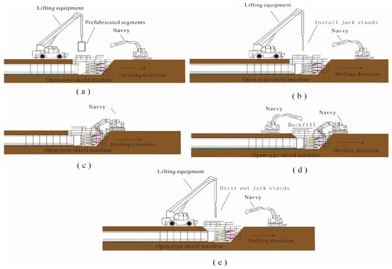
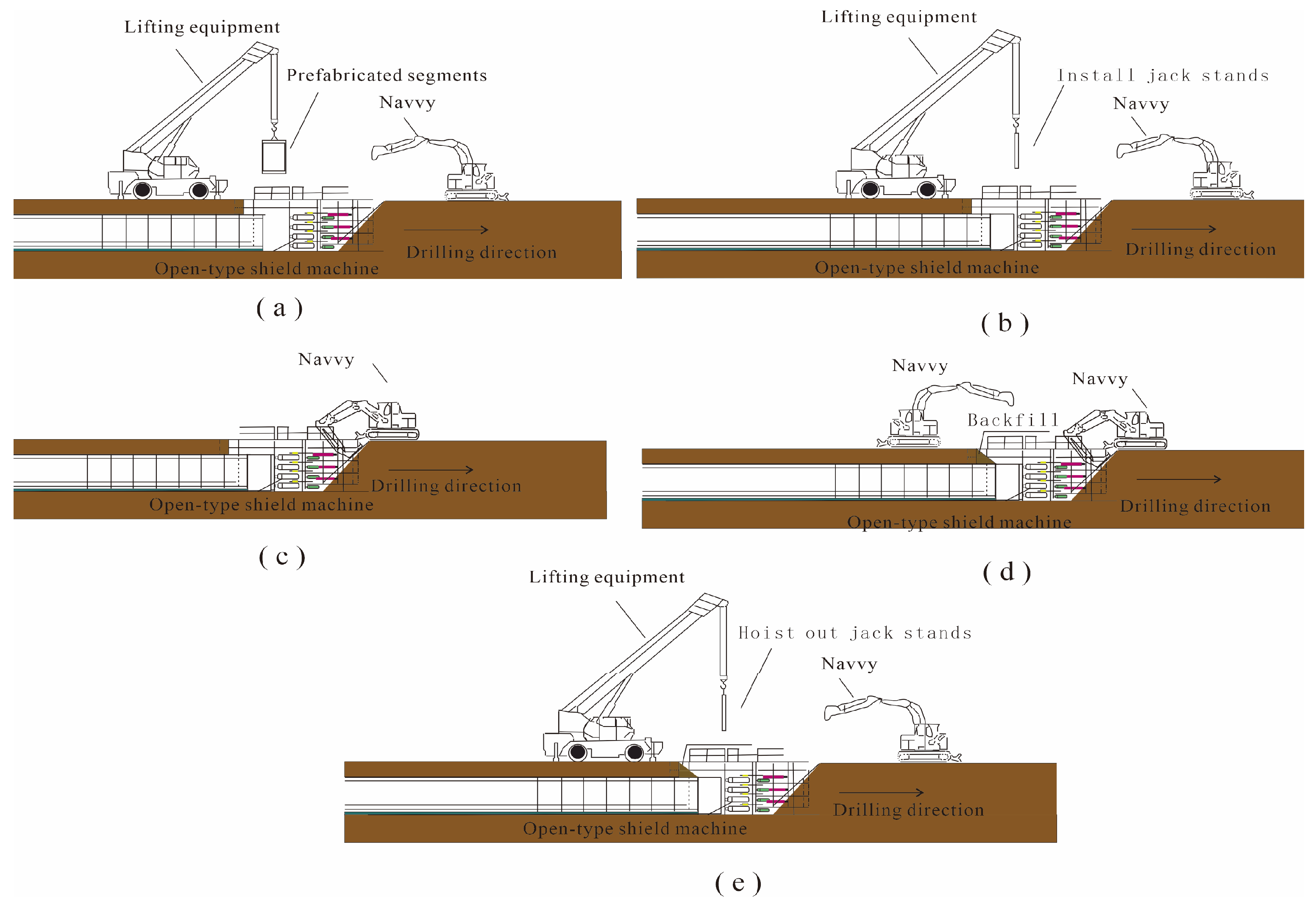
The current techniques for constructing underground passages often require the use of support or maintenance structures, such as internal supports and pile structures. Constructing these structures imposes strict space limitations and can also disturb surrounding structures. Accordingly, we introduce the OSM, whose advantages include a short construction time, low cost, and the ability to be carried out in limited space. Additionally, it is a sustainable and green construction method. It mainly consists of the following steps: (a) First, the prefabricated-component section is installed. The prefabricated components are transported to the vicinity of the OSM shield machine by trucks and then lifted and installed at the preset positions using cranes for assembly. (b) Then, the top anchor is installed, and grouting is performed simultaneously. The top iron is temporarily installed between the prefabricated component and the shield oil cylinder. The top iron is then used to transfer the thrust from the shield oil cylinder to the prefabricated components. (c) Subsequently, the shield machine advances, excavating soil in front and conducting secondary synchronous grouting. (d) Soil is then backfilled behind the shield machine. In this step, the excavator digs into the rock and soil inside the cut section and the overlying soil covering the prefabricated components. The upper soil layer of the prefabricated components is laid out and compacted layer by layer using an excavator. (e) Then, the top iron is removed, and the crane lifts the tie-iron between the prefabricated components and the shield cylinder off the ground. (f) Finally, the next prefabricated component is installed. This method offers excellent advantages in the execution of open-cut shallow-buried underground projects. It can be applied in environments where there are buildings nearby, the surrounding strata are weak, traffic diversion is difficult, and the construction period has strict requirements. Figure 1 shows the construction process.
Figure 1.
Application of the OSM. (a) Hoisting of prefabricated components. (b) Installation of jack stands. (c) Advancement of the shield machine. (d) Soil backfilling. (e) Removal of the top iron.
3.2. Comparison of the Different Construction Methods
The OSM without a supporting structure is innovative in terms of both the construction method and the design of the shield machine. It is also highly adaptable to the soil layer. In what follows, we present an analysis based on the technical indicators and characteristics of the soil layer’s adaptability. The technical indicators include the minimum soil cover depth of each construction method, ground settlement control, adjacent-structure-protection requirements, and requirements regarding the relocation of small-spacing pipelines. The adaptability of the soil is compared with respect to the aspects of the soft clay soil layer, water-rich sandy layer or sand–gravel layer, composite soil layer with varying hardness, and ultra-shallow buried soil layer, as shown in Table 1 and Table 2.
Table 1.
Comparison of the OSM with traditional methods in terms of performance.
Table 2.
Comparison of the OSM with traditional methods in terms of adaptability.
4. Engineering Applications
4.1. Project Profile
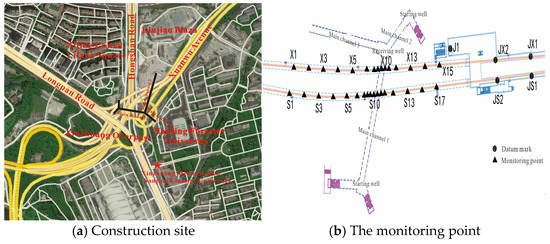
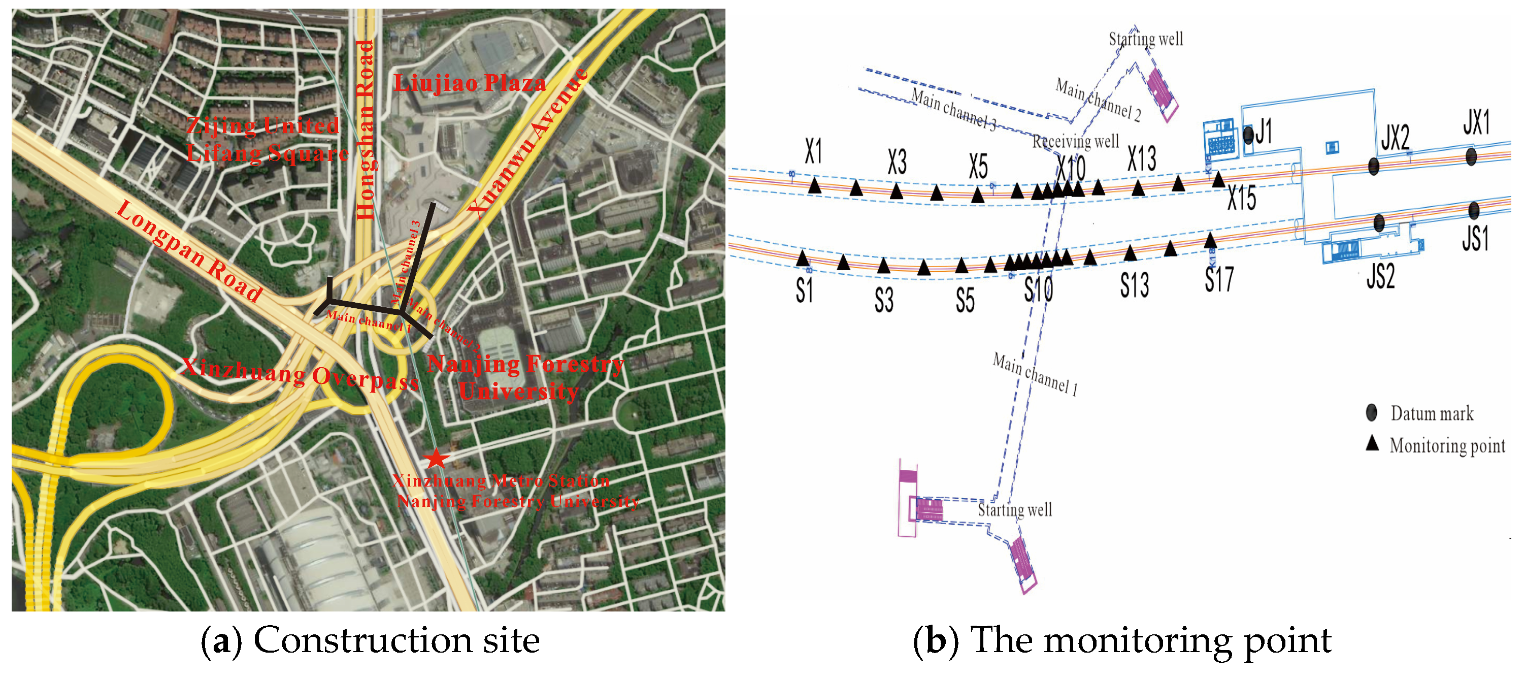
The Xinzhuang Interchange serves as the northeastern hub of Nanjing’s grid-like rapid inner-ring road. It is the intersection of major traffic arteries and serves as the core of travel circulation. The main passage passes under Xuanwu Avenue and Hongshan Road, connecting Zijin United Lifang Square, Nanjing Forestry University, and Liujiao Plaza. The project is shown in Figure 2a, and the monitoring points during construction are shown in Figure 2b.
Figure 2.
Project overview.
4.2. Prefabricated-Segment-Waterproofing Technology
4.2.1. Prefabricated-Segment Requirements
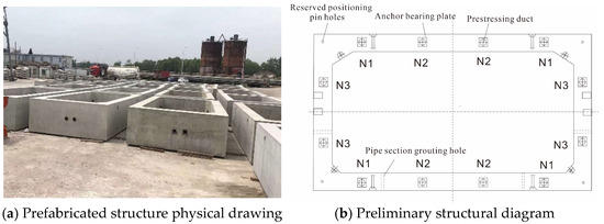
The prefabricated segment is made of waterproof concrete, with a strength grade of no less than C50 and a waterproof grade of no less than P8. The dimensions are 6.9 m × 3.9 m. Prefabricated channels should incorporate holes, reserved reinforcing bars, and other pre-installed components, such as lifting holes and grounding holes, as shown in Figure 3. The number and positions of the reserved holes should be precise, and the exposed reinforcing bars should be protected from bending. The exposed installed components and metal parts should be treated to prevent corrosion and rusting. During the assembly of the prefabricated pipe sections, the thickness and flatness of the concrete base layer should be ≥100 mm and ≤±3 mm, respectively. The underground-passage pipe sections need to be assembled as the excavation progresses. At the same time, longitudinal prestressed reinforcing bars should be tensioned, and top-plate backfilling should be completed. For the outer sides of the shield pipe segments, plain concrete backfilling should be used, while for the inner sides of the pipe sections, temporary weight blocks should be used for weighting.
Figure 3.
Diagram of the prefabricated structure.
4.2.2. Waterproofing the Structure
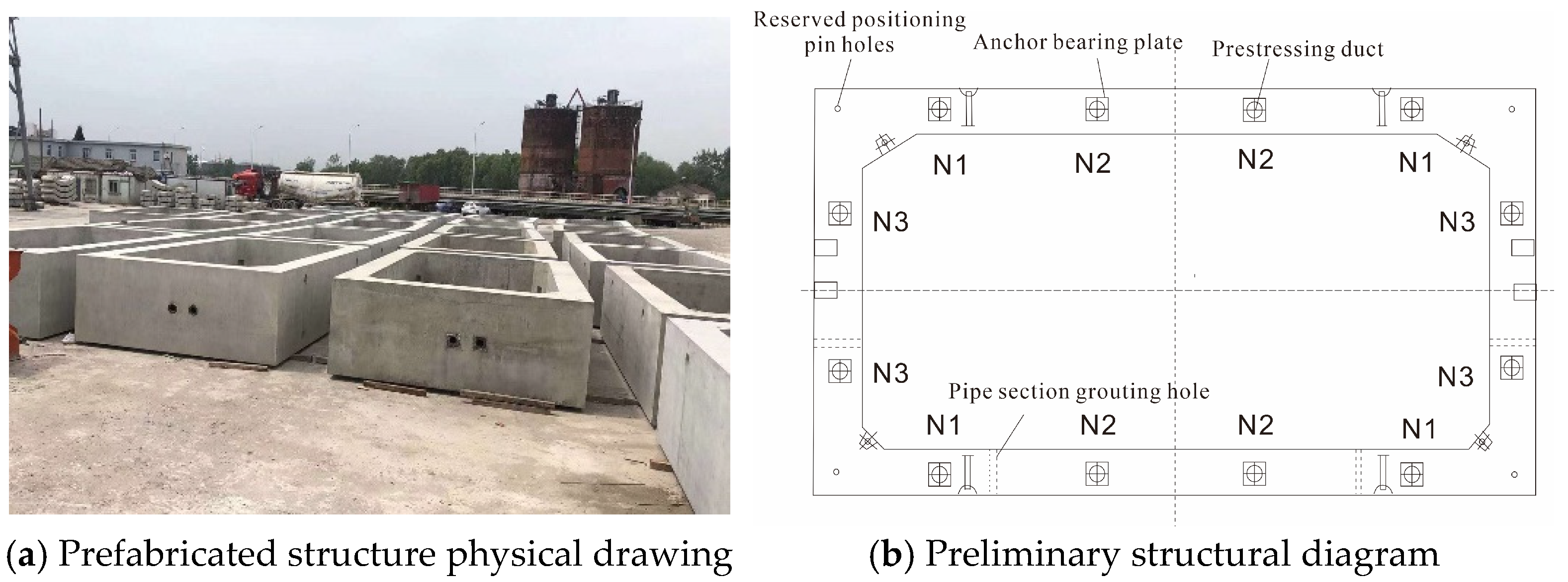
Waterproofing passages and preventing seepage within them are consistently the main problems affecting the construction of underground passages and operations therein. During the construction and use of the main passage, the areas most prone to leakage and seepage are the structural joints, especially deformation joints and construction joints. This is because these joints are prone to deformation and opening, thereby reducing or even completely negating the waterproofing effect of the joints between pipe sections [25]. There are various types of waterproof sealing materials for pipe sections, EPDM sealing pads are one of the most commonly used of these materials [26]. A corresponding construction diagram is shown in Figure 4. The pads’ tensile strength is greater than 10 MPa, and their hardness is 65°. During the opening and misalignment of the segments, a constant water pressure of 0.8 MPa is maintained for long periods.
Figure 4.
EPDM rubber gasket seal diagram.
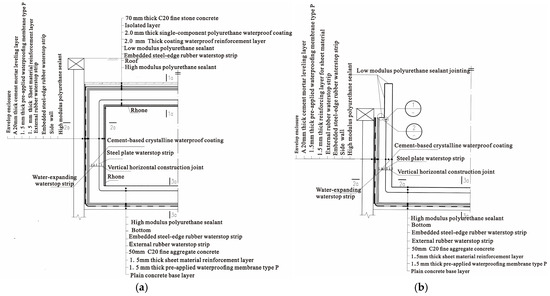
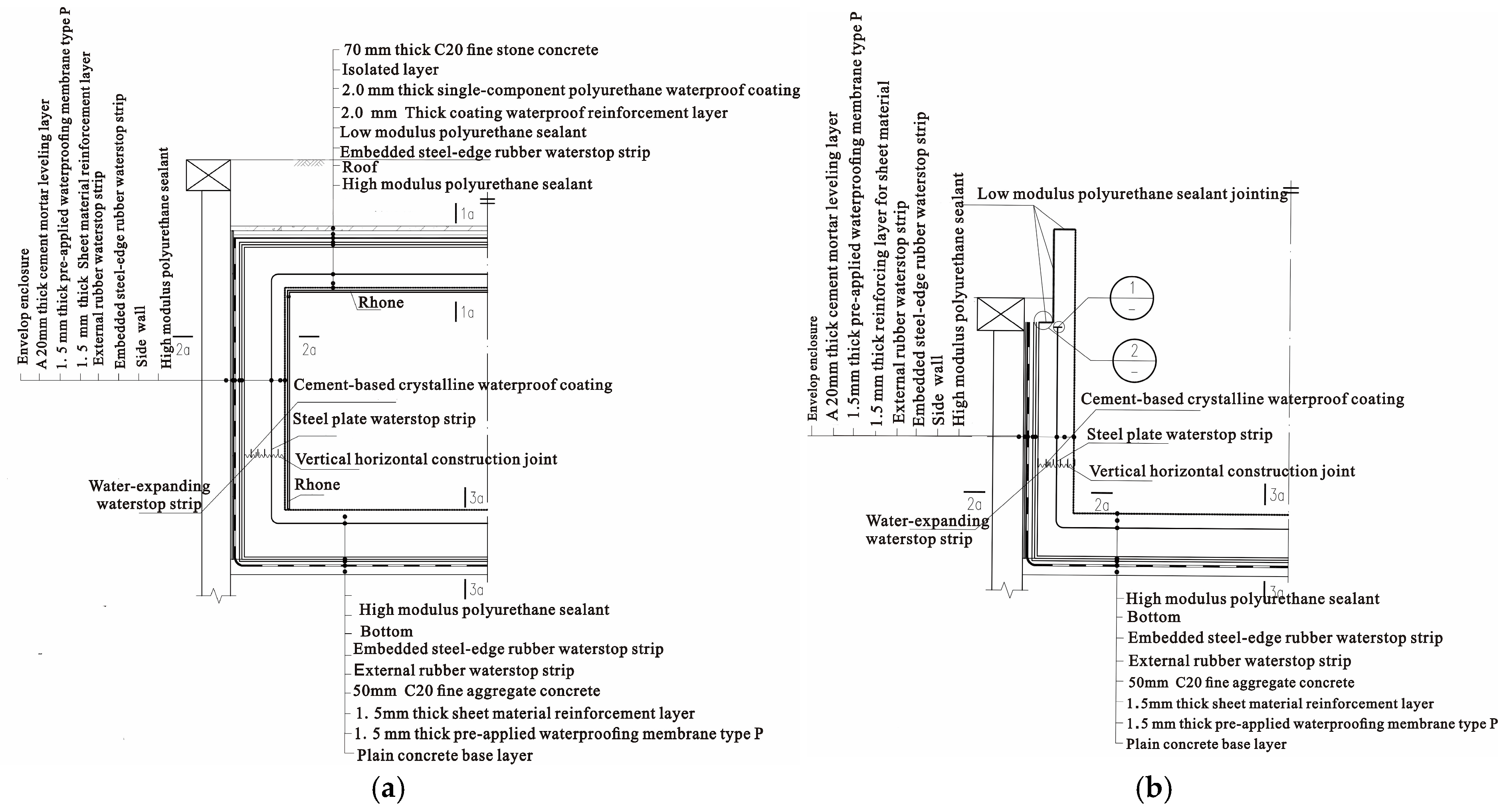
When waterproofing the joint structure, we employed the following materials and measures to meet the waterproofing requirements. We used a water-expanding waterstop, which expands when exposed to water and actively seals gaps. The tensile strength of the waterstop exceeds 0.5 MPa, and the water resistance pressure reaches 1.5 MPa. The cement-based crystalline waterproof coating penetrates the structure and forms crystalline bodies that fill the capillary pores. The 28-day bonding strength of this coating is significantly greater than 1.0 MPa, and its compressive strength is greater than 15 MPa. The embedded rubber waterstop can physically block the water infiltration path, with a tensile strength greater than 12 MPa. This waterproofing method significantly reduces the cost of subsequent water leakage repairs and fully meets the waterproof performance requirements of 0.8 MPa for the operation period of this underground passage. The waterproof structure is shown in Figure 5. The construction details of each part of the joint are given below.
Figure 5.
Waterproofing of the deformation joints. (a) The hidden section. (b) The open section.
- The main joint sealing of the embedded section channel is depicted in Figure 5a. The main waterproofing parts consist of external embedded waterstop strips, mid-buried steel-edge rubber waterstop strips, and a high-modulus polyurethane sealant. The center lines of the external embedded waterstop strips and mid-buried steel-edge rubber waterstop strips should coincide with the structural joints, and the sealant is used to seal. For longitudinal horizontal construction joints, a steel-edge rubber waterstop strip is installed. Additionally, the surface of the construction joint is coated with cement-based crystalline waterproof coating, and the joint-filling thickness is 30 mm. For transverse vertical construction joints, a mid-buried steel-edge rubber waterstop strip is pre-buried, and the construction joint is coated with cement-based crystalline waterproof coating.
- The joint waterproofing measures used for the open section are similar to those used for the embedded section. The difference lies in the fact that the mid-buried steel-edge rubber waterstop strip used for the deformation joint below the top of the side wall is sealed with an expansion rubber putty block, and the external embedded rubber waterstop strip is sealed at the top of the side wall with sealant for joint sealing. The inner side of the deformation joint is sealed with sealant, as shown in Figure 5b.
4.3. The Impact of Underground Passage Construction
4.3.1. Simulation Model
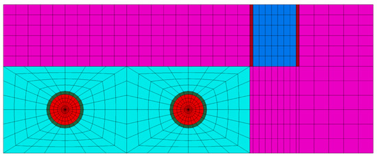
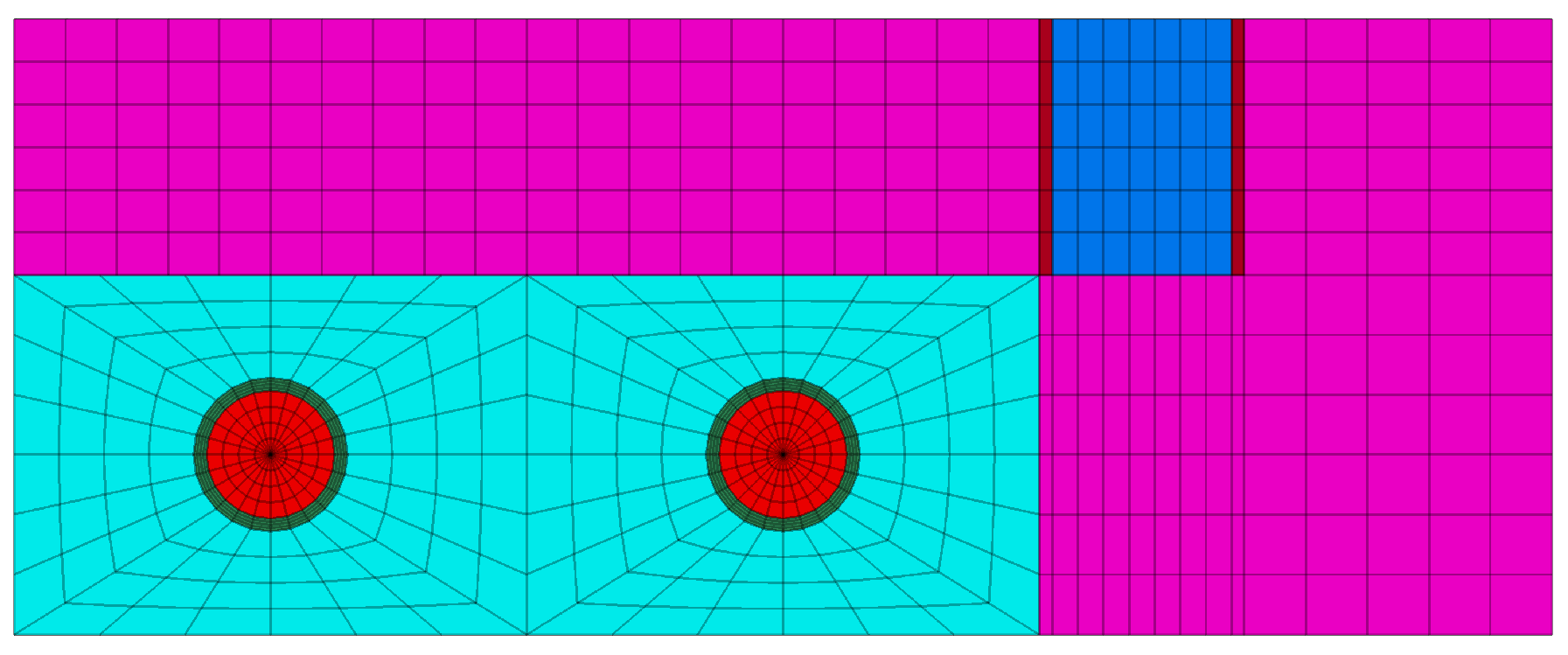
We established a calculation model using finite-element numerical simulation software [27,28], taking the construction of the main channel as an example. The main focus of this research was the impact of the construction of the main channel on the subway line. The model’s dimensions were 60 × 1 × 24 m, and the depth in modeling was 2 to 4 times the excavation depth [29], as shown in Figure 6. Fix the X-direction displacements of all nodes on the fixed boundary surfaces X = −30 and X = 30. Fix the Y-direction displacements of all nodes on the fixed boundary surfaces X = 0 and X = 1; Fix the displacement of the bottom edge surface in the Z direction. To excavate the main channel, we adopted OSM technology for construction, and the sliding retaining arm on the side wall of the channel was replaced by a traditional retaining wall, which assumed the former’s supporting role. All this was simulated using solid elements. The excavation depth of the main channel was 7 m. The road of Metro Line 3 lies below the main channel. A tunnel model was established, with a tunnel diameter of 6 m, for simulation. The soil layer parameters are given in Table 3. In the numerical simulation, we used the Mohr–Coulomb constitutive model for calculation.
Figure 6.
Diagram of the numerical model.
Table 3.
Soil layer parameters.
4.3.2. Results
- 1
- The effects of the excavation of the main channel on the deformation of the ground and the side walls
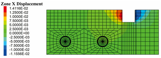
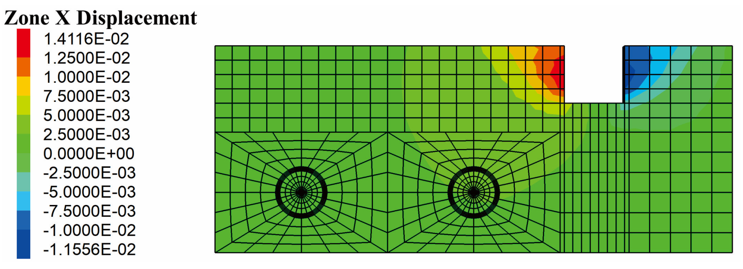
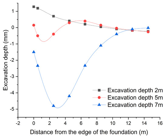
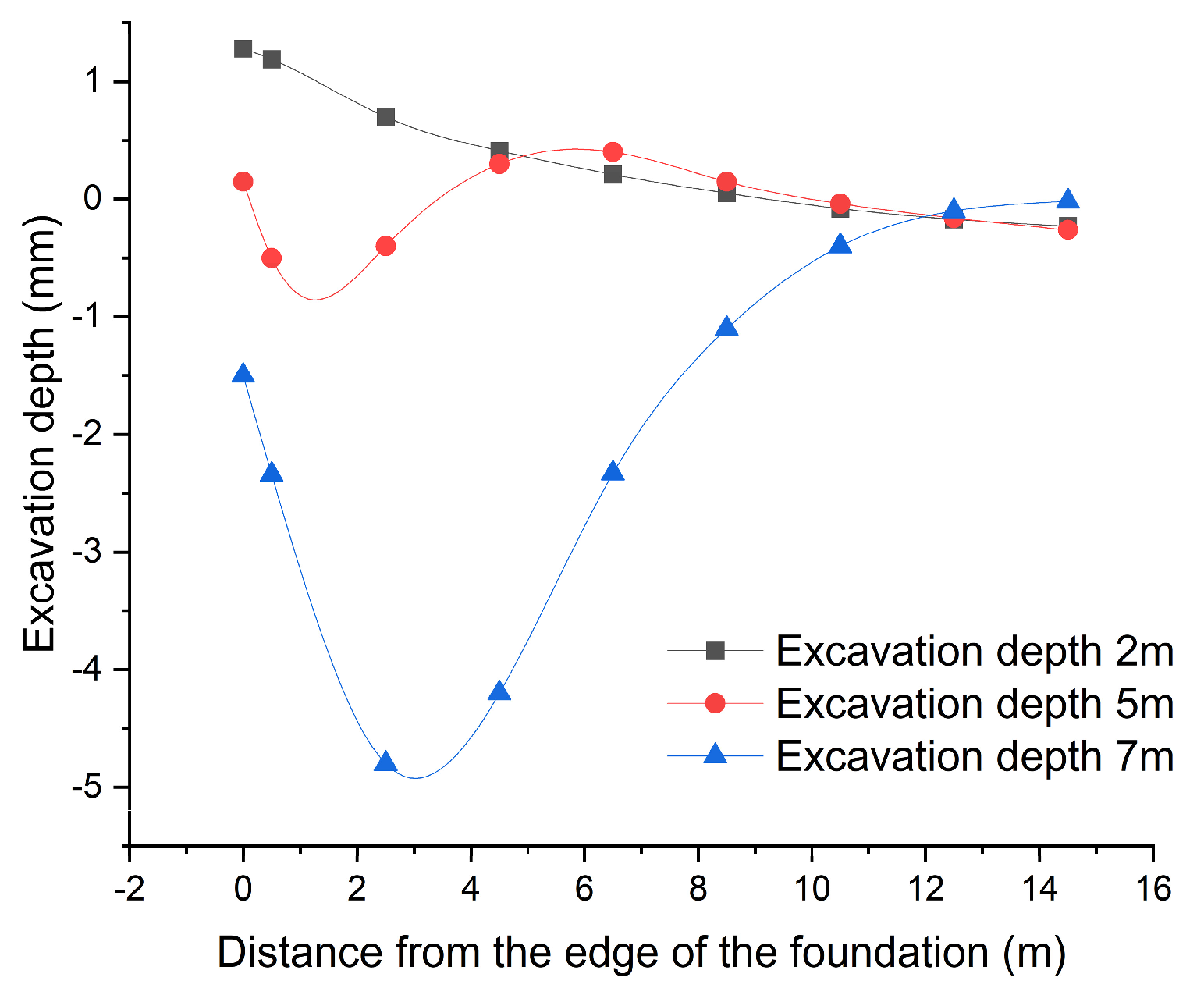
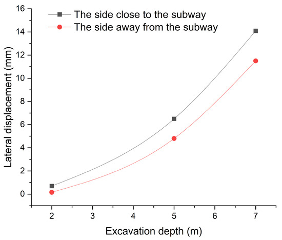
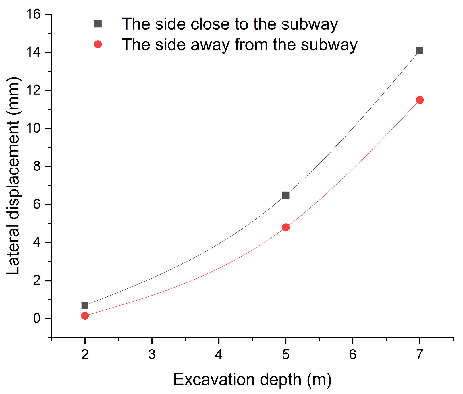
Figure 7 presents cloud images showing the impact on the side walls of the channel and the subway track when 7 m of the main channel had been excavated. The figure reveals that during the construction of the main channel, the sides of the channel moved inward towards the interior of the channel, and the degree of lateral displacement on the side closer to the subway was greater. Figure 8 shows that the ground near the channel area bulged, and the degree of bulging gradually increased with the increase in excavation depth. At the same excavation depth, as the distance from the channel increased, ground subsidence reached a maximum value and then gradually decreased, and the influence gradually disappeared at a position far from the channel. Overall, its behavior presented a trough shape. With the increase in excavation depth, the maximum value of ground subsidence increased too. Figure 9 reveals that the lateral displacement of the channel’s side walls gradually increased with the increase in excavation depth. On the side closer to the subway track, the degree of lateral displacement was greater than that on the side farther from the subway track.
Figure 7.
Schematic of lateral displacement during the construction of the main channel.
Figure 8.
Impact of the depth of excavation during the construction of the main channel on ground subsidence.
Figure 9.
Channel excavation depth and maximum lateral displacement of the channel’s side walls.
- 2
- The effects of the excavation of the main tunnel on the deformation of nearby subway lanes
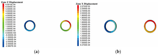
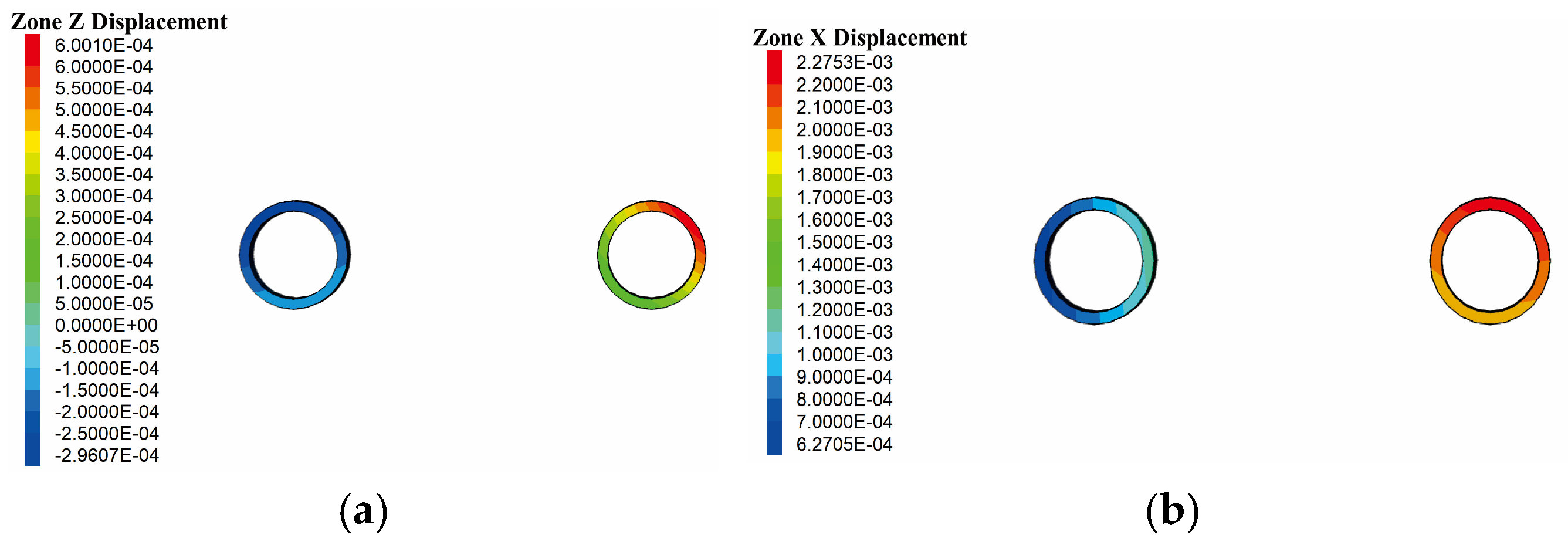
Figure 10 indicates that by the time 7 m of the channel had been excavated, the subway lane near the excavation site had undergone relatively large vertical and horizontal displacement. The maximum vertical displacement on the side of the main channel undergoing excavation was 0.6 mm, and the horizontal displacement was 2.23 mm. In contrast, on the side far from the construction of the channel, the vertical displacement deformation was 0.3 mm, which can be disregarded, and the lateral displacement was 0.63 mm. These results indicate that the construction of the channel had a certain impact on the subway lane, but the degree of influence was relatively small and falls within the controllable range.
Figure 10.
The influence of channel construction on the deformation of the subway track. (a) The vertical deformation. (b) The lateral deformation.
- 3
- Monitoring subway track deformation during the construction of the main passage
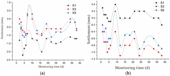
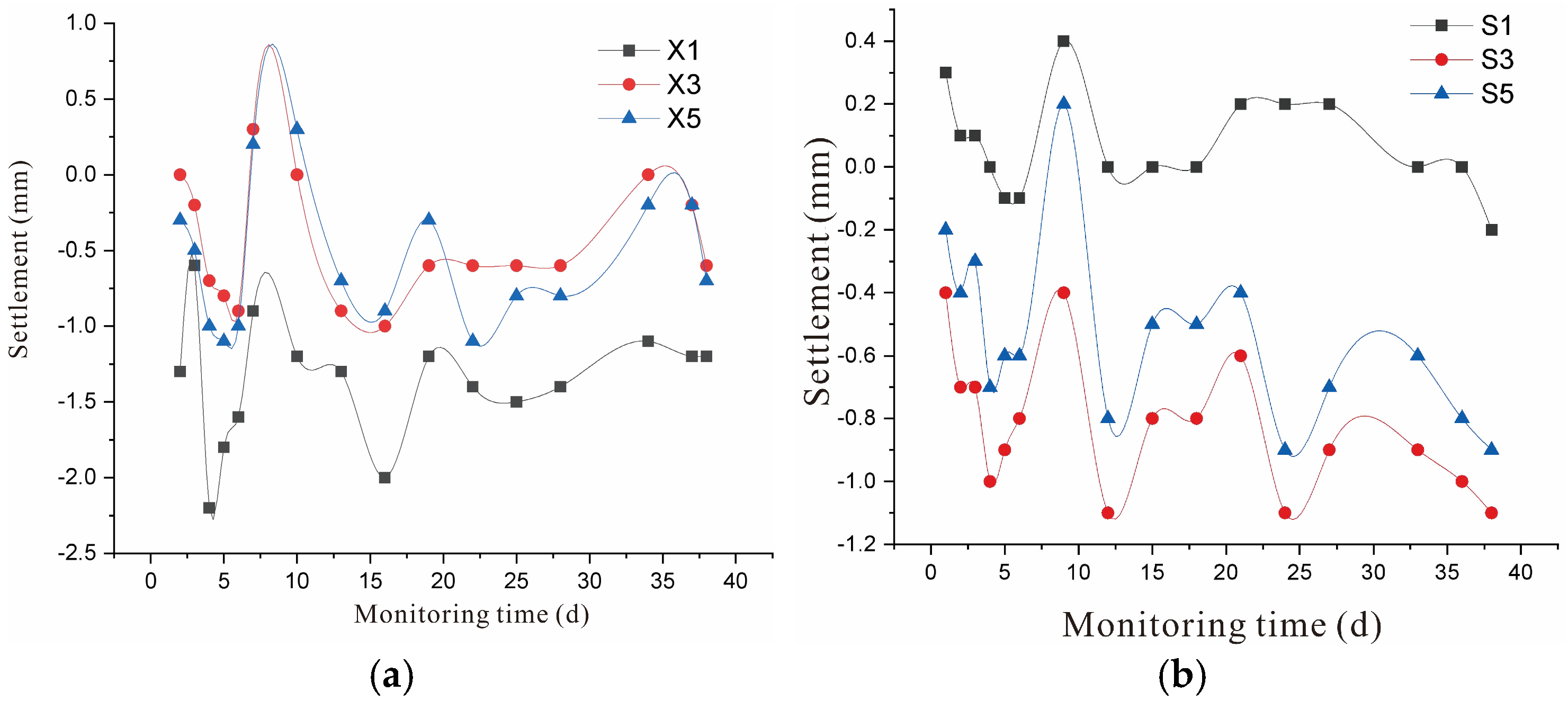
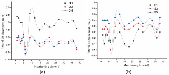
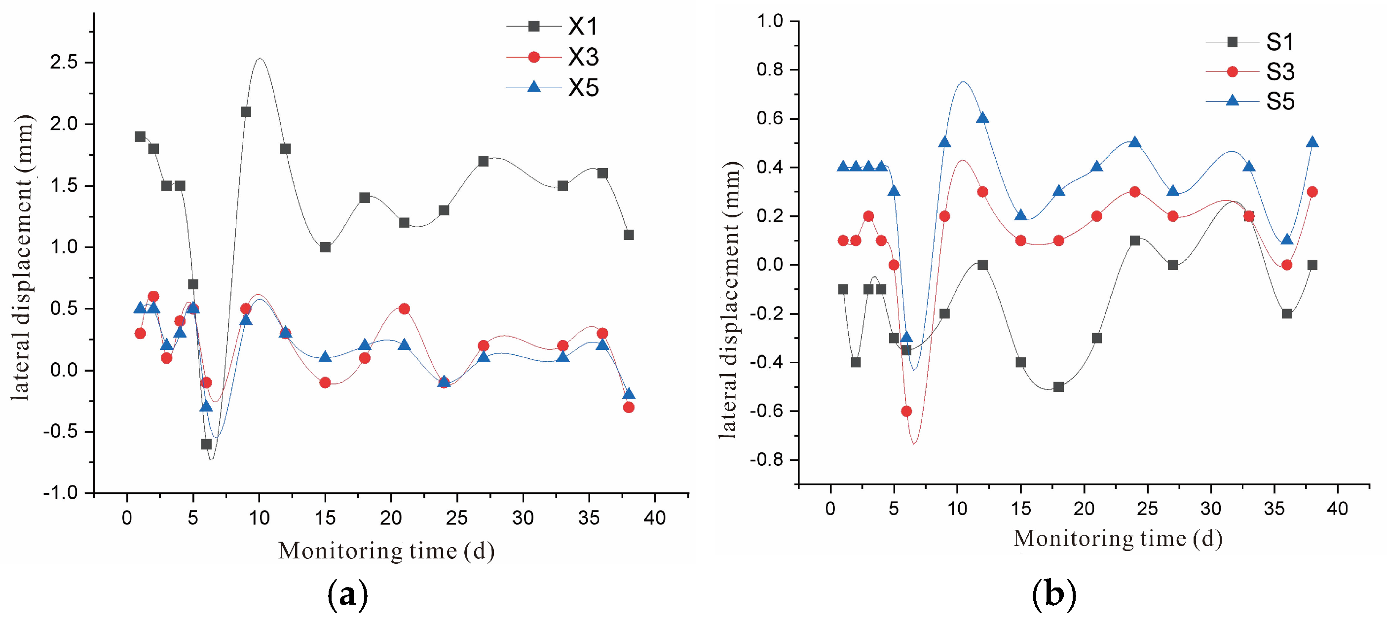
The data collected during the continuous monitoring of the subway track over the 38-day construction period were organized into Figure 11 and Figure 12. In Figure 11a, we can see that the maximum settlement of track-bed monitoring point X1 on the side close to the main passage was 2.2 mm, and monitoring points X3 and X5 show a similar pattern. On the side far from the main passage, the maximum settlement of track-bed monitoring point S3 was 1.1 mm, surpassing the values for monitoring points S5 and S1, as shown in Figure 11b. The maximum lateral displacement of track-bed monitoring point X1 on the side close to the main passage was 2.1 mm. According to the trend line in the figure, the maximum displacement should be 2.6 mm in Figure 12a; monitoring points X3 and X5 show a similar displacement pattern. On the side far from the main passage, the maximum lateral displacement of track-bed monitoring point S3 towards the outer side of the channel wall was 0.6 mm, and the maximum lateral displacement of monitoring point S5 towards the inner side of the channel wall was also 0.6 mm, as shown in Figure 12b. Monitoring point S1 had the smallest lateral displacement. During the construction of the channel, the values of all monitoring indicators were below the allowable values, as shown in Table 4. However, we can also observe that the impact of underground passage construction on the subway lanes has a certain influence, but all are below the standard, this also proves that the OSM method is feasible in the construction of underground passages. By comparing the monitoring data with the numerical simulation results, we can observe that the deformation of the subway track is close to the numerical simulation outcomes, and the impact of the underground passage on the subway track is far less than the deformation control value, evidencing the superiority of the OSM.
Figure 11.
Monitoring maps of metro track settlement during channel construction. (a) The ballast bed on the side close to the main passage. (b) The ballast bed on the side far from the main passage.
Figure 12.
Monitoring map of the lateral displacement of the metro lane during construction. (a) The ballast bed on the side close to the main passage. (b) The ballast bed on the side far from the main passage.
Table 4.
Control values for structural deformation of underground lines in urban rail transit.
- 4
- Ground subsidence and bridge pier subsidence during main-passage construction
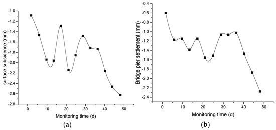
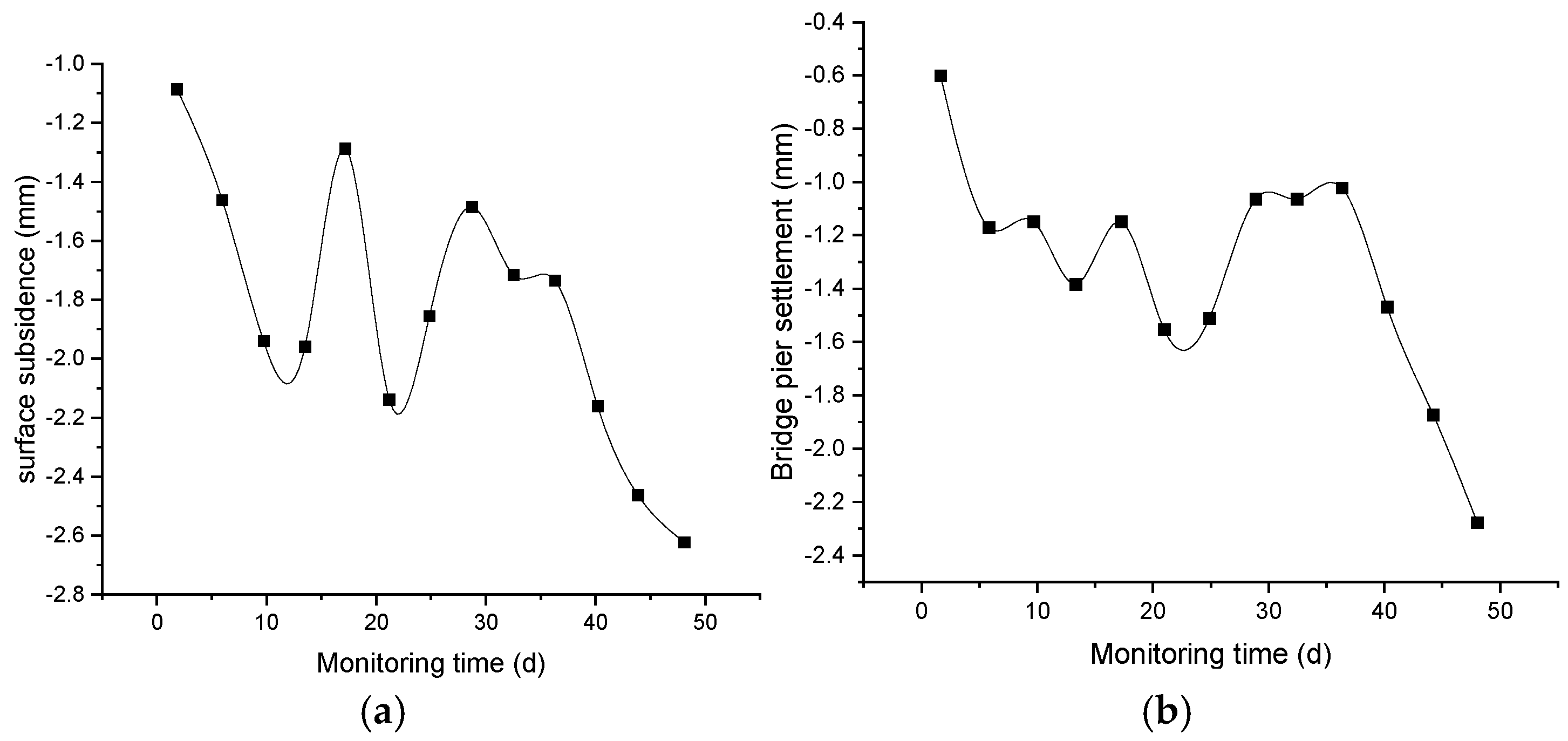
A construction impact analysis was conducted on one ground monitoring point and one bridge pile monitoring point of the main channel. As shown in Figure 13a, the construction of the main channel leads to an increasing trend in ground subsidence deformation after the oscillation. The maximum value reaches −2.5 mm, which might be due to the gradually increasing load-bearing capacity caused by the deepening of the channel excavation. Figure 13b shows that the settlement of the bridge piers also exhibits a similar deformation trend. As shown in Figure 13, rapid subsidence occurred at the end of the monitoring period, with the maximum subsidence reaching −2.3 mm. This might be due to the fact that after the construction excavation reached the bottom of the main passage, the traffic load increased as traffic resumed during the day.
Figure 13.
Monitoring map of the ground subsidence and bridge pier subsidence during construction. (a) The ground subsidence. (b) The bridge pier subsidence.
4.4. Evaluation of Application Effectiveness
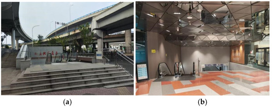
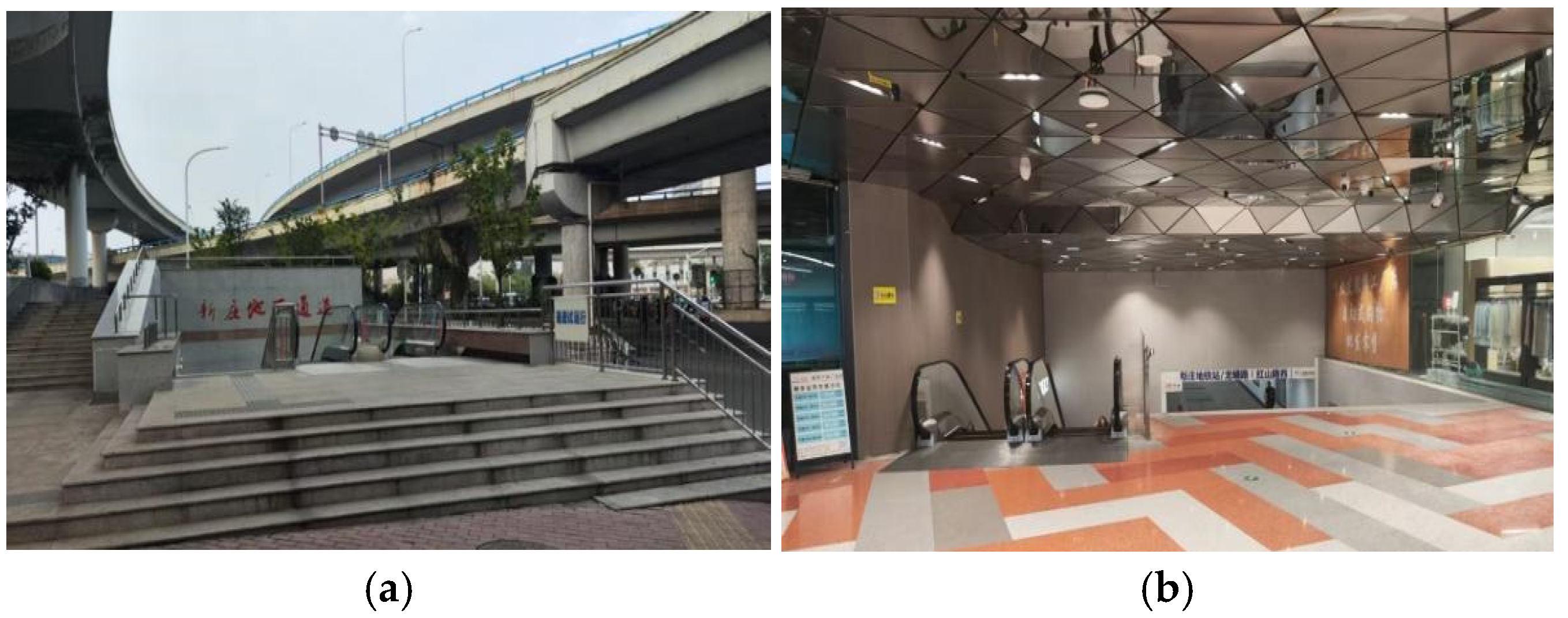
Through the monitoring of the metro track and surrounding bridge piles during the construction process, the OSM successfully controlled ground surface settlement within 5 mm, which is significantly better than the control standard of the conventional shield method, with a two-thirds reduction. At the same time, the deformation of the metro Line 3 track is also much smaller than the allowable deformation control value of the metro, shortening the construction period and improving the engineering benefits. A series of tests have demonstrated the technical advantages of this method in maintaining the stability of the stratum under complex geological conditions. A diagram of the effects is shown in Figure 14.
Figure 14.
Completion of the underground passage. (a) One side of the underground passage. (b) Another side of the underground passage.
5. Conclusions
The OSM is suitable for construction in narrow spaces with a small overburden and in complex surrounding environments. We analyzed the construction difficulties posed by urban underground passages, the key procedures of open-shield excavation, and the key methods and technologies for installing prefabricated structures. We then selected the construction of the Nanjing Xinzhuang underground passage as a demonstration project by simulating and monitoring the influence of passage excavation on the surrounding ground and metro tracks. The main conclusions are as follows:
- The OSM can achieve direct excavation without additional support structures under ultra-shallow-burial conditions. The OSM is a sliding soil retaining arm–articulated thrusting integrated system featuring prefabricated-component installation and synchronous grouting. It is highly adaptable to geological conditions, enabling construction in narrow spaces with minimal disturbance of the surrounding environment.
- The influence of the construction of the main passage on the surrounding ground exhibited a trough shape, with uplift near the passage wall, maximum settlement in the middle, and the greatest impact on the metro track occurring on the side of the passage, with a settlement value of 2.2 mm and a lateral displacement of 2.1 mm. The extent of deformation on the far side was relatively small, with all values being below the allowable values.
- The OSM is highly suitable for urban areas with shallow soil cover and stringent pipeline protection, offering minimal traffic impacts, low noise, and a small footprint. However, it performs poorly on hard rock or coarse gravel strata. Despite being an innovative method with few cases and limited experience, future improvements in construction efficiency, particularly regarding hard rock, are expected.
- This set of methods provides a certain practical engineering reference basis for urban interval underground passages and tunnel and pipeline construction in similar construction environments, and it has certain engineering innovation significance for underground engineering construction.
Author Contributions
Conceptualization, J.X. and L.W.; methodology, J.Y. and C.Y.; validation, J.X. and L.Y.; formal analysis, X.C.; investigation, S.C. and L.Y.; data curation, J.Y. and X.C.; writing—original draft preparation, J.X. and J.Y.; writing—review and editing, L.W. and X.C.; supervision, C.Y. All authors have read and agreed to the published version of the manuscript.
Funding
This research received no external funding.
Data Availability Statement
The authors declare that the data supporting the findings of this study are available within the paper.
Conflicts of Interest
Authors Jianming Xu, Jiang Yu, Xueqing Chen, Lu Yan, Shunqi Chen are employed by the Shanghai Tunnel Engineering Co., Ltd., Municipal Public Engineering Design and Research Institute. The remaining authors declare that the research was conducted in the absence of any commercial or financial relationships that could be construed as a potential conflict of interest.
References
- Qin, K.; Liang, G.; Wang, B.; Li, Y. Deformation and numerical analysis of deep foundation pit under water-rich ground fissure. Adv. Civ. Eng. 2025, 2025, 9910145. [Google Scholar] [CrossRef] [Scilit]
- Jiang, B.; Wei, H.; Wei, D.; Ma, Z.; Wang, F. Interlayer soil settlement prediction in the construction of under-crossing existing structures based on multi-parameter time series model. Undergr. Space 2025, 24, 335–351. [Google Scholar] [CrossRef] [Scilit]
- Ge, C.; Yang, M.; Li, P.; Zhang, M. Influence of deep foundation pit excavation on surrounding environment: A case study in Nanjing, China. Acta Geophys. 2025, 73, 495–516. [Google Scholar] [CrossRef] [Scilit]
- Zhao, J.; Wang, X.; Tan, Z.; Zhang, X.; Xiao, X. Excavation optimization for asymmetrical deep foundation pits adjacent to subway stations: Deformation control and safety enhancement. Int. J. Geomech. 2025, 25, 05025010. [Google Scholar] [CrossRef] [Scilit]
- Sun, Y.; Li, Z. Study on design and deformation law of pile-anchor support system in deep foundation pit. Sustainability 2022, 14, 12190. [Google Scholar] [CrossRef] [Scilit]
- Zhang, D. Influences of deep foundation pit excavation on the stability of adjacent ancient buildings. Buildings 2023, 13, 2004. [Google Scholar] [CrossRef] [Scilit]
- Liu, J.; Xue, B.; Wang, H.; Zhang, X.; Zhang, Y. Numerical study on the behavior of an existing tunnel during excavating adjacent deep foundation pit. Sustainability 2023, 15, 9740. [Google Scholar] [CrossRef] [Scilit]
- Jiang, S.; Chen, W.; Ma, R.; Lv, X.; Sun, F.; Ren, Z. Dynamic response of adjacent tunnels to deep foundation pit excavation: A numerical and monitoring data-driven case study. Appl. Sci. 2025, 15, 10570. [Google Scholar] [CrossRef] [Scilit]
- Lei, H.; Zhan, B.; Feng, S.; Amin, M. Influence of foundation pit groups’ excavation on the deformation characteristics of adjacent railway subgrade and protection measures. Geotech. Geol. Eng. 2023, 41, 3877–3895. [Google Scholar] [CrossRef] [Scilit]
- Yang, K.; Jiang, M.; Chi, M.; Feng, G. Numerical analysis of diaphragm wall deformation and surface settlement caused by dewatering and excavation at center and end positions in a subway foundation pit. Buildings 2025, 15, 2796. [Google Scholar] [CrossRef] [Scilit]
- Yin, H.; He, C.; Shan, H. Intelligent settlement forecasting of surrounding buildings during deep foundation pit excavation using GWO-VMD-LSTM. Buildings 2025, 15, 3688. [Google Scholar] [CrossRef] [Scilit]
- Xu, L.; Li, W.; Liu, L.; Wu, F.; Fan, Z.; Chen, R. Deformation analysis of a deep excavation with a servo control system adjacent to an existing foundation pit: A case study in Shenzhen. Tunn. Undergr. Space Technol. 2026, 170, 107374. [Google Scholar] [CrossRef] [Scilit]
- Sun, W.; Fan, D.; Hu, W.; Wang, J. Research on the protection measures of the metro tunnels under the newunderpass. J. Railw. Eng. Soc. 2019, 36, 86–91. [Google Scholar]
- Chen, S.; Cao, C.; Liao, Z. The influence of deep excavation on the deformation of surrounding rectangular underground tunnel based on different supporting forms. J. Transp. Sci. Eng. 2018, 34, 43–52. [Google Scholar]
- Li, C. Analysis on Influence of Lanzhou Metro Line No.1 undercrossing an existing underground passage. Railw. Eng. 2017, 57, 53–56. [Google Scholar]
- Jin, Z.; Qi, T.; Liang, X. Evaluation of the structural and waterproof performance of a precast and assembly underpass under long-term surface dynamic loads. Tunn. Undergr. Space Technol. 2021, 115, 104047. [Google Scholar] [CrossRef] [Scilit]
- Li, H.; Wu, H.; Cao, H.; Chen, R. Long-term waterproof performance of EPDM sealing gaskets considering aging-induced stress relaxation. Tunn. Undergr. Space Technol. 2026, 168, 107117. [Google Scholar] [CrossRef] [Scilit]
- Wu, R.; Wu, H.; Li, H.; Yang, X.; Feng, D.; Cao, H.; Chen, R. Prediction on the waterproof performance of EPDM gaskets in shield tunnels considering the stress state of compression and tension. Tunn. Undergr. Space Technol. 2026, 167, 107090. [Google Scholar] [CrossRef] [Scilit]
- Yu, Y.; Zhang, G.; Zhang, W.; Liu, Y.; Zhou, X. Numerical and experimental investigation on waterproof performance of novel sealing gasket for bolt holes in shield tunnel segments. Processes 2025, 13, 3337. [Google Scholar] [CrossRef] [Scilit]
- Huang, F.; Li, S.; Duan, W.; Zhou, X.; Xu, H.; Zhang, X. Study on long-term waterproof performance and failure mechanism of shield tunnel gasket under compression. Eng. Fail. Anal. 2025, 167, 109050. [Google Scholar] [CrossRef] [Scilit]
- Hu, Z.; Sun, Y.; Jiang, L.; Mao, H.; Xu, Y.; Luo, Y. Waterproof performance and failure mechanism of GINA gasket subject to diverse joint deformations: A case study of the Yuliangzhou immersed tunnel. Case Stud. Constr. Mater. 2025, 22, e4449. [Google Scholar] [CrossRef] [Scilit]
- Liu, Y.; Huang, L.; Tang, X.; Xue, Y.; Ke, W.; Luo, Y.; Guan, L. Analysis of influence of cut-and-cover method on retaining structures and differential settlement in subway foundation pit construction. Appl. Sci. 2025, 15, 7520. [Google Scholar] [CrossRef] [Scilit]
- Che, Y.; Chi, E. Safety assessment of the cover-and-cut method under blasting vibration induced by tunnel excavation. Appl. Sci. 2025, 15, 260. [Google Scholar] [CrossRef] [Scilit]
- Fang, Q.; Zhang, D.; Wong, L.N.Y. Shallow tunnelling method (STM) for subway station construction in soft ground. Tunn. Undergr. Space Technol. 2012, 29, 10–30. [Google Scholar] [CrossRef] [Scilit]
- Niu, Y.; Xie, Y.; Zhang, H.; Yue, X.; Han, Y.; Hu, Z. Study on deformation characteristics of segment joints of the immersed tunnel in Hong Kong-Zhuhai-Macau bridge. Adv. Mater. Sci. Eng. 2022, 2022, 7152132. [Google Scholar] [CrossRef] [Scilit]
- Wang, Z.; Shen, S.; Zhou, A.; Lyu, H. Investigation of time-dependent characteristics of EPDM rubber gasket used for shield tunnels. J. Mater. Civ. Eng. 2021, 33, 04021251. [Google Scholar] [CrossRef] [Scilit]
- Shi, J.; Xu, Y.; Li, H.; Yan, C.; Hou, J.; Yu, L.; Zhao, H.; Cui, W.; Xu, C. Study on the impact of deep and large shaped foundation pit construction on adjacent grand bridge and deformation control in diffuse beach area of Yangtze River. Geol. Rev. 2024, 70, 1443–1454. [Google Scholar]
- Cheng, H. Stability analysis of foundation pit excavation based on finite difference FLAC3D. J. Railw. Eng. Soc. 2023, 40, 32–38, 45. [Google Scholar]
- Feng, T.; Wang, Z.; Zhang, J.; Peng, P.; Sun, J.; Wang, W.; Li, M. A numerical simulation study on the influence of foundation pit excavation unloading on lateral tunnel: A metro station foundation pit excavation in Nanjing as an example. J. East China Univ. Technol. (Nat. Sci.) 2024, 47, 482–494. [Google Scholar]

Disclaimer/Publisher’s Note: The statements, opinions and data contained in all publications are solely those of the individual author(s) and contributor(s) and not of MDPI and/or the editor(s). MDPI and/or the editor(s) disclaim responsibility for any injury to people or property resulting from any ideas, methods, instructions or products referred to in the content. |
© 2026 by the authors. Licensee MDPI, Basel, Switzerland. This article is an open access article distributed under the terms and conditions of the Creative Commons Attribution (CC BY) license.