


Abstract
One-way joist slab floor systems are commonly favored in modern residential building applications due to their efficiency in architectural and structural design processes. However, a significant number of such buildings experienced heavy damage or collapse mechanisms during the catastrophic earthquakes in Türkiye since they are more vulnerable due to some uncertainties in the design and construction stages. In this regard, although well-known seismic codes such as Eurocode, IBC, and ASCE do not impose additional requirements for the design of structural systems with joist slabs, the seismic codes of some Mediterranean basin countries regulate the ductility levels, use of shear walls, and member/system-based specific requirements. In the present study, the impact of shear wall quantity on the seismic behavior of reinforced concrete buildings with one-way joist slabs was investigated in five-story structural systems, which were basically similar in terms of the slab properties and layout but have different overturning moment ratios (αM = 0.75, 0.60, 0.45, 0). In this context, a total of 88 bi-directional nonlinear time history analyses were conducted on four structural systems, which were highly representative of buildings in the earthquake zones of Türkiye, under real earthquake ground motions. Hence, the seismic behavior demands—including story displacement, inter-story drift and plastic deformations, distributions of plastic hinges, and member-based performance levels—were discussed by the overturning moment ratio that is directly associated with the shear wall quantity in the system. It can be concluded that when these buildings are jointly designed with the shear walls and frames of a high ductility level—through the capacity design principles—the stipulated performance objective can be successfully achieved. While the shear wall quantities ranging from 0.45 to 0.75 did not have a significant impact on the member-based damage across all floors, the frame-only system was found to be inadequate for controlling the lateral deformations due to insufficient stiffness under design-based seismic events.
1. Introduction
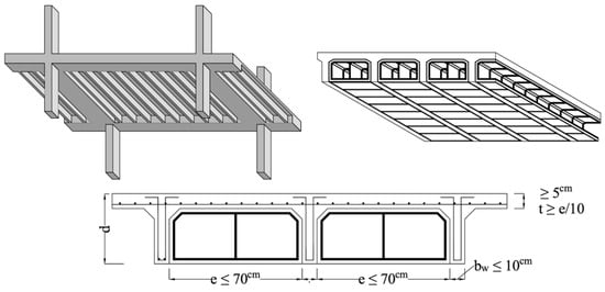
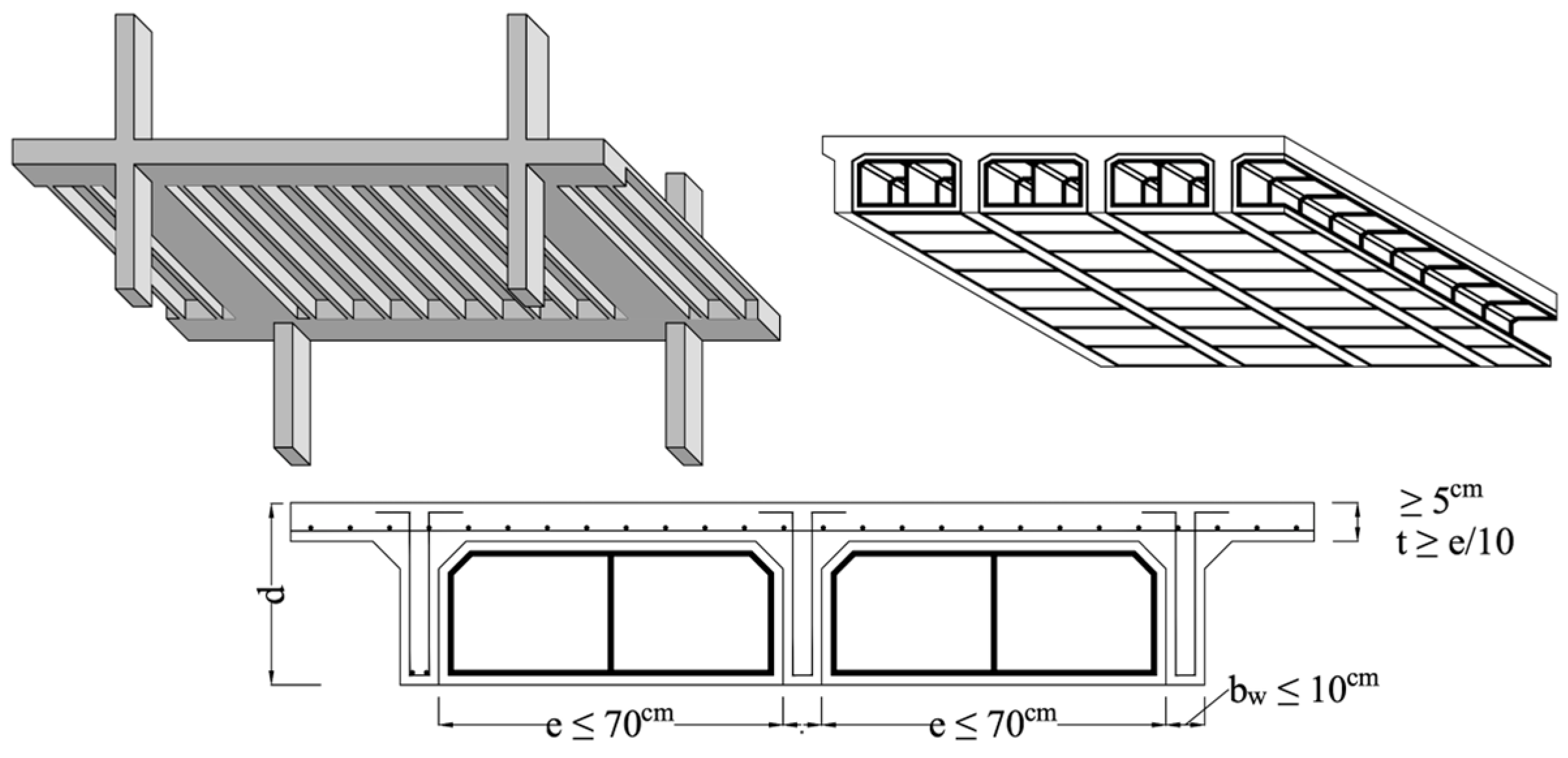
Joist slab systems are increasingly preferred in modern residential reinforced concrete (RC) building applications due to their ability to provide aesthetically pleasing, ergonomic, and functional interior volumes for architectural design demands, as well as their fast construction process. This floor system consists of thin slabs, wide beams with a width greater than their height, and equally spaced joists (ribs) in one or two directions between these beams (shown in Figure 1). The slab between the joists is cast directly atop the blocks. The heights of the wide and joist beams are chosen the same to achieve a flat slab appearance inside the apartments, and the voids are filled with materials such as hollow bricks, lightweight gas concrete, or Styrofoam to enhance thermal and acoustic insulations. This particular one-way joist slab system is called “asmolen” in Turkish, with a typical slab thickness of 32 cm (comprising 25 cm block and 7 cm slab) in construction practice.
Figure 1.
A typical one-way joist (asmolen) slab system and its dimensions.
In RC structural systems featuring joist slabs, some uncertainties—such as story drift and stability problems that may arise due to the relatively limited strength and stiffness compared to conventional deep-beam systems, as well as increasing inertia forces and P-Δ effects caused by excessive story weight, and reinforcement forces to be transferred in the beam–column joint panel—come to the forefront in seismic behavior. In this sense, some seismic codes impose specific requirements, such as the compulsory selection of low or limited ductility levels, the use of a particular amount of shear walls, and limitations on the structural behavior factor, to have a safe side against the drawbacks and uncertainties in the structural systems, unlike the deep-beam systems.
The analytical studies on the existing RC buildings with either unfilled (bare) or filled (asmolen) one-way joist slabs showed that they did not meet the stipulated performance objectives [1,2,3]. In contrast, the buildings designed in accordance with the modern seismic codes where the capacity design principles were applied and where the columns had sufficient lateral strength and stiffness exhibited a structural behavior close to that of the deep-beam system [4,5,6].
After the devastating and deadly earthquakes in Türkiye (Adana-Ceyhan 1998, Marmara 1999, Van 2011, Kahramanmaraş 2023), a large number of buildings with one-way joist slabs experienced heavy damage or collapse mechanisms in different modes. The main causes of partial/total collapses for such buildings in the earthquake-affected cities may be summarized under the following headings: insufficient lateral and rotational column stiffnesses; excessive deformation demands on ground story columns; lack of internal forces transfer from the wide beam to the column; and low material quality and construction deficiencies [1,7,8,9,10,11,12,13,14].
Although well-known seismic design codes and standards such as Eurocode-8 [15], UBC [16], IBC [17], NZS 3101 [18], and ASCE 41-17 [19] do not provide specific guidance regarding the ductility levels and/or system configurations for the design of RC buildings with joist slabs, the seismic codes of Mediterranean basin countries such as Türkiye, Italy, Spain, and Greece [20,21,22,23] regulate the ductility level of lateral force-resisting systems, the amount of shear walls, and member/system-based particular requirements [4].
Karaaslan [24] and Dönmez et al. [25] stated that the frame buildings with one-way joist slabs designed in accordance with the current and previous Turkish Seismic Codes (TEC-2007 and TEC-2018) [20,26] are more vulnerable than those of the deep-beam systems due to the reduced lateral stiffness and, consequently, the large displacement and drift demands under seismic loads. Accordingly, they recommended the construction of such structural systems with shear walls. However, Lalaj et al. [6] reported that the design requirements concerning one-way joist slab systems in TSC-2018 result in overly conservative drift demands. In Domínguez et al. [3], the seismic performances of RC buildings with wide beams featuring one-way joist slabs under the 2011 Spain–Lorca earthquake demonstrated that while three- and six-story buildings designed without any seismic consideration collapsed in one or both directions with the weak-column–strong-beam mechanisms, even with the cooperation of infill walls, the buildings with seismic provisions resisted the seismic loads with no or moderate damage in the beams and columns. Based on the studies conducted by Gómez-Martinez et al. [4,5] on a total of 72 buildings, such structural systems with wide beams showed at least as much ductile behavior as the deep-beam systems. The authors concluded that the wide-beam systems can be designed at high ductility levels and have no need for a reduction in the structural behavior factor. Vielma et al. [27] concluded that the most appropriate solution to improve the seismic behavior of waffle slab buildings was to increase the depth of the ribs. The material properties and confinement did not have a significant influence on the overall building performance.
In the recent literature studies, the significance of incorporating shear walls in the structural systems with wide beams was discussed in a numerical manner to overcome potential strength, stiffness, and deformation shortcomings under seismic loads. Burak and Çömlekoğlu [28] recommended a minimum shear wall ratio of 1.0%—indicating the percentage of the total shear wall area to the floor area—for wide-beam buildings. It was noted that exceeding this ratio of 1.5% did not have a positive influence on the seismic performance of these structures since most of the lateral seismic loads were effectively resisted by the shear walls. Günel [29] similarly emphasized that an area-based ratio of 1.0% for shear walls incorporating compression and tension boundary zones effectively limited the story drifts, and the vertical structural members behaved as almost linear–elastic with increasing shear wall ratios despite the beams not being affected by the increases. However, Akyıldız and Girgin [2] reported substantial plastic deformations in the columns and collapse damage levels in the wide beams of an eight-story building with one-way joist slabs. Turker and Gungor [30] found that while a four-story frame-only building with one-way joist slabs designed in accordance with TSC-2007 [26] achieved the life safety performance level, the seven-story building system failed to meet the stipulated performance. They pointed out that the target performance objective could be achieved by incorporating shear walls of 1.2%. Still, there is a lack of additional studies addressing the seismic performances of the buildings with joist slab systems fulfilling the code requirements.
Beyond traditional reinforced concrete systems, recent research has explored innovative lateral load-resisting mechanisms to enhance seismic resilience. Shahzad et al. [31] numerically investigated the seismic performance of mega-subcontrolled structural systems (MSCSS). Their study on various system configurations demonstrated the effectiveness of an optimized shear wall configuration in limiting plastic strains and residual story drifts under seismic excitation. Furthermore, Behzadinia and Erfani [32] evaluated the seismic demand on columns at the intersection of steel plate shear walls (SPSWs) with aspect ratios of 0.775, 1.0, and 1.525. Through nonlinear analyses of three- to twenty-story structures, they highlighted that while bending moments remained within capacity limits, the tensile axial forces in the columns were found to be critical and often governed the overall design process. In addition to the global configuration of lateral resistance systems, the in-plane stiffness of the floor diaphragm plays a pivotal role in the seismic response distribution. Ruggieri et al. [33] evaluated the impact of floor deformability on the seismic performance of low-rise RC buildings featuring joist slabs. They demonstrated that while the rigid diaphragm assumption may have a negligible effect on the seismic fragility of bare frame configurations, it can lead to non-conservative results in retrofitted structures.
The base shear ratio and the overturning moment ratio resisted by the shear walls under seismic loads decrease significantly as the number of stories increases, even if the shear wall area remains constant [28,29,34,35,36,37]. Thus, a fixed wall ratio of 1.0% can provide adequate resistance for a low-rise building but may fall short for mid-to-high-rise buildings. While a constant shear wall ratio of 0.85–1.0% roughly corresponds to an overturning moment ratio of 75%, these values fluctuate based on different shear wall placement as well as the building’s dynamic characteristics. Unlike the base shear ratio, which is closely tied to the cross-sectional area, the overturning moment ratio is highly sensitive to building height and wall placement. Therefore, relying on a “fixed geometric ratio” is an oversimplification that does not accurately capture the seismic demand distribution.
The present study evaluates the impact of shear wall quantity on the seismic behavior of RC buildings with one-way joist slabs and examines the corresponding design provisions in TSC-2018. In this sense, a typical five-story RC building, representative of buildings in earthquake zones of Türkiye, was considered by four structural systems that are basically similar in terms of the slab properties and layout but have different overturning moment ratios . The seismic response demands—including story displacement, inter-story drift and plastic deformation demands, distributions of plastic hinges, and member-based performance levels—were evaluated through 88 bi-directional nonlinear time history analyses conducted under the spectrum-compatible real earthquake record sets.
2. Design Provisions for Joist Slab Structural Systems in Turkish Seismic Codes
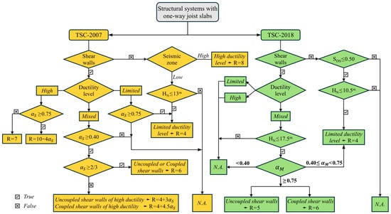
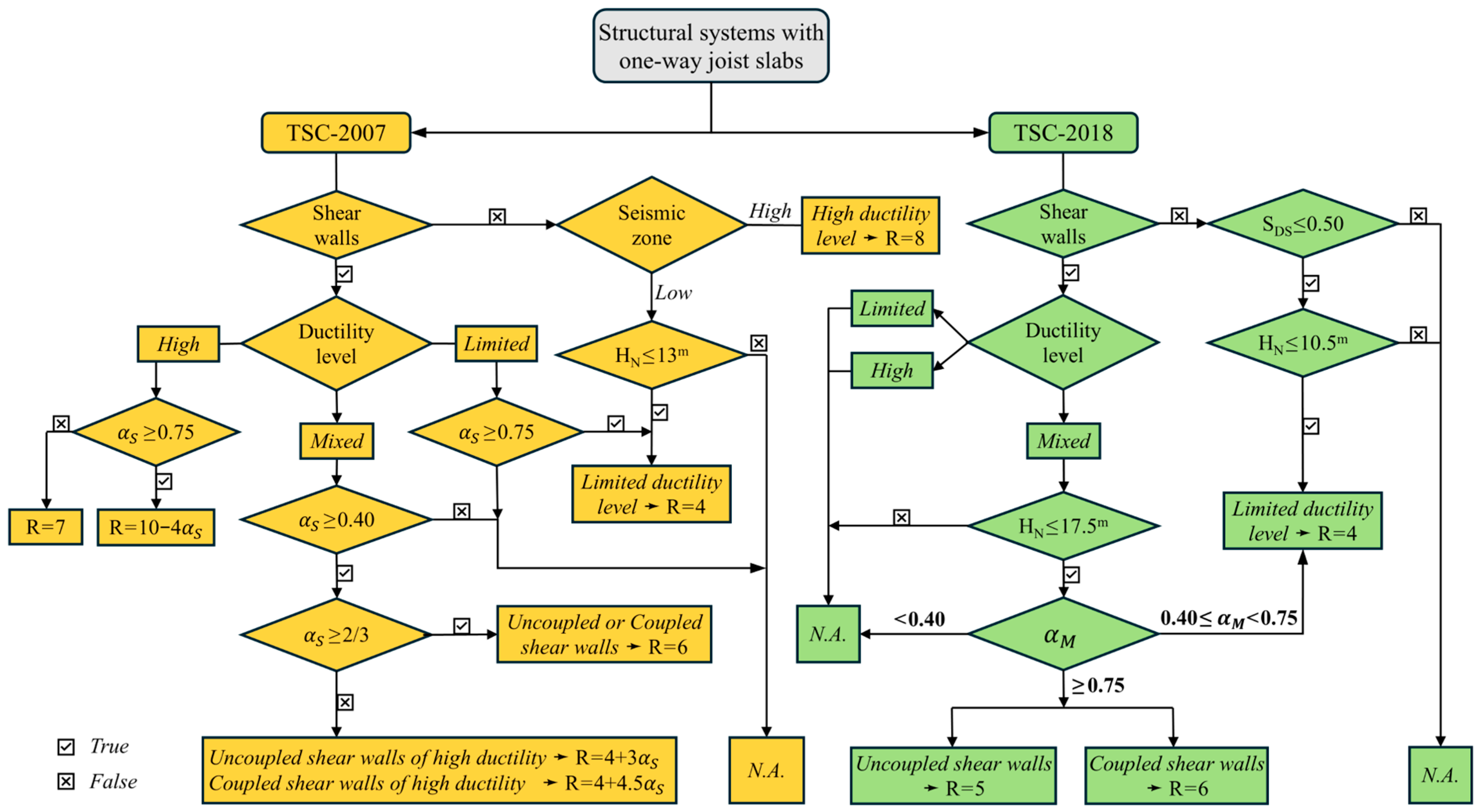
In the previous TSC-2007 [26], no design limitations were imposed for the RC buildings with bare or filled one-way joist slab floors when employing the structural system of a high ductility level. However, in the case that any of the design criteria for the high ductility class is not fulfilled, the structural system should be modeled at normal ductility (see Figure 2). Herein, the sum of shear forces developed at the bases of uncoupled structural walls under seismic loads should not exceed 75% of the total base shear for the entire building . Otherwise, the structural behavior factor (R) is reduced in the range of (see Figure 2).
Figure 2.
Summary of seismic design requirements and restrictions for RC buildings with one-way joist slabs according to TSC-2007 and TSC-2018.
The current seismic code TSC-2018 [20] has introduced stricter design-oriented criteria for buildings featuring joist slabs compared to earlier versions. In the seismic design classes SDC = 1 and 2, where the seismic effects are significant (SDS ≥ 0.50), the use of either uncoupled or coupled shear walls is not only compulsory but also the selection of the structural systems with mixed ductility level is required (Figure 2). For the SDC = 3 and 4 (SDS < 0.50), the limited ductility systems are required unless the seismic loads are not jointly resisted by the shear walls. Nevertheless, these structural systems can be designed as mixed ductility systems by forming them together with high ductility shear walls. In the mixed ductility systems for all SDC classes, as illustrated in Figure 2, the sum of overturning moments developed at the bases of the shear walls, considering both gravity and seismic loads, should exceed 75% of the total overturning moment for the entire building .
3. Numerical Analyses of RC Building Systems
3.1. Description and Numerical Modeling
For the quantitative simulations, five-story RC buildings with five equal span lengths of 500 cm in both directions were selected to investigate the impacts of shear wall quantity and ductility level on the deformation-based seismic response demands. All the structural systems are basically similar in terms of slab properties and layout but have different overturning moment ratios. The one-way joist slabs are evenly spaced in the plan and feature dimensions of 15 cm × 25 cm × 7 cm (web width × height × flange thickness). The clear spacing between the ribs is equally 70 cm and the voids are filled with hollow bricks that have a self-weight of 1.19 kN/m2. The overall height of the beam is 32 cm.
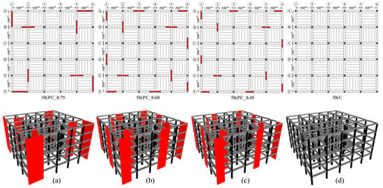
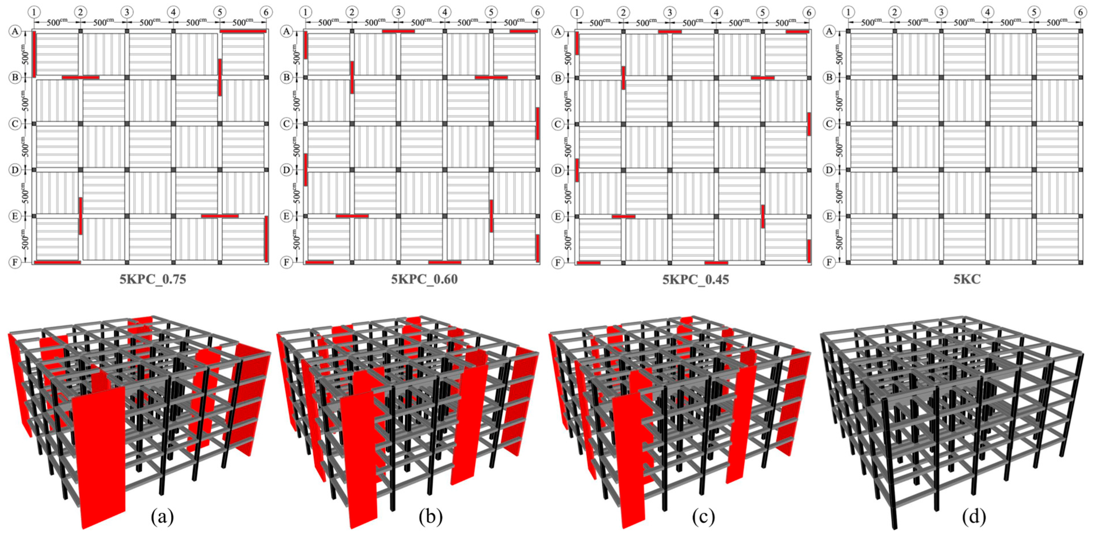
In the numerical analyses, the first structural system, referred to as “5KPC_0.75”, was designed as the mixed ductility system in accordance with TSC-2018 [20], in which the seismic loads are jointly resisted by limited ductility frames and uncoupled shear walls of high ductility levels (see Figure 3a). In this configuration, the overturning moment ratio is , and the shear wall ratio is 0.86% for each story. The second system “5KPC_0.60” comprising the shear walls and frames of high ductility levels (see Figure 3b). This design is no longer permitted in the current TSC-2018 despite the fact that the previous versions, TSC-1998 [38] and TSC-2007 [26], had allowed the use of high ductility levels for the buildings with joist slabs. For the 5KPC_0.60, the overturning moment ratio is , and the shear wall ratio is 0.96% for each story. The structural system “5KPC_0.45” is very similar to that of 5KPC_0.60, but it has an overturning moment ratio of , and the shear wall ratio is at a lower level of 0.60 (see Figure 3c). It can be noted that this configuration corresponds to the lower bound of 0.40 for highly ductile shear wall–frame systems in TSC-2018.
Figure 3.
Structural floor plans and 3D analysis models of buildings: (a) 5KPC_0.75; (b) 5KPC_0.60; (c) 5KPC_0.45; and (d) 5KC.
Lastly, the reference system “5KC” consisted of highly ductile frames only as shown in Figure 3d. This model was considered to reveal the necessity of shear walls in the joist slab structural systems subjected to seismic loads. While the previous code versions allowed for the use of high ductility frames in such buildings, the limited ductility systems can be selected in only SDC = 3 and 4 classes in accordance with TSC-2018 [20].
The general design characteristics of the buildings are given in Table 1, and floor plans and three-dimensional analysis models are presented in Figure 3a–d. More details about the design considerations for the structural systems, including cross-section dimensions, longitudinal/transverse reinforcements, and further information may be found in Kurt [39].
Table 1.
Summary of design parameters for RC buildings.
In the numerical modeling of structural systems, a full bond interaction was assumed between concrete and reinforcing steel, ensuring strain compatibility across the section. To realistically capture flexural stiffness degradation under seismic demands, effective (cracked) section stiffness values were assigned to beams, columns, and shear walls in accordance with the requirements of TBDY-2018 [20]. The uniaxial compressive stress–strain relationship provided by Mander et al. [40] was applied to both confined and unconfined concrete. It should be noted that the tensile strength of concrete was neglected. Furthermore, a simple bilinear constitutive model with kinematic hardening was used to simulate the nonlinear behavior of longitudinal reinforcement. The characteristic stress and strain values for these materials are provided in Table 1.
In the construction of elastic and inelastic components using the SAP2000 software (version 21) [41], the beams and columns were modeled with one-dimensional frame members, with zero-length plastic hinges based on the lumped plasticity concept [42]. In this approach, inelastic deformations are lumped at the end regions while the member responses in other zones are linear elastic. The inelastic behavior of the beam plastic hinges was characterized by user-defined bilinear moment–plastic rotation (M–θp) relationships, which were obtained from moment–curvature analyses conducted for each design configuration. These hinges were defined as zero-length M3 hinges and placed at the mid-point of the plastic hinge lengths at both ends of the beams. For column plastic hinges, three-dimensional yield surfaces (P–M2–M3) were prepared to account for the combined effects of axial force and biaxial bending moments. At this point, the plastic hinge length (Lp) was considered to be half of the height of the beam and column cross-sections (Lp = 0.5 h) in accordance with TSC-2018.
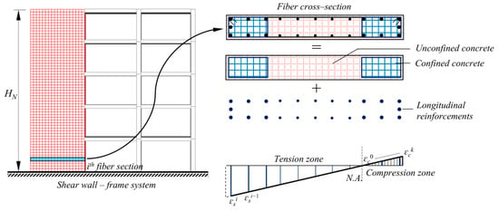
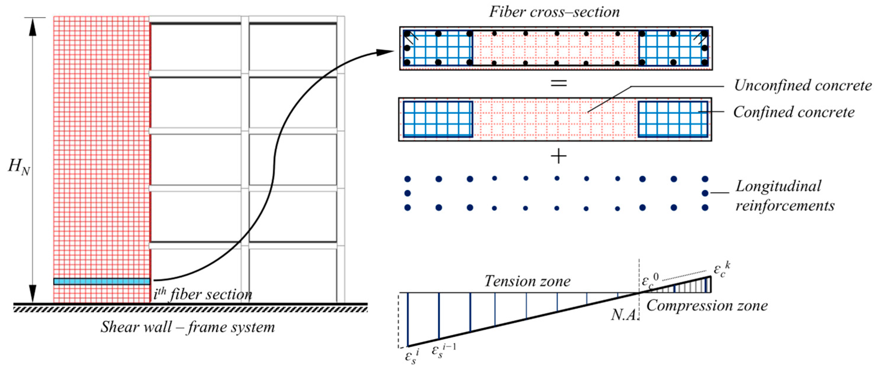
In the nonlinear time history analyses, as specified in TSC-2018 [20], the lumped plasticity model may be utilized for beams and columns. However, the distributed plasticity model is required to capture the inelastic behavior of both uncoupled and coupled shear walls. Thus, the solid shear walls were modeled using nonlinear layered shell elements, incorporating both concrete layers and rebar, as shown in Figure 4. The mesh size for the wall finite elements was maintained at approximately 25 cm × 25 cm. This discretization level was determined through a preliminary convergence analysis, ensuring that further mesh refinement did not significantly alter the member- and system-based structural demands. Initial analyses conducted for these systems revealed that the shear wall elements entered the inelastic range only on the entire first floor and extended to the mid-point of the second floor. It should be noted that this level roughly corresponds the critical shear wall height , which is defined by in the code. Hence, the nonlinear shell model was employed to account for the inelastic behavior up to a building height of , and the regions above this height, defined by , were characterized by linear–elastic material behavior.
Figure 4.
Nonlinear layered shell model for a typical uncoupled shear wall.
To evaluate member-based damage, the limit states defined in TSC—namely Limited Damage (LD) (commonly known as ‘serviceability’), Damage Control (DC) (‘life safety’), and Pre-Collapse Damage (P–CD) (‘collapse prevention’)—were applied to the beams, columns, and shear walls. The summarizing deformation thresholds (concrete/reinforcement strains and plastic rotations) for both distributed and lumped plasticity approaches are given in Table 2.
Table 2.
Deformation-based thresholds for distributed and lumped plasticity concepts in TSC-2018.
3.2. Selection and Scaling of Earthquake Ground Motions
To simulate the nonlinear dynamic responses of the structural systems with joist slabs, a total of eleven real earthquake ground motions were extracted from the PEER Ground Motion Database [43] considering the parameters of shear wave velocity, magnitude, peak value, fault distance, and rupture mechanisms, as summarized in Table 3. TSC-2018 allows two scaling procedures: (a) the simple scaling procedure, which involves amplitude scaling of the individual record to the target spectrum keeping the frequency content of acceleration time history; and (b) the spectral matching procedure, which aims to as perfectly as possible fit between the response spectrum of the ground motion record and target design spectrum [20].
Table 3.
Selected ground motion records and scaling factors.
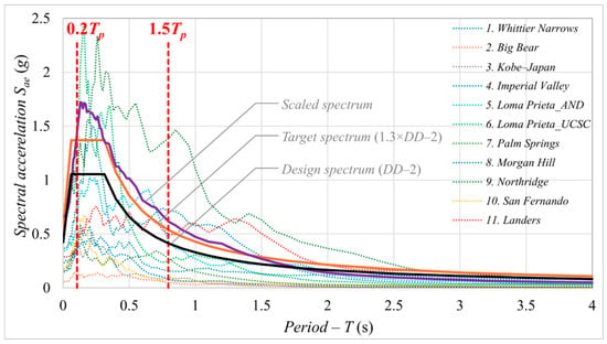
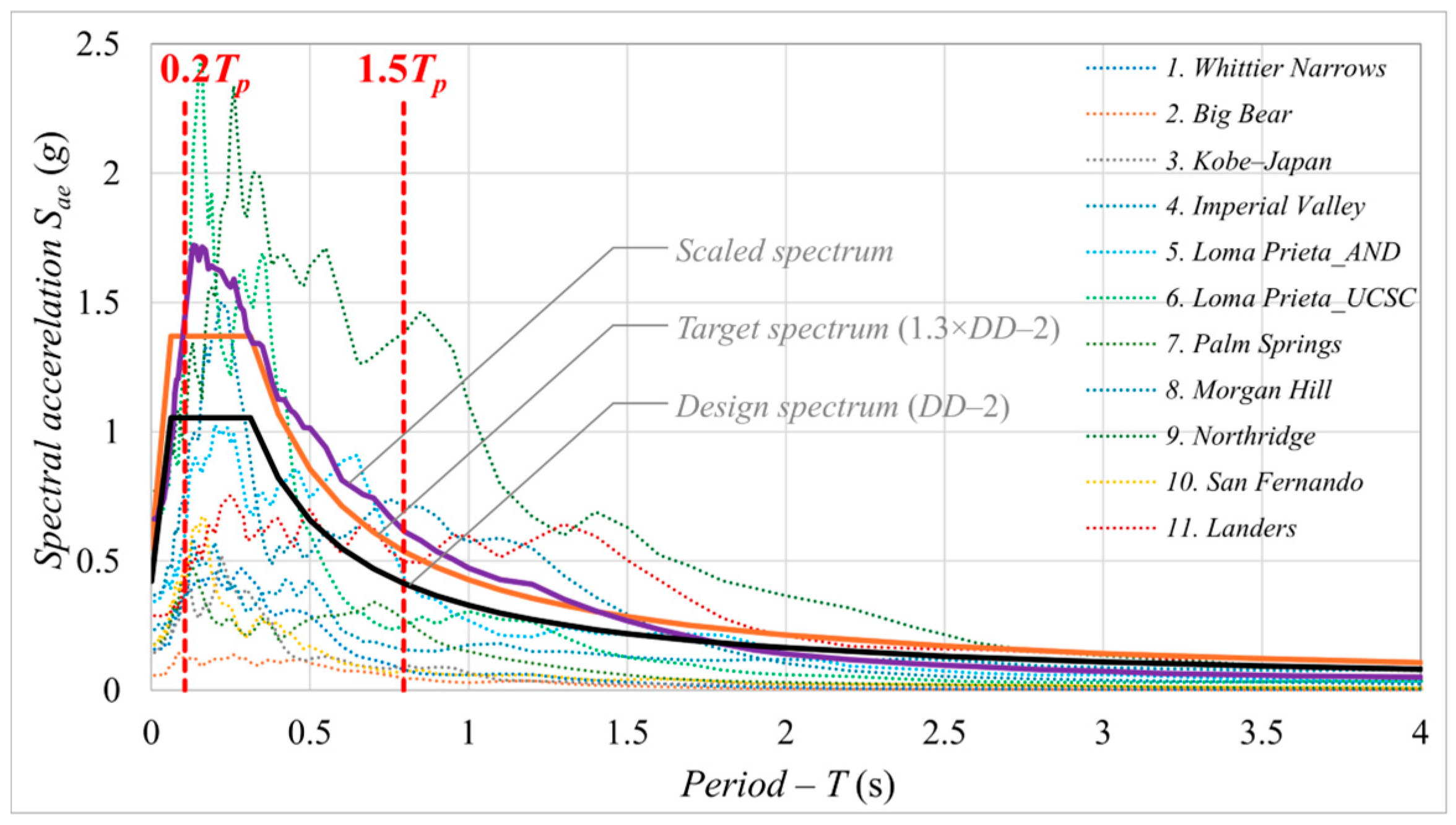
In the study, the simple scaling procedure was used for conducting three-dimensional dynamic analyses. A graphical illustration of this application was given in Figure 5 for the shear wall–frame systems. Accordingly, the acceleration spectrums related to two horizontal components of each ground motion record were combined with the SRSS rule. Subsequently, the amplitudes of the combined spectrums, ranging from 0.2Tp to 1.5Tp, were individually scaled for each record adhering to the rule of being no smaller than the target design spectrum amplified by a factor of 1.3 (see Figure 5). It is also noteworthy that the calculated scaling factors were applied to both horizontal components of the ground motion records, as detailed in Table 3.
Figure 5.
Scaling of earthquake ground motions by the simple procedure.
3.3. Nonlinear Time History Analyses of Structural Systems
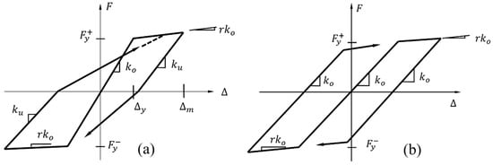
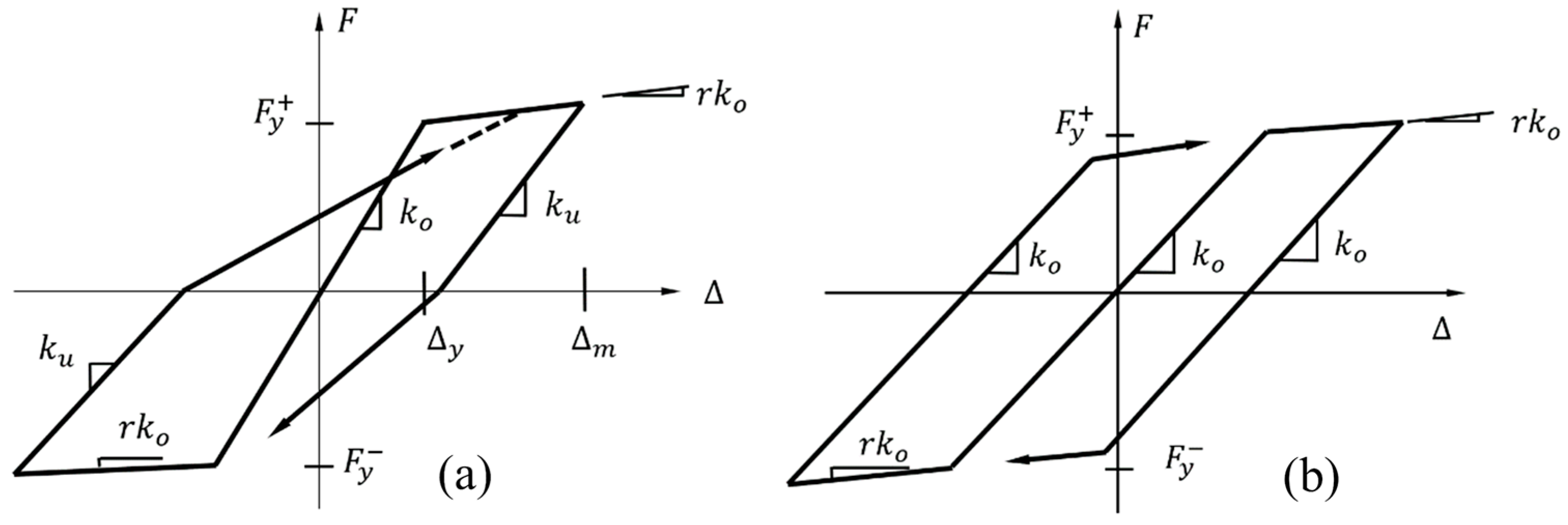
During the numerical analyses, both horizontal components of the earthquake ground motions were jointly applied to X and Y principal directions of the buildings. Given the symmetry and asymmetry in the building floor plans and structural members, the nonlinear time history analyses (NTHA) were performed only in the +X and +Y directions. All NTHAs were conducted using the SAP2000 software [41]. The numerical integrations of the equation of motion were simulated by the Newmark-beta method (with γ = 1/2 and β = 1/4), and the Rayleigh damping, which relates to the mass and stiffness proportional matrices, was implemented into the structural models for the first and second periods. P–Δ effects were incorporated into the equilibrium equations to account for stability-sensitive responses, while their influence on compatibility conditions was neglected for computational efficiency. The inelastic cyclic behavior of the beam plastic hinges was modeled by the Large Takeda model, which accounts for changes in stiffness, whereas the hardening rigid plastic model was applied to the column plastic hinges where the deformations are relatively limited (see Figure 6). The masses transferred from the slabs and beams at each floor level were transferred to the joints with six degrees of freedom. A nonlinear static analysis was performed under a load combination of 1.0G + 0.3Q to form the initial step of the NTHA, during which no plastic deformation occurred in the potential zones.
Figure 6.
(a) Large Takeda model for beams; (b) hardening rigid plastic model for columns.
4. Evaluation and Discussion of Deformation Demands
The member- and system-based response demands, which include the story displacement, inter-story drift, plastic rotation, and strain demands, as well as plastic hinge distributions and performance levels, were determined through the total of 88 bi-directional NTHA conducted in both the X and Y directions. Thereby, the seismic performances of buildings were evaluated and discussed by average values of the response demands. The individual nonlinear analyses confirmed that the shear force and torsional moment demands in all structural members—including the beams, columns, and shear walls—remained below their respective capacities, indicating a fully flexural response without brittle failure mechanisms.
4.1. Story Displacement Demands
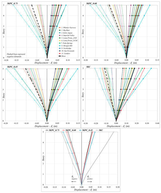
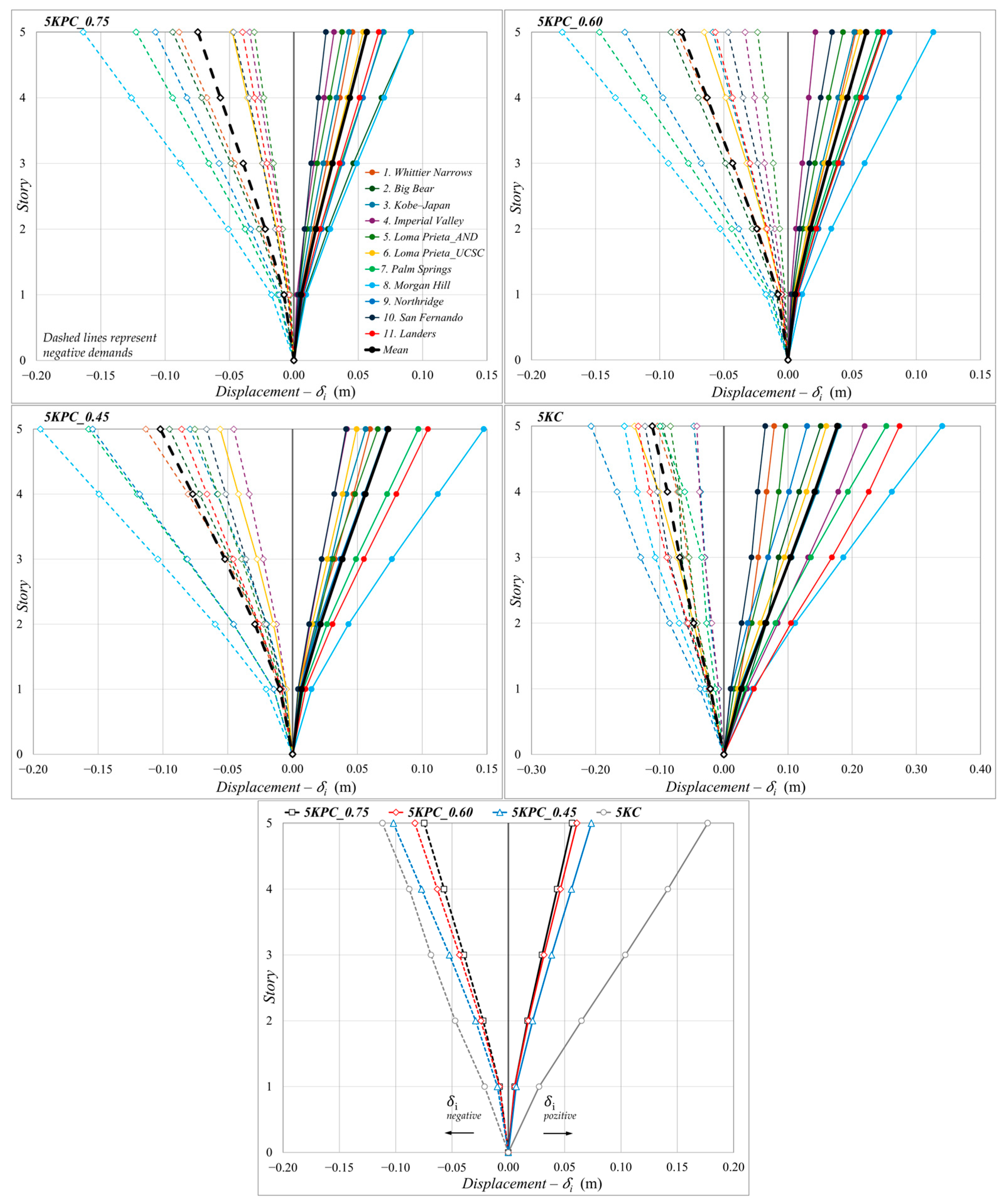
Examining the positive and negative displacement demands and average profiles of the structural systems in Figure 7, as the overturning moment ratio increased, the displacements became more limited depending on the increasing lateral stiffness, as would be expected. This reveals the importance of the shear wall configuration in limiting the second-order effects under seismic loads. The average roof displacement demands of 5KPC_0.60 and 5KPC_0.45 shear wall–frame systems, both designed with high ductility levels, increased by 11% and 36%, respectively, compared to the 5KPC_0.75 with a mixed ductility level. Notably, the percentage variation in the 5KC system was significantly greater at 137%, while the first-floor displacement was much higher, showing an increase of 277%, with the average difference as 184% across all floors of this building. Furthermore, due to inelastic actions at the bottom ends of the first-story columns and the shear wall fibers, the displacement profiles and lateral stiffnesses of the shear wall–frame buildings deviated specifically at the first-floor level, as shown from Figure 7.
Figure 7.
Individual and average displacement profiles for different shear wall ratios.
Based on the numerical analyses of this study, the critical role of shear walls becomes evident to control the displacement demands of RC buildings with joist slabs under seismic events. However, the findings clearly indicated that the current code criteria for the overturning moment ratio are overly conservative, suggesting that the range of for the shear wall–frame systems would be adequate.
4.2. Inter-Story Drift Demands
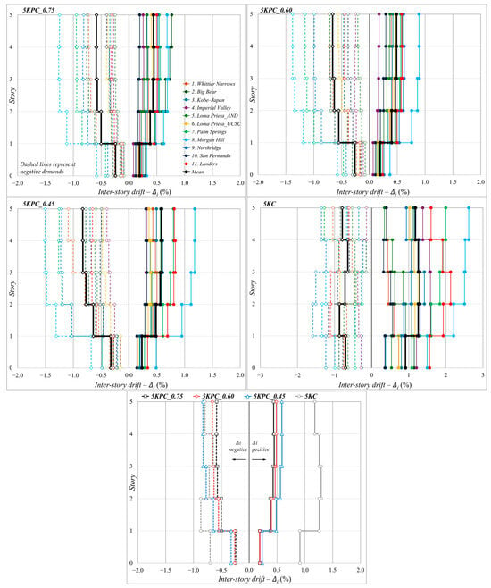
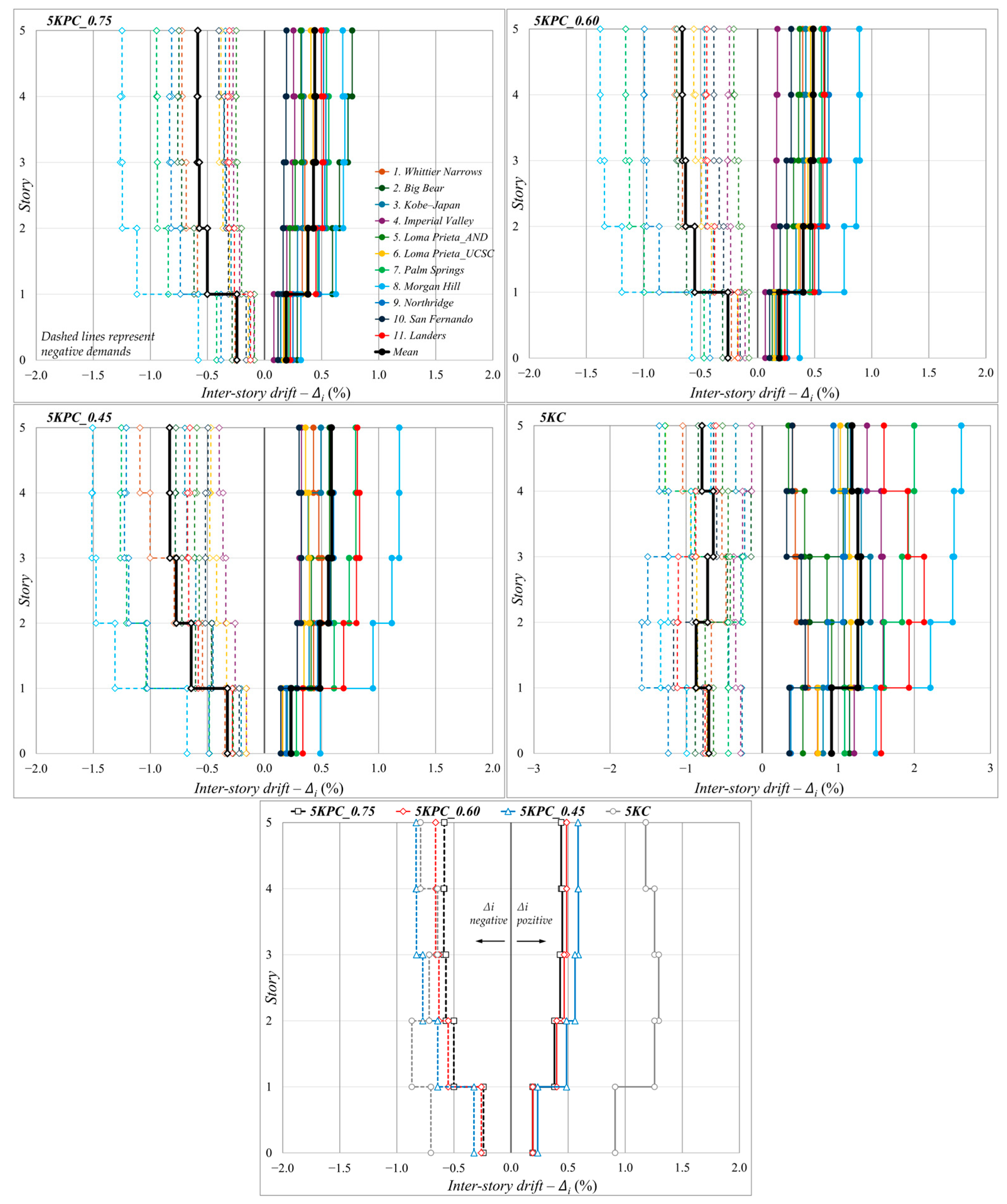
The inter-story drift profiles presented in Figure 8, which indicate the relative displacement ratio between two adjacent stories, highlighted that the lateral stiffness provided by shear walls effectively limited drift demands regardless of the shear wall quantity or the selected ductility level. It should be noted that the first-story drifts in the shear wall–frame systems were overly limited (below 0.5%), and the shear wall quantity and configuration did not have a noticeable effect on the drift demands in the upper floors. However, the beam–column frame system (5KC) was ineffective at controlling lateral displacements under seismic actions, as shown in Figure 8. The average drifts calculated for the systems 5KPC_0.60, 5KPC_0.45, and 5KC—designed with high ductility—increased by 13%, 42%, and 277%, respectively, compared to 5KPC_0.75 with mixed ductility level. It can also be noted that the relative difference in the drift demands closely aligned with those obtained for the displacements.
Figure 8.
Individual and average drift distributions for different shear wall ratios.
The numerical simulations of this study are highly consistent with the particular damage surveys of Marmara and Kahramanmaraş earthquakes. A significant number of heavily damaged frame-only buildings with joist slabs experienced high levels of drift demands, resulting in concentrated deformation predominantly in the ground-story columns. The seismic vulnerability of these buildings became even higher with low-quality materials and non-engineered construction practices [9,12,13,14]. Therefore, the specified provisions regarding the use of shear walls have gained prominence to limit the drifts in the RC building systems that incorporate both joists and conventional slabs. It is important to note that the overturning moment ratio of , which is directly associated with the amount of shear walls within the structural system, is capable of resisting the design-level seismic events.
4.3. Story Shear Forces
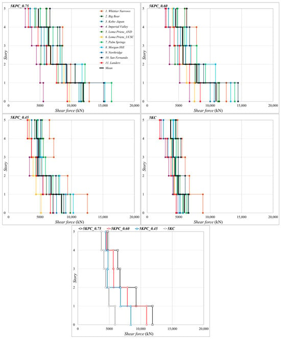
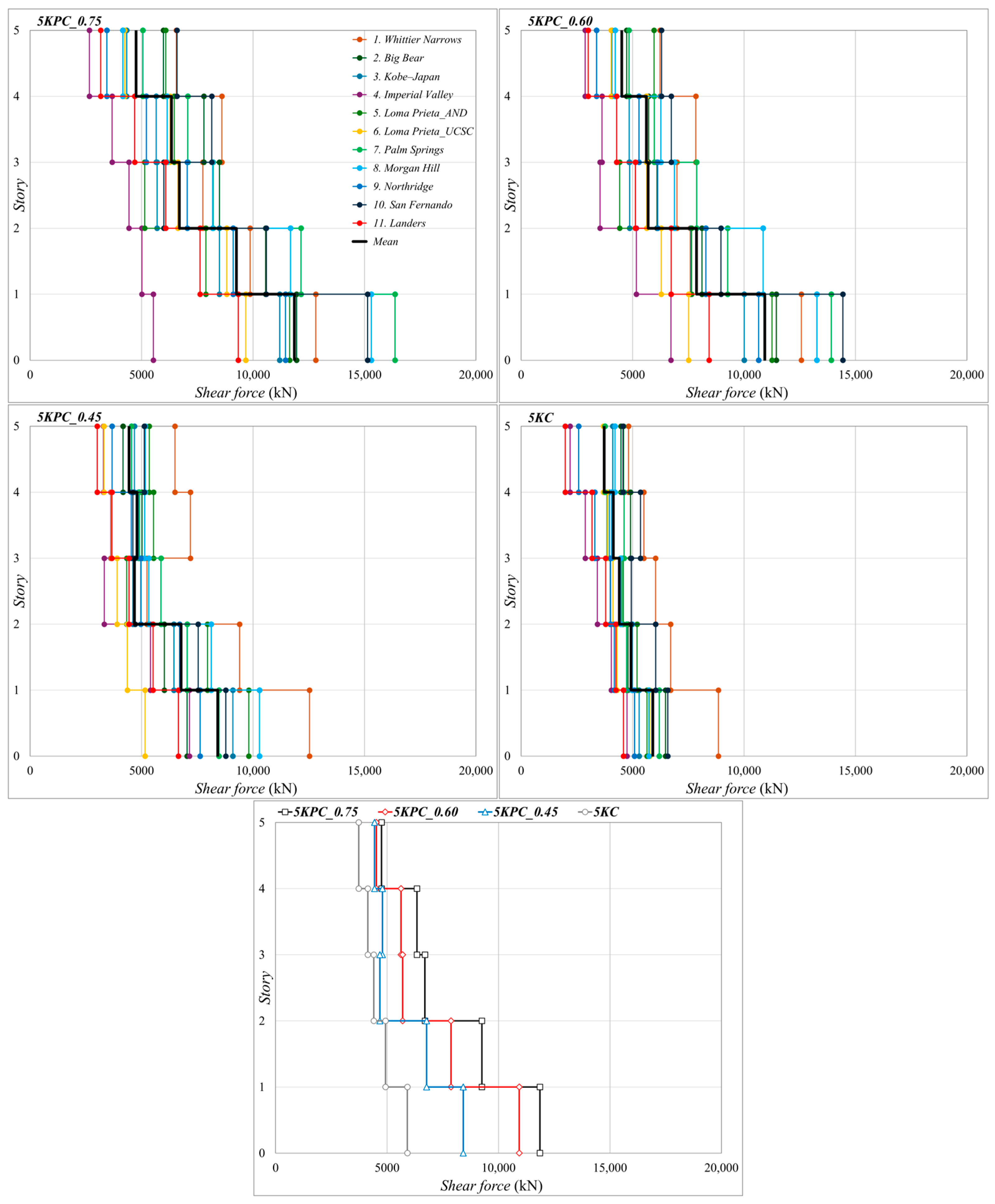
Upon examining the individual and average distributions of story shear forces in the RC shear wall–frame systems with varying ductility and overturning moment ratios, as well as the frame-only system in Figure 9, a significant increase in shear demands was observed at the lower floor levels as the quantity of solid shear walls—and consequently the overturning moment ratio—increases. This trend occurs due to the fact that stiffer structural configurations attract higher seismic forces. Conversely, these variations remained more limited in the upper stories.
Figure 9.
Individual and average story shear demands for different shear wall ratios.
Although the 5KPC_0.75 and 5KPC_0.60 systems had different overturning moment ratios, the lateral forces resisted by their vertical members were relatively similar in the upper stories (third to fifth floors) (Figure 9). Compared to the 5KPC_0.75 system with a mixed ductility level, the average base shear demands for the 5KPC_0.60, 5KPC_0.45, and 5KC systems—designed with high ductility—decreased by 8%, 29%, and 50%, respectively. It should also be noted that the proportion of total shear forces carried by the columns in the 5KPC_0.75, 5KPC_0.60, and 5KPC_0.45 shear wall–frame systems were calculated as 20%, 24%, and 33%, respectively, with the remaining shear demands resisted by the shear walls.
4.4. Member-Based Deformation Demands
The plastic rotation and strain demands, which are closely linked to the extent of damage within the structural system, are critical parameters for the performance-based design concept.
4.4.1. Beam Plastic Rotations
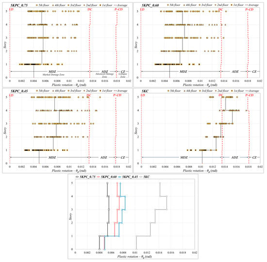
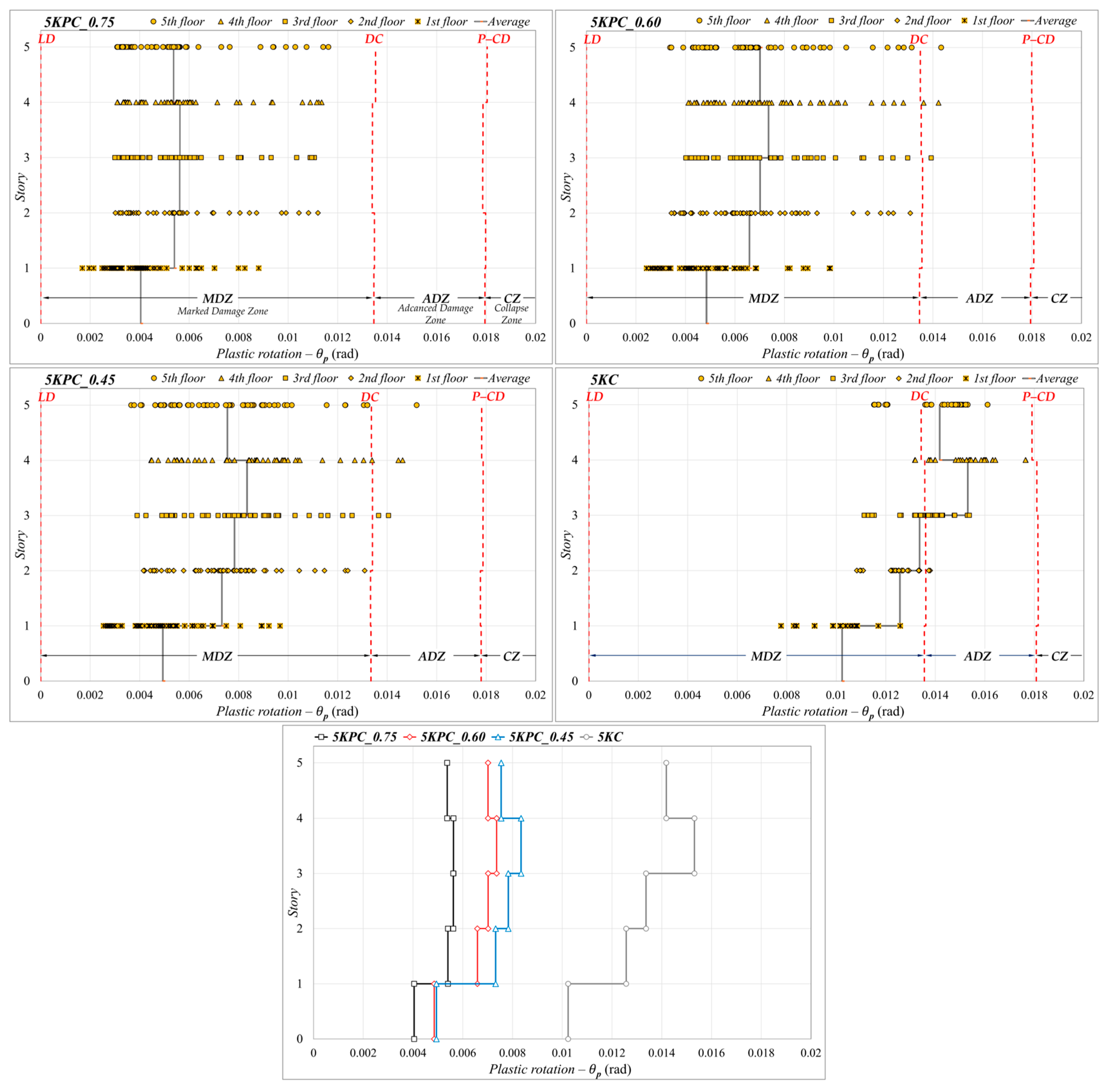
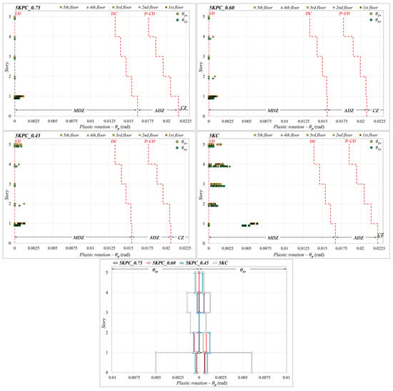
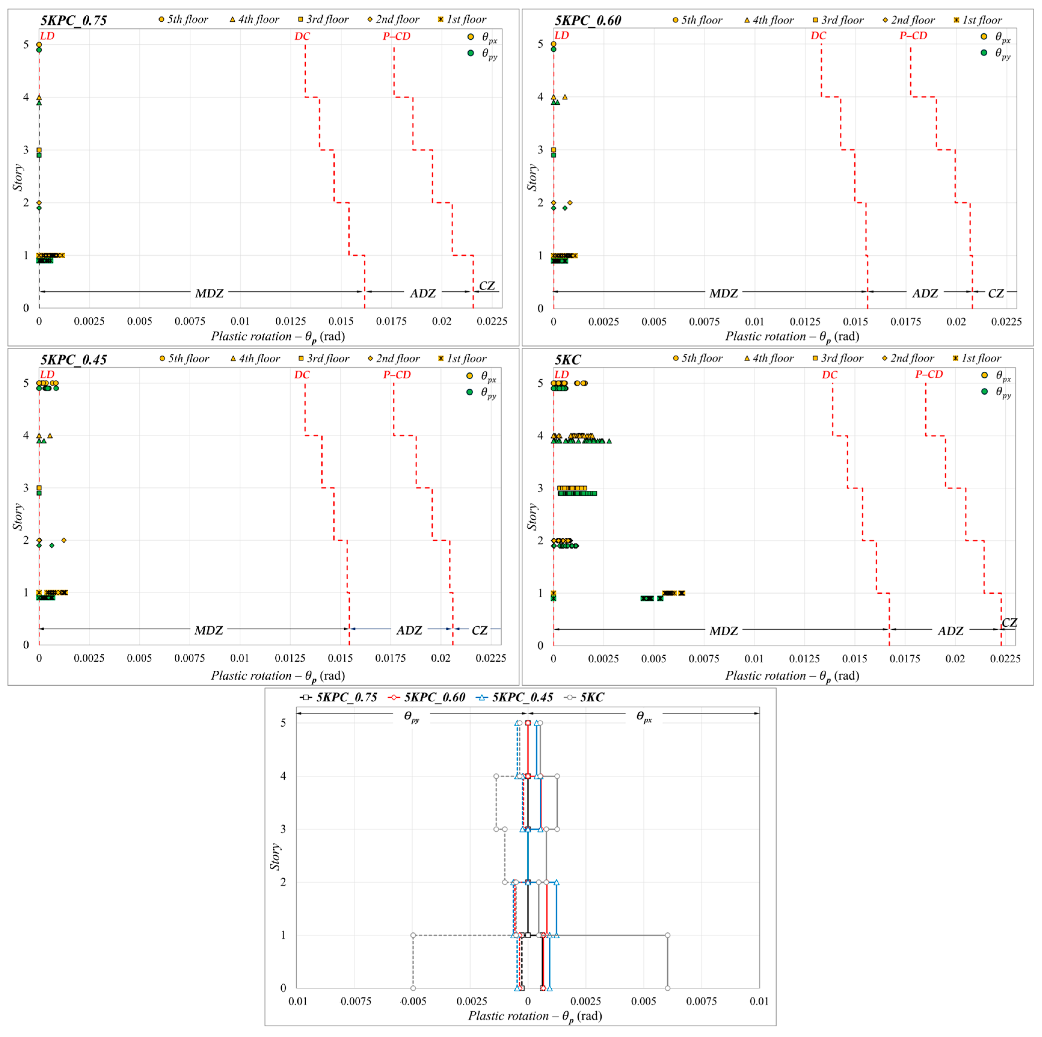
The graphs in Figure 10 illustrate the distribution of average plastic rotation demands in the joist slab structural systems, incorporating the limit states defined in TSC-2018. As the overturning moment ratio in the shear wall–frame systems decreased, the beam plastic rotation demands showed an upward trend, regardless of the ductility level. Regarding this matter, the maximum value of the average rotations across all story levels for the 5KPC_0.60, 5KPC_0.45, and 5KC buildings were greater by 23%, 31%, and 52%, respectively, compared to the 5KPC_0.75 in accordance with the code criteria. At this point, it should be noted that the differences in plastic rotations developed within the shear wall–frame systems were relatively minor when considering the thresholds related to the limit states (LD, DC, and P–CD) in TSC-2018 [20].
Figure 10.
Distributions of beam plastic rotation demands and their mean story-level profiles.
As shown in Figure 10, the plastic deformations in the shear wall–frame systems were mostly distributed in the Marked Damage Zone (MDZ) between the LD and CD limit states. However, as the overturning moment ratio decreased, there was a noticeable shift towards the Advanced Damage Zone (ADZ) between the DC and P–CD limit states. In the case of the 5KC frame system, unlike the other systems, the plastic demands in the first story were within the MDZ but progressively increased in the upper stories, surpassing into the ADZ (Figure 10). This result confirms that many joist slab structures with low-quality materials and non- or low-engineered construction sustained moderate to heavy damage in many earthquake-affected provinces.
4.4.2. Column Plastic Rotations
Based on the distributions presented in Figure 11, all the column plastic hinges in the 5KPC_0.75 developed only at the base of the ground-story columns, and the column deformations were very close to the linear–elastic limit . Note that the maximum plastic rotation is under the individual ground motion records. As the overturning moment ratio decreased, reaching the threshold of 0.40, some plastic hinges began to form at the upper stories of the structural systems, although the resulting deformations were extremely small (see Figure 11). In other respects, a large number of plastic hinges developed at the column ends of the frame-only system, extending into an advanced range, compared to the shear wall–frame structures, through the yield surfaces (P–M2–M3). However, the column deformations in the 5KC did not exceed the MDZ since it was defined within a wide band, as can be shown in Figure 11.
Figure 11.
Distributions of column plastic rotation demands and their mean story-level profiles.
The maximum values of the plastic rotation demands averaged at the lowest columns of the 5KC building were found to be 5.62, 6.01, and 4.96 times higher than those in the 5KPC_0.75, 5KPC_0.60, and 5KPC_0.45 systems, respectively. This outcome revealed the crucial role of the shear walls at controlling the damage to the RC buildings with one-way joist slabs subjected to seismic actions.
4.4.3. Fiber Strains in Shear Walls
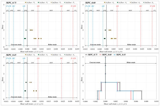
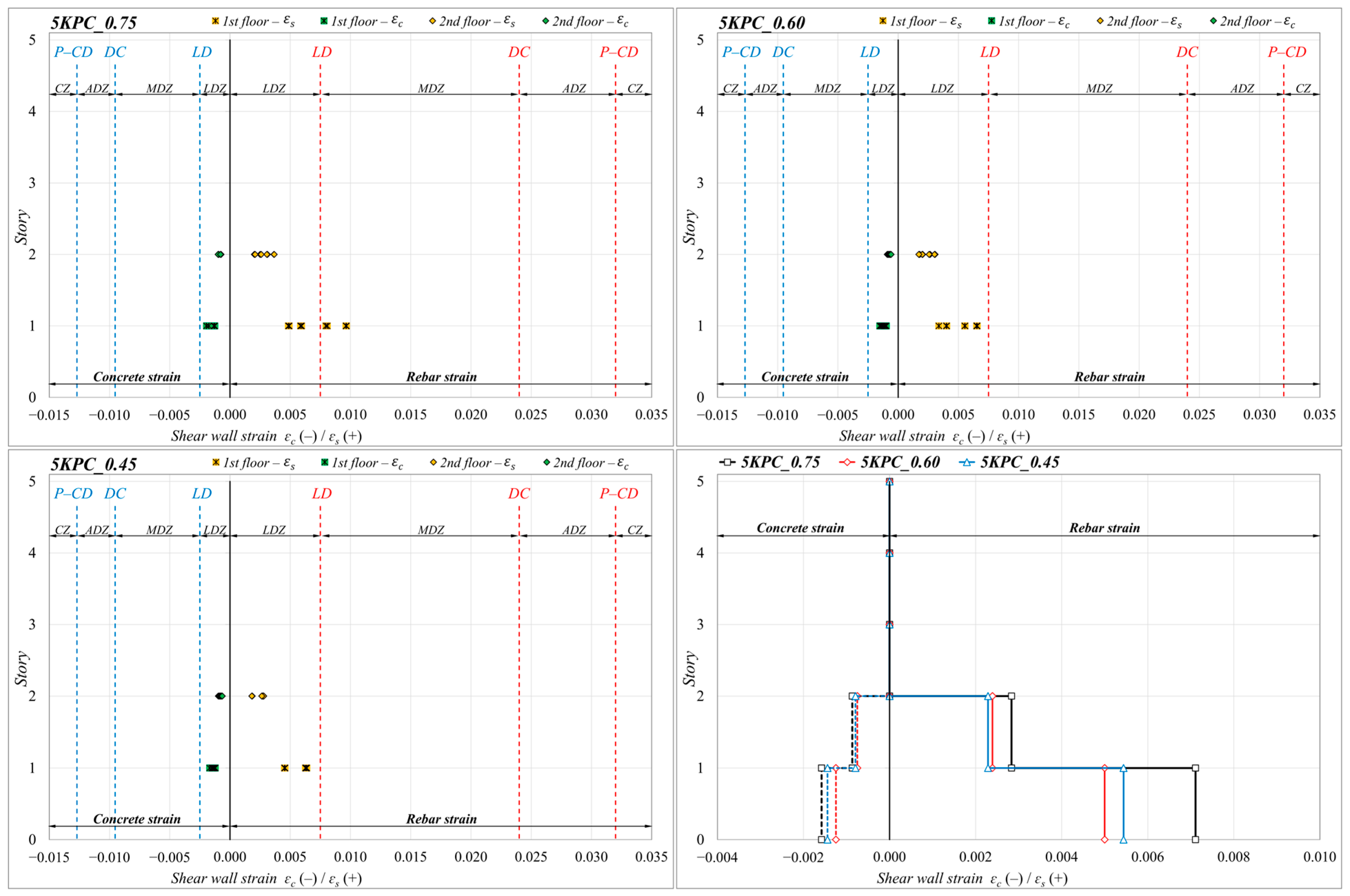
The results of the conducted NTHA indicated that the concrete and rebar strains in the shear wall were nearly identical, regardless of the overturning moment ratio and selected ductility level. Accordingly, both strain demands fell within the Limited Damage Zone (LDZ) where the damages did not reach the LD limit state (see Figure 12). It is noteworthy that the average strains in the fiber sections of the 5KPC_0.75 system were slightly higher by ≈30% than those in other buildings, as the uncoupled shear walls resisted more shear forces under seismic loads.
Figure 12.
Concrete and rebar strains in uncoupled shear walls and their mean story-level profiles.
When discussing the inelastic behaviors of the structural components under real acceleration time histories, the code provision of leads to an increased safety margin concerning the plastic deformations. Therefore, it can be concluded that when the structural systems of such buildings are jointly designed with shear walls and frames of high ductility levels, through the capacity design principles, the stipulated performance objective will be achieved within the range of .
4.5. Distribution of Plastic Hinge Formations
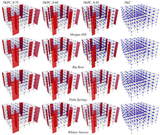
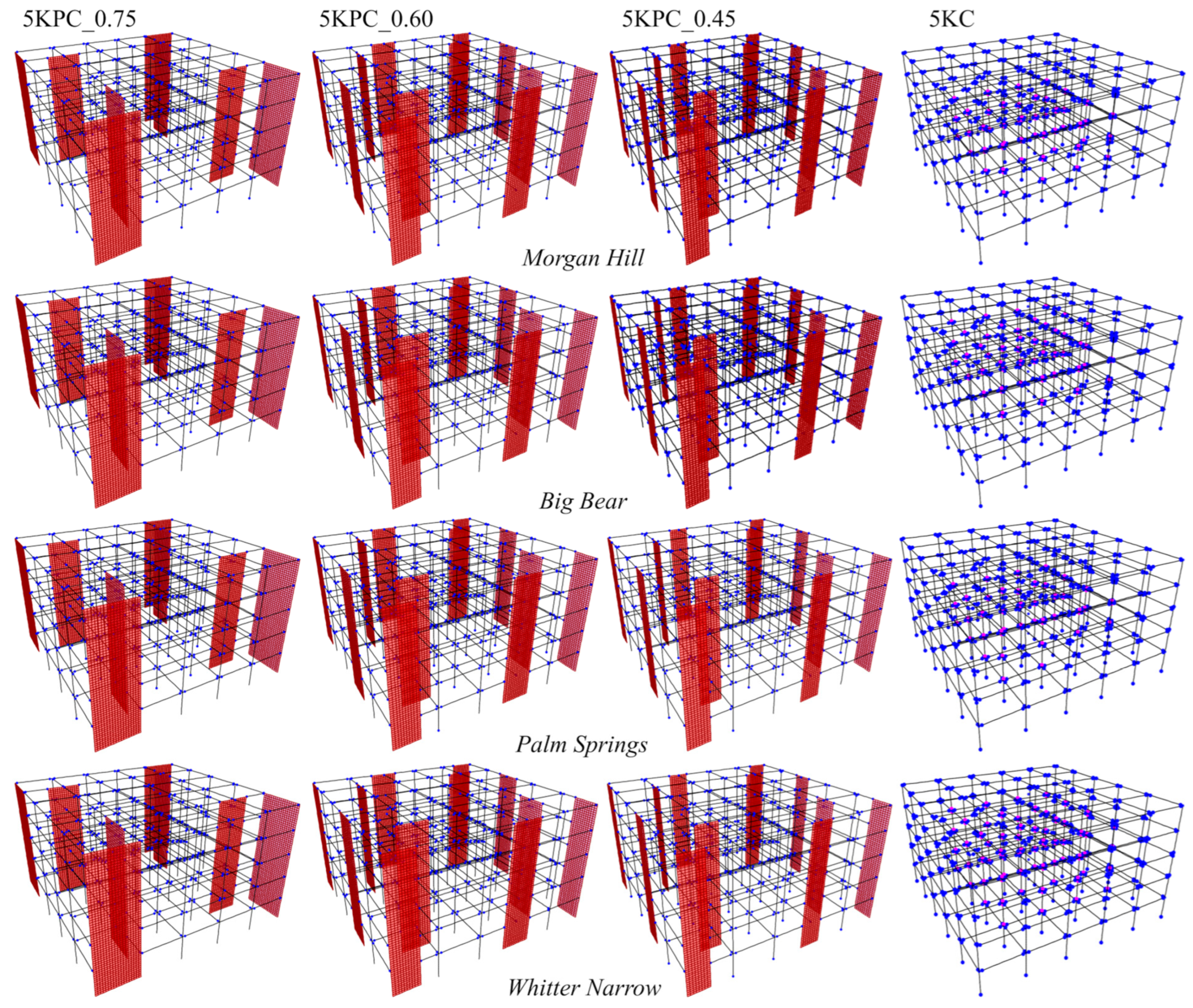
The distribution of the plastic hinges within the structural systems varied depending on the selected ground motion records. While the hinge formations from some individual records (such as Landers, Loma Prieta/Anderson) were pretty limited for the shear wall–frame systems, the number of plasticized sections rapidly increased for other records, including Morgan Hill, Big Bear, Palm Springs, and Whittier Narrow. Regarding the most unfavorable plastic hinge distributions illustrated in Figure 13, the 5KPC_0.75 system displayed the beam sway mechanisms though most plastic hinges developed at the beam ends. However, as the overturning moment ratio decreased and the number of beam plastic hinges increased, new plastic hinges appeared at the bottom of the lowest columns while the number of finite element sections exhibiting inelastic behavior steadily increased (Table 4). It is noteworthy that no stability problems or column sway mechanisms, which could cause soft-story collapses, occurred despite the development of undesirable joint mechanisms because of the yielding of the beam and column faces framing into the joints in the upper stories.
Figure 13.
Most unfavorable plastic hinge formations for structural systems.
Table 4.
Proportion of the total yielded plastic hinges.
In contrast to this behavior, in the 5KC system, almost all beam potential hinge regions and a significant portion of column ends yielded and entered the plastic stage for the specific earthquake records, as quantitatively detailed in Table 4. Eventually, as demonstrated in Figure 13, the column sway (or story sway) mechanisms were observed during the nonlinear dynamic analyses of specific records such as Big Bear, Palm Springs, and Whittier Narrow. This result was highly consistent with the damage and collapse modes experienced in sub-standard RC buildings having joist slab systems in particular after the Adana-Ceyhan 1998, Marmara 1999, Van 2011, and Kahramanmaraş 2023 earthquakes [7,8,12,13,14,44].
4.6. Importance of Shear Wall Use on Member-Based Performance Levels
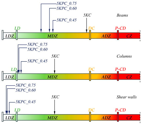
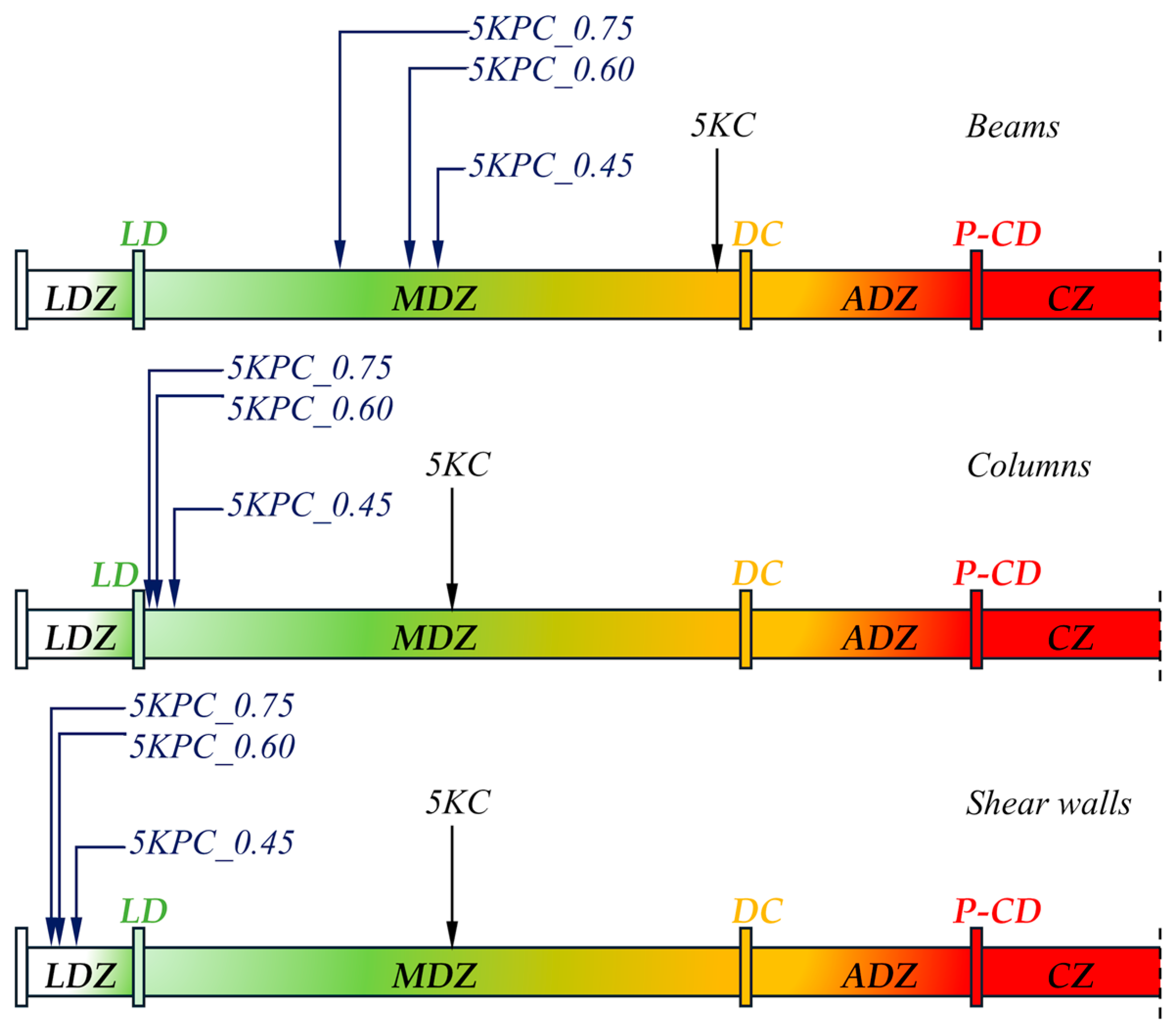
Based on the member-based plastic rotation and strains within the structural systems, the final performances of overall structural member were comparatively illustrated in Figure 14. From this point of view, variations in the overturning moment ratio did not significantly affect the beam performance; thus, the damages in the shear wall–frame systems fell within the MDZ. Conversely, while the beams of 5KC system were also in the same zone, they came up to the DC limit state due to the lack of sufficient stiffness provided by the frames under seismic loads. Regarding the column performances, the deformations in the shear wall–frame systems were located near the linear–elastic limit, regardless of the overturning moment ratio, as shown in Figure 14. In contrast, the column damages in the frame-only system progressed towards the mid-range of the MDZ due to the joint and column sway mechanisms. This result strongly supports the code provisions with respect to the use of a particular amount of shear wall in the seismic design of the structural systems with one- or two-way joist slabs.
Figure 14.
Member-based performances levels.
Similar to the findings for the column performances, as shown in Figure 14, the fact that the strains in the solid shear walls performing in the LDZ region were very close to each other revealed that the shear wall configuration providing the design rule of , as well as the selected of ductility level for such RC systems, had minimal impact during the design-based seismic events.
5. Conclusions
In the numerical study presented, the influence of shear wall quantity on the seismic behavior of RC buildings featuring one-way joist slabs was evaluated, referencing the design provisions outlined in TSC-2018. In this sense, a typical five-story RC building was examined by four structural systems that shared similar slab properties and layouts but varied in their overturning moment ratios . The seismic performances of buildings were evaluated by means of the member- and system-based seismic response demands, as well as the causes of extensive damage and collapse observed in these buildings during the catastrophic earthquakes in Türkiye.
The following conclusions were drawn from the nonlinear time history analyses conducted:
- The roof displacements for the shear wall–frame systems (5KPC_0.60 and 5KPC_0.45) with high ductility increased by 11% and 36%, respectively, compared to the 5KPC_0.75, which adhered to the code criteria. However, the variation in the frame-only system (5KC) was much greater by 137%. While the shear wall quantities, ranging from 0.45 to 0.75, did not have a noticeable impact on both displacement and drift demands across all floors, the 5KC system was inadequate in controlling the lateral deformations during the design-based seismic events.
- The plastic deformations in beams of the shear wall–frame systems were mostly distributed within the Marked Damage Zone (MDZ). It was evident that, as the overturning moment ratio decreased, there was a noticeable shift towards the Advanced Damage Zone (ADZ). In the case of the 5KC, unlike the other systems, the beam demands in the first story were within the MDZ but progressively increased in the upper stories, surpassing into the ADZ.
- The column plastic hinges in the 5KPC_0.75 developed only at the lowest column ends, with the deformations near the linear–elastic limit. Upon decreasing the threshold of 0.40, some plastic hinges began to form at the upper stories, although the resulting deformations were extremely small. In other respects, a large number of plastic hinges developed at the column ends of the frame-only system, extending into an advanced range compared to the shear wall–frame structures. It is noteworthy that the maximum values of the average demands at the lowest columns of the 5KC were found to be 4.62, 5.01 and 3.95 times higher than those in the 5KPC_0.75, 5KPC_0.60 and 5KPC_0.45 systems, respectively.
- The strains in concrete and reinforcing rebars of the uncoupled shear walls were nearly identical and located within the Limited Damage Zone (LDZ). It can be noted that the strains observed in the fiber sections of the 5KPC_0.75 are ≈30% higher than those in other buildings, as the shear walls resisted more shear forces due to seismic loads.
- Regarding the formation of plastic hinges within the structural systems, the 5KPC_0.75 displayed the beam sway mechanisms though most plastic hinges developed at the beam ends. However, as the overturning moment ratio decreased and the number of beam plastic hinges increased, new plastic hinges appeared at the base of the ground-story columns while the number of inelastic fiber sections increased. While no stability issues leading to collapse arose in the shear wall–frame systems, the column sway mechanisms were observed in the 5KC system during some specific records. This is highly consistent with the collapse modes experienced, particularly in sub-standard buildings in the previous Turkish earthquakes.
- The variations in the overturning moment ratio had little impact on the member-based damage levels of the shear wall–frame systems. Although the beams and columns of the 5KC system were also in the same zone (MDZ), they came up to the damage control limit state due to the lack of sufficient stiffness provided by the frames under the seismic loads.
- The numerical simulations of this study are highly consistent with the damage surveys of destructive earthquakes (Marmara 1999, Van 2011 and Kahramanmaraş 2023) in Türkiye. The seismic vulnerability of these buildings became even higher with low-quality materials and non-engineered construction practices. Consequently, the current seismic code provisions regarding the incorporation of shear walls have gained prominence in limiting the deformation demands in the RC building systems with both joists and conventional slabs.
When assessing the inelastic behaviors in the structural components under real acceleration time histories, the code provision of leads to an increased safety margin regarding the plastic deformations. Thus, it can be concluded that when the structural systems of such buildings are jointly designed with shear walls and frames of high ductility levels—through the capacity design principles—the stipulated performance objectives will be achieved within the overturning moment ratio range of .
Higher mode effects and P-Δ effects would indeed be more dominant for higher buildings consisting solely of ductile frames or for those that do not comply with code requirements. In such cases, different failure mechanisms might emerge due to the increased sensitivity to lateral instability.
Author Contributions
Conceptualization, U.H.; methodology, U.H. and M.S.K.; software, U.H. and M.S.K.; validation, M.S.K.; formal analysis, M.S.K.; writing—original draft preparation, U.H. and M.S.K.; writing—review and editing, U.H.; visualization, U.H.; supervision, U.H. All authors have read and agreed to the published version of the manuscript.
Funding
This research received no external funding.
Data Availability Statement
Modeling and analysis data, as well as additional inquiries, are available from the corresponding author upon request.
Conflicts of Interest
The authors declare no conflicts of interest.
Abbreviations
The following abbreviations are used in this manuscript:
| ADZ | Advanced damage zone |
| CZ | Collapse zone |
| DC | Damage control level |
| LD | Limited damage level |
| LDZ | Limited damage zone |
| MDZ | Marked damage zone |
| NTHA | Nonlinear time history analysis |
| P-CD | Pre-collapse damage level |
| SDC | Seismic design class |
| SRSS | Square root of the sum of squares |
| TSC | Turkish seismic code |
References
- Dönmez, C. Seismic performance of wide-beam infill-joist block RC frames in Turkey. J. Perform. Constr. Facil. 2015, 29, 04014026. [Google Scholar] [CrossRef] [Scilit]
- Akyıldız, A.T.; Girgin, K. Investigation on earthquake safety of buildings constructed for the urban transformation of Istanbul. Dokuz Eylul Univ. Fac. Eng. J. Sci. Eng. 2017, 19, 100–121. (In Turkish) [Google Scholar] [CrossRef] [Scilit]
- Domínguez, D.; López-Almansa, F.; Benavent-Climent, A. Would RC wide-beam buildings in Spain have survived Lorca earthquake (11-05-2011)? Eng. Struct. 2016, 108, 134–154. [Google Scholar] [CrossRef] [Scilit]
- Gómez-Martínez, F.; Alonso-Durá, A.; De Luca, F.; Verderame, G.M. Ductility of wide beam RC frames as lateral resisting system. Bull. Earthq. Eng. 2016, 14, 1545–1569. [Google Scholar] [CrossRef] [Scilit]
- Gómez-Martínez, F.; Alonso-Durá, A.; De Luca, F.; Verderame, G.M. Seismic performances and behaviour factor of wide-beam and deep-beam RC frames. Eng. Struct. 2016, 125, 107–123. [Google Scholar] [CrossRef] [Scilit]
- Lalaj, O.; Çevik, O.; Kayhan, A.H. Seismic Demand on 4-Story Limited Ductility Class Frames Designed according to TBEC2018. In Proceedings of the 5th International Conference on Earthquake and Seismology (5ICEES), Ankara, Türkiye, 8–11 October 2019. [Google Scholar]
- Wenk, T.; Lacave, C.; Peter, K. The Adana—Ceyhan Earthquake of June 27, 1998; Report on the Reconnaissance Mission from 6–12 July 1998 of the Swiss Society of Earthquake Engineering and Structural Dynamics (SGEB); SGEB: Zurich, Switzerland, 1998. [Google Scholar]
- Sezen, H.; Elwood, K.J.; Whittaker, A.S.; Mosalam, K.M.; Wallace, J.W.; Stanton, J.F. Structural Engineering Reconnaissance of the 17 August 1999 Kocaeli (Izmit), Turkey; Report No. 2000/09; Pacific Earthquake Engineering Research Center; University of California: Berkeley, CA, USA, 2000. [Google Scholar]
- Saatcioglu, M.; Mitchell, D.; Tinawi, R.; Gardner, N.J.; Gillies, A.G.; Ghobarah, A.; Anderson, D.L.; Lau, D. The August 17, 1999, Kocaeli (Turkey) earthquake damage to structures. Can. J. Civ. Eng. 2001, 28, 715–737. [Google Scholar] [CrossRef] [Scilit] [PubMed]
- Doğangün, A. Performance of reinforced concrete buildings during the May 1, 2003 Bingöl earthquake in Turkey. Eng. Struct. 2004, 26, 841–856. [Google Scholar] [CrossRef] [Scilit]
- Kızılkanat, A.; Koçak, A.; Coşar, A.; Güney, D.; Selçuk, M.; Yıldırım, M. Technical Investigation Report of 23rd of October 2011 Van Earthquake; Yıldız Technical University: Istanbul, Türkiye, 2011. [Google Scholar]
- METU- Earthquake Engineering Research Center. Site Observation of Seismic and Structural Damage on Van Earthquake of Mw = 7.2, 23 October 2011; Report No. METU/EERC 2011–04; Middle East Technical University Earthquake Engineering Research Center: Ankara, Türkiye, 2011. [Google Scholar]
- Dilsiz, A.; Gunay, S.; Mosalam, K.; Miranda, E.; Arteta, C.; Sezen, H.; Fischer, E.; Hakhamaneshi, M.; Hassan, W.; ALhawamdeh, B.; et al. StEER: 2023 Mw 7.8 Kahramanmaras, Türkiye Earthquake Sequence Preliminary Virtual Reconnaissance Report (PVRR); Structural Extreme Events Reconnaissance (StEER) and Earthquake Engineering Research Institute (EERI): Oakland, CA, USA, 2023. [Google Scholar]
- Çetin, K.Ö.; Ilgaç, M.; Çakır, E. Preliminary Reconnaissance Report on 6 February 2023, Pazarcık Mw = 7.7 and Elbistan Mw = 7.6, Kahramanmaraş-Türkiye Earthquakes; METU/EERC 2023-01; Middle East Technical University Earthquake Engineering Research Center: Ankara, Türkiye, 2023. [Google Scholar]
- EN 1998-1; Design of Structures for Earthquake Resistance—Part 1: General Rules, Seismic Actions and Rules for Buildings. The European Committee for Standardization (CEN): Bruxelles, Belgium, 2004.
- UBC-97; Uniform Building Code. International Conference of Building Officials: Whittier, CA, USA, 1997.
- IBC 2018; International Building Code. International Code Council: Country Club Hills, IL, USA, 2018.
- NZS 3101-1; Concrete Structures Standard—The Design of Concrete Structures. Standards New Zealand: Wellington, New Zealand, 2006.
- ASCE/SEI 41-17; Seismic Evaluation and Retrofit of Existing Buildings. American Society of Civil Engineers: Reston, VA, USA, 2017.
- TSC-2018; Turkish Building Earthquake Code. The Disaster and Emergency Management Presidency: Ankara, Türkiye, 2018.
- NTC. Aggiornamento delle «Norme Tecniche per le Costruzioni»; D.M. 17/01/2018 G.U.R.I. No. 42; Ministero Delle Infrastrutture e Dei Trasporti: Rome, Italy, 2018. (In Italian) [Google Scholar]
- NCSE-02; Norma de Construcción Sismorresistente: Parte General y Edificación. Committee for the Development of Seismic Codes, Spanish Ministry of Construction: Madrid, Spain, 2002.
- EAK 2000; Greek Code for Seismic Resistant Structures. Organization for Earthquake Resistant Planning and Protection: Athens, Greece, 2000.
- Karaaslan, E. Seismic Performance Assessment of Wide Beam Infill Joist Block Frame Structures in Turkey. Master’s Thesis, Middle East Technical University, Ankara, Türkiye, 2015. [Google Scholar]
- Dönmez, C.; Karaarslan, E.; Erberik, M.A. Fragility analysis of wide-beam infill-joist block RC frames. J. Fac. Eng. Archit. Gazi Univ. 2022, 37, 159–173. (In Turkish) [Google Scholar] [CrossRef] [Scilit]
- TSC-2007; Specification of Buildings to be Built in Disaster Areas. The Ministry of Public Works and Settlement: Ankara, Türkiye, 2007.
- Vielma, J.; Barbat, A.H.; Oller, S. Seismic performance of waffled-slab floor buildings. Proc. Inst. Civ. Eng. Struct. Build. 2009, 162, 169–182. [Google Scholar] [CrossRef] [Scilit]
- Burak, B.; Çömlekoğlu, H.G. Effect of shear wall area to floor area ratio on the seismic behavior of reinforced concrete buildings. J. Struct. Eng. 2013, 139, 1928–1937. [Google Scholar] [CrossRef] [Scilit]
- Günel, A.O. Influence of the Shear Wall Area to Floor Area Ratio on the Seismic Performance of Existing Reinforced Concrete Buildings. Master’s Thesis, Middle East Technical University, Ankara, Türkiye, 2013. [Google Scholar]
- Turker, K.; Gungor, I. Seismic performance of low and medium-rise RC buildings with wide-beam and ribbed-slab. Earthq. Struct. 2018, 15, 383–393. [Google Scholar] [CrossRef]
- Shahzad, M.M.; Zhang, X.; Wang, X.; Abdulhadi, M.; Xiao, Y.; Fan, B. Plastic deformation analysis of a new mega-subcontrolled structural system (MSCSS) subjected to seismic excitation. Buildings 2022, 12, 987. [Google Scholar] [CrossRef] [Scilit]
- Behzadinia, F.; Erfani, S. The seismic demand evaluation of columns at the intersection of SPSWs. J. Constr. Steel Res. 2025, 227, 109361. [Google Scholar] [CrossRef] [Scilit]
- Ruggieri, S.; Porco, F.; Uva, G. A practical approach for estimating the floor deformability in existing RC buildings: Evaluation of the effects in the structural response and seismic fragility. Bull. Earthq. Eng. 2020, 18, 2083–2113. [Google Scholar] [CrossRef] [Scilit]
- Gülkan, P.L.; Utkutuğ, D. Minimum design criteria for earthquake safety of school buildings. Türkiye Mühendislik Haberleri 2003, 425, 13–22. (In Turkish) [Google Scholar]
- Soydaş, O. Evaluation of Shear Wall Indexes for Reinforced Concrete Buildings. Master’s Thesis, Middle East Technical University, Ankara, Türkiye, 2009. [Google Scholar]
- Tekel, H. Evaluation of usage of 1% shear wall in reinforced concrete structures. Turk. Eng. News 2006, 444–445, 57–63. (In Turkish) [Google Scholar]
- Wallace, J.W. New methodology for seismic design of reinforced concrete shear walls. J. Struct. Eng. 1994, 120, 863–884. [Google Scholar] [CrossRef] [Scilit]
- TSC-1998; Specification of Buildings to be Built in Disaster Areas. The Ministry of Public Works and Settlement: Ankara, Türkiye, 1998.
- Kurt, M.Ş. A Parametric Study on Impact of Shear-Wall Ratio in Reinforced Concrete Systems with Combined Ductility Level in the Frame of Nonlinear Time History Analyses. Master’s Thesis, Balikesir University, Balikesir, Türkiye, 2023. (In Turkish) [Google Scholar]
- Mander, J.B.; Priestley, M.J.N.; Park, R. Theoretical stress–strain model for con-fined concrete. J. Struct. Eng. 1988, 114, 1804–1826. [Google Scholar] [CrossRef] [Scilit]
- CSI SAP2000; Integrated Software for Structural Analysis and Design Program. Computers and Structures Inc.: Berkeley, CA, USA, 2019.
- Deierlein, G.G.; Reinhorn, A.M.; Willford, M.R. Nonlinear Structural Analysis for Seismic Design, A Guide for Practicing Engineers; NEHRP Seismic Design Technical Brief No. 4; Applied Technology Council (ATC): Redwood City, CA, USA, 2010. [Google Scholar]
- PEER-Ground Motion Database. NGA-West2—Shallow Crustal Earthquakes in Active Tectonic Regimes; Pacific Earthquake Engineering Research Center, University of California Berkeley. Available online: https://peer.berkeley.edu/peer-strong-ground-motion-databases (accessed on 3 January 2025).
- Adalier, K.; Aydingun, O. Structural engineering aspects of the 27 June 1998 Adana-Ceyhan (Turkey) earthquake. Eng. Struct. 2001, 23, 343–355. [Google Scholar] [CrossRef] [Scilit]

Disclaimer/Publisher’s Note: The statements, opinions and data contained in all publications are solely those of the individual author(s) and contributor(s) and not of MDPI and/or the editor(s). MDPI and/or the editor(s) disclaim responsibility for any injury to people or property resulting from any ideas, methods, instructions or products referred to in the content. |
© 2026 by the authors. Licensee MDPI, Basel, Switzerland. This article is an open access article distributed under the terms and conditions of the Creative Commons Attribution (CC BY) license.