


Abstract
To improve the design efficiency and structural safety of pile–panel retaining walls in high-slope engineering, this study investigates the load-reduction effect of expanded polystyrene (EPS) geofoam placed between the retaining panels and the backfill material. A semi-empirical method is developed to estimate the lateral earth pressure by coupling the compressibility of EPS geofoam with the soil arching effect mobilized between adjacent stabilizing piles. The proposed method requires only conventional soil parameters and EPS material properties, enabling lateral earth pressure estimation without a priori knowledge of wall displacement, an advantage over existing displacement-dependent approaches. A total of 37 model test conditions were conducted to validate the proposed approach. Parametric analyses further evaluate the influence of the pile spacing-to-width ratio (D/W), EPS elastic modulus, and EPS thickness on load-reduction performance. The results indicate that EPS geofoam substantially reduces lateral earth pressure; lower elastic modulus and greater thickness produce more pronounced reductions. An optimal pile spacing-to-width ratio of D/W = 4 is identified, at which the soil arching effect is most effectively mobilized and the load-reduction performance is maximized. The proposed method is validated for dry cohesionless backfill under model-scale conditions; field validation under varied soil types and loading conditions is recommended before general application.
1. Introduction
The rapid expansion of transportation networks in mountainous regions has generated an increasing number of high-fill embankments and steep cut slopes that require effective lateral earth support [1,2]. Among the structural measures developed for slope stabilization, the pile–panel retaining wall, which consists of a row of discrete reinforced concrete stabilizing piles with prefabricated retaining panels installed between adjacent pile faces, has been widely implemented in mountainous slope engineering owing to its structural efficiency, adaptability to variable terrain, and proven performance in resisting landslide thrust [3,4,5]. Unlike conventional continuous retaining walls, in which the backfill exerts a nearly uniform lateral pressure across the wall face, the discrete configuration of the pile–panel system introduces a fundamentally different load-transfer mechanism. The fill material between adjacent piles tends to displace under overburden and surcharge loading, mobilizing shear resistance along potential sliding surfaces and redistributing stress toward the rigid pile elements through the soil arching effect [6,7]. Consequently, the lateral earth pressure acting on the retaining panels is significantly lower than that predicted by classical Rankine or Coulomb theories applicable to continuous walls, and its magnitude and distribution are governed by the degree of soil arching mobilized between piles [8,9]. Accurate prediction of this pressure distribution is therefore essential for the safe and economical design of pile–panel retaining walls.
Considerable research effort has been directed toward characterizing the soil arching effect in pile–panel and related discrete pile systems. Physical model tests and numerical simulations have demonstrated that the degree of arching is primarily governed by the pile spacing-to-width ratio, pile cross-sectional geometry, and backfill properties [6,8]. Lai et al. [7] classified the soil arching structures in pile-supported embankments and established the conditions under which stable arches develop between discrete pile elements. Building on these foundations, analytical methods have been developed to predict the distribution of lateral earth pressure in discrete pile systems, with recent advances incorporating displacement dependency and spatial arching behavior [10,11]. In particular, Bao et al. [11] proposed a novel analytical method for displacement-dependent lateral earth pressure against stabilizing piles in sandy slopes. Methods that neglect inter-pile soil arching may overestimate the lateral earth pressure acting on the panels between adjacent piles because they fail to account for the redistribution of lateral stress from the panels toward the relatively rigid pile elements. Despite these advances, the vast majority of existing analytical frameworks treat the retaining panels as rigid nonyielding boundaries. Under this assumption, the panels must sustain the full residual arch thrust without any provision for panel-level compliance or load reduction, which can result in conservative and structurally demanding designs under high-fill conditions.
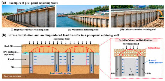
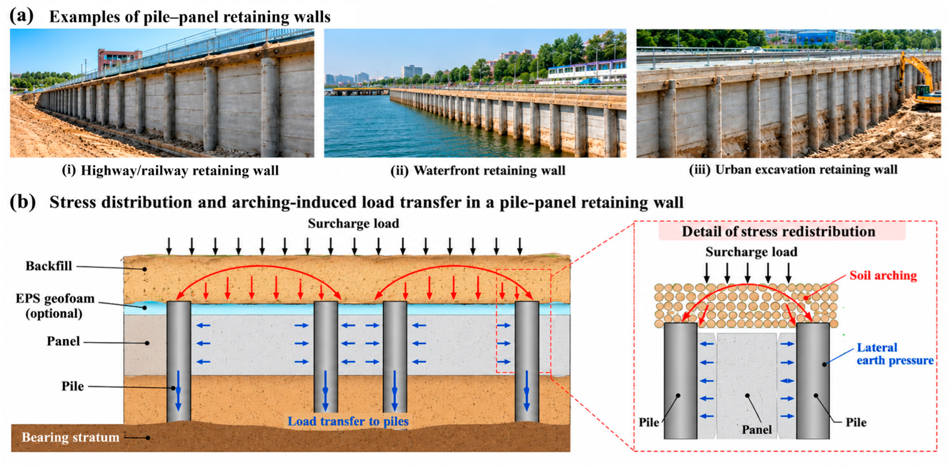
EPS geofoam can reduce lateral earth pressure when placed between the backfill and a retaining wall. Figure 1a shows typical applications of pile–panel retaining walls, while Figure 1b illustrates how soil arching transfers part of the load to the piles, reducing lateral pressure on the intervening panels.
Figure 1.
Examples of pile–panel retaining walls and the arching-induced load-transfer mechanism: (a) typical engineering applications and (b) schematic of stress redistribution and arching-induced load transfer.
Horvath [12,13] first demonstrated that interposing a low-density EPS panel between a rigid retaining wall and the fill can transform the lateral stress state from at-rest toward active conditions, as the compressive deformation of the EPS layer permits the fill to mobilize its shear strength. Subsequent experimental and numerical studies have systematically characterized the influence of EPS density and thickness on the magnitude of load reduction under both static and dynamic loading conditions [14,15,16,17,18]. Ertugrul and Trandafir [14] demonstrated through physical model tests and numerical analyses that low-stiffness EPS allows additional lateral deformation of the retained soil, thereby mobilizing a greater portion of its shear strength and reducing the lateral earth thrust acting on rigid nonyielding retaining walls. Gade and Dasaka [17] investigated the short- and long-term effects of EPS geofoam on surcharge-induced lateral earth pressures through 1 g model tests. Their results showed that the lateral thrust reduction under pseudo-long-term loading was 2.4–8.1% higher than that obtained from short-term tests, indicating that time-dependent compression of the geofoam can further influence lateral load transfer between the backfill and retaining wall. Building on these experimental foundations, semi-empirical and analytical methods have been proposed to predict the lateral earth pressure on rigid continuous retaining walls with EPS inclusions. Ni et al. [19] developed a displacement-dependent analytical framework relating EPS compression to the mobilized fill friction angle; Xie et al. [20] extended this approach to nonyielding walls with geofoam of varying stiffness, and Han et al. [21] proposed a semi-empirical formula calibrated against model test data for a range of EPS densities and thicknesses. More recently, Fan et al. [22] investigated EPS-backed retaining walls under limited surcharge loading, and Lin et al. [23] conducted field testing and numerical analysis of EPS inclusions behind a sheet pile wall supporting an expansive soil slope. However, without exception, these existing methods were developed for the continuous-wall configuration, in which the EPS layer spans the full wall width and the problem is effectively two-dimensional. None accounts for the discrete pile–panel geometry, and in particular, none considers the interaction between the inter-pile soil arching effect and the compressive response of the EPS layer. Direct application of existing methods to pile–panel systems would therefore neglect an additional load-transfer path and systematically overestimate the lateral earth pressure on the retaining panels.
To address this gap, the present study proposes a semi-empirical formula for estimating the lateral earth pressure on the retaining panels of pile–panel retaining walls equipped with EPS geofoam inclusions. The derivation explicitly couples two mechanisms that have hitherto been treated independently: the soil arching effect mobilized between adjacent stabilizing piles, which governs horizontal stress redistribution from the retaining panels to the pile elements; and the linear-elastic compressive response of the EPS layer, which defines the displacement boundary condition at the panel face and controls the degree of arching mobilization. Compared with the displacement-dependent approaches of Ni et al. [19] and Xie et al. [20] and the empirically calibrated formula of Han et al. [21], the proposed method does not require a priori knowledge of wall displacement; it relies solely on standard soil parameters and EPS material properties obtainable from routine laboratory tests, which offers a practical advantage for design applications. The proposed formula is validated against a total of 37 physical model tests covering a systematic range of pile spacing-to-width ratios, EPS elastic moduli, and EPS thicknesses. Parametric analyses are further conducted to quantify the influence of each design variable on load-reduction performance and to establish practical guidance for the optimal configuration of EPS-backed pile–panel retaining walls in slope engineering.
2. Lateral Earth Pressure Analysis of Pile–Panel Retaining Walls with EPS Geofoam
For a rigid nonyielding retaining panel with EPS geofoam placed against the backfill face, the panel displacement equals the compression of the EPS layer, and the wall–fill interface friction angle equals the EPS–soil friction angle. The lateral earth pressure–displacement relationship can therefore be used to predict earth pressure on rigid retaining panels backed by EPS geofoam of varying properties [20]. This section first reviews the displacement-dependent lateral earth pressure framework and then extends the lateral stress–strain relationship to derive a semi-empirical formula applicable to the discrete pile–panel system.
2.1. Displacement-Dependent Lateral Earth Pressure Framework
Chen et al. [24] proposed a functional relationship between the mobilized internal friction angle and the corresponding fill displacement, derived from lateral stress–strain relationships obtained in stress-path triaxial tests:
where and denote the mobilized internal friction angle of the backfill and the mobilized wall–soil interface friction angle, respectively; and are their respective initial values; and and are the corresponding increments mobilized by deformation. Here, s denotes the displacement of the backfill. and are obtained according to:
where and denote the ultimate and initial internal friction angles of the backfill, respectively, and is the increment in the mobilized internal friction angle. Similarly, and denote the ultimate and initial wall–soil interface friction angles, respectively, and is the corresponding increment in the interface friction angle. is the failure ratio of the backfill determined from triaxial tests, and is the dimensionless displacement-related parameter adopted.
According to Coulomb’s earth pressure theory, the lateral active earth pressure of a cohesionless fill retaining wall at any depth is:
where is the lateral active earth pressure at depth , is the unit weight of the backfill, and is the depth measured vertically from the backfill surface.
It should be noted that Rankine’s earth pressure coefficients characterize limiting lateral stresses under idealized conditions (smooth vertical wall; horizontal backfill with no surface loading). Under the general loading conditions and discrete pile–panel geometry considered herein, Rankine’s framework is not directly applicable. Furthermore, application of Equation (5) requires the wall displacement s to be known before the lateral pressure P can be computed, which is generally unavailable in practical design. The present study therefore abandons this displacement-dependent approach and instead develops a deformation-compatibility-based framework in Section 2.2 that does not require prior knowledge of wall displacement.
2.2. Semi-Empirical Earth Pressure Formula for the Pile–Panel Retaining Wall
The soil arching effect develops in the soil mass between adjacent stabilizing piles (hereafter referred to as the inter-pile soil mass) when it tends to displace under landslide thrust or overburden pressure. The piles restrain this movement, causing stress to be redistributed from the deforming inter-pile soil mass toward the piles and the surrounding stable ground through the developed arch. The piles restrain this movement, causing stress to redistribute from the displacing soil block to the piles and the surrounding stable medium through the mobilized arch. To develop a tractable analytical model, the following assumptions and their corresponding modeling treatments summarized in Table 1 are adopted:
Table 1.
Model assumption.
The low density of the EPS geofoam (approximately 6–10 kg/m3), compared with the backfill bulk density (approximately 1600 kg/m3), supports neglecting its self-weight relative to the backfill-induced loading. This simplification does not imply that EPS is mechanically inactive; its compressive response remains explicitly incorporated into the proposed formulation.
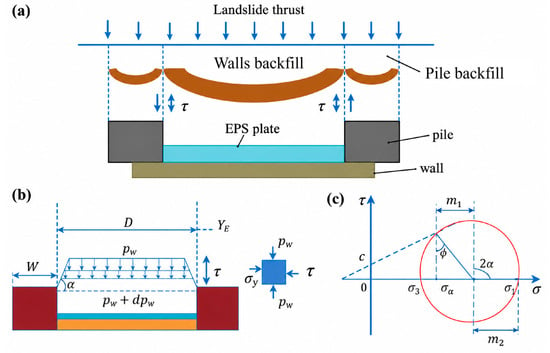
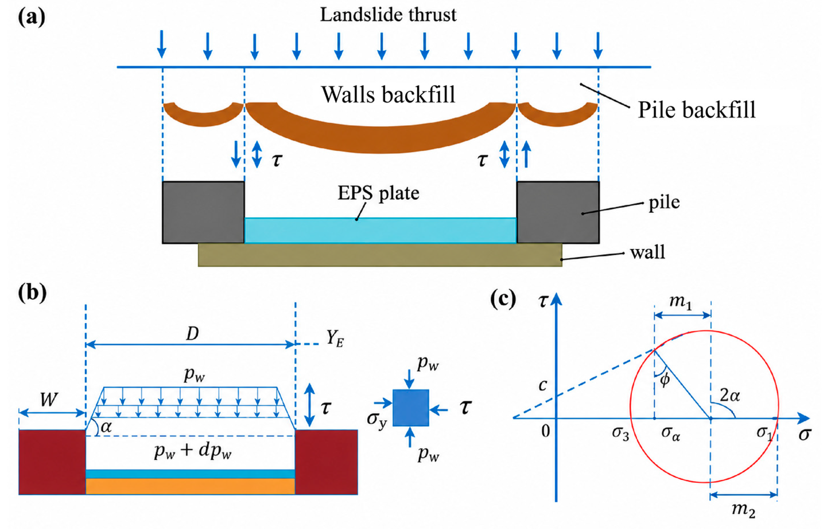
A plan view of the pile–panel retaining wall system is shown in Figure 2a, and the corresponding soil arch model is illustrated in Figure 2b.
Figure 2.
(a) Load-reducing pile sheet wall and calculation model of earth pressure; (b) calculation model of earth pressure behind sheet pile wall; and (c) fill stress circle on sliding surface behind wall.
Based on the limit equilibrium of the bulk fill, the assumed sliding surface extends from the pile face to a position YE behind the pile, where the differential settlement between the fill behind the pile and behind the retaining panel is zero. Mohr’s stress circle is constructed for the fill element on the sliding surface, as shown in Figure 2c, and the lateral earth pressure coefficient on the sliding surface is derived from the geometric relationships of Mohr’s stress circle.
For non-cohesive soil, c = 0, the lateral earth pressure coefficient v of the micro-element of the sliding surface of the sheet pile wall is defined:
According to the shear strength relationship of soil, the shear stress of the filling on the sliding surface is composed of the cohesion of the filling and the friction resistance of the backfill:
where c is the fill cohesion, is the shear stress, and is the horizontal earth pressure. In the case of retaining walls without displacement, the most commonly used method of calculating the earth pressure coefficient is Jaky’s [25] semi-empirical and semi-theoretical static earth pressure coefficient formula for coarse-grained soils.
Relationship between horizontal and vertical stresses:
where is the vertical earth pressure at depth h, given by ; is the uniformly distributed surcharge applied at the ground surface; and is the static earth pressure coefficient, given by .
Ma et al. [26] proposed that the evolution model of equal settlement soil arching can be applied to the calculation model of earth pressure on the sliding surface through the aluminum rod test. The inclination angle between the sliding surface and the horizontal direction is , and the sliding surface behind the wall is vertical. The filling on the sliding surface is just at the critical limit of the full play of the soil arching form for cohesionless soil (c = 0). Substituting the stress coefficient from Equation (6) and the horizontal stress from Equation (8) into the Mohr–Coulomb criterion in Equation (7) yields the shear stress mobilized along the assumed sliding surface:
Based on the above analysis, the calculation model of the force balance of the micro-element is established, as shown in Figure 3.
Figure 3.
Microcellular force model: (a) horizontal force equilibrium of EPS slab and (b) fill stress circle on sliding surface behind wall.
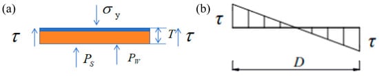
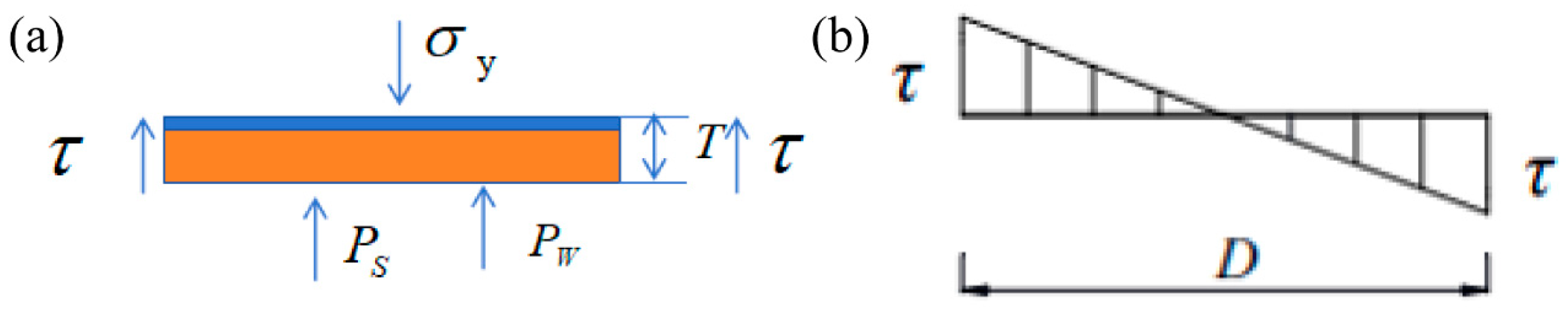
The horizontal stress equilibrium of the representative element shown in Figure 3a is expressed as Equation (10), accounting for the compressive resistance of the EPS layer, the residual lateral pressure acting on the retaining panel, and the shear contributions from the two sides of the element:
here, denotes the compressive stress mobilized by EPS deformation, is the lateral earth pressure acting on the retaining panel, and represents the shear stress acting at each side of the representative element.
Based on the assumption of small deformation and continuity of the fill behind the wall, the fill shear stress varies linearly in the horizontal direction and is minimum at the span of the retaining wall and maximum at the junction of the retaining wall and the pile, as shown in Figure 3b. For the sheet pile wall spacing D, the uneven displacement of the sheet pile wall should satisfy the following when the soil arch effect is fully exerted: when the shear stress of the fill on the sliding surface is fully exerted, the minimum shear strain of the fill on the sliding surface satisfies the relation:
where G is the shear modulus of the fill, Ed is the elastic modulus of the fill, is the Poisson’s ratio of the fill, is the shear strain when the shear stress of the fill behind the wall is in full play, and S is the uneven settlement of the fill.
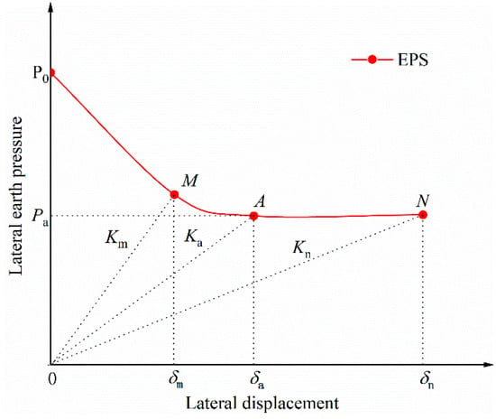
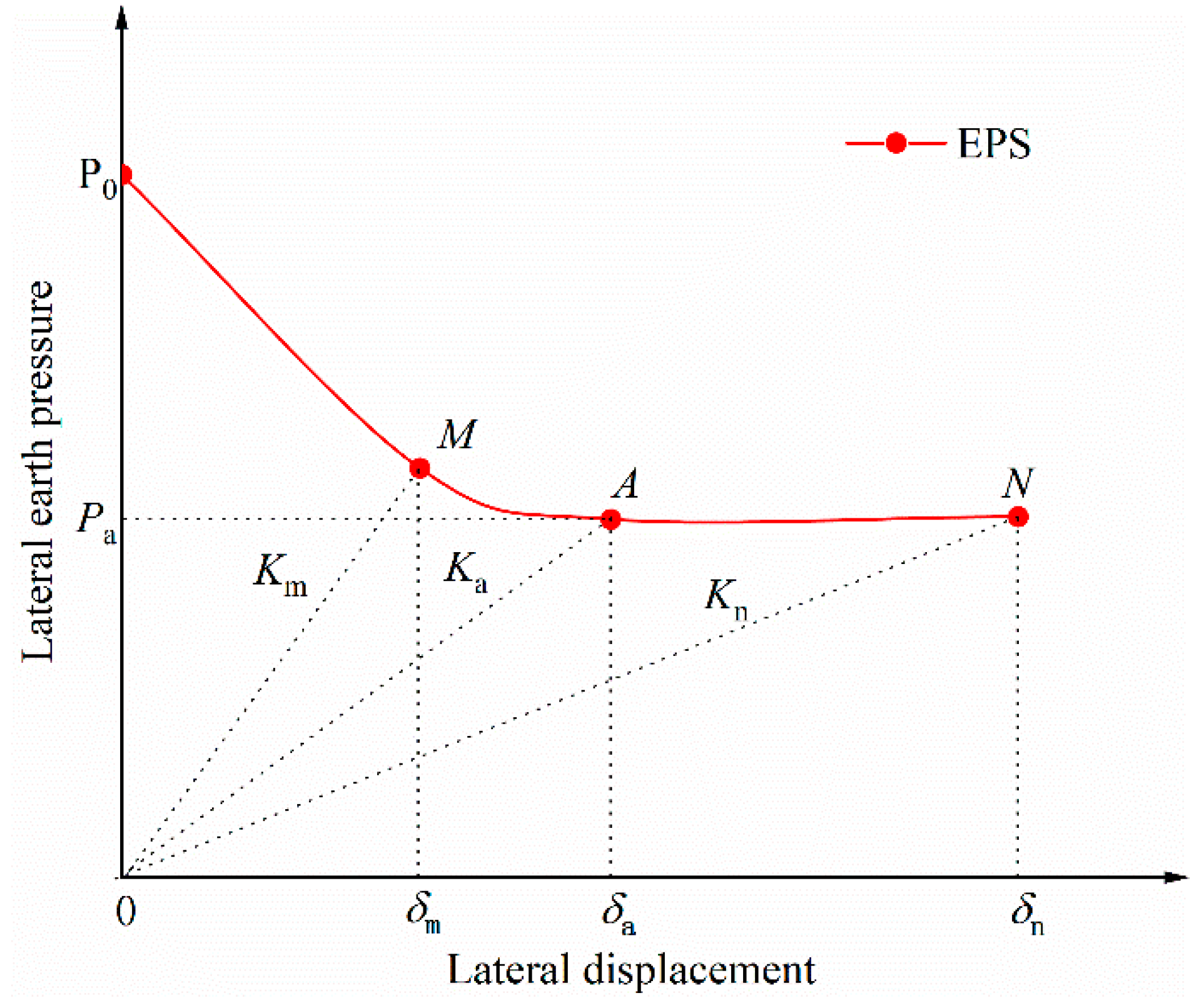
Ideally, the value of earth pressure acting on the back of the retaining wall is equal to the compressive stress of the EPS and the value of earth pressure transferred to the EPS by the fill, ignoring the friction between the EPS and the fill. The horizontal displacement of the fill is equal to the compression of the EPS, as shown in Figure 4.
Figure 4.
Reduction in the lateral earth pressure with lateral displacement.
For EPS material, the earth pressure and displacement are linear in the elastic range [21], according to Equation (14):
By substituting the above relationships into the horizontal force equilibrium equation, the final semi-empirical expression for the lateral earth pressure acting on the retaining panel is obtained as follows:
where is the elastic force generated by the compression of EPS and is the earth pressure behind the wall.
Equation (15) couples arching-induced stress redistribution with the linear-elastic compressive response of the EPS layer through a deformation-compatibility framework. It employs the at-rest lateral earth pressure coefficient and the sliding-surface micro-equilibrium condition to eliminate the need for a priori knowledge of wall–backfill displacement. Compared with the displacement-dependent approaches of Ni et al. [19] and Xie et al. [20], both developed for conventional continuous retaining walls, and the semi-empirical formula of Han et al. [21], Equation (15) is specifically formulated for discrete pile–panel systems in which the soil arching effect between piles governs lateral load transfer. Whereas the methods of Ni et al. [19] and Han et al. [21] require calibration from back-calculated or numerically fitted displacement parameters, Equation (15) requires only standard soil and EPS material properties obtainable from routine laboratory tests.
3. Validations by Model Tests
3.1. Test Equipment
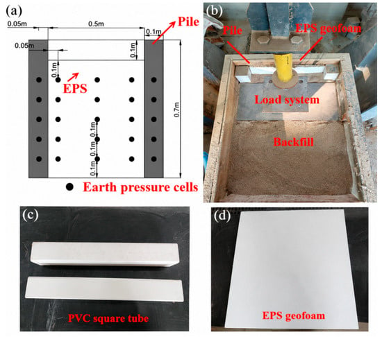
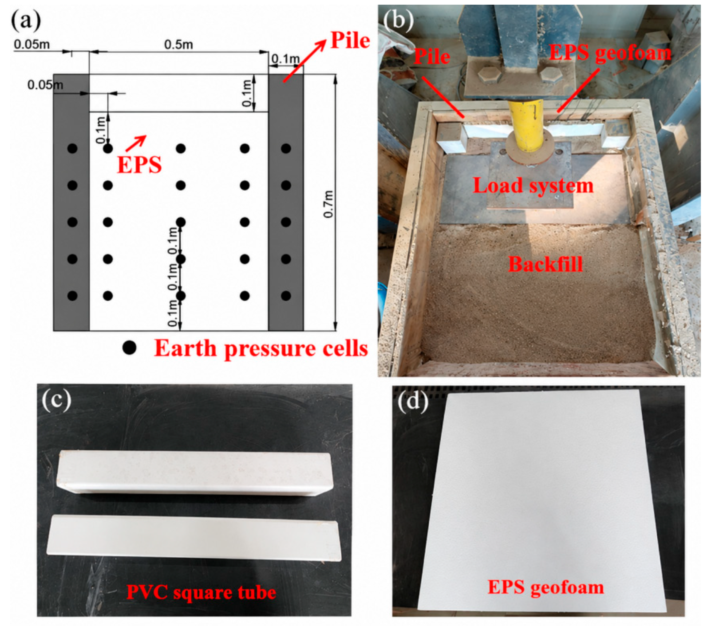
The model tests were carried out in a model box with internal dimensions of 1000 mm × 600 mm × 760 mm (length × width × height), as shown in Figure 5a. Three translucent tempered glass panels (10 mm thick) were installed on the front face to allow visual inspection during testing; the top face was left open. The side panels were constructed from 25 mm thick wooden planks. Model stabilizing piles were embedded in a sand foundation cast within the model box. Corner braces and sealant were applied to all seams to prevent distortion during loading and ensure the accuracy of the measurements. To reduce sidewall friction, a thin layer of lubricant was applied to the inner faces of the side panels prior to testing [27]. A servo-controlled hydraulic loading system with programmable loading rate and duration was used. To ensure uniform distribution of the applied vertical load and to prevent stress concentrations or localized penetration at the loading contact, a rigid steel loading plate (1000 mm × 500 mm × 10 mm) was positioned on top of the fill surface. Miniature earth pressure sensors (28 mm diameter; 0.6 MPa full-scale range, manufactured by Nanjing Danmo Electronic Technology Co., Ltd., Nanjing, China) were installed as shown in Figure 5b. Prior to testing, all sensors were calibrated by embedding them in soil at a controlled density and comparing readings against a reference pressure. Static strain data were acquired using a data logger connected to a personal computer for real-time visualization and storage.
Figure 5.
Diagram of test equipment: (a) test model diagram; (b) earth pressure gauge layout; (c) model piles; and (d) EPS geofoam.
3.2. Test Materials
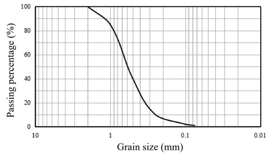
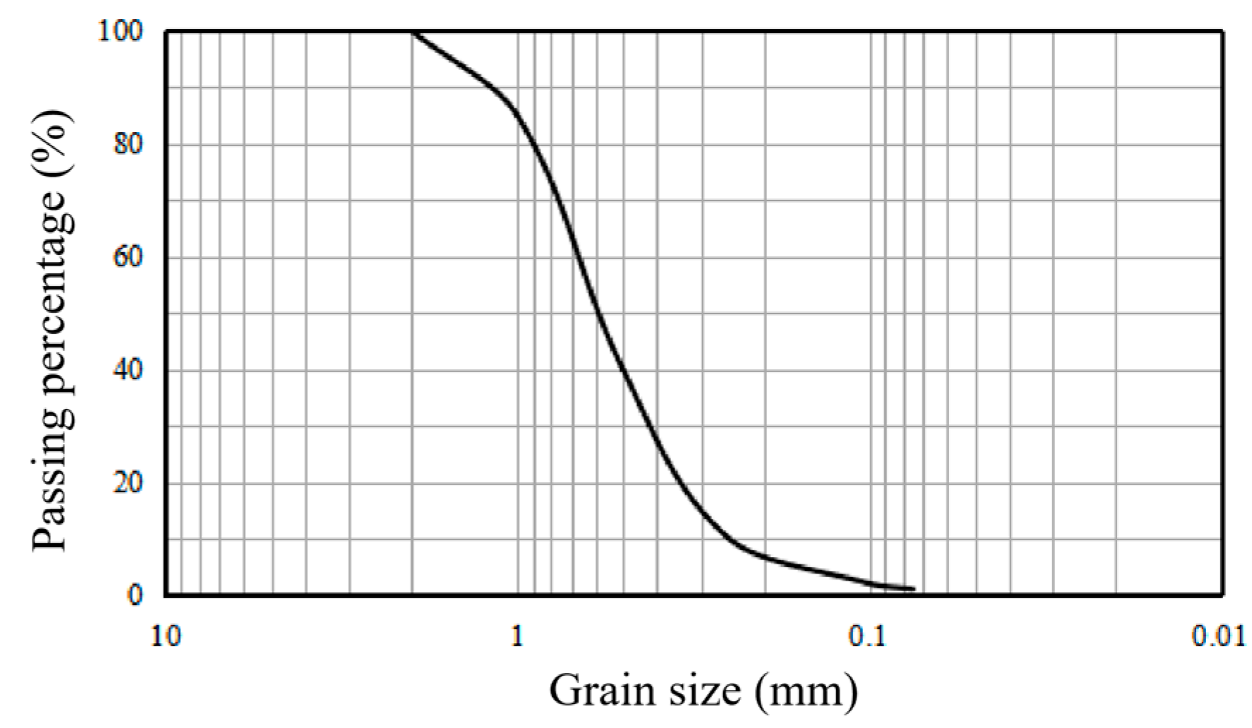
The backfill soil used in this test is dry sandy soil, which effectively reduces the influence of moisture on the test results. The filling adopts the filling method of inclusion paving and inclusion compaction. The soil properties were determined in accordance with the Chinese national standard GB/T 50123–2019, Standard for Geotechnical Testing Method [28]. The particle-size distribution of the dry sand was determined by sieve analysis, while the relevant density and direct shear tests were conducted in accordance with the corresponding procedures specified in the standard. The particle-size distribution curve is presented in Figure 6, and the measured physical properties are summarized in Table 2.
Figure 6.
Soil particle grading curve.
Table 2.
Basic fundamental physical parameters of the test sandy soil.
A PVC square tube with dimensions of 100 mm × 100 mm × 700 mm (simulated pile) was used for the test; see Figure 5c. To prevent sand from squeezing into the tube during the test, transparent tape was used to seal the mouth of the tube at both ends. The parameters of the piles are listed in Table 3. The EPS thickness levels were T1 = 30 mm, T2 = 40 mm, and T3 = 50 mm.
Table 3.
Material parameters of the PVC pile and the EPS
The EPS geofoam was used for the test as shown in Figure 5d. Since low-density EPS geofoam is prone to rupture and poor durability, experience has shown that the minimum value of EPS density is taken as 6 kg/m3 [13]. In this study, to obtain the elastic modulus of higher-density EPS, an approximation of E was obtained by fitting the test data of EPS at 2% compressive strain [16]. The parameters of the EPS geofoam are included in Table 3; the EPS elastic modulus levels were E1 = 0.70 MPa, E2 = 1.18 MPa, and E3 = 1.63 MPa.
3.3. Testing Procedures
A hydraulic jack with a rated capacity of 50 kN and a maximum stroke of 150 mm was used to apply the load. A five-stage incremental loading protocol was adopted, with a load increment of 10 kN at each stage. Each load level was maintained for at least 30 min, and the subsequent load increment was applied only after the measured responses had stabilized. Although manual control may have introduced minor variations in the loading rate, these variations were expected to have a limited influence on the final soil-stress distribution under the quasi-static loading conditions considered in this study [29].
The model tests were designed primarily to investigate the effects of pile spacing and EPS geofoam properties on lateral earth pressure under consistent experimental conditions. Complete similitude between the model and a full-scale prototype was not imposed for all soil and structural parameters. The scale factors adopted in the present study are summarized in Table 4, where Cl, Cd, Cμ, and Cσ denote the scale factors for length, density, displacement, and stress, respectively. Strict material similitude for the PVC structural components was not enforced. Consequently, the experimental results are primarily used to compare the relative responses of different configurations within the tested model-scale range. Extrapolation of the measured responses to full-scale engineering applications should therefore be undertaken with caution.
Table 4.
Scale dimensions of the model test.
3.4. Testing Conditions
The objective was to study the accuracy of the formula proposed in this paper and the influence of different factors on the earth pressure behind the sheet pile wall. A total of 37 test conditions were considered to investigate the effects of pile spacing and EPS geofoam properties. One reference case (G1) was established without piles. The remaining 36 cases considered four pile-spacing-to-pile-width ratios (D/W = 2, 3, 4, and 5), three EPS geofoam elastic moduli E1, E2, and E3, and three EPS thicknesses T1, T2, and T3. For each (D/W) ratio, all nine combinations of elastic modulus and thickness were considered. Including the reference case, the total number of test conditions was 37. The complete test matrix is presented in Table 5.
Table 5.
Test conditions.
3.5. Validation of the Semi-Empirical Model
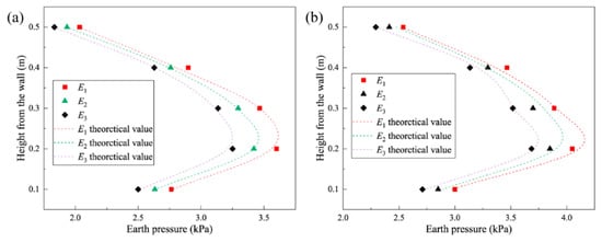
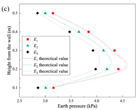
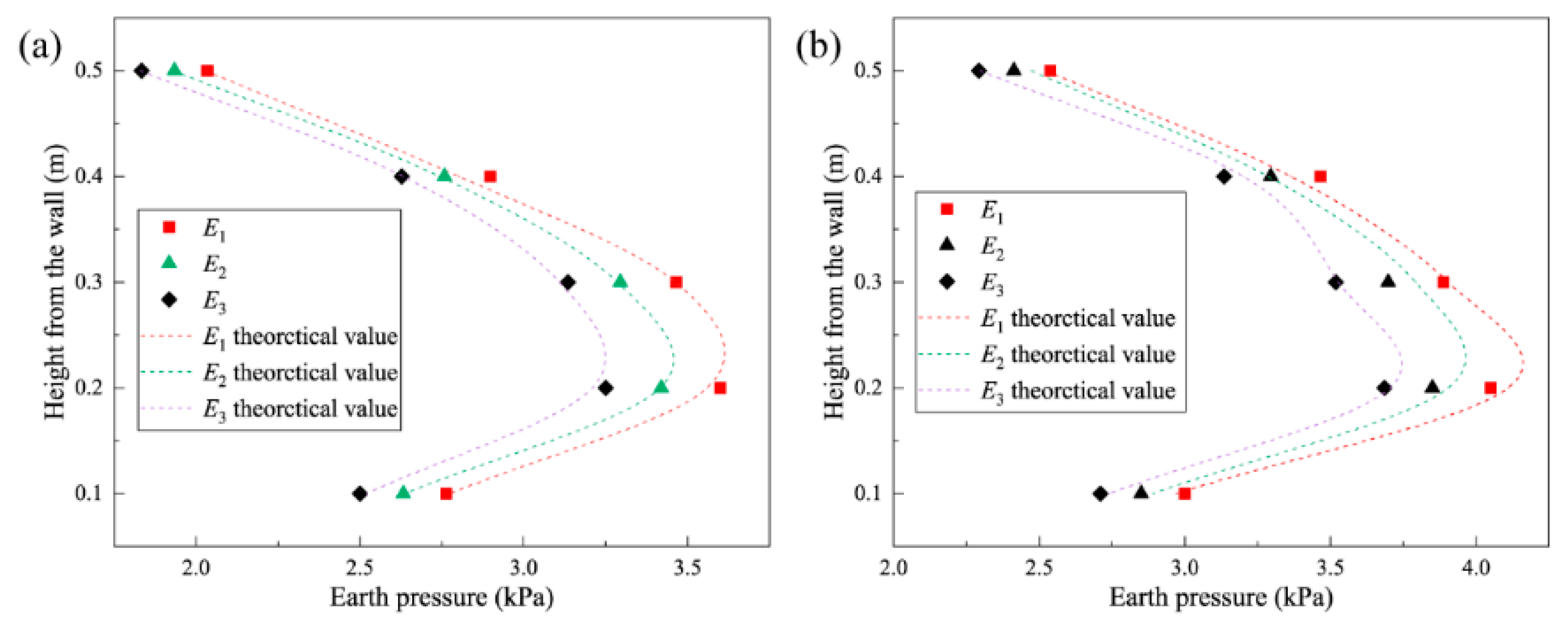
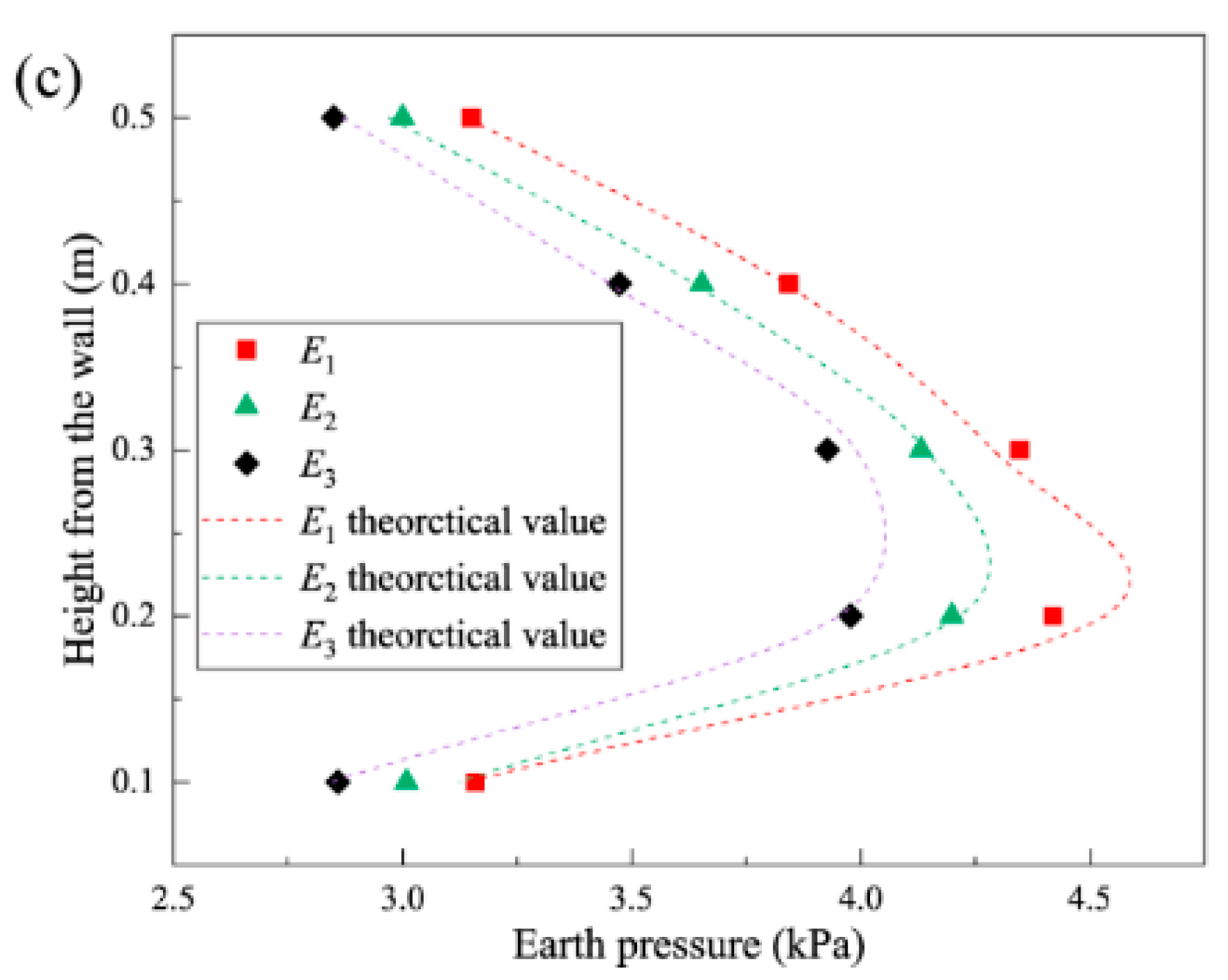
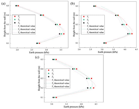
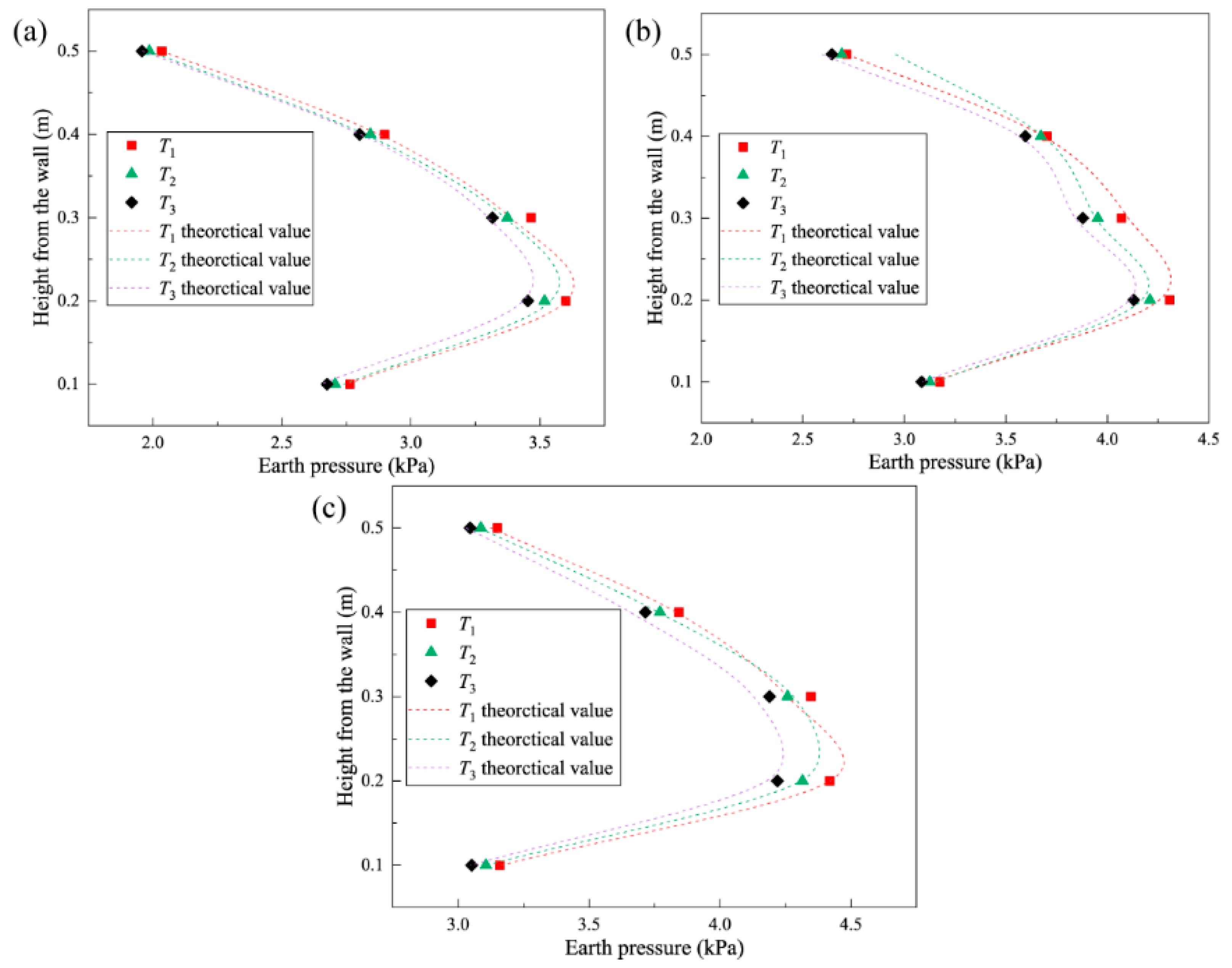
To check the accuracy of the theoretical formulas, the sheet pile wall model with D/W = 5 was selected, and EPS geofoam with both thicknesses of 3 cm and different moduli of elasticity was laid behind the wall, and Figure 7 depicts the variation in the experimental and theoretical values of the soil pressure behind the wall with the modulus of elasticity of the EPS boards. The results show that the theoretical and experimental values of soil pressure behind the wall are the same, and the theoretical value of soil pressure behind the wall exhibits a slightly larger value than the experimental value in the middle and lower part of the wall, and this result may be the influence of the model test boundary effect, which will cause the soil pressure to decrease within about a quarter of the height of the bottom.
Figure 7.
Model test and theoretical lateral earth pressures on sheet pile wall with different EPS elastic moduli: (a) q = 30 kN; (b) q = 40 kN; and (c) q = 50 kN.
Three different thicknesses of EPS geofoam with modulus of elasticity E1 were laid behind the wall to investigate the accuracy of the theoretical equation and the effect of changing the thickness of EPS on the earth pressure behind the wall. Figure 8 shows the theoretical and experimental values of earth pressure distribution along the wall height, and it can be found that the theoretical and experimental values of earth pressure at different heights show general consistency. The comparison between the theoretical predictions and experimental measurements indicates that Equation (15) can reasonably estimate the lateral earth pressure acting on the retaining panels of pile–panel retaining walls incorporating EPS geofoam under the investigated conditions.
Figure 8.
Model test and theoretical lateral earth pressures on sheet pile wall with different EPS thicknesses: (a) q = 30 kN; (b) q = 40 kN; and (c) q = 50 kN.
4. Parameter Analysis and Discussion
4.1. Effect of Stabilizing Piles on Earth Pressure
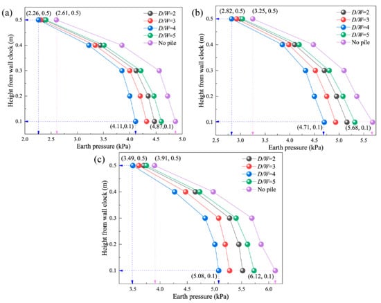
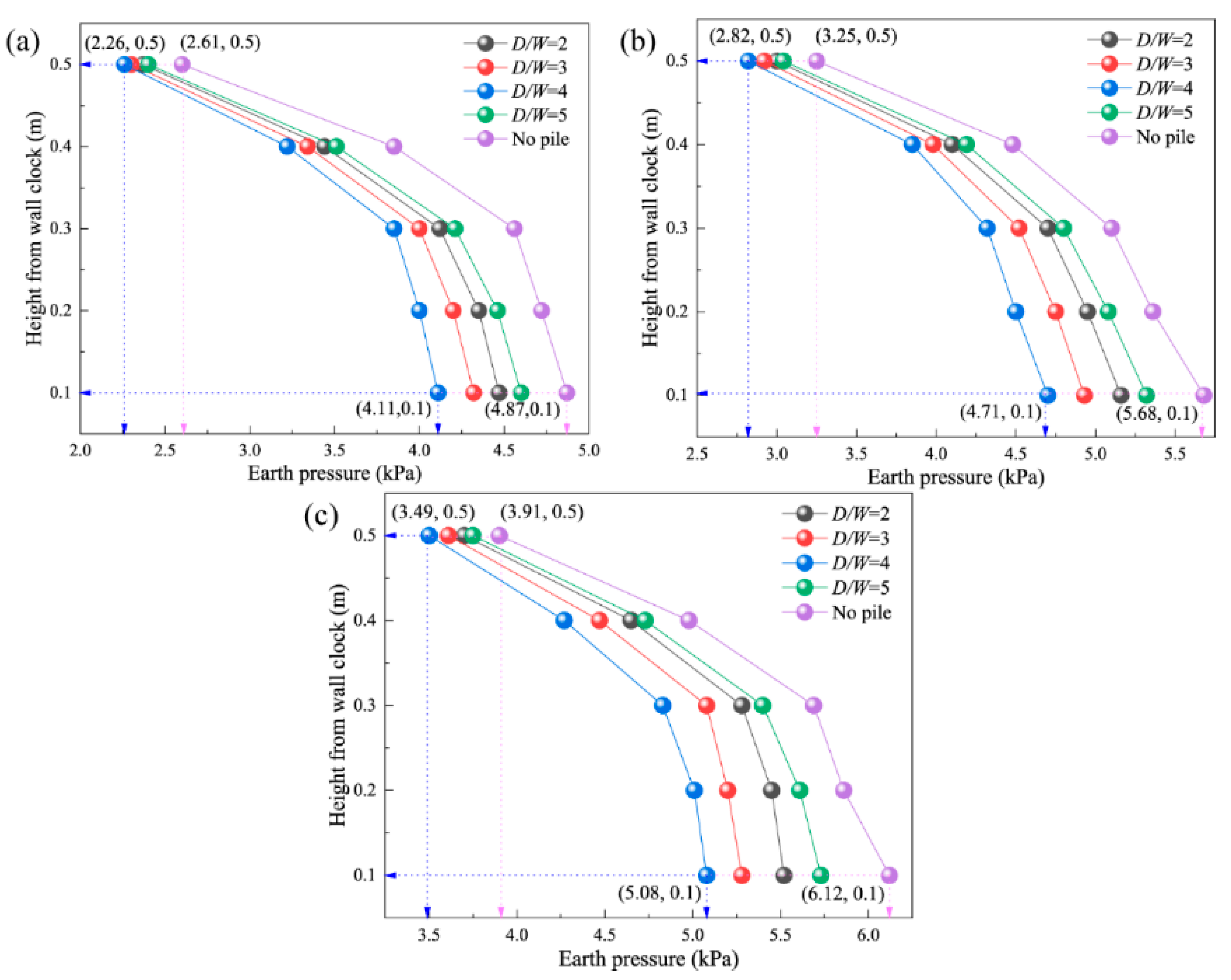
In this section, lateral horizontal earth pressures of sheet pile walls with different pile spacing are discussed by varying the spacing of the piles. A comparative analysis with the retaining wall without piles is shown in Figure 9.
Figure 9.
Effect of pile spacing on earth pressure behind the wall: (a) q = 30 kN; (b) q = 40 kN; and (c) q = 50 kN.
The pile spacing exerts a significant influence on the lateral earth pressure distribution. The pile–panel retaining wall consistently produces lower earth pressures than the no-pile retaining wall, demonstrating the load-reduction benefit of the pile–panel configuration. As fill depth increases, the earth pressure profile steepens progressively, indicating that the soil arching effect has distinct spatial characteristics: arching is stronger in the middle and lower portions of the fill and intensifies with depth but diminishes in the vicinity of the wall face. This spatial variation likely reflects the dominant influence of the applied surface load on the shallow fill layers, with its effect attenuating with depth.
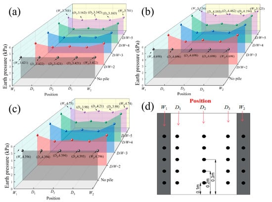
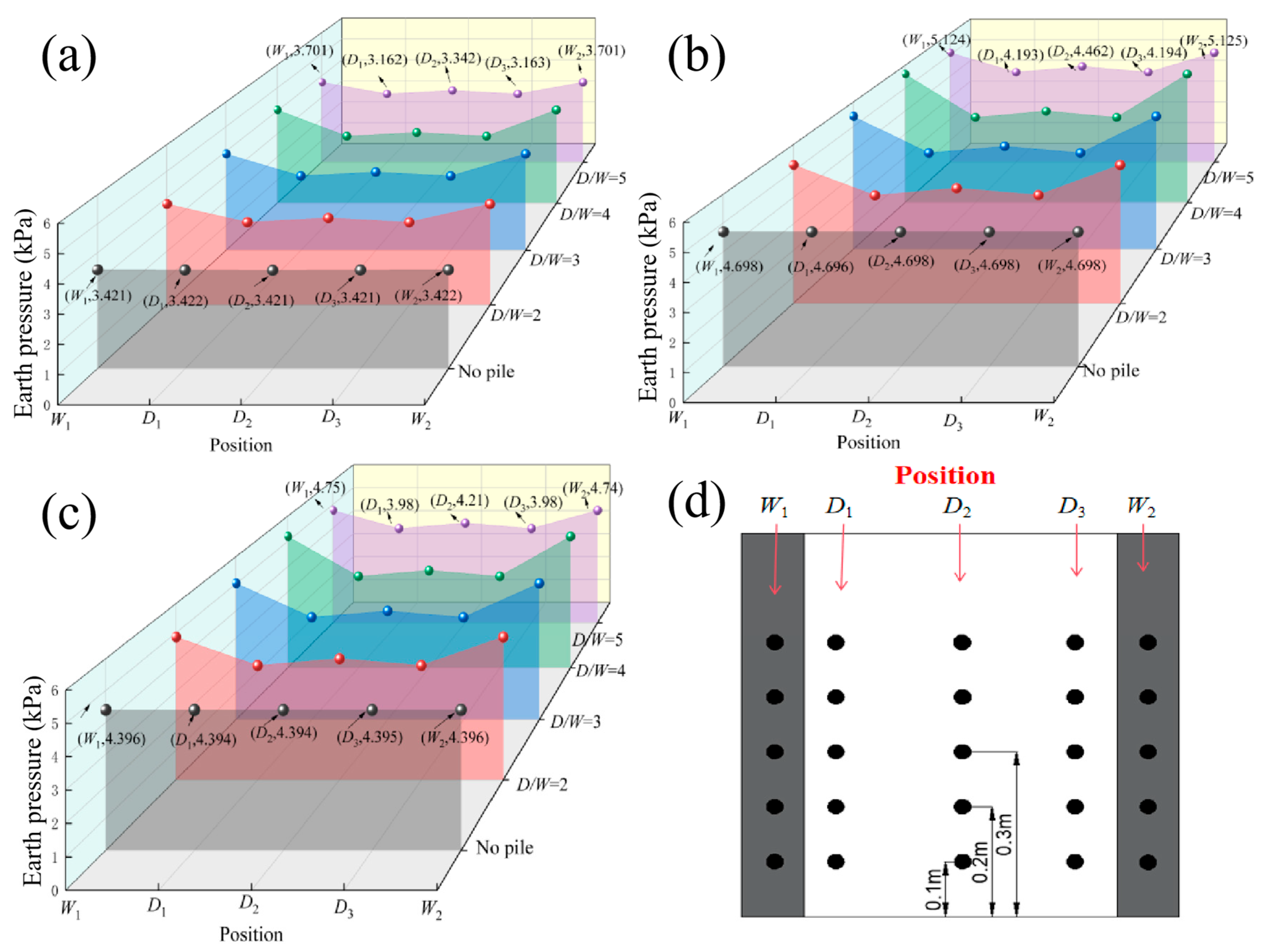
To further characterize the distribution of soil arching between the piles, horizontal earth pressure profiles were examined at three heights from the wall base: 0.30 m, 0.20 m, and 0.10 m, as shown in Figure 10. In Figure 10, W1 and W2 denote the earth pressures measured directly behind the pile faces; D1, D2, and D3 denote mid-span earth pressures at three positions along the wall, with the outermost sensor placed 50 mm from the pile face to avoid local stress concentration. The subsequent analysis is performed at a reference surface load of 50 kN, since this level ensures model stability across all test conditions.
Figure 10.
Effect of pile spacing on horizontal earth pressure: (a) height from wall base 0.3 m; (b) height from wall base 0.2 m; (c) height from wall base 0.1 m; and (d) position.
For the no-pile retaining wall (G1), the lateral earth pressure remains nearly uniform at a given height. By contrast, the pile–panel retaining wall shows pronounced horizontal variation at the same height: the earth pressure is lowest at the mid-span of the retaining panel and highest at the pile face. This stress concentration at the pile back is characteristic of the soil arching effect—as the fill between piles displaces laterally, the stress is transferred to the piles, and the retaining panel receives only the residual arch thrust. The load-reduction effect of the pile–panel system is therefore primarily a consequence of this stress transfer.
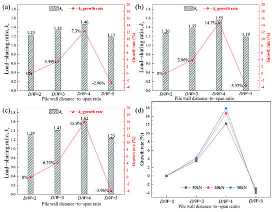
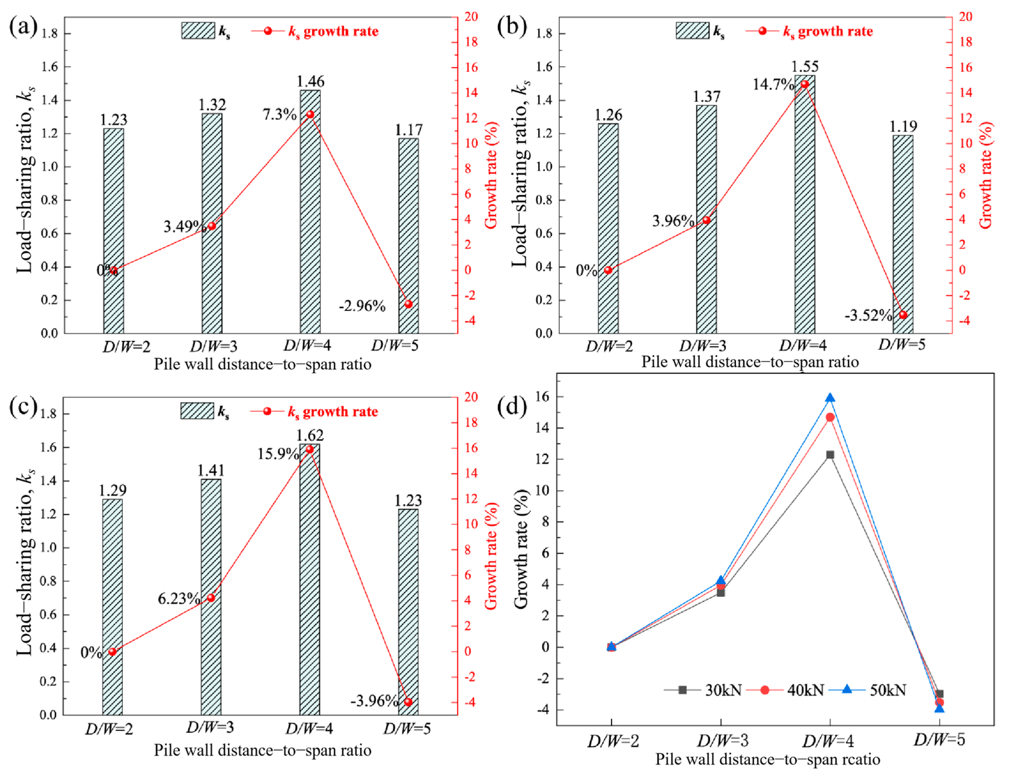
Since the soil arch effect occurs essentially as a transfer of stress in the soil, to further illustrate the distribution law of the soil arch effect between piles and the earth pressure on the pile slab, it is assumed that the earth pressure acting on the pile sheet wall is uniformly distributed along the horizontal direction. The ratio of the average value of earth pressure on the back of the pile to the average value of earth pressure on the back of the plate is noted as ks, and the growth rate is determined by the relative growth rate Q, and it is calculated by Equation (16):
where ks0 is for pile spacing and pile width ratio ks, ks1 is for pile spacing and pile width ratio of 1:2 ks. The formula for ks is:
where pp is the average value of earth pressure behind the pile, and pb is the average value of earth pressure behind the wall. The value of ks can reflect the strength of the soil arch effect. The larger the ks value is, the more the horizontal earth pressure behind the wall of the pile slab wall is transferred to the back of the pile due to the soil arching effect of the fill behind the wall, and the soil arching effect of the fill behind the wall of the pile slab wall is more obvious at this time, and vice versa.
Figure 11 shows that the load-sharing ratio ks first increases and then decreases with increasing pile spacing-to-width ratio (D/W). The relative growth rate of ks reaches a maximum of 15.9% at (D/W = 4), indicating that this configuration provides the most effective load sharing among the tested cases. At smaller spacing ratios, the development of inter-pile soil arching and the associated stress redistribution are relatively limited. As D/W increases, the soil arching mechanism becomes more effectively mobilized, promoting the transfer of lateral stress from the retaining panels toward the stabilizing piles. However, when the spacing increases beyond (D/W = 4), the arching interaction becomes less effective, and the load-sharing ratio decreases. At (D/W = 5), the lateral earth pressure acting on the retaining panels approaches that of the reference configuration without piles, indicating that the load-sharing benefit is substantially reduced at the largest spacing investigated. These results demonstrate that pile spacing plays an important role in controlling inter-pile soil arching and lateral load redistribution.
Figure 11.
Effect of pile spacing on load-sharing ratio: (a) q = 30 kN; (b) q = 40 kN; (c) q = 50 kN; and (d) comparison of growth rates under different loads.
When the pile spacing and pile width ratio reach 5, the difference between the values of the earth pressure behind the wall and the retaining wall without the pile is small. It can be concluded that when the pile spacing and pile width ratio exceed 5, the soil arching effect of the sheet pile walls gradually disappears and cannot support a sufficient arching angle, thus losing the effect of load shearing.
4.2. Analysis of the Influence of Elastic Modulus of EPS Geofoam
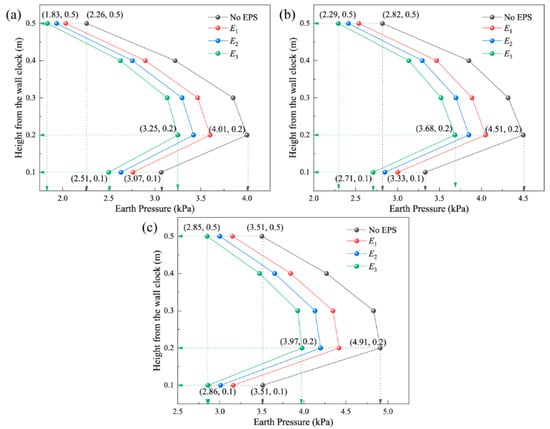
This section examines the effect of EPS elastic modulus on lateral earth pressure behind the retaining panel, with EPS thickness fixed at T1 = 30 mm to isolate the modulus effect from thickness interference.
As shown in Figure 12, placing EPS geofoam behind the panel substantially reduces lateral earth pressure compared with the no-EPS baseline. As surface load increases, the earth pressure increment peaks near the wall top, forming a distribution that first rises then falls with depth. This pattern aligns with the numerical findings of Ertugrul and Trandafir [14]: EPS deformation concentrates in the high-stress lower wall section, and the resulting non-uniform compression modifies the earth pressure profile along wall height.
Figure 12.
Effect of EPS elastic modulus on earth pressure behind the wall: (a) q = 30 kN; (b) q = 40 kN; and (c) q = 50 kN.
At a fixed pile spacing, reducing the elastic modulus of the EPS consistently reduces the earth pressure behind the retaining panel. The mechanism is as follows: a lower elastic modulus increases the compressibility of the EPS layer, allowing the backfill to undergo greater horizontal displacement under the same load. This additional displacement mobilizes a higher degree of shear stress in the fill and promotes stress transfer from the fill to the piles via soil arching, reducing the net earth pressure on the retaining panel. This mechanism is consistent with the soil arching interpretation established in Section 4.1.
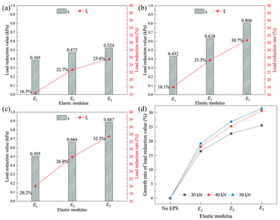
As shown in Figure 13, to better characterize the effect of EPS parameters on the earth pressure behind the wall, this paper defines the value of load reduction and load reduction ratio , where p0 is the combined earth pressure behind the wall without piles and EPS flexible geofoam. pn is the combined earth pressure behind the wall with EPS geofoam and piles laid behind the wall for different working conditions.
Figure 13.
Load reduction effect of EPS geofoam with different elastic moduli: (a) q = 30 kN; (b) q = 40 kN; (c) q = 50 kN; and (d) comparison of load reduction under different loads.
In the case of certain pile spacing, the addition of EPS geofoam can significantly reduce the earth pressure behind the wall, and as the elastic modulus of the EPS geofoam decreases, the earth pressure behind the wall also decreases gradually, and the load reduction value reaches the minimum value at E3. When the applied load is 50 kN and the pile spacing is 1:4, the thickness of the flexible geofoam inclusion is T1, the elastic modulus changes from E1 to E3, and the load reduction rate increases from 16.5% to 27.6%. Observation of the load reduction rate curve can be found; the slope of the curve of the load reduction rate first increases significantly and then gradually tends to be flat.
It should be noted that the absolute load-reduction values shown in Figure 13 are relatively small, which is associated with the relatively low earth pressures measured under the loading levels adopted in the present model tests. Nevertheless, the load-reduction ratio provides a normalized measure of the relative reduction compared with the reference condition, enabling the effects of different EPS elastic moduli to be compared under consistent loading conditions. Therefore, the absolute load-reduction value and the load-reduction ratio should be interpreted together. The results presented here primarily characterize the relative influence of EPS elastic modulus under the investigated model test conditions. Xie et al. [20] reported a comparable result from model tests on nonyielding retaining walls, finding that EPS with a density of 12 kg/m3 reduced earth pressure to approximately 85% of the value measured for 24 kg/m3 EPS; the present results extend this finding to the pile–panel configuration.
4.3. Analysis of the Influence of EPS Geofoam Thickness
In this section, the effect of EPS thickness on the lateral earth pressure behind the retaining panel is examined. The analysis is conducted at a fixed EPS elastic modulus of E1 = 0.7 MPa, so that thickness is the only variable; this isolates the thickness effect from the elastic modulus effect. Three thicknesses are considered: T1 = 30 mm, T2 = 40 mm, and T3 = 50 mm.
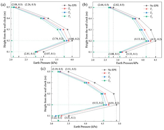
Figure 14 shows the earth pressure distributions along the wall height. Under the same surface load level, greater EPS thickness consistently produces lower earth pressure behind the retaining panel. The mechanism is analogous to that of reduced elastic modulus: a thicker EPS layer can accommodate a greater total compression before reaching its elastic limit, which allows the backfill to sustain larger horizontal displacements. These larger displacements promote fuller mobilization of shear stress in the fill and enhance stress transfer to the piles, thereby reducing the residual earth pressure on the retaining panel.
Figure 14.
Effect of EPS thickness on earth pressure behind the wall; (a) q = 30 kN; (b) q = 40 kN; (c) q = 50 kN.
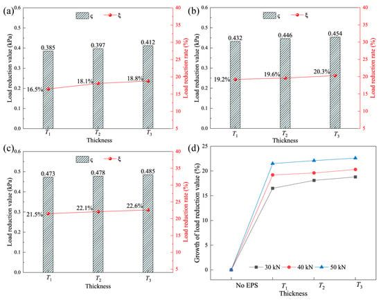
As shown in Figure 15, it is found that with the increase in EPS geofoam thickness, the load reduction rate increases, and the distance of the overall upward shift of the load reduction rate curve decreases and gradually tends to be gentle with the increase in thickness. Through the model test of the retaining wall, it is found that the earth pressure behind the wall decreases significantly with the initial increase in the thickness of the geofoam, while the earth pressure decreases more gently with the further increase in the thickness. At the same stress level, the thicker EPS geofoam has stronger compressibility and a more significant reduction in earth pressure. According to the analysis of the reasons, the deformation of soil is limited under certain loads, which has a similar effect on the EPS geofoam, and the role of the geofoam in coordinating deformation and energy absorption is no longer significant. Unless the load value is further increased, the soil will undergo greater deformation. At this time, the geofoam with a thicker and smaller elastic modulus can absorb more displacement to better play the role of decompression.
Figure 15.
Load reduction effect of different thicknesses of EPS geofoam: (a) q = 30 kN; (b) q = 40 kN; (c) q = 50 kN; and (d) comparison of load reduction under different loads.
In practice, the normal load of the retaining wall is generally in a relatively stable range, so the geofoam with medium thickness can be employed to play a better role in load reduction.
5. Discussion
The load-transfer performance of pile–panel retaining walls is strongly influenced by pile spacing. The load-sharing ratio ks first increases and then decreases with increasing D/W, reaching a maximum relative growth rate of 15.9% at (D/W = 4). This trend reflects the balance between inter-pile soil deformation and arching-induced stress redistribution. At D/W = 5, the earth pressure approaches that of the wall without piles, indicating a weakened load-transfer effect. Thus, D/W = 4 is the most favorable configuration among the cases investigated.
EPS compressibility further influences lateral earth pressure by accommodating backfill displacement. At D/W = 4 and q = 50 kN, the load-reduction ratio increases from 16.5% to 27.6% as the EPS elastic modulus decreases from E3 = 1.63 MPa to E1 = 0.70 MPa at a fixed thickness of 30 mm. Increasing EPS thickness from 30 to 50 mm also enhances load reduction, although the incremental benefit becomes less pronounced. These results highlight the importance of EPS deformation capacity in facilitating stress redistribution. Absolute load reduction and reduction ratio should be interpreted separately, as a high relative reduction does not necessarily indicate a large pressure difference.
The proposed formulation extends existing methods for continuous retaining walls by incorporating inter-pile soil arching and EPS compressibility within a deformation-compatibility framework. The agreement between predicted and measured earth-pressure distributions supports its applicability under the investigated conditions, although discrepancies remain in some wall regions. The validation is limited to model-scale tests using dry cohesionless sand under static loading. Further investigation involving different soil conditions, stress levels, and prototype structures is required to establish the method’s broader applicability.
6. Conclusions
This study developed a semi-empirical method for predicting lateral earth pressure on the retaining panels of pile–panel retaining walls incorporating EPS geofoam. The method integrates inter-pile soil arching and EPS compressibility within a deformation-compatibility framework. The main conclusions are as follows:
- (1)
- The proposed method accounts for arching-induced stress redistribution and the compressive response of EPS without requiring prior knowledge of wall–backfill relative displacement. The model test matrix comprised one reference configuration without piles and 36 combinations of pile spacing, EPS elastic modulus, and thickness. Comparisons between theoretical predictions and experimental measurements showed general agreement in lateral earth-pressure distributions, supporting the applicability of the method under the investigated conditions.
- (2)
- Pile spacing significantly affected the load-sharing behavior. As the pile spacing-to-width ratio increased from 2 to 4, the load-sharing ratio ks increased, with its maximum relative growth rate reaching 15.9% at D/W = 4. At D/W = 5, the earth pressure on the retaining panels approached that of the reference configuration without piles, indicating a diminished load-transfer benefit. Thus, D/W = 4 provided the most favorable load-sharing performance among the configurations investigated.
- (3)
- Within the investigated ranges of EPS elastic modulus and thickness, decreasing the modulus and increasing the thickness reduced the lateral earth pressure on the retaining panels. At D/W = 4, q = 50 kN, and a fixed EPS thickness of 30 mm, the load-reduction ratio increased from 16.5% to 27.6% as the modulus decreased from 1.63 to 0.70 MPa. The incremental benefit of increasing EPS thickness became less pronounced within the tested range.
The findings are based on model-scale tests using dry cohesionless sand under static loading. Further validation under different soil conditions and representative prototype stress levels is necessary before the proposed method can be generalized to field applications.
Author Contributions
All authors contributed to the study conception and design. The experiments were performed by Q.M., A.L., J.L. and H.S. Material preparation, data collection and analysis were performed by Q.M., A.L., J.L. and H.S. The first draft of the manuscript was written by Q.M., A.L., J.L. and H.S. and all authors commented on previous versions of the manuscript. All authors have read and agreed to the published version of the manuscript.
Funding
This research was funded by the National Natural Science Foundation of China (No. 52078194), the National Young Top-notch Talent of the “Ten Thousand Talents Program”, the Science Fund for Distinguished Young Scholars of Hubei Province (2022CFA043), the Young Top-notch Talent Cultivation Program of Hubei Province, the Outstanding Young and Middle-Aged Science and Technology Innovation Team of colleges and universities in Hubei Province (No. T2022010), the Innovation Demonstration Base of Ecological Environment Geotechnical and Ecological Restoration of Rivers and Lakes (No. 2020EJB004), and the Open Project Funding of the Key Laboratory of Intelligent Health Perception and Ecological Restoration of Rivers and Lakes, Ministry of Education, Hubei University of Technology (HGKFYB24).
Data Availability Statement
Data Availability Statements are required for all articles that are published with MDPI. During the peer review and editorial decision process, authors can be asked to share existing datasets or raw data that have been analyzed in the manuscript, and may be asked to indicate whether they will be made available to other researchers following publication. The authors will also be asked for the details of any existing datasets that have been analyzed in the manuscript.
Conflicts of Interest
The authors declare no conflicts of interest.
References
- Li, C.; Yan, J.; Wu, J.; Lei, G.; Wang, L.; Zhang, Y. Determination of the embedded length of stabilizing piles in colluvial landslides with upper hard and lower weak bedrock based on the deformation control principle. Bull. Eng. Geol. Environ. 2019, 78, 1189–1208. [Google Scholar] [CrossRef] [Scilit]
- Zhang, Y.; Hu, X.; Tannant, D.D.; Zhang, G.; Tan, F. Field monitoring and deformation characteristics of a landslide with piles in the Three Gorges Reservoir area. Landslides 2018, 15, 581–592. [Google Scholar] [CrossRef] [Scilit]
- Xiao, S.; Zeng, J.; Yan, Y. A rational layout of double-row stabilizing piles for large-scale landslide control. Bull. Eng. Geol. Environ. 2017, 76, 309–321. [Google Scholar] [CrossRef] [Scilit]
- Bartz, J.R.; Martin, C.D.; Hendry, M.T. Design procedure for landslide stabilization using sheet pile ribs. Can. Geotech. J. 2019, 56, 514–525. [Google Scholar] [CrossRef] [Scilit]
- Pirone, M.; Urciuoli, G. Analysis of slope-stabilising piles with the shear strength reduction technique. Comput. Geotech. 2018, 102, 238–251. [Google Scholar] [CrossRef] [Scilit]
- Chen, C.Y.; Martin, G.R. Soil–structure interaction for landslide stabilizing piles. Comput. Geotech. 2002, 29, 363–386. [Google Scholar] [CrossRef] [Scilit]
- Lai, H.J.; Zheng, J.J.; Zhang, R.J.; Cui, M.J. Classification and characteristics of soil arching structures in pile-supported embankments. Comput. Geotech. 2018, 98, 153–171. [Google Scholar] [CrossRef] [Scilit]
- Wu, J.; Li, C.; Liu, Q.; Fan, F. Optimal isosceles trapezoid cross section of laterally loaded piles based on friction soil arching. KSCE J. Civ. Eng. 2017, 21, 2655–2664. [Google Scholar] [CrossRef] [Scilit]
- Zhao, X.; Li, K.; Xiao, D. A simplified method to analyze the load on composite retaining structures based on a novel soil arch model. Bull. Eng. Geol. Environ. 2020, 79, 3483–3496. [Google Scholar] [CrossRef] [Scilit]
- Qin, C.B.; Chian, S.C.; Wang, C.Y. Kinematic analysis of pile behavior for improvement of slope stability in fractured and saturated Hoek–Brown rock masses. Int. J. Numer. Anal. Methods Geomech. 2017, 41, 803–827. [Google Scholar] [CrossRef] [Scilit]
- Bao, N.; Chen, J.; Wang, G.; Sun, R.; Yan, K. Analytical prediction of displacement-dependent lateral earth pressure against stabilizing piles in sandy slopes considering arching effect. Comput. Geotech. 2024, 176, 106776. [Google Scholar] [CrossRef] [Scilit]
- Horvath, J.S. Using geosynthetics to reduce earth loads on rigid retaining structures. In Proceedings of the Geosynthetics ’91, Atlanta, GA, USA, 26–28 February 1991. [Google Scholar]
- Horvath, J.S. The compressible inclusion function of EPS geofoam. Geotext. Geomembr. 1997, 15, 77–120. [Google Scholar] [CrossRef] [Scilit]
- Ertugrul, O.L.; Trandafir, A.C. Reduction of lateral earth forces acting on rigid nonyielding retaining walls by EPS geofoam inclusions. J. Mater. Civ. Eng. 2011, 23, 1711–1718. [Google Scholar] [CrossRef] [Scilit]
- Negussey, D. Design parameters for EPS geofoam. Soils Found. 2007, 47, 161–170. [Google Scholar] [CrossRef] [Scilit]
- Kim, H.; Witthoeft, A.F.; Kim, D. Numerical study of earth pressure reduction on rigid walls using EPS geofoam inclusions. Geosynth. Int. 2018, 25, 180–199. [Google Scholar] [CrossRef] [Scilit]
- Gade, V.K.; Dasaka, S.M. Short- and long-term behavior of EPS geofoam in reduction of lateral earth pressure on rigid retaining wall subjected to surcharge loading. Geotext. Geomembr. 2022, 50, 868–880. [Google Scholar] [CrossRef] [Scilit]
- Athanasopoulos-Zekkos, A.; Lamote, K.; Athanasopoulos, G.A. Use of EPS geofoam compressible inclusions for reducing the earthquake effects on yielding earth retaining structures. Soil Dyn. Earthq. Eng. 2012, 41, 59–71. [Google Scholar] [CrossRef] [Scilit]
- Ni, P.; Mei, G.; Zhao, Y. Displacement-dependent earth pressures on rigid retaining walls with compressible geofoam inclusions: Physical modeling and analytical solutions. Int. J. Geomech. 2017, 17, 04016132. [Google Scholar] [CrossRef] [Scilit]
- Xie, M.; Zheng, J.; Shao, A.; Miao, C.; Zhang, J. Study of lateral earth pressures on nonyielding retaining walls with deformable geofoam inclusions. Geotext. Geomembr. 2020, 48, 684–690. [Google Scholar] [CrossRef] [Scilit]
- Han, Z.; Zou, W.L.; Ying, Z.Q.; Feng, H.P.; Yang, G.Q. A semi-empirical approach for estimating the lateral earth pressure on rigid retaining walls with EPS inclusions in cohesionless soils. Transp. Geotech. 2023, 39, 100937. [Google Scholar] [CrossRef] [Scilit]
- Fan, K.; Yang, G.; Zou, W.; Han, Z.; Shen, Y. Lateral earth pressure of granular backfills on retaining walls with expanded polystyrene geofoam inclusions under limited surcharge loading. J. Rock Mech. Geotech. Eng. 2024, 16, 1388–1397. [Google Scholar] [CrossRef] [Scilit]
- Lin, Y.L.; Zhang, Z.; Zhou, Y.H.; Duan, J.Y.; Yang, G.L. Investigation on lateral pressure on a sheet-pile wall with EPS layer supporting an expansive soil slope. Case Stud. Constr. Mater. 2024, 21, e03945. [Google Scholar] [CrossRef] [Scilit]
- Chen, Y.; Ke, C.; Gao, H.; Chen, Y. Non-limit state earth pressure against retaining wall considering influence of deformation. Chin. J. Rock Mech. Eng. 2015, 34, 1060–1070. [Google Scholar]
- Jaky, J. The coefficient of earth pressure at rest. J. Soc. Hung. Archit. Eng. 1944, 78, 355–358. [Google Scholar]
- Ma, Q.; Fu, H.; Xiao, H.; Zhong, C. A simplified method for calculating vertical earth pressure on rigid load shedding culvert crown underneath the embankment. Arab. J. Sci. Eng. 2021, 46, 11101–11112. [Google Scholar] [CrossRef] [Scilit]
- Chapman, D.N.; Fleming, P.R.; Rogers, C.D.F.; Talby, R. The response of flexible pipes buried in sand to static surface stress. Geomech. Geoengin. 2007, 2, 17–28. [Google Scholar] [CrossRef] [Scilit]
- GB/T 50123–2019; Standard for Geotechnical Testing Method. China Planning Press: Beijing, China, 2019.
- Bildik, S.; Laman, M. Experimental investigation of soil–structure–pipe interaction. KSCE J. Civ. Eng. 2019, 23, 3753–3763. [Google Scholar]

Disclaimer/Publisher’s Note: The statements, opinions and data contained in all publications are solely those of the individual author(s) and contributor(s) and not of MDPI and/or the editor(s). MDPI and/or the editor(s) disclaim responsibility for any injury to people or property resulting from any ideas, methods, instructions or products referred to in the content. |
© 2026 by the authors. Licensee MDPI, Basel, Switzerland. This article is an open access article distributed under the terms and conditions of the Creative Commons Attribution (CC BY) license.