


Abstract
Steel Chinese traditional-style buildings (SCTBs) retain the architectural features of ancient Chinese buildings and reflect traditional cultural and regional characteristics. However, their beam–column joints have complex configurations, and conventional welded connections face construction constraints in projects involving archaeological site protection. Blind-bolted T-stub connections provide a prefabricated connection solution for SCTBs. Previous studies have mainly focused on blind-bolted connections in conventional steel structures, while research on such joints in SCTBs remains limited, particularly regarding their restoring force models. To address this gap, low-cycle reversed loading tests were conducted on four blind-bolted T-stub beam–column joint specimens for SCTBs, including two double-beam joints and two single-beam joints. The experimental data were analyzed to evaluate the failure modes, hysteretic responses, skeleton curves, and stiffness degradation characteristics. The results showed that damage was mainly concentrated in the T-stub connection region. With increasing loading amplitude, bolt slip, gap opening, and bending deformation of the T-stub flanges progressively developed, followed by crack initiation and fracture at the T-stub flange–web junction, while no obvious damage was observed in the beams, columns, or joint core regions. The specimens exhibited stable spindle-shaped hysteretic loops, and the double-beam joints showed fuller hysteretic responses and higher moment resistance than the single-beam joints. The absolute ultimate moments ranged from 113.17 to 207.82 kN·m, and the ductility coefficients ranged from 2.27 to 3.96. Based on the experimental results, a restoring force model was developed using a normalized trilinear backbone curve, stiffness degradation relationships, and hysteretic path rules. The model reasonably reproduced the overall cyclic response and positive–negative asymmetry observed in the tests. The proposed model extends the restoring force modeling of T-stub connections to the irregular joint configurations of SCTBs and provides a basis for their nonlinear seismic response analysis. The modeling approach may also serve as a reference for similar blind-bolted T-stub joints in other regions.
1. Introduction
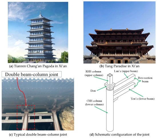
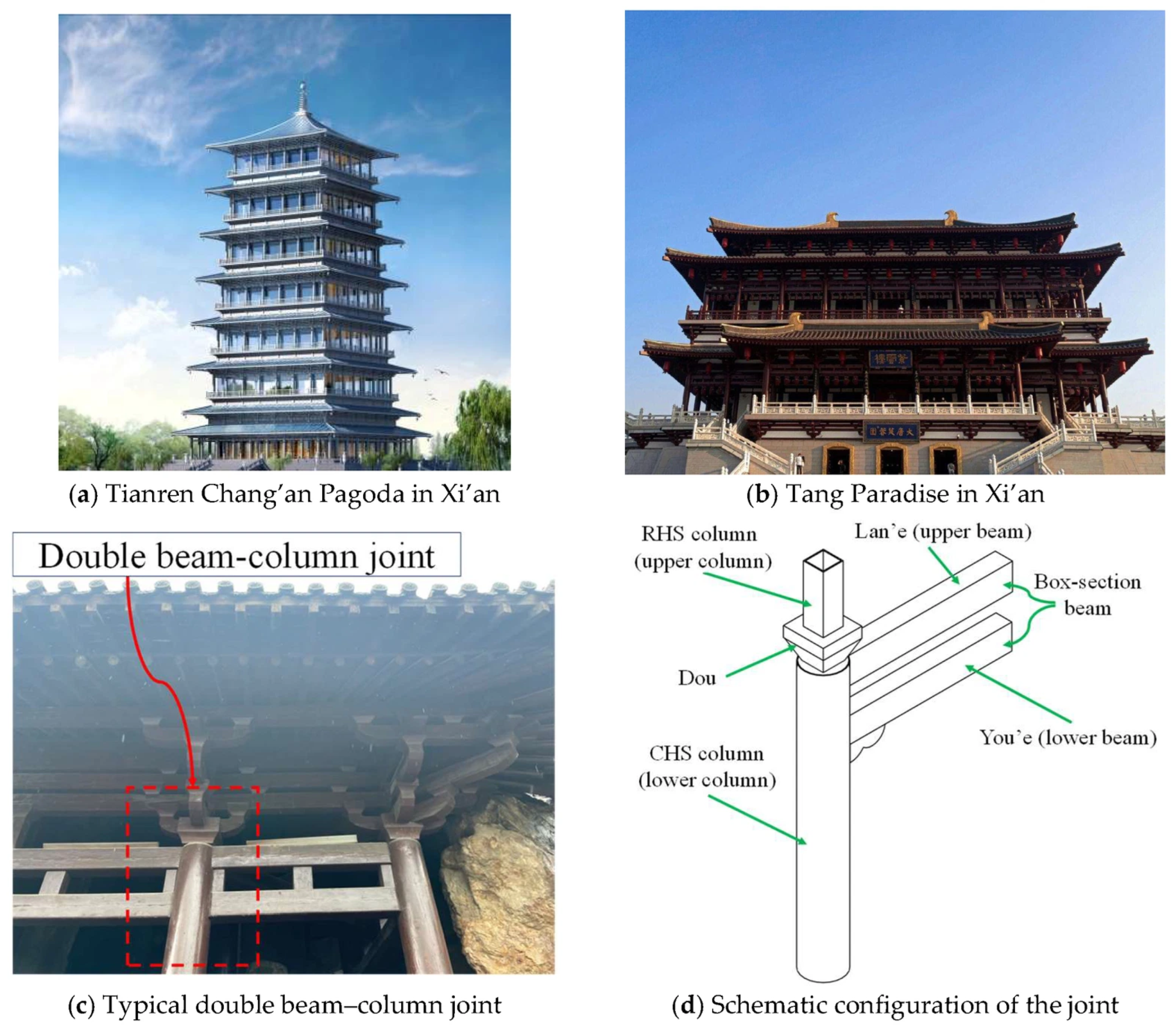
From the perspective of architectural history, traditional buildings in different regions have developed distinctive structural systems. While masonry load-bearing systems were widely used in Western traditional architecture, timber-frame structures represented by ancient Chinese buildings became an important architectural tradition in East Asia, influencing architectural development in Japan and Korea. With the globalization of modern construction technologies, preserving regional architectural identities while meeting contemporary building requirements has become an important challenge. The integration of modern structural technologies with traditional architectural forms provides a potential approach to addressing this challenge. Since the beginning of the 21st century, increasing demands for cultural heritage conservation, cultural tourism, and construction industrialization have promoted the development of steel Chinese traditional-style buildings (SCTBs), which combine modern steel structural systems and prefabricated construction technologies while retaining the architectural features of traditional buildings [1]. Compared with traditional timber structures, steel structures offer advantages such as lower self-weight, favorable ductility, suitability for standardized fabrication and on-site assembly, and greater adaptability to complex architectural forms. In recent years, projects such as the Tianren Chang’an Pagoda and Tang Paradise in Xi’an have demonstrated the engineering applicability of modern structural materials and industrialized construction technologies in traditional-style buildings, as illustrated in Figure 1a,b.
Figure 1.
Representative steel Chinese traditional-style buildings and a typical beam–column joint configuration.
Compared with conventional steel frames, SCTBs generally exhibit greater irregularity in beam and column sections, relative member positions, and joint configurations because of the requirements associated with traditional architectural forms, roof geometry, and decorative components, as illustrated in Figure 1c,d.
Some joints also involve combinations of circular hollow section (CHS) and rectangular hollow section (RHS) columns, single- and double-beam systems, and beams with different cross-sections, resulting in more complicated load-transfer paths, deformation mechanisms, and hysteretic responses in the joint region [2,3,4,5,6].
Most beam–column joints in existing SCTBs have adopted fully welded connections. Previous studies have shown that these joints can provide satisfactory load-carrying capacity and seismic performance. However, weld cracking or local brittle failure may still occur in the regions connecting the beam flanges to the column wall under repeated cyclic loading [7,8]. Wu et al. [9] investigated the seismic behavior and shear resistance of all-welded irregular joints in steel traditional Chinese buildings through experimental testing and numerical analysis. To improve the seismic performance of such irregular joints, viscous dampers, friction dampers, and shape memory alloy (SMA) devices have also been introduced into SCTB joints [10,11,12,13]. Men et al. [14] investigated the seismic performance of steel beam–column joints with replaceable T-stubs, focusing on damage control through the connection components. Li et al. [15] further studied the seismic fragility and resilience of steel frames with replaceable T-stub connection components. In addition, on-site welding requires strict construction conditions and quality control and may cause disturbance to existing structures and the surrounding environment in heritage conservation, protective covering of archaeological sites, and renovation projects. Therefore, the development of assemblable beam–column connections with satisfactory seismic performance is of practical importance. T-stub connections have been extensively investigated for beam-to-hollow-section column connections because of their relatively simple load-transfer mechanism and convenient assembly [16,17]. However, CHS columns are commonly used in SCTBs, and conventional high-strength bolts generally require access from both sides for installation and tightening. Their application is therefore restricted by the limited internal access of closed-section members [18,19]. Blind bolts can be installed and tightened from only one side of the connected member, providing an effective solution for connections involving closed sections. Combining blind bolts with T-stub connections can reduce on-site welding, improve assembly efficiency, and facilitate repair after local damage, thereby providing a feasible connection form for prefabricated SCTB joints.
In recent years, extensive studies have been conducted on blind bolts T-stub connections [20,21,22]. Previous experimental and numerical investigations have examined the tensile behavior, cyclic response, load-carrying capacity, and failure modes of various blind-bolted connections [23,24,25,26,27,28,29]. Zhang et al. [30] investigated the cyclic behavior of blind-bolted T-stub connections to concrete-filled double steel tubular columns and proposed a method for predicting their bending resistance. Han and Chan [31] examined the tensile behavior of demountable blind-bolted T-stub connections to hollow section columns and developed analytical methods for different failure modes. Bu et al. [32] investigated the tensile damage behavior of blind-bolted T-stub connections, including deformation of the hollow section column and fracture of the T-stub flange. Liu et al. [33] examined the cumulative damage of blind-bolted T-stub joints and established rotational stiffness degradation relationships considering damage. Regarding connection modeling, Fan and Zhao [34] developed a moment–rotation model for composite connections with curved endplates and blind bolts. Shen et al. [35] established a four-stage multilinear cyclic envelope model for partially restrained steel beam–column bolted T-stub connections based on experimental data. Subsequently, Shen et al. [36] developed a method for calibrating and predicting the parameters of the Pinching4 hysteretic model for bolted T-stub connections. These studies have advanced the understanding of blind-bolted connections and their nonlinear behavior. However, the investigated connections mainly differ from the irregular joint configurations of SCTBs, which involve special geometric requirements, single- and double-beam arrangements, and complex load-transfer paths. Restoring force models specifically developed for blind-bolted T-stub joints in SCTBs remain limited.
Unlike previous studies focusing on conventional welded or damping-equipped joints in SCTBs, this study investigated prefabricated blind-bolted T-stub joints with irregular single- and double-beam configurations. The proposed connection system combines blind bolts, T-stubs, and leveling plates to accommodate the special connection requirements of closed-section columns and facilitate prefabricated assembly. Low-cycle reversed loading tests were conducted on four specimens, including two single-beam joints and two double-beam joints. The failure modes, hysteretic responses, skeleton curves, and stiffness degradation characteristics were analyzed. Based on the experimental results, a restoring force model was developed by combining a trilinear backbone curve, stiffness degradation relationships, and hysteretic path rules. The proposed model was then evaluated by comparison with the experimental hysteretic curves. The findings provide a basis for seismic analysis of prefabricated joints in SCTBs and offer a reference for the engineering application of this connection system.
2. Experimental Program
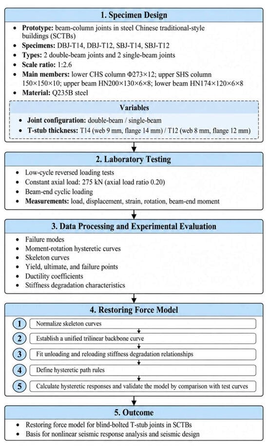
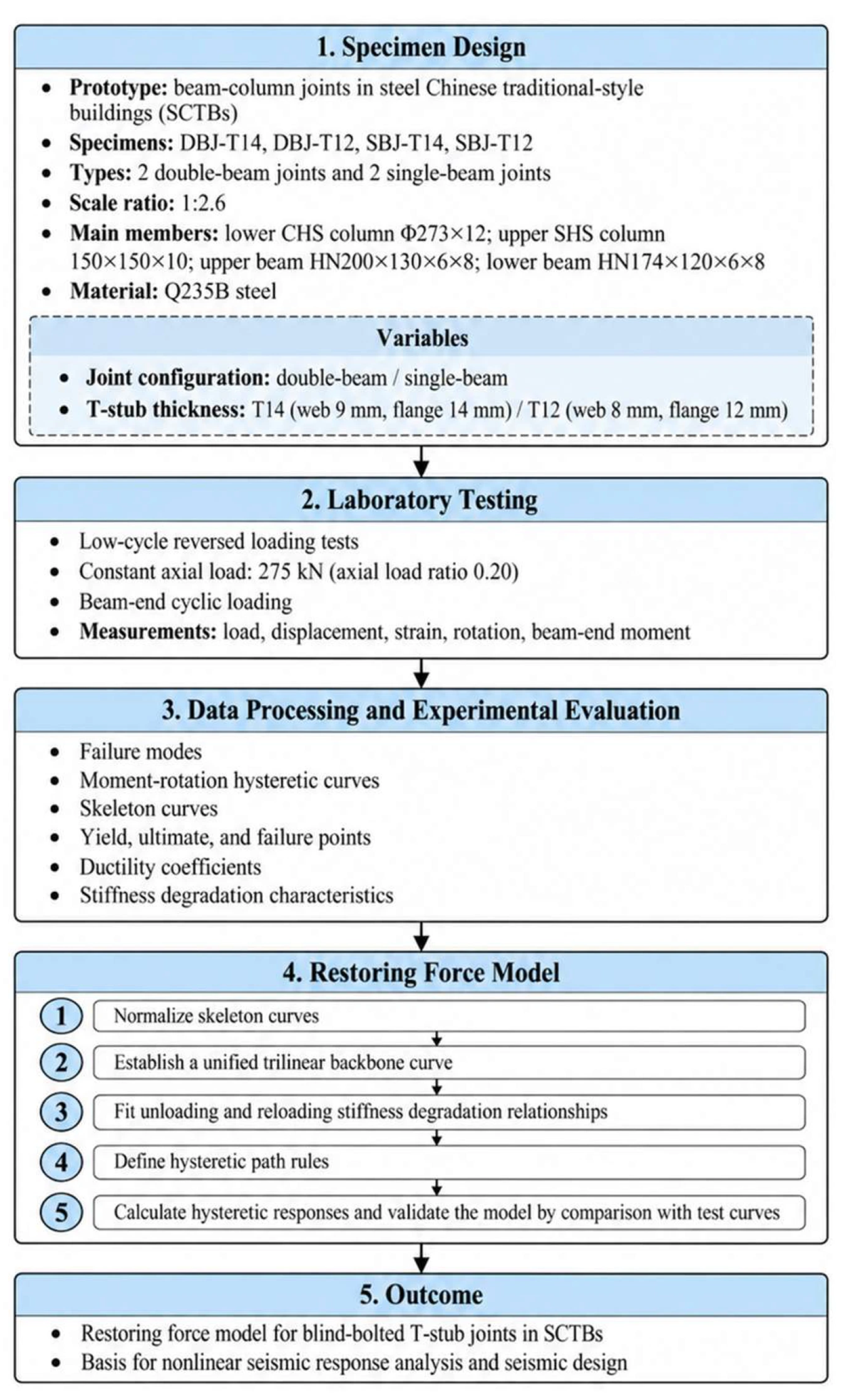
The overall research framework of the present study is shown in Figure 2. The study consisted of specimen design, laboratory testing, data processing and experimental evaluation, and restoring force model development. The specimen parameters and test variables are described first, followed by the loading protocol, measurement scheme, and the modeling procedure.
Figure 2.
Flowchart of the experimental program and restoring force modeling.
2.1. Specimen Design and Fabrication
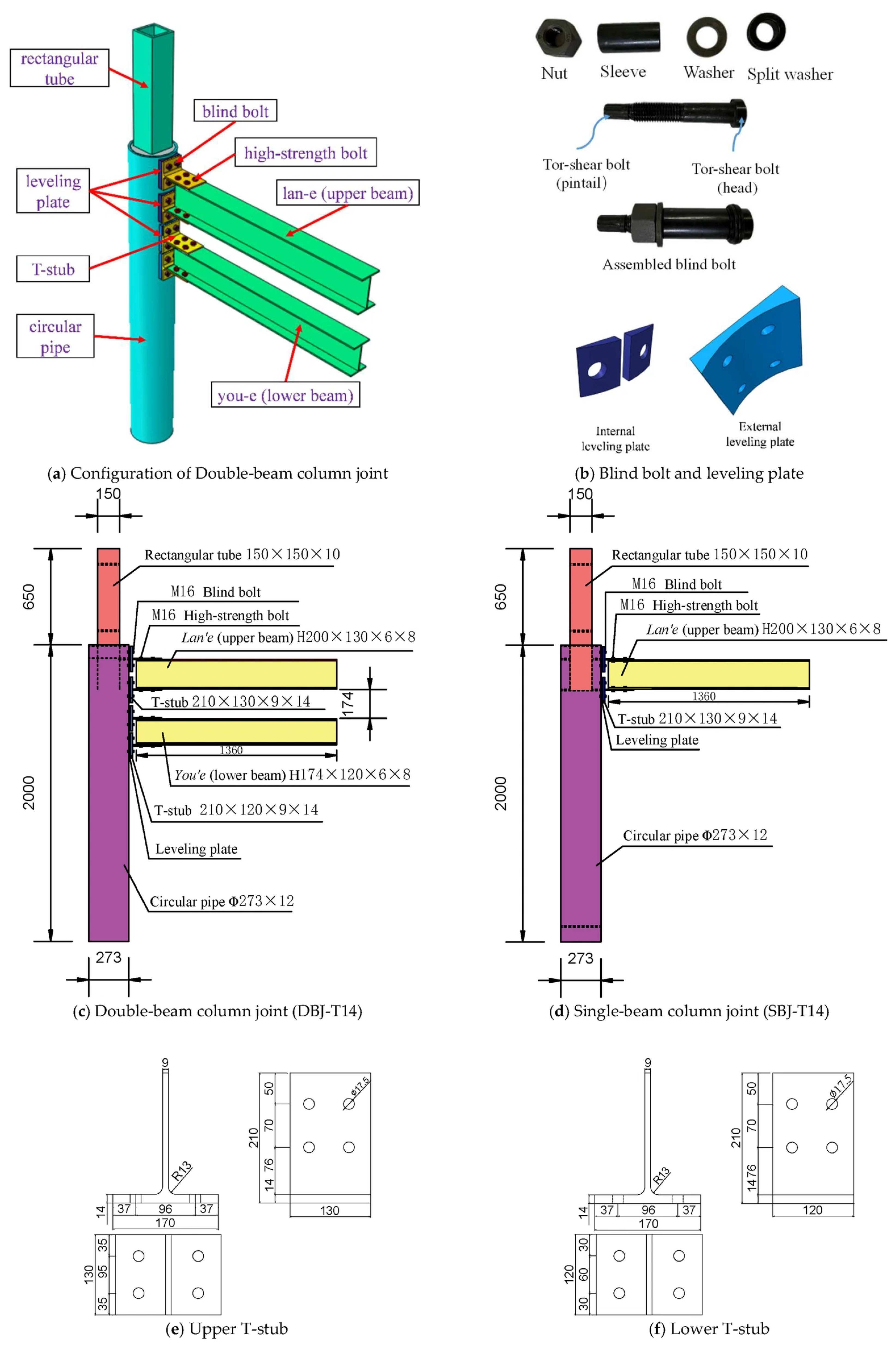
Four prefabricated joints using blind bolt T-stub connections were designed based on typical beam–column joints in SCTBs, including two double-beam joints and two single-beam joints. The prototype structure was selected from a second-class hall-style building in Xi’an, Shaanxi Province. In SCTBs, the lower column generally adopts a relatively large CHS, whereas the upper column adopts a smaller SHS to accommodate the installation of Dougong (traditional bracket sets) and other decorative components. The two column segments are connected through internal horizontal and vertical stiffeners to form a transition column. The double-beam joint consists of the Lan’e (upper beam), You’e (lower beam), and transition column, whereas only the Lan’e is retained in the single-beam joint.
The specimen dimensions were determined according to the material portion grading system documented in the Yingzao Fashi [37], together with the loading capacity of the laboratory equipment and the commercially available dimensions of seamless circular steel pipes. A geometric scale ratio of 1:2.6 was adopted. The lower column was a CHS with an outer diameter of 273 mm and a wall thickness of 12 mm, while the upper column was an SHS with a cross-section of 150 mm × 150 mm × 10 mm. The upper and lower beams adopted H200 × 130 × 6 × 8 and H174 × 120 × 6 × 8 sections, respectively. A constant axial load of 275 kN, corresponding to an axial compression ratio of 0.20, was applied at the column top. The main geometric parameters are summarized in Table 1.
Table 1.
Specimen details.
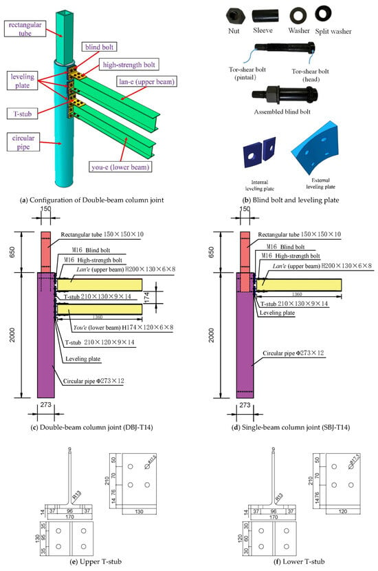
The joints employed a prefabricated connection system consisting of T-stubs, internal and external leveling plates, blind bolts, and high-strength bolts. The T-stubs were connected to the lower CHS column using M16 Grade 10.9 blind bolts and to the H-section beams using M16 Grade 10.9 high-strength bolts. All steel components were fabricated from Q235B steel. The beam and column sections and bolt arrangements were kept unchanged, while the T-stub dimensions were varied. Specimens DBJ-T14 and SBJ-T14 employed T-stubs with a web thickness of 9 mm and a flange thickness of 14 mm, whereas DBJ-T12 and SBJ-T12 employed T-stubs with corresponding thicknesses of 8 mm and 12 mm. The upper T-stub width was 130 mm, matching the upper-beam flange, while the lower T-stub width was 120 mm to match the lower-beam flange. The beam-side bolt-hole diameter was 17.5 mm, and the hole diameter in the CHS column and leveling plates was 24 mm to accommodate the blind-bolt sleeves.
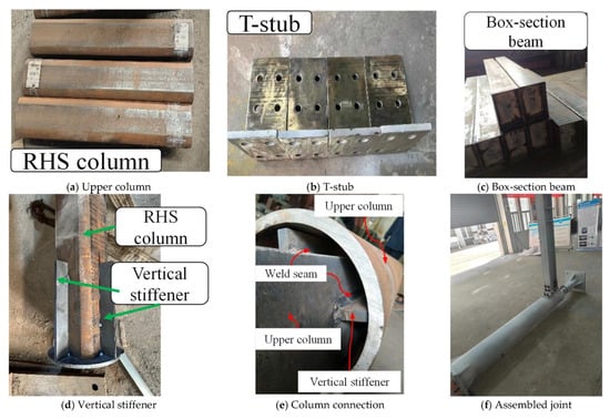
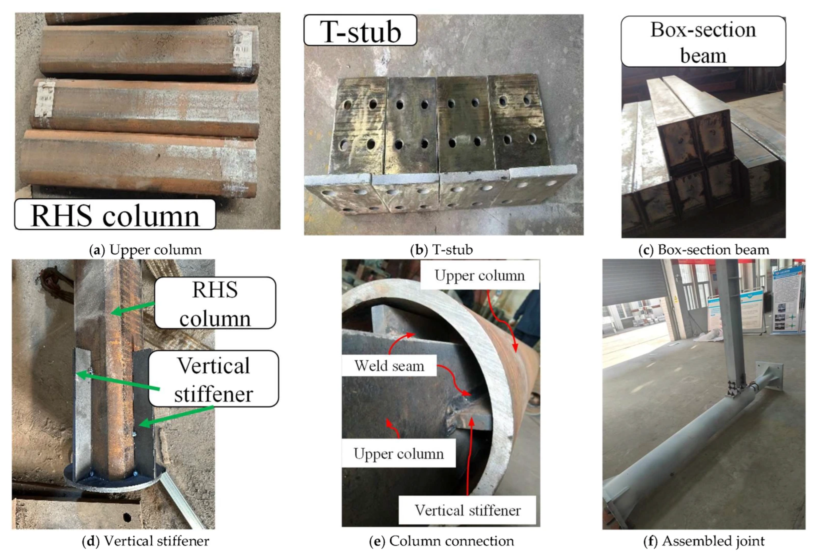
The joints were designed according to the strong-column–weak-beam principle. Horizontal ring stiffeners were provided inside the CHS column at the beam-flange levels, and the upper SHS column was embedded into the lower CHS column and connected through vertical stiffeners. The internal stiffening system was designed with reference to GB 50017-2017 [38], while the T-stubs and high-strength bolts were selected with reference to JGJ 82-2011 [39]. All components were prefabricated in the workshop. Access holes were provided in the CHS column for routing the blind-bolt strain-gauge wires, and 30 mm × 30 mm grids were marked in the joint region to facilitate observation of local deformation and damage during testing. The specimen configurations and geometric dimensions are shown in Figure 3. The main fabrication procedures are illustrated in Figure 4.
Figure 3.
Test specimens (Unit: mm).
Figure 4.
Fabrication process of the specimens.
2.2. Material Testing
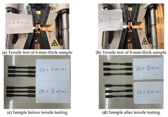
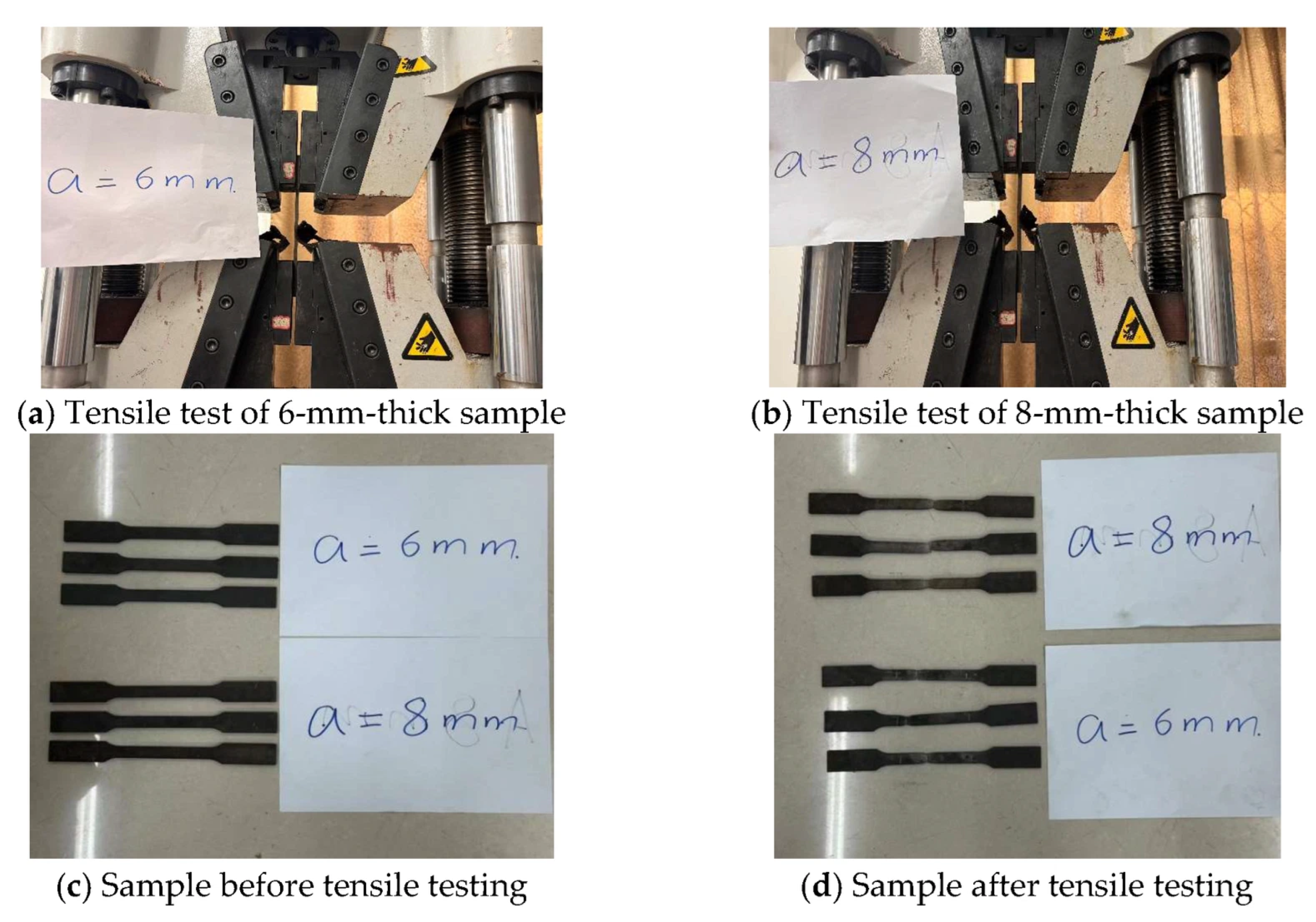
Prior to the cyclic loading tests, tensile samples were prepared from the main steel components in accordance with GB/T 228.1-2021 [40]. At least three standard tensile samples were prepared for each type of steel, and the average values were adopted as the material properties. The tensile tests were conducted at the Structural Engineering Laboratory of Henan University of Technology, as shown in Figure 5. The measured yield strength, ultimate tensile strength, elastic modulus, and elongation of the steel materials are summarized in Table 2.
Figure 5.
Material tensile tests.
Table 2.
Mechanical properties of steel materials.
2.3. Experimental Setup and Loading Scheme
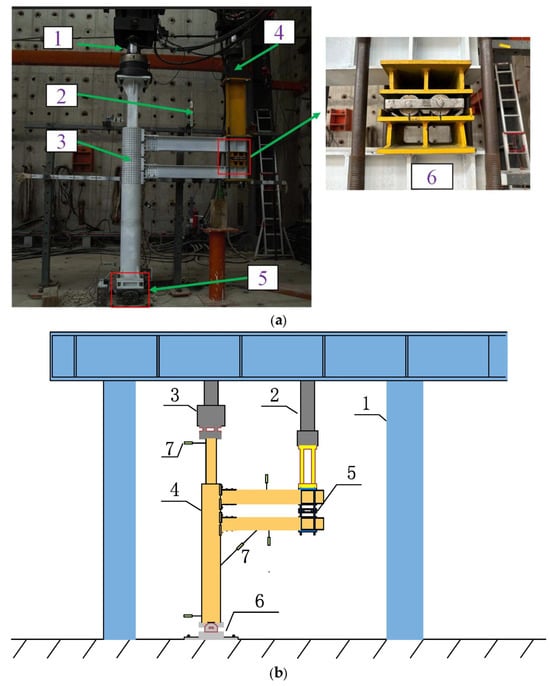
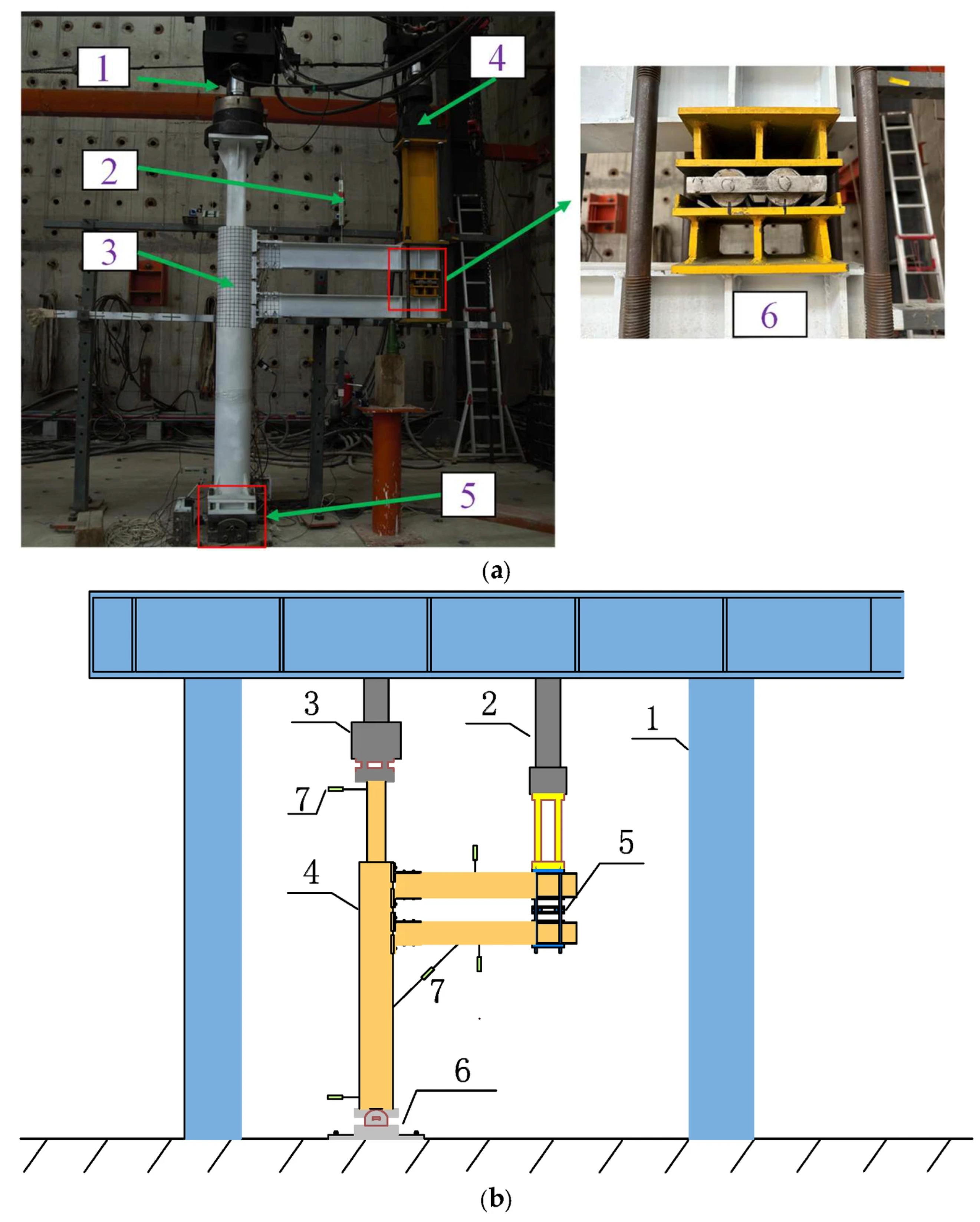
The test setup is illustrated in Figure 6. A constant vertical axial load of 275 kN was applied at the column top using a 2000 kN hydraulic actuator and was maintained throughout the cyclic loading process. The column base was supported by a unidirectional hinge and anchored to the rigid laboratory floor using ground anchor bolts. Low-cycle reversed loading was applied at the beam end using a 500 kN hydraulic servo actuator. To restrain out-of-plane movement of the beam end during cyclic loading, four chains were connected to the surrounding reaction system, thereby ensuring that the specimen response was primarily confined to the loading plane.
Figure 6.
Test setup. (a) On-site photograph. Note: 1. 2000 kN hydraulic actuator; 2. Displacement gauge; 3. Specimen; 4. 500 kN hydraulic servo actuator; 5. Hinged support; 6. Double-beam connector. (b) Schematic diagram. Note: 1. Reaction frame; 2. 200 t actuator; 3. 50 t actuator; 4. Specimen; 5. Double-beam connector; 6. Hinged support; 7. Displacement gauge.
For the double-beam joints, a specially designed double-beam connector was installed to reproduce the beam-end boundary conditions of the prototype structure, as shown in Figure 6a. The connector allowed relative horizontal movement between the Lan’e and You’e beam ends while restraining their relative vertical displacement, thereby maintaining the prescribed vertical spacing between the two beams and minimizing additional shear and moment transfer between them. This arrangement enabled the deformation compatibility of the double-beam system in SCTBs to be reasonably reproduced during cyclic loading.
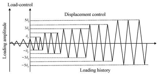
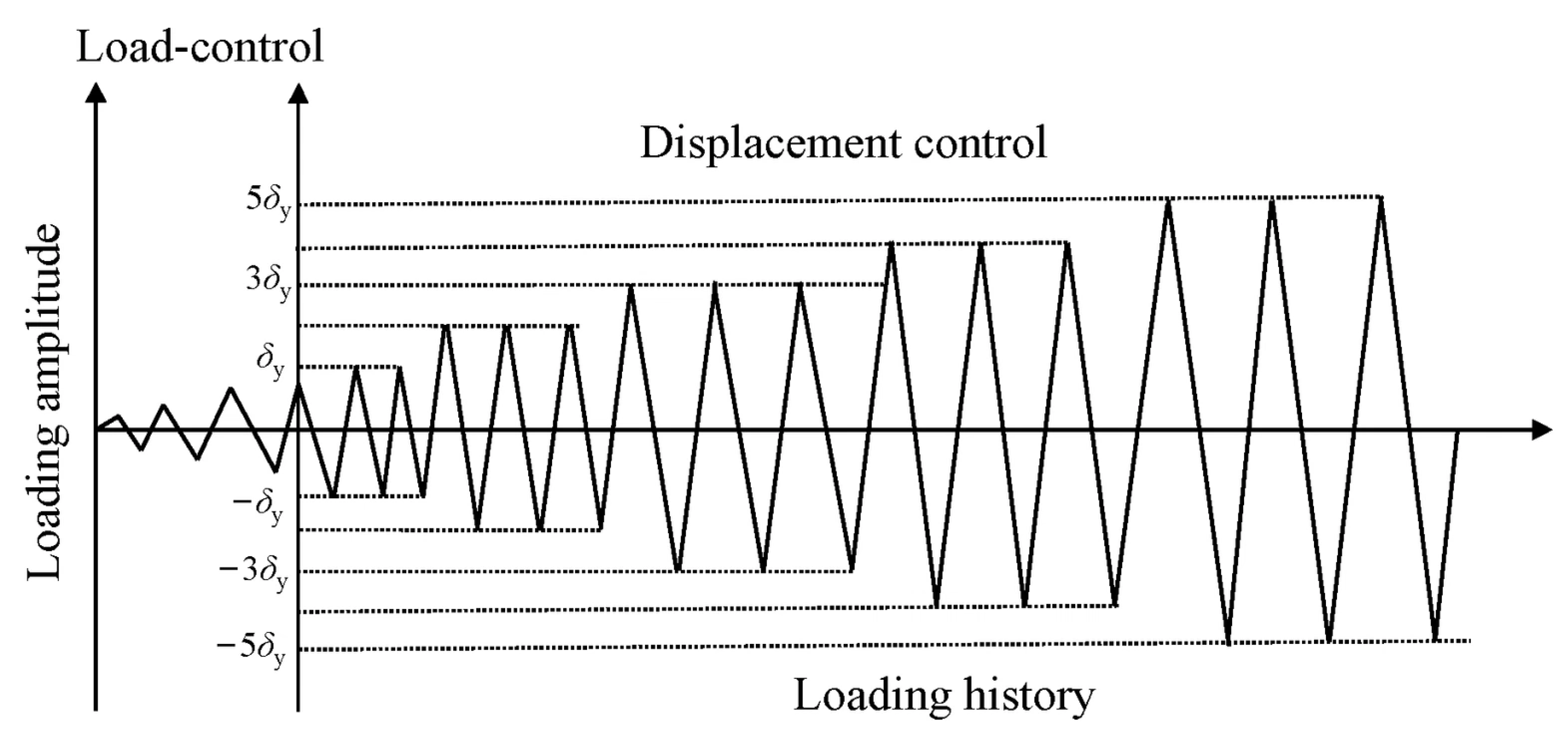
The loading protocol is shown in Figure 7. Before cyclic loading, the vertical axial load was applied at the column top in increments of 25 kN until the target axial load of 275 kN was reached. This axial load was then maintained constant throughout the subsequent cyclic loading process. A combined load–displacement control method was adopted at the beam end. The actuator extension direction was defined as positive, whereas the retraction direction was defined as negative.
Figure 7.
Loading protocol.
Load control was adopted before the strain at any critical measurement point reached the yield strain of the steel. Once yielding was detected, the loading mode was switched to displacement control. The beam-end displacement corresponding to specimen yielding, δy, was taken as the reference displacement, and the subsequent displacement amplitudes were increased progressively in integer multiples of δy, i.e., 1δy, 2δy, 3δy, and so forth. Three complete cycles were applied at each displacement level. The test was terminated when the load-carrying capacity decreased below 85% of the peak value or when severe damage prevented stable continuation of the loading.
2.4. Measurement Scheme
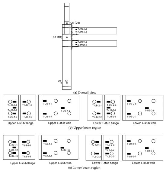
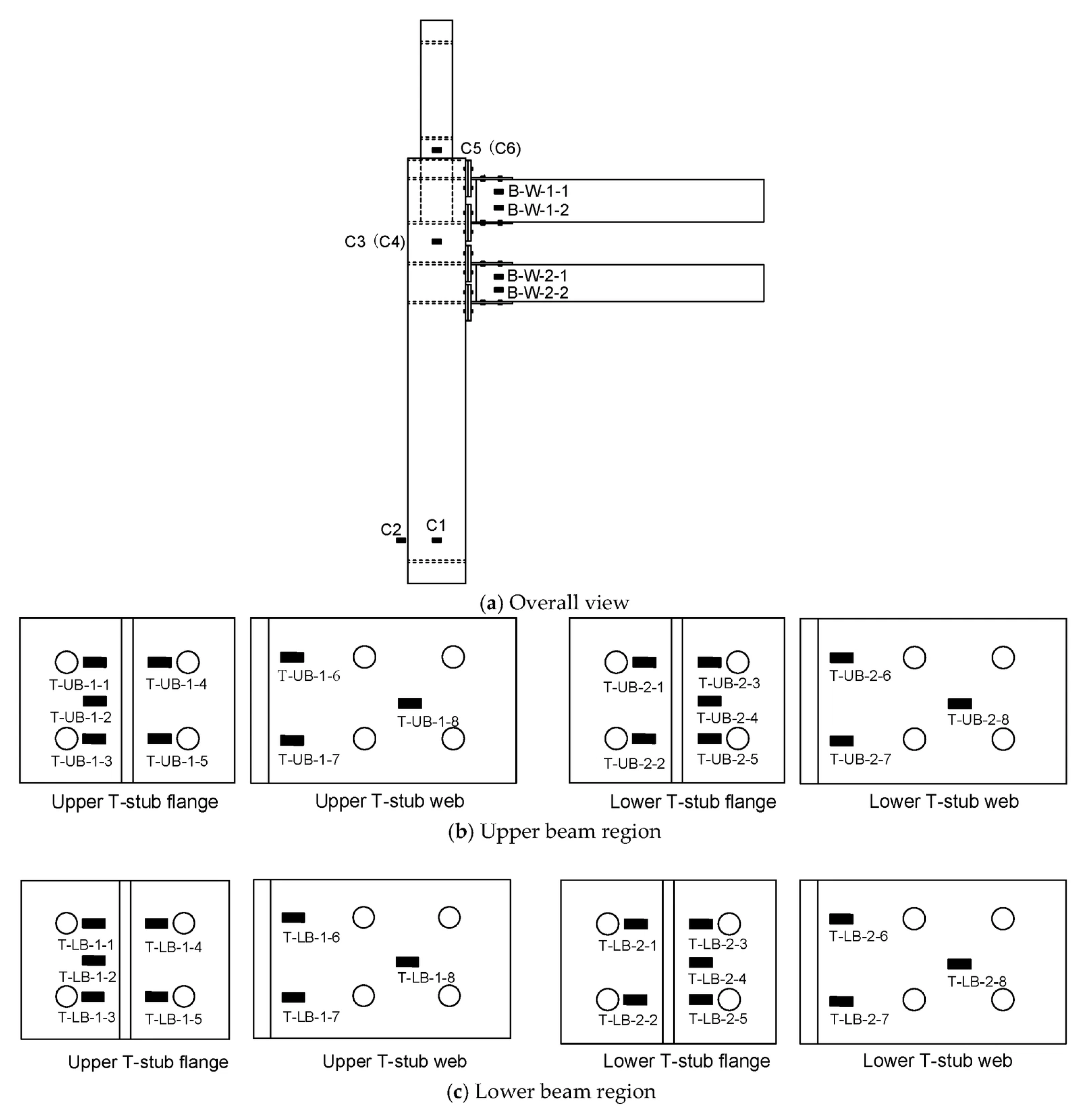
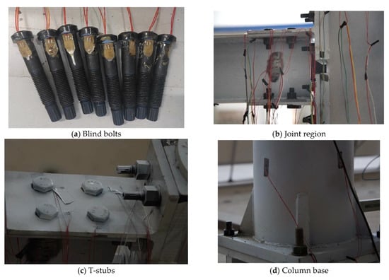
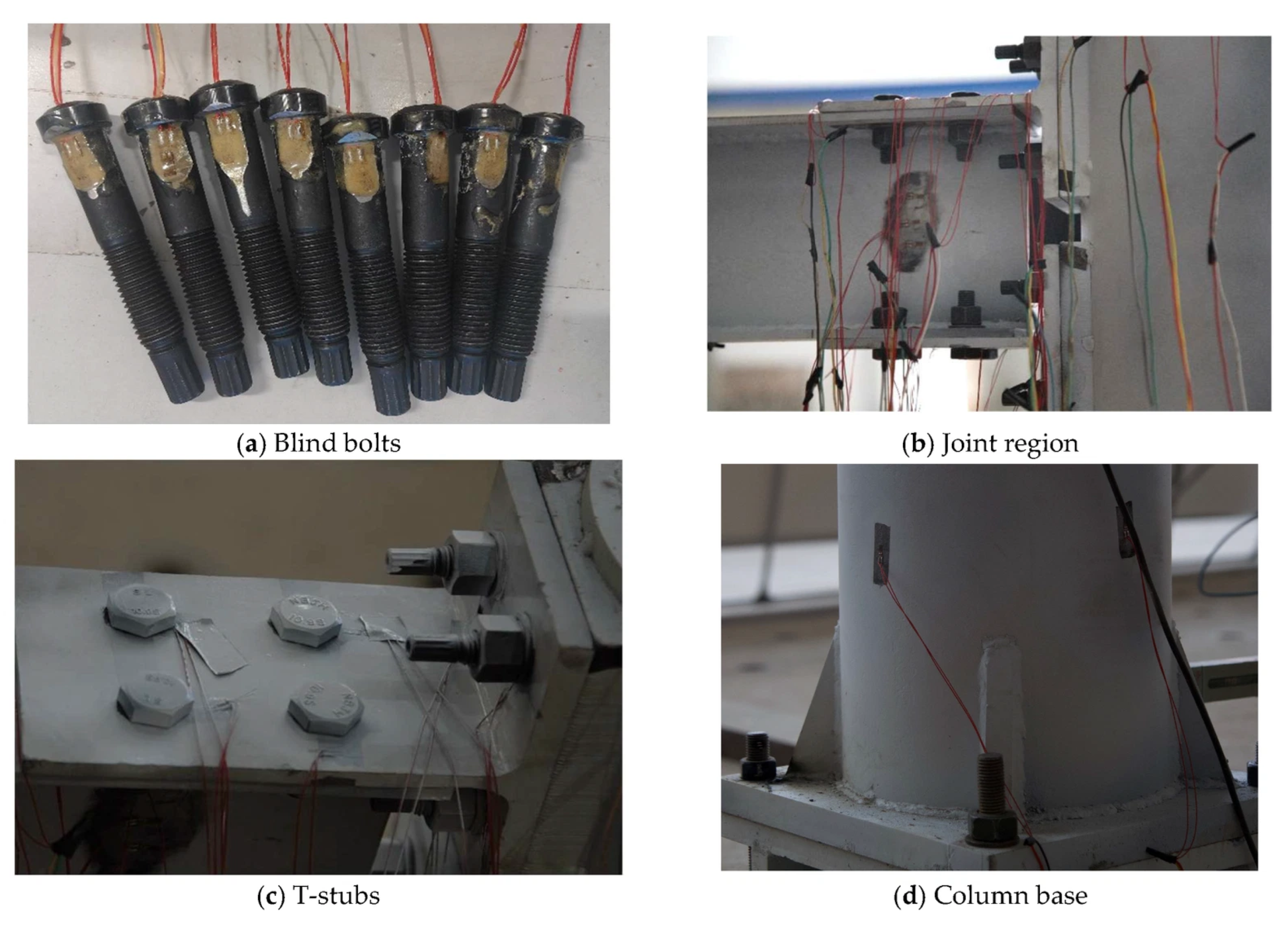
The beam-end load was measured using the load cell integrated into the electrohydraulic servo actuator supplied by Beijing Fluid Control System (FCS) Corp., Beijing, China. The actuator displacement was recorded simultaneously by the servo control system. Strain gauges were arranged at the column top, column base, beam ends, and joint region, with denser instrumentation on the T-stub flanges and webs to monitor local yielding and strain development. The strain gauge arrangement is shown in Figure 8 and Figure 9.
Figure 8.
Arrangement of strain gauges.
Figure 9.
Strain gauge installation on the specimens.
For the blind bolts, the unthreaded portion of the bolt shank was locally ground and instrumented with small strain gauges, as shown in Figure 9a. The lead wires were routed through the reserved openings in the CHS column, and the gauges were protected with an epoxy-based coating to prevent damage during bolt installation and tightening.
3. Test Results
3.1. Test Observations and Failure Modes
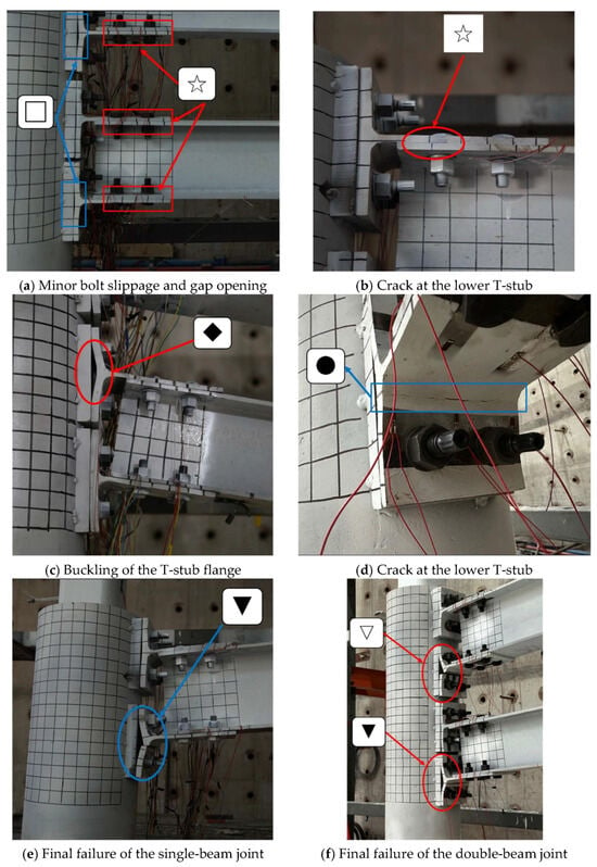
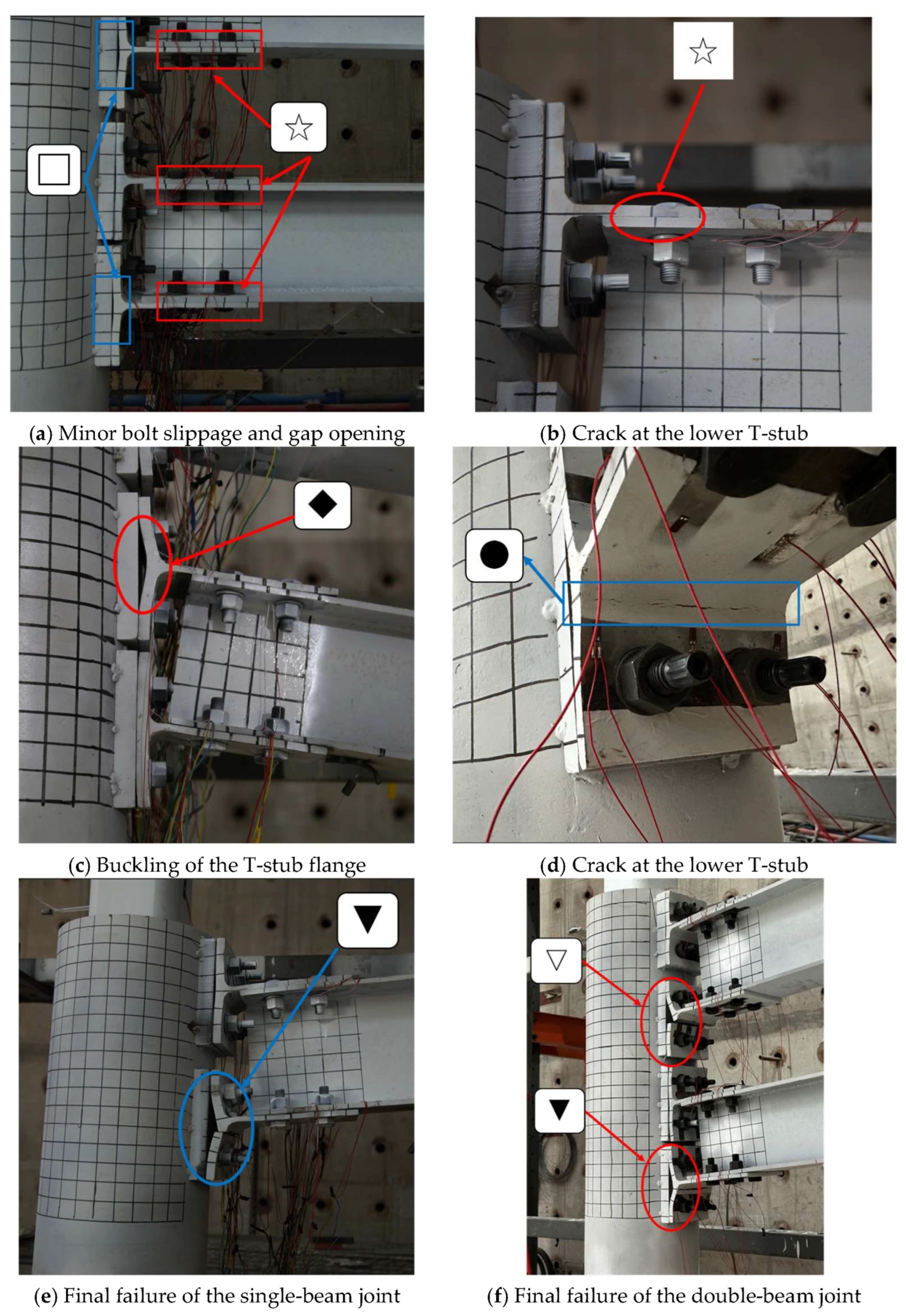
The typical failure phenomena of the specimens are shown in Figure 10, and the main observations are summarized in Table 3. All four specimens exhibited similar damage evolution under low-cycle reversed loading. Damage was mainly concentrated in the T-stub connection region, whereas no obvious damage was observed in the beams, columns, or joint core regions. The overall failure mode was consistent with the strong-column–weak-beam design principle.
Figure 10.
Failure modes of specimens. Note: ☆ denotes minor slippage of the high-strength bolts at the beam end; □ denotes minor gaps between the T-stub flange and the outer leveling plate; ◆ denotes buckling deformation of the T-stub flange; ● denotes cracking at the T-stub flange-web junction; ▽ denotes fracture of the lower T-stub on the upper beam; ▼ denotes fracture of the lower T-stub on the lower beam.
Table 3.
Main test phenomena of joints.
At the initial loading stage, the specimens remained essentially elastic. Only slight relative slip occurred at the T-stub-to-beam connections, and small gaps gradually developed between the upper and lower T-stub flanges and the external leveling plates. With increasing loading amplitude, yielding first occurred in the lower T-stub, followed by yielding at several measurement points on the T-stub web and beam end. Meanwhile, bending deformation of the T-stub flange became increasingly evident; the gaps between the flange and the external leveling plate widened, and bolt slip became more pronounced. The joints therefore gradually entered the plastic development stage. No obvious plastic deformation was observed in the external leveling plates or the column wall.
At the later loading stage, plastic deformation and cumulative damage became concentrated at the T-stub flange–web junction. With increasing displacement amplitude and loading cycles, cracks first initiated in this region and subsequently propagated until fracture occurred. For the single-beam joints, final failure was mainly governed by crack propagation and fracture at the flange–web junction of the lower T-stub. For the double-beam joints, both beam levels participated in resisting the applied load. After fracture of the T-stub associated with one beam level, the other beam level was still able to sustain part of the load, resulting in a more progressive failure process and a certain degree of load redistribution.
The local failure characteristics indicate that the T-stub flange–web junction was the primary region of plastic deformation and damage accumulation. This region not only exhibits a geometric discontinuity but also transfers the beam-end moment and shear force, making it susceptible to pronounced local tension–bending deformation under cyclic loading. In contrast, the blind bolts, leveling plates, and column wall generally remained intact, indicating that the major damage was confined to the T-stub connection components.
Overall, the failure process of the four specimens can be divided into three stages. The first is the local yielding stage, characterized by initial yielding of the T-stub and slight slip at the connection. The second is the damage development stage, during which bolt slip increases, flange bending becomes more pronounced, and local plastic deformation accumulates. The final stage is the failure stage, characterized by crack initiation, propagation, and eventual fracture at the T-stub flange–web junction. This damage evolution is consistent with the elastic, strengthening, and degradation stages identified from the subsequent skeleton curves and provides an experimental basis for the stiffness degradation relationships and hysteretic rules adopted in the restoring force model.
3.2. Hysteretic Response
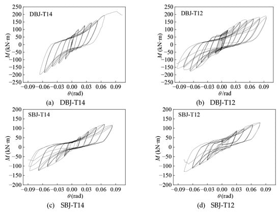
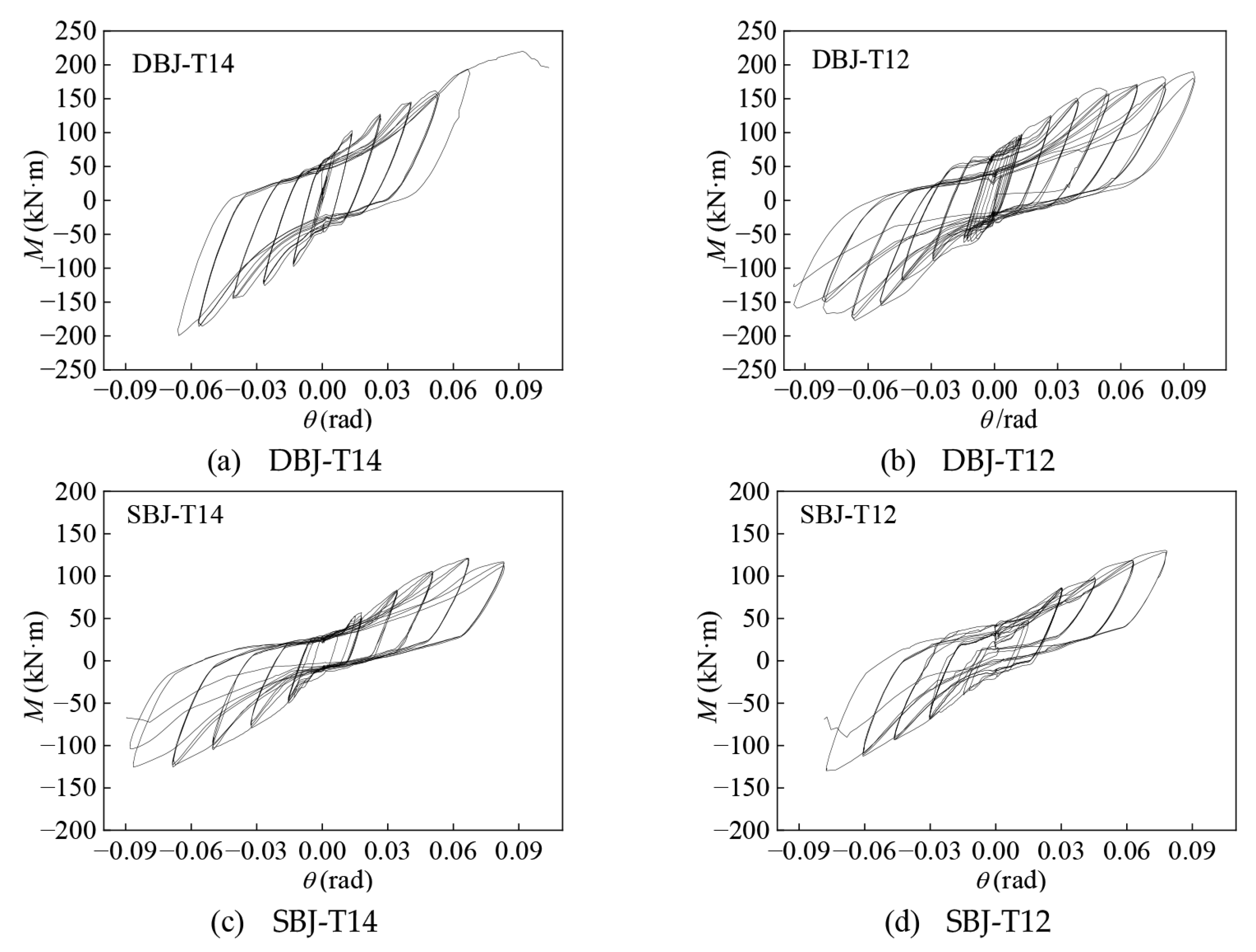
Figure 11 shows the moment–rotation hysteretic curves of the four specimens, where M and θ denote the beam-end moment and rotation, respectively. The hysteretic loops generally exhibited a spindle-shaped form and became progressively fuller with increasing loading amplitude, indicating a stable energy dissipation capacity. Plastic deformation was mainly concentrated in the local T-stub connection region, while no plastic hinge formed at the beam end. Consequently, the hysteretic loops were less full than those typically observed in conventional steel beam–column joints.
Figure 11.
Hysteretic curve of specimens.
At the initial loading stage, the specimens remained essentially elastic, and the moment–rotation relationship was approximately linear. The hysteretic loops were narrow, with small enclosed areas and limited residual deformation. As the loading amplitude increased, slight slip occurred at the high-strength bolted connections at the beam ends, accompanied by relative movement between the T-stub webs and the beam flanges. Under repeated loading, the gaps between the T-stub flanges and the external leveling plates gradually widened, and bending deformation of the T-stub flanges became increasingly pronounced. The hysteretic loops consequently expanded, indicating progressive development of plastic deformation. At the later loading stage, cracks initiated at the T-stub flange–web junction and subsequently propagated until fracture occurred. A pronounced reduction in moment was observed during the negative loading branch after local fracture, reflecting degradation of the connection stiffness and load-carrying capacity.
The hysteretic responses of the four specimens differed mainly because of the configuration and number of T-stub components. For the single-beam specimens SBJ-T14 and SBJ-T12, the beam and column sections and the overall connection configuration were identical, while the T-stub dimensions differed. Both specimens exhibited similar plastic development, which was governed primarily by tension–bending deformation of the T-stub flanges. Therefore, their hysteretic loops showed generally similar shapes and evolution trends. In contrast, the double-beam specimens DBJ-T14 and DBJ-T12 contained a larger number of T-stub components within the joint region. Multiple T-stub flanges participated in resisting cyclic deformation, resulting in higher rotational stiffness and a more stable energy dissipation process. Accordingly, the hysteretic loops of the double-beam specimens were generally fuller and enclosed larger areas than those of the single-beam specimens.
Overall, the four specimens exhibited a clear transition from elastic response to plastic development and subsequent strength degradation. The evolution of the hysteretic loops was consistent with the observed bolt slip, T-stub flange deformation, and eventual fracture at the flange–web junction. These features also provide the experimental basis for the subsequent definition of the skeleton curve and stiffness degradation rules.
3.3. Skeleton Curve
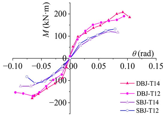
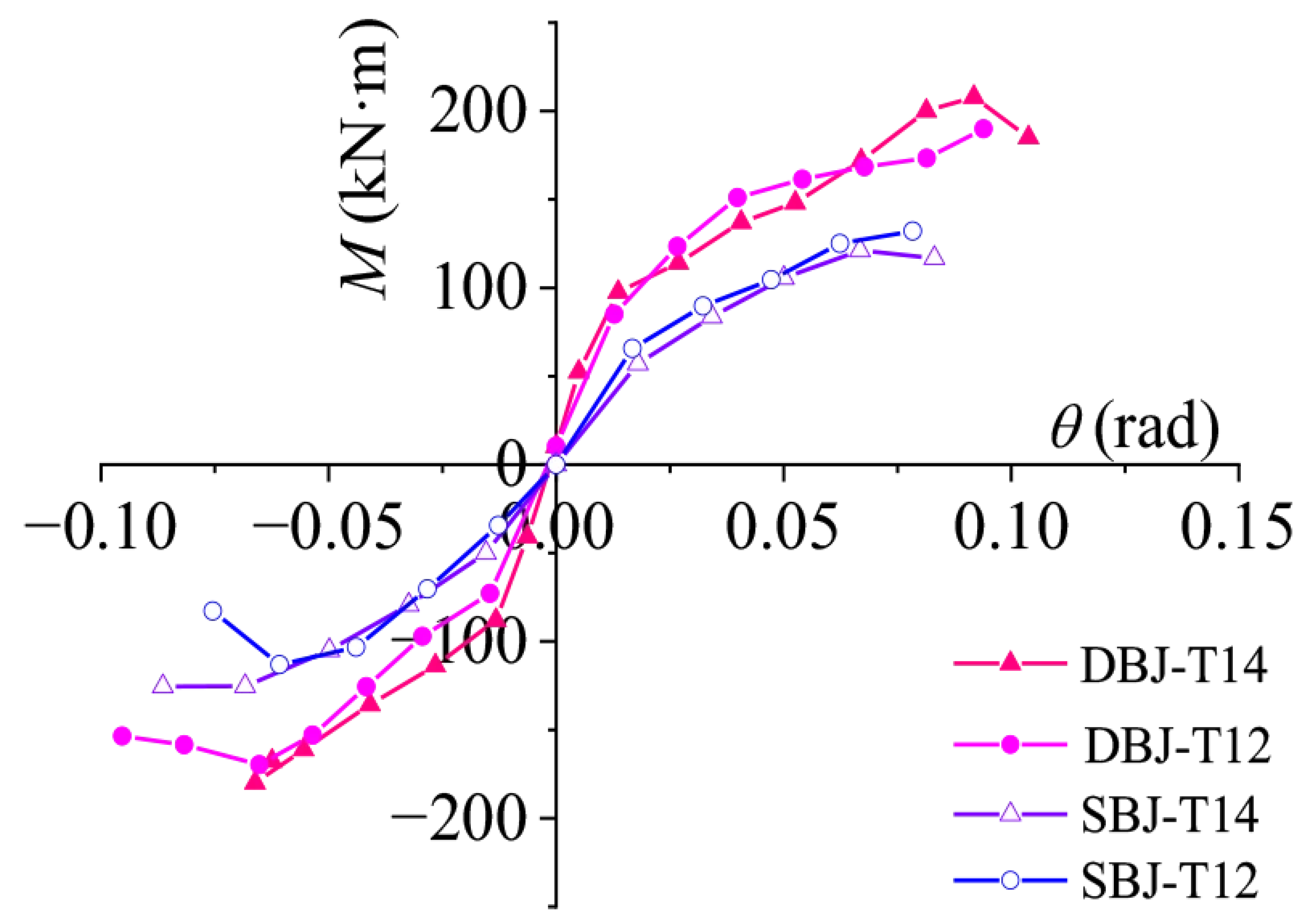
The skeleton curves of the specimens were obtained by connecting the peak points of the first cycle at each loading level from the moment–rotation hysteretic curves shown in Figure 11, as presented in Figure 12. The four specimens exhibited similar overall trends, with three characteristic stages: elastic response, yielding and plastic development, and strength degradation. Clear changes in slope were observed near yielding, and the general evolution of the skeleton curves was consistent with that reported for similar T-stub connections in previous studies [28,29].
Figure 12.
Skeleton curves of the specimens.
Before noticeable slip occurred at the beam-end bolted connections, the skeleton curves of specimens with the same joint configuration were relatively close, indicating similar initial stiffness and load-carrying response. As bolt slip developed, the restraint provided by friction at the connection interfaces gradually decreased, and the skeleton curves began to deviate from their initial linear trends. With increasing loading amplitude, pronounced plastic deformation developed in the T-stub flanges, resulting in a gradual reduction in the slope of the skeleton curves. At the later loading stage, fracture occurred at the flange–web junction of the lower T-stub under negative loading, leading to a rapid reduction in load-carrying capacity and a distinct descending branch in the skeleton curves.
The differences among the skeleton curves were mainly associated with the dimensions and number of T-stub components. During loading, the beam-end moment was transferred through the high-strength bolted connection to the T-stubs, and the development of joint resistance was governed primarily by the tension–bending response of the T-stub flanges. For the single-beam specimens SBJ-T14 and SBJ-T12, the beam and column sections and the overall connection configuration were identical, while the T-stub dimensions differed. SBJ-T14 exhibited a higher peak resistance than SBJ-T12, particularly in the negative loading direction, indicating that increasing the T-stub thickness enhanced the flexural resistance of the joint. In comparison, the double-beam specimens DBJ-T14 and DBJ-T12 contained a larger number of T-stub components within the joint region. The participation of multiple T-stubs in moment transfer and deformation increased the overall load-carrying capacity, resulting in generally higher skeleton curves and larger peak moments than those of the single-beam specimens.
Based on the skeleton curves, the characteristic points corresponding to yielding, ultimate resistance, and failure were identified for each specimen in both loading directions. The corresponding rotation and moment values are summarized in Table 4. Here, θy and My denote the rotation and moment at the yield point, θu and Mu represent those at the ultimate point, and θm and Mm correspond to the failure point. For certain loading directions, fracture occurred at the T-stub flange–web junction immediately after the peak moment was reached, resulting in a sudden loss of load-carrying capacity without a stable post-peak descending branch. Therefore, the failure point was taken as the ultimate point in these cases, resulting in identical ultimate and failure moment and rotation values. These characteristic parameters were subsequently used for normalization of the skeleton curves and formulation of the restoring force model.
Table 4.
Characteristic points of all specimens.
4. Development of Restoring Force Model
4.1. Backbone Curve Model
Based on the low-cycle reversed loading test results, a restoring force model was developed to describe the nonlinear moment–rotation response of the proposed T-stub joints with blind bolts and to provide a basis for the nonlinear seismic analysis of SCTBs. Previous studies have shown that the selection of steel material models can affect the numerical seismic assessment of steel frames [41]. However, the restoring force model in this study was established by directly fitting the experimental moment–rotation data, without using a steel constitutive model or finite element analysis.
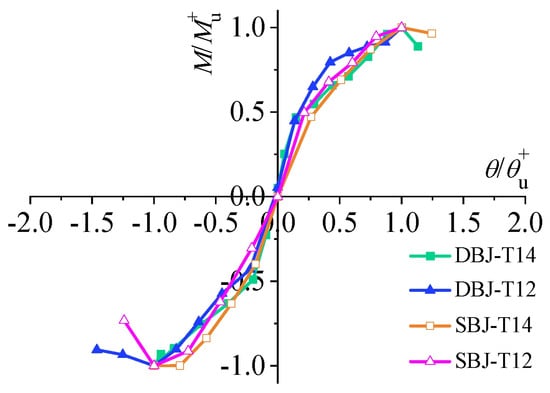
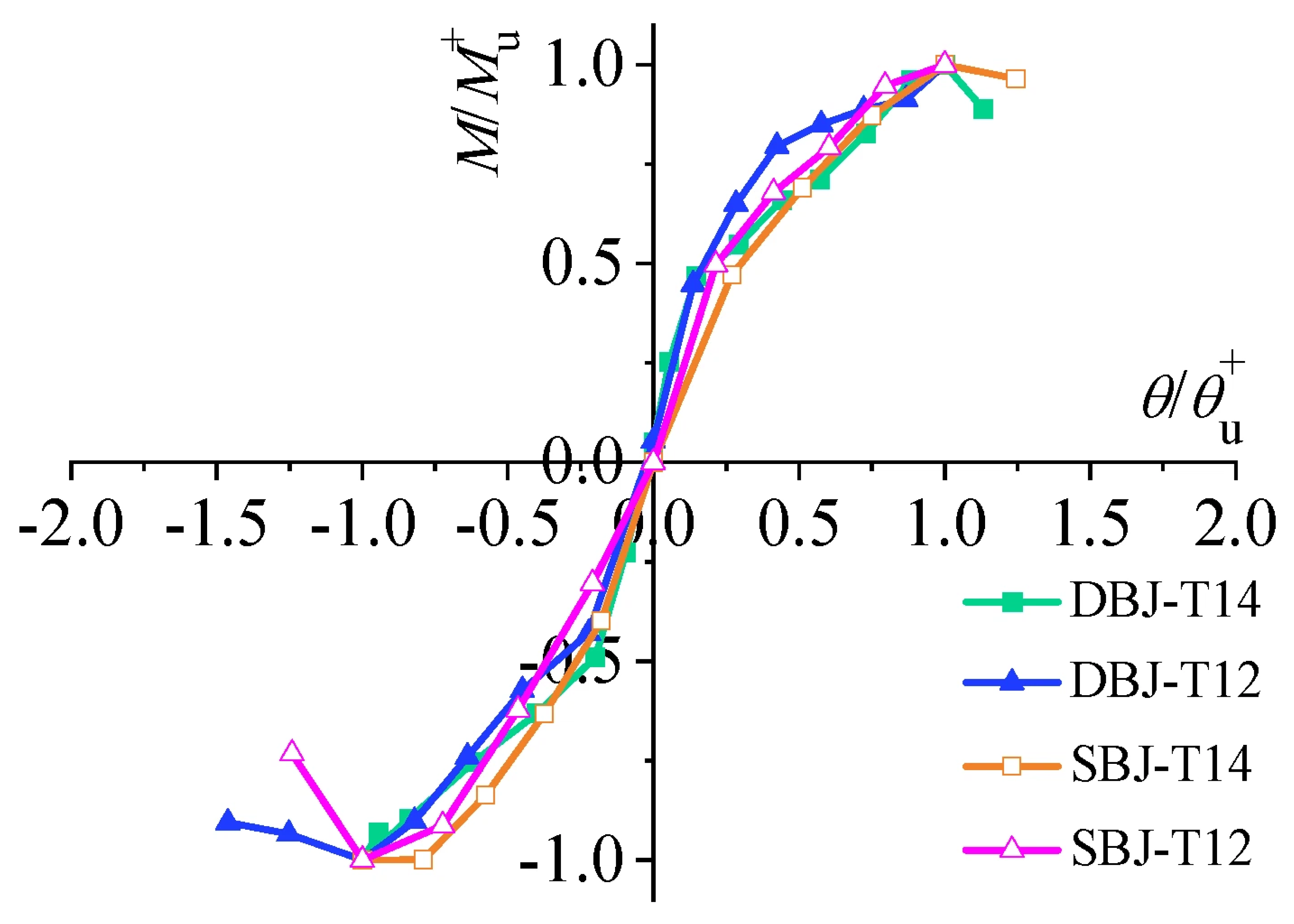
To establish a unified restoring force model, the skeleton curves of the four specimens were first normalized. The normalized moment M/Mu was adopted as the vertical coordinate, and the normalized rotation θ/θu was used as the horizontal coordinate, where Mu and θu denote the ultimate moment and the corresponding rotation, respectively. The characteristic values were determined from the skeleton curves according to the procedure described in Section 3.3. Positive and negative loading branches were normalized independently using their respective ultimate moment and rotation values.
The normalized skeleton curves of the four specimens are shown in Figure 13. Although the specimens exhibited considerable differences in absolute moment resistance and deformation capacity, their normalized skeleton curves showed similar overall development trends. The response could generally be divided into three stages: an elastic stage, a post-yield strengthening stage, and a post-peak degradation stage. This similarity indicates that a unified three-segment backbone curve can be used to represent the principal nonlinear characteristics of the investigated joints.
Figure 13.
Normalized skeleton curves of the tested joints.
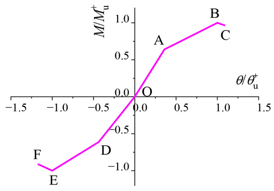
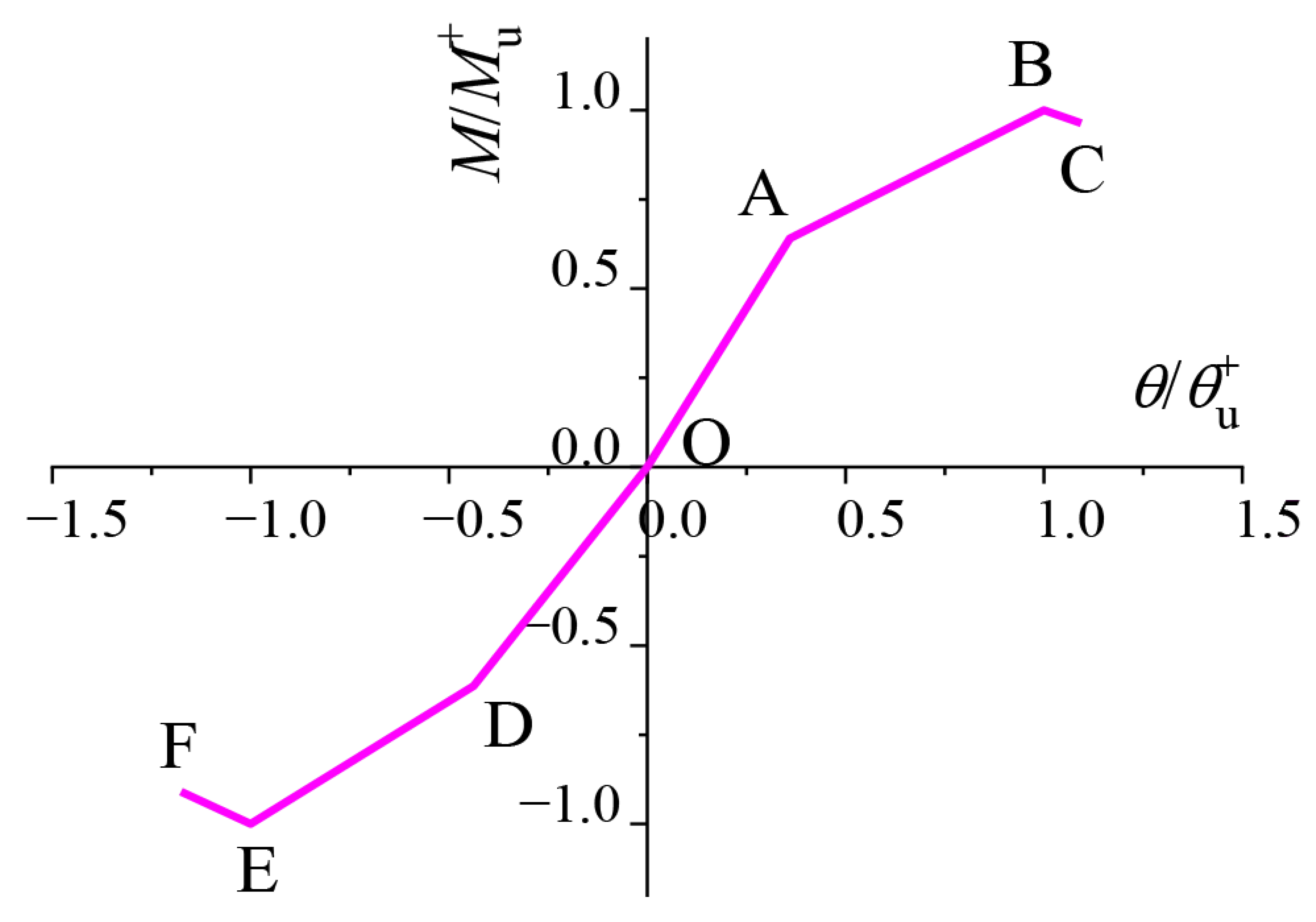
The three stages of the backbone curve also reflect the evolution of the dominant deformation mechanisms of the blind-bolted T-stub joints. In the first stage, corresponding to segments OA and OD, the joints remained essentially elastic, with only minor slip at the bolted interfaces and limited deformation of the T-stub components. In the second stage, represented by segments AB and DE, yielding and bending deformation gradually developed in the T-stub flanges, accompanied by increasing slip at the bolted connections, while the joint resistance continued to increase at a reduced rate. In the third stage, represented by segments BC and EF, cumulative plastic deformation and local damage were concentrated at the T-stub flange–web junction. Crack initiation and propagation in this region eventually resulted in strength degradation and the descending branch of the skeleton curve.
Figure 14 illustrates the three-segment backbone curve adopted for the proposed T-stub joints with blind bolts. The positive branch consists of segments OA, AB, and BC, while the negative branch consists of segments OD, DE, and EF. Points A and D represent the yield points, points B and E denote the ultimate points, and points C and F correspond to the failure points. Linear regression was performed using the normalized experimental skeleton-curve data of the four specimens to determine the equations of the individual segments. For the elastic segments OA and OD, the regression lines were constrained to pass through the origin, consistent with the physical condition of zero moment at zero rotation. Independent regression was performed for the positive and negative branches because evident asymmetry was observed between the two loading directions.
Figure 14.
Trilinear skeleton curve model.
Taking the positive elastic segment OA as an example, constrained linear regression was performed using the normalized experimental data of the four specimens as follows:
Using the same procedure, the equations of the remaining backbone-curve segments were obtained, and the results are summarized in Table 5.
Table 5.
Linear equations of the skeleton curve model.
As shown in Table 5, the fitted parameters of the positive and negative branches were not identical, indicating asymmetric moment–rotation responses under reversed loading. This asymmetry was associated with the different force-transfer paths and deformation states of the upper and lower T-stub components during cyclic loading. Therefore, separate equations were adopted for the positive and negative branches to better represent the experimentally observed response.
4.2. Stiffness Degradation Model
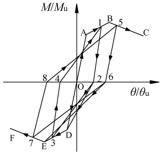
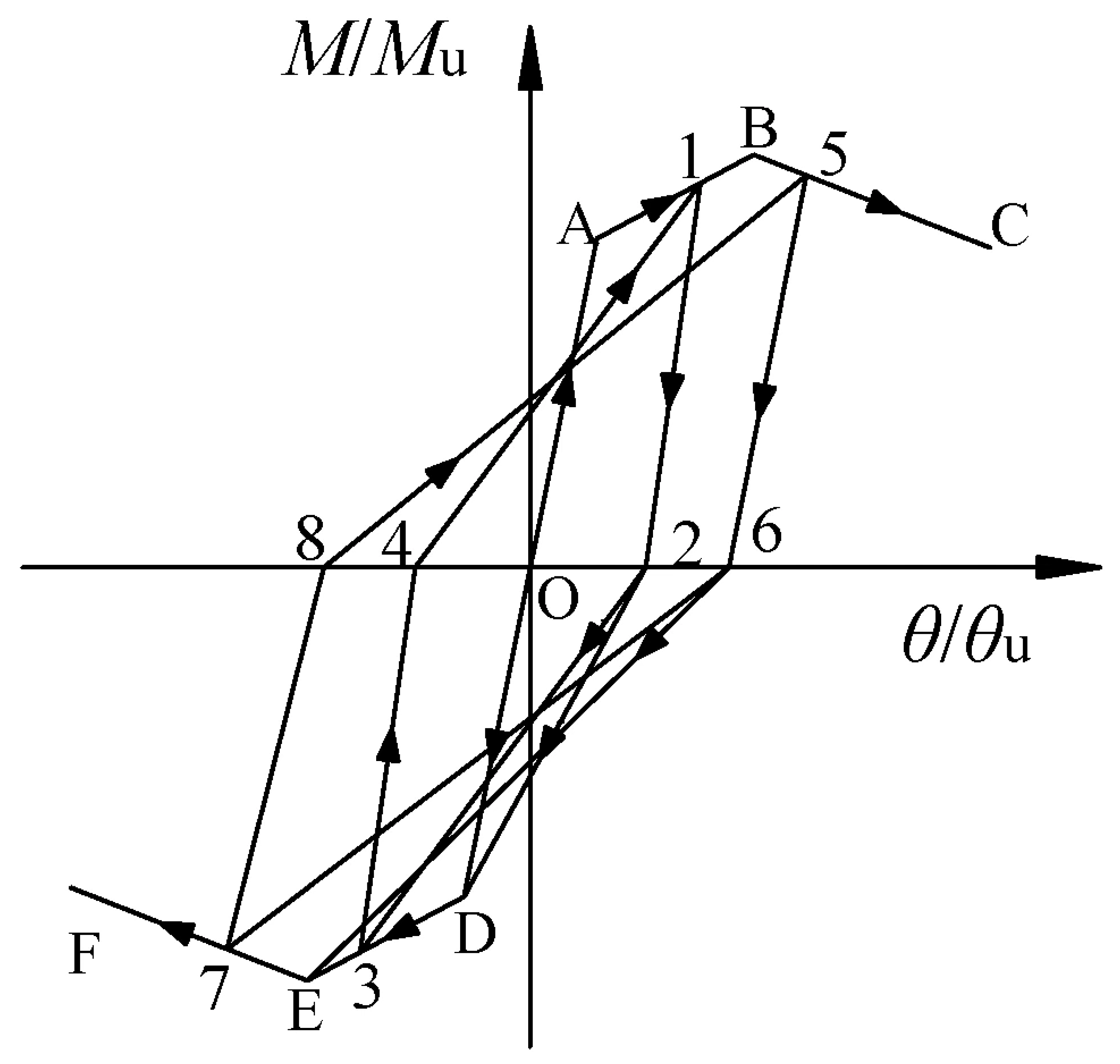
After the joints entered the plastic stage, repeated slip at the bolted interfaces, progressive bending deformation of the T-stub flanges, and cumulative damage at the T-stub flange–web junction resulted in gradual degradation of the unloading and reloading stiffness. To characterize this degradation behavior, four stiffness parameters were defined according to Figure 15: the positive unloading stiffness K1, negative reloading stiffness K2, negative unloading stiffness K3, and positive reloading stiffness K4. Specifically, K1 represents the unloading stiffness from the positive reversal point 1 to the zero-moment point 2, K2 represents the subsequent reloading stiffness from point 2 toward the negative loading branch, K3 denotes the unloading stiffness from the negative reversal point 3 to the zero-moment point 4, and K4 represents the reloading stiffness from point 4 toward the positive loading branch. Each stiffness was determined from the slope of the corresponding unloading or reloading path.
Figure 15.
Definition of loading and unloading stiffness parameters.
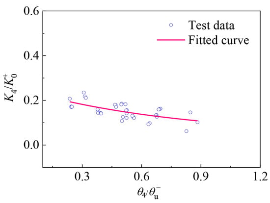
To facilitate comparison among specimens with different rotational capacities and initial stiffnesses, the stiffness degradation parameters were normalized. The characteristic rotations associated with the unloading and reloading paths were normalized by the corresponding ultimate rotations, while K1 and K4 were normalized by the initial positive stiffness K0+, and K2 and K3 by the initial negative stiffness K0−. The initial stiffnesses K0+ and K0− were obtained from linear regression of the experimental moment–rotation data in the elastic stage, corresponding to segments OA and OD of the backbone curve, respectively.
The normalized experimental results showed that the unloading and reloading stiffnesses decreased continuously with increasing deformation, indicating a pronounced nonlinear stiffness degradation response. This behavior is mainly attributed to the accumulation of bolt slip, plastic deformation of the T-stub flanges, and local damage at the flange–web junction under repeated cyclic loading. Therefore, nonlinear regression was employed to establish continuous degradation relationships for K1–K4, which were subsequently incorporated into the restoring force model to describe the cyclic unloading and reloading behavior of the joints.
(1) Degradation relationship of K1
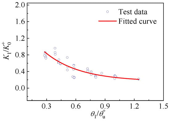
The degradation relationship of the positive unloading stiffness K1 was characterized by the normalized parameters K1/K0+ and θ1/θu+. The unloading stiffness K1 was determined from the slope of the unloading branch between the positive reversal point (Point 1) and the zero-moment point (Point 2). The stiffness and rotation parameters were then normalized, and an exponential function was adopted to describe the degradation relationship. The fitted degradation curve of K1 is shown in Figure 16.
Figure 16.
Degradation relationship of positive unloading stiffness.
The degradation equation of K1 can be expressed as
(2) Degradation relationship of K2
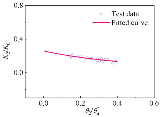
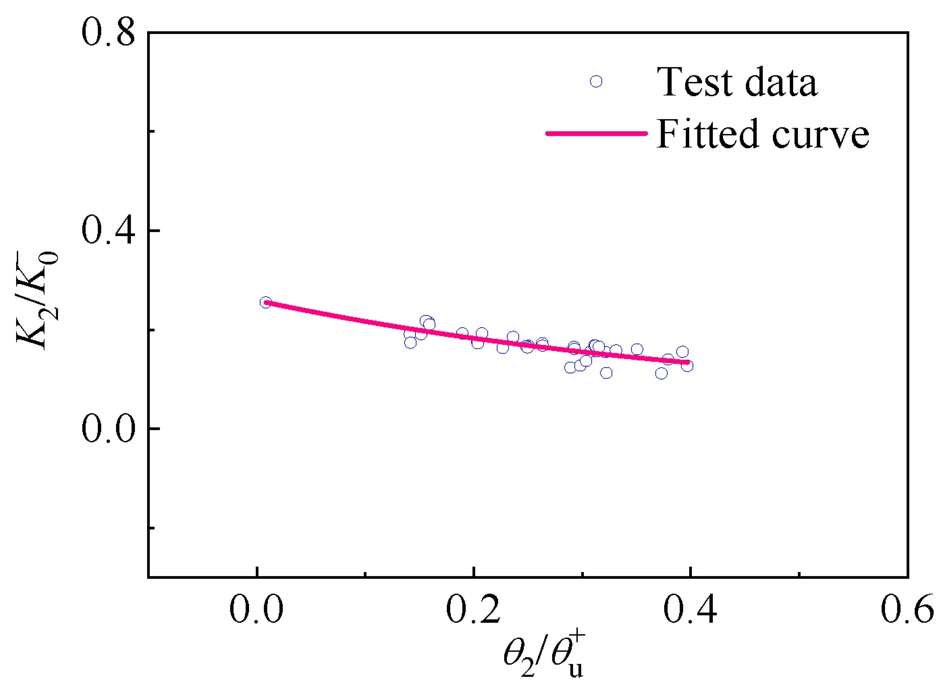
The degradation relationship of the negative reloading stiffness K2 was described by the relationship between K2/K0− and θ2/θu+. The reloading stiffness K2 was determined from the slope between the zero-moment point (Point 2) and the negative loading point (Point 3). The normalized data were then fitted using an exponential function, and the degradation curve of K2 was obtained, as shown in Figure 17.
Figure 17.
Degradation relationship of negative reloading stiffness.
The degradation equation of K2 can be expressed as
(3) Degradation relationship of K3
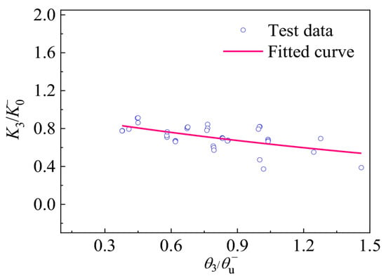
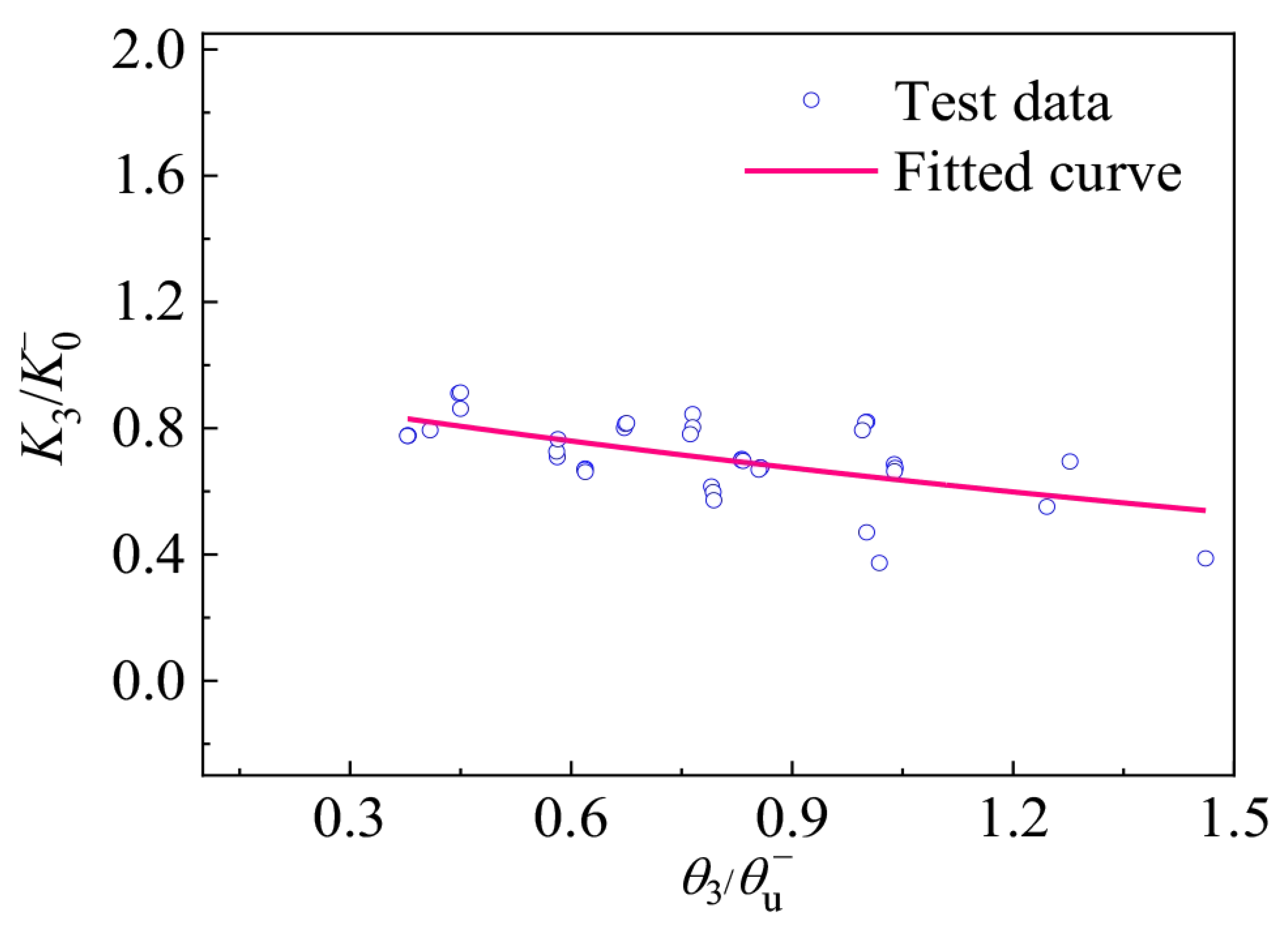
The degradation relationship of the negative unloading stiffness K3 was described by the relationship between K3/K0− and θ3/θu−. The unloading stiffness K3 was determined from the slope of the unloading branch between the negative reversal point (Point 3) and the zero-moment point (Point 4). The stiffness and rotation parameters were then normalized, and an exponential function was adopted to describe the degradation relationship. The fitted degradation curve of K3 is shown in Figure 18.
Figure 18.
Degradation relationship of negative unloading stiffness.
The degradation equation of K3 can be expressed as
(4) Degradation relationship of K4
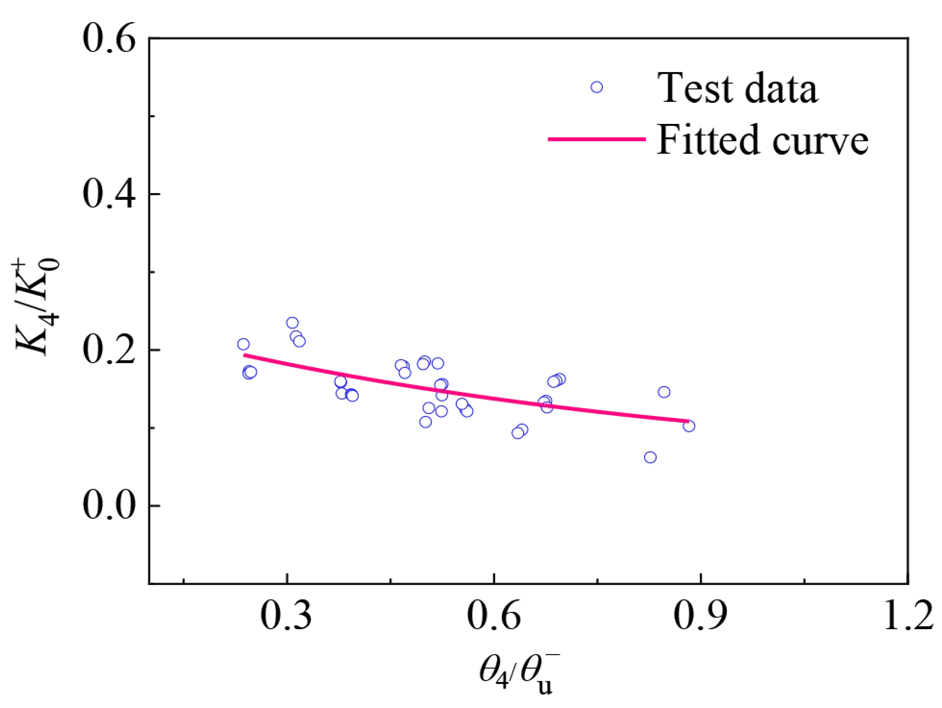
The degradation relationship of the positive reloading stiffness K4 was described by the relationship between K4/K0+ and θ4/θu−. The reloading stiffness K4 was determined from the slope of the reloading branch between the zero-moment point (Point 4) and the positive reversal point (Point 1). The stiffness and rotation parameters were then normalized, and an exponential function was adopted to describe the degradation relationship. The fitted degradation curve of K4 is shown in Figure 19.
Figure 19.
Degradation relationship of positive reloading stiffness.
The degradation equation of K4 can be expressed as
4.3. Hysteretic Rules and Calculation Procedure
The restoring force model developed in this study was established based on the experimentally observed moment–rotation response of the blind-bolted T-stub joints. The backbone curve was used to describe the evolution of moment resistance with increasing rotation, while the stiffness degradation relationships were introduced to characterize the unloading and reloading behavior under cyclic loading. The model therefore accounts for the principal nonlinear characteristics observed in the tests, including yielding, post-yield strengthening, strength degradation, and cyclic stiffness deterioration.
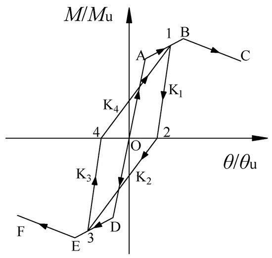
Based on the three-segment backbone curve, the stiffness degradation relationships, and the hysteretic path rules, the restoring force model shown in Figure 20 was established. Before yielding, the unloading path was assumed to coincide with the initial loading path, and the unloading stiffness was taken as the corresponding initial elastic stiffness. After yielding, the positive and negative unloading stiffnesses were determined using the degradation relationships of K1 and K3, respectively, while the reverse reloading stiffnesses were calculated using the corresponding relationships of K2 and K4.
Figure 20.
Restoring force model.
During load reversal, the reloading path was determined according to the previously reached deformation history. When the opposite loading direction had not yet reached yielding, the reloading path was directed toward the corresponding yield point of the backbone curve. After yielding had occurred in both loading directions, the reloading path was directed toward the previously reached maximum rotation point in the opposite direction. Once the reloading path reached the prescribed historical point or intersected the backbone curve, the response subsequently followed the corresponding backbone branch until the next unloading or reversal occurred. The same rules were applied to the subsequent loading cycles.
For clarity, the step-by-step calculation procedure of the proposed restoring force model is summarized as follows:
(1) Prescribe the rotation θi at the current loading step and determine the loading direction according to θi–θi−1.
(2) Determine whether the current response follows the backbone curve, unloading branch, or reverse reloading branch according to the loading history and the previously reached maximum positive and negative rotations.
(3) When a new maximum rotation is reached, calculate the corresponding moment Mi from the appropriate segment of the positive or negative backbone curve.
(4) When unloading occurs, calculate Mi using the corresponding unloading stiffness K1 or K3 and the coordinates of the unloading point.
(5) After load reversal, determine the target point in the opposite loading direction. If the opposite branch has not yet reached yielding, the corresponding yield point is adopted as the target. Otherwise, the previously reached maximum rotation point in that direction is used.
(6) Calculate Mi along the corresponding reloading branch using K2 or K4. When the reloading path reaches the prescribed historical point or intersects the backbone curve, switch to the corresponding backbone branch according to the hysteretic rules shown in Figure 20.
(7) Update Mi, θi, the loading direction, and the historical maximum positive and negative rotations, and repeat Steps (1)–(6) for the next rotation increment.
As an illustrative example, the first 0.050 rad loading cycle of specimen SBJ-T14 is considered. At θ = 0.050 rad, the response is located on the positive post-yield strengthening branch of the backbone curve, giving M = 101.55 kN·m. During unloading, the calculated positive unloading stiffness is K1 = 5821.37 kN·m/rad, resulting in a zero-moment point at (0.03256 rad, 0). During reverse loading, the path is directed toward the previously reached negative maximum rotation point from the preceding loading level (−0.034 rad, −80.99 kN·m) with a reloading stiffness of K2 = 1216.83 kN·m/rad, and subsequently reaches (−0.050 rad, −94.56 kN·m) along the negative backbone curve. The negative unloading stiffness is then calculated as K3 = 5989.30 kN·m/rad, giving the second zero-moment point at (−0.03421 rad, 0). The subsequent positive reloading branch is directed toward the previously reached positive maximum rotation point (0.034 rad, 82.94 kN·m) with K4 = 1215.96 kN·m/rad. The state variables are then updated, and the same procedure is repeated for the subsequent loading steps.
4.4. Model Validation
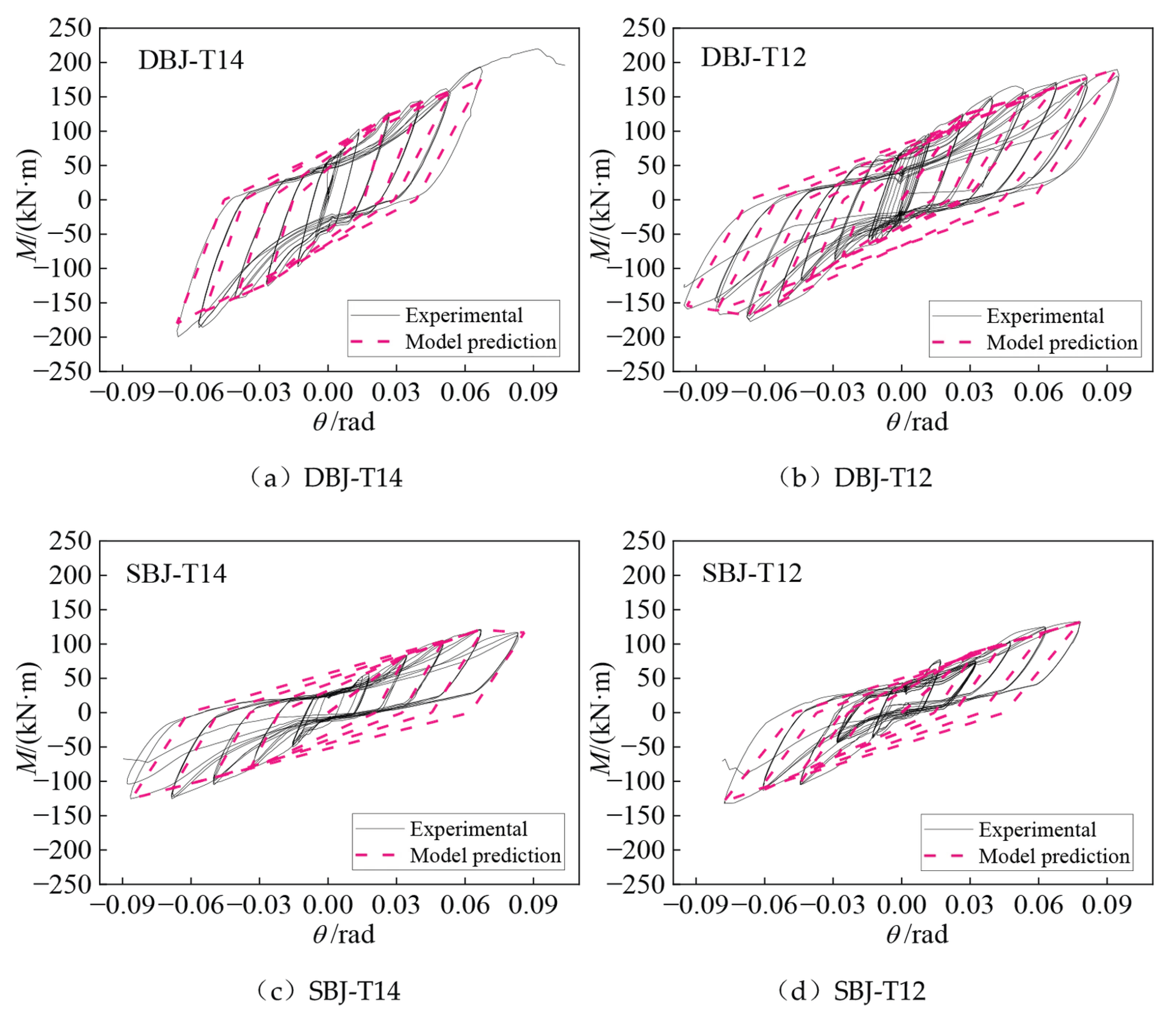
To evaluate the capability of the proposed restoring force model in reproducing the cyclic response of the blind-bolted T-stub joints, the calculated moment–rotation hysteretic curves were compared with the corresponding experimental results. Representative loading cycles covering the post-yield and large-deformation stages were selected for the four specimens. The pre-yield cycles were not separately considered because the model assumes that the unloading path coincides with the initial elastic loading path before yielding.
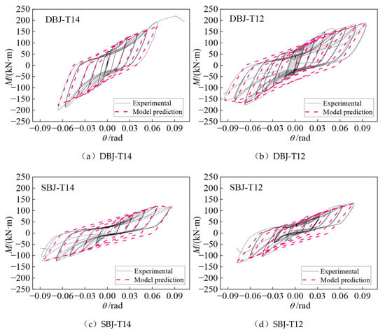
Figure 21 compares the calculated and experimental hysteretic responses of the four specimens. Overall, the proposed model reasonably reproduces the principal characteristics of the measured cyclic response, including the positive and negative moment levels, the degradation of unloading and reloading stiffness, the reverse-loading paths, and the progressive evolution of the hysteretic loops with increasing rotation amplitude. The agreement is generally better at small and moderate rotation levels, particularly during the yielding and strengthening stages. The calculated responses of DBJ-T12 show relatively good agreement with the experimental curves over most of the loading range, whereas larger local deviations are observed for DBJ-T14, SBJ-T14, and SBJ-T12 at large rotation amplitudes.
Figure 21.
Comparison between experimental and calculated hysteretic responses of the specimens.
At large deformation levels, the calculated hysteretic loops exhibit noticeable discrepancies from the experimental results in terms of loop fullness, unloading and reloading trajectories, and local strength degradation. These differences become more evident after pronounced slip, plastic deformation, and cracking have developed in the T-stub connection region. In the experiments, bolt slip, contact opening and closing, local yielding of the T-stub flange, and crack initiation and propagation occurred progressively and interacted with each other, resulting in irregular cycle-to-cycle variations in the hysteretic response. In contrast, the proposed model represents these effects through continuous stiffness degradation relationships and simplified piecewise-linear hysteretic rules. Consequently, the simplified model cannot accurately reproduce the sudden reduction in moment resistance associated with local T-stub fracture or the irregular hysteretic responses caused by accumulated damage. Therefore, the model is more suitable for describing the overall cyclic behavior before severe connection damage develops, while its predictions near fracture and at large rotations should be interpreted with caution.
Nevertheless, the model captures the overall hysteretic envelope, the principal stiffness degradation characteristics, and the asymmetric cyclic response of the four specimens. Considering its relatively simple formulation and the limited number of parameters required, the proposed model provides a reasonable macroscopic representation of the cyclic behavior of the investigated joints and can be used for nonlinear seismic response analysis within the deformation range covered by the present tests.
5. Discussion
Previous studies on SCTBs have mainly investigated welded joints and connections equipped with supplemental damping devices. Wu et al. [9] investigated all-welded irregular joints designed according to the strong-member–weak-joint principle. Their specimens exhibited shear deformation in the lower joint core region and cracking of the welds connecting the beam flanges to the column wall. Other studies introduced friction dampers and shape memory alloy (SMA) devices to improve the seismic performance of SCTB joints, with damage mainly concentrated in designated replaceable components [11,12,13]. In contrast, the present study adopted prefabricated blind-bolted T-stub connections to accommodate the special configurations of SCTB beam–column joints. The use of blind bolts and T-stubs provides a connection alternative to conventional on-site welding, particularly for closed-section columns where access for bolt tightening is limited. This arrangement can reduce the need for on-site welding and facilitate prefabricated assembly, which is of practical interest for traditional-style buildings constructed near protected historical sites. The experimental results showed that the main damage was concentrated at the T-stub flange–web junction, while the beams, columns, and joint core regions remained without obvious damage. The rotation ductility coefficients ranged from 2.27 to 3.96, indicating that the connections developed inelastic deformation before failure. Unlike welded SCTB joints, whose behavior may be governed by joint-core deformation or weld damage, the proposed connections accommodated most of the inelastic deformation through the T-stub components. Therefore, the significance of this study lies not only in the observed seismic performance but also in the development of a prefabricated connection arrangement suitable for the irregular beam–column joints of SCTBs.
The mechanical behavior of the proposed joints can be further understood by comparison with blind-bolted T-stub connections in other steel structures. Liu et al. [28] investigated steel and concrete-filled steel tubular column joints with blind-bolted T-stub connections under cyclic loading. Their specimens employed T-stub web and flange thicknesses of 9 and 14 mm, respectively, and thicker sections of 12 and 19 mm. The thinner T-stubs mainly failed by flange fracture, whereas the thicker connections exhibited severe column-wall buckling and blind-bolt pull-off. For the hollow steel column joints, increasing the T-stub thickness increased the load-carrying capacity by 23.3% and the plastic deformation capacity by 18.8%. Although both studies used blind-bolted T-stub connections and cyclic loading, the present joints were developed for the specific geometrical requirements of SCTBs. The connection system combined a closed circular hollow section column with H-section beams through T-stubs and blind bolts. Internal and external leveling plates were employed to accommodate the curved column surface and provide bearing interfaces for the bolted connection. In addition, internal stiffeners were provided to strengthen the column region. The T-stub flange and web thicknesses were limited to 12–14 mm and 8–9 mm, respectively, while the overall joint design followed the strong-column–weak-beam principle. Unlike the thicker specimens investigated by Liu et al., the four specimens in this study exhibited no obvious column-wall failure, and the dominant damage remained concentrated at the T-stub flange–web junction. This difference suggests that the relative resistance of the T-stubs, blind bolts, column wall, and stiffening components is important in determining the governing failure mode. The influence of T-stub thickness on rotation ductility was also different between loading directions. For DBJ-T14 and DBJ-T12, the positive ductility coefficients were 3.96 and 3.58, respectively, whereas the negative values were 2.44 and 3.39. The corresponding coefficients for SBJ-T14 and SBJ-T12 were 2.52 and 2.60 in the positive direction and 2.69 and 2.27 in the negative direction. These differences show that the deformation capacity of irregular SCTB joints depends not only on T-stub thickness but also on joint configuration and loading direction. Compared with the joints investigated by Liu et al., the present connections maintained a consistent T-stub-dominated failure mode within the investigated thickness range, providing experimental evidence for the influence of connection configuration on damage distribution.
Regarding restoring force modeling, Shen et al. [35] developed a four-stage multilinear cyclic envelope model for partially restrained bolted T-stub connections, including elastic, strengthening, post-peak softening, and residual resistance stages. Shen et al. [36] subsequently adopted the Pinching4 model and a surrogate-based calibration procedure to describe hysteretic behavior, including pinching and stiffness degradation. These studies provide important methods for characterizing the nonlinear cyclic response of conventional bolted T-stub connections. The present study focused on the restoring force behavior of prefabricated blind-bolted T-stub joints with irregular single- and double-beam configurations in SCTBs. The experimental skeleton curves showed three principal stages: elastic response, post-yield strengthening, and post-peak degradation. In particular, the post-peak descending branches were relatively short for several loading directions because the moment resistance decreased rapidly after significant cracking and fracture developed at the T-stub flange–web junction. Based on these characteristics, a normalized trilinear backbone curve was adopted to represent the main stages of the moment–rotation response. Although the four specimens exhibited different moment resistances and rotation capacities, their normalized skeleton curves showed similar overall trends. The model further incorporated four unloading and reloading stiffness degradation relationships and loading-history-dependent hysteretic path rules to reproduce the asymmetric cyclic responses. Unlike the cyclic envelope model developed by Shen et al. [35], the proposed model describes both the backbone response and the unloading-reloading paths. Compared with the Pinching4-based approach [36], the present model uses directly fitted stiffness relationships and explicit hysteretic path rules, although it does not represent all local pinching and damage effects in the same detail. The contribution of this study is therefore to establish an experimentally based restoring force model for the specific prefabricated joint configurations of SCTBs, rather than to propose a fundamentally new hysteretic theory. The model provides a basis for incorporating the nonlinear joint response into seismic analysis of SCTBs. However, the investigated connections mainly differ from the irregular joint configurations of SCTBs, which involve special geometric requirements, single- and double-beam arrangements, and complex load-transfer paths. Restoring force models specifically developed for blind-bolted T-stub joints in SCTBs remain limited.
6. Conclusions
Based on the low-cycle reversed loading tests and restoring force modeling of four T-stub joints with blind bolts for SCTBs, the following conclusions can be drawn:
(1) Damage of all four specimens was mainly concentrated in the T-stub connection region. With increasing loading amplitude, bolt slip, opening between the T-stub flanges and leveling plates, and bending deformation of the T-stub flanges gradually developed. Cracks subsequently initiated and propagated at the T-stub flange–web junction, which eventually governed the failure of the joints. No obvious damage was observed in the columns or joint core regions, indicating that the major inelastic deformation was confined to the connection components.
(2) The specimens exhibited generally stable spindle-shaped hysteretic responses. The hysteretic loops became progressively fuller after yielding, while a certain degree of pinching remained because the cyclic deformation was mainly accommodated by the T-stub connections rather than by plastic hinging at the beam ends. The double-beam specimens DBJ-T14 and DBJ-T12 exhibited fuller hysteretic loops and larger enclosed areas than the single-beam specimens SBJ-T14 and SBJ-T12, owing to the participation of a larger number of T-stub components in moment transfer and cyclic deformation.
(3) The skeleton curves of the four specimens showed similar overall development and could be divided into three stages: elastic response, post-yield strengthening, and post-peak degradation. The differences among the specimens were mainly associated with the dimensions and number of T-stub components. Increasing the T-stub thickness enhanced the joint moment resistance, while the double-beam configuration provided higher overall load-carrying capacity than the corresponding single-beam configuration. After normalization, the four skeleton curves exhibited similar trends, which formed the basis for establishing a unified three-segment backbone curve.
(4) The unloading and reloading stiffnesses degraded progressively with increasing cyclic deformation. Four characteristic stiffness parameters were introduced to describe the positive unloading, negative reloading, negative unloading, and positive reloading branches, respectively. The normalized stiffness data exhibited clear nonlinear degradation trends, and the corresponding regression relationships provided a continuous description of stiffness deterioration during cyclic loading.
(5) A restoring force model was established by combining the normalized three-segment backbone curve, the stiffness degradation relationships, and the hysteretic path rules. Comparison with the experimental moment–rotation hysteretic curves showed that the model reasonably reproduced the overall loop shape, positive and negative peak responses, stiffness degradation, reverse-loading paths, and asymmetric cyclic behavior of the four specimens. Larger discrepancies occurred at large rotation amplitudes because local slip, contact opening and closing, crack propagation, and accumulated damage could not be fully represented by the simplified model. Within the deformation range covered by the present tests, the proposed model provides a practical representation of the cyclic behavior of this type of joint and can be used for nonlinear seismic response analysis of SCTBs.
The proposed blind-bolted T-stub connection provides a prefabricated solution for irregular beam–column joints in SCTBs, reducing the need for on-site welding. The concentration of damage in the T-stub components indicates their potential for localized replacement, while the proposed restoring force model provides a basis for nonlinear seismic analysis of SCTBs. Further studies should investigate the effects of connection parameters on seismic performance and validate the restoring force model using additional experimental data. The seismic behavior of complete SCTB frames and the replaceability of damaged T-stub components also require further investigation.
Author Contributions
Conceptualization, Z.W.; methodology, J.D.; writing—original draft preparation, Z.W. and X.Z.; writing—review and editing, J.D.; software, J.D.; supervision, H.S. and Q.H.; project administration, H.S.; funding acquisition, Q.H. All authors have read and agreed to the published version of the manuscript.
Funding
This work was supported by the National Natural Science Foundation of China (Grant No. 52008330), the Natural Science Foundation of Henan Province (Grant No. 252300421260), and the Joint Fund for Science and Technology Research Projects of Henan Province (Grant No. 252103810049). This work was also supported by the Major Science and Technology Program of Hainan Province (Grant No. ZDKJ201803) and the Postgraduate Education Reform and Quality Improvement Project of Henan Province (Grant Nos. YJS2025YBGZZ50 and YJS2026YBGZZ53).
Data Availability Statement
All data used to support the findings of this study are included within the article.
Conflicts of Interest
Author Lin Zhang was employed by Shanghai Municipal Engineering Design Institute (Group) Co., Ltd. The remaining authors declare that the research was conducted in the absence of any commercial or financial relationships that could be construed as a potential conflict of interest.
References
- Sha, B.; Xie, L.; Yong, X.; Li, A. An experimental study of the combined hysteretic behavior of dougong and upper frame in Yingxian Wood Pagoda. Constr. Build. Mater. 2021, 305, 124723. [Google Scholar] [CrossRef] [Scilit]
- Qi, L.J.; Cao, Y.; Xue, J.Y.; Yuan, Z.; Ling, H.Q.; Meng, R.F. Seismic performance evaluation and engineering application of modern Chinese traditional-style buildings: State-of-the-art review. Structures 2023, 56, 105022. [Google Scholar] [CrossRef] [Scilit]
- Qi, L.J.; Xue, J.Y. Pseudo-dynamic test and time-history analyses of traditional-style steel frame structures. Int. J. Steel Struct. 2018, 18, 402–416. [Google Scholar] [CrossRef] [Scilit]
- Qi, L.J.; Xue, J.Y.; Leon, R.T. Experimental and analytical investigation of transition steel connections in traditional-style buildings. Eng. Struct. 2017, 150, 438–450. [Google Scholar] [CrossRef] [Scilit]
- Xue, J.Y.; Qi, L.J.; Yang, K.; Wu, Z.J. Dynamic experimental study on single- and double-beam column joints in steel traditional-style buildings. Struct. Eng. Mech. 2017, 63, 617–628. [Google Scholar]
- Xue, J.Y.; Ma, L.L.; Wu, Z.J. Seismic performance of steel joints between double beams and columns in Chinese traditional-style buildings. Int. J. Steel Struct. 2018, 18, 417–432. [Google Scholar] [CrossRef] [Scilit]
- Xue, J.Y.; Wu, Z.J.; Sui, Y.; Ge, H.; Wu, K. Experimental study and numerical analysis on aseismic performance of steel double-beams-column interior-joints in traditional style building. Eng. Mech. 2016, 33, 97–105. [Google Scholar]
- Xue, J.Y.; Wu, Z.J.; Sui, Y.; Liu, Z. Experimental study on seismic performance of steel double-beams column exterior joints in antique style building. J. Build. Struct. 2015, 36, 80–89. [Google Scholar]
- Wu, Z.; Wang, X.; Bu, X.; Dong, J. Design and Shear Bearing Capacity Calculation of All-Welded Irregular Joints in Steel Traditional Chinese Buildings. Buildings 2025, 15, 184. [Google Scholar] [CrossRef] [Scilit]
- Qi, L.J.; Xue, J.Y.; Sui, Y.; Wu, Z.J. Smart retrofitting of irregular steel joints in traditional Chinese buildings using viscous dampers. Eng. Struct. 2021, 228, 111526. [Google Scholar] [CrossRef] [Scilit]
- Yuan, Z.; Qi, L.J.; Xue, J.Y. Seismic performance of steel semi-rigid friction-damped joints with replaceable angles in modern Chinese traditional-style buildings. J. Constr. Steel Res. 2023, 207, 107948. [Google Scholar] [CrossRef] [Scilit]
- Yuan, Z.; Qi, L.J.; Xue, G.M.; Xue, J.Y. Resilient joints with SMA bar-shear friction damper devices in modern Chinese traditional-style steel buildings: Seismic performance evaluation and optimized design. J. Build. Eng. 2024, 82, 108300. [Google Scholar] [CrossRef] [Scilit]
- Qi, L.J.; Yuan, Z.; Xue, J.Y. Experimental and numerical study on seismic performance of steel semi-rigid joints equipped with SMA bars and friction dampers. Eng. Struct. 2024, 301, 117320. [Google Scholar] [CrossRef] [Scilit]
- Men, J.; Li, T.; Zhou, Q.; Zhang, H.; Huang, C.H. Structural fuse performance and earthquake-resilient performance of beam-column joints with replaceable T-stub. J. Constr. Steel Res. 2023, 206, 107943. [Google Scholar] [CrossRef] [Scilit]
- Li, T.; Men, J.; Zhang, Q.; Li, J.; Huang, C.H. Seismic fragility and resilience assessment of steel frame with replaceable T-stub connection components. Eng. Struct. 2024, 314, 118396. [Google Scholar] [CrossRef] [Scilit]
- Lee, J.; Goldsworthy, H.M.; Gad, E.F. Blind bolted T-stub connections to unfilled hollow section columns in low rise structures. J. Constr. Steel Res. 2010, 66, 981–992. [Google Scholar] [CrossRef] [Scilit]
- Lee, J.; Goldsworthy, H.M.; Gad, E.F. Blind bolted moment connection to unfilled hollow section columns using extended T-stub with back face support. Eng. Struct. 2011, 33, 1710–1722. [Google Scholar] [CrossRef] [Scilit]
- Tizani, W.; Wang, Z.; Hajirasouliha, I. Hysteretic performance of a new blind bolted connection to concrete filled columns under cyclic loading: An experimental investigation. Eng. Struct. 2013, 46, 535–546. [Google Scholar] [CrossRef] [Scilit]
- Pitrakkos, T.; Tizani, W. Experimental behaviour of a novel anchored blind-bolt in tension. Eng. Struct. 2013, 49, 905–919. [Google Scholar] [CrossRef] [Scilit]
- Liu, M.; Zhu, X.; Wang, P.; Tuoya, W.; Hu, S. Tension strength and design method for thread-fixed one-side bolted T-stub. Eng. Struct. 2017, 150, 918–933. [Google Scholar] [CrossRef] [Scilit]
- Zhang, Y.; Liu, M.; Ma, Q.; Liu, Z.; Wang, P.; Ma, C.; Sun, L. Yield line patterns of T-stubs connected by thread-fixed one-side bolts under tension. J. Constr. Steel Res. 2020, 166, 105932. [Google Scholar] [CrossRef] [Scilit]
- Liu, Y.; Sun, L.; Zhang, Y.; Liu, L.; Liu, M.; Wang, P.; Zhang, W. Proposed analytical models for bolted T-stubs to square hollow section column connection using thread-fixed one-side bolts under tension. J. Build. Eng. 2022, 52, 104398. [Google Scholar] [CrossRef] [Scilit]
- Cabrera, M.; Tizani, W.; Mahmood, M.; Shamsudin, M.F. Analysis of Extended Hollo-Bolt connections: Combined failure in tension. J. Constr. Steel Res. 2020, 165, 105766. [Google Scholar] [CrossRef] [Scilit]
- Wang, W.; Li, M.; Chen, Y.; Jian, X. Cyclic behavior of endplate connections to tubular columns with novel slip-critical blind bolts. Eng. Struct. 2017, 148, 949–962. [Google Scholar] [CrossRef] [Scilit]
- Gao, X.; Wang, W.; Teh, L.H.; Zhuang, L. A novel slip-critical blind bolt: Experimental studies on shear, tensile and combined tensile-shear resistances. Thin-Walled Struct. 2022, 170, 108630. [Google Scholar] [CrossRef] [Scilit]
- Jiao, W.; Wang, W.; Chen, Y.; Teh, L.H. Seismic performance of concrete-filled SHS column-to-beam connections with slip-critical blind bolts. J. Constr. Steel Res. 2020, 170, 106075. [Google Scholar] [CrossRef] [Scilit]
- Gao, X.; Wang, W.; Teh, L.H. Experimental and numerical investigations of tensile behavior of slip-critical blind bolts anchored in concrete-filled steel tubes. Structures 2023, 55, 354–369. [Google Scholar] [CrossRef] [Scilit]
- Liu, H.; Yan, S.; Wang, X.; Zhang, J.; Lin, Y. Experimental study on the seismic damage behavior of composite joints of concrete-filled steel tube column with blind bolts. Structures 2024, 70, 107767. [Google Scholar] [CrossRef] [Scilit]
- Xiao, S.; Bu, X.; Chen, Y.; Wang, X. Investigating the damage-based seismic performance of the blind bolt-connected steel framework. Structures 2024, 69, 107388. [Google Scholar] [CrossRef] [Scilit]
- Zhang, Y.F.; Zhang, J.H.; Demoha, K. Further analysis on mechanical behaviors of blind-bolted T-stub connections to CFDST columns. Structures 2023, 48, 1964–1976. [Google Scholar] [CrossRef] [Scilit]
- Han, X.Z.; Chan, T.M. Tensile behaviour of swift-constructed demountable blind bolted T-stub to hollow section column connection. Eng. Struct. 2025, 336, 120086. [Google Scholar] [CrossRef] [Scilit]
- Bu, X.; Xiao, S.; Wu, Z.; Li, X.; Wang, X. Damage Evaluation of T-Stub Connected to Hollow Section Column Using Blind Bolts under Tension. Buildings 2023, 13, 2603. [Google Scholar] [CrossRef] [Scilit]
- Liu, H.; Yan, S.; Wang, X.; Chen, Y.; Li, Y. Seismic Performance Analysis of Middle Column Joints with T-Stub Steel Connections Considering Cumulative Damage. Buildings 2025, 15, 1429. [Google Scholar] [CrossRef] [Scilit]
- Fan, J.; Zhao, J. Moment-rotation model of composite connection with curved endplate and blind bolts. J. Constr. Steel Res. 2021, 185, 106840. [Google Scholar] [CrossRef] [Scilit]
- Shen, Y.; Li, M.; Li, Y. A reliable cyclic envelope model for partially-restrained steel beam-column bolted T-stub connections based on experimental data. Thin-Walled Struct. 2024, 200, 111951. [Google Scholar] [CrossRef] [Scilit]
- Shen, Y.; Li, M.; Li, Y. Surrogate-based calibration and prediction of hysteretic model parameters for steel beam-column bolted T-stub connections. J. Build. Eng. 2025, 103, 112082. [Google Scholar] [CrossRef] [Scilit]
- Li, J. The Construction Method; Commercial Press: Shanghai, China, 1932. [Google Scholar]
- GB 50017-2017; Standard for Design of Steel Structures. Ministry of Housing and Urban-Rural Development of the People’s Republic of China: Beijing, China, 2017.
- JGJ 82-2011; Technical Specification for High Strength Bolt Connections of Steel Structures. Ministry of Housing and Urban-Rural Development of the People’s Republic of China: Beijing, China, 2011.
- GB/T 228.1-2021; Metallic Materials-Tensile Testing-Part 1: Method of Test at Room Temperature. Standardization Administration of the People’s Republic of China: Beijing, China, 2021.
- Işık, E.; Özdemir, M. Performance Based Assessment of Steel Frame Structures by Different Material Models. Int. J. Steel Struct. 2017, 17, 1021–1031. [Google Scholar] [CrossRef] [Scilit]

Disclaimer/Publisher’s Note: The statements, opinions and data contained in all publications are solely those of the individual author(s) and contributor(s) and not of MDPI and/or the editor(s). MDPI and/or the editor(s) disclaim responsibility for any injury to people or property resulting from any ideas, methods, instructions or products referred to in the content. |
© 2026 by the authors. Licensee MDPI, Basel, Switzerland. This article is an open access article distributed under the terms and conditions of the Creative Commons Attribution (CC BY) license.