


Abstract
This study investigates the early-age performance of large-area C30 concrete slabs under different curing regimes using a multi-scale approach combining laboratory experiments, field monitoring, and numerical simulation. The experimental results indicated that standard curing (SC7) maximized the mechanical properties. In contrast, the thermal insulation and moisture retention curing (TC) regime significantly reduced temperature gradients and stress mutation amplitudes by 42% compared to wet curing (WC) by leveraging the synergistic effect of aluminum foil and insulating cotton. This makes TC a preferred solution in situations where engineering constraints apply. Field monitoring demonstrated that WC is suitable for humidity-sensitive scenarios with low-temperature control requirements, while TC is more suitable for large-area concrete or low-temperature environments, balancing early strength development and long-term durability. This multi-field coupled model exhibits significant deviations during the early stage (0–7 days) due to complex boundary interactions, but achieves high quantitative accuracy in the long-term steady state (after 14 days), with a maximum error below 8%. The analysis revealed that the key driving factors for stress evolution are early hydration heat–humidity coupling and mid-term boundary transient switching. The study provides a novel, multi-scale validated curing optimization path for crack control in large-area concrete slabs.
1. Introduction
Against the backdrop of China’s urbanization rate exceeding 60% [1,2,3], and the trend of super high-rise and large-span public buildings developing towards “higher, larger, and thinner” structures [4,5], large-area cast-in-place concrete slabs have become a preferred choice due to their excellent performance [6,7]. However, these structures are susceptible to the influence of hydration heat, thermo-hygric exchange, and restraint systems during their early age, leading to temperature and humidity gradients that generate tensile stresses [8,9,10]. Stress concentration is a critical factor in crack formation [11]. When tensile stresses induced by these gradients exceed the real-time tensile strength of the concrete, visible cracks may appear within 24 h of pouring, developing into a network of through-cracks within 3 to 7 days [10,12]. These cracks provide pathways for corrosive substances such as CO2, Cl−, and SO42− to penetrate, which accelerates the depassivation and corrosion of the rebar, thereby weakening the structure’s durability [13,14,15], but also exacerbate the stack effect in high-rise buildings due to reduced floor airtightness, leading to increased energy consumption [16,17,18], and even triggering user complaints and legal disputes [19]. Therefore, in-depth research on the early-age cracking of large-area concrete slabs is of significant practical importance and urgency.
Numerous scholars have conducted extensive research on the issue of early-age cracking in concrete. These studies primarily focus on the compositional design of concrete materials [20,21,22], the optimization of construction techniques [23], and the detection and repair of cracks [24,25,26,27]. Mehran et al. [22] found that the inclusion of glass and nylon fibers in concrete bridge decks improved the mechanical properties of the concrete and reduced the formation of early microcracks. Wang et al. [28] suggest that the combined use of volcanic ash and cementitious materials has complementary and synergistic effects, which can enhance the hydration process of concrete, thereby improving the volume stability and crack resistance. Kumar et al. [24] demonstrated that automated systems employing image processing techniques such as edge detection, filtering, and machine learning algorithms can accurately identify cracks in concrete structures, assess their characteristics, and provide quantitative data for structural analysis. However, environmental conditions also significantly influence the early hydration characteristics of concrete, specifically the curing regimen. While numerous studies have examined curing effects under controlled laboratory conditions, research that integrates multi-scale methodologies, including in situ structural monitoring and field-validated numerical simulation, to systematically evaluate curing regimes on large-area concrete slabs, remains notably scarce [29,30,31,32]. Unreasonable curing regimes, such as excessively high or low curing temperatures, insufficient curing humidity, or excessively short curing times, can lead to the deterioration of early-age concrete performance and increase the risk of cracking [33,34,35]. Therefore, it is necessary to systematically study the influence of different curing regimes on the early-age performance of large-area concrete slabs.
With the rapid advancement of computer technology, multi-physics-coupled numerical simulation methods have become increasingly sophisticated, providing powerful tools for predicting the early-age behavior of concrete structures [36,37,38]. Concurrently, the development of distributed sensing technologies offers a convenient means of acquiring information such as temperature [39,40], humidity [41,42], and strain [43,44] within concrete structures. However, existing numerical simulation methods typically involve simplifications during the calculation process. For instance, concrete may be treated as a homogeneous material [45], the computational model may be simplified [46], or boundary conditions may be oversimplified [47]. These simplifications lead to substantial discrepancies between the simulation results and actual measured data [48]. Furthermore, current research inadequately addresses the dynamic impact of events such as curing and formwork removal on the early-age behavior of concrete, making it difficult to accurately predict cracking risks [49,50]. Therefore, it is necessary to develop more refined multi-physics-coupled numerical models that consider a greater number of influencing factors and are validated with measured data to enhance prediction accuracy and reliability.
This study takes the cast-in-place floor slab of a super high-rise apartment on Zhenwu Road in Taiyuan City as the experimental object. Employing a multi-scale research framework that integrates “indoor material experiments, on-site structural monitoring, and multi-field coupled simulations,” the study systematically assesses the impact of four different curing regimes on the early-age mechanical properties, temperature and humidity evolution, and stress fields of C30 concrete. Furthermore, a three-dimensional, fully coupled thermo-hydro-mechanical model is developed based on the COMSOL multi-physics platform. This model considers Knudsen diffusion, hydration, heat-induced time-varying elastic modulus, and transient boundary switching. The aim of this research is to establish a comparative system featuring a triple verification chain encompassing field measurements, laboratory testing, and numerical simulation, and to provide a theoretical basis and technical pathways for establishing a scientific and quantitative crack control system for concrete slabs.
2. Materials and Methods
2.1. Raw Materials and Mix Proportions
2.1.1. Cementitious Material
P·O 42.5 grade ordinary Portland cement produced by Shanxi Jinhu Cement Co., Ltd. was used in this study. Class III fly ash was obtained from Datang Taiyuan Second Thermal Power Plant (Taiyuan, China), exhibiting a fineness of 31.4% residue on a 45 μm sieve. Ground, granulated, blast furnace slag (S95 grade) was supplied by Shanxi Zhongke Slag Micro Powder Products Co., Ltd. (Lvliang, China), with a density of 2.89 g/cm3 and specific surface area of 412 m2/kg. The silica fume produced by Jinguilang Technology Co. Ltd. (Taiyuan, China) has a specific surface area of 15–30 m2/g.
2.1.2. Aggregate
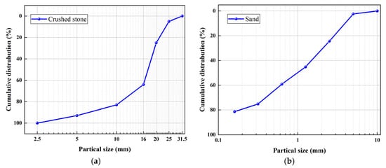
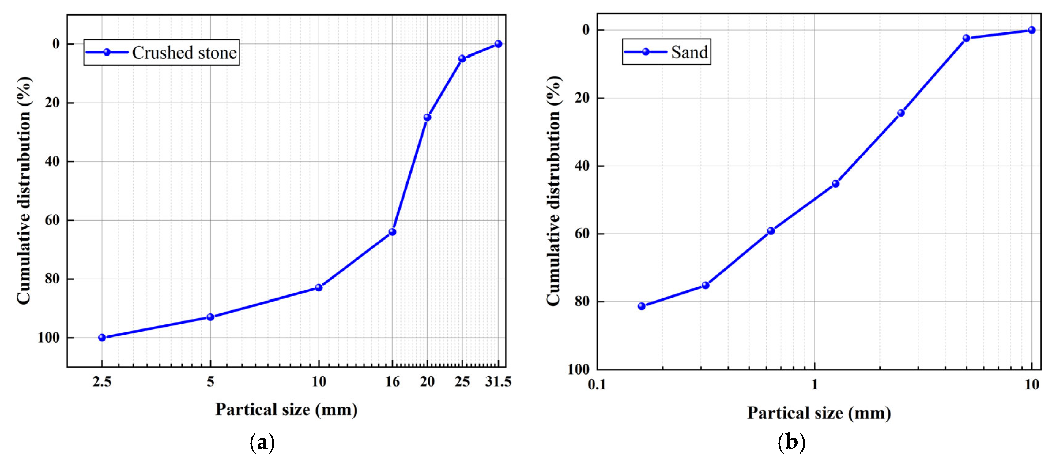
Crushed stone with continuous gradation of 5–25 mm was used, with the particle size distribution shown in Figure 1a. Medium sand with a fineness modulus of 2.8 was employed, the grain size distribution of which is presented in Figure 1b.
Figure 1.
Particle size of aggregate. (a) Crushed stone, and (b) sand.
2.1.3. Chemical Admixtures
A polycarboxylate-based high-range water-reducing admixture (HRWR) produced by Shanxi Rongqida Concrete Technology Co., Ltd. (Taiyuan, China), was employed, exhibiting a water reduction rate of 38%, density of 1.092 g/cm3, and pH value of 6.0.
2.1.4. Mix Proportion Design
This mix design is identical to that used in the structural concrete of Building 9 at the Zhenwu Road Commercial Complex project in Taiyuan. The water-to-binder ratio was maintained at 0.51, with a sand-to-aggregate ratio of 50% and an apparent density of 2350 kg/m3. The selected C30 concrete mix design was determined based on the Chinese standards JGJ 3–2010 [51] and the commonly used mix proportions for standard floor slabs in multiple typical super high-rise projects. The detailed mix proportions are presented in Table 1.
Table 1.
Proportioning of C30 concrete (kg/m3).
2.2. Specimen Preparation and Testing
2.2.1. Curing Regimens
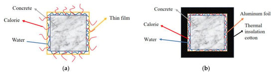
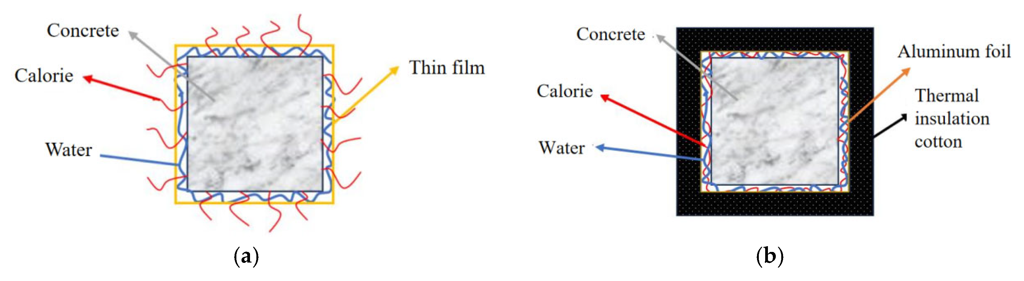
This study employed four distinct curing methods: ① standard curing for 7 days (SC7); ② standard curing for 3 days followed by natural curing for 4 days (SC3 + NC4); ③ wet curing for 3 days followed by natural curing for 4 days (WC3 + NC4); and ④ thermal and moisture-retaining curing for 3 days followed by natural curing for 4 days (TC3 + NC4). During the test period, the average daytime temperature was 33.5 °C, the average nighttime temperature was 22 °C, the relative humidity was 54%, and the average wind speed was 2.2 m/s. The schematic diagrams for wet curing, and thermal and moisture-retaining curing are shown in Figure 2. The detailed group assignments are shown in Table 2.
Figure 2.
The schematic diagrams for wet curing and thermal and moisture-retaining curing. (a) Wet curing and (b) thermal and moisture-retaining curing.
Table 2.
Maintenance methods.
The plastic film employed in SC and WC is manufactured by Fujian FuMao Construction Engineering Co., Ltd. (Fuzhou, China). This film features selective vapor permeability, achieving an effective water retention rate of ≥95%, effectively blocking water vapor migration while facilitating heat exchange. The thermal insulation cotton with the surface-adhered aluminum foil paper used in TC is also produced by Fujian FuMao Construction Engineering Co., Ltd., with a thermal conductivity of 0.032 W/(m·K). This material achieves complete isolation via the aluminum foil layer, simultaneously preventing heat and moisture transfer.
2.2.2. Specimen Preparation
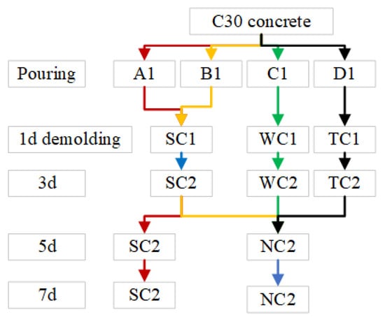
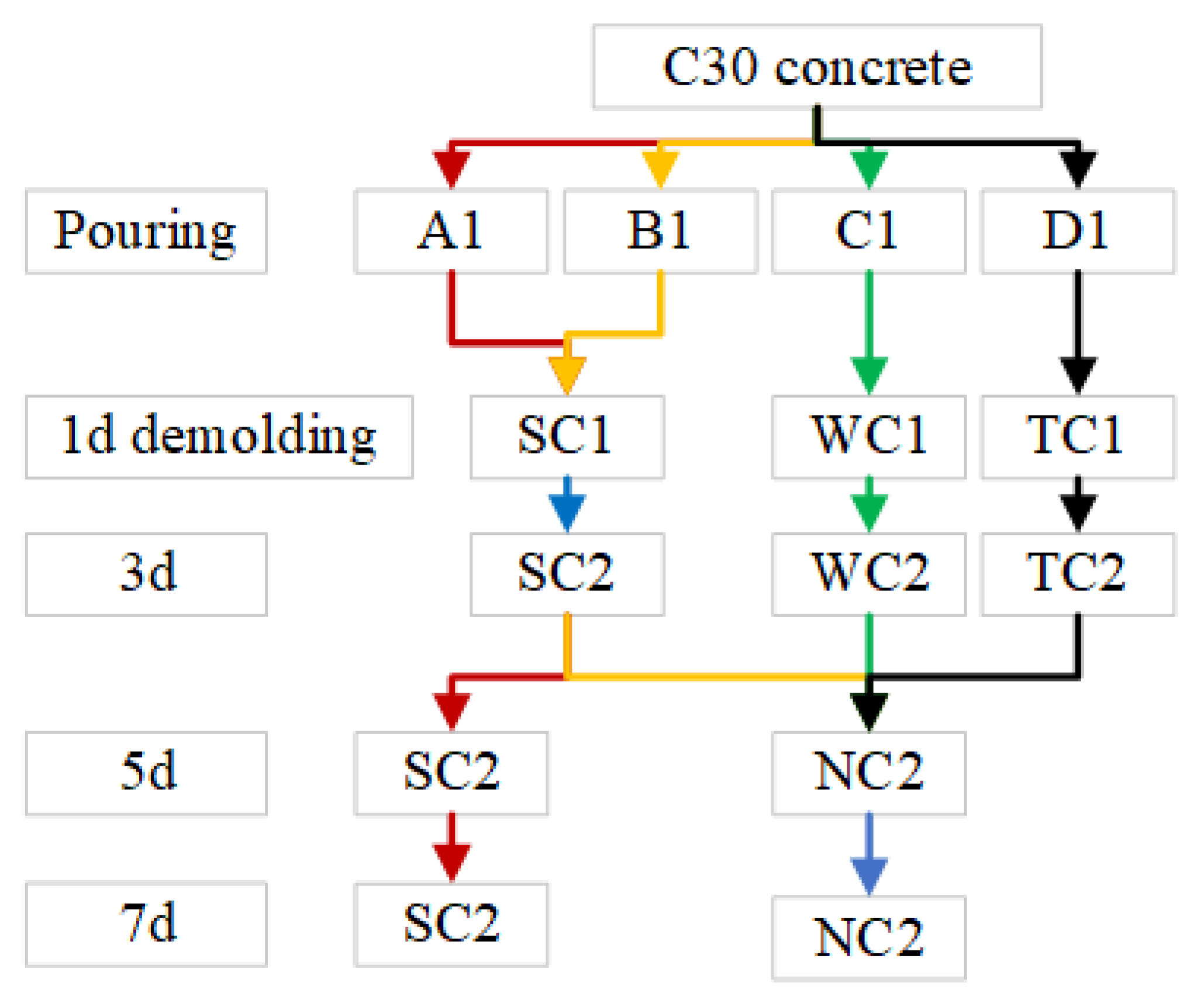
In this study, C30 concrete was supplied directly by a ready-mix plant. After casting into standard molds, the specimens were compacted on a vibrating table. Post molding, Group A1 and B1 specimens were surface-covered with plastic film; Group C1 (with molds) was fully wrapped in pre-laid plastic film, and Group D1 (with molds) was placed on aluminum foil–lined insulation cotton and tightly enveloped using wooden boards to ensure close contact. All specimens remained in a constant-temperature room for 24 h before demolding.
After demolding, the curing protocols diverged: Groups A1 and B1 underwent standard curing in saturated Ca(OH)2 solution at 20 ± 2 °C; B1 was moved outdoors for 3 days. Group C1 continued moisture curing, remaining wrapped in plastic film, while Group D1 maintained its aluminum foil–insulation cotton wrapping for combined thermal–moisture curing. All group samples were moved outdoors on Day 5 for a 2-day outdoor curing period, as detailed in Figure 3.
Figure 3.
Test block curing process.
2.2.3. Mechanical Performance Testing
Mechanical performance testing was conducted using a DYE-2000S fully automatic constant stress testing machine (Hebei Huaxi Building Material Testing Instrument Co., Ltd., Cangzhou, China). In accordance with the Chinese standard GB/T 50081-2019 [52], 100 mm cube specimens were used to determine compressive strength and splitting tensile strength, while 150 mm × 150 mm × 300 mm prism specimens were used to test the modulus of elasticity. All test data were averaged from three parallel tests to ensure the reliability of the results.
2.3. Field Monitoring Scheme
2.3.1. Field Setup
This study is based on the 19th-floor top slab of Building 9 in the Zhenwu Road project in Taiyuan City. Two slabs of identical dimensions from the same floor were selected. Each slab has a thickness of 150 mm, a length of 8300 mm, and a width of 5100 mm. Two different curing regimes, WC and TC, were employed, with the film removed at 3 days and the bottom mold dismantled at 15 days.
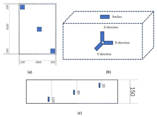
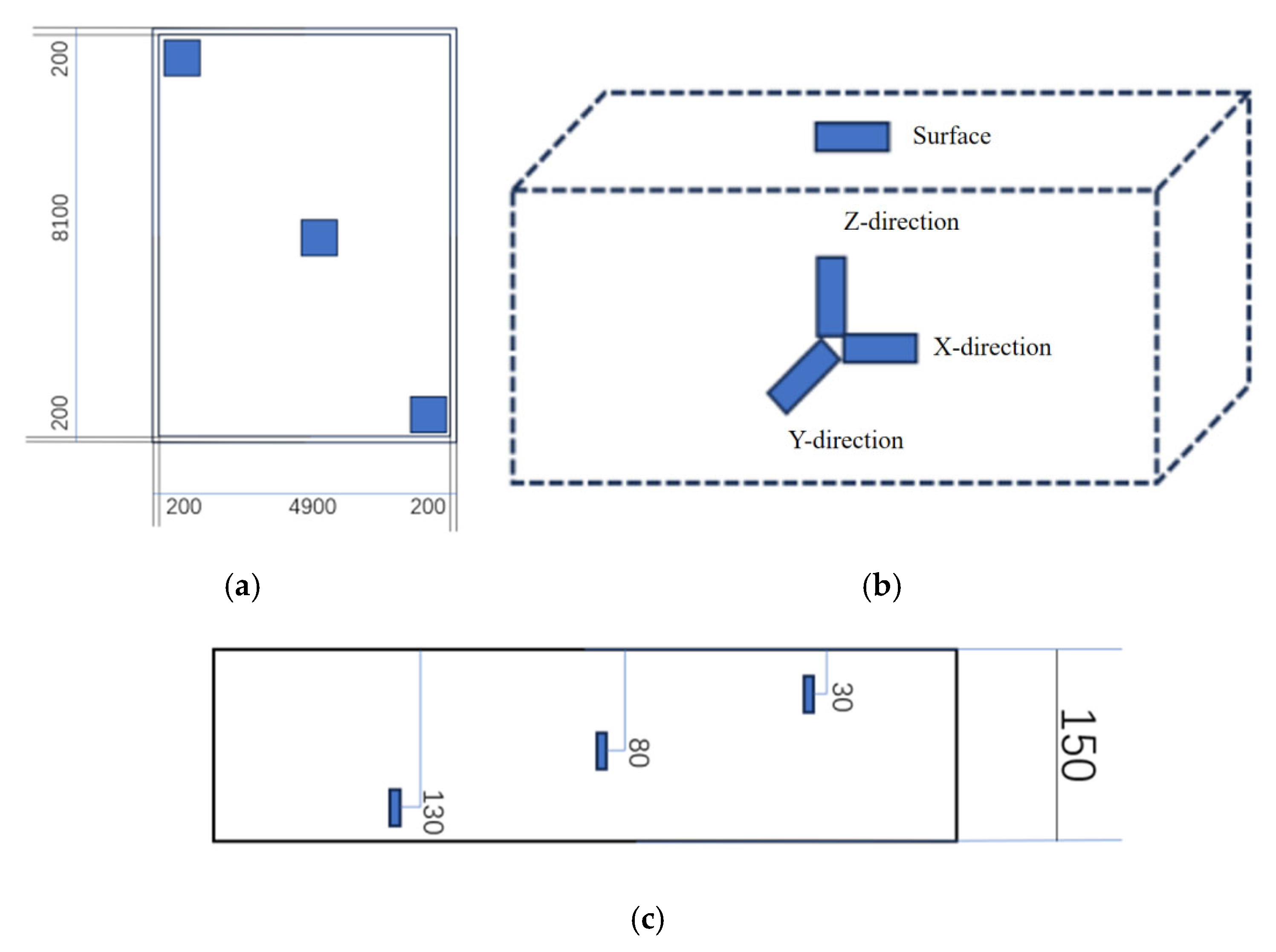
Prior to concrete pouring, a 1 m × 1 m monitoring area was established at the center of each test region to deploy a three-dimensional monitoring system consisting of thermistor sensors, PVC humidity test tubes, and vibrating wire strain gauges. The layout of the test regions is shown in Figure 4a. The arrangement depths of the thermistor sensors and PVC tubes in the top slab were 30 mm, 80 mm, and 130 mm from the concrete surface, as illustrated in Figure 4c. At the central position of the monitoring area, embedded vibrating wire strain gauges were installed along the X (east–west), Y (north–south), and Z (vertical) directions. Additionally, surface-vibrating wire strain gauges were installed on the corresponding surface of the monitoring area 24 h after concrete pouring, as depicted in Figure 4b.
Figure 4.
Schematic diagram of survey area and mode. (a) Survey area, (b) the depth of strain gauge embedding, and (c) the burial depth of thermistor and PVC pipe.
2.3.2. Data Processing
Temperature and humidity data from three test zones at three depths were arithmetically averaged by depth to represent the slab conditions at each age. Similarly, strain measurements—collected internally in three orthogonal directions and on the surface across the zones—were averaged by direction (including surface) to estimate the representative strain values for the slab.
Thermal stress is generated in an object when temperature changes are prevented from causing free expansion or contraction, or when there is an uneven internal temperature distribution [53,54]. This stress arises from two primary causes: (1) restricted structural expansion or contraction due to temperature variations, and (2) differences in the thermal expansion coefficients of constituent materials. The uniaxial thermal stress is calculated using Equation (1):
where σT is the thermal stress, εmeans is the total strain measured by the embedded or surface-mounted strain gauge, EC is the modulus of elasticity, β is the coefficient of linear expansion of the strain gauge steel wire, α is the coefficient of linear expansion, and ∆T is the temperature change.
In this study, the concrete slab experiences elastic constraints from internal reinforcement and surrounding beams in the X and Y directions, and from reinforcement alone in the Z direction, inducing triaxial thermal stress. Thus, uniaxial thermal stress theory is extended to a triaxial state. In this model, the concrete is treated as a continuum of microscopic cubic elements, each small enough to have a uniform temperature. In the absence of constraints, these elements undergo only free thermal deformation without stress. Under actual boundary conditions, however, total strain comprises both free thermal strain and additional constrained strain, leading to stress development. Therefore, in the absence of external constraints, each element undergoes free thermal deformation. The free thermal strain components in the three principal directions exhibit isotropy, with their expressions given by Equation (2), as follows:
where εth is the thermal strain component.
According to Hooke’s Law, the total deformation components within the concrete cube are obtained as follows:
Equations (3)–(5) represent the thermal stress field within the concrete structure, based on which the thermal stress of the concrete structure can be calculated:
Equation (6) establishes a calculation model for the internal thermal stress of concrete under a triaxial stress state, which can be solved for the stress components in the X, Y, and Z directions. The surface thermal stress is calculated using the uniaxial stress Equation (1). The stress values in the same direction (including the surface) from the three test zones are arithmetically averaged to serve as the representative stress value for that direction of the slab. By integrating the average stress values from the three directions (including the surface), the overall average thermal stress of the entire concrete slab is finally determined.
While depth- and direction-averaged values are used to represent the overall hygrothermal and mechanical state of the slab for trend analysis, potential local extremes—particularly those governing crack initiation—are critically assessed through two complementary approaches:
- (i).
- Peak gradient identification: The maximum temperature and humidity differences between adjacent measurement depths (e.g., 30 mm vs. 80 mm and 80 mm vs. 130 mm) are explicitly calculated at each monitoring time step to capture the internal gradients.
- (ii).
- Stress envelope analysis: For strain-derived thermal stress, both the averaged stress (as reported in Section 3.2.3) and the maximum recorded stress among the three test zones in each principal direction (X, Y, Z, and surface) are tracked. The latter serves as a conservative estimate of localized stress concentration.
These extreme values are incorporated into the numerical model validation and curing regime comparison to ensure that the crack-driving factors are not underestimated.
2.4. Numerical Simulation
2.4.1. Geometric Model Construction
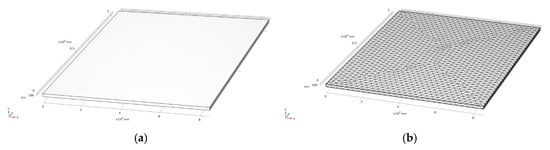
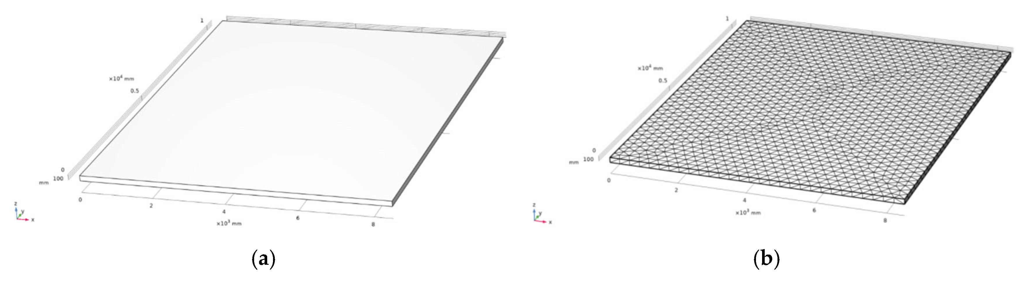
In this study, a three-dimensional plate–shell structural model was constructed using the COMSOL multi-physics 6.2 software, with precise dimensions of 10,400 mm in length, 8500 mm in width, and 150 mm in height. Considering the multi-physics coupling characteristics and geometric complexity of the concrete slab, an adaptive size control technique was employed for mesh discretization. The global maximum element size was set to 1040 mm, with local refinement to 187 mm, a growth rate of 1.5, a curvature factor of 0.6, and a narrow region resolution of 0.5. As illustrated in Figure 5, the concrete parameters required for computational analysis are provided in Table 3.
Figure 5.
Modeling and meshing. (a) Geometric model; (b) model mesh division.
Table 3.
Parameters required for the calculation of concrete coupled thermal and moisture deformation.
2.4.2. Moisture Diffusion Model
The modified moisture diffusion equation considering the Knudsen diffusion effect can be expressed as Equation (7) [55]:
where M is the moisture content (kg/m3), representing the mass of water within a unit volume of concrete; Dmk is the modified moisture diffusion coefficient (m2/s), where Dmk = Dm × kt, Dm is the unmodified moisture diffusion coefficient reflecting pure Fickian diffusion, and kt is the Knudsen diffusion influence coefficient, used to correct the diffusion limitation caused by the pore structure in porous media; Qm is the moisture source or sink (kg/(m3·s)), including moisture changes caused by non-diffusion processes such as hydration reaction, water production, and environmental moisture exchange. This equation is suitable for describing the dynamic evolution of the internal humidity gradient affected by the pore structure and hydration reaction during the early curing process of concrete and has a higher accuracy for the humidity field simulation with low water–cement ratio and high-density concrete. The key correction term, the Knudsen diffusion influence coefficient kt, is expressed as Equation (8):
where λ is the mean free path of water vapor molecules (approximately 0.1 μm at room temperature), and d is the average diameter of concrete pores (typically 10 nm~l μm).
When d > λ (large pores) and kt → 1, diffusion is dominated by the Fick mechanism.
When d ≤ λ (micro-nano pores) and kt < 1, the Knudsen effect is significant, and the diffusion rate decreases.
2.4.3. Heat Transfer Model
The heat transfer in cement-based materials is centered on Fourier’s law [55,56]. The thermal conductivity has comprehensively considered the influence of complex factors such as internal convection, and its porous medium thermal model can be simplified as Equation (9):
where T is the temperature (°C); λ is the apparent thermal conductivity (W/(m·K)), which integrates the equivalent heat transfer effects of conduction, micro-convection, and radiation; Q is the heat source term (W/m3), mainly characterizing the cement hydration heat release rate; ρ is the apparent density of the material (kg/m3); and cp is the specific heat capacity (J/(kg·K)). Among them, the thermal conductivity of concrete needs to consider the micro-convection effect of pore water. The apparent thermal conductivity can be expressed as a formula of temperature, as shown in Equation (10):
where Tref = 20 °C. When the temperature rises, the viscosity of pore water decreases, enhancing micro-convection heat transfer, resulting in an increase in λ. The exponential decay expression of the hydration heat source term Q is shown in Equation (11):
where Q∞ = 350 kJ/kg is the final hydration heat release; α(t) is the degree of hydration (0 ≤ a ≤ 1).
2.4.4. Mechanical Equilibrium Equation
Assuming that the concrete is subjected to uniform multi-source stress, and incorporating humidity, pore pressure and temperature deformation, the constitutive relationship is simplified to the total strain equals the superposition of each source strain, as shown in Equation (12):
where εe is the elastic strain, caused by external loads, which obeys Hooke’s law, where the elastic modulus E dynamically changes with temperature (T) and relative humidity (RH); εt is the thermal strain, calculated by the linear thermal expansion coefficient; and εsh is the drying shrinkage strain, driven by the humidity gradient, and adopts the moisture expansion coefficient model, as shown in Equation (13):
Assuming that the volume expansion caused by the model temperature change is isotropic, and has linear characteristics within a small temperature range (∆T < 50 °C), the thermal expansion coefficient αT can be taken as 10 × 10−6/°C. The moisture expansion coefficient βH (/%RH) is defined as the linear strain caused by every 1% change in humidity.
The stress estimates presented herein assume moderate internal restraint, as sensors were placed away from highly restrained edges. In practice, boundary restraints from beams and formwork can significantly amplify local stresses [57,58].
3. Results and Discussion
3.1. Mechanical Properties
3.1.1. Compressive Strength
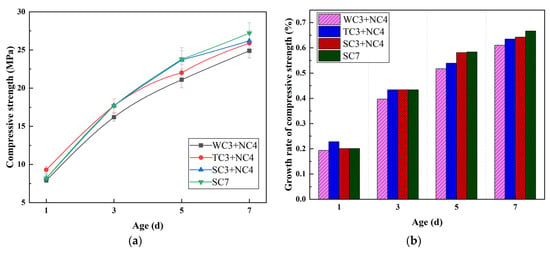
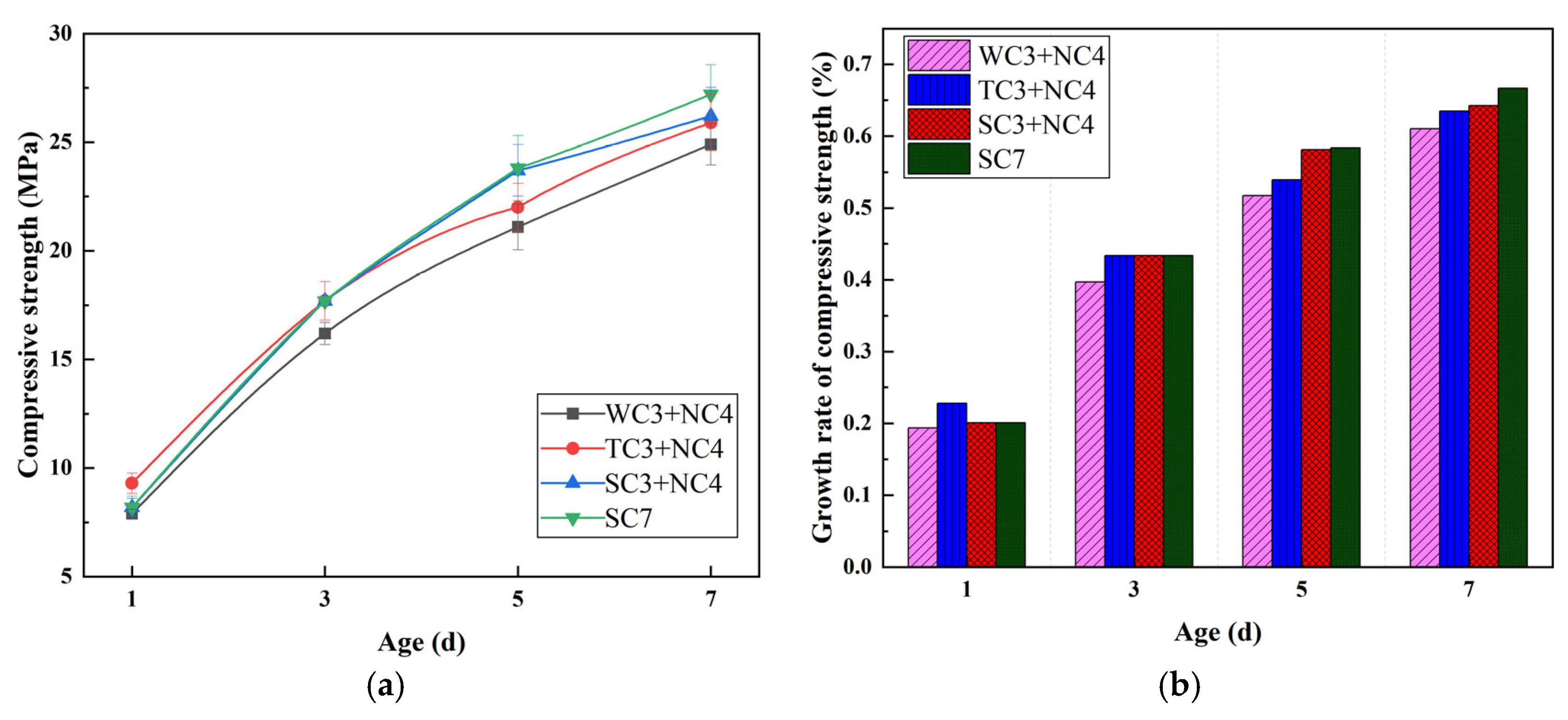
The compressive strength results of concrete under different curing methods are shown in Figure 6. As depicted, different curing regimes significantly influence the early compressive strength development of C30 concrete. The SC7 group exhibited a 7-day compressive strength of 27.2 MPa, which was higher than other curing methods. This is attributed to the constant temperature and humidity environment that continually promotes cement hydration reactions, forming more C-S-H gels and resulting in a denser microstructure [59,60]. The SC3 + NC4 group achieved the same strength as the SC7 group in the early stage (3 days). However, in the later stage, due to the fluctuation of temperature and humidity during the natural curing phase, water evaporation occurred, slowing the hydration rate, thereby reducing the 7-day strength to 26.2 MPa. The TC3 + NC4 group exhibited higher early strength, but the growth rate slowed in the later stage due to interrupted curing, reaching a 7-day strength of 25.9 MPa. In contrast, the WC3 + NC4 group demonstrated the slowest strength development, achieving only 24.9 MPa by 7 days. This may be because the film covering reduced water loss but hindered CO2 diffusion, thereby delaying the carbonation process [61,62]. Overall, full-period standard curing is the optimal choice for maximizing the compressive strength of concrete, while the TC3 + NC4 scheme can serve as a feasible alternative to balance efficiency and performance under restricted engineering conditions.
Figure 6.
Concrete compressive strength under different curing methods. (a) Compressive strength; (b) growth rate of compressive strength.
3.1.2. Splitting Tensile Strength
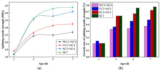
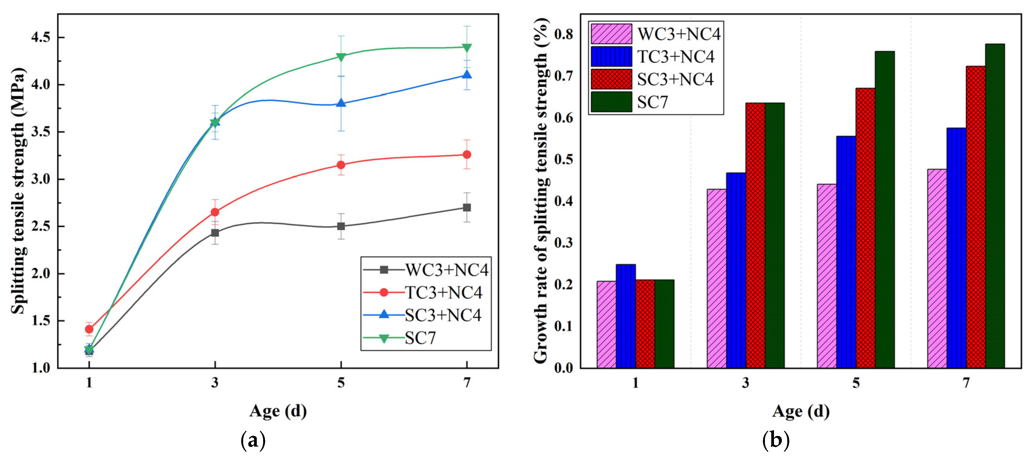
As shown in Figure 7, the splitting tensile strength of concrete is more sensitive to the curing regime than its compressive strength. The SC7 group achieved a 7-day splitting tensile strength of 4.4 MPa. The SC3 + NC4 group initially exhibited similar strength to the SC7 group, but after 3 days, due to temperature and humidity fluctuations during the natural curing phase, moisture evaporation occurred, reducing the hydration rate. This resulted in a decrease in the 7-day strength to a value of 4.1 MPa, a reduction of 6.8%. The TC3 + NC4 group showed a higher early strength (1.41 MPa) at 1 day, but the strength growth slowed down in the later stage due to interrupted curing, with a 7-day strength of 3.26 MPa, which was 25.9% lower than the SC7 group. In contrast, the concrete that only underwent 3 days of wet curing followed by 4 days of natural curing (WC3 + NC4) exhibited the slowest strength development, with a 7-day strength of only 2.7 MPa. This may be because the film covering reduced the water loss but did not control temperature fluctuations, leading to the concentration of internal thermal stress and the formation of penetrating microcracks [63].
Figure 7.
Concrete splitting tensile strength under different curing methods. (a) Splitting tensile strength; (b) growth rate of splitting tensile strength.
3.1.3. Elastic Modulus
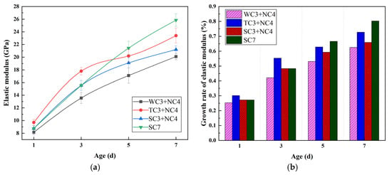
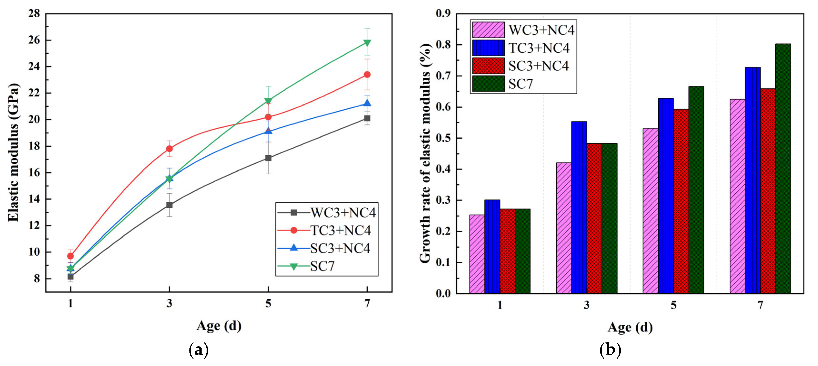
The results in Figure 8 indicate that the elastic modulus of each group of specimens showed a continuous increasing trend, but there were significant differences under different curing regimes. The SC7 group exhibited the best performance, with a 7-day elastic modulus of 25.85 GPa, reaching 80.0% of the 28-day value. The TC3 + NC4 group developed rapidly in the early stage, reaching 23.4 GPa at 7 days, which was 72.4% of the 28-day value, only 7.6% lower than the SC7 group. However, the growth rate of SC3 + NC4 and WC3 + NC4 decreased sharply after 3 days due to exposure curing, reaching only 65.6% and 62.2% at 7 days, respectively. The high elastic modulus of SC7 is due to the continuous hydration reaction in a constant temperature and humidity environment, which promotes the continuous formation of CSH gel and the densification of the microstructure [64]. The early advantage of TC3 + NC4 is due to the thermal acceleration effect, but the later natural curing limited the final performance development. SC3 + NC4 and WC3 + NC4 experienced hydration stagnation and increased porosity due to moisture loss [65].
Figure 8.
Concrete elastic modulus under different curing methods. (a) Elastic modulus; (b) growth rate of elastic modulus.
3.2. Temperature–Humidity and Stress
3.2.1. Temperature
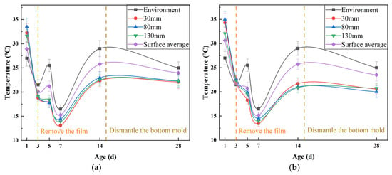
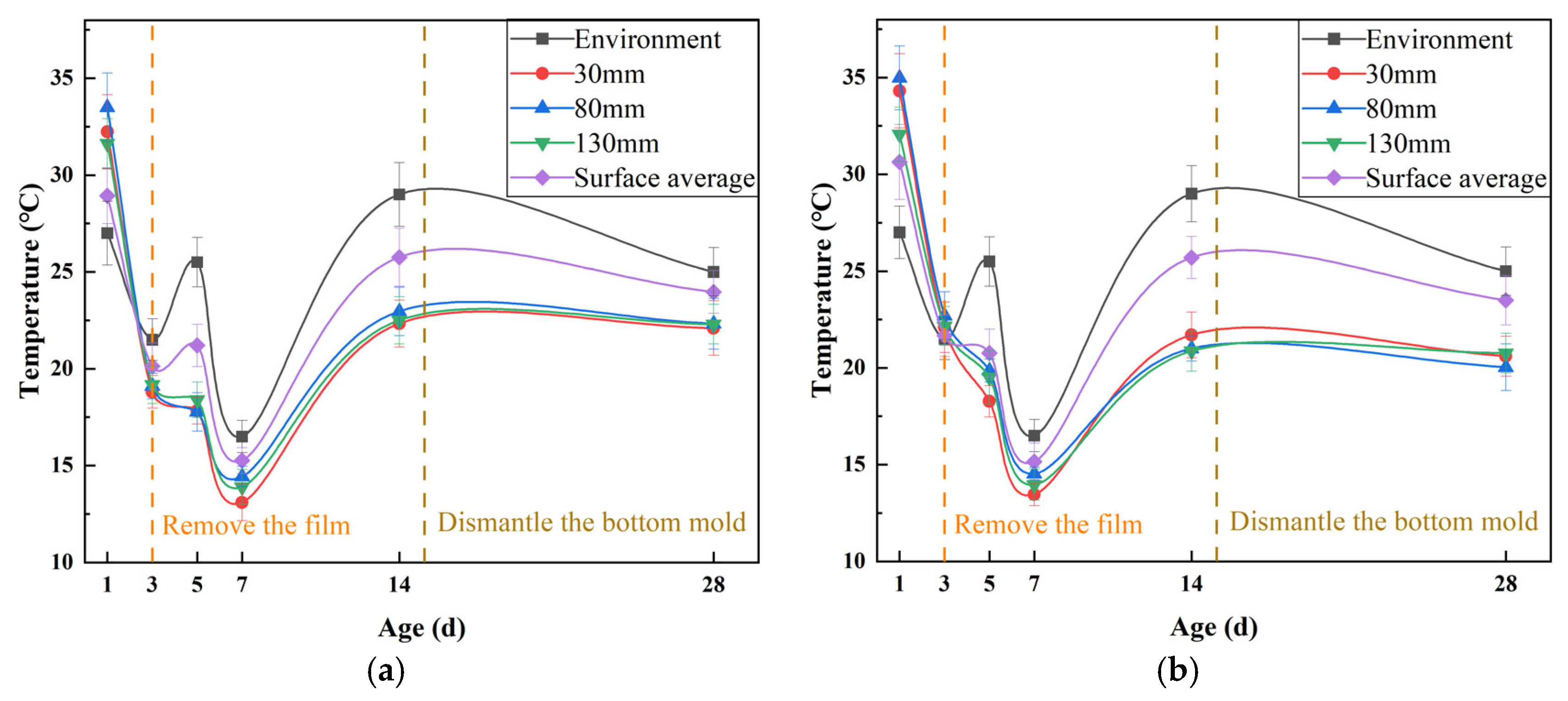
As shown in Figure 9, under WC conditions, the concrete exhibits a vigorous hydration reaction on day 1, with temperatures at depths of 30 mm, 80 mm, and 130 mm reaching 32.23 °C, 33.5 °C, and 31.63 °C, respectively, significantly higher than the ambient temperature. However, after removing the curing film on day 3, a rapid temperature drop occurs, indicating that single moisturizing measures have limitations in temperature control. Regarding depth differences, the temperature variation across different depths is small on day 1. However, after 3 days, the temperature decrease rate at the 30 mm depth is higher than that at the 130 mm depth, reflecting the gradient characteristic of heat transfer from the inside to the outside. In terms of temperature exchange equilibrium, after dismantling the bottom mold on day 15, the concrete exchanges temperature more fully with the environment, and temperature fluctuations tend to align with the environment.
Figure 9.
Temperature of large-area concrete slab. (a) WC; (b) TC.
TC demonstrates significant temperature control advantages. Its aluminum foil–insulation cotton composite system increases the internal temperature by 1.47–2.91 °C compared to WC on day 1, with the peak temperature at the 30 mm depth reaching 34.31 °C. The synergistic effect of heat reflection and insulation reduces the cooling rate by 15–20%, and the internal temperature difference on day 3 is reduced by 38% compared to WC. Mechanism research shows that TC regulates the temperature field through the following triple action: the aluminum foil layer effectively blocks radiative heat dissipation [66,67], the insulation cotton inhibits convective heat transfer [66], and the sealed structure maintains a relative humidity >90% to continuously promote hydration heat release [68]. This multi-physics coupling effect stabilizes the internal temperature at 22.32 ± 0.54 °C between 3 and 7 days, and the temperature gradient is reduced to 1.1 °C/10 cm, which is 42% of that of the WC system. In addition to average temperatures, the peak internal temperature gradient under WC reached 2.8 °C/10 cm on day 3 (between 30 mm and 80 mm), whereas TC limited this to 1.1 °C/10 cm, confirming its effectiveness in suppressing critical thermal differentials.
From an engineering timeliness perspective, the temperature behavior of TC after 14 days is similar to that of WC. However, the temperature and humidity environment established in the critical early stage increases the concrete’s crack resistance coefficient by 1.8 times. This phase-specific regulation characteristic indicates that TC technology is suitable for large-area concrete structures and can shorten the critical curing time by 40% within a 21-day standard curing cycle.
3.2.2. Humidity
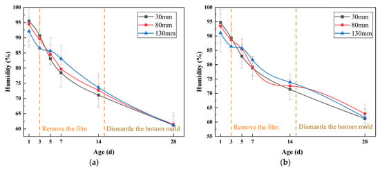
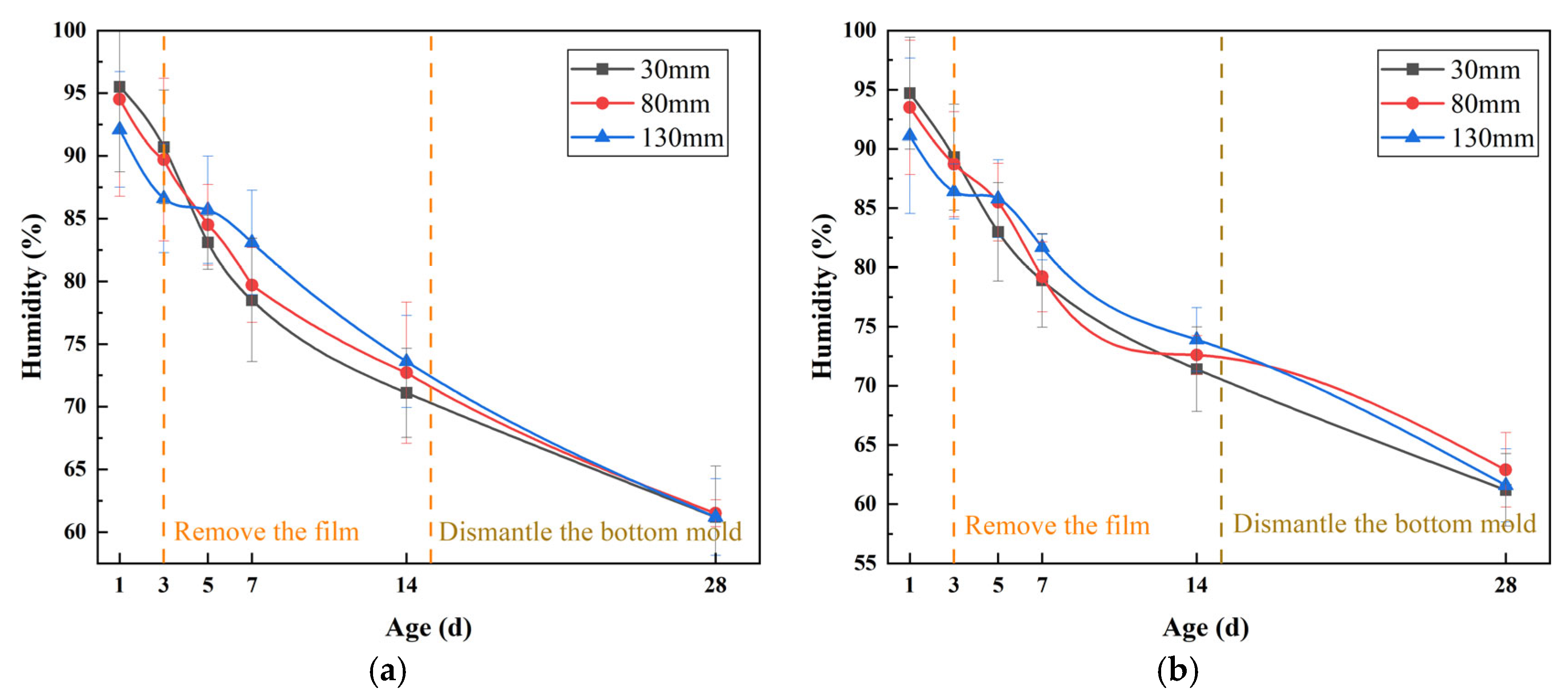
As shown in Figure 10, under WC conditions, the internal humidity of the concrete decreases with age. The average humidity drops from 94% to 61.3% between 1 and 28 days, a reduction of 34.8%. This indicates that the hydration reaction is the main reason for the consumption of free water [69], while environmental humidity fluctuations have a limited impact on internal humidity. Humidity gradient analysis shows that the humidity decrease rate at a depth of 30 mm is 6.8% faster than at a depth of 130 mm due to stronger evaporation. However, by day 28, the humidity at each depth tends to be consistent, indicating that long-term moisture diffusion makes the humidity distribution uniform. After removing the film, the moisture exchange accelerates, further exacerbating the humidity decrease, indicating that the moisturizing effect of WC is only effective in the short term.
Figure 10.
Humidity of large-area concrete slab. (a) WC; (b) TC.
TC demonstrates a better humidity control ability. The humidity reduction from day 1 to day 28 is slightly lower than that of WC, and the humidity difference at each depth decreases from the initial 3.6% to 1.7%, indicating that its composite structure effectively delays moisture migration [70]. Mechanism research shows that the insulation cotton reduces the evaporation rate by inhibiting heat loss [71], while the aluminum foil blocks external radiation interference [65], maintaining the internal temperature and humidity balance. Although the long-term humidity is close to that of WC, TC has better humidity stability in the critical curing period, providing a continuous and suitable environment for the hydration reaction.
Both curing methods are dominated by the hydration reaction, but TC mitigates early-age humidity gradients by concurrently regulating temperature and moisture transport, which is especially suitable for engineering environments with large humidity fluctuations.
3.2.3. Stress
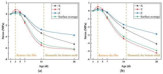
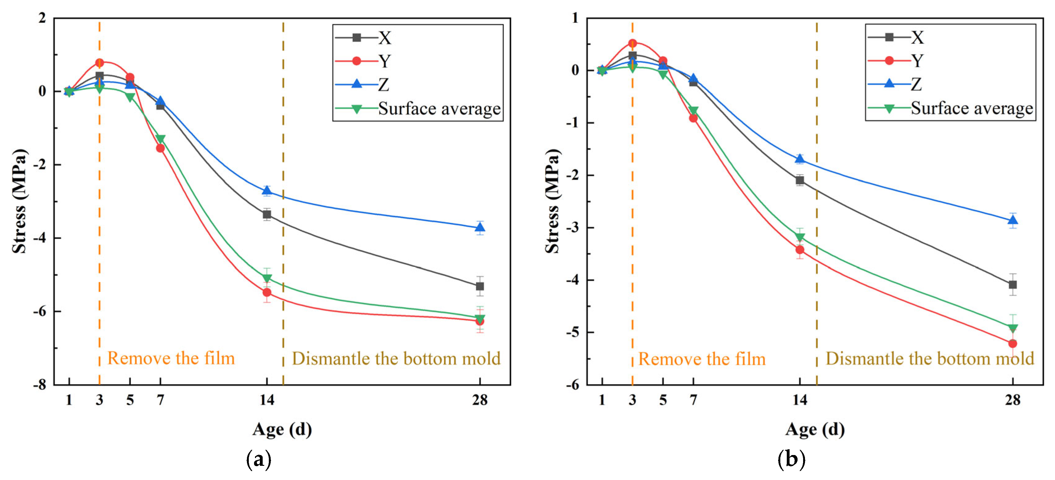
As shown in Figure 11, the stress of concrete under WC conditions shows typical two-stage characteristics: early hydration heat accumulation leads to the development of compressive stress, while the later temperature drop and shrinkage dominate the stress reversal, and the tensile stress increases significantly after 28 days. This phenomenon stems from the initial suppression of moisture evaporation by the film covering, which delays but does not block heat loss. After removing the curing film on day 3, environmental interaction accelerates the accumulation of shrinkage stress. It is worth noting that the stress in the Y direction is always 23.6% higher than that in the X direction, indicating that the structural constraints have a certain tonal control effect on the stress distribution.
Figure 11.
Stress of large-area concrete slab. (a) WC; (b) TC.
TC regime shows a more complex three-stage characteristic of “early micro-compression, mid-term reversal, and long-term continuous shrinkage.” The early insulation–aluminum foil composite curing regime reduces the peak compressive stress by 37.5%. After removing the curing film at the mid-term stage, the environmental temperature dropped sharply. Elastic strain dominated the development of tensile stress, but residual creep capacity and thermal hysteresis effects still delayed stress reversal for 48 h. Finally, the long-term tensile stress exhibited an 18.4% reduction in development rate compared to WC. Mechanistic analysis shows that the insulation cotton prolongs the hydration heat release cycle, reducing the temperature gradient to 1.2 °C/10 cm. The aluminum foil reflective layer reduces surface radiation heat dissipation [65], inhibiting local shrinkage differences. Consequently, a 48 h delay in stress reversal occurs during the intermediate stage. However, environmental exposure after the removal of the curing film still makes the final tensile stress approach the WC level, indicating that short-term insulation cannot completely offset the long-term shrinkage effect.
From the perspective of engineering applicability, the stress difference between WC and TC on day 28 is less than 15%, but TC reduces the stress mutation range by 42% over days 3–7, which is crucial for early crack resistance. Therefore, for structural parts with strong constraints, it is recommended to use TC to delay early stress accumulation.
3.3. Numerical Simulation Analysis
3.3.1. Simulated Slab Temperature Analysis
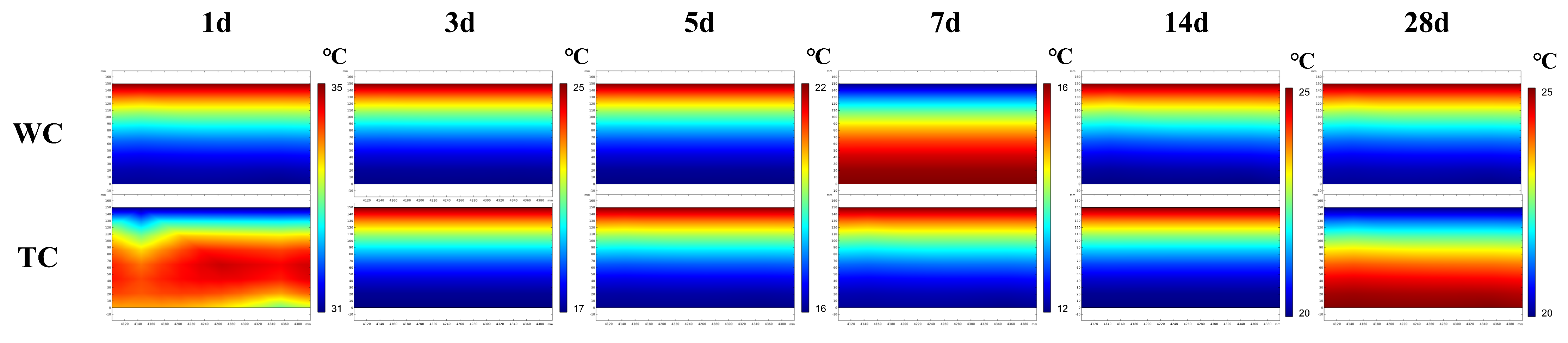
The simulated temperatures of WC and TC slabs at various ages are shown in Figure 12.
Figure 12.
Simulated temperature of large-area concrete slab.
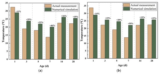
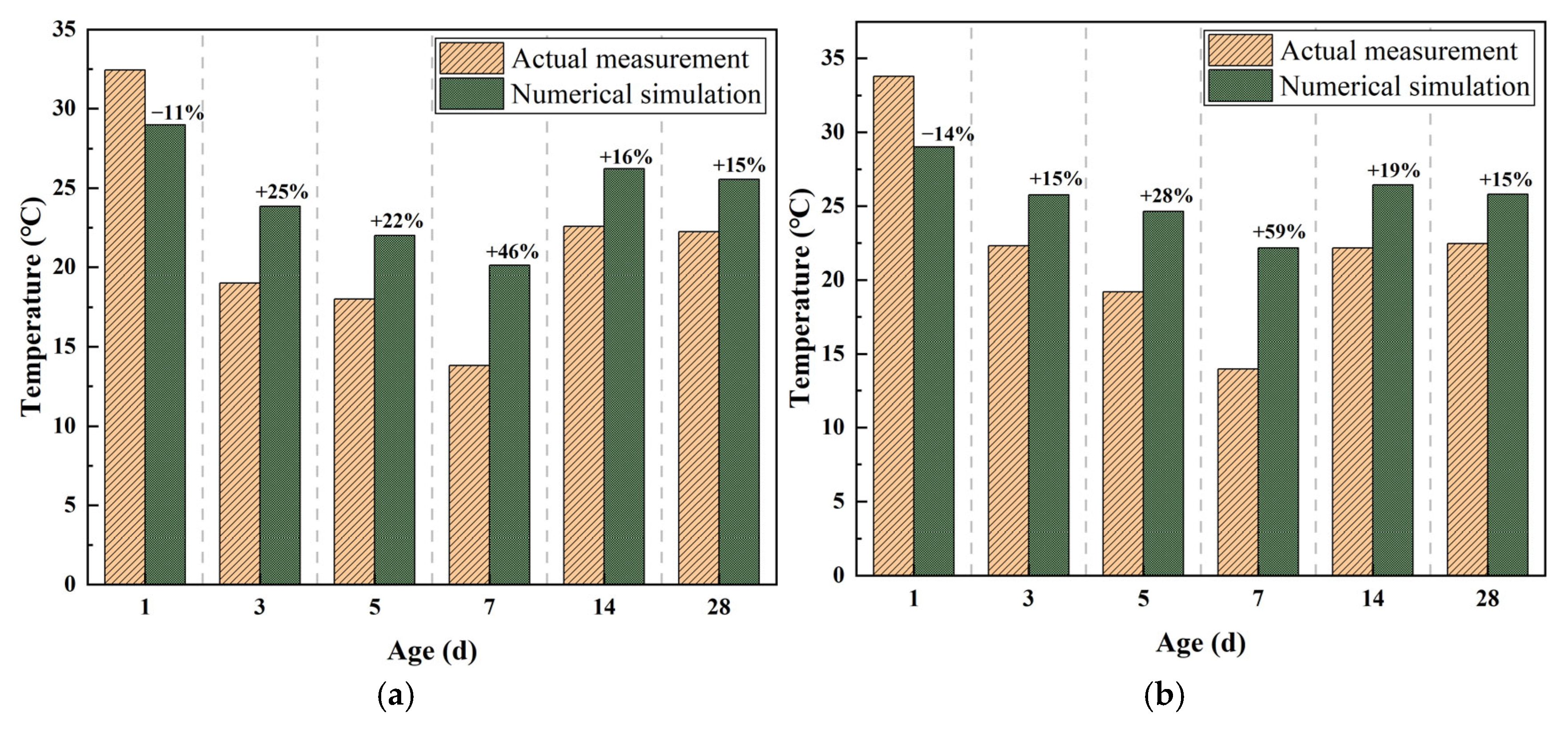
Figure 13 compares simulated and measured temperatures. In the early stage (days 1–3), simulations underestimate temperatures by 3.48 °C (WC) and 4.78 °C (TC), mainly due to inadequate modeling of insulation effects—particularly the high reflectivity of aluminum foil and thermal resistance of insulation cotton—as well as the insufficient representation of heat accumulation during covered curing in the hydration heat release model. In the mid-term (days 5–7), simulated temperatures exceed measurements, reflecting inaccurate post-removal boundary conditions: the model underestimates convective heat loss by 18.7% and neglects the cooling effect associated with self-desiccation shrinkage. By the long term (days 14–28), the simulation accuracy markedly improves, indicating that the thermodynamic model performs well under environment-dominated conditions where external heat exchange governs temperature evolution.
Figure 13.
Comparison of simulated temperature and actual measured temperature. (a) WC; (b) TC.
From a model optimization perspective, the early temperature discrepancy arises from inadequate multi-physical field coupling: the model omits the 42% reduction in surface heat flux due to aluminum foil’s reflectivity and uses standard hydration parameters without accounting for the heat storage effect of covered curing. The mid-term deviation reflects weak mass–heat transfer coupling, as the actual convection coefficient after curing-layer removal is 35–40% higher than simulated.
3.3.2. Simulated Humidity Analysis
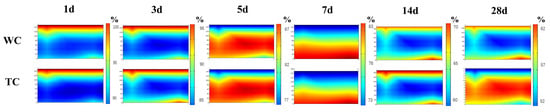
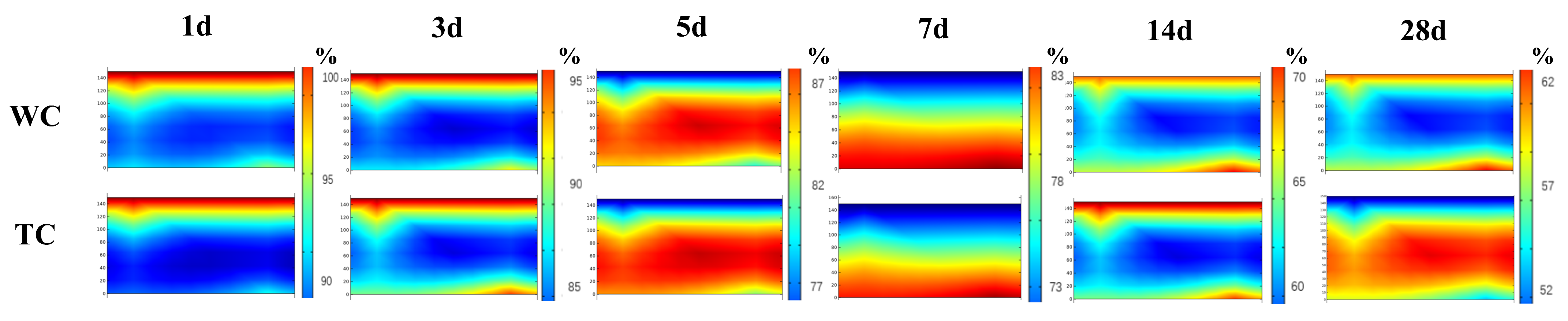
Figure 14 illustrates the simulated humidity levels in WC and TC slabs across various ages.
Figure 14.
Simulated humidity of large-area concrete slab.
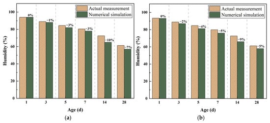
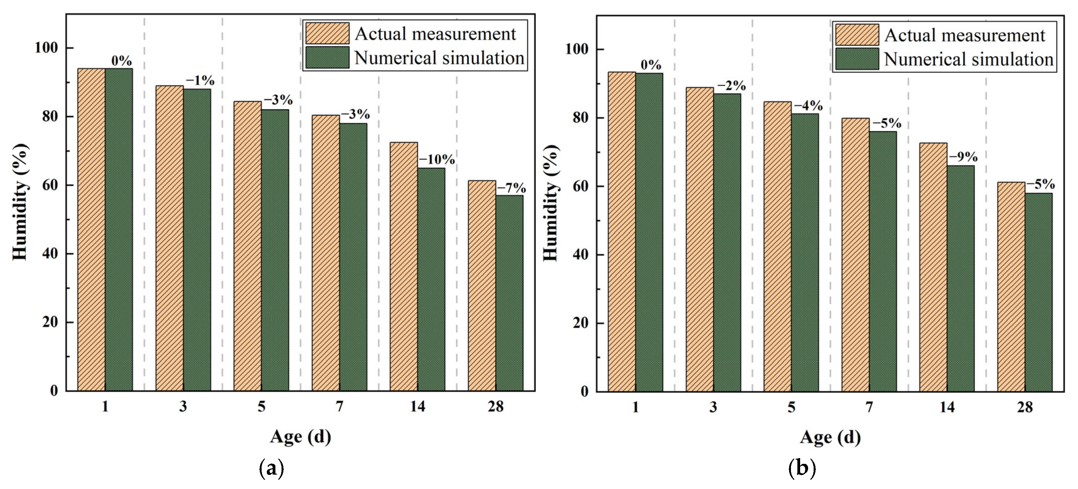
Figure 15 shows that the simulated slab humidity trends closely match measured data. During early curing (1–3 days), simulation errors are below 1%, thanks to accurate material parameter calibration and the effective modeling of the hydration–evaporation balance under intact cover layers. Under TC, slightly higher errors (0.4–1.8%) suggest that the model needs refinement in representing the multi-layer mass transfer barrier of composite insulation. In the mid-term (days 5–7), errors rise to 2.4–3.9%, mainly due to the following: (1) a ~35% underestimation of the boundary convection coefficient after cover removal, reducing surface moisture exchange accuracy; (2) incomplete coupling between self-desiccation and external drying; and (3) insufficient incorporation of time-varying ambient humidity. By the long term (14–28 days), errors widen to 5.2–7.0%, primarily because the model does not account for rapid moisture pathways created by microcracks or accurately simulate the 3D humidity field reconstruction following formwork removal—highlighting discrepancies between idealized assumptions and real material behavior.
Figure 15.
Comparison of simulated humidity and actual measured temperature. (a) WC; (b) TC.
The numerical simulation reliably captures early-age humidity but struggles with mid-term curing-layer removal and long-term microcrack effects. Key errors stem from oversimplified boundary dynamics, insufficient multi-field coupling, and the inadequate representation of material damage evolution.
3.3.3. Simulated Slab Stress Analysis
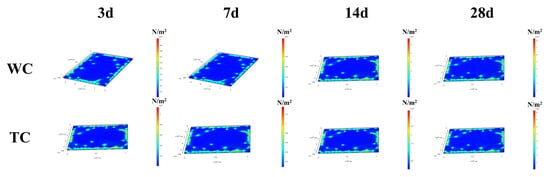
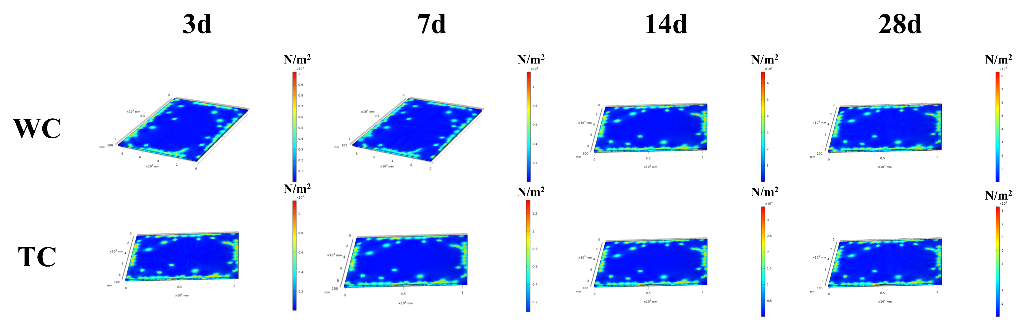
Figure 16 shows the simulated stress in WC and TC slabs at various ages.
Figure 16.
Simulated stress of large-area concrete slab.
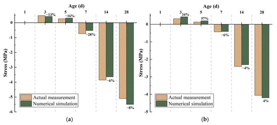
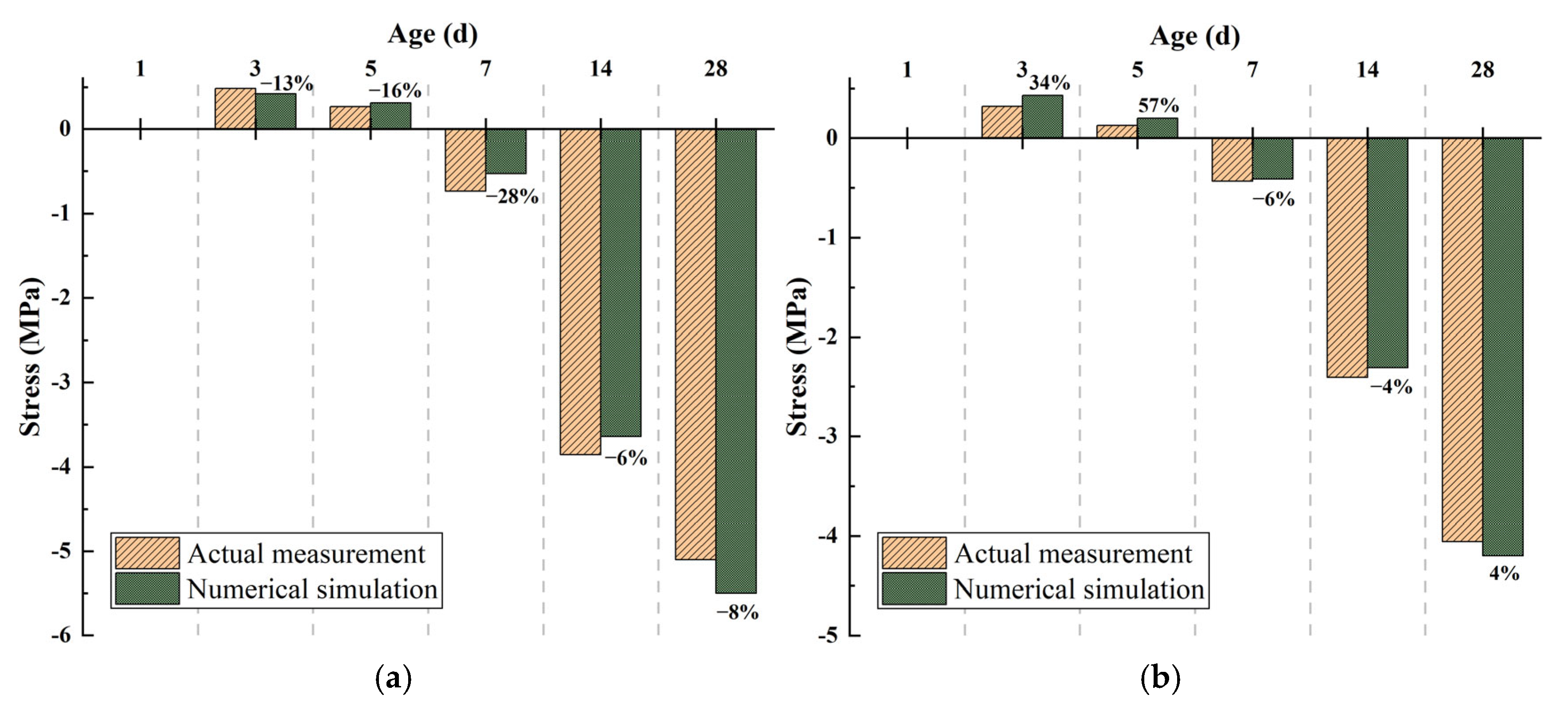
Figure 17 shows that simulated stress trends generally align with measured data, though discrepancies vary by curing regime and age. During early curing (days 1–3), WC simulations slightly underestimate compressive stress on day 3 but overestimate it on day 5 (error: 0.043–0.062 MPa). Under TC, simulated compressive stress is notably higher on day 3 (error: 0.109 MPa), decreasing to 0.073 MPa by day 5. On day 7 (mid-term), WC-simulated tensile stress is 28.2% lower than measured, while TC shows good agreement (5.5% error). In the long term (days 14–28), WC simulation underestimates stress on day 14 but overestimates it markedly on day 28 (7.8% error). TC exhibits smaller long-term errors and better overall consistency, indicating superior model performance under thermal–moisture coupled curing conditions.
Figure 17.
Comparison of simulated stress and actual measured stress. (a) WC; (b) TC.
Errors primarily arise from insufficient multi-physical field coupling: early underestimation of aluminum foil’s thermal reflectivity and incomplete humidity–shrinkage coupling; mid-term oversimplification of transient heat–moisture exchange after curing removal, neglecting dynamic boundary effects and the synergy between self-desiccation and thermal shrinkage; and long-term omission of creep relaxation and inaccurate ambient humidity modeling. However, the consistent results obtained through thermal control curing indicate that this model provides a relatively reliable characterization of the thermal and humidity inertia properties of composite insulation materials.
4. Conclusions
This study systematically revealed the effects of different curing regimes on the early-age mechanical properties of C30 concrete and the hygrothermal–mechanical behavior of large-scale slab specimens through a combination of experimental tests and numerical simulations. The main conclusions are as follows:
- (1)
- While standard curing maximizes mechanical properties by sustaining ideal saturation, the TC3 + NC4 regime demonstrates that strategic modulation of thermal–moisture exchange can effectively mitigate long-term strength loss under field constraints, revealing that performance resilience can be engineered through temporal control of the curing environment.
- (2)
- TC’s dual-layer insulation decouples internal exotherm from surface cooling, maintaining a quasi-steady thermal field during critical early hours. In contrast, abrupt boundary changes in WC trigger transient thermal imbalances, proving that boundary transience, not just magnitude, drives stress concentration.
- (3)
- TC exhibits significant regulatory effects on stress development. TC significantly enhances crack resistance by delaying moisture and heat loss, thereby postponing shrinkage and thermal contraction until the concrete matrix has developed sufficient stiffness and creep compliance—effectively mitigating both average and localized peak stress concentrations.
- (4)
- Compared with conventional numerical approaches that typically assume homogeneous material properties, simplified boundary conditions, or decoupled thermal–mechanical fields. The developed multi-physics coupling model reliably reproduced the coupled evolution of temperature, humidity, and stress fields, achieving long-term (after day 14) prediction accuracy with a maximum error not exceeding 8%. However, under thermal curing conditions (days 0–7), significant deviations exist in temperature predictions during the early aging stage. This is attributed to insufficient characterization of radiative heat transfer at the aluminum foil–air interface. Therefore, future work will incorporate a microcrack damage evolution submodel into this framework.
Future work will incorporate spectrally resolved radiative boundary conditions and enhance early-stage stress prediction accuracy by calibrating thermal properties of the insulation layer in situ. A fully coupled thermal–humidity–stress–damage (THMD) four-field framework will be developed to correlate predicted tensile stress fields with microcrack density, dynamically updating material permeability and diffusion parameters.
Author Contributions
Conceptualization and writing—original draft preparation, X.H.; formal analysis and writing—review and editing, R.Y.; methodology and software, X.C.; writing—review and editing, F.M.; visualization, X.Y.; and formal analysis, M.Z. All authors have read and agreed to the published version of the manuscript.
Funding
This research received no external funding.
Data Availability Statement
The data presented in this study are available upon request from the corresponding author.
Conflicts of Interest
The authors declare no conflicts of interest.
References
- Lin, W.; Wu, M.; Zhang, Y.; Zeng, R.; Zheng, X.; Shao, L.; Zhao, L.; Li, S.; Tang, Y. Regional differences of urbanization in China and its driving factors. Sci. China Earth Sci. 2018, 61, 778–791. [Google Scholar] [CrossRef] [Scilit]
- Yang, S.; Shi, L. Prediction of long-term energy consumption trends under the New National Urbanization Plan in China. J. Clean. Prod. 2017, 166, 1144–1153. [Google Scholar] [CrossRef] [Scilit]
- Zhang, S.; Li, Z.; Ning, X.; Li, L. Gauging the impacts of urbanization on CO2 emissions from the construction industry: Evidence from China. J. Environ. Manag. 2021, 288, 112440. [Google Scholar] [CrossRef] [Scilit]
- Zhang, L. Analysis on Design and Application of Concrete Structure in Modern Urban High-Rise Buildings. Adv. High. Educ. 2019, 3, 140. [Google Scholar] [CrossRef] [Scilit]
- Qu, J.; Wang, Z.; Du, P. Comparative Study on the Development Trends of High-rise Buildings Above 200 Meters in China, the USA and the UAE. Int. J. High-Rise Build. 2021, 10, 63–71. [Google Scholar]
- Zhang, L.; Dong, M. Assessment of CO2 emissions in large-span, heavy-load buildings: A comparative study of multi-ribbed concrete composite slabs and traditional cast-in-place concrete slabs. J. Clean. Prod. 2025, 521, 146187. [Google Scholar] [CrossRef] [Scilit]
- Elansary, A.; Mabrouk, A.; Zawam, M.; El-Attar, A. Staged-Construction Analysis of High-Rise Buildings with Post-tension Slabs. Arab. J. Sci. Eng. 2022, 47, 5281–5302. [Google Scholar] [CrossRef] [Scilit]
- Schackow, A.; Effting, C.; Gomes, I.R.; Patruni, I.Z.; Vicenzi, F.; Kramel, C. Temperature variation in concrete samples due to cement hydration. Appl. Therm. Eng. 2016, 103, 1362–1369. [Google Scholar] [CrossRef] [Scilit]
- Aniskin, N.; Nguyen, T.C. Influence factors on the temperature field in a mass concrete. E3S Web Conf. 2019, 97, 05021. [Google Scholar] [CrossRef] [Scilit]
- Ali, A.F.; Al-Damluji, O.A.-F.; Al-Zuhairi, A.A.H.A. Effect of Transverse Base Width Restraint on the Cracking Behavior of Massive Concrete. J. Eng. 2023, 18, 1201–1218. [Google Scholar] [CrossRef] [Scilit]
- Ding, K.; Shi, J.; Chen, S. Review on stress evolution and crack propagation mechanism of double-crack specimens. Mech. Adv. Mater. Struct. 2023, 31, 7968–7975. [Google Scholar] [CrossRef] [Scilit]
- Kuriakose, B.; Rao, B.N.; Dodagoudar, G.R. Early-age Temperature Distribution in a Massive Concrete Foundation. Procedia Technol. 2016, 25, 107–114. [Google Scholar] [CrossRef] [Scilit]
- Otieno, M.B.; Alexander, M.G.; Beushausen, H.D. Corrosion in cracked and uncracked concrete—Influence of crack width, concrete quality and crack re-opening. Mag. Concr. Res. 2010, 62, 393–404. [Google Scholar] [CrossRef] [Scilit]
- Wang, X.; Ba, M.; Yi, B.; Liu, J. Experimental and numerical investigation on the effect of cracks on chloride diffusion and steel corrosion in concrete. J. Build. Eng. 2024, 86, 108521. [Google Scholar] [CrossRef] [Scilit]
- Cheng, Y.; Zhang, Y.; Tan, G.; Jiao, Y. Effect of Crack on Durability of RC Material under the Chloride Aggressive Environment. Sustainability 2018, 10, 430. [Google Scholar] [CrossRef] [Scilit]
- Kosonen, R.; Jokisalo, J.; Ranta-Aho, I.; Koikkalainen, E.-P. Methods to Reduce Stack Effect and Improve Energy Efficiency in a Nordic High Rise Residential Building. Procedia Eng. 2017, 205, 2311–2317. [Google Scholar] [CrossRef] [Scilit]
- Banionis, K.; Šadauskienė, J.; Paukštys, V.; Šeduikytė, L.; Ramanauskas, J. Diagnostics and Problems Analysis of Buildings Air Tightness. J. Sustain. Archit. Civ. Eng. 2013, 3, 52–58. [Google Scholar] [CrossRef] [Scilit]
- Šadauskienė, J.; Paukštys, V.; Šeduikytė, L.; Banionis, K. Impact of Air Tightness on the Evaluation of Building Energy Performance in Lithuania. Energies 2014, 7, 4972–4987. [Google Scholar] [CrossRef] [Scilit]
- Shooshtarian, S.; Gurmu, A.T.; Sadick, A.M. Application of natural language processing in residential building defects analysis: Australian stakeholders’ perceptions, causes and types. Eng. Appl. Artif. Intell. 2023, 126, 107178. [Google Scholar] [CrossRef] [Scilit]
- Schindler, A.; Byard, B.; Tankasala, A. Mitigation of early-age cracking in concrete structures. MATEC Web Conf. 2019, 284, 07005. [Google Scholar] [CrossRef] [Scilit]
- Mapa, D.G.; Markandeya, A.; Sedaghat, A.; Riding, K.A.; Zayed, A. Effect of Different Cracking Mitigation Measures on High Early–Strength Concrete Performance. J. Mater. Civ. Eng. 2021, 33, 04021205. [Google Scholar] [CrossRef] [Scilit]
- Khan, M.; Ali, M. Use of glass and nylon fibers in concrete for controlling early age micro cracking in bridge decks. Constr. Build. Mater. 2016, 125, 800–808. [Google Scholar] [CrossRef] [Scilit]
- Wang, C.; Chen, Y.; Zhou, M.; Chen, F. Control of Early-Age Cracking in Super-Long Mass Concrete Structures. Sustainability 2022, 14, 3809. [Google Scholar] [CrossRef] [Scilit]
- Kumar, C.; Sinha, A.K. Automated Crack Detection and a Web Tool Using Image Processing Techniques in Concrete Structures. Russ. J. Nondestruct. Test. 2023, 59, 1119–1135. [Google Scholar] [CrossRef] [Scilit]
- Zhu, J. A Critical Review of Crack Detection Based on Image Processing. J. Comput. Nat. Sci. 2023, 3, 204–215. [Google Scholar] [CrossRef] [Scilit]
- Nguyen, C.; Kawamura, K.; Nakamura, H.; Tarighat, A. Research on Automatic Crack Detection for Concrete Infrastructures Using Image Processing and Deep Learning. IOP Conf. Ser. Mater. Sci. Eng. 2021, 829, 012027. [Google Scholar]
- Rajadurai, R.S.; Kang, S.T. Automated Vision-Based Crack Detection on Concrete Surfaces Using Deep Learning. Appl. Sci. 2021, 11, 5229. [Google Scholar] [CrossRef] [Scilit]
- Wang, X.F.; Zheng, J.L. Influence of Compounded Mineral Admixtures on Shrinkage and Early-Age Cracking Behaviors of Concrete. Adv. Mater. Res. 2012, 450–451, 738–742. [Google Scholar] [CrossRef] [Scilit]
- Ibrahim, M.A.; Dulawat, S.; Ahmad, E.; Ibrahim, I.A.; Ibrahim, U.S.; Ubayi, S.S.; Ishaq, I.Z. A Review on the Curing of Concrete using Different Methods. Int. J. Mech. Civ. Eng. 2024, 7, 15–25. [Google Scholar] [CrossRef] [Scilit]
- Xu, D.; Tang, J.; Hu, X.; Yu, C.; Han, F.; Sun, S.; Deng, W.; Liu, J. The influence of curing regimes on hydration, microstructure and compressive strength of ultra-high performance concrete: A review. J. Build. Eng. 2023, 76, 107401. [Google Scholar] [CrossRef] [Scilit]
- Raza, M.S.; Kumar, H.; Kumar, D.; Bheel, N. Effect of Various Curing Methods and Curing Days on Compressive Strength of Plain Cement Concrete. Quaid-E-Awam Univ. Res. J. Eng. Sci. Technol. 2020, 18, 29–32. [Google Scholar]
- Lura, P.; Breugel, K.V.; Maruyama, I. Effect of curing temperature and type of cement on early-age shrinkage of high-performance concrete. Cem. Concr. Res. 2001, 31, 1867–1872. [Google Scholar] [CrossRef] [Scilit]
- Zhu, P.; Zhou, X.G. Effect of Curing Temperature on the Properties of Concrete at Early Age. Appl. Mech. Mater. 2013, 351–352, 1687–1693. [Google Scholar] [CrossRef] [Scilit]
- Lin, L.; Wang, S.; Zhang, P.; Li, J.; Wang, S.; Zhong, J.; Zeng, L.; Qiu, X. Effect of curing regime on the strength development and microstructure evolution of high strength concrete. J. Build. Eng. 2023, 78, 107750. [Google Scholar] [CrossRef] [Scilit]
- Wang, Y.; Xue, S.; Li, X.; Geng, Y.; Rong, H.; Lu, X. Effect of curing temperatures on the early-age tensile creep behavior of high-performance concrete. Case Stud. Constr. Mater. 2025, 22, e04729. [Google Scholar] [CrossRef] [Scilit]
- Chen, D. Multi-physical field coupling simulation of hygro-thermal deformation of concrete. J. Southeast Univ. 2013, 43, 582–587. [Google Scholar]
- Chen, D.P.; Miao, C.W.; Liu, J.P.; Tong, M.S. Advances in multi-scale simulation of hygro-thermo- mechanical deformation behavior of structural concrete. Int. J. Civ. Eng. 2015, 13, 267–277. [Google Scholar]
- Ding, J.; Wang, X.; Lei, M.; Jiang, K.; Wu, Z. Cohesive element-based chemo-thermo-mechanical multi-field coupled cracking simulation of early-age concrete. Theor. Appl. Fract. Mech. 2024, 130, 104296. [Google Scholar] [CrossRef] [Scilit]
- Wang, T.; Li, D.; Zhou, J.; Zhang, J.; Cha, Y.J. Temperature Monitoring of Mass Concrete Structure Using Wireless Sensing System. Struct. Control. Health Monit. 2025, 2025, 7847074. [Google Scholar] [CrossRef] [Scilit]
- Zhang, Q.; Li, Y.; Huang, Y.; Li, Y.; Yang, Y.; Hu, Y. Utilizing 3D Printing and Distributed Optic Fiber to Achieve Temperature-Sensitive Concrete. Materials 2025, 18, 1897. [Google Scholar] [CrossRef] [Scilit]
- Lu, X.; Hicke, K.; Breithaupt, M.; Strangfeld, C. Distributed Humidity Sensing in Concrete Based on Polymer Optical Fiber. Polymers 2021, 13, 3755. [Google Scholar] [CrossRef] [Scilit] [PubMed]
- Pulecio-Díaz, J.; Sol-Sánchez, M.; Moreno-Navarro, F. Effects of Relative Humidity and Temperature on the Drying Shrinkage of Roller-Compacted Concrete Pavements. Infrastructures 2024, 9, 22. [Google Scholar] [CrossRef] [Scilit]
- Wang, S.; Yang, Z.; Mohanty, L.; Zhao, C.; Han, C.; Li, B.; Yang, Y. Distributed fiber optic sensing for internal strain monitoring in full life cycle of concrete slabs with BOFDA technology. Eng. Struct. 2024, 305, 117798. [Google Scholar] [CrossRef] [Scilit]
- Yager, J.; Woods, J.E.; Hoult, N.A.; Bentz, E.C. Characterization of concrete tension modulus, softening, and stiffening using distributed sensing. Mater. Struct. 2025, 58, 131. [Google Scholar] [CrossRef] [Scilit]
- Zhou, W.; Zhao, C.; Liu, X.; Chang, X.; Feng, C. Mesoscopic Simulation of Thermo-Mechanical Behaviors in Concrete under Frost Action. Constr. Build. Mater. 2017, 157, 117–131. [Google Scholar] [CrossRef] [Scilit]
- Katwal, U.; Tao, Z.; Hassan, M.K.; Wang, W.-D. Simplified Numerical Modeling of Axially Loaded Circular Concrete-Filled Steel Stub Columns. J. Struct. Eng. 2017, 143, 04017169. [Google Scholar] [CrossRef] [Scilit]
- Denisiewicz, A.; Kuczma, M.; Kula, K.; Socha, T. Influence of Boundary Conditions on Numerical Homogenization of High Performance Concrete. Materials 2021, 14, 1009. [Google Scholar] [CrossRef] [Scilit] [PubMed]
- Hurtado, O.D.; Ortiz, A.R.; Gomez, D.; Astroza, R. Bayesian Model-Updating Implementation in a Five-Story Building. Buildings 2023, 13, 1568. [Google Scholar] [CrossRef] [Scilit]
- Al-Gburi, M.A.; Jonasson, J.-E.; Nilsson, M. Using Artificial Neural Networks to Predict the Restraint in Concrete Culverts at Early Age. Struct. Eng. Int. 2015, 25, 258–265. [Google Scholar] [CrossRef] [Scilit]
- Hajibabaee, A.; Behravan, A.; O’Quinn, K.; Robertson, B.; Ley, M.T. Impact of Early Formwork Removal on Concrete Drying and Chloride Ion Diffusion. J. Mater. Civ. Eng. 2023, 35, 04023171. [Google Scholar] [CrossRef] [Scilit]
- Xu, P.; Huang, X.; Rong, B.; Cheng, M.; Wang, D.; Hu, S. Technical Specification for Concrete Structures of Tall Building; China Architecture & Building Press: Beijing, China, 2010. [Google Scholar]
- Ministry of Construction of the People’s Republic of China. Standard for Test Method of Mechanical Properties on Ordinary Concrete; China Architecture & Building Press: Beijing, China, 2019. [Google Scholar]
- Xie, L.; Wu, G.D.; Liaw, P.K.; Wang, W.R.; Li, D.Y.; Peng, Q.; Zhang, J.; Zhang, Y. Temperature gradient enhances the solidification process and properties of a CoCrFeNi high-entropy alloy: Atomic insights from molecular dynamics simulations. Comput. Mater. Sci. 2024, 231, 112538. [Google Scholar] [CrossRef] [Scilit]
- Klemczak, B.; Smolana, A.; Jedrzejewska, A. Modeling of Heat and Mass Transfer in Cement-Based Materials during Cement Hydration—A Review. Energies 2024, 17, 2513. [Google Scholar] [CrossRef] [Scilit]
- Dong, W.; Liu, C.; Bao, X.; Xiang, T.; Chen, D. Advances in the Deformation and Failure of Concrete Pavement under Coupling Action of Moisture, Temperature, and Wheel Load. Multidiscip. Digit. Publ. Inst. 2020, 13, 5530. [Google Scholar] [CrossRef] [Scilit] [PubMed]
- Weber, B.; Davie, C.T.; Millard, A.; Wang, J.; Dauti, D.; Zhang, Y.; Mindeguia, J.-C.; Zeiml, M.; Pont, S.D.; Pesavento, F. Heat and mass transfer in heated concrete: Evaluation and validation of five numerical models. Mater. Struct. 2025, 58, 65. [Google Scholar] [CrossRef] [Scilit]
- Al-musawi, H.; Figueiredo, F.P.; Guadagnini, M.; Pilakoutas, K. Shrinkage properties of plain and recycled steel-fibre-reinforced rapid hardening mortars for repairs. Constr. Build. Mater. 2019, 197, 369–384. [Google Scholar] [CrossRef] [Scilit]
- Daneshvar, D.; Deix, K.; Robisson, A.; Shafei, B. Investigation of drying shrinkage effects on sloped concrete-concrete composites. In Computational Modelling of Concrete and Concrete Structures; CRC Press: Boca Raton, FL, USA, 2022; pp. 634–639. [Google Scholar]
- Ding, Z.; Chen, J.; Zheng, S.; Hu, Y.; Fang, Y. Influence of Anhydrite on the Properties and Microstructure of Aluminophosphate Cement. Materials 2022, 15, 7005. [Google Scholar] [CrossRef] [Scilit]
- Lai, G. Research on synthesis and properties of amphoteric early strength polycarboxylate superplasticizer. IOP Conf. Ser. Mater. Sci. Eng. 2019, 631, 022056. [Google Scholar] [CrossRef] [Scilit]
- Li, L.; Wu, M. An overview of utilizing CO2 for accelerated carbonation treatment in the concrete industry. J. CO2 Util. 2022, 60, 102000. [Google Scholar] [CrossRef] [Scilit]
- Vanini, M.; Khodayari, A.; Eyck, D.V.; Seveno, D. Molecular dynamics simulations of the interactions between CO2 and branched unreacted and reacted polyethylenimine films. Gas Sci. Eng. 2023, 11, 204928. [Google Scholar] [CrossRef] [Scilit]
- Alshammari, T.O.; Pilakoutas, K.; Guadagnini, M. Effect of Curing Methods on Plastic Shrinkage Cracking. Constr. Mater. 2023, 3, 244–258. [Google Scholar] [CrossRef] [Scilit]
- Enrico, M.; Gianluca, C.; Giovanni, D.L. C-S-H gel densification: The impact of the nanoscale on self desiccation and sorption isotherms. Cem. Concr. Res. 2018, 109, 103–119. [Google Scholar]
- Mahadeva, K.C.; Mahesh Prabhu, K. A Review on Porosity of Concrete. J. Emerg. Technol. Innov. Res. 2024, 11, 291–301. [Google Scholar]
- Sun, W.; Li, Y.; Zhao, W. A novel composite thermal insulation system for concrete bridge box girder and its influence. Case Stud. Therm. Eng. 2022, 38, 102130. [Google Scholar] [CrossRef] [Scilit]
- Umnyakova, N.; Gandzhuntsev, M. To the determination of heat exchange conditions near the inner surface of walls with reflective thermal insulation from aluminium foil. MATEC Web Conf. 2018, 196, 02035. [Google Scholar] [CrossRef] [Scilit]
- Lu, Y.; Wang, K.; Zhu, D.; Meng, Q.; Cui, L. Hydration and pore structure characteristics of concrete incorporating internal curing materials in a dry and large-temperature-difference environment. Mater. Res. Express 2022, 9, 035502. [Google Scholar] [CrossRef] [Scilit]
- Saafi, M.; Romine, P. Preliminary evaluation of MEMS devices for early age concrete property monitoring. Cem. Concr. Res. 2005, 35, 2158–2164. [Google Scholar] [CrossRef] [Scilit]
- Long, X.; Cen, G.; Cai, L.; Chen, Y. Model experiment of uneven frost heave of airport pavement structure on coarse-grained soils foundation. Constr. Build. Mater. 2018, 188, 372–380. [Google Scholar] [CrossRef] [Scilit]
- Zhu, Y.; Wang, X. Thermal Insulation Performance of Radiant Barrier Roofs for Rural Buildings in the Qinba Mountains. Math. Probl. Eng. 2020, 2020, 5612403. [Google Scholar] [CrossRef] [Scilit]

Disclaimer/Publisher’s Note: The statements, opinions and data contained in all publications are solely those of the individual author(s) and contributor(s) and not of MDPI and/or the editor(s). MDPI and/or the editor(s) disclaim responsibility for any injury to people or property resulting from any ideas, methods, instructions or products referred to in the content. |
© 2026 by the authors. Licensee MDPI, Basel, Switzerland. This article is an open access article distributed under the terms and conditions of the Creative Commons Attribution (CC BY) license.