


Abstract
In this study, a water-based epoxy curing agent was prepared using polyamines (mixed amines), and epoxy coatings were formulated by blending this with a polyurethane-toughened water-based epoxy curing agent in specific proportions. By testing the tensile properties of the water-based epoxy coatings, the curing agent ratio was adjusted and the curing process optimised. A layer of water-based epoxy coating was applied to both the rebar electrodes and the rebar surfaces. Through electrochemical testing, coating thickness measurement, and coating continuity testing, the effects of filler type, particle size, and content on coating performance were investigated. On this basis, steel bars coated with a water-based epoxy coating containing 0.3% graphene–polyaniline composite nanomaterials were used as the control group, whilst a water-based epoxy coating incorporating a silane solution served as the primer. Based on the results of the preliminary screening, a water-based epoxy coating containing 1% silane coupling agent and 10% zinc phosphate was selected as the intermediate coat, whilst a water-based epoxy coating containing fly ash microspheres and polystyrene microspheres was selected as the top coat. Through cold bending tests and tensile strain tests on the coated reinforcing bars, the study investigated the effects of zinc phosphate, fly ash microspheres, and polystyrene microspheres on the cold bending performance and deformation combination performance of the water-based epoxy-coated reinforcing bars. By optimising the curing process, the tensile strength of the coating reached 40.11 MPa, with an elongation at break of 19.94%; the corrosion resistance of the zinc phosphate composite coating (corrosion current density: 0.00589 μA/cm2) was comparable to that of the 0.3% graphene/polyaniline coating; and the fly ash microsphere top coat significantly improved the deformation compatibility between the reinforcing bars and the coating. The high-performance, cost-competitive water-based epoxy coating system developed in this study offers a new technical approach to the durability protection of reinforced concrete structures in marine environments.
1. Introduction
Marine and coastal concrete structures are subjected to the long-term effects of multiple environmental factors, including chloride attack, structural loads, alternating wetting and drying, and freeze–thaw cycles. The deterioration of structural durability caused by reinforcement corrosion is a particularly pressing issue, as it not only threatens structural safety but also results in significant economic losses [1]. Epoxy resin (EP), owing to its excellent corrosion resistance and high cost-effectiveness, is widely recognised as one of the most effective means of enhancing the durability of concrete structures in chloride-rich environments [2,3]. However, traditional thermosetting epoxy coatings emit large amounts of volatile organic compounds (VOCs) during production, and their inherent brittleness leads to a 12–25% reduction in bond strength at the steel–concrete interface. Furthermore, mechanical damage during transport and application is more likely to induce localised galvanic corrosion, accelerating the failure of the reinforcement [4,5]. Driven by the concept of ‘green and environmentally friendly’ practices, water-based epoxy coatings (WEPs) have garnered significant attention as a primary alternative to solvent-based coatings [6]. However, during the curing process of current water-based epoxy coatings, the evaporation of water readily forms micropores and conductive pathways, providing penetration routes for corrosive media and severely compromising their long-term protective efficacy. Consequently, optimisation research into the toughening modification and functional enhancement of water-based epoxy coatings is of particular importance, as this is of great significance for extending the service life of concrete structures in harsh marine environments. Consequently, numerous researchers are currently conducting extensive studies on enhancing the performance of water-based epoxy coatings, focusing on three aspects: toughening modification, interfacial reinforcement, and nano-fillers. Regarding toughening modification, polyurethane has become a key approach for improving the brittleness of epoxy due to its good compatibility with epoxy resin and its excellent elasticity and thermal stability [7,8,9]. Some researchers have used polyurethane-based reactive epoxy emulsifiers to toughen water-based epoxy films; the modified coating exhibited an elongation at break of 8.12% and a tensile strength of 47.14 MPa [10]. Wen et al. [11] employed a one-step method to synthesise polyurethane prepolymers for toughening epoxy resins; when the addition level was 25 wt%, the elongation at break reached 196.56%. Trinh et al. [12] incorporated magnetite and cobalt-doped magnetite nanoparticles into epoxy coatings, significantly enhancing the adhesion of the coating to the steel surface.
With regard to modification using nanofillers, researchers have found that inorganic nanoparticles can effectively block the penetration of corrosive media through a dual mechanism of physical shielding and toughening [13,14,15,16]. However, due to their high specific surface area, tendency to agglomerate, and weak interfacial bonding with the resin matrix, nanoparticles exhibit poor dispersibility [17]. To address this shortcoming, some researchers [18] employed triethylenetetramine (TETA) to surface modify nano-silica, ultimately enhancing the mechanical properties of the epoxy coating whilst ensuring its heat resistance, UV resistance, and anti-ageing properties. Furthermore, Su et al. [19] utilised sulphonated polyaniline to exfoliate graphene and, through ionic cross-linking to encapsulate layered bimetallic hydroxides, effectively enhanced the interfacial compatibility between the filler and the resin. Although the aforementioned studies have made significant progress in terms of material performance, research into the combined optimisation of toughness, adhesion, and corrosion resistance in water-based epoxy coatings for marine and coastal concrete structures remains insufficient. Consequently, there is an urgent need to develop protective systems that combine excellent mechanical properties with long-term anti-corrosion functionality.
In this study, a water-based epoxy curing agent was prepared using polyamines as raw materials, and this was blended in specific proportions with a polyurethane-toughened water-based epoxy emulsion to produce an epoxy coating film. Through testing the tensile properties of the coating films, the curing agent ratio and curing process were optimised and adjusted. On this basis, water-based epoxy coatings were applied to both the steel reinforcement electrodes and the surface of the steel reinforcement. Using electrochemical testing, coating thickness measurement, and coating continuity testing, the effects of filler type, particle size, and loading on the protective performance of the coating were systematically investigated. Based on the above research findings, by using steel bars coated with a water-based epoxy coating containing 0.3% by mass of graphene–polyaniline (PAG) composite nanomaterials as the control group, a multi-layer composite coating system was further designed as follows: a water-based epoxy coating containing a silane solution was used as the primer; a water-based epoxy coating containing 1% by mass of silane coupling agent and 10% by mass of zinc phosphate was used as the intermediate coat; and a water-based epoxy coating containing fly ash microspheres and polystyrene microspheres was used as the top coat. Through cold bending and tensile strain tests, the effects of zinc phosphate, fly ash microspheres, and polystyrene microspheres on the cold bending performance and deformation coordination performance of water-based epoxy-coated steel bars were investigated.
Compared with existing research on water-based epoxy coatings, the main innovations of this study lie in three aspects: Firstly, unlike traditional anti-corrosion strategies that rely on expensive nanofillers (such as graphene/polyaniline), this study combines a silane coupling agent with inexpensive zinc phosphate, reducing the corrosion current density to 0.00589 μA/cm2 after 60 days of immersion in a 3.5% NaCl solution. The protective performance is comparable to that of a coating containing 0.3% PAG, whilst significantly reducing material costs. Secondly, fly ash microspheres were introduced for the first time as functional fillers into a water-based epoxy-coated reinforcing bar system. By utilising their microsphere structure to induce crack deflection and branching, the coordinated initial elongation of the multi-layer coated reinforcing bars was increased to 22.62%, with longitudinal strain at the crack reaching 10.33%, outperforming similar water-based epoxy coatings reported in the existing literature. Thirdly, the Digital Speckle Correlation Method was employed to quantitatively characterise the full-field strain distribution of coated steel bars during tensile testing. This overcomes the limitations of traditional single-point strain gauge measurements and provides a new testing method for evaluating the combined deformation capability between the coating and the substrate. These innovations enable the water-based epoxy coating system developed in this study to maintain excellent corrosion protection performance whilst significantly improving the coating’s deformation-following capability and offering a distinct cost advantage.
Compared with existing research on water-based epoxy coatings, the key findings of this study are as follows. In terms of corrosion protection performance, the corrosion current density of the zinc-phosphate-modified coating reported by Cai et al. was approximately 0.01 μA/cm2 after 3000 h of immersion [20], whereas the corrosion current density of the 1% silane + 10% zinc phosphate coating in this study was 0.00589 μA/cm2 after 60 days of immersion, outperforming similar systems. In terms of deformation compatibility, the existing literature predominantly employs single-point strain gauge measurements [21]; this study is the first to quantitatively characterise the global strain of coated reinforcing bars using DSCM. The longitudinal strain at the crack site of the multi-layer coating containing fly ash microspheres reached 10.33%, which is significantly higher than that of commercially available electrostatic powder coatings (0.43%). The above comparisons demonstrate that this study has achieved quantifiable progress in the combined enhancement of both corrosion protection and deformation compatibility.
With regard to the cost-effectiveness of the coating system, it should be noted that the zinc phosphate, silane coupling agent, and fly ash microspheres used in this study are all commercially available bulk industrial raw materials, the unit price of which is significantly lower than that of the 0.3% graphene/polyaniline (PAG) composite nanomaterial. Based on current market conditions, the market price of PAG is approximately 30 to 50 times that of zinc phosphate, whilst fly ash microspheres, as an industrial by-product, offer even more pronounced cost advantages. Therefore, whilst achieving corrosion protection performance comparable to that of PAG-modified coatings (corrosion current density of 0.00589 μA/cm2 vs. 0.00538 μA/cm2), the filler combination proposed in this study demonstrates significant potential for cost advantages in terms of raw materials. It should be noted, however, that the above cost comparison is a qualitative analysis based on average market prices for raw materials; it does not take into account comprehensive costs, such as coating processes, labour for multi-layer application, and equipment energy consumption, nor has a systematic full life cycle economic analysis been carried out.
2. Experimental
2.1. Materials
The raw materials used in this study include: water-based polyurethane-toughened epoxy emulsion (WEP, this material is sourced from Henan Hongcheng New Materials Technology Co., Ltd., in Puyang, China); epoxy resin (E20, industrial grade, this material is sourced from Baineng New Materials Co., Ltd., in Dongguan, China); triethylenetetramine (TETA, industrial grade, this material originates from Xintongshun Chemical Co., Ltd., in Jinan, China); tetraethylenepentamine (TEPA, industrial grade, this material originates from Xintongshun Chemical Co., Ltd., in Jinan, China); glycidyl ether 1 (industrial grade, chain extender, this material is sourced from Shuntai New Materials Co., Ltd., in Jinan, China); glycidyl ether 2 (industrial grade, chain terminator, this material is sourced from Shuntai New Materials Co., Ltd. in Jinan, China); deionised water(This material is sourced from products manufactured by Yantai University in Yantai, China); silane coupling agent (industrial grade, this material is sourced from Youso Chemical Technology Co., Ltd., in Linyi, China); titanium dioxide (Ti, industrial grade, this material is sourced from Youso Chemical Technology Co., Ltd., in Linyi, China); precipitated barium sulphate (Ba, industrial grade, this material is sourced from Zexu Global New Materials Co., Ltd., in Shijiazhuang, China); 1250 mesh zinc phosphate (industrial grade, this material is sourced from Youso Chemical Technology Co., Ltd., in Linyi, China); 1250 mesh zinc–iron powder (industrial grade, this material originates from the Yue Tai Mineral Products Processing Plant in Lingshou County, Shijiazhuang City, China); 200 mesh heavy calcium carbonate powder (industrial grade, this material is sourced from Zhengyu New Materials Technology Co., Ltd., in Shijiazhuang, China); 200 mesh quartz powder (industrial grade, this material is sourced from Zhengyu New Materials Technology Co., Ltd., in Shijiazhuang, China); graphene–polyaniline composite nanomaterial (PAG, analytical grade, this material is sourced from Pioneer Nanomaterials Technology Co., Ltd., in Nanjing, China); defoamer KT-2017 (analytical grade, this material is sourced from Jiezhiyuan Water Treatment Materials Co., Ltd., Gongyi City, Zhengzhou, China); HRB400 ribbed reinforcing bars (400 mm in length, 16 mm in diameter, this material is sourced from Canhao Building Materials Co., Ltd., in Dezhou, China). All industrial grade raw materials used are commonly available on the market, and their key parameters (purity, molecular weight, particle size, etc.,) comply with national standards or industry specifications.
2.2. Sample Preparation
2.2.1. Preparation of Water-Based Epoxy Curing Agents and Coating Films
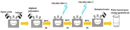
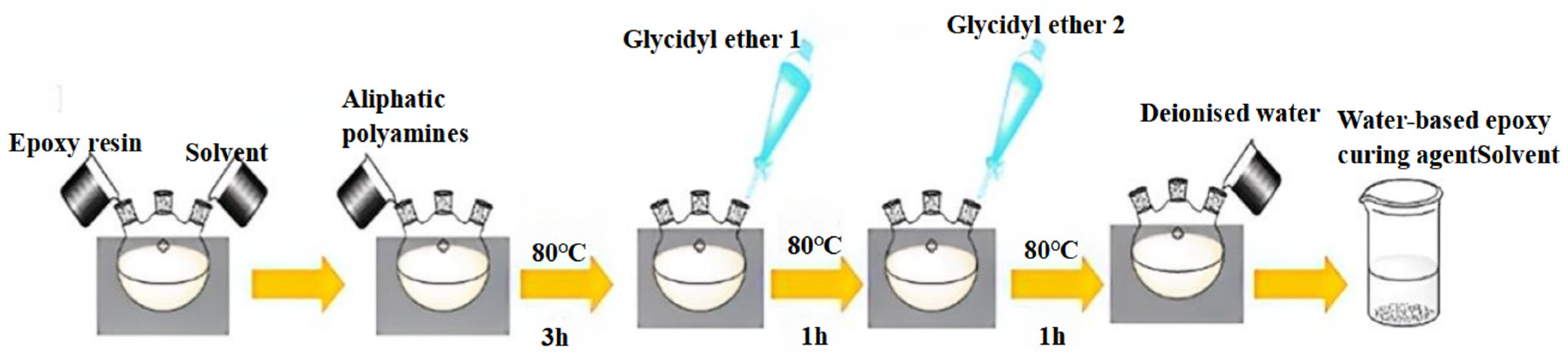
As shown in Figure 1, a measured quantity of E20 epoxy resin was first dissolved in propylene glycol monomethyl ether to form a homogeneous solution under mechanical stirring. An aliphatic polyamine was then introduced into the system; after reacting for a period at 80 °C (for not less than 1.5 h), glycidyl ether 1 was slowly added using a dropping funnel. Once the addition was complete, the system was maintained at the same temperature and allowed to react for a further hour to ensure sufficient grafting of the molecular chains. Glycidyl ether 2 is then added to cap the chains, and finally deionised water is added to dilute the system and adjust its solid content. After thorough mixing, the mixture is cooled to room temperature, yielding a water-based epoxy curing agent with stable dispersion properties.
Figure 1.
Process flow for the preparation of water-based epoxy curing agents.
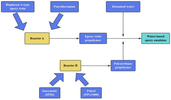
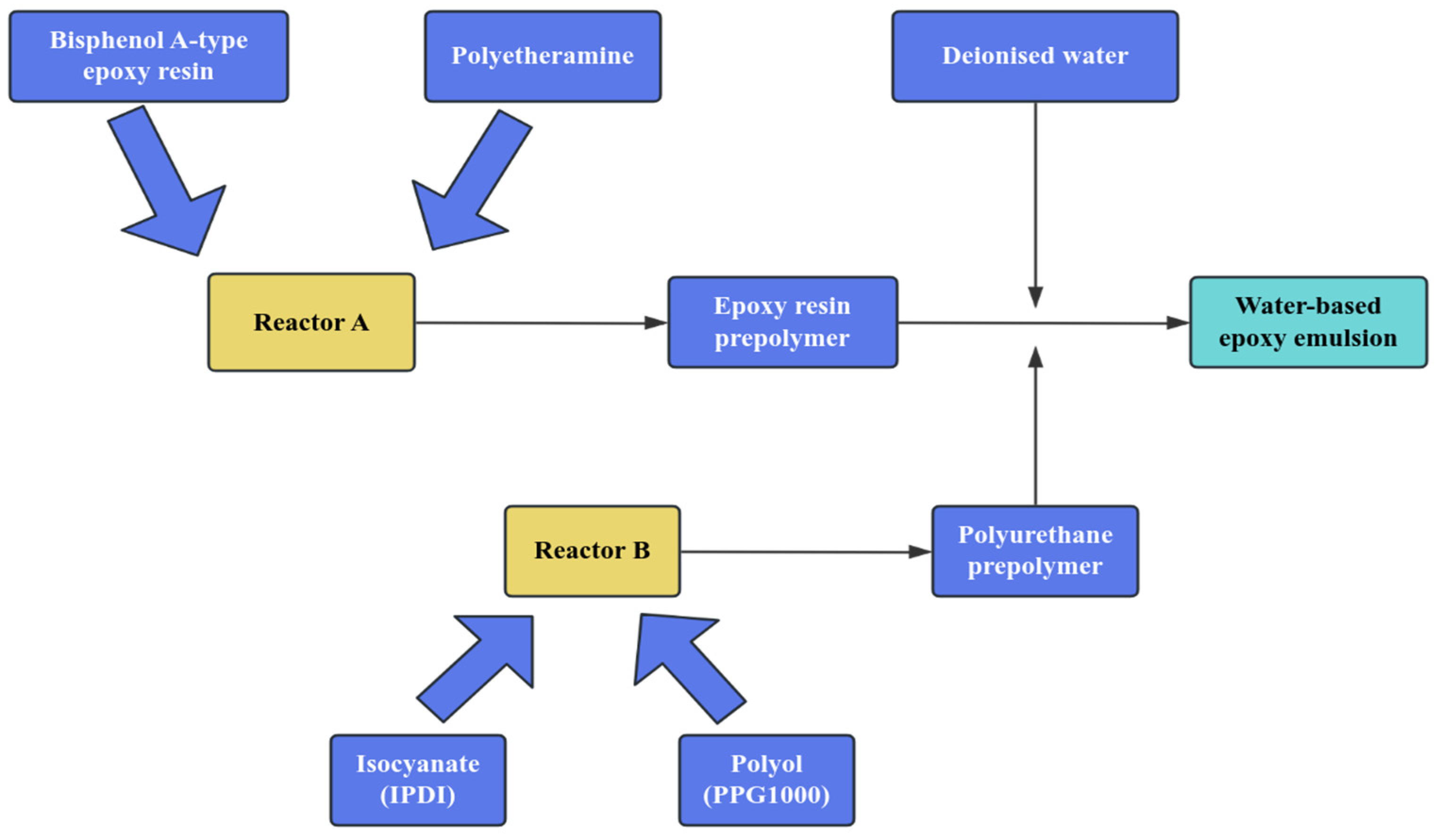
We added the measured quantities of epoxy resin and propylene glycol monomethyl ether to Reactor A. After stirring thoroughly, we added the polyetheramine, raised the temperature to the reaction temperature, and maintained it for a specified period to obtain a water-based epoxy prepolymer. We added the measured quantities of IPDI and PPG1000 to Reactor B. After stirring thoroughly, we added the catalyst, raised the temperature to the reaction temperature, and maintained it for a specified period to obtain a polyurethane prepolymer. Reactor A was cooled to a specific temperature, and the prepared polyurethane prepolymer was added. After maintaining the temperature for the reaction, deionised water was added at a specific stirring speed to induce emulsification, thereby yielding a self-toughening water-based epoxy emulsion—the preparation flowchart is shown in Figure 2.
Figure 2.
Process flow for the preparation of water-based epoxy emulsion.
We placed the water-based epoxy emulsion prepared according to the flowchart in Figure 2 and the water-based epoxy curing agent in a constant-temperature water bath (25 ± 1 °C) in a specific mass ratio, and was stirred until thoroughly mixed. Functional additives (such as levelling agents and defoamers) were introduced simultaneously to eliminate microbubbles generated during mixing and improve the rheological properties of the system. The prepared water-based epoxy emulsion was then poured onto a PTFE plate; after heating and curing for a period of time, a water-based epoxy coating film was obtained.
2.2.2. Preparation of Filler-Based Water-Based Epoxy Coatings
Additives such as wetting agents, dispersants, defoamers, and phthalocyanine blue pigment were added to the homemade water-based epoxy emulsion. The mixture was placed in a disperser and stirred at 500 r/min for 10 min to form a uniform base material. Next, we added inorganic fillers, such as titanium dioxide and precipitated barium sulphate, increased the stirring speed to 1200 r/min, and continued stirring for 1 h to ensure that the inorganic fillers did not agglomerate or settle. Finally, a defoamer was added and stirred at low speed for 10 min to eliminate foam. The resulting solution was weighed out in a specific ratio with a homemade water-based epoxy curing agent and placed in a water bath at 25 °C ± 2 °C for thorough mixing. Subsequently, a silane coupling agent was added at a concentration of 1% by weight, and the mixture was stirred again until uniform. We added an appropriate amount of defoamer to the system and stirred at low speed to eliminate air bubbles. We applied the coating to test specimens and cured them at an elevated temperature. The prepared specimens were used to investigate the effects of filler type and content on corrosion current density, coating thickness, and continuity.
This study utilised a base formulation comprising a self-prepared water-based epoxy emulsion, titanium dioxide (5% by mass of the water-based epoxy emulsion), and precipitated barium sulphate (10% by mass of the water-based epoxy emulsion), to which zinc–iron powder, zinc phosphate, and heavy calcium carbonate powder were added, with the aims of investigating the effects of their types and dosage on the performance of water-based epoxy coatings and identifying cost-effective inorganic fillers that can replace expensive polyaniline/graphene nanocomposites. The formulation ratios for each test group are shown in Table 1, where the percentages in the table represent the mass percentage of the water-based epoxy emulsion, including additives such as wetting agents, dispersants, defoamers, and phthalocyanine blue pigment.
Table 1.
Mixing ratios for water-based epoxy coatings.
2.2.3. Preparation of Steel Bars with Water-Based Epoxy Coating
Using a base formulation comprising a self-prepared water-based epoxy emulsion (EP), titanium dioxide (Ti), and precipitated barium sulphate (Ba), a water-based epoxy coating for reinforcing bars incorporating 0.3% graphene–polyaniline composite nanomaterials (PAG) was used as the control group, with a water-based epoxy coating containing a silane solution as the primer. Based on the experimental results, a water-based epoxy coating containing 1% silane coupling agent (GW) and 10% zinc phosphate (ZP) was selected as the intermediate coat, whilst a water-based epoxy coating containing fly ash microspheres and polystyrene microspheres was selected as the top coat. HRB400 ribbed steel bars, 400 mm in length and 16 mm in diameter, were selected as test specimens for the cold bending test. The test formulations for each group are shown in Table 2; each group comprised three steel bars, with a total of six groups.
Table 2.
Mix proportions for the coating used in cold bending tests on epoxy-coated reinforcing bars.
2.2.4. Preparation of Test Specimens for the Tensile Properties of Water-Based Epoxy-Coated Reinforcing Bars
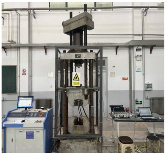
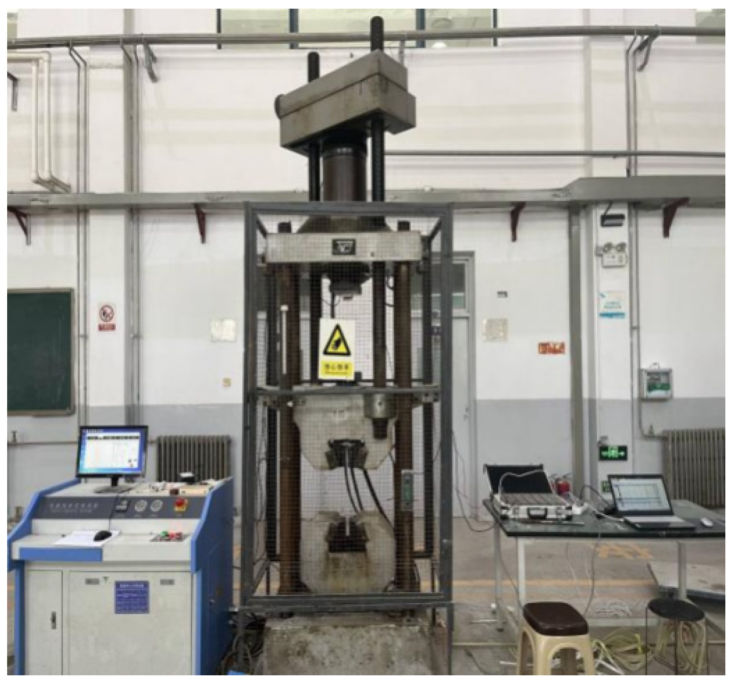
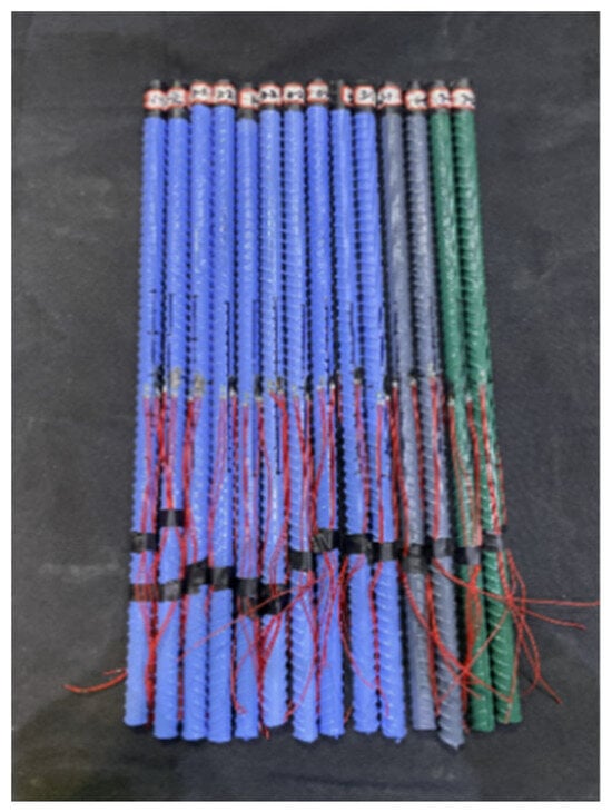
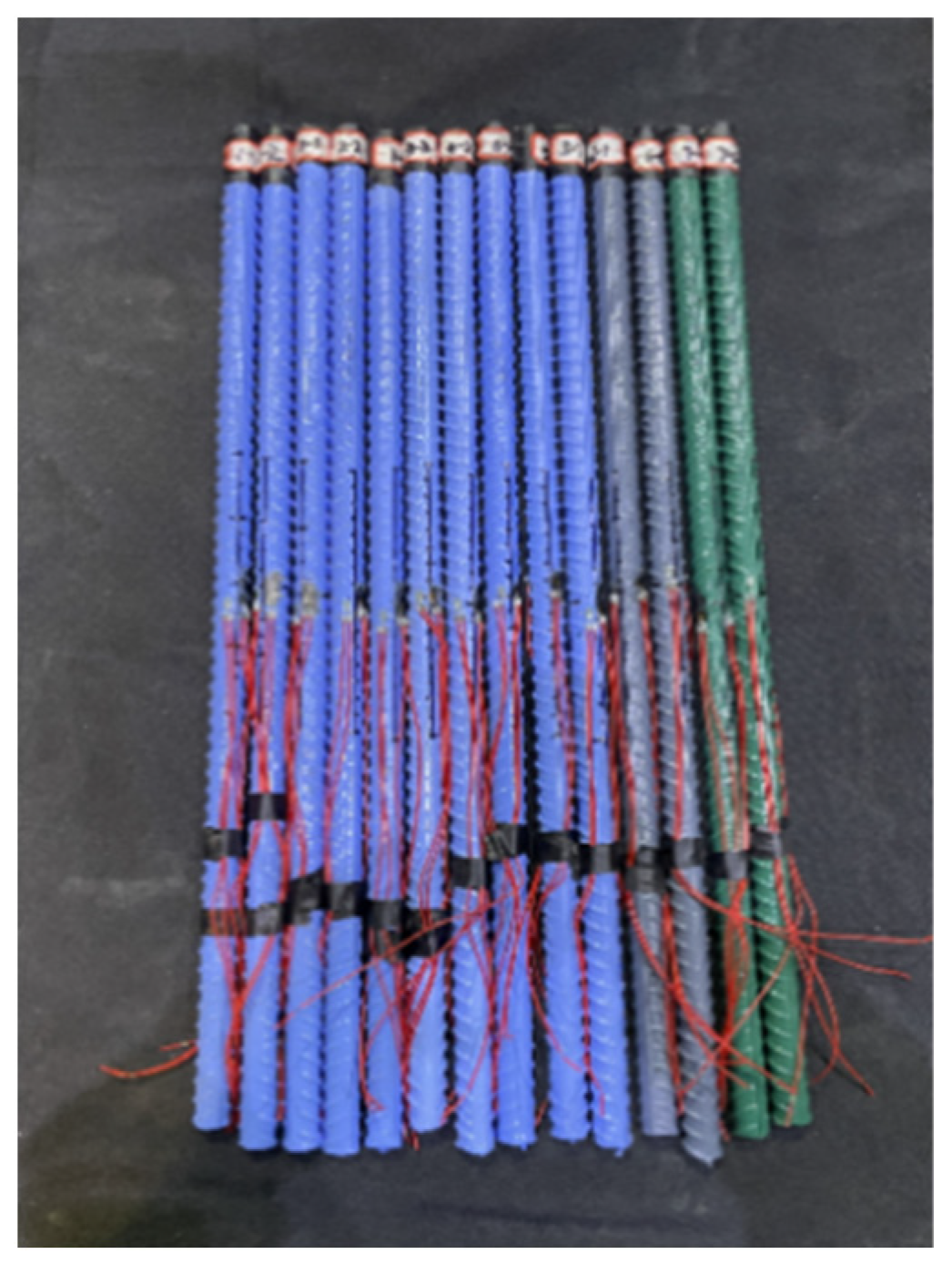
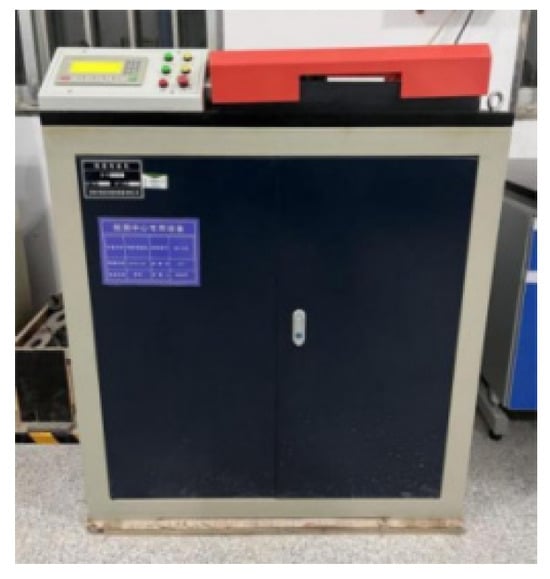
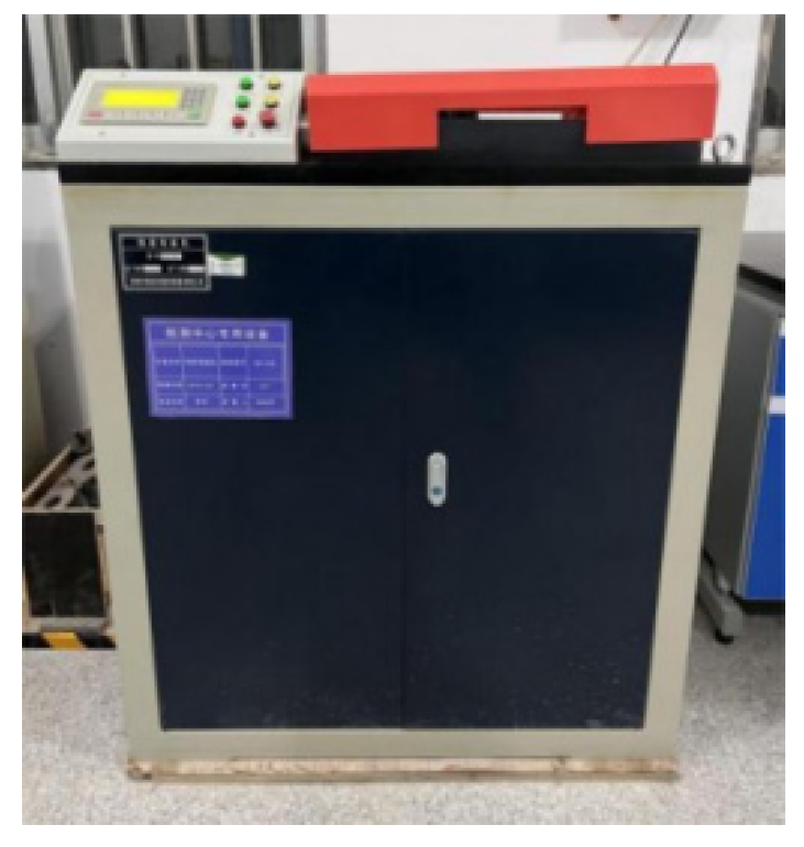
HRB400 ribbed steel bars, 600 mm in length and 16 mm in diameter, were selected, and an epoxy coating was prepared according to the proportions given in Table 2. Strain gauges were affixed to the surface of the coated reinforcing bars. On the opposite side, symmetrical to the gauge, a small section of the coating was ground away using an angle grinder. The exposed surface of the reinforcing bar was cleaned with anhydrous ethanol, left to dry, and then the strain gauge was bonded to the bar using adhesive. Once the adhesive had completely dried, testing was carried out using a tensile testing machine (as shown in Figure 3). The prepared specimens are shown in Figure 4.
Figure 3.
Tensile testing machine.
Figure 4.
Tensile test specimen of coated reinforcing steel.
2.2.5. Preparation of Test Specimens for Experiments on Epoxy-Coated Reinforcing Bars Using the Digital Speckle Correlation Method
The deformation of epoxy-coated reinforcing bars was tested using the speckle method on the specimens listed in Table 2. For the test, 600 mm lengths of 16 mm diameter HRB400 ribbed reinforcing bars were selected. Following the preparation of the coated reinforcing bars, a speckle pattern was applied to their surfaces using a marker pen. The spots were required to be of moderate size, densely distributed, and arranged in a random pattern to avoid clustering, ensuring that the discrete spots remained clearly distinguishable. Subsequently, the software Ncorr(v1.14.0.0), which utilises a two-dimensional digital image correlation algorithm, was employed to analyse the longitudinal strain (Eyy).
2.3. Test Methods
2.3.1. Test Method for the Tensile Properties of the Coating Film
We conducted tensile tests on the coating film in accordance with the provisions of the national standard GB/T 1040.3-2006 [22]. During sample preparation, we ensured that the thickness of the test specimens was kept below 1 mm. Subsequently, we placed the prepared specimens in a constant-temperature chamber for curing. Once curing was complete, we mounted the specimens in the fixtures of the UTM 4103 universal testing machine. At this stage, we ensured that the centreline of the specimen aligned with the centreline of the fixture and adjusted the gauge length to match the length of the specimen. We commenced the tensile test at a test speed of 5 mm/min. For each group, five parallel samples were prepared according to this ratio, and the results were calculated as the average of five test runs.
2.3.2. Testing of Electrochemical Corrosion Current Density
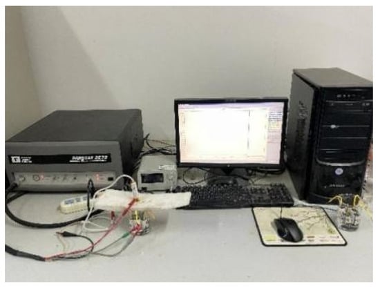
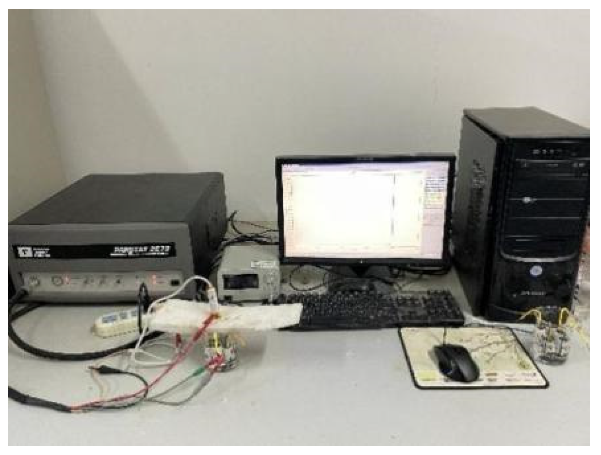
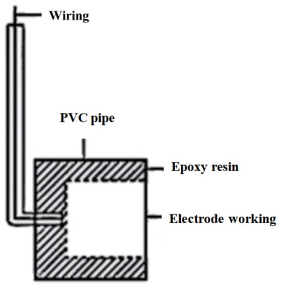
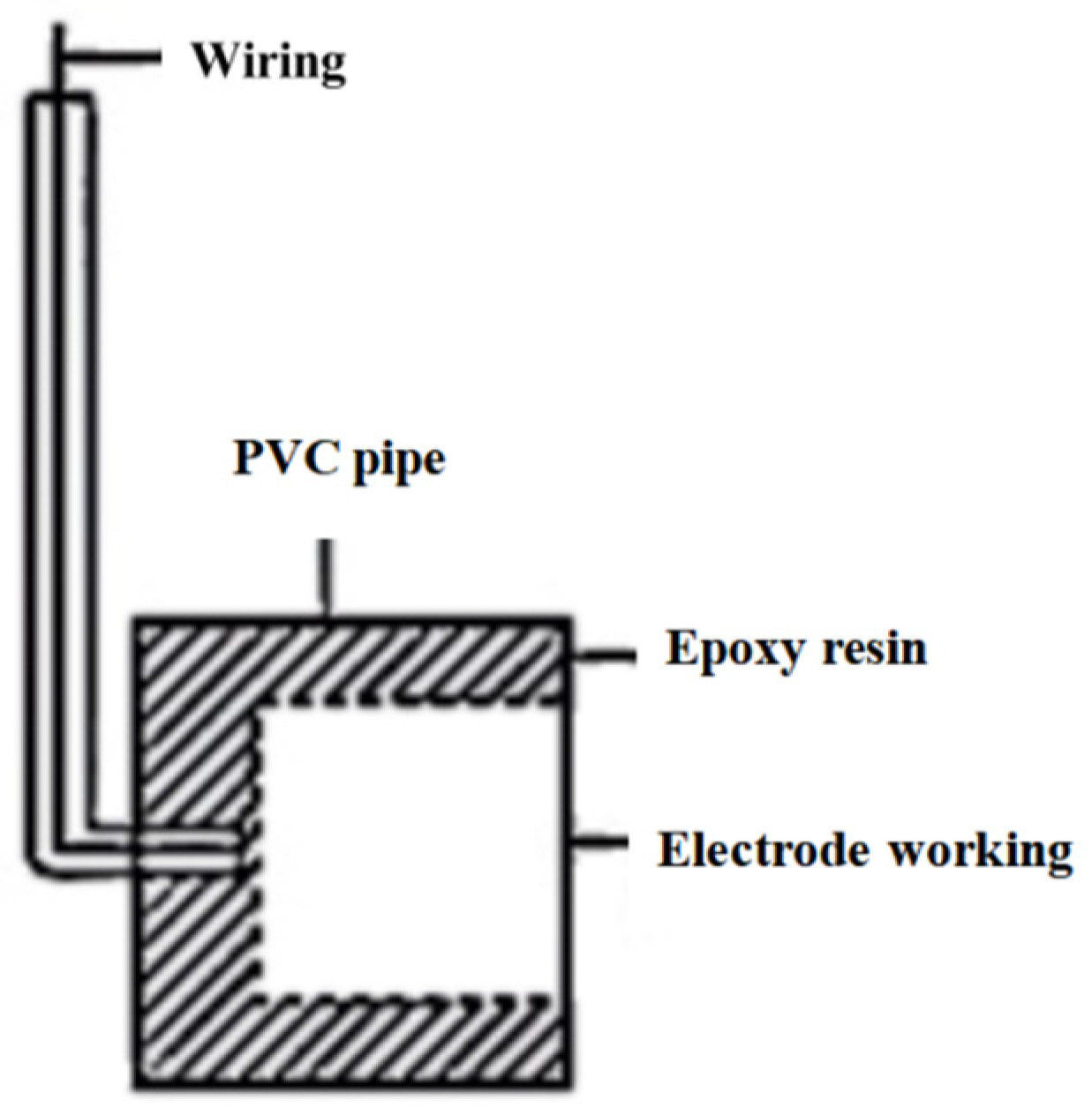
The determination of electrochemical corrosion current density was carried out in accordance with the provisions of Technical Specification T/CECS 874-2021 [23]. Testing was performed using a PARSTAT 2273 electrochemical workstation (as shown in Figure 5), with the three-electrode system configured as follows: the working electrode was fabricated from HPB300 smooth-surfaced reinforcing bars prepared in-house; a platinum sheet electrode served as the auxiliary electrode; and a saturated calomel electrode acted as the reference electrode (as shown in Figure 6). During specimen preparation, the surface of the steel bar was thoroughly cleaned using cotton balls soaked in anhydrous ethanol. After allowing it to dry naturally, a water-based epoxy coating was applied to the working surface area by immersion. To ensure complete coating coverage, areas with uneven application were smoothed using a glass rod. Three independent electrode specimens were prepared for each formulation, and the corrosion current density was taken as the average of three measurements.
Figure 5.
Princeton electrochemical workstation.
Figure 6.
Preparation of steel bar electrode specimens.
It should be noted that, in this study, HPB300 smooth reinforcing bars were used as the working electrode substrate for the electrochemical tests, whereas HRB400 ribbed reinforcing bars were used for the cold bending and tensile tests; there are differences in the surface morphology between the two. Smooth-surfaced reinforcing bars were selected for the electrochemical tests primarily because their smooth surfaces allow for more uniform coating thickness and higher reproducibility after coating application, facilitating precise control of the effective working area and thereby yielding highly comparable corrosion current density data; conversely, HRB400 ribbed steel bars were selected for the cold bending and tensile tests to reflect real-world engineering applications—this grade of steel is the predominant material used in load-bearing components of concrete structures—thus investigating the cold bending performance and deformation coordination of water-based epoxy coatings on ribbed steel bars holds greater engineering significance.
Furthermore, the specific parameters for this experiment are as follows: the effective working area of the working electrode was precisely controlled to 1.0 cm2 by sealing the edges with Parafilm; the test solution was a 3.5 wt.% NaCl solution, with the temperature maintained at 25 ± 1 °C using a constant-temperature water bath; and polarisation curves were measured using a PARSTAT2273 electrochemical workstation (This instrument is manufactured by Princeton Applied Research, a subsidiary of the AMETEK Group based in Oak Ridge, TN, USA), with a potential scan range of −250 mV to +250 mV relative to the open-circuit potential, a scan rate of 0.1667 mV/s, and a data acquisition interval of 1 s. Prior to measurement, the working electrode was immersed in the test solution for 30 min to ensure the stability of the open-circuit potential; the above procedure was carried out in accordance with the ASTM G59 standard [24].
2.3.3. Testing the Thickness of Coated Reinforcing Bars
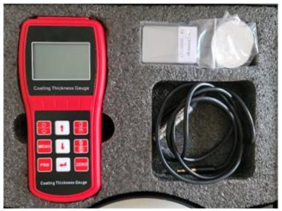
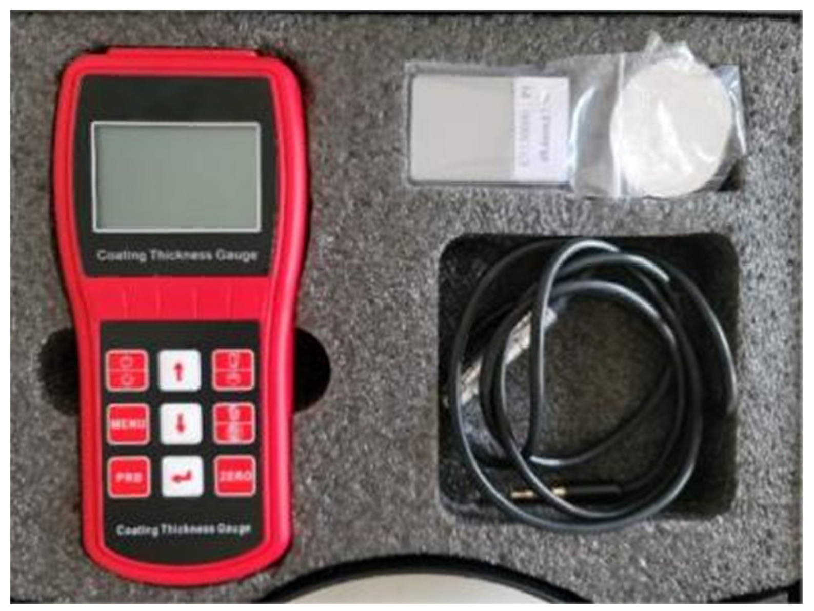
HRB400 ribbed steel bars, 300 mm in length and 16 mm in diameter, were selected for coating thickness tests. When preparing water-based epoxy-coated reinforcing bars, the rust on the surface of the bars was first ground away. After wiping the bars with anhydrous ethanol, they underwent preheating in an oven at 40 °C until the surface temperature reaches 40 °C, at which point the coating application process commenced. Following application, the bars were cured in the oven for 6 h at 40 °C and 6 h at 60 °C. The inspection of coating thickness was carried out in accordance with the relevant provisions of the reference standard GB/T 25826-2022 [25]. Figure 7 shows the coating thickness tester for steel bars. For each reinforcing bar, 10 measurement points were selected at regular intervals along its length, and the results were taken as the average of the 10 measurements.
Figure 7.
Coating thickness gauge.
2.3.4. Testing the Continuity of the Coating Surface
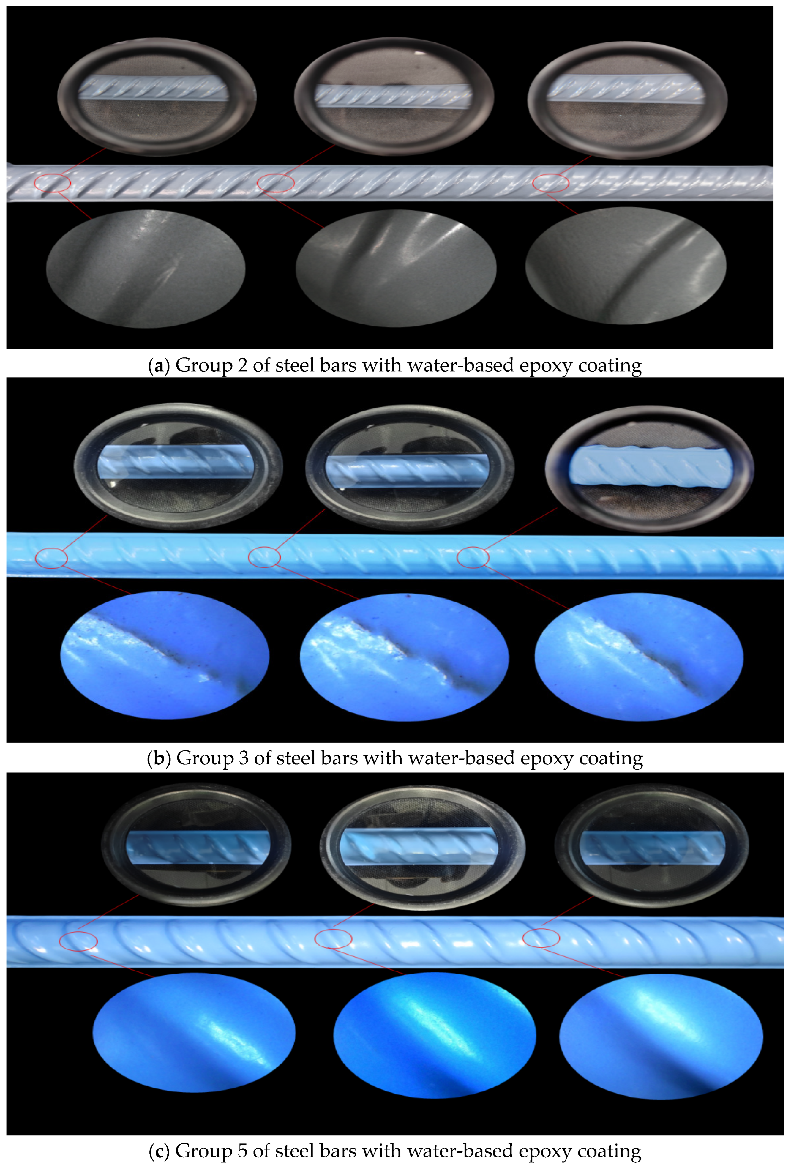
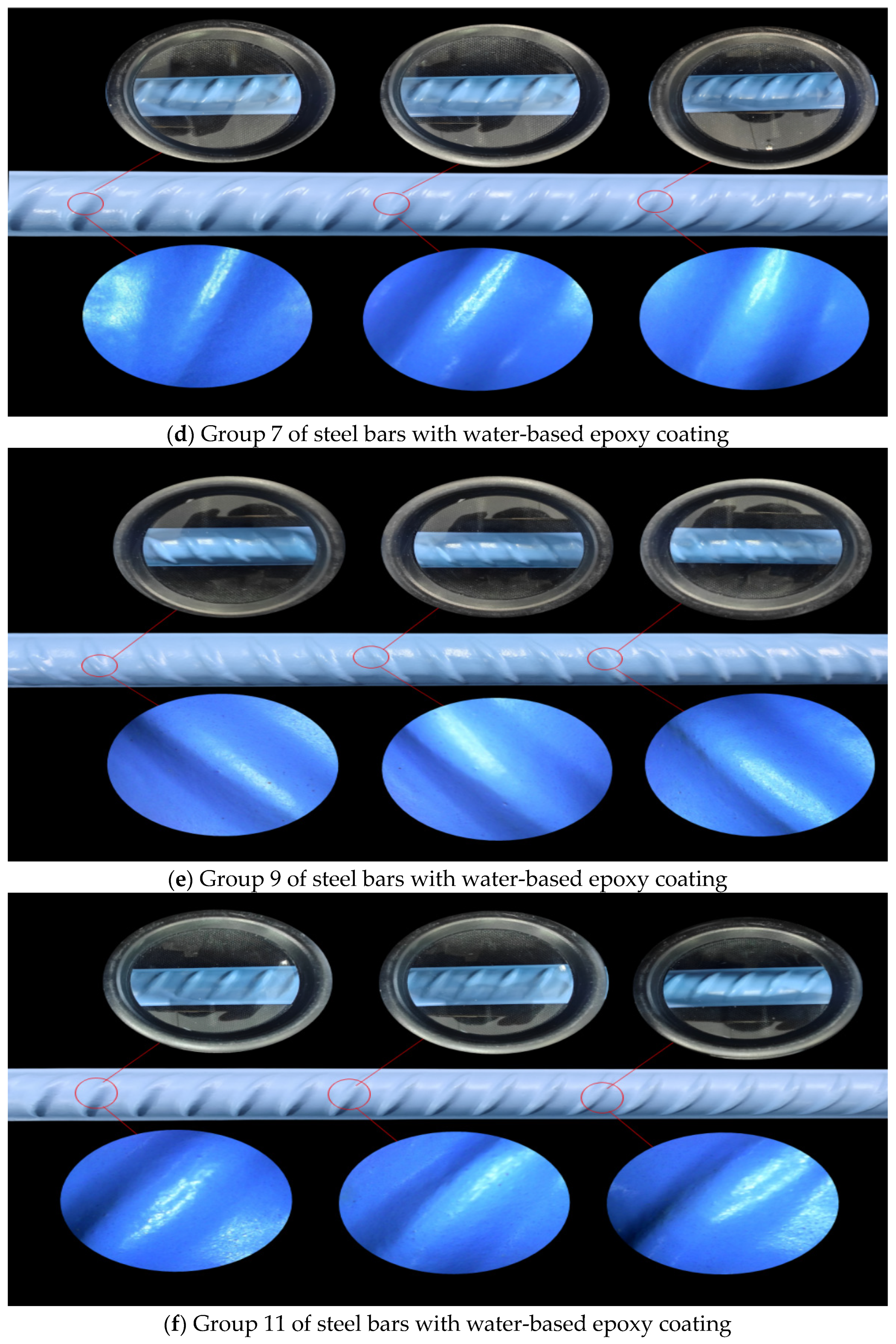
Tests were conducted in accordance with GB/T 25826-2022 [25]. Upon curing, the surface of the coated reinforcing bars must meet the relevant flatness requirements, indicating the absence of defects such as pinholes or cracks. No more than two pinholes should be present per metre of coated reinforcing bar surface. The reinforcing bars used in the test were HRB400 ribbed bars, 300 mm in length and 20 mm in diameter. After the test specimens were formed, the surfaces of the coated reinforcing bars were examined using magnifying glasses with 10× and 500× magnification.
2.3.5. Testing of the Cold Bending Properties of Epoxy-Coated Reinforcing Bars
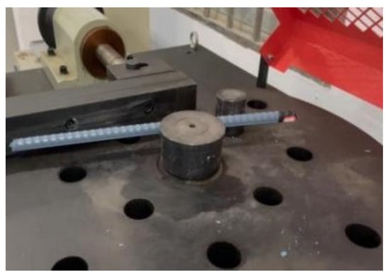
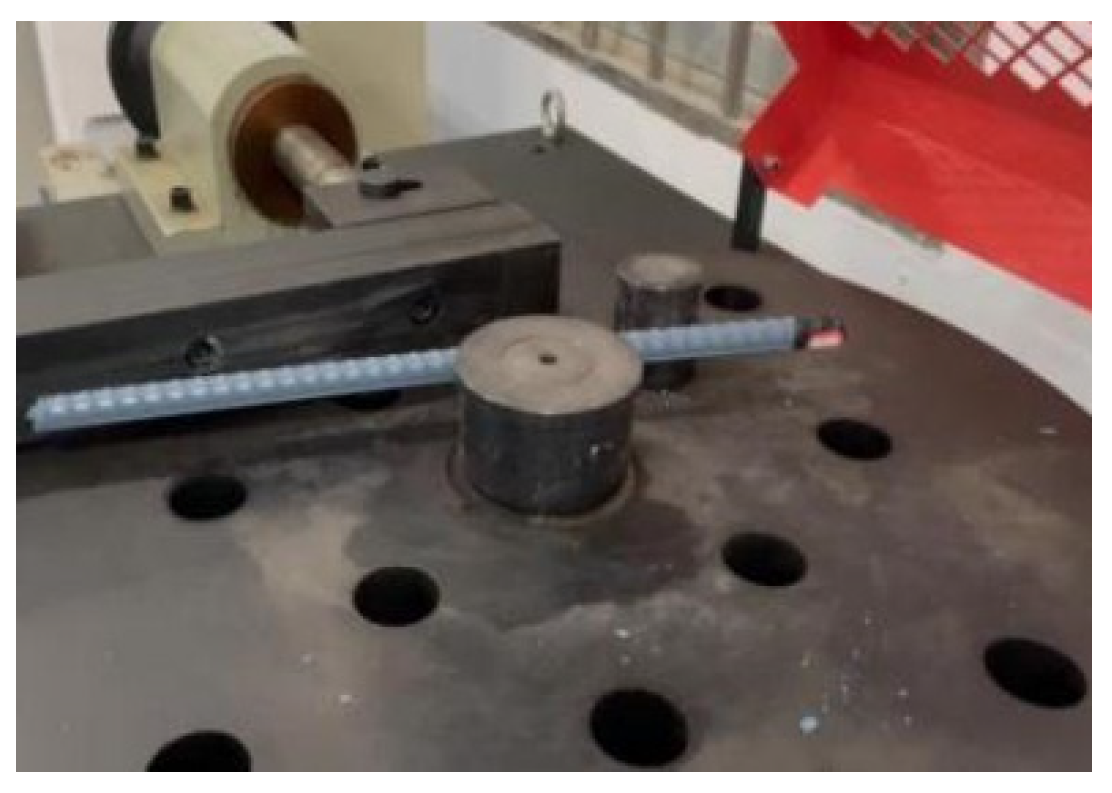
The steel bar specimens were placed in an environment maintained at 23 °C ± 5 °C, and cold bending tests were conducted using a steel bar bending machine. The bending operation was performed on the bending machine at a constant rate. The test was terminated when a bending angle of 180° was reached, after which the cracking and spalling of the coating surface were examined. Figure 8 illustrates the specific construction of the bending machine, whilst Figure 9 shows the positioning of the steel bars—for each mix design, three reinforcing bars were tested.
Figure 8.
Cold bending testing machine for reinforcing bars.
Figure 9.
Placement of coated reinforcing bars.
2.3.6. Method for Calculating the Post-Fracture Elongation of Steel Bars Coated with Water-Based Epoxy
- (1)
- Tests shall be conducted in accordance with the provisions of Chapter 6 of GB/T 28900-2022 ‘Test Methods for Steel for Reinforced Concrete’ [26]; the post-fracture elongation shall be calculated using Equation (1):where A—elongation of the reinforcing bar at coating cracking, %; L—gauge length of the reinforcing bar at coating cracking, mm; and L0—original gauge length of the reinforcing bar, mm.
- (2)
- During the tensile test of the coated reinforcing bar, the test shall be stopped when visually observable cracking of the coating is observed. After the test, a stress–strain curve for the entire tensile process shall be plotted to analyse the deformation coordination between the coating and the reinforcing bar.
For each mix design, three test specimens are tested, and the results are based on the representative values from the three tests.
2.3.7. Digital Speckle Correlation Method Test
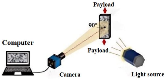
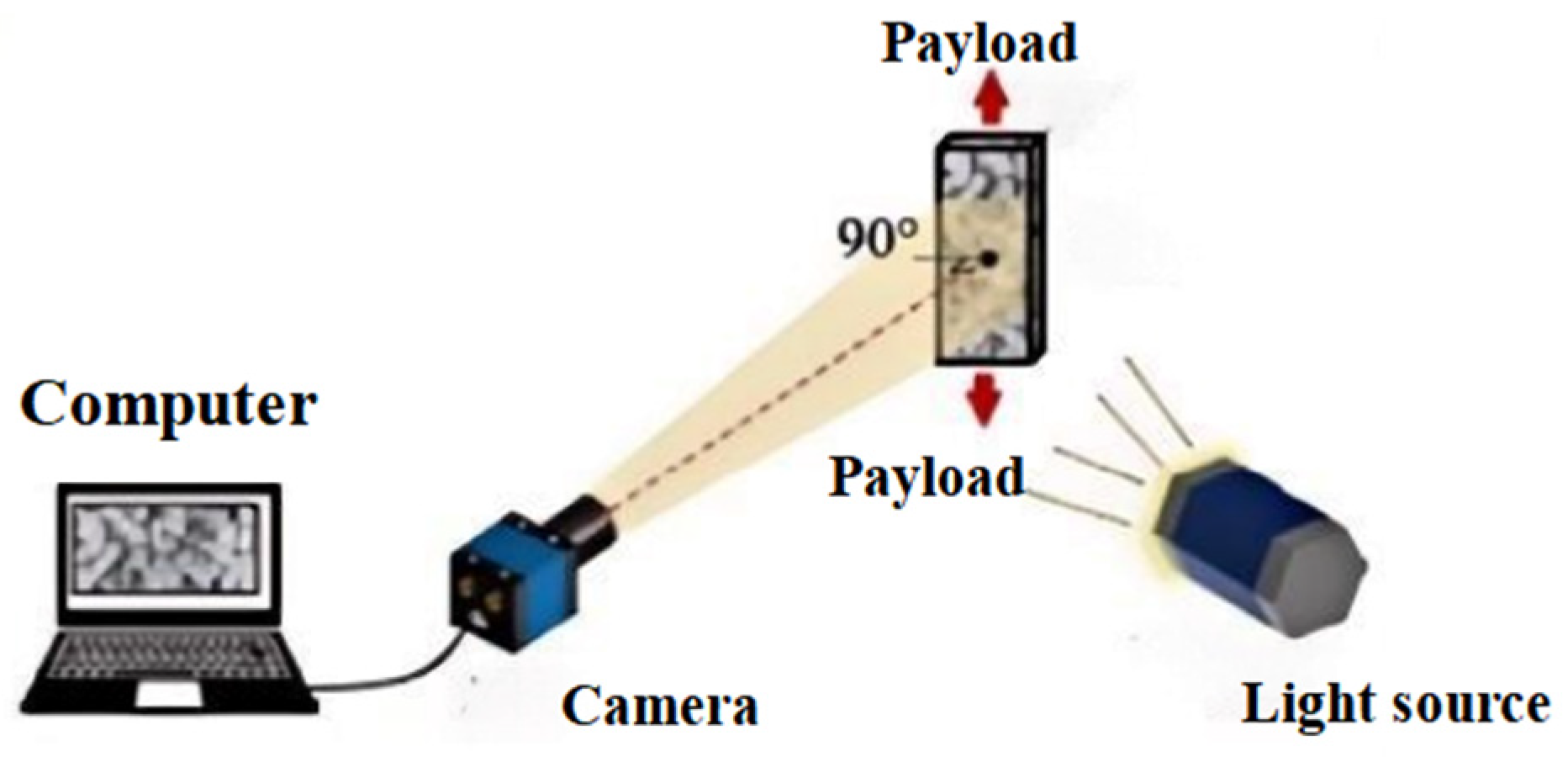
Digital Speckle Correlation Method (DSCM) is a non-contact optical measurement technique widely used to characterise surface deformation or topographical changes in materials. This method is based on the speckle phenomenon—the randomly distributed pattern of light and dark spots produced when light waves pass through a non-uniform medium. By analysing changes in these patterns at different times or under different conditions, information regarding the deformation of the object’s surface can be deduced [27,28]. The fundamental principle is as follows: a camera records speckle images of the object’s surface before and after deformation. By comparing and analysing the two images, and utilising digital image processing and correlation algorithms, the displacement field of the speckle pattern is calculated, thereby determining the distribution of surface deformation [29]. The specific experimental procedure is as follows: a light source illuminates the surface under test, a camera captures the image, and the image data are then transmitted to a computer via a USB interface. First, the initial speckle image of the object in the unloaded state is acquired; subsequently, the deformed speckle image is acquired under loading conditions. By performing a correlation analysis on the two images, the surface displacement field data is ultimately obtained.
In this study, a tensile testing method was employed to investigate the deformation behaviour of the coating on coated steel bars during the tensile process, with the longitudinal deformation analysis carried out using Ncorr software [30]. The specific experimental procedure is shown in Figure 10. For each mix design, three test specimens are tested, and the results are based on the representative values from the three tests.
Figure 10.
Measurement using digital image correlation methods.
Digital Speckle Correlation Method (DSCM) analysis was performed using the Ncorr software (an open-source MATLAB toolbox v1.14.0.0), and the main DIC parameter settings are shown in Table 3. The correlation criterion employed was zero-mean normalised cross-correlation.
Table 3.
DIC test parameter settings.
3. Results and Discussion
3.1. Effect of the Coating Film on Tensile Properties
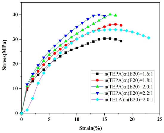
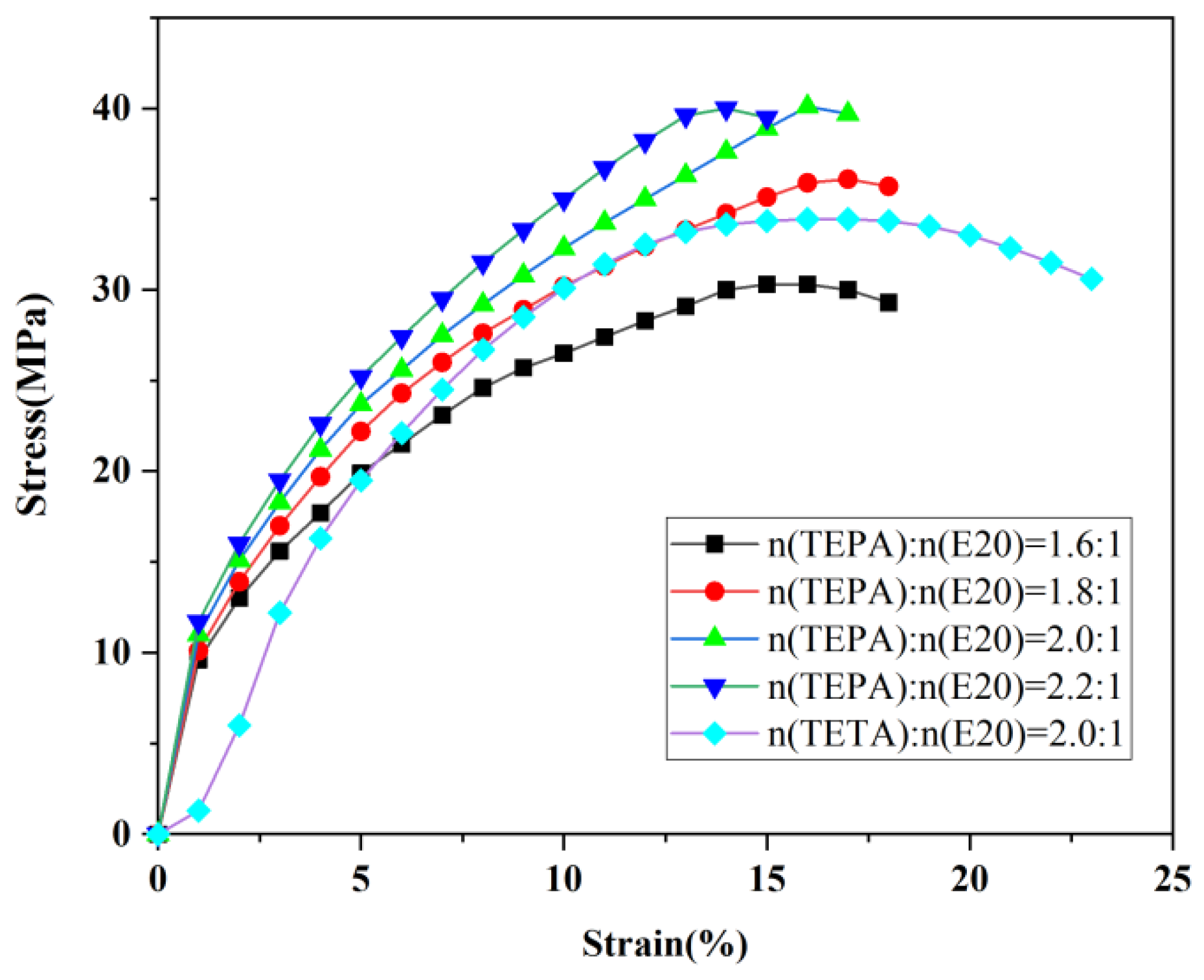
Water-based epoxy curing agents were prepared using different types and loading levels of aliphatic polyamines (TEPA, TETA). These were blended with water-based epoxy emulsions to produce coating films; the trends in their tensile properties following heat curing are shown in Figure 11. The experiments demonstrated that as the TEPA content increased (with the molar ratio of TEPA to E20 rising from 1.6:1 to 2.2:1), the tensile strength of the coating film increased significantly, whilst the elongation at break exhibited a conversely decreasing trend. Specifically, when n(TEPA):n(E20) = 1.6:1, the tensile strength of the coating film was 30.25 MPa, with an elongation at break of 19.4%; when increased to n(TEPA):n(E20) = 2.0:1, the tensile strength rose to 40.25 MPa (a 33.05% increase compared to the 1.6:1 group), whilst the elongation at break decreased slightly to 17.33%; and further increasing to n(TEPA):n(E20) = 2.2:1 resulted in tensile strength remaining on par with the 2.0:1 group, but the elongation at break fell to 14.1%, indicating that excessive amine incorporation may pose a risk of brittle fracture. A cross-comparison revealed that, under the same molar ratio (n(polyamine):n(E20) = 2.0:1), the tensile strength of the TEPA-based curing agent coating was 18.3% higher than that of the TETA-based system, confirming that the polyamine groups in the TEPA molecule can enhance the density of the cross-linked network. Although the strength of the 2.2:1 group was similar to that of the 2.0:1 group, its elongation at break deteriorated significantly, whereas the 2.0:1 group maintained a high strength (>40 MPa) whilst retaining an elongation of over 17%. Therefore, n(TEPA):n(E20) = 2.0:1 was selected as the optimal ratio for subsequent research, with the aim of balancing the material’s mechanical properties.
Figure 11.
Effect of different types and loading levels of aliphatic polyamines on the tensile properties of the coating film.
3.2. The Effect of Curing Process and Solids Content on the Tensile Properties of the Coating Film
Water-based epoxy curing agents with different solid contents (42%, 45%, and 50%) were blended with water-based epoxy emulsions in specific proportions. After homogenisation in a constant-temperature water bath at 25 ± 2 °C, the mixture was applied to form a film, cured at 40 °C for 6 h, and then heated to 60 °C for a further 2–8 h. As revealed by Table 4, Table 5 and Table 6, which present the tensile properties of coatings with different solid contents at various curing times, a significant inverse relationship was observed between tensile strength and elongation at break as the curing time at 60 °C increased. Taking the 42% solid content system as an example, when the post-curing time was increased from 2 h to 6 h, the tensile strength rose from 10.79 MPa to 39.76 MPa, whilst the elongation at break decreased from 35.85% to 17.33%. Upon further extension to 8 h, the strength increased only marginally by 1.8% (reaching 40.48 MPa), whilst the elongation at break fell further to 12.67%. This indicates that excessive cross-linking leads to brittle degradation, thereby establishing a 6 h curing period at 60 °C as the optimal process window. Further investigation of the effect of solids content under the optimised 6 h curing conditions revealed that when the solids content was increased from 42% to 45%, the elongation at break increased by 15% to 19.93%, whilst the tensile strength remained at 39.76 MPa; however, when the solids content was further increased to 50%, the increase in elongation at break was only 7%. A moderate increase in solids content can improve coating density by reducing microporous defects; however, if the solids content is too high (>45%), the viscosity of the system increases dramatically, making defoaming difficult and actually increasing the risk of internal defects. In summary, using a solids content of 45% in combination with a curing process of 60 °C for 6 h achieves a good balance between a tensile strength of 39.76 MPa and an elongation at break of 19.93%.
Table 4.
Effect of different curing times in a 60 °C oven on the tensile properties of the coating film (typical solid content: 42%).
Table 5.
Effect of different curing times in a 60 °C oven on the tensile properties of the coating film (typical solid content: 45%).
Table 6.
Effect of different curing times in a 60 °C oven on the tensile properties of the coating film (typical solid content: 50%).
Although this study did not involve thermal analysis tests such as DSC, the existing tensile data can be reinterpreted from the perspective of classical polymer theory. According to rubber elasticity theory and the Flory–Rehner theory, cross-linking density (νe) is the key parameter determining the mechanical properties of the polymer network, as tensile strength increases with rising νe, whilst elongation at break decreases—the two exhibit a typical antagonistic relationship [31]. The data in Table 4, Table 5 and Table 6 are fully consistent with this pattern, which is attributed to the fact that extended curing time promotes the epoxy-amine cross-linking reaction, thereby increasing the cross-linking density.
Although it is not possible to directly measure the absolute cross-linking density, the relative change in tensile modulus can be used to provide a semi-quantitative indication of the trend in cross-linking density. The coating film obtained using the optimised process (45% solids content, 60 °C/6 h) achieved a good balance between tensile strength and elongation at break, indicating that the cross-linking density under these conditions lies within an appropriate range; that is, it was sufficient to form an effective network to bear stress, yet not so high as to excessively restrict the movement of molecular segments and cause brittle fracture. Subsequent studies will utilise DSC and the swelling method to determine the absolute cross-linking density, with the aim of establishing a comprehensive quantitative relationship of ‘formulation–cross-linking structure–mechanical properties’.
3.3. The Effect of Fillers and Additives on the Properties of Water-Based Epoxy Coatings
3.3.1. Analysis of Electrochemical Corrosion Current Density Results
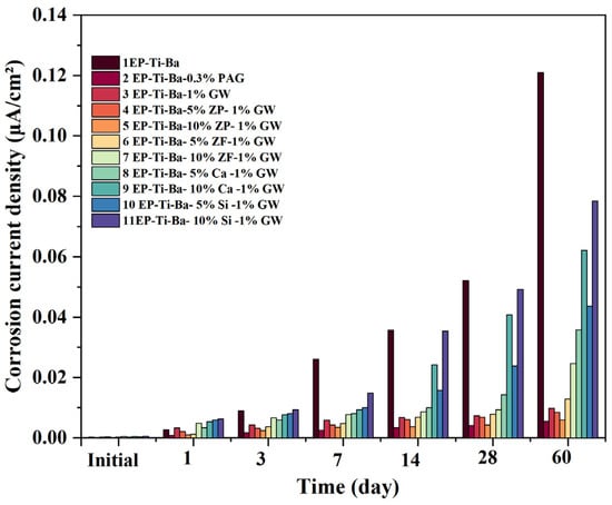
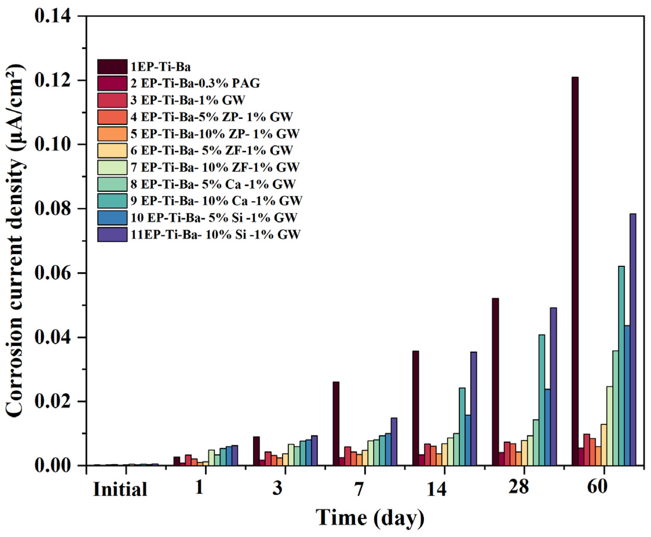
Steel electrodes coated with a layer of paint were immersed in a 3.5 wt% NaCl solution for 60 days, and the corrosion current density was measured at various time points. Figure 12 illustrates the trends in corrosion current density for water-based epoxy coatings containing different types and levels of fillers. The experimental results indicate that the epoxy coating without any added fillers (control group 1) exhibited a corrosion current density of 0.121 μA/cm2 after 60 days of immersion, demonstrating limited protective performance; conversely, the silane-modified group 3, to which 1% silane solution was added, exhibited a significant reduction in corrosion current density to 0.00982 μA/cm2, a decrease of 92%, demonstrating that silane substantially enhances coating adhesion by strengthening the coating–metal interface bond, thereby improving corrosion resistance. The coating containing 0.3% PAG exhibited the best protective performance, with a corrosion current density of 0.00538 μA/cm2 after 60 days; the polar groups in its molecular chains formed a cross-linked network with the epoxy resin, effectively blocking the penetration pathways of the corrosive medium; meanwhile, the coating modified with silane and further supplemented with 10% zinc phosphate exhibited a corrosion current density of 0.00589 μA/cm2 after 60 days, with protective performance comparable to that of the PAG-modified group. This indicates that the flake-like structure of zinc phosphate creates a maze effect within the coating to retard Cl− diffusion, whilst its corrosion-inhibiting function passivates the metal surface.
Figure 12.
Effect of filler type and content on the corrosion current density of the coating.
The contribution of fillers to the corrosion resistance of coatings is manifested not only through physical barrier effects but also through the regulation of the chemical environment at the coating–metal interface. Djenaoucine et al. employed a multi-technique approach combining open-circuit potential (OCP), electrochemical impedance spectroscopy (EIS), and linear polarisation resistance (LPR) to conduct a one-year electrochemical monitoring study on reinforced concrete incorporating graphene oxide under wet–dry cycling conditions [32]. The study found that graphene oxide not only delays the transport of corrosive media to the reinforcing bars by optimising the microstructure of the concrete and reducing chloride ion permeability, but it also forms a denser passivation layer on the surface of the reinforcing bars, thereby achieving long-term corrosion inhibition. This dual mechanism of ‘matrix densification’ and ‘interface passivation layer’ provides an important reference for understanding the combined effect of silane coupling agents and zinc phosphate in this study. In this study, the silane coupling agent enhanced the adhesion at the coating/reinforcing bar interface, whilst the corrosion-inhibiting function of zinc phosphate may also involve the formation of a protective phosphate layer on the steel surface, which is similar to the interfacial passivation mechanism of graphene oxide.
It should be noted that corrosion current density is merely one of the key indicators for evaluating the corrosion protection performance of a coating; however, this single indicator is insufficient to fully reflect the long-term protective behaviour of the coating in harsh marine environments. According to a review by Caldona et al. [33], open-circuit potential (OCP), electrochemical impedance spectroscopy (EIS), and dynamic potential polarisation curves are the three most commonly used electroanalytical techniques for assessing the corrosion protection performance of polymer coatings. Among these, EIS can quantify the coating resistance and capacitance through equivalent circuit fitting, thereby providing insights into key factors, such as electrolyte penetration and the adhesion state at the coating/metal interface; likewise, OCP can monitor dynamic changes in the reaction resistance at the coating/substrate interface, whilst polarisation curves can quantitatively evaluate the coating’s barrier efficiency and changes in corrosion rate.
Furthermore, the corrosion testing in this study consisted solely of static full-immersion tests in a 3.5% NaCl solution. Although the method for assessing durability based on corrosion current density, as set out in the association standard T/CECS 874-2021 [23], was followed, there remains a significant discrepancy compared with real marine environments (particularly the alternating wet and dry conditions in the intertidal zone, temperature variations, fluctuations in chloride ion concentration, and the coupled effects of mechanical loads). A 60-day immersion cycle can only reflect the short-term barrier performance of the coating under stable conditions and cannot be directly extrapolated to its long-term service behaviour in actual engineering applications. Therefore, the aforementioned corrosion current density data should primarily be regarded as a relative indicator for the selection of filler formulations.
3.3.2. Test Results and Analysis of Coated Reinforcing Bar Thickness
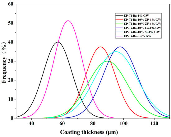
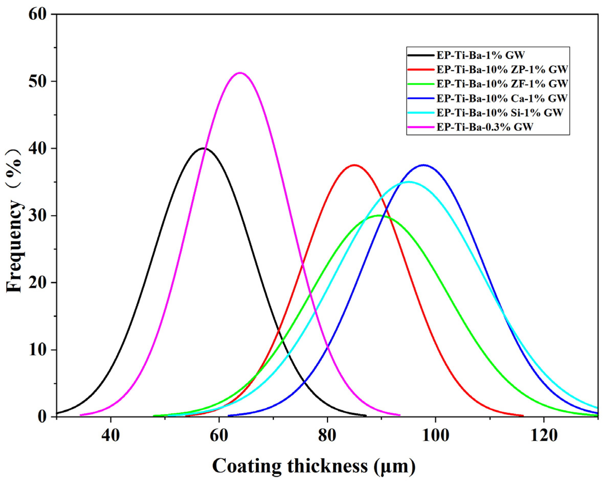
Coating thickness is a key parameter in balancing the corrosion resistance of reinforcing bars with their bond and anchorage performance in concrete; a coating that is too thin is likely to lead to protective failure, whilst one that is too thick will weaken mechanical interlock [34,35]. In accordance with the provisions of GB/T 25826-2022 ‘Epoxy-coated Reinforcing Bars for Reinforced Concrete’ [25], in harsh corrosive environments such as marine chloride or de-icing salt, the average thickness of the epoxy coating on reinforcing bars with a diameter of ≥20 mm must reach 220–400 µm; therefore, it is necessary to precisely control the coating thickness and its uniformity by optimising the type and dosage of fillers. Figure 13 illustrates the thickness distribution of coating-modified steel bars using different fillers. The test results obtained using a coating thickness gauge on single-layer coated specimens indicate that the average coating thickness was only 57 µm when 1% amino silane coupling agent was added; this is because the silane reduced the viscosity of the system, resulting in insufficient coverage of the coating on the steel bar surface, while the average thickness increased to 70 µm upon the addition of 0.3% PAG, as its thickening effect effectively improved the flow properties. The average thickness of coatings containing 10% zinc phosphate and 10% zinc–iron powder was 84 µm and 90 µm, respectively, with both achieving uniform coverage through optimised rheological properties; conversely, coatings containing 10% heavy calcium carbonate powder or 10% quartz powder reached thicknesses of 95 µm and 98 µm, respectively, as the larger particle size of the fillers tended to cause agglomeration, leading to localised accumulation and increased thickness. For zinc-phosphate-modified coatings with excellent protective performance, the appropriate film-forming scheme involves a three-coat application process, resulting in a cumulative coating thickness of over 220 µm [36].
Figure 13.
Distribution of coating thickness on coated reinforcing bars using different fillers.
3.3.3. Testing the Continuity of Coated Reinforcing Bars
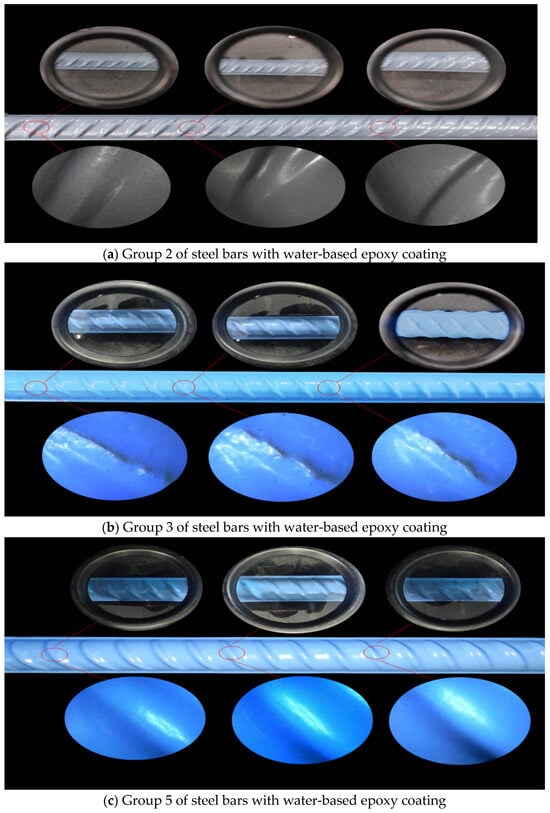
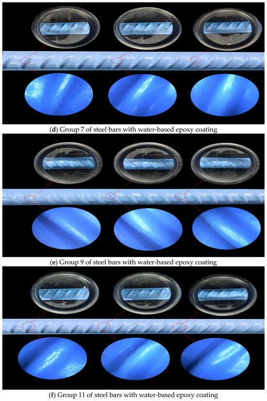
Observation of the surface morphology of water-based epoxy coatings on 20 mm diameter HRB400 ribbed steel bars at 10× and 500× magnification (as shown in Figure 14) revealed that the coating containing 1% amino silane coupling agent exhibited ‘rib leakage’ defects in the ribbed areas of the steel bars, exposing the substrate interface and creating potential pathways for the penetration of corrosive media. Whilst the addition of 10% inorganic fillers eliminated the rib leakage phenomenon by increasing the system’s viscosity, the large particle size of the fillers (calcium carbonate powder and quartz powder) resulted in micron-scale pores on the coating surface and a significant reduction in gloss. In contrast, coatings incorporating 10% zinc phosphate, 10% zinc–iron powder, and 0.3% graphene–polyaniline composite nanomaterials exhibited a continuous crack-free surface under 10× magnification, and high-resolution observation at 500× further confirmed the absence of through-penetrating micropores. This reveals that filler particle size and morphology directly influence coating integrity by modulating rheological properties; excessively large filler particles cause localised accumulation due to gravitational settling, resulting in thickness variations and structural defects.
Figure 14.
Surface morphology of a water-based epoxy coating.
3.3.4. Macro–Micro Correlation Analysis of Filler Dispersion
Although this study did not employ direct microscopic characterisation techniques such as SEM/EDS, the dispersion state of the fillers can be indirectly inferred from macroscopic indicators, such as coating continuity, thickness uniformity, and corrosion protection performance. As shown in Figure 14, the coatings containing 10% zinc phosphate (Group 5) and 0.3% PAG (Group 2) exhibited a continuous and dense surface at 500× magnification, with no through-penetrating micropores or ‘missing ribs’ defects. Furthermore, Figure 14 demonstrates that their coating thickness was uniform (approximately 84–90 µm), indicating that these two fillers were well-dispersed within the resin matrix, with no significant agglomeration occurring. In contrast, the surfaces of coatings containing 10% heavy calcium carbonate (Group 9) or quartz powder (Group 11) exhibited a large number of micron-sized pores, with a significant reduction in gloss. This is attributed to the large particle size of the fillers (200 mesh), which are prone to settling and agglomeration under the influence of gravity, leading to localised accumulation and interfacial defects. The above macro–micro correlation analysis is highly consistent with the corrosion current density results shown in Figure 12; the well-dispersed coatings in Groups 5 and 2 exhibited extremely low corrosion current densities (≤0.00589 μA/cm2), whereas the poorly dispersed coatings in Groups 9 and 11 showed markedly elevated corrosion current densities (reaching 0.0321 and 0.0435 μA/cm2). Taking the above indirect evidence into account, it can reasonably be inferred that zinc phosphate and PAG can be dispersed relatively uniformly under the mechanical stirring process employed in this study, whereas heavy calcium carbonate powder and quartz powder require further optimisation of the dispersion process or surface modification. It should be noted that the above analysis constitutes an indirect inference; subsequent studies will employ SEM-EDS to directly observe cross-sectional morphology and elemental distribution, and will combine this with FTIR analysis of the chemical bonding at the filler–matrix interface to confirm the dispersion mechanism of the fillers.
3.4. Surface Condition of Coated Reinforcing Bars After Cold Bending Tests
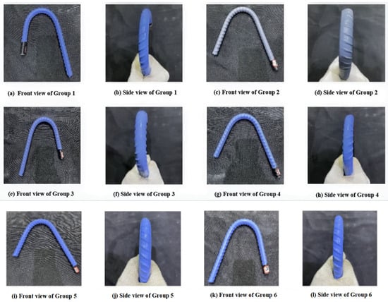
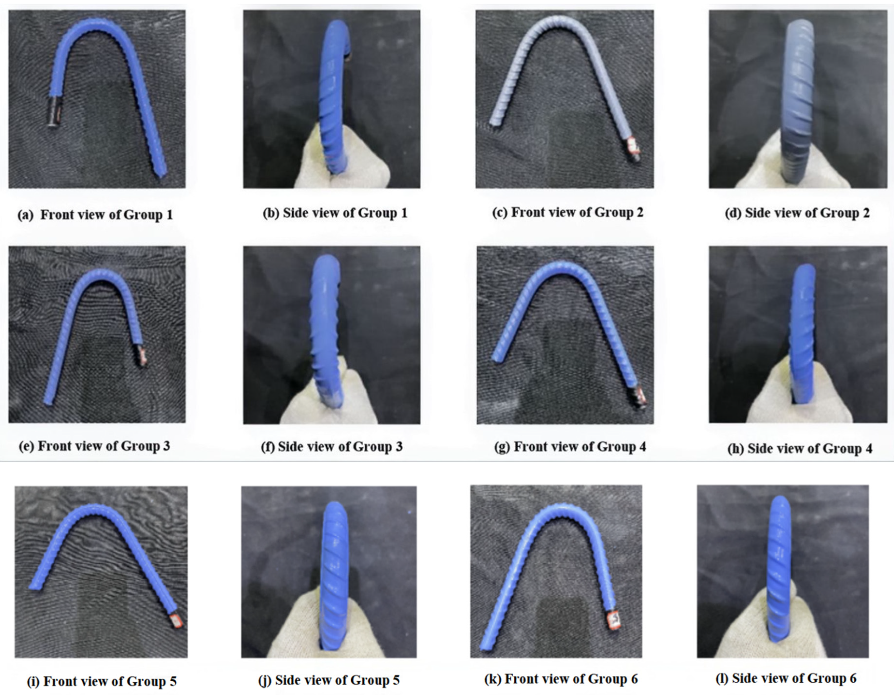
The front and side views of the epoxy-coated reinforcing bars following a 180° cold bending test are shown in Figure 15. None of the six samples of water-based epoxy-coated reinforcing bars exhibited any visible cracks or delamination on their surfaces after bending, indicating that this coating system possesses excellent toughness and good workability.
Figure 15.
Surface of coated reinforcing bars after cold bending.
3.5. Test Results on the Deformation Coordination Between Coated Reinforcing Bars and Their Coatings
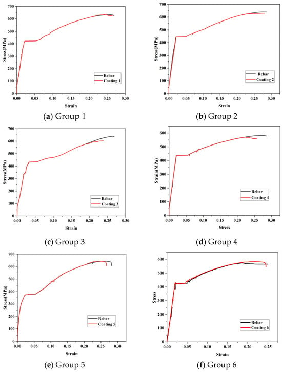
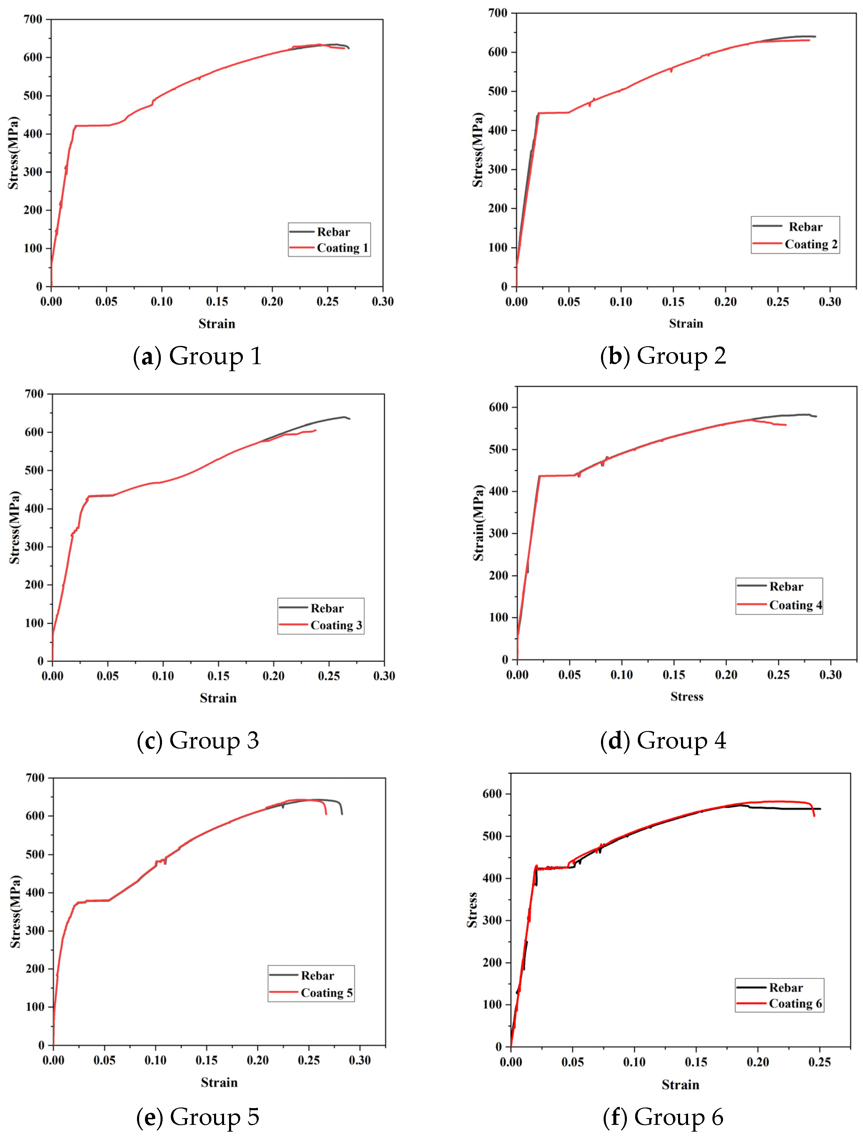
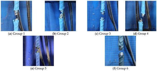
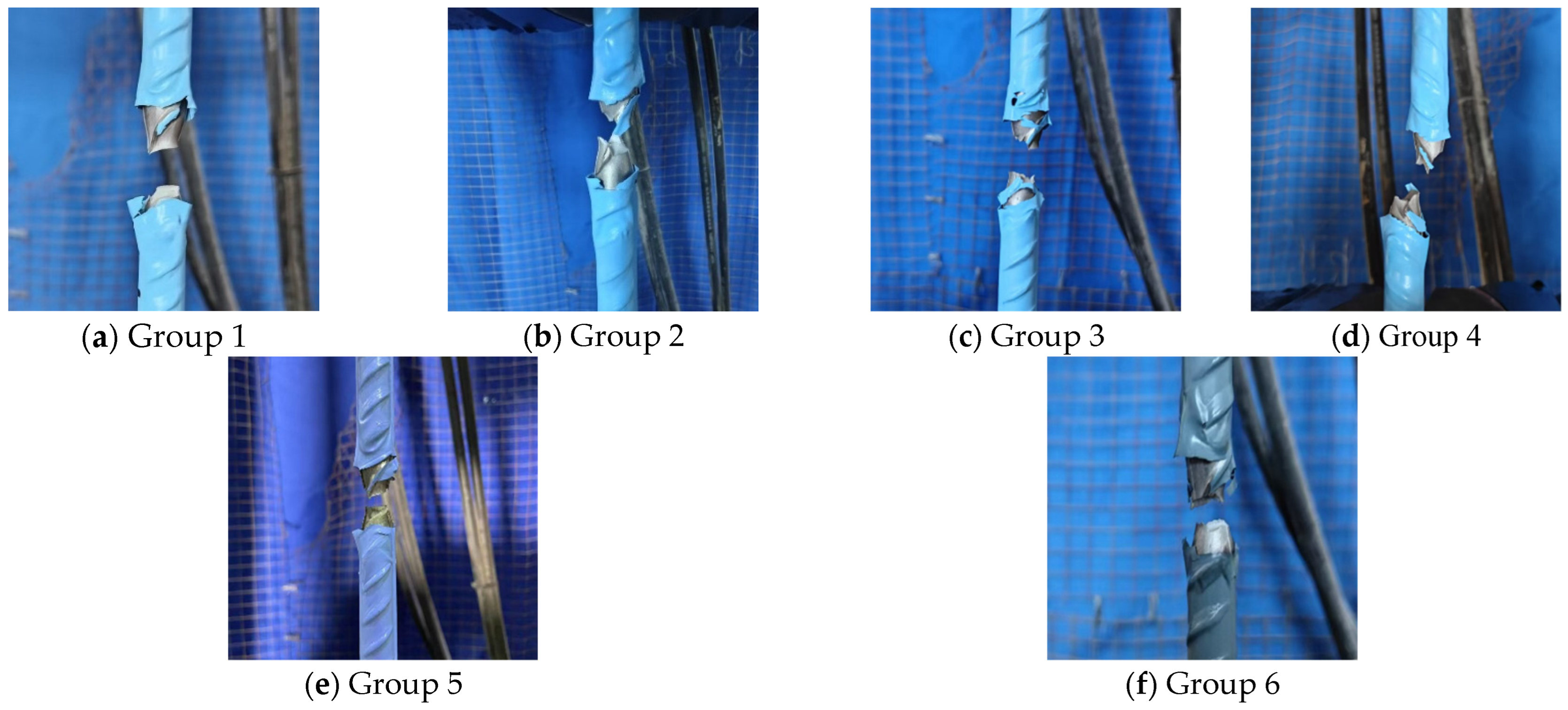
The results of tensile tests on coated reinforcing bars based on strain measurements are shown in Table 7 and Figure 16. The deformation coordination capability of the self-made water-based coated reinforcing bars was significantly superior to that of commercially available coatings overall. Among these, the coating containing 0.3% PAG exhibited the best deformation coordination; strain mismatch between the reinforcing bar and the coating did not occur until the elongation reached 23.67%, and the coating only failed at the point of bar fracture (as shown in Figure 17), with no cracks or delamination observed elsewhere. This indicates that toughening via nanocomposites can effectively delay the onset of strain mismatch. In the coating containing 1% amino silane coupling agent (Group 1), the improved interfacial adhesion delayed the onset of strain mismatch until an elongation of 21.65%, indicating that the coupling agent enhances the bonding performance. In the composite coating structure, whilst an amino coupling agent was used in the primer, the introduction of different fillers in the intermediate and top coats yielded varying coordination effects: when 10% zinc phosphate was introduced into both the intermediate and top coats, the elongation at which strain mismatch occurred was relatively low; when the intermediate coat remained as 10% zinc phosphate but the top coat was replaced with fly ash microspheres (Group 4), the strain mismatch phenomenon was delayed until an elongation of 22.62%, indicating that the fly ash microspheres exerted a toughening effect; and when polystyrene microspheres were used in the top coat (Group 5), the elongation at the onset of strain mismatch was slightly lower than that of Group 4. It is worth noting that Group 6, with a top coat of quartz powder, exhibited the lowest elongation at the onset of deformation mismatch, at only 18.26%, further confirming that the introduction of excessive rigid fillers weakens the coating’s deformation coordination capability.
Table 7.
Experimental results on the coordination between coating and reinforcement deformation.
Figure 16.
Tensile stress–strain curve for coated reinforcing bars.
Figure 17.
Fracture morphology of coated reinforcing bars under tensile loading.
3.6. Speckle Test Results for Coated Reinforcing Bars
Table 8 presents the speckle test results for the coated reinforcing bars. The results indicate that the maximum longitudinal displacement at crack initiation for the coated reinforcing bars in Group 2, to which 0.3% PAG was added, was 10.85%. Compared with the steel bars in Group 2, which contained 0.3% PAG, the toughness of the coated steel bars in Group 3—where both the intermediate and top coats contained 10% Zn3(PO4)2—decreased slightly, with a longitudinal displacement of 8.633% at crack initiation. However, after replacing the top coat with fly ash microspheres (Group 4), the toughening effect was significant, with the longitudinal displacement at crack initiation increasing to 10.33%. This suggests that the microspheres may force the crack to detour or bifurcate, thereby lengthening the propagation path, dissipating more energy, and delaying crack propagation.
Table 8.
Speckle experiment results.
Based on the preliminary experimental investigations and related research findings from earlier studies in this research programme concerning the toughening of epoxy coatings using fly ash microspheres and polystyrene microspheres, the toughening effect of fly ash microspheres can be attributed to the crack deflection and bifurcation effects they induce within the stress field. According to Clause 2.4.8 of GB/T 3961—2018 [37], crack deflection refers to the phenomenon whereby the direction of crack propagation changes; it is a common microstructural mechanical behaviour observed in particulate or second-phase toughening materials. When microspheres are uniformly dispersed within the epoxy matrix, the difference in elastic modulus between the microspheres and the matrix creates a local stress disturbance field near the crack tip, forcing the crack to bypass the microsphere/matrix interface, thereby extending the crack propagation path and dissipating more fracture energy. Polystyrene microspheres, on the other hand, primarily rely on their strong interfacial bonding with the epoxy matrix; they absorb strain energy through their own elastic deformation, thereby delaying crack initiation. The aforementioned mechanisms have been reported in the relevant literature [38,39].
4. Conclusions
In this study, a non-ionic water-based epoxy curing agent was prepared using aliphatic polyamines and E20 epoxy resin as the main raw materials. This was then blended with a water-based polyurethane-toughened epoxy emulsion and inorganic fillers to produce a water-based epoxy coating. The curing agent ratio was adjusted and the curing process optimised by testing the tensile properties of the water-based epoxy coating film. After applying a layer of water-based epoxy coating to the surface of steel reinforcement bars and their electrodes, electrochemical testing, coating thickness measurement, and coating continuity testing were employed to investigate the effects of filler type, particle size, and content on coating performance. Furthermore, the mechanical properties and deformation coordination of epoxy-coated steel reinforcement were evaluated through cold bending tests, tensile tests based on strain measurement, and tensile tests based on the speckle correlation method. The main conclusions are as follows:
(1) Using a polyurethane-toughened water-based epoxy emulsion as the base, as well as a curing agent comprising aliphatic polyamine TEPA and epoxy resin E20 in a molar ratio of 2.0:1, under process conditions of 45% solids content and curing at 60 °C for 6 h, the resulting coating film achieved a tensile strength of 40.11 MPa, with an elongation at break of 19.94%. This demonstrates a high degree of deformability whilst ensuring sufficient strength, achieving a good balance between rigidity and toughness.
(2) Electrochemical testing indicated that the introduction of 1% silane coupling agent caused the corrosion current density to drop sharply from 0.121 μA/cm2 to 0.00982 μA/cm2 after 60 days of immersion in a 3.5% NaCl solution, with a significant enhancement in interfacial adhesion. When 10% zinc phosphate was blended on top of the silane-modified coating, the corrosion current density was further reduced to 0.00589 μA/cm2, with a protective effect comparable to that of a coating containing 0.3% graphene/polyaniline (PAG) nanocomposite (0.00538 μA/cm2).
(3) The water-based epoxy coating containing 10% zinc phosphate formed a continuous dense film with no visible ‘rib gaps’ or through-penetrating micropores, and an average single-layer thickness of approximately 84 µm. Following a 180° cold bending test, no cracks or delamination were observed on the surface of any of the water-based epoxy-coated reinforcing bars, demonstrating excellent workability and adhesive toughness.
(4) Deformation coordination and digital speckle tests confirmed that the in-house water-based epoxy coating system significantly improved deformation tracking capability. The coating containing 0.3% PAG exhibited an initial strain at the start of cracking of 23.67%, with a longitudinal strain at the crack tip of 10.85%. When using a multi-layer system comprising ‘silane primer–10% zinc phosphate intermediate coat–fly ash microsphere top coat’, the initial strain at the start of cracking was 22.62%, with a longitudinal strain at the crack tip of 10.33%. This indicates that fly ash microspheres can effectively toughen the coating and inhibit crack propagation, achieving good deformation coordination between the coating and the reinforcing steel without significantly compromising corrosion resistance.
The core physical mechanism of this study lies in controlling the cross-linking density of the coating film within the ‘critical chain length’ range by adjusting the curing agent molar ratio and the curing process, thereby achieving a balance between stiffness and toughness. Furthermore, by leveraging the dual combined effects of silane’s interfacial chemical bonding and zinc phosphate’s physical barrier and passivation film formation, highly effective corrosion protection is achieved. Finally, by utilising the difference in elastic modulus between fly ash microspheres and the substrate to induce crack deflection, the deformation compatibility of the coated reinforcing bars is significantly enhanced. It should be noted that this study did not conduct a systematic cost analysis of raw materials nor carry out exposure tests in a real marine environment. In future research, we will conduct a comprehensive economic analysis and undertake long-term wet–dry cycling simulation tests and in situ panel tests.
Author Contributions
Conceptualisation, Z.H.; methodology, Z.H. and Y.X.; software, Y.X.; validation, L.M.; formal analysis, C.Z.; investigation, Z.H.; resources, Z.H.; data curation, L.M.; writing—original draft preparation, Z.H.; writing—review and editing, L.M.; supervision, Z.H. and Y.X.; visualisation, Y.X.; project administration, C.Z.; funding acquisition, C.Z. All authors have read and agreed to the published version of the manuscript.
Funding
This research was supported by the Dezhou Key Laboratory of Prefabricated Buildings and Intelligent Construction (PT2025KJT001).
Data Availability Statement
The original contributions presented in this study are included in the article. Further inquiries can be directed to the corresponding author.
Conflicts of Interest
The authors declare no conflicts of interest.
References
- Zhang, M.H.; Li, Z.Y.; Cui, J.Y.; Xu, R.H. Study on Cl− Erosion of Concrete under the Combined Effect of Fatigue Load and Wet-Dry Cycles: A Review. Appl. Sci. 2023, 13, 6691. [Google Scholar] [CrossRef] [Scilit]
- Manning, D.G. Corrosion performance of epoxy-coated reinforcing steel: North American experience. Constr. Build. Mater. 1996, 10, 349–365. [Google Scholar] [CrossRef] [Scilit]
- Pincheira, J.A.; Aramayo, A.; Fratta, D.; Kim, K.S. Corrosion Performance of Epoxy-Coated Bars in Four Bridge Decks Subjected to Deicing Salts: 30-Year Perspective. J. Perform. Constr. Facil. 2015, 29, 04014097. [Google Scholar] [CrossRef] [Scilit]
- Sharma, N.; Sharma, S.; Sharma, S.K.; Mahajan, R.L.; Mehta, R. Evaluation of corrosion inhibition capability of graphene modified epoxy coatings on reinforcing bars in concrete. Constr. Build. Mater. 2022, 322, 126495. [Google Scholar] [CrossRef] [Scilit]
- Islam, G.M.; Ahmed, E.; Hossain, M.; Uddin, S. Bond Strength of Fusion Bonded Epoxy-Coated Reinforcement in Concrete. J. Civ. Eng. Forum 2019, 5, 255. [Google Scholar] [CrossRef] [Scilit]
- Pei, L.C.; Lin, D.; Yuan, S.C.; Lu, R.J.; Bai, Z.H.; Sun, Y.; Zhu, Y.J.; Jiang, Y.X.; Zhu, J.J. A multifunctional and long-term waterborne anti-corrosion coating with excellent? hexagonal warrior? properties. Chem. Eng. J. 2023, 457, 141158. [Google Scholar] [CrossRef] [Scilit]
- He, T.; Yuan, Q.; Li, H.J.; Xie, P.; Li, C.H.; He, Y.; Lin, Y.H. Waterborne epoxy coating with excellent barrier and self-healing properties for long-term corrosion protection. Int. J. Electrochem. Sci. 2024, 19, 100486. [Google Scholar] [CrossRef] [Scilit]
- Zhang, K.; Huang, J.R.; Wang, Y.G.; Li, W.B.; Nie, X.A. Eco-Friendly Epoxy-Terminated Polyurethane-Modified Epoxy Resin with Efficient Enhancement in Toughness. Polymers 2023, 15, 2803. [Google Scholar] [CrossRef] [Scilit] [PubMed]
- Shen, B.H.; Sheng, Y.P.; Abdulakeem, A.; Zhu, C.Y.; Yang, H.F.; Wang, L.B. An experimental characterization of the properties of graphene oxide-Waterborne epoxy resin coating of concrete after chloride erosion. Constr. Build. Mater. 2024, 428, 136207. [Google Scholar] [CrossRef] [Scilit]
- Guan, H.Y.; Zhang, D.Y.; Liu, Z.Y.; Ding, Y.; Liu, Q.B. Toughening and corrosion resistance enhancement of waterborne epoxy films via polyurethane-based reactive epoxy emulsifier and capping agents. J. Mater. Sci. 2025, 60, 20110–20125. [Google Scholar] [CrossRef] [Scilit]
- Wen, Y.; Liu, X.D.; Liu, L. Improving Epoxy Resin Performance Using PPG and MDI by One-Step Modification. Processes 2022, 10, 929. [Google Scholar] [CrossRef] [Scilit]
- Truc, T.A.; Hoan, N.X.; Bach, D.T.; Thuy, T.T.; Ramadass, K.; Sathish, C.I.; Chinh, N.T.; Trinh, N.D.; Hoang, T. Hydrothermal Synthesis of Cobalt Doped Magnetite Nanoparticles for Corrosion Protection of Epoxy Coated Reinforced Steel. J. Nanosci. Nanotechnol. 2020, 20, 3519–3526. [Google Scholar] [CrossRef] [Scilit] [PubMed]
- Li, Z.Y.; Wang, Y.; Cao, J.C.; Meng, X.H.; Aamir, R.M.; Lu, W.B.; Suo, T. Effects of loading rates on mode I interlaminar fracture toughness of carbon/epoxy composite toughened by carbon nanotube films. Compos. Part B Eng. 2020, 200, 108270. [Google Scholar] [CrossRef] [Scilit]
- Wazalwar, R.; Tripathi, N.; Raichur, A.M. Mechanical and curing behavior of epoxy composites reinforced with polystyrene-graphene oxide (PS-GO) core-shell particles. Compos. Part C Open Access 2021, 5, 100128. [Google Scholar] [CrossRef] [Scilit]
- Park, Y.T.; Qian, Y.Q.; Chan, C.; Suh, T.; Nejhad, M.G.; Macosko, C.W.; Stein, A. Epoxy Toughening with Low Graphene Loading. Adv. Funct. Mater. 2015, 25, 575–585. [Google Scholar]
- Chen, C.G.; Justice, R.S.; Schaefer, D.W.; Baur, J.W. Highly dispersed nanosilica-epoxy resins with enhanced mechanical properties. Polymer 2008, 49, 3805–3815. [Google Scholar] [CrossRef] [Scilit]
- Jin, R.; Xu, B.; Guo, D.; Shi, B.; Chen, Y.; Jia, X.; Qu, L. Advanced chemical modification technology of inorganic oxide nanoparticles in epoxy resin and mechanical properties of epoxy resin nanocomposites: A review. Nano Mater. Sci. 2025, 7, 643–664. [Google Scholar] [CrossRef] [Scilit]
- Ai, J.; Cheng, W.; Wang, P.; Qian, W.; Chen, Q.H. Silica solid particles toughening, strengthening and anti-aging on epoxy resin. J. Appl. Polym. Sci. 2021, 138, 50331. [Google Scholar]
- Su, Y.; Qiu, S.; Wei, J.; Zhu, X.; Zhao, H.; Xue, Q. Sulfonated polyaniline assisted hierarchical assembly of graphene-LDH nanohybrid for enhanced anticorrosion performance of waterborne epoxy coatings. Chem. Eng. J. 2021, 426, 131269. [Google Scholar] [CrossRef] [Scilit]
- Cai, H.; Li, X.; Zhang, Y.; Yang, C.; Cui, S.; Sheng, L.; Xu, D.; Fu, R.K.; Tian, X.; Chu, P.K.; et al. A high corrosion-resistant waterborne epoxy resin coating improved by addition of multi-interface structured zinc phosphate particles. J. Mater. Res. Technol. 2023, 26, 7829–7844. [Google Scholar] [CrossRef] [Scilit]
- Tang, F.; Bai, J.; Yi, T.-H.; Li, H.-N. Monitoring the propagation of coating damage in epoxy-coated steel rebar using no-core fiber optic sensors with strain compensation. J. Mater. Civ. Eng. 2026, 38, 04025504. [Google Scholar] [CrossRef] [Scilit]
- GB/T 1040.3-2006; Plastics—Determination of Tensile Properties—Part 3: Test Conditions for Films and Sheets. China Standard Press: Beijing, China, 2006.
- Wang, H.; Zhang, M.; Huo, S.X.; Huang, J.; Leng, F.G. Interpretation of T/CECS 874-2021 “Technical specification for application of steel corrosion inhibitor”. Eng. Qual. 2023, 41, 74–78. [Google Scholar]
- ASTM G59-23; Standard Test Method for Conducting Potentiodynamic Polarization Resistance Measurements. ASTM International: West Conshohocken, PA, USA, 2023.
- GB/T 25826-2022; Epoxy-Coated Steel for the Reinforcement of Concrete. China Standard Press: Beijing, China, 2022.
- GB/T 28900-2022; Test Methods of Steel for Reinforcement of Concrete. China Standard Press: Beijing, China, 2022.
- Zhao, R.; Sun, Y.; Yu, G.; Sun, P.; Huang, Y.; Zhang, Y.; Jia, J. Correlation-Based Out-of-Plane Displacement Measurement for Optical Fiber Material. Photonics 2021, 8, 348. [Google Scholar] [CrossRef] [Scilit]
- Liu, R.; Xie, X.; Wang, Q.; Zhang, L.; Yan, X. Fabrication of microscale heat-resistant and customizable speckles for deformation measurement using digital image correlation. Opt. Laser Technol. 2025, 192, 113814. [Google Scholar] [CrossRef] [Scilit]
- Pan, B. Digital image correlation for surface deformation measurement: Historical developments, recent advances and future goals. Meas. Sci. Technol. 2018, 29, 082001. [Google Scholar] [CrossRef] [Scilit]
- Blaber, J.; Adair, B.; Antoniou, A. Ncorr: Open-Source 2D Digital Image Correlation Matlab Software. Exp. Mech. 2015, 55, 1105–1122. [Google Scholar] [CrossRef] [Scilit]
- Darko, C. The link between swelling ratios and physical properties of EPDM rubber compound having different oil amounts. J. Polym. Res. 2022, 29, 325. [Google Scholar] [CrossRef] [Scilit]
- Djenaoucine, L.; Argiz, C.; Picazo, Á.; Moragues, A.; Gálvez, J. The corrosion-inhibitory influence of graphene oxide on steel reinforcement embedded in concrete exposed to a 3.5M NaCl solution. Cem. Concr. Compos. 2025, 155, 105835. [Google Scholar]
- Caldona, E.B.; Smith, D.W.; Wipf, D.O. Surface electroanalytical approaches to organic polymeric coatings. Polym. Int. 2021, 70, 927–937. [Google Scholar]
- Tang, F.J.; Cui, H.; Li, B.; Lin, W.W. Corrosion Resistance of Plain and Ribbed Steel Bars Coated with Quartz Sand-Modified Enamel in Simulated Concrete Pore Solutions. J. Mater. Eng. Perform. 2026, 35, 5100–5117. [Google Scholar]
- Moolla, A.; Jarratt, N.; Beushausen, H. Investigating the effects of anti-corrosive coatings on the bond between corrosion-damaged rebar and concrete repair materials. MATEC Web Conf. 2022, 364, 04007. [Google Scholar] [CrossRef] [Scilit]
- Liu, Y.; Bian, D.; Zhao, Y. The long-term effectiveness and failure mechanism of the chemically bonded phosphate ceramic coatings with different thickness. Int. J. Appl. Ceram. Technol. 2019, 16, 1684–1695. [Google Scholar] [CrossRef] [Scilit]
- GB/T 3961-2009; Terms for Fibre Reinforced Plastics. China Standard Press: Beijing, China, 2009.
- Li, C.X.; Chen, Z.Y.; Liu, Y. Study of mechanical properties of micron polystyrene-toughened epoxy resin. Appl. Sci. 2023, 13, 3981. [Google Scholar] [CrossRef] [Scilit]
- Garcia, C.D.; Shahapurkar, K.; Doddamani, M.; Kumar, G.M.; Prabhakar, P. Effect of arctic environment on flexural behavior of fly ash cenosphere reinforced epoxy syntactic foams. Compos. Part B Eng. 2018, 151, 265–273. [Google Scholar] [CrossRef] [Scilit]

Disclaimer/Publisher’s Note: The statements, opinions and data contained in all publications are solely those of the individual author(s) and contributor(s) and not of MDPI and/or the editor(s). MDPI and/or the editor(s) disclaim responsibility for any injury to people or property resulting from any ideas, methods, instructions or products referred to in the content. |
© 2026 by the authors. Licensee MDPI, Basel, Switzerland. This article is an open access article distributed under the terms and conditions of the Creative Commons Attribution (CC BY) license.