


Abstract
Graphene nanoplatelets (GNPs)-reinforced AlSi10Mg composites were fabricated by selective laser melting (SLM), and their corrosion resistance was systematically investigated as a function of GNPs content (0, 0.1, 0.3, and 0.5 wt.%) and corrosion duration. In the short term (≤30 days), the corrosion resistance followed the order: 0.1 wt.% GNPs/AlSi10Mg > 0.3 wt.% GNPs/AlSi10Mg > 0.5 wt.% GNPs/AlSi10Mg > AlSi10Mg. The 0.1 wt.% composite exhibited the best performance, attributed to the uniform dispersion of GNPs that filled micropores and microcracks to form a physical barrier against corrosive ions, along with favorable interfacial bonding that hindered crack growth and reduced corrosion pathways. After 60 days of exposure, however, the ranking reversed to: AlSi10Mg > 0.1 wt.% GNPs/AlSi10Mg > 0.3 wt.% GNPs/AlSi10Mg > 0.5 wt.% GNPs/AlSi10Mg. EIS analysis revealed a porous electrode behavior in the low-frequency response, captured by the constant phase element in the equivalent circuit. The long-term deterioration arose from the gradual penetration of corrosive media through micropores and microcracks, which triggered galvanic corrosion between GNPs and the matrix and rendered the barrier effect ineffective. These findings demonstrate that GNPs addition increases both the number and the total area of cathodic sites in the matrix alloy, thereby accelerating corrosion under prolonged exposure. In essence, GNPs serve as a protective barrier in the short term but transition to corrosion accelerators under long-term exposure.
1. Introduction
AlSi10Mg alloy is widely employed in the automotive, aerospace, and marine industries owing to its favorable combination of properties. However, its relatively low strength, inadequate hardness, and poor wear resistance, have restricted its application under more demanding service conditions. Consequently, the development of advanced aluminum matrix composites has become a critical direction and a significant challenge for the design and fabrication of high-performance structural components [1]. This challenge is particularly acute when considering that exposure to corrosive environments can significantly accelerate crack initiation and lead to premature structural failure, making corrosion a critical concern for aluminum alloys used in marine applications or in regions exposed to de-icing salts [2]. Accordingly, the production of aluminum matrix composites with excellent mechanical properties and corrosion resistance has attracted considerable attention from both academia and industry.
In recent years, graphene has emerged as one of the most promising reinforcements for metal matrix composites, driven by its outstanding mechanical properties [3,4,5,6,7,8]. Nevertheless, the large specific surface area of graphene, together with the substantial density mismatch and poor wettability between graphene and metallic matrices, makes homogeneous dispersion extremely difficult, often leading to severe agglomeration. Conventional manufacturing processes have yet to yield satisfactory results at an industrial scale. Selective laser melting (SLM) overcomes the limitations of traditional methods in forming complex integrated components. It offers advantages including shortened production cycles, reduced costs, and precise process control. Moreover, SLM allows flexible tuning of the microstructure and mechanical properties, as well as the direct fabrication of near-net-shaped parts. On the other hand, chemical modification of graphene surfaces suffers from complex procedures, incomplete coating coverage, and the risk of introducing impurities, which impede large-scale application [9]. In contrast, conventional ball milling offers a simple, highly efficient, and environmentally friendly route for preparing graphene-reinforced composite powders. Therefore, the combination of ball milling with SLM technology holds great promise for the fabrication of GNPs/AlSi10Mg composites. SLM enables the production of components with complex geometries and tailored material distributions that cannot be achieved by traditional methods, offering added value for high-end engineering applications.
To evaluate the corrosion performance of the composites, the 3.5 wt.% NaCl solution was selected as the corrosive medium, as it closely simulates the chloride concentration of natural seawater and represents a typical aggressive environment for aluminum alloys [10]. GNPs are impermeable to gases and water and are chemically inert toward most substances [11,12,13,14], making them promising candidates for anti-corrosion and anti-oxidation coatings as well as metal matrix composites. Studies have shown that GNPs can reduce corrosion rates and suppress hydrogen evolution, positioning them as effective protective barriers [15,16,17]. Li et al. [2] fabricated graphene-reinforced nickel matrix composites via SLM and attributed the enhanced corrosion resistance primarily to the large specific surface area of graphene. In contrast, Schriver and Rashad [18,19] reported that although graphene coatings on copper and silicon substrates provided effective short-term oxidation protection, the graphene-reinforced composites suffered from more severe corrosion than bare copper surfaces under long-term exposure. These contradictory findings indicate that the anti-corrosion performance of graphene-reinforced metal matrix composites remains inconclusive, and the underlying mechanisms are still debated. Therefore, a systematic investigation into the effect of GNPs on the corrosion resistance and the underlying corrosion mechanisms of SLM-fabricated GNPs/AlSi10Mg composites is of significant academic importance. However, studies on this topic remain scarce to date. Our previous work [20] revealed that the silicon phase morphology significantly influences the corrosion resistance of SLM-fabricated AlSi10Mg alloy. Extending this investigation to GNPs/AlSi10Mg composites, the present work systematically examines the time-dependent corrosion performance over an extended period of up to 60 days, in contrast to previous studies that have predominantly focused on short-term behavior (typically <48 h). A key novelty lies in the identification of a complete reversal in corrosion resistance after prolonged exposure, and the elucidation of the underlying transition mechanism from a protective barrier to a galvanic corrosion accelerator.
Accordingly, the primary objective of this work is to systematically investigate the influence of varying GNPs additions (0, 0.1, 0.3, and 0.5 wt.%) and corrosion duration on the corrosion performance of SLM-fabricated AlSi10Mg composites, with the aim of elucidating the relationship between these variables and the resulting corrosion resistance, and revealing the corrosion mechanisms governing these GNPs-reinforced AlSi10Mg composites.
2. Materials and Methods
AlSi10Mg alloy powder (supplied by Renishaw Plc., Gloucestershire, UK) was used as the starting material, and its chemical composition is listed in Table 1. Graphene nanoplatelets (GNPs) were purchased from Tangshan Jianhua Technology Development Co., Ltd., Tangshan, China. The GNPs contents of 0.1, 0.3, and 0.5 wt.% were selected based on literature precedent and preliminary experiments. This range covers the transition from effective reinforcement (0.1 wt.%) to agglomeration-dominated behavior with pronounced porosity (0.5 wt.%), with 0.3 wt.% as an intermediate composition [19]. The GNPs and AlSi10Mg powders were mixed by planetary ball milling under vacuum atmosphere with a ball-to-powder weight ratio of 8:1. The milling was conducted in an intermittent mode: 20 min of milling followed by 10 min of rest, with a total effective milling time of 2 h. The GNPs/AlSi10Mg composites were fabricated using a Renishaw AM250 selective laser melting (SLM) system (Renishaw Plc., Gloucestershire, UK), with the processing parameters summarized in Table 2. Prior to fabrication, the build platform was preheated to 200 ± 5 °C. To achieve optimal forming quality, a laser scanning strategy with a 67° rotation angle between adjacent layers was adopted. Before the SLM process, the powder mixture was dried in a vacuum oven (XMTD-8222, Shanghai Jinghong Experimental Equipment Co., Ltd., Shanghai, China) at 100 ± 2 °C for 2 h. High-purity argon was introduced as a protective atmosphere throughout the process to prevent oxidation of the specimens during fabrication. The fabricated specimens had dimensions of 10 ± 0.1 mm × 10 ± 0.1 mm × 10 ± 0.1 mm (measured by digital caliper with ± 0.01 mm precision).
Table 1.
Chemical composition of the AlSi10Mg powder (wt.%).
Table 2.
Parameters of SLM process.
Metallographic observation was conducted using an optical microscope (OM, Carl Zeiss Microscopy GmbH, Jena, Germany). Ten optical microscopy images were randomly captured at different locations for each specimen under the same magnification. The images were then processed and analyzed using ImageJ software (Version 1.53c), and the relative density of each specimen was determined from the average of ten measurements. The microstructure and elemental composition were characterized using a scanning electron microscope (SEM, Zeiss Ultra 55, Carl Zeiss Microscopy GmbH, Jena, Germany) equipped with energy-dispersive spectroscopy (EDS, Zeiss Ultra 55, Carl Zeiss Microscopy GmbH, Jena, Germany). The metallographic etchant used was Keller’s reagent (2.5 vol% HNO3 + 1 vol% HF + 95 vol% H2O + 1.5 vol% HCl), and the etching time was 15 s.
Specimens for corrosion testing were machined to dimensions of 10 ± 0.1 mm × 10 ± 0.1 mm × 3 ± 0.05 mm. The surface exposed to the corrosive solution was the XZ-plane. Prior to testing, the specimens were successively ground with SiC abrasive papers from 400# to 2000#, followed by ultrasonic cleaning and drying. Copper wires were then soldered to the specimens, which were then sealed with epoxy resin, leaving an exposed working area of 1 ± 0.01 cm2. After the epoxy resin had fully cured, the exposed surfaces were reground, polished, ultrasonically cleaned, and dried again prior to testing.
Mass loss measurements were conducted by suspending specimens with varying GNPs contents in 3.5 wt.% NaCl solution. For each time point, a separate set of independent specimens was used. At predetermined time intervals, the specimens were removed and their surface and cross-sectional morphologies were examined. After removal, the specimens were rinsed with deionized water and brushed with a stiff brush to remove loose corrosion products. They were then immersed in HNO3-based descaling solution to remove residual corrosion products until complete removal was achieved at room temperature. The specimens were subsequently rinsed with deionized water, cleaned ultrasonically in ethanol, dried for 24 h, and weighed using a balance with an accuracy of ± 0.1 mg to determine the mass loss. Three parallel specimens were tested for each condition, and the average value was reported.
Electrochemical impedance spectroscopy (EIS) measurements were performed at room temperature using a CHI660E electrochemical workstation (Shanghai Chenhua Instrument Co., Ltd., Shanghai, China) (potential resolution: 1 mV; current resolution: 0.1 pA). A conventional three-electrode cell configuration was employed, consisting of a platinum sheet as the counter electrode (10 ± 0.01 mm × 10 ± 0.01 mm × 0.5 ± 0.01 mm), a saturated calomel electrode (SCE) as the reference electrode, and the test alloy as the working electrode. The electrolyte was 3.5 wt.% NaCl solution (0.56 M) prepared from deionized water. EIS measurements were carried out over a frequency range from 100 kHz to 10 mHz with an AC perturbation amplitude of 10 ± 0.1 mV (RMS). Prior to EIS testing, all specimens were immersed in NaCl solution for 30 min to attain a steady-state open-circuit potential (OCP). All EIS measurements were performed on three independently prepared specimens for each condition, with each specimen measured three times to verify the stability and reproducibility. The EIS data were analyzed and fitted to suitable equivalent circuits using ZSimpWin software (Version 3.60). The complex non-linear least squares (CNLS) simulations were carried out to determine the resulting impedance parameters quantitatively. The chi-squared (χ2) values were used to evaluate the goodness of fit between the experimental data and the simulated results, as previously reported [21,22,23,24]. All chi-squared values were below 1 × 10⁻³, indicating good fitting quality.
3. Results and Discussion
3.1. Microstructure Analysis
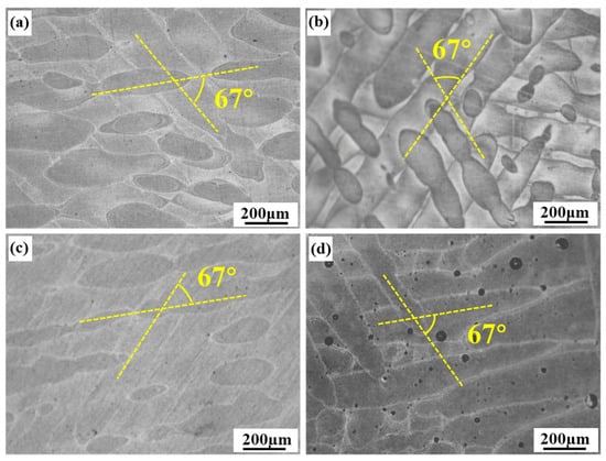
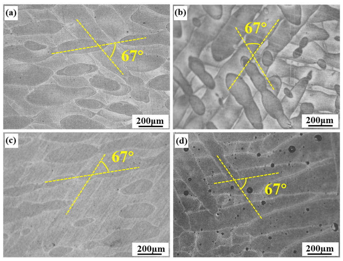
Figure 1 presents the cross-sectional metallographic microstructures of the SLM-fabricated AlSi10Mg alloy and GNPs/AlSi10Mg composites with varying GNPs contents (0.1 wt.%, 0.3 wt.%, and 0.5 wt.%). An interlayer angle of 67° is observed in all specimens, with the molten pools exhibiting elongated and ellipsoidal morphologies in an alternating overlapping arrangement. This morphological characteristic arises from the varying laser energy penetration during the SLM process. As shown in Figure 1a–c, no significant gas porosity is observed in the AlSi10Mg alloy or in the composites with 0.1 wt.% and 0.3 wt.% GNPs. However, when the GNPs content is increased to 0.5 wt.% (Figure 1d), pronounced porosity becomes evident. This can be attributed to two main factors. Firstly, during the SLM process, despite the protective argon atmosphere, the oxygen content within the build chamber can still reach 0.1–0.2%, forming oxide films on both the solidified and molten materials. As the laser agitates the melt pool, oxides on the top surface evaporate under laser irradiation, generating smoke-like oxide particles. Meanwhile, Marangoni convection tends to disrupt the oxide layer at the bottom of the melt pool, causing it to fuse into the underlying solidified layer. However, because the melt pool cannot adequately wet the surrounding material, the oxide films on the sidewalls remain intact, resulting in the formation of weak and porous regions [25]. Secondly, gas porosity also arises from gas entrapment, including pores originating from the raw powder material, pores caused by the evaporation of unstable constituents at the melt pool boundaries, and pores resulting from the expansion of entrapped gases. In addition, oscillations in shallow depressions induced by laser recoil pressure within the melt pool can also promote pore formation [26]. The progressive decrease in relative density with increasing GNPs content confirms this trend: the relative density values are 99.5% for the AlSi10Mg alloy, 99.1% for the 0.1 wt.% composite, 98.7% for the 0.3 wt.% composite, and 98.2% for the 0.5 wt.% composite, consistent with the microstructural observations.
Figure 1.
Metallurgical morphology of GNPs/AlSi10Mg composites with varying GNPs contents fabricated by SLM along XY plane: (a) AlSi10Mg alloy, (b) 0.1 wt.% GNPs/AlSi10Mg composite, (c) 0.3 wt.% GNPs/AlSi10Mg composite, (d) 0.5 wt.% GNPs/AlSi10Mg composite.
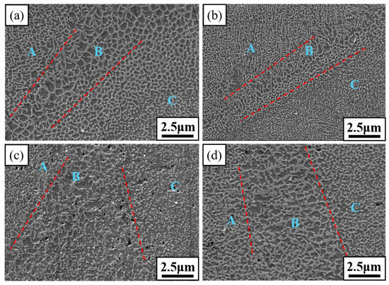
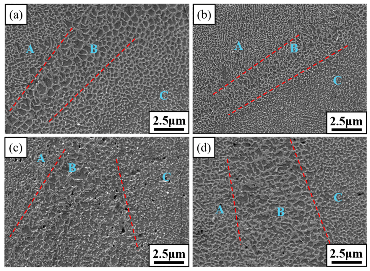
Figure 2 shows the cross-sectional microstructures of GNPs/AlSi10Mg composites with varying GNPs contents. The microstructures of all specimens consist of three distinct zones, including a fine-grained zone (marked “A”), a coarse-grained zone (marked “B”), and a heat-affected zone (marked “C”). The fine-grained zone exhibits a uniformly distributed cellular structure, in which the dark grey regions correspond to cellular Al solid solution, and the light grey network corresponds to eutectic silicon [27]. With increasing GNPs content, defects including gas porosity and lack of fusion become more pronounced, and the overall densification level of the specimens decreases accordingly. Notably, the cellular structure reaches its finest size at a GNPs content of 0.1 wt.%. Further increases in GNPs content lead to progressive coarsening of the cellular structure. This indicates that the addition of an appropriate amount of GNPs can achieve grain refinement. This is because uniformly dispersed GNPs provide a large number of nanoscale heterogeneous nucleation sites, while simultaneously exerting a pinning effect on grain boundary migration, thereby effectively inhibiting grain growth. However, when the GNPs content is excessively high, graphene agglomeration occurs, which weakens the refinement effect on the cellular structure. Consequently, the cellular structure size exhibits a trend of first decreasing and then increasing with increasing GNPs content. These findings are consistent with those reported by Yuan et al. [28].
Figure 2.
SEM images of GNPs/AlSi10Mg composites with varying GNPs contents fabricated by SLM along XY plane: (a) AlSi10Mg alloy, (b) 0.1 wt.% GNPs/AlSi10Mg composite, (c) 0.3 wt.% GNPs/AlSi10Mg composite, (d) 0.5 wt.% GNPs/AlSi10Mg composite.
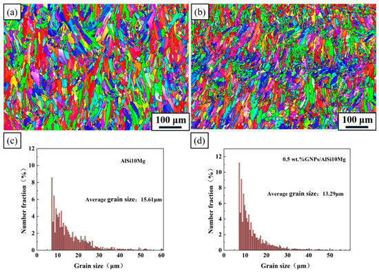
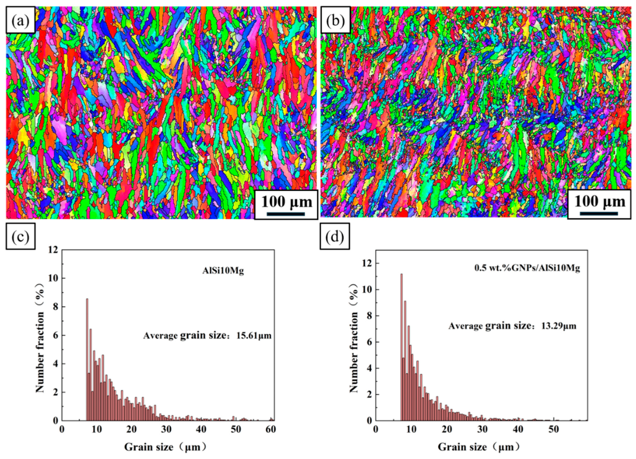
Figure 3 presents the EBSD inverse pole figure maps and grain size distributions of the longitudinal sections of the AlSi10Mg alloy and the 0.5 wt.% GNPs/AlSi10Mg composite. The microstructures of both specimens consist of overlapping melt pools. The interior of the melt pools is composed of columnar grains aligned along the building direction, whereas the melt pool boundaries are characterized by equiaxed grains. This microstructural feature arises from the “layer-by-layer, track-by-track” scanning strategy inherent to the SLM process, which induces remelting between adjacent scan tracks and between successive layers [29]. Figure 3c,d present the grain size distribution statistics for the two specimens. With the addition of GNPs, the average grain size decreases from 15.61 µm to 13.29 µm, indicating a significant grain refinement effect. This refinement arises from two factors. Firstly, GNPs act as heterogeneous nucleation substrates, substantially increasing the number of available nucleation sites. A sufficient density of nucleation sites effectively inhibits subsequent grain growth. Secondly, according to solidification theory, the temperature gradient (G) and growth rate (R) jointly determine the morphological characteristics of the solidification structure. The ratio G/R controls the solidification front morphology, while the product G × R represents the cooling rate, which governs the scale of the microstructure. The excellent thermal conductivity of graphene enhances the cooling rate of the composites, increases the G × R value, thereby yielding a finer grain structure. Within the melt pool, the temperature gradient G decreases progressively from the boundary toward the center, while the growth rate R increases in the same direction. Consequently, the G/R ratio decreases from the boundary to the center, leading to a transition in grain morphology from columnar to equiaxed. Meanwhile, the G × R value increases from the boundary toward the center, indicating a higher cooling rate, which results in greater undercooling. The maximum undercooling is achieved at the melt pool center, giving rise to the finest microstructure. In addition, the rapid solidification inherently suppresses grain growth. As a result, grains at the melt pool boundaries are coarser, whereas those in the interior of the melt pools are finer [30].
Figure 3.
EBSD inverse pole figure (IPF) maps and grain size distribution of specimens fabricated by SLM: (a,c) AlSi10Mg alloy, (b,d) 0.5 wt.% GNPs/AlSi10Mg composite.
3.2. Effect of Corrosion Duration on the Mass Loss Behavior of GNPs/AlSi10Mg Composites
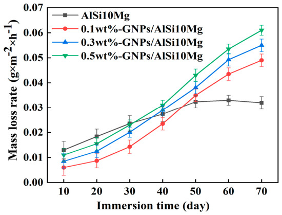
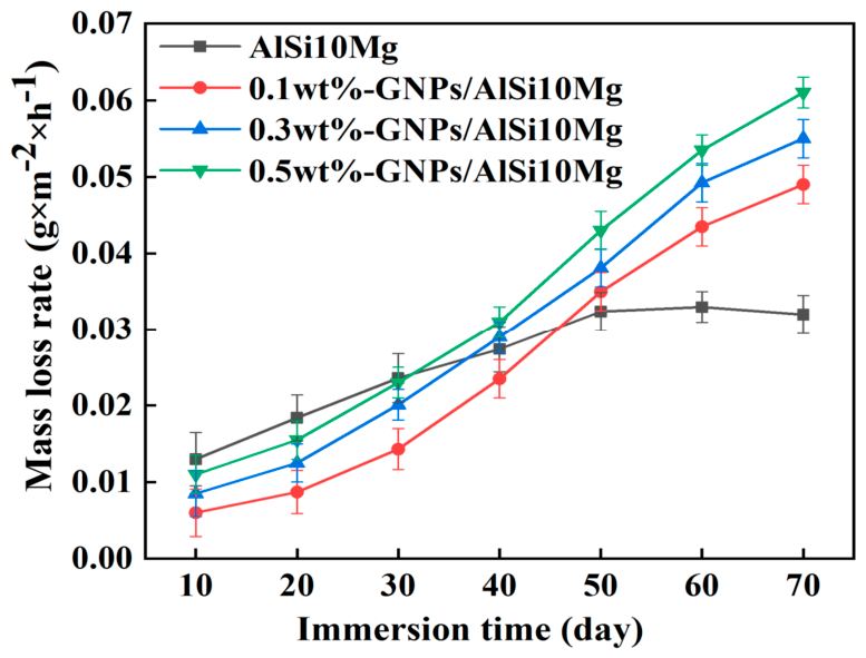
In this section, the corrosion behavior of GNPs/AlSi10Mg composites with varying GNPs contents is evaluated through mass loss measurements, followed by characterization of corrosion products and surface morphologies to elucidate the underlying mechanisms. Figure 4 presents the mass loss rate (g·m−2·h−1) as a function of immersion time for GNPs/AlSi10Mg composites with varying GNPs contents in 3.5 wt.% NaCl solution. The mass loss rate of all GNPs/AlSi10Mg composites exhibits a consistent increasing trend with prolonged immersion time, and a higher GNPs content corresponds to a higher mass loss rate. In contrast, the mass loss rate of the AlSi10Mg alloy first increases and then tends to stabilize. Notably, in the initial stage (≤30 days), all specimens exhibit relatively low mass loss rates, and the GNPs/AlSi10Mg composites show lower mass loss rates than the AlSi10Mg alloy (AlSi10Mg: 0.013 g·m−2·h−1; 0.1 wt.% GNPs/AlSi10Mg: 0.006 g·m−2·h−1; 0.3 wt.% GNPs/AlSi10Mg: 0.0085 g·m−2·h−1; 0.5 wt.% GNPs/AlSi10Mg: 0.011 g·m−2·h−1). This indicates that the composites possess superior corrosion resistance to the AlSi10Mg alloy at the early stage of corrosion, which is mainly attributed to the better protective performance of the oxide film formed in air compared with that formed in the solution. When the immersion time is extended to 30 days, the mass loss rate of the GNPs/AlSi10Mg composites remains lower than that of the AlSi10Mg alloy, as the addition of graphene renders the composite surface denser and smoother, effectively impeding the penetration of corrosive media. These findings are consistent with those reported by Wang et al. [31]. However, when the corrosion duration reaches 50 days, the mass loss rate of the AlSi10Mg alloy becomes lower than that of the 0.1 wt.% GNPs/AlSi10Mg composite, indicating a significant transition in the corrosion behavior. Subsequently, the mass loss rate of the AlSi10Mg alloy gradually stabilizes. Overall, the GNPs/AlSi10Mg composites exhibit an increasing corrosion rate under long-term exposure compared with the AlSi10Mg alloy, with higher GNPs content leading to more pronounced increase in corrosion rate and consequently poorer corrosion resistance. This agrees with the findings of Tunc et al. [32], suggesting that the addition of GNPs deteriorates the corrosion resistance of the composites after 50 days of corrosion exposure. This phenomenon suggests a mechanism in which the higher electrochemical potential of graphene relative to the aluminum matrix may induce galvanic corrosion in the presence of corrosive media, thereby accelerating the anodic dissolution of the aluminum matrix [33].
Figure 4.
The relationship between mass loss rate and immersion time of GNPs/AlSi10Mg composites with varying GNPs contents fabricated by SLM in the aerated 3.5 wt.% NaCl solution. Error bars represent standard deviations from triplicate measurements.
The transition from barrier-controlled to galvanic-corrosion-dominated behavior observed in the mass loss data (Figure 4) can be understood as a time-dependent process. In the initial stage (≤30 days), the dense oxide film and embedded GNPs effectively block electrolyte penetration. The corrosion rate is controlled by the barrier integrity. As immersion time progresses, however, the aggressive Cl− ions gradually penetrate through micro-defects. Once the electrolyte reaches the GNPs/matrix interface, the high electrical conductivity of GNPs establishes local galvanic cells where GNPs serve as cathodes and the adjacent Al matrix acts as the anode. This transition is not instantaneous but rather a gradual process, with the balance shifting from barrier protection to galvanic acceleration as the penetration depth increases. The 50-day transition point observed in the mass loss data (Figure 4) marks the crossover where galvanic effects begin to dominate over the barrier effect. It should be noted that intermediate surface characterization was not performed between 30 and 50 days to directly identify the onset of galvanic corrosion.
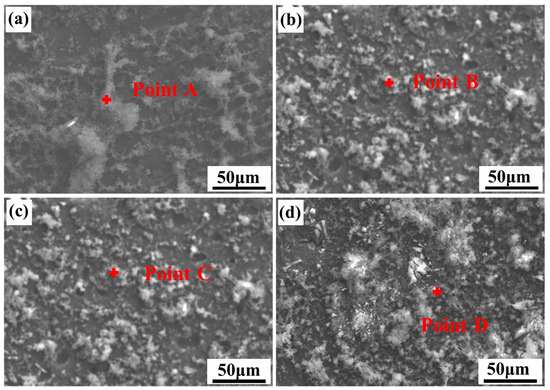
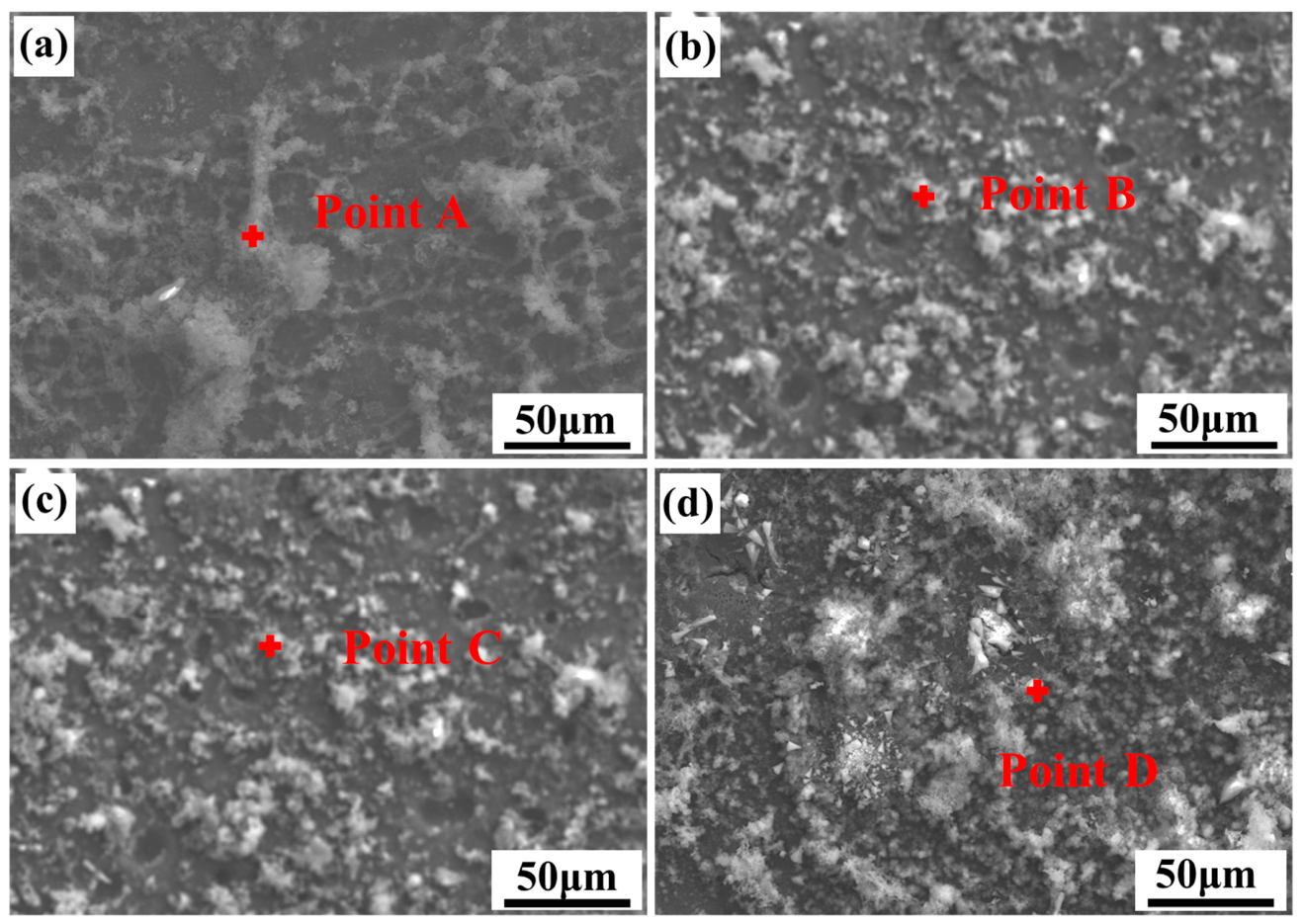
Figure 5 presents the surface morphologies of SLM-fabricated GNPs/AlSi10Mg composites with varying GNPs contents after 50 days of immersion in 3.5 wt.% NaCl solution. As shown in Figure 5a, the AlSi10Mg alloy surface is covered with unevenly distributed, loose light-gray corrosion products. At a GNPs content of 0.1 wt.% (Figure 5b), the corrosion products exhibit a fragmented morphology with varying particle sizes, uniformly distributed across the composite surface. When the GNPs content is increased to 0.3 wt.% and 0.5 wt.% (Figure 5c,d), the corrosion products begin to agglomerate into unevenly distributed blocky clusters, and the product layer exhibits visible pores and microcracks.
Figure 5.
The corrosion morphology of GNPs/AlSi10Mg composites with varying GNPs contents fabricated by SLM in the aerated 3.5 wt.% NaCl solution: (a) AlSi10Mg alloy, (b) 0.1 wt.% GNPs/AlSi10Mg composite, (c) 0.3 wt.% GNPs/AlSi10Mg composite, (d) 0.5 wt.% GNPs/AlSi10Mg composite.
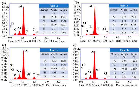
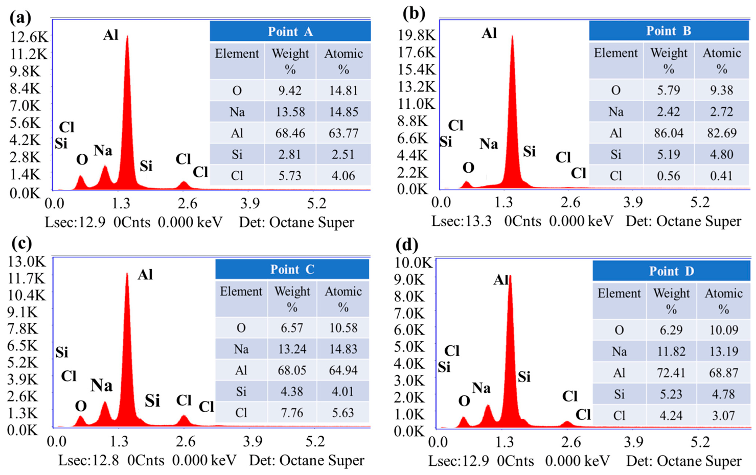
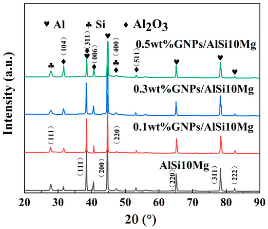
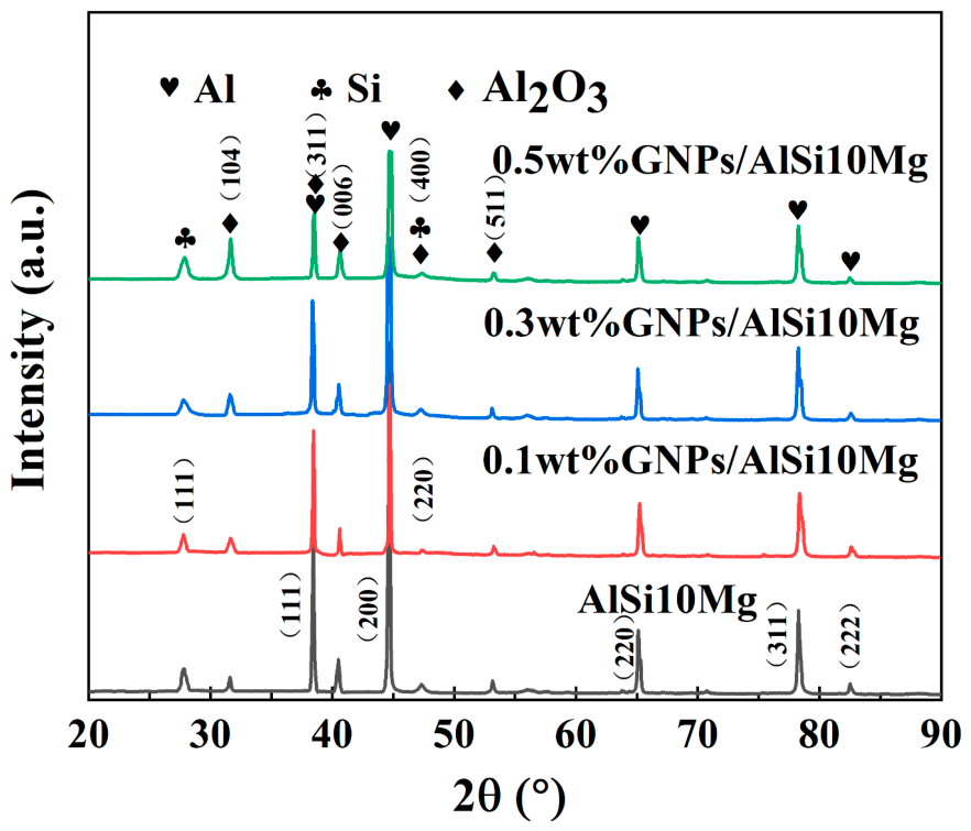
To further understand the corrosion behavior reflected by the mass loss data, the corrosion products were characterized using EDS and XRD. The EDS point scan results presented in Figure 6 reveal that the corrosion products contain O, Na, Al, Si, and Cl elements. Combined with the XRD analysis results shown in Figure 7, the corrosion products are identified as Al2O3 and NaCl. In the 3.5 wt.% NaCl solution, the corrosion process of the aluminum alloy involves the following electrochemical reactions. The cathodic reaction is predominantly the oxygen reduction reaction [34], in which dissolved oxygen is reduced to hydroxide ions in the neutral chloride-containing solution:
O2 + 2H2O + 4e− → 4OH−
Figure 6.
The EDS point scan results of the corrosion products of GNPs/AlSi10Mg composites with varying GNPs contents fabricated by SLM: (a) AlSi10Mg alloy, (b) 0.1 wt.% GNPs/AlSi10Mg composite, (c) 0.3 wt.% GNPs/AlSi10Mg composite, (d) 0.5 wt.% GNPs/AlSi10Mg composite.
Figure 7.
XRD patterns of corrosion products of GNPs/AlSi10Mg composites with varying GNPs contents fabricated by SLM.
At the anode, aluminum undergoes dissolution, with each aluminum atom losing three electrons to form aluminum ions:
Al → Al3+ + 3e−
Subsequently, the Al3+ ions in the solution combine with the OH− ions generated from the cathodic reaction to form aluminum hydroxide precipitates on the alloy surface:
Al3+ + 3OH− → Al(OH)3↓
Upon dehydration during drying or aging, the aluminum hydroxide transforms into aluminum oxide:
2Al(OH)3 → Al2O3 + 3H2O
The presence of NaCl is attributed to crystallized salt deposits on the specimen surface after drying. It should be noted that the EDS analysis was performed as single-point measurements, which may not fully represent the compositional heterogeneity of the irregular and porous corrosion surface. Nevertheless, the single-point EDS results, combined with the bulk phase identification from XRD analysis, consistently confirm the presence of Al2O3 as the main corrosion products. The peak at approximately 31.88° in the XRD patterns corresponds to Al2O3. With increasing GNPs content, the intensity of this peak gradually increases, indicating that more Al2O3 is formed in the corrosion products. This is consistent with the proposed reaction pathway (reactions 3–4) and further supported by the EDS results (Figure 6).
The corrosion product layer on the AlSi10Mg alloy surface is loose and porous, allowing corrosive Cl− ions to readily penetrate through the underlying matrix. In contrast, the corrosion product layer on the GNPs/AlSi10Mg composite surfaces is relatively dense, effectively impeding the infiltration of corrosive ions. Therefore, the compactness of the corrosion products affects the corrosion resistance of the specimens. However, whether the improved corrosion resistance of the GNPs/AlSi10Mg composites is mainly attributable to the densification of the corrosion product layer remains unclear.
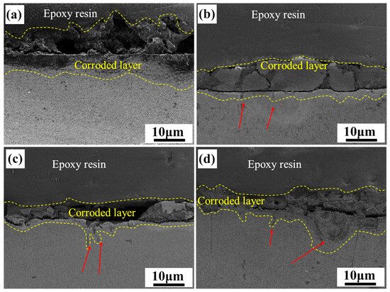
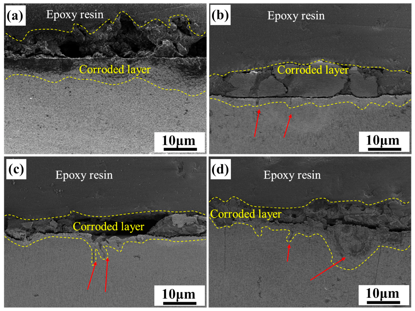
Figure 8 presents the cross-sectional morphologies of GNPs/AlSi10Mg composites with varying GNPs contents after 60 days of immersion in 3.5 wt.% NaCl solution. As shown in Figure 8a, the corrosion product layer on the AlSi10Mg alloy is loose and porous, and corrosive Cl− ions have penetrated the product layer and attacked the underlying aluminum matrix, resulting in uniform corrosion on the specimen surface with relatively slow corrosion propagation. For the 0.1 wt.% GNPs/AlSi10Mg composite (Figure 8b), visible through-cracks are present in the thick and dense product layer, and the corrosive medium has propagated along these cracks into the matrix. When the GNPs content is further increased to 0.3 wt.% and 0.5 wt.% (Figure 8c,d), the product layer becomes increasingly loose, porous, and prone to spallation, while corrosion cracks extend significantly deeper into the matrix, leading to substantially aggravated corrosion damage. These results indicate that after 60 days of prolonged corrosion, the physical barrier effect of graphene has been completely compromised. Once the corrosive medium penetrates the GNPs/matrix interface, GNPs act as cathodes due to their higher electrochemical potential, forming galvanic couples with the aluminum matrix and accelerating anodic dissolution of the matrix. With increasing GNPs content, the number of GNPs/matrix interfaces increases, intensifying the galvanic corrosion effect, which in turn leads to higher corrosion rates and progressive degradation of corrosion resistance.
Figure 8.
Cross-section morphology of GNPs/AlSi10Mg composites with varying GNPs contents fabricated by SLM: (a) AlSi10Mg alloy, (b) 0.1 wt.% GNPs/AlSi10Mg composite, (c) 0.3 wt.% GNPs/AlSi10Mg composite, (d) 0.5 wt.% GNPs/AlSi10Mg composite.
3.3. Effect of Corrosion Duration on the Electrochemical Impedance
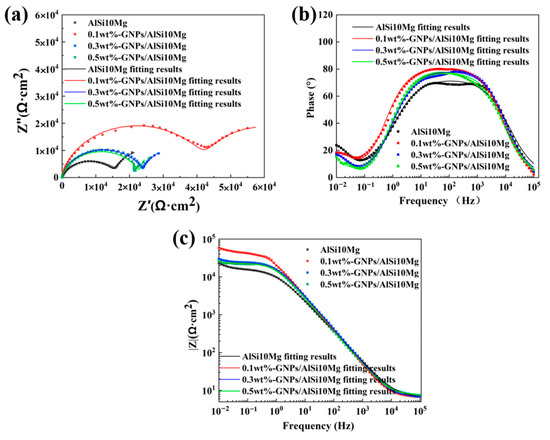
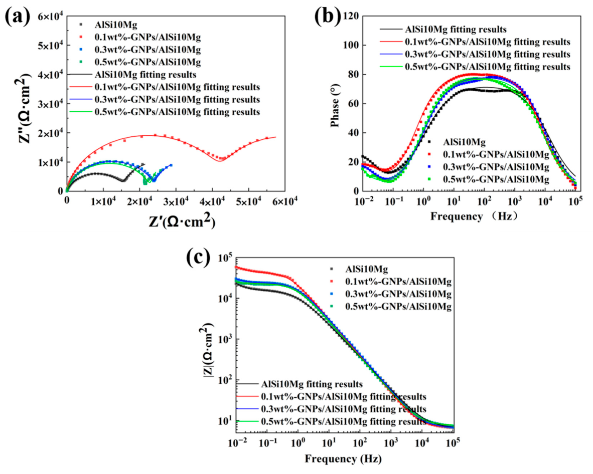
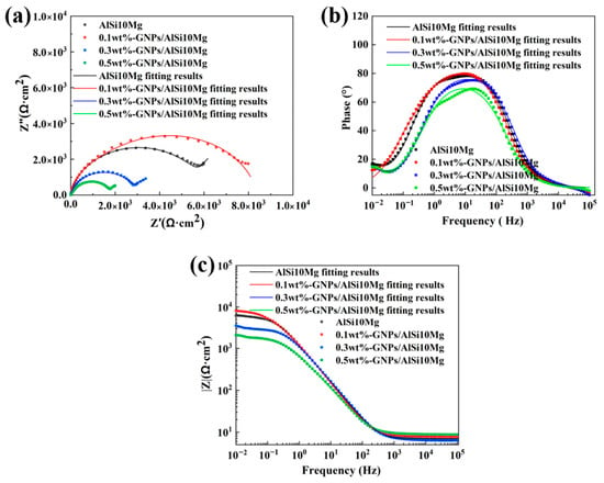
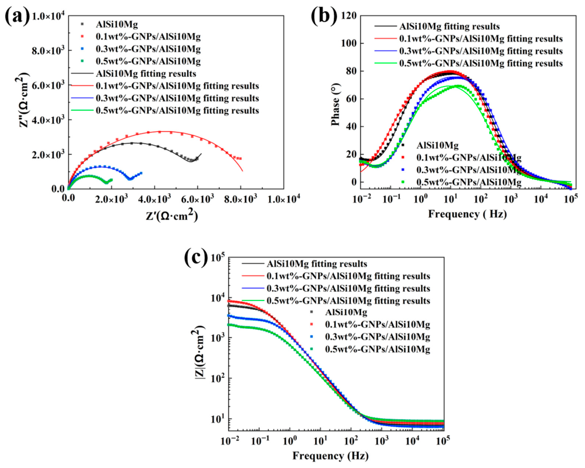
To investigate the effect of corrosion duration on the corrosion resistance of GNPs/AlSi10Mg composites, EIS was employed to study the corrosion behavior of the specimens in 3.5 wt.% NaCl solution. Figure 9 presents the impedance spectra and corresponding fitting results of SLM-fabricated GNPs/AlSi10Mg composites with varying GNPs contents at room temperature. In the Nyquist plots shown in Figure 9a, the horizontal and vertical axes represent the real (Z′) and imaginary (Z″) parts of the impedance, respectively. All specimens exhibit a capacitive arc in the high-frequency region and an inclined straight line in the low-frequency region. The high-frequency capacitive arc is associated with charge transfer and the double layer, arising from the resistance-capacitance relaxation process induced by the charge transfer resistance (Rct) and double-layer capacitance (Cdl) under Cl− action. This process is suppressed by the dispersion of interfacial impedance and the inhomogeneity of adsorbed species on the aluminum alloy surface, thereby influencing the corrosion rate [21,35]. The inclined straight line in the low-frequency region reflects the capacitive behavior associated with the porous electrode effect, corresponding to the CPE element in the equivalent circuit. Accordingly, the dissolution of SLM-fabricated GNPs/AlSi10Mg composites is governed by both the charge transfer process and the capacitive behavior of the porous electrode structure. As GNPs content increases, the radius of the high-frequency capacitive arc first expands and then contracts. Generally, a larger arc radius corresponds to higher impedance, greater resistance to corrosion reactions, and thus superior corrosion resistance [36]. This indicates that the 0.1 wt.% GNPs/AlSi10Mg composite exhibits the best corrosion resistance. This is attributed to the synergistic effect of two factors. (a) Uniformly dispersed GNPs fill micropores and microcracks, increasing densification and acting as a physical barrier that impedes the diffusion of corrosive ions. (b) GNPs refine the grain structure (from 15.61 µm to 13.29 µm), promoting the formation of a denser and more stable passive film that further hinders charge transfer. The improvement in Rct is not linearly proportional to the GNPs content, but rather reflects the critical role of achieving a continuous effective barrier network at a relatively low percolation threshold. The combination of these synergistic mechanisms accounts for the disproportionately large improvement at 0.1 wt.% GNPs. Moreover, with further increases in GNPs content, the capacitive arc diameter gradually decreases but remains larger than that of the AlSi10Mg alloy, indicating that the addition of GNPs enhances the corrosion resistance of SLM-fabricated GNPs/AlSi10Mg composites [37]. The decline in corrosion resistance at higher GNPs contents is primarily attributed to GNPs agglomeration, which weakens the interfacial bonding between GNPs and the matrix and facilitates the ingress and diffusion of corrosive ions [38].
Figure 9.
The experimental EIS results and CNLS results of GNPs/AlSi10Mg composites with varying GNPs contents produced by using SLM into a naturally aerated 0.56M NaCl solution at environmental temperature: (a) Nyquist, (b) Bode-phase, and (c) Bode plots.
Figure 9b presents the Bode plots. All four specimens exhibit a peak in the medium-frequency region with phase angles approaching 70–80°, indicating the formation of an intact oxide film on the alloy surface. In addition, a small peak appears in the low-frequency region for all four specimens, which is mainly associated with the presence of Al(OH)3 flocculent on the alloy surface. This flocculent acts as a limited diffusion layer, restricting Cl− migration on the aluminum alloy surface and inhibiting the charge transfer process. In Bode plots, the impedance magnitude in the low-frequency region represents the total impedance of the specimen and its corrosion resistance, whereas the impedance magnitude at the high-frequency limit corresponds to the solution resistance [1,39]. As shown in Figure 9c, the total impedance modulus in the low-frequency region decreases in the order of 0.1 wt.% GNPs/AlSi10Mg > 0.3 wt.% GNPs/AlSi10Mg > 0.5 wt.% GNPs/AlSi10Mg > AlSi10Mg, which reflects the ranking of corrosion resistance of the specimens. The impedance values of the different specimens converge at a single point in the high-frequency region, demonstrating the stability and consistency of the solution resistance.
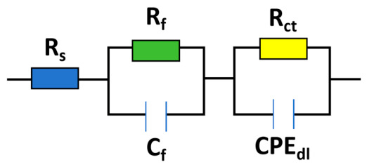
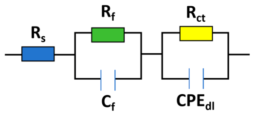
The equivalent circuit model shown in Figure 10 was employed to fit the EIS data of the uncorroded specimens and elucidate the corrosion process. The equivalent circuit model has two time constants, consisting of solution resistance (), a parallel combination of film resistance () and film capacitance (), and a parallel combination of charge transfer resistance () and a constant phase element for the double layer (). In the fitting process, the ideal double-layer capacitance () was replaced by to account for the non-ideal capacitive behavior due to the inhomogeneous electrode surface. The ideal double-layer capacitance () is expressed as [21]:
where is the CPE magnitude and the exponent is associated with the distribution of time constants. In this circuit, and correspond to the oxide film resistance and the charge transfer resistance, respectively. The fitting quality was evaluated using the chi-square value (χ2) obtained from ZSimpWin software, which represents the square of the standard deviation between the raw data and the calculated values, reflecting the fit goodness. All chi-square values were below 1 × 10⁻³, indicating good fitting quality. The electrochemical parameters obtained from the equivalent circuit fitting are summarized in Table 3.
Figure 10.
Equivalent circuit model.
Table 3.
The EIS fitting results of GNPs/AlSi10Mg composites with varying GNPs contents fabricated by SLM.
With increasing GNPs content, both the film resistance () and charge transfer resistance () initially increase and then decrease. The 0.1 wt.% GNPs/AlSi10Mg composite exhibits and values of (3.54 ± 0.38) × 104 and (4.30 ± 0.46) × 104 Ω·cm2, respectively. Compared with the AlSi10Mg alloy ( = (1.96 ± 0.22) × 104 Ω·cm2, = (1.60 ± 0.18) × 104 Ω·cm2), the composite specimens exhibit higher resistance values. As the GNPs content further increases, shows a decreasing trend, indicating a reduction in the corrosion resistance of the composites in NaCl solution, which is consistent with the mass loss results presented in Section 3.2. The impermeability of graphene effectively protects the matrix and retards the propagation of corrosion. Consequently, the GNPs/AlSi10Mg composites exhibit superior corrosion resistance compared to the AlSi10Mg alloy.
Figure 11 presents the impedance spectra of SLM-fabricated GNPs/AlSi10Mg composites with varying GNPs contents after 50 days of immersion in 3.5 wt.% NaCl solution at room temperature, with the corresponding equivalent circuit fitting results summarized in Table 4. Compared with the initial stage (Figure 9a), the radius of the capacitive arc for all specimens decreases markedly after 50 days of corrosion, as shown in Figure 11a, indicating significant degradation of corrosion resistance. The reduced peak range in the medium-to-low frequency region of the Bode plots reflects changes in the oxide film on the specimen surface, while the notable decrease in impedance modulus at low frequencies further confirms the diminished barrier capability of the corrosion product layer against ion transport. After 50 days of corrosion, the specimens with higher GNPs contents exhibit a more pronounced decrease in total impedance at low frequencies. The fitting results (Table 4) show that both the film resistance () and charge transfer resistance () of all specimens decrease significantly compared with the initial stage. The values for the AlSi10Mg, 0.1 wt.%, 0.3 wt.%, and 0.5 wt.% GNPs/AlSi10Mg composites are (5.85 ± 0.58) × 103, (7.40 ± 0.72) × 103, (2.92 ± 0.25) × 103, and (1.79 ± 0.18) × 103 Ω·cm2, respectively. Thus, the corrosion resistance ranking at 50 days is 0.1 wt.% GNPs/AlSi10Mg > AlSi10Mg > 0.3 wt.% GNPs/AlSi10Mg > 0.5 wt.% GNPs/AlSi10Mg, which differs from that observed in the initial stage. This can be regarded as a critical transition stage in the corrosion behavior of GNPs/AlSi10Mg composites. For the 0.1 wt.% GNPs/AlSi10Mg composite, the penetration of corrosive ions along the GNPs/matrix interface is effectively hindered by the impermeability of graphene, thereby retarding corrosion propagation. At higher GNPs contents, however, graphene agglomeration reduces its impermeability and introduces more corrosion pathways, while the exposed graphene may act as cathodic sites and initiate micro-galvanic coupling with the aluminum matrix, further accelerating the corrosion process [40,41].
Figure 11.
The experimental EIS results and CNLS results of GNPs/AlSi10Mg composites with varying GNPs contents produced by using SLM into a naturally aerated 0.56M NaCl solution at environmental temperature after 50 days immersion: (a) Nyquist, (b) Bode phase, and (c) Bode plots.
Table 4.
The EIS fitting results of GNPs/AlSi10Mg composites with varying GNPs contents fabricated by SLM in the aerated 3.5 wt.% NaCl solution for 50 days.
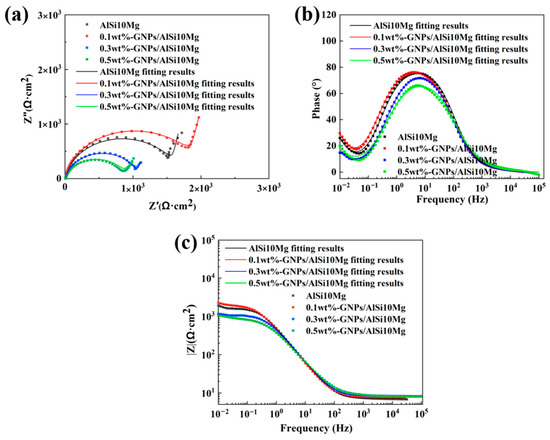
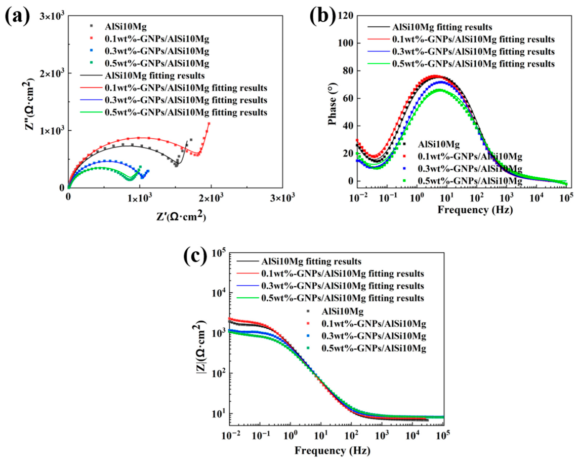
Figure 12 presents the impedance spectra of SLM-fabricated GNPs/AlSi10Mg composites with varying GNPs contents after 60 days of immersion in 3.5 wt.% NaCl solution at room temperature, along with the corresponding equivalent circuit fitting results (Table 5). Compared with the initial stage (Figure 9a) and transition stage (Figure 11a), the diameter of the capacitive arc continues to decrease as corrosion time further increases, as shown in Figure 12a, indicating further degradation of corrosion resistance. After 60 days of corrosion, the values for the AlSi10Mg, 0.1 wt.%, 0.3 wt.%, and 0.5 wt.% GNPs/AlSi10Mg composites are (1.90 ± 0.18) × 103, (1.60 ± 0.15) × 103, (1.07 ± 0.11) × 103, and (8.91 ± 0.89) × 102 Ω·cm2, respectively. Thus, the corrosion resistance ranking at 60 days is AlSi10Mg > 0.1 wt.% GNPs/AlSi10Mg > 0.3 wt.% GNPs/AlSi10Mg > 0.5 wt.% GNPs/AlSi10Mg, which differs from that observed in the initial stage and 50 days. Notably, all GNPs/AlSi10Mg composites exhibit inferior corrosion resistance to the AlSi10Mg alloy at this long-term stage. This phenomenon suggests a mechanism in which the high electrical conductivity of graphene may play a key role. As the immersion time increases, the corrosive medium gradually penetrates the interface between the metal and graphene, disrupting the barrier effect. Under such conditions, graphene may act as a local cathode, leading to galvanic corrosion between GNPs and the surrounding Al matrix. This interpretation is consistent with the observed performance reversal and the morphological features shown in Figure 8. However, direct experimental evidence, such as local electrochemical measurements or cross-sectional TEM analysis, would be required for definitive confirmation of the galvanic coupling at the GNPs/matrix interface. A higher GNPs content introduces more “metal–graphene” interfaces due to agglomeration, which accelerates the corrosion rate and compromises the corrosion resistance of the composites. Therefore, after 60 days of corrosion, the corrosion resistance of the specimens indicates that GNPs do not improve the corrosion resistance of the alloy but rather accelerate its corrosion under prolonged exposure.
Figure 12.
The experimental EIS results and CNLS results of GNPs/AlSi10Mg composites with varying GNPs contents produced by using SLM into a naturally aerated 0.56M NaCl solution at environmental temperature after 60 days immersion: (a) Nyquist, (b) Bode-phase, and (c) Bode plots.
Table 5.
The EIS fitting results of GNPs/AlSi10Mg composites with varying GNPs contents fabricated by SLM in the aerated 3.5 wt.% NaCl solution for 60 days.
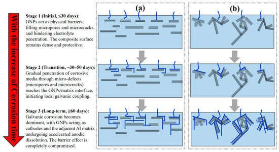
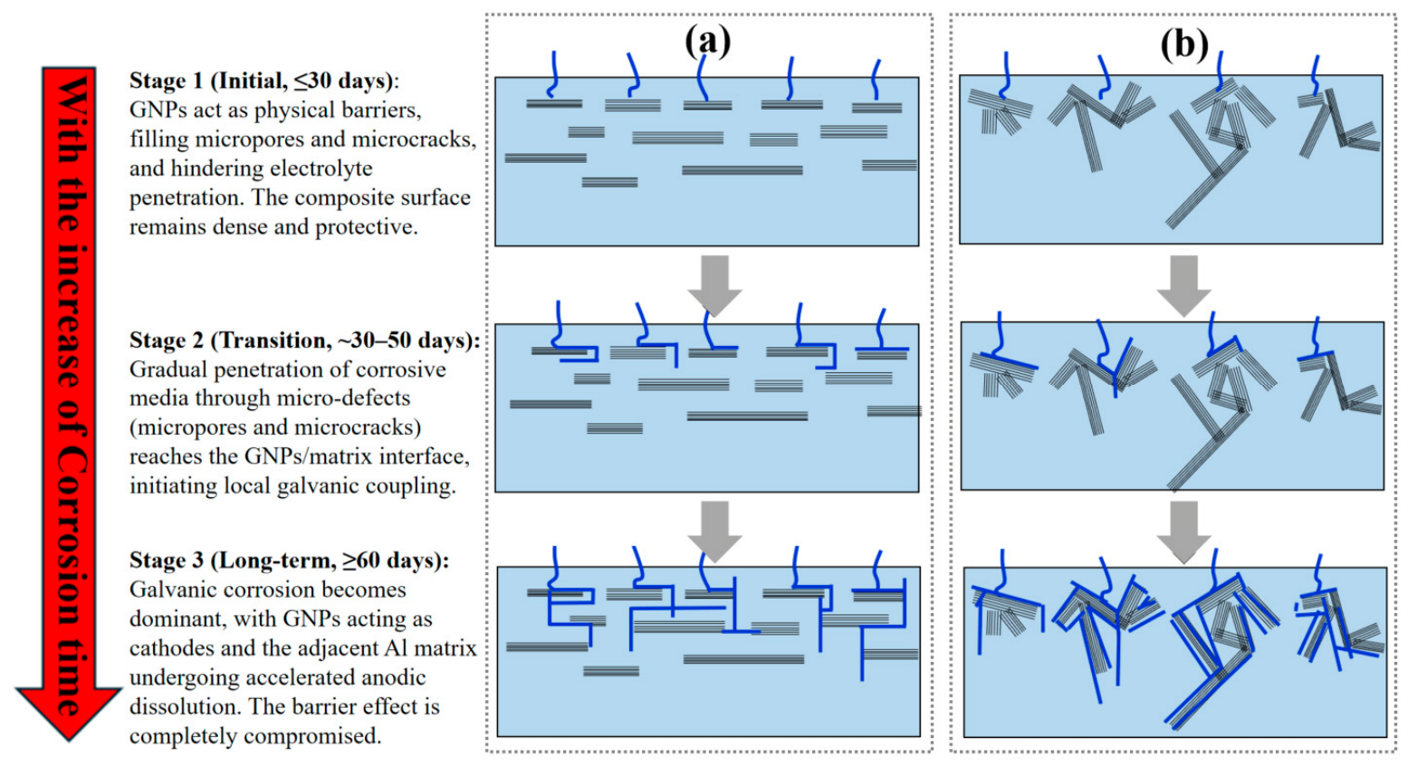
Figure 13 presents proposed schematic diagrams illustrating the three-stage corrosion mechanisms for uniformly dispersed and agglomerated GNPs in the composites. As shown in Figure 13a, when GNPs are uniformly dispersed in the GNPs/AlSi10Mg composite, the embedded GNPs fill the pores and microcracks generated during SLM processing, forming a dense composite with good interfacial bonding between GNPs and the matrix. When the specimen is exposed to corrosive media, the dense surface structure provides effective protection. With increasing corrosion time, the barrier effect of graphene gradually weakens, and its ability to impede electrolyte diffusion diminishes. Meanwhile, the good interfacial bonding enables graphene to hinder crack growth, thereby reducing corrosion pathways. Eventually, when the corrosive medium eventually reaches the vicinity of GNPs, localized corrosion of the composite is accelerated. As illustrated in Figure 13b, when GNPs are agglomerated, the composite surface contains micropores. The corrosive solution diffuses through pores or along cracks and encounters obstacles when reaching the GNPs. However, owing to the gaps between agglomerated GNPs and the weak interfacial bonding with the matrix, the corrosive electrolyte readily penetrates the matrix. Consequently, galvanic corrosion occurs at the GNPs/matrix boundaries and propagates further, compromising the barrier effect of GNPs and leading to their detachment. Eventually, when the corrosive electrolyte completely fills the interface between GNPs and the aluminum matrix, graphene acts as a cathode relative to the aluminum matrix. The addition of agglomerated GNPs increases the number and area of cathodic sites, thereby intensifying the galvanic corrosion between graphene and the aluminum matrix. In essence, grain refinement and uniform GNPs dispersion enhance short-term corrosion resistance, while agglomeration-induced porosity and interfacial degradation lead to long-term galvanic corrosion.
Figure 13.
Proposed schematic diagrams illustrating the time-dependent corrosion mechanisms of GNPs/AlSi10Mg composites with different GNPs distribution states. (a) Corrosion process with uniformly dispersed GNPs; (b) corrosion process with agglomerated GNPs.
The findings of this study reveal an important practical limitation of GNPs/AlSi10Mg composites for corrosion-resistant applications. Although the addition of 0.1 wt.% GNPs significantly enhance the corrosion resistance during short-term exposure (≤30 days), this beneficial effect is reversed after prolonged immersion (60 days), where the composites exhibit inferior corrosion resistance compared with the unreinforced AlSi10Mg alloy. This suggests that the application of GNPs/AlSi10Mg composites should be carefully considered based on the expected service environment and exposure duration. For short-term or intermittent exposure to chloride-containing environments, the improved corrosion resistance may be advantageous. However, for long-term service applications, additional protective measures, such as surface coatings, anodizing, or post-processing treatments, would be necessary to mitigate the galvanic corrosion effect induced by GNPs. Future work should focus on optimizing the GNPs distribution, reducing porosity, and developing hybrid reinforcement strategies to overcome the long-term degradation issue.
4. Conclusions
The present study systematically investigates the effect of GNPs content and corrosion duration on the corrosion resistance of SLM-fabricated GNPs/AlSi10Mg composites, revealing the distinct roles of GNPs in short-term and long-term corrosion. The main conclusions can be summarized as follows:
(1) The addition of GNPs refines the microstructure of the composites, reducing the average grain size from 15.61 µm to 13.29 µm. At a GNPs content of 0.1 wt.%, GNPs are uniformly dispersed in the aluminum matrix with favorable interfacial bonding, and the composite exhibits a high densification level without obvious porosity.
(2) Corrosion resistance varies significantly with corrosion time. In the short term (≤30 days), GNPs addition improves the corrosion resistance of the composites, with the ranking 0.1 wt.% GNPs/AlSi10Mg > 0.3 wt.% GNPs/AlSi10Mg > 0.5 wt.% GNPs/AlSi10Mg > AlSi10Mg. In the long term (60 days); however, the ranking reverses to AlSi10Mg > 0.1 wt.% GNPs/AlSi10Mg > 0.3 wt.% GNPs/AlSi10Mg > 0.5 wt.% GNPs/AlSi10Mg, indicating that GNPs addition deteriorates the long-term corrosion resistance.
(3) The short-term beneficial effect (≤30 days) is attributed to the uniform dispersion of GNPs, which fills micropores and microcracks, enhances densification, and acts as a physical barrier against corrosive ions, along with favorable interfacial bonding that hinders crack growth and reduces corrosion pathways.
(4) The long-term detrimental effect (60 days) arises from galvanic corrosion. The corrosive medium gradually penetrates through micropores and microcracks to the GNPs/matrix interface, initiating galvanic corrosion between GNPs and the matrix and rendering the barrier effect ineffective. The addition of GNPs increases both the number and total area of cathodic sites in the matrix alloy, thereby accelerating the corrosion process. This long-term galvanic effect eventually outweighs the short-term barrier benefit.
Author Contributions
Conceptualization, L.W. and Z.Z.; methodology, L.W. and K.L.; software, L.W.; validation, L.W., Z.Z. and P.B.; formal analysis, L.W. and K.L.; investigation, L.W.; resources, L.W.; data curation, L.W., Z.Z. and K.L.; writing—original draft preparation, L.W.; writing—review and editing, Z.Z., P.B., K.L.; visualization, L.W., Z.Z., K.L.; supervision, L.W.; project administration, L.W.; funding acquisition, L.W., Z.Z., P.B., K.L. All authors have read and agreed to the published version of the manuscript.
Funding
This research was funded by the Fundamental Research Program of Shanxi Province (202303021222304); the Scientific and Technological Innovation Programs of Higher Education Institutions in Shanxi (2023L356); the Foundation of State Key Laboratory of Extreme Environment Optoelectronic Dynamic Measurement Technology and Instrument (2024-SYSJJ-03).
Data Availability Statement
The original contributions presented in this study are included in the article. Further inquiries can be directed to the corresponding authors.
Conflicts of Interest
The authors declare no conflicts of interest.
References
- Zhao, Z.Y.; Bai, P.K.; Du, W.; Liu, B.; Chen, D.; Li, X.P.; Wu, L.Y. An overview of graphene and its derivatives reinforced metal matrix composites: Preparation, properties and applications. Carbon 2020, 170, 302–326. [Google Scholar] [CrossRef] [Scilit]
- Li, X.; Yi, D.; Liu, B.; Zhang, J.; Yang, J.; Wang, Z.; Li, Z.; Xu, G. Graphene-strengthened Inconel 625 alloy fabricated by selective laser melting. Mater. Sci. Eng. A 2020, 798, 140099. [Google Scholar] [CrossRef] [Scilit]
- Li, X.P.; Ji, G.; Chen, Z.; Addad, A.; Wu, Y.; Wang, H.W.; Vleugels, J.; Van Humbeeck, J.; Kruth, J.P. Selective laser melting of nano-TiB2 decorated AlSi10Mg alloy with high fracture strength and ductility. Acta Mater. 2017, 129, 183–193. [Google Scholar] [CrossRef] [Scilit]
- Lin, Z.; Sun, Z.; Luo, B.; Tang, G.; Shi, P.; Lu, H.; Li, Q.; Zheng, T.; Zhou, B.; Liu, C.; et al. Overcoming strength-ductility trade-off in bimodal metal matrix composite with 3D graphene-strengthened hetero-interface. Carbon 2024, 230, 119630. [Google Scholar] [CrossRef] [Scilit]
- Chen, L.; Li, Z.; Yan, S.; Luo, H.; Li, X.; Sha, A. Enhanced mechanical properties of graphene oxide reinforced aluminum with lamellar microstructure and crystallographic alignment. Carbon 2025, 245, 120792. [Google Scholar] [CrossRef] [Scilit]
- Wang, W.; Cui, C.; Xia, F.; Xu, W.; Gang, T.; Chen, L. A first principles investigation into the mechanical properties and the strengthening mechanism of the graphene/aluminum interface structure. Sci. Rep. 2025, 15, 38571. [Google Scholar] [CrossRef] [Scilit]
- Shu, Q.; Jia, Z.; Cao, L.; Li, J.; Chen, B. A comparative study of carbon nanotubes and graphene for metal matrix compo-sites: Insights from simulation and experimentation. Vacuum 2025, 239, 114429. [Google Scholar] [CrossRef] [Scilit]
- Jalali, M.; Hassanzadeh, N.; Alizadeh, R.; Langdon, T.G. Graphene-reinforced metal matrix composites produced by high-pressure torsion: A review. J. Mater. Sci. 2024, 59, 20900–20928. [Google Scholar] [CrossRef] [Scilit]
- Huang, J.; Liao, J.; Li, Y.; Fan, Z.; Wang, Z.; Guo, Z.; Ruan, H.; Zhang, G.; Sun, L. Material Processing of Chemically Modi-fied Graphene: Some Challenges and Solutions. Acc. Chem. Res. 2026, 59, 2125–2138. [Google Scholar]
- Kuchariková, L.; Tillová, E.; Šurdová, Z.; Chalupová, M.; Zatkalíková, V.; Illichmanová, E.; Švecová, I. The Effect of Surface Corrosion Damage and Fe Content on the Fatigue Life of an AlSi7Mg0.6 Cast Alloy Used in the Electric Automotive Industry. Metals 2025, 15, 1222. [Google Scholar] [CrossRef] [Scilit]
- Wu, J.; Pisula, W.; Müllen, K. Graphenes as potential material for electronics. Chem. Rev. 2007, 107, 718–747. [Google Scholar] [CrossRef] [Scilit]
- Allen, M.J.; Tung, V.C.; Kaner, R.B. Honeycomb carbon: A review of graphene. Chem. Rev. 2010, 110, 132–145. [Google Scholar] [CrossRef] [Scilit]
- Raman, R.K.; Banerjee, P.; Lobo, D.E.; Gulapalli, H.; Sumandasa, M.; Kumar, A.; Choudhary, L.; Tkacz, R.; Ajayan, P.M.; Majumder, M. Protecting copper from electrochemical degradation by graphene coating. Carbon 2012, 50, 4040–4045. [Google Scholar] [CrossRef] [Scilit]
- Novoselov, K.S.; Geim, A.K.; Morozov, S.V.; Jiang, D.; Zhang, Y.; Dubonos, S.V.; Grigorieva, I.V.; Firsov, A.A. Electric field effect in atomically thin carbon films. Science 2004, 306, 666–669. [Google Scholar] [CrossRef] [Scilit]
- Prasai, D.; Tuberquia, J.C.; Harl, R.R.; Jennings, G.K.; Bolotin, K.I. Graphene: Corrosion-inhibiting coating. ACS Nano 2012, 6, 1102–1108. [Google Scholar] [CrossRef] [Scilit]
- Compton, O.C.; Kim, S.; Pierre, C.; Torkelson, J.M.; Nguyen, S.T. Crumpled graphene nanosheets as highly effective barrier property enhancers. Adv. Mater. 2010, 22, 4759–4763. [Google Scholar] [CrossRef] [Scilit]
- Liu, X.; Xu, T.; Li, Y.; Zang, Z.; Peng, X.; Wei, H.; Zhan, W.; Wang, Y. Enhanced X-ray photon response in solu-tion-synthesized CsPbBr3 nanoparticles wrapped by reduced graphene oxide. Sol. Energy Mater. Sol. Cells 2018, 187, 249–254. [Google Scholar] [CrossRef] [Scilit]
- Schriver, M.; Regan, W.; Gannett, W.J.; Zaniewski, A.M.; Crommie, M.F.; Zettl, A. Graphene as a long-term metal oxidation barrier: Worse than nothing. ACS Nano 2013, 7, 5763–5768. [Google Scholar] [CrossRef] [Scilit]
- Rashad, M.; Pan, F.; Yu, Z.; Asif, M.; Lin, H.; Pan, R. Investigation on microstructural, mechanical and electrochemical properties of aluminum composites reinforced with graphene nanoplatelets. Prog. Nat. Sci. Mater. Int. 2015, 25, 460–470. [Google Scholar] [CrossRef] [Scilit]
- Wu, L.; Zhao, Z.; Bai, P.; Zhang, Z.; Li, Y.; Liang, M.; Du, W. The Effect of Silicon Phase Morphology on Microstructure and Properties of AlSi10Mg Alloys Fabricated by Selective Laser Melting. Materials 2022, 15, 8786. [Google Scholar] [CrossRef] [Scilit]
- Qiang, Y.; Zhang, S.; Zhao, H.; Tan, B.; Wang, L. Enhanced anticorrosion performance of copper by novel N-doped carbon dots. Corros. Sci. 2019, 161, 108193. [Google Scholar] [CrossRef] [Scilit]
- Duarte, T.; Meyer, Y.A.; Osório, W.R. The Holes of Zn Phosphate and Hot Dip Galvanizing on Electrochemical Behaviors of Multi-Coatings on Steel Substrates. Metals 2022, 12, 863. [Google Scholar] [CrossRef] [Scilit]
- Barcia, O.E.; D’Elia, E.; Frateur, I.; Mattos, O.R.; Pébère, N.; Tribollet, B. Application of the impedance model of de Levie for the characterization of porous electrodes. Electrochim. Acta 2002, 47, 2109–2116. [Google Scholar] [CrossRef] [Scilit]
- Meyer, Y.A.; Bonatti, R.S.; Bortolozo, A.D.; Osório, W.R. Electrochemical behavior and compressive strength of Al–Cu/xCu composites in NaCl solution. J. Solid State Electrochem. 2021, 25, 1303–1317. [Google Scholar] [CrossRef] [Scilit]
- Louvis, E.; Fox, P.; Sutcliffe, C.J. Selective laser melting of aluminium components. J. Mater. Process. Technol. 2011, 211, 275–284. [Google Scholar] [CrossRef] [Scilit]
- Wang, L.; Feng, S.Z.; Wang, Y.G.; Zhao, X.; Ge, J.X.; Gao, T.X.; Di, F.Q. Porosity defects in additively manufactured metal materials: Formation mechanisms, impact on performance and regulation. Int. Mater. Rev. 2026, 71, 97–128. [Google Scholar] [CrossRef] [Scilit]
- Wu, L.Y.; Zhao, Z.Y.; Bai, P.K.; Du, W.; Li, X.P.; Cheng, C.; Wang, Y.Q.; Wei, H.L.; Yan, G.Z.; Zhang, Y.T. Wear resistance of graphene nano-platelets (GNPs) reinforced AlSi10Mg matrix composite prepared by SLM. Appl. Surf. Sci. 2020, 503, 144156. [Google Scholar] [CrossRef] [Scilit]
- Yuan, Q.H.; Zhou, G.H.; Liao, L.; Liu, Y.W.; Luo, L.; Liu, Y. Interfacial structure in AZ91 alloy composites reinforced by graphene nanosheets. Carbon 2018, 127, 177–186. [Google Scholar] [CrossRef] [Scilit]
- Akram, J.; Chalavadi, P.; Pal, D.; Stucker, B. Understanding grain evolution in additive manufacturing through modeling. Addit. Manuf. 2018, 21, 255–268. [Google Scholar] [CrossRef] [Scilit]
- Bourell, D.; Kruth, J.P.; Leu, M.; Levy, G.; Rosen, D.; Beese, A.M.; Clare, A. Materials for additive manufacturing. CIRP Ann. 2017, 66, 659–681. [Google Scholar] [CrossRef] [Scilit]
- Wang, J.; Guo, L.N.; Lin, W.M.; Chen, J.; Zhang, S.D.; Chen, T.; Zhu, Y.T. Effect of the graphene content on the micro-structures and properties of graphene/aluminum composites. New Carbon Mater. 2019, 34, 275–285. [Google Scholar] [CrossRef] [Scilit]
- Tunc, I.; Karahan, B.D.; Keles, O.A. Study on the corrosion behavior of 7072/3004/7072 clad aluminum alloy in different media. J. Mater. Eng. Perform. 2020, 29, 4506–4514. [Google Scholar] [CrossRef] [Scilit]
- Saxena, M.; Modi, O.P.; Yegneswaran, A.H.; Rohatgi, P.K. Corrosion characteristics of cast aluminum alloy-3 wt% graphite particulate composites in different environments. Corros. Sci. 1987, 27, 249–256. [Google Scholar] [CrossRef] [Scilit]
- Mamizadeh Janqour, L.; Sarabi, A.A. Optimization of coating process parameters and surface characterization for vana-dium-based conversion coating on 2024 aluminum alloy. Prog. Org. Coat. 2019, 133, 33–43. [Google Scholar] [CrossRef] [Scilit]
- Dutta, A.; Saha, S.K.; Adhikari, U.; Banerjee, P.; Sukul, D. Effect of substitution on corrosion inhibition properties of 2-(substituted phenyl) benzimidazole derivatives on mild steel in 1 M HCl solution: A combined experimental and theoreti-cal approach. Corros. Sci. 2017, 123, 256–266. [Google Scholar] [CrossRef] [Scilit]
- Chen, Y.; Zhang, J.; Gu, X.; Dai, N.; Qin, P.; Zhang, L. Distinction of corrosion resistance of selective laser melted Al–12Si alloy on different planes. J. Alloys Compd. 2018, 747, 648–658. [Google Scholar] [CrossRef] [Scilit]
- Liu, W.; Liu, Y.; Lin, Y.; Zhang, G.; Wang, Y.; Li, J. Effects of graphene on structure and corrosion resistance of plasma electrolytic oxidation coatings formed on D16T Al alloy. Appl. Surf. Sci. 2019, 475, 645–659. [Google Scholar] [CrossRef] [Scilit]
- Liu, J.Y.; Gao, F.; Liu, X.Y.; Li, C.Y.; Tian, P.; Gao, M.Y.; Xie, H.L.; Liu, C.Z. Preparation and Properties of Graphene Nano-platelet (GNP) and Silicon Carbide Nanowire (SiCnw) Hybrid Synergistic Reinforced 2024 Aluminum Matrix Composites. JOM 2026, 78, 5064. [Google Scholar] [CrossRef] [Scilit]
- Cabrini, M.; Lorenzi, S.; Pastore, T.; Pellegrini, S.; Manfredi, D.; Fino, P.; Biamino, S.; Badini, C. Effect of heat treat-ment on corrosion resistance of DMLS AlSi10Mg alloy. Electrochim. Acta 2016, 206, 346–355. [Google Scholar] [CrossRef] [Scilit]
- Wu, Y.; Zhu, X.; Zhao, W.; Wang, Y.; Li, C.; Li, J. Corrosion mechanism of graphene coating with different defect levels. J. Alloys Compd. 2019, 777, 135–144. [Google Scholar] [CrossRef] [Scilit]
- Kirkland, N.T.; Schiller, T.; Medhekar, N.; Birbilis, N. Exploring graphene as a corrosion protection barrier. Corros. Sci. 2012, 56, 1–4. [Google Scholar] [CrossRef] [Scilit]

Disclaimer/Publisher’s Note: The statements, opinions and data contained in all publications are solely those of the individual author(s) and contributor(s) and not of MDPI and/or the editor(s). MDPI and/or the editor(s) disclaim responsibility for any injury to people or property resulting from any ideas, methods, instructions or products referred to in the content. |
© 2026 by the authors. Licensee MDPI, Basel, Switzerland. This article is an open access article distributed under the terms and conditions of the Creative Commons Attribution (CC BY) license.