


Abstract
Binder-jetted metallic components retain residual porosity after sintering, which can substantially affect their mechanical and tribological performance. This study clarifies how sintering-induced pore evolution and Cu infiltration influence the wear mechanisms of binder-jetted STS316L. STS316L specimens were sintered at 1100, 1200, and 1300 °C, and corresponding Cu/STS316L composites were fabricated by molten Cu infiltration. Their microstructures and wear behavior were analyzed using Filed-emission scanning electron microscopy (FE-SEM), Energy-dispersive X-ray spectroscopy (EDS), Confocal laser scanning microscopy (CLSM), X-ray diffraction (XRD), and cross-sectional Transmission electron microscopy (TEM). As the sintering temperature increased, the relative density and hardness of the sintered specimens increased from 72.75% to 80.69% and from 194 to 243.8 HV, respectively. Nevertheless, their average coefficient of friction increased from approximately 0.25 to 0.71, while the wear width and maximum depth increased from 932.8 to 1492.0 μm and from 24.7 to 60.3 μm, respectively. Abrasive and adhesive wear predominated at 1100 and 1200 °C, whereas repeated formation, cracking, and delamination of an approximately 2.5 μm thick oxygen-rich tribolayer caused severe oxidative delamination at 1300 °C. Cu infiltration increased the relative density to 90.68–95.69%. The composites exhibited similar friction behavior, with an average coefficient of friction of approximately 0.6, and were governed primarily by adhesive wear associated with Cu transfer and plastic deformation. These results demonstrate that increased densification does not necessarily improve wear resistance and that pore structure and Cu transfer critically determine the dominant wear mechanisms.
1. Introduction
Additive manufacturing (AM) has been widely applied across various industries owing to its ability to rapidly fabricate complex geometries that are difficult to produce using conventional manufacturing methods, while minimizing material waste and accommodating a broad range of materials such as metals, polymers, and ceramics [1,2,3]. Compared with conventional machining, metal additive manufacturing offers greater design freedom and eliminates the need for molds, enabling rapid prototyping and component lightweighting through optimized design. In addition, reductions in material consumption and manufacturing time have led to the expanding adoption of metal AM technologies in the production of automotive, aerospace, defense, and general industrial components [3,4]. Among powder-based AM processes, powder bed fusion (PBF) and binder jetting (BJT) are representative methods, both of which fabricate parts by selectively depositing powder layers ranging in thickness from several tens to several hundreds of micrometers. In particular, the BJT process employs a planar binder deposition, providing considerable flexibility in part geometry and build layout. These characteristics make BJT especially suitable for the mass production of small and complex components [1].
However, green bodies fabricated by the BJT process inherently exhibit high residual porosity due to process characteristics, which results in significantly reduced mechanical properties; therefore, post-processing routes are essential to enhance the mechanical performance of final components. As the mechanical properties and wear resistance of final parts are directly related to component lifetime and reliability, extensive studies have been conducted to improve the mechanical properties and wear resistance of BJT fabricated parts through the control of internal porosity and microstructure [1,5,6,7,8,9,10,11]. Typical post-processing routes include sintering and molten infiltration, which are commonly employed in conventional powder metallurgy. Wang et al. investigated the wear behavior of 316 stainless steel/bronze composites fabricated by the BJT process under marine environmental conditions and reported that the high ductility of Cu acted as a solid lubricant on the worn surface, resulting in superior wear resistance compared to conventional 316 stainless steel alloys [9]. Cui et al. comparatively analyzed the wear characteristics of 316/bronze, 420/bronze, and WC/bronze composites produced by BJT, identifying the dominant wear mechanisms and reporting that the wear resistance of each material was strongly influenced by porosity and the formation of a bronze lubricating layer [10]. Oh et al. and Jang et al. investigated the mechanical properties and microstructural changes in STS316L sintered bodies and Cu/STS316L composites as functions of sintering temperature and Cu content to fabricate Cu/STS316L composites with enhanced performance. Rig tests conducted on honeycomb-structured Cu/STS316L journal bearings fabricated under optimized conditions demonstrated an approximately 50% improvement in wear resistance compared with commercial products. These findings demonstrate the potential application of Cu/STS316L composites in wear-resistant sliding components, particularly journal bearings, in which friction stability and wear resistance directly affect service life and operational reliability [11,12]. Therefore, clarifying their tribological behavior and wear mechanisms is essential for evaluating and optimizing these composites for such applications. Despite these studies, the effect of the sintering-temperature-dependent pore structure of the STS316L skeleton on Cu infiltration and the resulting tribological behavior have not been sufficiently clarified. In particular, systematic comparisons linking pore evolution and Cu distribution to friction behavior, wear-track morphology, oxide-layer formation, subsurface damage, and counterface interaction in uninfiltrated and Cu-infiltrated specimens remain limited. Clarifying these relationships is important because sintering-induced pore evolution and Cu infiltration may affect not only density and hardness but also debris accommodation, material transfer, oxidation, and delamination during sliding.
Therefore, in this study, STS316L sintered bodies were fabricated by BJT and sintered at 1100, 1200, and 1300 °C, after which the corresponding Cu/STS316L composites were produced through molten Cu infiltration. The distinctive contribution of this study is the systematic comparison of the sintered bodies and their corresponding Cu-infiltrated composites under identical wear-test conditions, with particular emphasis on the relationship between pore structure, Cu distribution, and wear mechanisms. Relative density, hardness, coefficient of friction, wear-track dimensions, worn-surface morphology, counterface-ball morphology, oxide-layer formation, and subsurface cracking were comprehensively correlated using FE-SEM, EDS, CLSM, XRD, and cross-sectional TEM analyses. Through this approach, the study clarifies how sintering-induced pore evolution and Cu transfer alter the dominant wear mechanisms of binder-jetted STS316L sintered bodies and Cu/STS316L composites.
2. Materials and Methods
2.1. Preparation of STS316L Sintered Specimens for Wear Testing
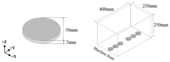
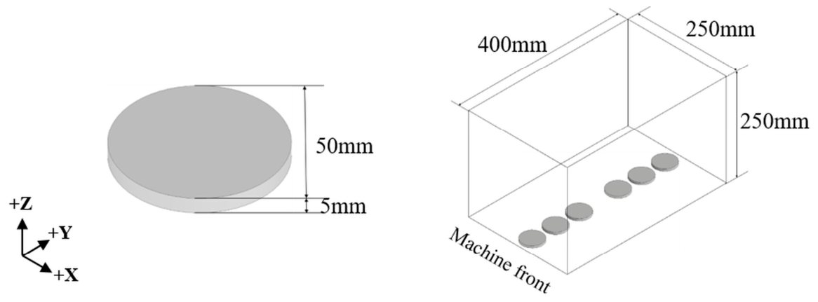
In this study, gas-atomized STS316L powder was used as the feedstock material for the BJT process. The powder morphology was examined using a field-emission scanning electron microscope (FE-SEM, Sirion 400, FEI Company, Hillsboros, OR, USA), and the particle size distribution was summarized in Table 1. In addition, the packing characteristics and flowability of the powder were evaluated in terms of apparent density, tap density, Hausner ratio, and Hall flow rate, with the corresponding results presented in Table 2. Specimens for wear testing were fabricated in the form of disc-shaped samples with a diameter of 50 mm and a thickness of 5 mm, as illustrated in Figure 1. To account for the anisotropy inherent to the BJT process, the specimens were oriented in the build chamber such that the build direction was aligned with the Y-axis. Fabrication was carried out using a commercial binder jetting system (M-Flex, ExOne, North Huntingdon, PA, USA), involving repeated cycles of powder recoating and leveling, selective deposition of a liquid binder (BA005, ExOne, North Huntingdon, PA, USA), infrared (IR) curing, and stepwise lowering of the build platform. To ensure uniform powder spreading, the recoating process was conducted at an oscillator speed of 2000 rpm and a recoating speed of 150 mm/s. The input parameters and additional processing conditions employed in this study are summarized in Table 3. After printing, the green bodies embedded in the powder bed were thermally cured in an oven (OF-LBV-293L, JEIO TECH, Daejeon, Republic of Korea) at 200 °C for 10 h. Following curing, the green bodies were removed from the powder bed, and the surrounding unbound powder was removed by depowdering. The specimens were then placed in a vacuum-capable furnace (TNS VACUUM, Yongin, Republic of Korea). The furnace chamber was evacuated to 1.0 × 10⁻² Torr and subsequently backfilled with Ar, after which thermal debinding and sintering were conducted under an Ar atmosphere. Thermal debinding was incorporated into the heating schedule by applying a heating rate of 1 °C/min between 350 and 450 °C. The specimens were subsequently held at 800 °C for 1 h. The temperature was increased at 5 °C/min from 800 to 1000 °C and at 2 °C/min from 1000 °C to the selected sintering temperature. The specimens were held at 1100, 1200, or 1300 °C for 3 h and then furnace-cooled. Based on the sintering temperature, the specimens were designated as #1 (1100 °C), #2 (1200 °C), and #3 (1300 °C), respectively.
Table 1.
Characteristics of the STS316L powder.
Table 2.
Packing density and flowability of the STS316L powder.
Figure 1.
Isometric view of the test model: Disc model for pin-on-disc wear test.
Table 3.
Input parameters and values for the binder jetting additive manufacturing process.
2.2. Cu Infiltration Process for Cu/STS316L Composite Specimens
The composite specimens were fabricated by placing Cu in foil form on top of the STS316L disc specimens (#1, #2, and #3) sintered under the conditions described in Section 2.1, followed by a molten Cu infiltration process, in which the specimens were heated to 1100 °C and held for 30 min. During this process, the molten Cu infiltrated into the internal pores of the sintered bodies via capillary-driven infiltration. The amount of Cu used for infiltration was determined based on the porosity of each sintered specimen. The specimens infiltrated with Cu at each sintering temperature were designated as Cu/STS316L composites #i-1, #i-2, and #i-3, corresponding to the sintered specimens #1, #2, and #3, respectively.
2.3. Tribological Test
The wear characteristics of the sintered and composite disc specimens were evaluated under dry conditions using a ball-on-disc method with a tribometer (TRB3, Anton Paar, Graz, Austria). The wear tests were conducted under a single set of conditions, with a track radius of 7 mm, an applied normal load of 10 N, a linear sliding speed of 0.1 m/s, and a total sliding distance of 400 m. A SUJ2 steel ball with a diameter of 6 mm was used as the counterface material. The wear-test surfaces of the disc specimens were tested without additional grinding or polishing after sintering or Cu infiltration. No separate mechanical treatment was performed to remove residual surface Cu after infiltration. Before wear testing, all specimens were ultrasonically cleaned in acetone and thoroughly dried. One wear test was conducted for each specimen condition (n = 1). Accordingly, each Coefficient of friction (COF) curve represents an individual test.
2.4. Physical and Microstructural Characterization
The densities of the sintered bodies and composite specimens were measured using the Archimedes method, and the relative density was calculated as the percentage of the measured density to the theoretical density. The density percentages were estimated by normalizing the measured bulk densities to the theoretical density of STS316L, which was assumed to be 8.0 g/cm3. Hardness measurements were performed using a micro-Vickers hardness tester (HMV-2TE, Shimadzu, Kyoto, Japan) under an applied load of 0.1 N with a dwell time of 10 s. For each specimen, five measurements were taken and averaged.
Microstructural observations after the Cu infiltration process were conducted using a field-emission scanning electron microscope (FE-SEM, Sirion 400, FEI Company, Hillsboro, OR, USA). Specimens for microstructural analysis were mechanically polished and subsequently etched using an etchant composed of HCl and HNO3 in a volume ratio of 3:1 (HCl: HNO3). After the wear tests, the morphology and composition of wear tracks and wear debris were examined by FE-SEM coupled with energy-dispersive X-ray spectroscopy (EDS). The three-dimensional profiles of the wear tracks and the maximum wear depth were measured at three different locations using a confocal laser scanning microscope (VK-X200K, Keyence, Osaka, Japan), and the average values were reported. Phase analysis was carried out using X-ray diffraction (X’Pert Pro, PANalytical, Almelo, The Netherlands). Cross-sectional microstructures of the wear tracks and material transfer behavior were investigated by preparing specimens using a focused ion beam (FIB, NOVA-600, FEI Company, Hillsboro, OR, USA), followed by observation with a transmission electron microscope (TEM, TECNAI G2 ST-F20, FEI Company, Hillsboro, OR, USA).
3. Results and Discussion
3.1. Phase and Microstructural Characteristics of Sintered STS316L and Cu/STS316L Composites
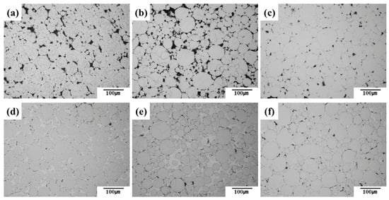
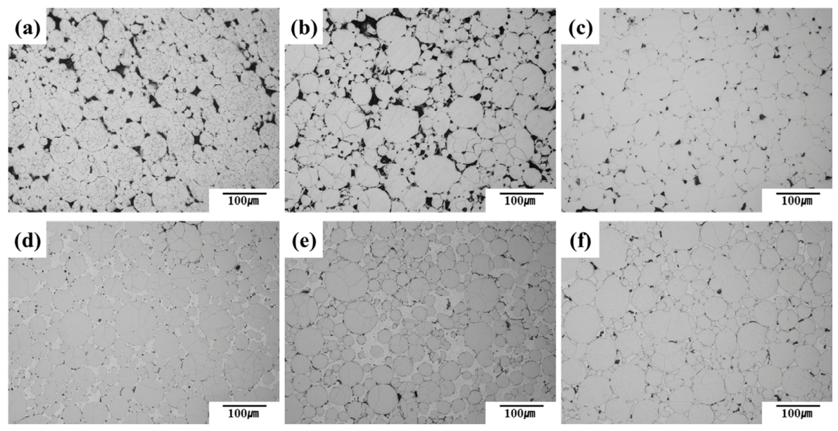
Figure 2 shows FE-SEM images of the surface microstructures of the sintered STS316L specimens (#1–#3) and Cu/STS316L composite specimens (#i-1–#i-3). In the sintered specimens (Figure 2a–c), increasing the sintering temperature from 1100 to 1300 °C gradually reduced the number and size of pores along the particle boundaries while promoting interparticle neck growth. The specimen sintered at 1100 °C (#1) contained numerous irregular pores with sharp edges, whereas the specimen sintered at 1300 °C (#3) exhibited smaller and more spherical pores. These changes can be attributed to enhanced atomic diffusion and progressive neck growth at higher sintering temperatures, indicating an advanced stage of densification. Because irregular pores with sharp edges can act as stress concentrators and potential crack-initiation sites, their transformation into smaller and more spherical pores may reduce localized stress concentration and improve the stability of the mechanical properties [13].
Figure 2.
FE-SEM BSE images of top surface of the STS316L sintered body and Cu/STS316L composite specimens: (a) #1, (b) #2, (c) #3, (d) #i-1, (e) #i-2 and (f) #i-3.
After Cu infiltration, the composite specimens (Figure 2d–f) exhibited a pronounced reduction in both the size and number of pores compared with the corresponding sintered specimens. Bright metallic Cu phases were primarily observed in regions corresponding to the residual pores of the STS316L matrix, indicating that molten Cu penetrated the interconnected pore network through capillary action. Cu was distributed along the fine pores of the STS316L matrix, and its distribution became increasingly homogeneous as the preceding sintering temperature increased. This result suggests that the evolution of the pore network during sintering affected the infiltration pathways and the subsequent distribution of Cu.
The FE-SEM EDS mapping results presented in Figure 3 further clarify the distribution of Cu within the composite specimens. Fe was uniformly distributed throughout the STS316L matrix, whereas Cu was continuously distributed along the pore regions. The composite produced using the specimen sintered at 1300 °C prior to infiltration (Figure 3c) exhibited the most homogeneous Cu distribution. The refined and more uniformly distributed pore network formed at this temperature appears to have provided effective capillary pathways for molten Cu. In contrast, partially uninfiltrated regions were observed in the composite produced from the specimen sintered at 1100 °C (Figure 3a). These regions may be associated with the relatively large and irregular pores remaining after low-temperature sintering. Because capillary pressure decreases with increasing pore radius, these larger pores may provide a weaker driving force for infiltration, resulting in incomplete filling in some regions.
Figure 3.
FE-SEM Mapping images of top surface of the Cu/STS316L composite specimens: (a) #i-1, (b) #i-2, (c) #i-3. The inset SEM images correspond to the regions analyzed by EDS elemental mapping and are presented at the same size as the corresponding Fe and Cu maps.
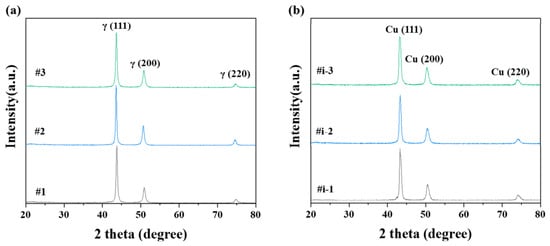
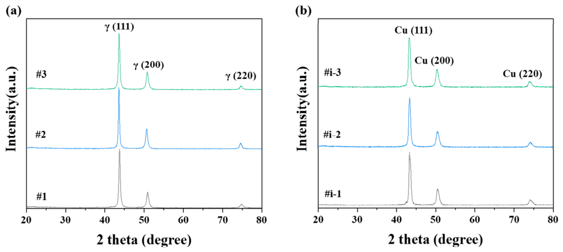
Figure 4 presents the XRD patterns of the sintered STS316L and Cu/STS316L composite specimens. For the sintered specimens (Figure 4a), only γ-austenite peaks corresponding to the (111), (200), and (220) planes were detected under all sintering-temperature conditions, with no detectable δ-ferrite peaks. This result indicates that the STS316L matrix retained its γ-austenitic structure throughout the investigated sintering-temperature range of 1100–1300 °C. The composite specimens (Figure 4b) exhibited additional Cu peaks corresponding to the (111), (200), and (220) planes together with the γ-austenite peaks. The distinct FCC Cu peaks and the absence of additional peaks associated with Cu–STS316L intermetallic compounds suggest that Cu remained predominantly as an independent metallic phase within the residual pores. Accordingly, the reduction in porosity and densification of the Cu/STS316L composites occurred primarily through the physical filling of the interconnected pore network by molten Cu rather than through the formation of detectable intermetallic compounds.
Figure 4.
X-ray diffraction patterns: (a) STS316L sintered body and (b) Cu/STS316L composite specimens.
3.2. Effect of Cu Infiltration on Relative Density and Hardness
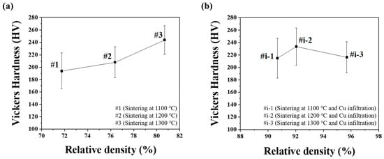
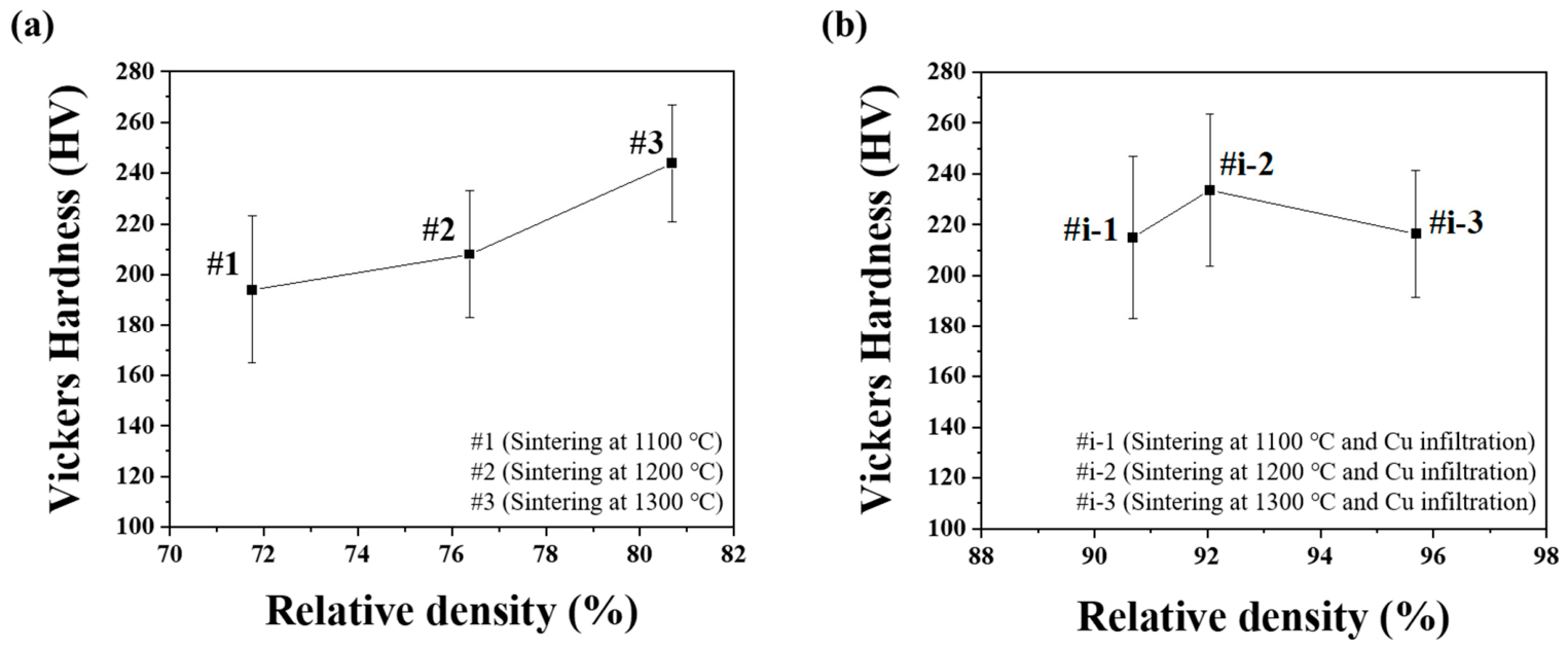
Figure 5 summarizes the changes in relative density and hardness of the sintered STS316L and Cu/STS316L composite specimens as a function of sintering temperature. For the sintered STS316L specimens (Figure 5a), the relative densities of specimens #1, #2, and #3 were 72.75%, 76.38%, and 80.69%, respectively, while their corresponding hardness values were 194, 208, and 243.8 HV. The density values were estimated by normalizing the Archimedes bulk densities to the theoretical density of STS316L (8.0 g/cm3). Thus, both relative density and hardness increased as the sintering temperature increased from 1100 to 1300 °C. The simultaneous increases in relative density and hardness can be attributed to the progressive densification of the STS316L specimens at higher sintering temperatures. The reduction in residual porosity increases the effective load-bearing area and decreases the number of pore-related stress-concentration sites, thereby improving resistance to localized indentation. Similar relationships among sintering temperature, densification, and mechanical properties have been reported for materials fabricated by conventional powder metallurgy and binder jetting [13,14,15].
Figure 5.
Relationship between relative density and Vickers hardness: (a) STS316L sintered body and (b) Cu/STS316L composite specimens.
For the Cu/STS316L composite specimens (Figure 5b), the relative densities of specimens #i-1, #i-2, and #i-3 were 90.68%, 92.04%, and 95.69%, respectively. These values were higher than those of the corresponding sintered STS316L specimens under all sintering-temperature conditions, demonstrating that Cu infiltration substantially increased the relative density by filling the residual pores in the sintered STS316L skeleton.
In contrast to the relative density, the hardness of the composite specimens did not increase monotonically with sintering temperature. The hardness values of specimens #i-1, #i-2, and #i-3 were 215, 233.6, and 216.4 HV, respectively. The highest hardness among the composite specimens was measured for specimen #i-2, whereas the highest overall hardness was obtained for the sintered STS316L specimen #3. This behavior can be attributed to the lower intrinsic hardness of Cu compared with that of the sintered STS316L matrix. Consequently, the measured hardness of the composites was affected by the local proportions of Cu, STS316L, and residual pores within the indentation region.
In particular, the decrease in hardness from specimen #i-2 to specimen #i-3, despite the increase in relative density, indicates that the hardness of the composites was governed not only by residual porosity but also by the spatial distribution and local volume fraction of infiltrated Cu. The relatively large variations in the hardness values of the composite specimens may likewise result from variations in Cu distribution and residual porosity among the indentation locations. Therefore, although Cu infiltration effectively enhanced the relative density of the Cu/STS316L composites, increased densification alone did not necessarily result in increased hardness.
Because the actual Cu uptake was not measured, the composition-based theoretical densities of the Cu/STS316L composites could not be determined. Therefore, the reported density percentages should be interpreted as normalized comparative values referenced to the theoretical density of STS316L, rather than absolute composite relative densities corrected for the actual Cu content.
3.3. Tribological Behavior and Wear Track Characteristics
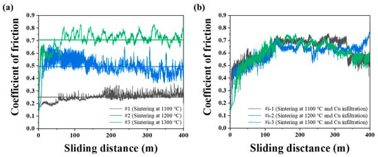
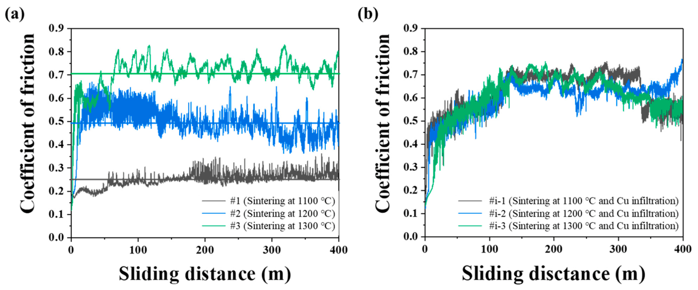
Figure 6 shows the coefficient-of-friction curves of the sintered STS316L and Cu/STS316L composite specimens. For the sintered specimens (Figure 6a), the average coefficient of friction increased with increasing sintering temperature. Specimen #1 maintained a relatively low and stable coefficient of friction of approximately 0.25–0.30 throughout the sliding test, without a clearly distinguishable running-in stage. This behavior suggests that the contact conditions remained comparatively stable during sliding. In contrast, specimens #2 and #3 exhibited an initial increase in the coefficient of friction followed by fluctuations during the steady-state regime, indicating progressive changes at the contact interface. In particular, specimen #3 showed a sharp increase in the coefficient of friction to approximately 0.8 after a sliding distance of approximately 70–80 m. This abrupt increase suggests a change in the wear-surface condition or dominant wear process during sliding. However, because the coefficient of friction alone cannot be used to determine wear loss, these results should be interpreted together with the wear-track dimensions and surface morphologies.
Figure 6.
Variations in coefficient of friction during pin-on-disc wear test: (a) STS316L sintered body and (b) Cu/STS316L composite specimens.
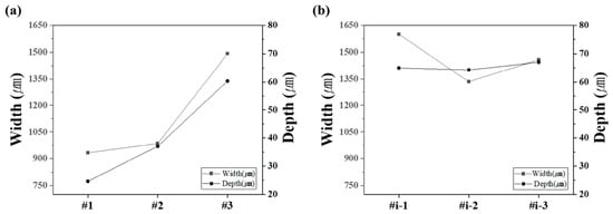
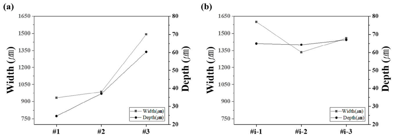
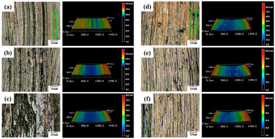
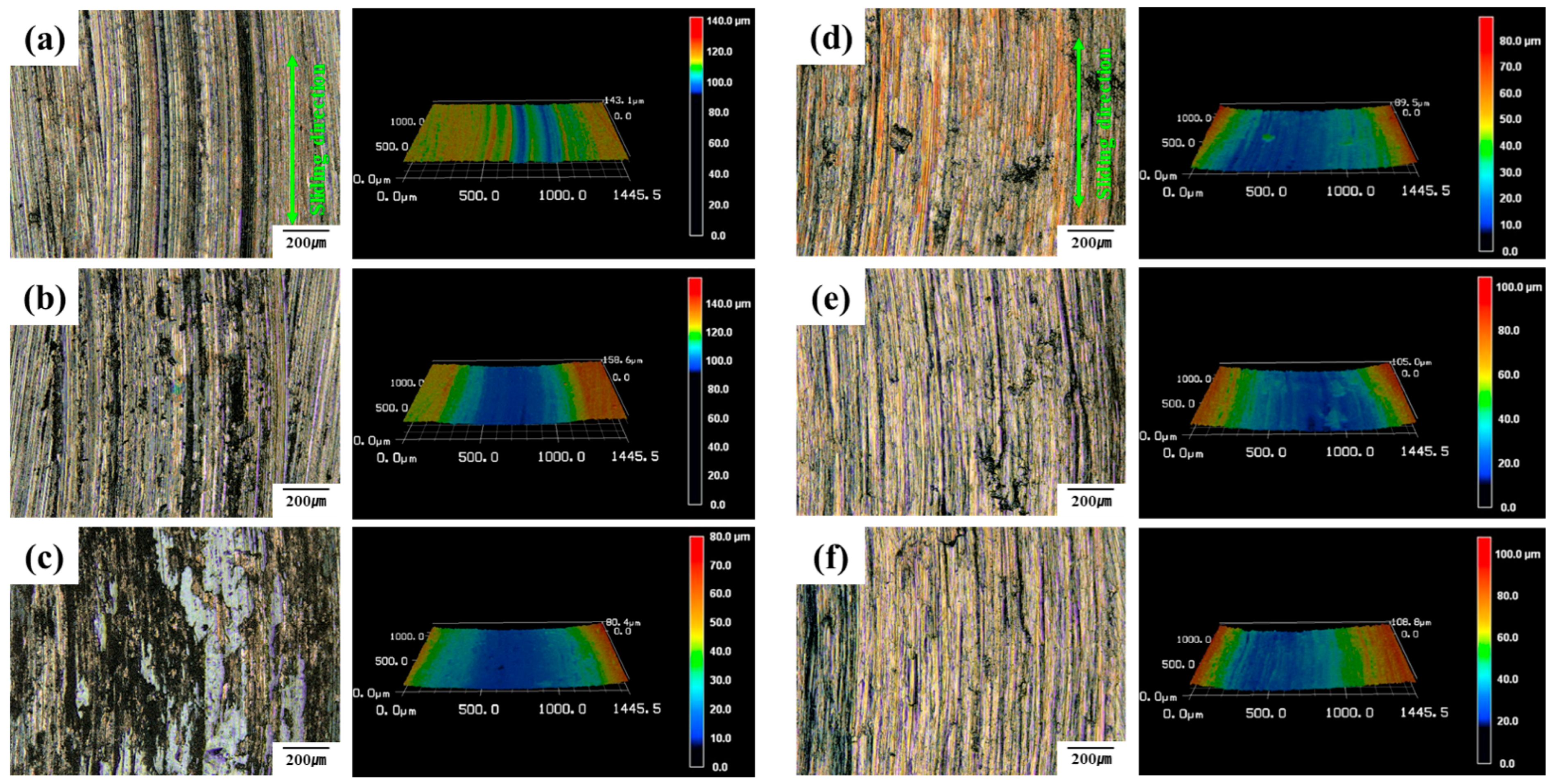
The wear-track dimensions measured using FE-SEM and confocal laser scanning microscopy (CLSM) are summarized in Figure 7. For the sintered specimens (Figure 7a), the wear widths of specimens #1, #2, and #3 were 932.8, 985.1, and 1492.0 μm, respectively, while the corresponding maximum wear depths were 24.7, 37.0, and 60.3 μm. Both wear width and maximum depth increased with increasing sintering temperature, despite the concurrent increase in hardness. These results demonstrate that hardness was not the sole factor governing wear behavior under the present test conditions.
Figure 7.
Wear width and depth of the wear scar: (a) STS316L sintered body and (b) Cu/STS316L composite specimens.
Dubrujeaud et al. reported that pores in iron-based sintered materials can trap detached wear debris and that pore morphology and size strongly influence the resulting wear behavior [16]. Based on this mechanism, the relatively large pores in specimens #1 and #2 may have acted as reservoirs for detached debris, thereby limiting the continued circulation of abrasive particles at the contact interface. In contrast, the finer and less numerous pores in specimen #3 may have provided less capacity for debris accommodation, increasing the interaction between the wear debris and sliding surfaces. This difference may explain why specimen #3 exhibited greater wear-track dimensions despite having the highest hardness among the sintered specimens.
The three-dimensional CLSM wear-track profiles shown in Figure 8 provide further evidence of differences in the wear behavior of the sintered specimens. Specimens #1 and #2 (Figure 8a,b) exhibited relatively uniform worn surfaces with moderate roughness and shallow micro-grooves. In contrast, specimen #3 (Figure 8c) exhibited discontinuous and heterogeneous surface layers within the wear track. These layers may have formed through the accumulation, compaction, oxidation, and subsequent delamination of fine wear debris. This interpretation is consistent with the sharp increase in the coefficient of friction and the greater wear-track width and depth observed for specimen #3. Nevertheless, detailed compositional and cross-sectional analyses would be required to determine the specific nature and formation mechanism of these surface layers.
Figure 8.
CLSM-3D surface profiles: (a) #1, (b) #2, (c) #3, (d) #i-1, (e) #i-2 and (f) #i-3.
The Cu/STS316L composite specimens exhibited similar friction behavior regardless of the preceding sintering temperature, as shown in Figure 6b. Their coefficients of friction initially increased from approximately 0.5 until a sliding distance of approximately 120 m and subsequently fluctuated within the range of approximately 0.65–0.75. The average coefficient of friction was approximately 0.6 for all composite specimens. The gradual increase during the running-in stage may be related to the development of adhesive contact and material transfer at the sliding interface. After a relatively stable transfer layer or tribological contact condition was established, the coefficients of friction remained within a similar range for all composite specimens. Because the wear-test surfaces were not additionally ground or polished and the initial surface roughness was not measured, differences in the as-processed surface topography may also have contributed to the running-in behavior and COF. Accordingly, the effects of density, pore structure, and Cu infiltration were interpreted together with the observed wear-track and subsurface morphologies rather than from the COF curves alone.
For the composite specimens (Figure 7b), the wear widths of specimens #i-1, #i-2, and #i-3 were 1599.3, 1355.3, and 1457.7 μm, respectively. Their maximum wear depths ranged from 64.3 to 67.0 μm, showing relatively small differences among the three conditions. Specimen #i-2 exhibited the smallest wear width among the composite specimens. However, because the three composites exhibited similar maximum wear depths and coefficients of friction, the smaller wear width of specimen #i-2 should not be interpreted solely as evidence of a change in the dominant wear mechanism.
The three-dimensional CLSM profiles in Figure 8 show that the composite specimens had comparatively smooth wear tracks with broadly similar surface morphologies under all processing conditions. The similar coefficient-of-friction curves, nearly constant maximum wear depths, and comparable wear-track morphologies indicate that the infiltrated Cu phase exerted a stronger influence on the tribological behavior than the initial sintering-temperature-dependent differences in the STS316L skeleton. Overall, the distinct friction behavior, wear-track dimensions, and surface morphologies of the sintered and Cu-infiltrated specimens demonstrate that pore structure and Cu distribution played important roles in governing their respective wear responses.
Two limitations should be considered when interpreting these results. First, only one wear test was conducted for each specimen condition (n = 1). Accordingly, each COF curve represents an individual test, and the reported mean COF is a time-averaged value calculated over the steady-state region of that test (150–400 m), rather than an average of independent replicate tests. The CLSM measurements obtained at three representative positions along each wear track characterize spatial variation within an individual track and do not constitute independent experimental replicates. Therefore, the reproducibility and statistical significance of the differences in COF and wear-track dimensions could not be evaluated. Second, the wear-track width and maximum depth are linear measures of wear-track geometry rather than measures of the total volume of material loss. Because volumetric analysis was not included in the original CLSM measurement procedure, wear volume and specific wear rate were not determined. The observed differences should therefore be interpreted as comparative trends in wear-track severity under the present test conditions rather than as a complete quantitative or statistically validated comparison of wear rates.
3.4. Morphology of Worn Surface and Wear Mechanisms
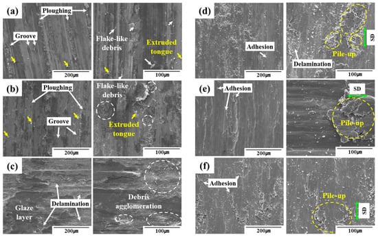
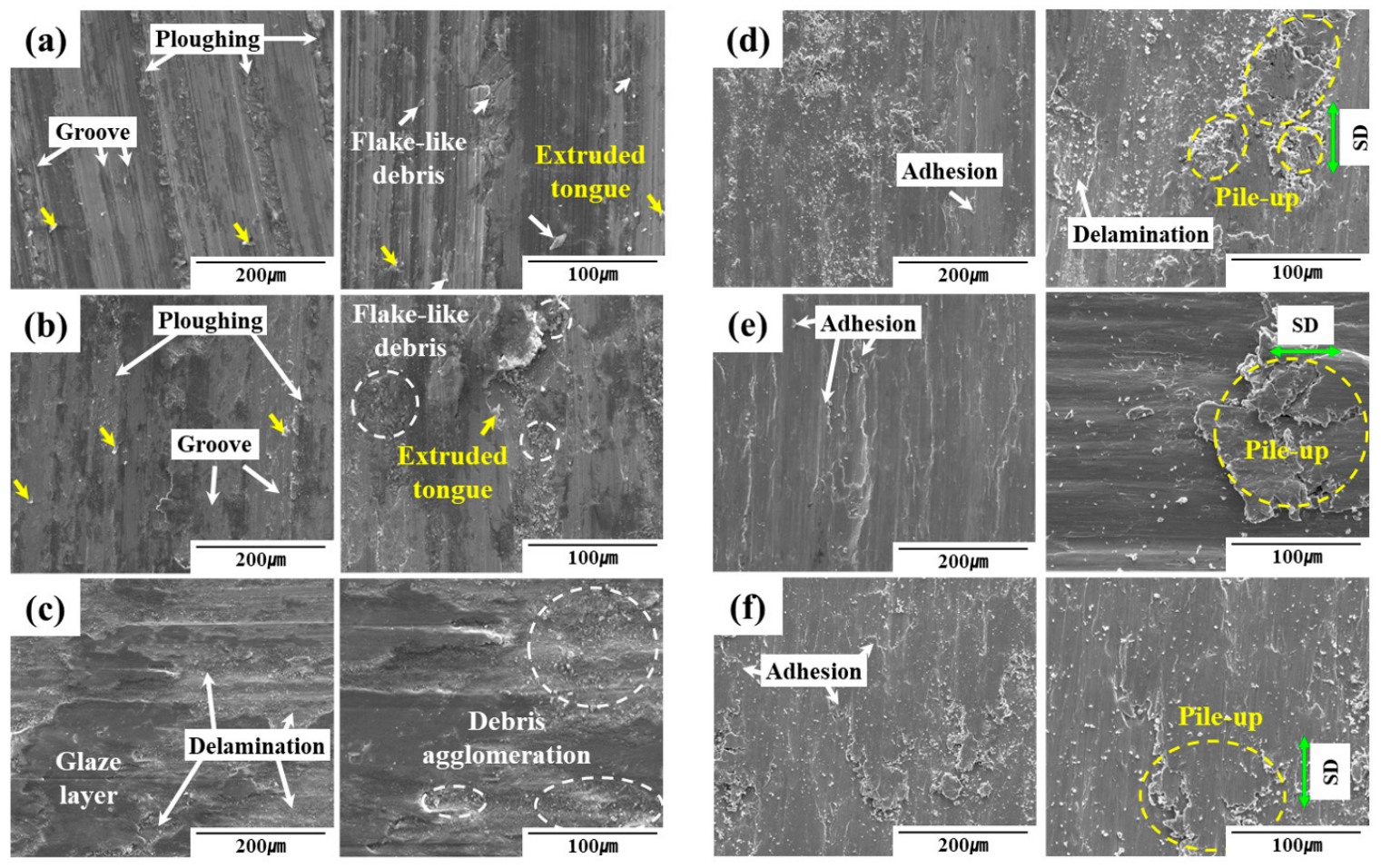
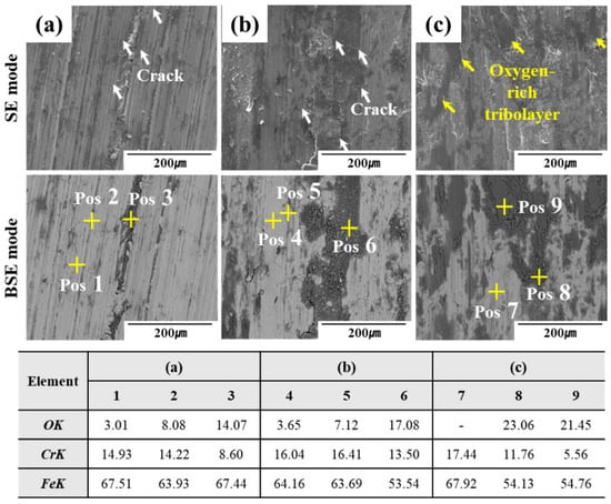
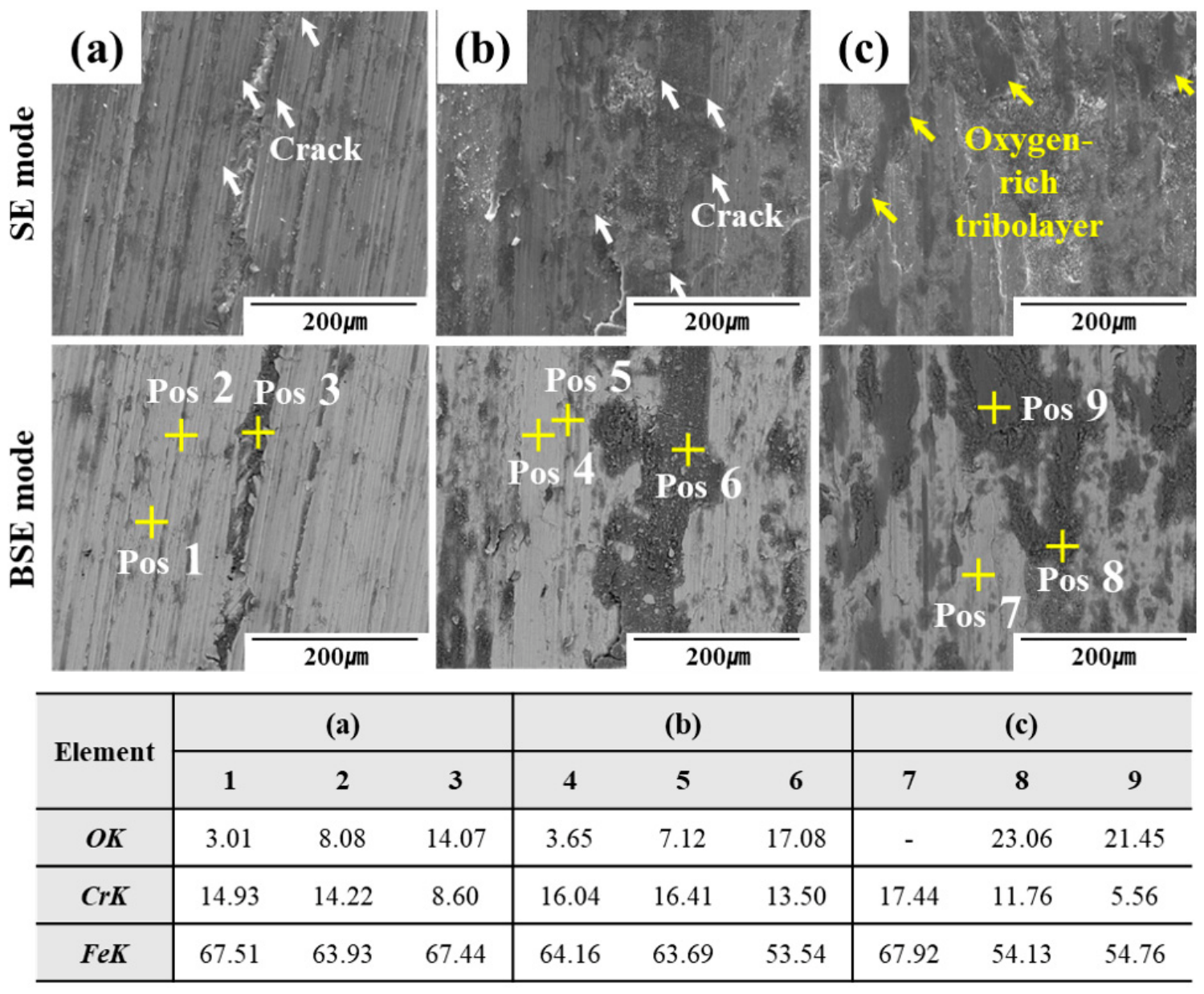
The worn surfaces and subsurface regions of the sintered STS316L and Cu/STS316L composite specimens were examined to identify the morphological and compositional changes produced during sliding and to determine their dominant wear mechanisms. As shown in Figure 9a,b, specimens #1 and #2 exhibited micro-grooves and ploughing features oriented along the sliding direction. Wear debris of various sizes was distributed within and around these regions, while plate-like debris and locally extruded tongue-like features were also observed. The micro-grooves, ploughing marks, and loose debris indicate that abrasive wear contributed substantially to the wear behavior of specimens #1 and #2. Because these specimens retained relatively high porosity, detached particles could enter the contact interface and act as third-body abrasives. Simchi et al. reported that high porosity reduces interparticle bonding strength and increases the likelihood of crack initiation in sintered materials [17]. Accordingly, the plate-like debris and extruded tongue-like features may have resulted from repeated deformation and local fracture near weak particle boundaries and pore edges during cyclic sliding.
Figure 9.
FE-SEM images of wear scar: (a) #1, (b) #2, (c) #3, (d) #i-1, (e) #i-2 and (f) #i-3.
In contrast, specimen #3 exhibited agglomerated fine wear debris within the delaminated regions, resulting in the formation of discontinuous and heterogeneous surface layers (Figure 9c). These layers were irregularly distributed across the wear track rather than forming a continuous surface film. Cui et al. reported that compacted debris layers can act as protective tribolayers by limiting direct contact between opposing surfaces [10]. In the present study, however, the layers formed on specimen #3 were discontinuous and accompanied by extensive delamination. Therefore, they were unlikely to remain sufficiently stable to provide sustained surface protection. The repeated formation and removal of these heterogeneous layers are consistent with the relatively high coefficient of friction and large wear-track dimensions measured for specimen #3.
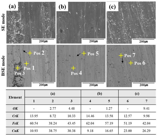
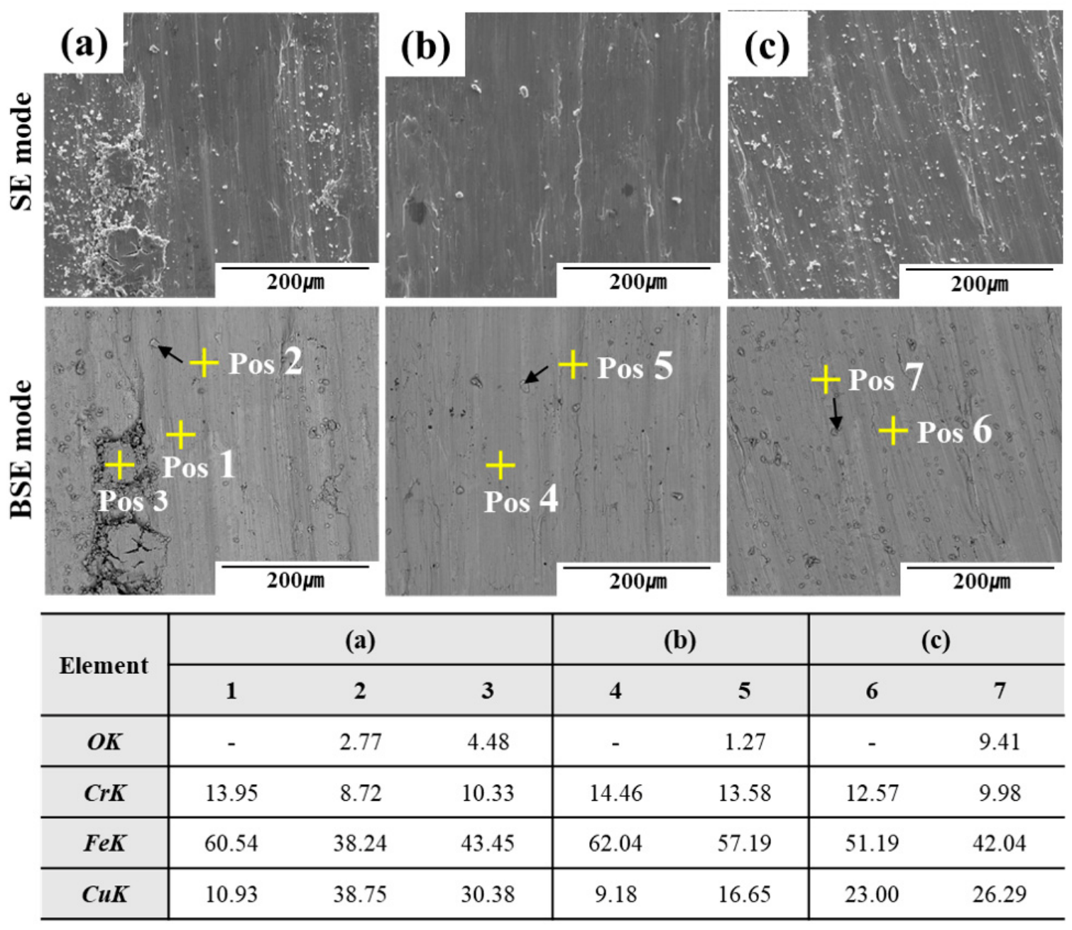
The EDS results for selected worn-surface regions of the sintered specimens are summarized in Figure 10. Oxygen was detected in the micro-groove regions (Pos 2 and 5) and the ploughed regions (Pos 3 and 6). In specimen #3, oxygen was also detected in the delaminated region at Pos 8 and the heterogeneous surface layer at Pos 9. These regions exhibited higher oxygen contents than the analyzed worn regions of specimens #1 and #2, indicating that oxidation became more pronounced in specimen #3.
Figure 10.
FE-SEM images of wear scar and EDS point results of the STS316L sintered body specimens: (a) #1, (b) #2 and (c) #3. (SE and BSE denote secondary-electron and backscattered-electron images, respectively. OK, CrK, and FeK represent the EDS elemental maps obtained using the K-series characteristic X-ray signals of oxygen, chromium, and iron, respectively, while “Pos” indicates the analysis position.)
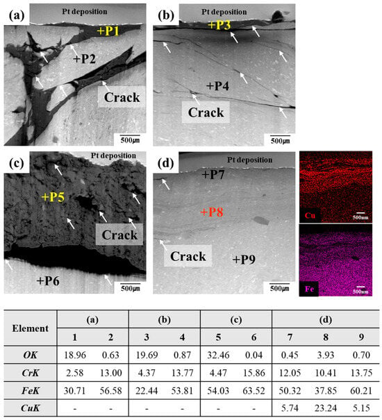
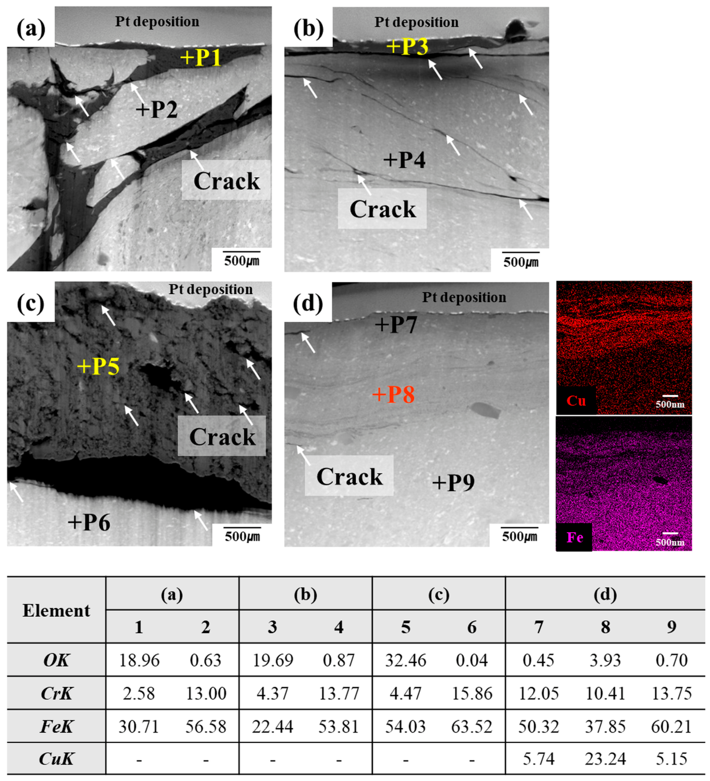
Cross-sectional TEM and EDS analyses were conducted to characterize the oxygen-rich tribolayers and subsurface structures beneath the wear tracks. As shown in Figure 11a–c, thin oxide films with thicknesses of several tens of nanometers were observed at P1 and P3 (Position 1 and 3) in specimens #1 and #2, respectively. In comparison, specimen #3 exhibited an oxygen-rich tribolayer approximately 2.5 μm thick at P5. Oxide-layer growth during sliding can be promoted by frictional heating and repeated exposure of fine metallic debris to the surrounding atmosphere [18,19,20]. Therefore, the higher oxygen concentrations in the heterogeneous and delaminated regions of specimen #3, together with the thick oxygen-rich tribolayer identified by TEM, support the formation of an oxide-rich mechanically mixed layer.
Figure 11.
HAADF-STEM images of cross-sectional microstructure and EDS point results: (a) #1, (b) #2, (c) #3 (d) #i-2. (P1, P2, and P8 indicate the EDS point-analysis locations. The different label colors were used solely to improve visibility against the image background and have no scientific significance).
Subsurface cracks were observed beneath the thick oxygen-rich tribolayer of specimen #3 and propagated approximately parallel to the worn surface. Large pores were also present in the subsurface region below the oxygen-rich tribolayer. These observations suggest that repeated contact loading caused crack initiation near the oxide–matrix interface. Crack propagation parallel to the worn surface could promote delamination of the oxygen-rich tribolayer and expose fresh matrix material. The pores beneath the oxygen-rich tribolayer may also have acted as local stress concentrators and facilitated subsurface crack initiation. Repeated cycles of oxide formation, cracking, and delamination can therefore account for the abrupt increase in friction and severe wear observed in specimen #3.
The Cu/STS316L composite specimens shown in Figure 9d–f exhibited relatively smooth worn surfaces under all processing conditions. Adhesive features and pile-up structures were commonly observed along the wear tracks, and the overall worn-surface morphologies were similar among the three composite specimens. These characteristics indicate that adhesive wear and plastic deformation dominated their contact response. Pile-up formation is commonly associated with repeated plastic flow under high contact stresses, particularly in ductile surface regions [21].
For the composite specimens, the EDS results in Figure 12 showed that Cu was distributed throughout the wear tracks. The wear debris at Pos 2, 5, and 7 and the pile-up region at Pos 3 contained Fe, Cu, and O, confirming the presence of Fe- and Cu-containing oxides within the debris and plastically deformed regions. The detection of Cu throughout the wear tracks also indicates that the infiltrated Cu was displaced from the pores and redistributed across the sliding surface during repeated contact.
Figure 12.
FE-SEM images of wear scar and EDS point results of the Cu/STS316L composite specimens: (a) #i-1, (b) #i-2 and (c) #i-3.
The cross-section of the composite specimen shown in Figure 11d exhibited a comparatively uniform and smooth surface. The P8 region contained a relatively high concentration of Cu and formed a thin Cu-rich layer along the worn surface. This layer supports the occurrence of Cu transfer and surface smearing during sliding. Owing to its ductility and relatively low shear strength, Cu may facilitate interfacial shear and contribute to the formation of a smoother worn surface [22,23]. However, the present results do not demonstrate that Cu infiltration reduced the coefficient of friction relative to the sintered specimens under all conditions. Therefore, Cu is more appropriately interpreted as modifying the dominant wear mechanism through plastic flow and material transfer rather than acting solely as a self-lubricating phase.
No oxygen-rich tribolayer comparable in thickness to that observed in specimen #3 was identified in the composite specimen. Although the presence of Fe, Cu, and O in the debris and pile-up regions indicates that mechanical mixing and partial oxidation occurred during continued sliding, repeated Cu transfer and plastic deformation likely disrupted the development of a continuous oxygen-rich tribolayer. This interpretation is consistent with the absence of a thick oxide film and the similar friction behavior observed among the three composite specimens. Overall, the dominant wear behavior of the sintered specimens changed from predominantly abrasive and adhesive wear at lower sintering temperatures to pronounced oxidative delamination at 1300 °C, whereas the Cu/STS316L composites were governed mainly by adhesive wear associated with Cu transfer and plastic deformation.
3.5. Microstructure of the Worn Ball Surface
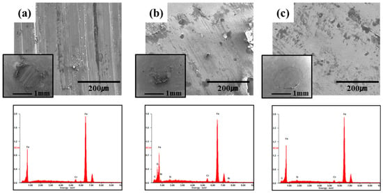
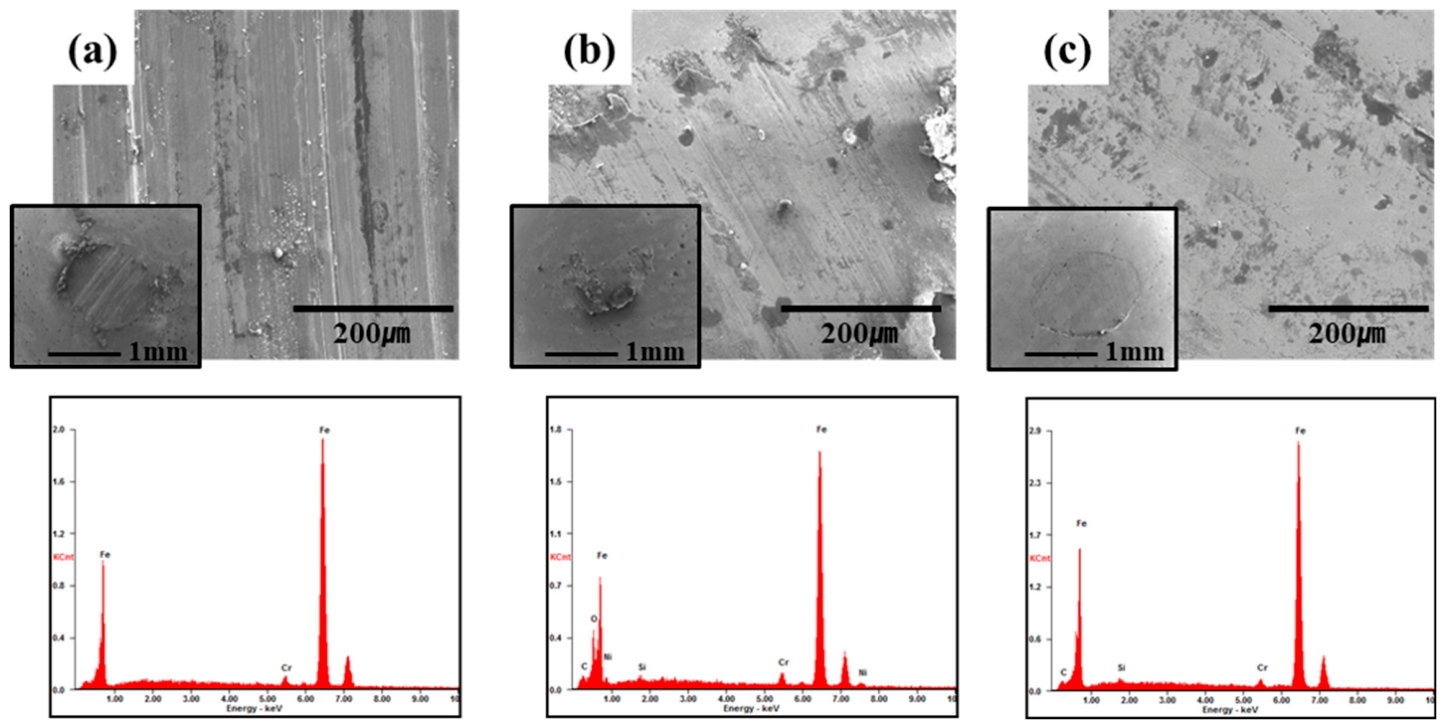
The worn surfaces of the counterface balls were examined by SEM to compare their surface features with those of the corresponding STS316L specimens and to clarify the interactions occurring at the sliding interfaces. Figure 13 shows the surface morphologies of the counterface balls paired with the sintered STS316L specimens. Fine grooves were observed on the counterface balls corresponding to specimens #1 and #2, indicating that abrasive interactions occurred on both sides of the sliding interface. In particular, loose wear debris was observed on the counterface ball paired with specimen #1. This observation supports the occurrence of three-body abrasion, in which detached particles circulate between the two contacting surfaces [24], and is consistent with the micro-grooves and wear debris observed on the corresponding STS316L wear track.
Figure 13.
FE-SEM images and EDS results of the wear scar of the counterface ball corresponding to the STS316L sintered body specimens: (a) #1, (b) #2 and (c) #3.
Adhesive features were also observed near the edges of the wear tracks on the counterface balls paired with specimens #1 and #2. These features indicate that some of the material detached from the specimens was transferred to and accumulated on the counterface surfaces. In addition, oxygen-containing regions were detected on the counterface ball corresponding to specimen #2, suggesting that oxidized wear debris adhered to the ball surface. These relatively hard oxidized particles may have participated in the repeated scratching and ploughing of the mating specimen, contributing to the greater material loss of specimen #2 compared with specimen #1.
In contrast, the counterface ball paired with specimen #3 exhibited a comparatively flat and smooth worn surface, without distinct micro-grooves, accumulated wear debris, or delaminated regions. This morphology indicates that the interfacial interaction associated with specimen #3 differed from those associated with specimens #1 and #2. The thick oxide-rich layer formed on specimen #3 may have acted as a comparatively hard sliding surface against the counterface ball. Repeated contact with this oxygen-rich tribolayer may have progressively flattened the ball surface while promoting cutting or delamination on the specimen side.
The ball-on-disc configuration initially produces a small contact area and high localized contact stresses. As the wear scar on the counterface ball expands during sliding, the real contact area increases, potentially altering the subsequent friction and wear behavior. Therefore, the smooth worn surface of the ball paired with specimen #3 should be interpreted together with the thick oxygen-rich tribolayer, subsurface cracks, and extensive delamination observed on the corresponding specimen rather than as direct evidence of mild wear throughout the sliding system.
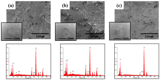
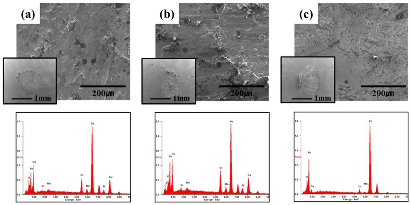
Figure 14 shows SEM images of the counterface balls paired with the Cu/STS316L composite specimens. These balls exhibited smooth worn regions accompanied by adhesive features. EDS analysis detected Cu on the counterface surfaces in addition to the constituent elements of the original ball material, confirming that Cu was transferred from the composite specimens to the balls during sliding.
Figure 14.
FE-SEM images and EDS results of the wear scar of the counterface ball corresponding to the Cu/STS316L composite specimens: (a) #i-1, (b) #i-2 and (c) #i-3.
Su et al. reported that Cu may soften under frictional heating and transfer to a steel counterface, changing the contact condition from Cu–steel interaction toward contact between Cu-rich surface regions [21]. Such transfer can increase adhesion between the sliding surfaces and is consistent with the relatively high coefficients of friction observed for the composite specimens. The transferred Cu may also have contributed to the formation of smooth worn surfaces through plastic flow and surface smearing.
However, the present results indicate that Cu transfer did not simply reduce friction. Instead, it modified the sliding interface by promoting adhesive contact and repeated material exchange between the specimens and counterface balls. Therefore, the wear behavior of the Cu/STS316L composites was governed primarily by adhesive wear associated with Cu transfer rather than by a purely self-lubricating effect.
4. Conclusions
The following conclusions were drawn from a comparative analysis of the microstructural evolution, wear behavior, and wear mechanisms of STS316L sintered bodies fabricated by the BJT process and Cu-infiltrated composites as a function of sintering temperature:
- As the sintering temperature of the STS316L sintered bodies increased from 1100 to 1300 °C, the number and size of pores decreased while interparticle neck growth was promoted, resulting in increases in relative density and hardness. In contrast, the composite specimens exhibited higher relative densities than the corresponding sintered bodies under all conditions due to capillary-driven infiltration of molten Cu into the internal pores. The infiltrated Cu existed as an independent FCC metallic phase within the pore regions, without the formation of detectable intermetallic compounds.
- The average coefficient of friction of the sintered bodies increased from approximately 0.25 to 0.71 with increasing sintering temperature, accompanied by increases in wear width and depth. In contrast, the composite specimens exhibited similar friction behavior regardless of the preceding sintering temperature, with an average coefficient of friction of approximately 0.6. Their maximum wear depths ranged from 64.3 to 67.0 μm, showing relatively small differences among the three conditions.
- At 1100 and 1200 °C, abrasive and adhesive wear were predominant, and the residual pores affected the accommodation and circulation of wear debris. At 1300 °C, repeated formation, cracking, and delamination of an approximately 2.5 μm thick oxygen-rich tribolayer resulted in pronounced oxidative delamination despite the higher density and hardness.
- For the composite specimens, relatively smooth worn surfaces were formed under all sintering conditions. Surface transfer of Cu and the resulting adhesive wear were identified as the dominant wear mechanism, independent of sintering temperature.
- The wear mechanisms of the counterface balls were consistent with those of the corresponding specimens. For the sintered bodies, abrasive wear and three-body wear were observed depending on sintering temperature, whereas adhesive wear was predominant for the composite specimens.
These findings provide a mechanistic basis for optimizing binder-jetted Cu/STS316L composites for wear-resistant sliding components, particularly journal bearings. The relationships among pore structure, Cu distribution, material transfer, and adhesive wear should be considered when selecting sintering and infiltration conditions. Further application-specific testing under practical loading and lubrication conditions is required to verify their long-term performance as journal-bearing materials.
Author Contributions
Conceptualization, K.-T.K.; methodology, T.K.; validation, K.I.K.; formal analysis, T.K. and M.K.; investigation, T.K., M.K. and K.I.K.; data curation, T.K., M.K. and K.I.K.; writing—original draft preparation, T.K.; writing—review and editing, T.K., M.K. and K.-T.K.; visualization, T.K. and M.K.; supervision, K.-T.K.; project administration, K.-T.K.; funding acquisition, K.-T.K. All authors have read and agreed to the published version of the manuscript.
Funding
This work was supported by the Technology Innovation Program (20024344, Development of AI-based high carbon steel alloy design and sintering-based additive manufacturing technology for 7.0L/Hr-level high-speed production of powertrain components with tensile strength over 1.0GPa in the next-generation mobility) funded by the Ministry of Trade Industry& Energy (MOTIE, Republic of Korea). This study has been conducted with the support of the Korea Institute of Industrial Technology as “Development of High-Performance Composite-Based Sliding Bearings for Advanced Mobility Using Binder Jetting 3D Printing and Pressure-Free Cu Infiltration Process (KITECH UR26090)” & Ministry of Trade, Industry and Energy as “Development of design for additive manufacturing technology and low alloy steel materials with tensile strength 1.0GPa for next-generation components (RS-2023-KT224345)”.
Data Availability Statement
The original contributions presented in this study are included in the article. Further inquiries can be directed to the corresponding author.
Conflicts of Interest
The authors declare no conflicts of interest.
References
- Mostafaei, A.; Elliott, A.M.; Barnes, J.E.; Li, F.; Tan, W.; Cramer, C.L.; Nandwana, P.; Chmielus, M. Binder jet 3D printing—Process parameters, materials, properties, modeling, and challenges. Prog. Mater. Sci. 2021, 119, 100707. [Google Scholar] [CrossRef] [Scilit]
- Guo, N.; Leu, M.C. Additive manufacturing: Technology, applications and research needs. Front. Mech. Eng. 2013, 8, 215–243. [Google Scholar] [CrossRef] [Scilit]
- Shahrubudin, N.; Lee, T.C.; Ramlan, R. An overview on 3D printing technology: Technological, materials, and applications. Procedia Manuf. 2019, 35, 1286–1296. [Google Scholar] [CrossRef] [Scilit]
- Kang, M.C.; Lee, D.H.; Go, G.H. International development trend and technical issues of metal additive manufacturing. J. Weld. Join. 2016, 34, 9–16. [Google Scholar] [CrossRef] [Scilit]
- Chen, L.; Chen, W.; Fu, Z.; Ding, G.; Chen, Z.; Zhu, D. Binder jet 3D printing of 316L stainless steel: Orthogonal printing and sintering process optimization. Adv. Eng. Mater. 2023, 25, 2200641. [Google Scholar] [CrossRef] [Scilit]
- Rios, A.C.; Hryha, E.; Olesky, E.; Halin, P. Sintering anisotropy of binder jetted 316L stainless steel: Part II—Microstructure evolution during sintering. Powder Metall. 2022, 65, 283–295. [Google Scholar] [CrossRef] [Scilit]
- Mostafaei, A.; De Vecchis, P.R.; Nettleship, I.; Chmielus, M. Effect of powder size distribution on densification and microstructural evolution of binder-jet 3D-printed alloy 625. Mater. Des. 2019, 162, 375–383. [Google Scholar] [CrossRef] [Scilit]
- Cordero, Z.C.; Siddel, D.H.; Peter, W.H.; Elliott, A.M. Strengthening of ferrous binder jet 3D printed components through bronze infiltration. Addit. Manuf. 2017, 15, 87–92. [Google Scholar] [CrossRef] [Scilit]
- Wang, L.; Tieu, A.K.; Lu, S.; Jamali, S.; Hai, G.; Zhu, Q.; Nguyen, H.H.; Cui, S. Sliding wear behavior and electrochemical properties of binder jet additively manufactured 316SS/bronze composites in marine environment. Tribol. Int. 2021, 156, 106810. [Google Scholar] [CrossRef] [Scilit]
- Cui, S.; Lu, S.; Tieu, K.; Meenashisundaram, G.K.; Wang, L.; Li, X.; Wei, J.; Li, W. Detailed assessments of tribological properties of binder jetting printed stainless steel and tungsten carbide infiltrated with bronze. Wear 2021, 477, 203788. [Google Scholar] [CrossRef] [Scilit]
- Oh, J.W. Mechanical Properties of Mechanical Parts Enhanced by Molten Infiltration and Reliability Improvement of the Binder Jetting Additive Manufacturing Process. Ph.D. Thesis, Korea University, Seoul, Republic of Korea, 2022. [Google Scholar]
- Jang, J.M. Fabrication of Cu-infiltrated journal bearing by binder jetting additive manufacturing. Crystals 2024, 14, 912. [Google Scholar] [CrossRef] [Scilit]
- Kurgan, N. Effect of porosity and density on the mechanical and microstructural properties of sintered 316L stainless steel implant materials. Mater. Des. 2014, 55, 235–241. [Google Scholar] [CrossRef] [Scilit]
- Tang, Y.; Huang, Z.; Yang, J.; Xie, Y. Enhancing the capillary force of binder-jetting printing Ti6Al4V and mechanical properties under high temperature sintering by mixing fine powder. Metals 2020, 10, 1354. [Google Scholar] [CrossRef] [Scilit]
- Huber, D.; Vogel, L.; Fischer, A. The effects of sintering temperature and hold time on densification, mechanical properties and microstructural characteristics of binder jet 3D printed 17-4 PH stainless steel. Addit. Manuf. 2021, 46, 102114. [Google Scholar] [CrossRef] [Scilit]
- Dubrujeaud, B.; Vardavoulias, M.; Jeandin, M. The role of porosity in the dry sliding wear of a sintered ferrous alloy. Wear 1994, 174, 155–161. [Google Scholar] [CrossRef] [Scilit]
- Simchi, A.; Danninger, H. Effects of porosity on delamination wear behaviour of sintered plain iron. Powder Metall. 2004, 47, 73–80. [Google Scholar] [CrossRef] [Scilit]
- Kato, K.; Adachi, K. Wear mechanisms. In Modern Tribology Handbook: Volume One: Principles of Tribology; CRC Press: Boca Raton, FL, USA, 2000; pp. 273–300. [Google Scholar]
- Fromhold, A.T. Theory of Metal Oxidation, Volume 1: Fundamentals; Elsevier: Amsterdam, The Netherlands, 1976. [Google Scholar]
- Fehlner, F.P.; Mott, N.R. Low temperature oxidation. Oxid. Met. 1970, 2, 59–99. [Google Scholar] [CrossRef] [Scilit]
- Su, L.; Gao, F.; Han, X.; Chen, J. Effect of copper powder third body on tribological property of copper-based friction materials. Tribol. Int. 2015, 90, 420–425. [Google Scholar] [CrossRef] [Scilit]
- Anand, A.; Sharma, S.M. High temperature friction and wear characteristics of Fe–Cu–C based self-lubricating material. Trans. Indian Inst. Met. 2017, 70, 2641–2650. [Google Scholar] [CrossRef] [Scilit]
- Kim, K.N.; Kim, J.H.; Lee, Y.S. Wear behavior of self-lubricating Fe–Cr–C–Mn–Cu alloys: Smearing effect of second phase particles. Met. Mater. Int. 2011, 17, 587–592. [Google Scholar] [CrossRef] [Scilit]
- Misra, A.; Finnie, I. Correlations between two-body and three-body abrasion and erosion of metals. Wear 1981, 68, 33–39. [Google Scholar] [CrossRef] [Scilit]



Disclaimer/Publisher’s Note: The statements, opinions and data contained in all publications are solely those of the individual author(s) and contributor(s) and not of MDPI and/or the editor(s). MDPI and/or the editor(s) disclaim responsibility for any injury to people or property resulting from any ideas, methods, instructions or products referred to in the content. |
© 2026 by the authors. Licensee MDPI, Basel, Switzerland. This article is an open access article distributed under the terms and conditions of the Creative Commons Attribution (CC BY) license.