


Abstract
Efficient melting of direct reduced iron (DRI) is essential for improving the stability and productivity of low-carbon steelmaking processes. In this study, the effect of FeO content on DRI melting behavior and coupled interfacial reactions in slag–refractory systems was investigated. Synthetic slags containing 10, 20, and 28 wt.% FeO were prepared, and hot-state melting experiments, viscosity measurements, FactSage calculations, and SEM/EDS analyses were conducted to clarify the relationship among slag properties, DRI melting, and interfacial evolution. The results showed that increasing FeO content significantly accelerated DRI melting and reduced the overall melting time. This improvement was mainly attributed to the enhanced fluidity and heat-transfer capability of the slag. Temperature-centered Arrhenius fitting showed that the apparent viscous-flow activation energies varied only within a limited range when fitting uncertainties were considered, indicating that the decrease in viscosity with increasing FeO content should not be attributed solely to a reduction in activation energy. Instead, the change in slag fluidity is associated with the combined effects of FeO on melt structure, pre-exponential fitting parameters, and temperature-dependent flow behavior. Meanwhile, the calculated thermal conductivity increased with FeO content, further promoting heat transfer from the molten slag to the DRI surface. Microstructural observations revealed that, under low-FeO conditions, a relatively continuous aluminosilicate-rich reaction layer formed at the DRI–slag interface, which hindered slag penetration and delayed melting. In contrast, high-FeO slag exhibited stronger wettability and penetration ability, allowing slag to infiltrate deeply into the porous DRI structure and form an extensive slag–iron mixed reaction zone. At the slag–MgO refractory interface, FeO promoted Fe2+/Mg2+ interdiffusion and the formation of a dense magnesiowüstite, (Mg,Fe)O, reaction layer. However, excessive FeO also intensified slag penetration and refractory corrosion. These results demonstrate that FeO plays a dual role in DRI melting systems by enhancing DRI melting efficiency while simultaneously aggravating refractory degradation, highlighting the need to balance melting performance and refractory stability in FeO-containing slag design.
1. Introduction
With the increasing demand for low-carbon steelmaking, direct reduced iron (DRI), as an important alternative to conventional ironmaking feedstock, has attracted growing attention and has been rapidly developed for industrial applications [1,2,3,4,5,6]. Compared with blast furnace ironmaking, steelmaking routes based on DRI can significantly reduce CO2 emissions while improving process flexibility, and they are particularly advantageous in electric arc furnaces and other low-carbon smelting [7]. However, the efficient melting of DRI remains a major bottleneck in practical operation [8,9,10,11,12]. Insufficient melting of DRI may disturb the thermal balance in the furnace, slow down refining reactions, and reduce operational stability. In industrial practice, the composition and physicochemical properties of slag have a pronounced influence on DRI melting behavior, and FeO is one of the most influential slag components [10,11,12,13,14].
FeO plays a dual role in high-temperature metallurgical systems. On the one hand, FeO determines the oxidation potential of the slag and regulates the interfacial reactions between DRI and molten slag, thereby affecting the dissolution rate and melting behavior of DRI. On the other hand, FeO alters the microstructure, viscosity, and thermal transport properties of slag, all of which directly govern slag fluidity, wettability, penetration behavior, and heat-transfer efficiency. Previous studies have shown that FeO-containing slag can affect DRI melting through slag formation, interfacial reaction, dephosphorization behavior, and slag–metal mass transfer [10,13,14,15,16,17]. However, most existing investigations have focused separately on DRI melting kinetics or individual interfacial behaviors, while the coupled effects of FeO on DRI melting, slag transport properties, and slag–refractory interactions have not yet been systematically clarified.
Moreover, the melting of DRI in an oxidizing slag system is not a simple single-interface process. During melting, the DRI–slag interface and the slag–refractory interface evolve simultaneously, and the corresponding reactions are mutually coupled and constrained [17,18,19,20]. For example, rapid dissolution of DRI can change the local slag composition and oxidation state, thereby affecting slag penetration behavior and refractory corrosion; meanwhile, refractory degradation can in turn modify the interfacial reaction environment and indirectly influence the stability of the slag layer surrounding DRI. Therefore, only by fully understanding the synergistic behavior among multiple interfaces can the intrinsic mechanism of DRI melting in FeO-containing slags be revealed. In particular, under high-temperature conditions, the mechanism by which FeO simultaneously governs DRI dissolution and refractory degradation remains insufficiently clarified [18,19,20].
To address these knowledge gaps, this study systematically investigates the effects of FeO content on DRI melting behavior and the coupled interfacial reactions in the slag–refractory system. Synthetic slags with different FeO contents were prepared, and the melting kinetics of DRI were characterized through hot-state melting experiments. The slag viscosity and melting properties were measured, and the variation in slag thermal conductivity with FeO content was analyzed using FactSage thermodynamic calculations. In addition, SEM/EDS was employed to examine the microstructure and elemental distribution at the DRI–slag and slag–MgO refractory interfaces, thereby elucidating the interfacial reaction mechanisms. Based on these results, a multi-interface synergistic mechanism regulated by FeO is established to explain the accelerated melting of DRI and the evolution of the slag–refractory interface.
The present work aims to improve the understanding of the role of FeO in DRI melting systems and to provide a theoretical basis and technical support for slag composition design, efficient DRI utilization, and refractory protection in low-carbon steelmaking processes.
2. Materials and Methods
2.1. Hot-State Melting Experiment of DRI
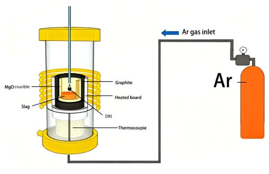
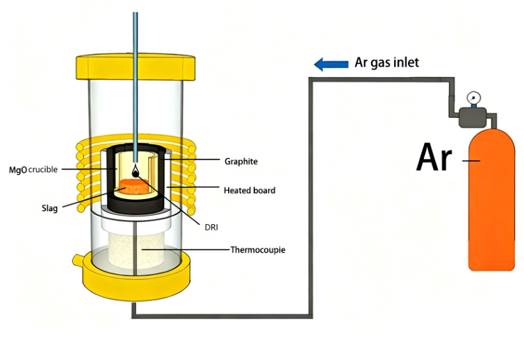
The experimental setup is shown in Figure 1. It consisted mainly of a vertical tube furnace, an alumina tube, a graphite crucible, an MgO crucible, and a gas supply system including an Ar cylinder, silicone tubing, and a gas flow meter.
Figure 1.
Schematic diagram of the hot-state melting apparatus for DRI.
The synthetic slags used in this study were prepared from analytically pure FeO, CaO, SiO2, Al2O3, MgO, MnO, and P2O5 powders. The designed slag compositions are listed in Table 1. The MgO crucible used in the experiments had an inner diameter of 40 mm, an outer diameter of 48 mm, and a height of 95 mm. The chemical composition of the DRI sample is given in Table 2.
Table 1.
Composition of the laboratory-prepared synthetic slags (wt.%).
Table 2.
Compositions of DRI (wt.%).
The P2O5 content was fixed at 3 wt.% for all slag compositions. This value was selected to represent a phosphorus-containing oxidizing slag condition rather than a universal composition of industrial slags, since the P2O5 content in actual steelmaking slags varies with raw materials, refining stage, slag basicity, and oxygen potential. In the present study, P2O5 was not considered as an independent variable; therefore, it was kept constant to minimize its influence on slag structure and interfacial reactions, allowing the effect of FeO content to be isolated.
The ash in the DRI was mainly composed of oxide gangue components, including SiO2, CaO, Al2O3, MgO, MnO, P2O5, and residual FeO, with SiO2, CaO, and FeO being the major constituents.
It should be noted that the slag composition during the high-temperature melting experiment may deviate from the nominal composition listed in Table 1 owing to FeO consumption by reaction with carbon and metallic iron in DRI, dissolution of DRI gangue components, and possible MgO dissolution from the crucible. Therefore, the FeO contents discussed in this work refer to the initial designed slag compositions. The local composition at the reaction interface may differ from the bulk slag composition, especially during the early stage of DRI melting. For this reason, the present study focuses mainly on the relative influence of initial FeO content on DRI melting behavior and interfacial evolution rather than on the absolute equilibrium slag composition during reaction.
The detailed procedures for the DRI hot-state melting experiment and subsequent microstructural analysis were as follows. The synthetic slag was prepared from analytically pure reagents mixed according to the prescribed proportions, and 200 g of slag was placed in a vertical tube furnace using an MgO crucible with a graphite outer crucible. The temperature was first raised to 1100 °C at a heating rate of 10 °C·min−1 and then to 1600 °C at 5 °C min−1, followed by holding for 30 min to ensure the homogeneity of the molten bath in both composition and temperature. During the experiment, high-purity argon was introduced at a flow rate of 1.5 L·min−1 to prevent oxidation of the slag and specimen. The DRI samples used in the hot-state melting experiments were approximately cylindrical pellets with an initial diameter of about 16 mm and a height of about 18 mm. Before immersion, the initial dimensions of each sample were measured using a vernier caliper, and samples with similar dimensions were selected to minimize the influence of initial size variation on the melting behavior. A small hole was drilled in the DRI sample, and the sample was fixed to a steel rod using molybdenum wire. After the molten bath reached a stable temperature, the DRI sample was vertically immersed into the molten slag. After the designated reaction time, the sample was rapidly withdrawn and quenched to preserve the high-temperature interfacial morphology. The quenched samples were then dried, and their characteristic dimensions at different reaction times were measured. The melting behavior of DRI was evaluated by monitoring the change in the apparent sample diameter with immersion time. The sample diameter was measured from the recorded images at 5 s intervals. For each time point, the apparent diameter was determined from the average of two perpendicular directions to reduce the influence of irregular sample deformation. The melting rate was evaluated from the slope of the diameter–time curve during the main shrinking stage after the maximum diameter was reached. The complete melting time was defined as the time at which the visible DRI body disappeared or lost its continuous contour in the molten slag. Each experiment was repeated three times, and the average value was taken to evaluate the DRI melting rate. Subsequently, the samples were mounted in epoxy resin, ground and polished stepwise with SiC papers, and examined by SEM (Guoyi Quantum, Hefei, Chinan) and EDS (Guoyi Quantum, Hefei, China) to analyze the interfacial reaction behavior and elemental distribution. In addition, slag samples were separately prepared for the characterization of slag properties and structure.
All hot-state melting and viscosity experiments were repeated three times under the same conditions. The reported values are the arithmetic mean values of the repeated measurements, and the error bars represent one standard deviation. For Arrhenius fitting, the uncertainty of the apparent viscous-flow activation energy was calculated from the standard error of the fitted slope.
2.2. Preparation and Characterization Methods of Slag Samples
To investigate the physical properties and structural characteristics of slags with different FeO contents, separate slag samples for property measurements and phase characterization were prepared according to the compositions listed in Table 1. The detailed preparation procedure was as follows.
A total of 200 g of analytically pure reagents was weighed according to the proportions in Table 1, thoroughly mixed, and charged into an MgO crucible, which was then placed inside a graphite crucible as a protective outer shell and subjected to pre-melting in a vertical tube furnace. During the experiment, high-purity argon was introduced at a flow rate of 1.5 L/min to provide a protective atmosphere. The furnace temperature was increased to 1600 °C and held for 30 min to ensure complete melting and homogenization of the synthetic slag. After the holding period, the crucible was rapidly removed and quenched in cold water to preserve the high-temperature equilibrium structure. The quenched slag samples were then dried in an oven at 120 °C for 4 h. A portion of each quenched slag sample was ground thoroughly in an agate mortar and sealed for subsequent characterization, including phase identification and melting characteristic measurements.
2.2.1. Rheological Property Measurement
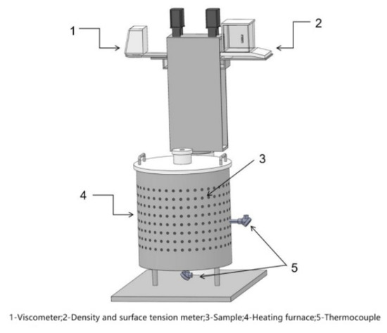
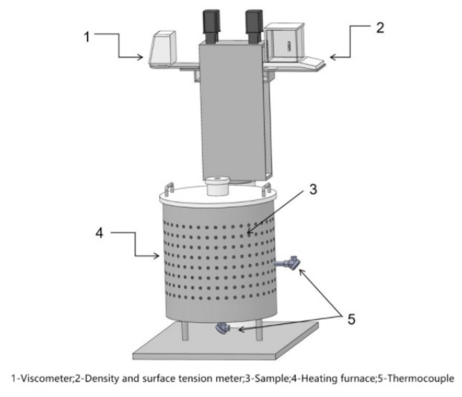
The viscosity of the synthetic slag samples was measured using a slag viscosity measurement system (MTLQ-ND-9 Meite Furnace Industry, Luoyang, China), as shown in Figure 2. The viscosity test was performed using the rotary cylinder method. A cylindrical molybdenum spindle was positioned at the center of the MgO crucible. The distance between the bottom of the spindle and the crucible bottom was maintained at approximately 10 mm, and the slag level was adjusted so that approximately half of the spindle height was immersed in the molten slag. During the test, the probe was rotated at a constant angular velocity. The slag viscosity was calculated by measuring the torque generated on the probe surface due to viscous resistance, together with the corresponding geometrical and temperature parameters. Each viscosity measurement was repeated three times under identical conditions. The viscosity values are reported as mean values, and the corresponding standard deviations were used as error bars to evaluate the reproducibility of the measurements.
Figure 2.
Slag viscosity measurement system.
The slag viscosity was calculated from the measured torque using the calibrated instrument constant:
where η is the viscosity of the molten slag, Pa·s; K is the calibrated instrument constant; M is the measured torque, N·m; and ω is the angular velocity of the rotating spindle, rad·s−1.
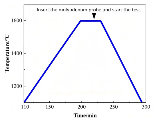
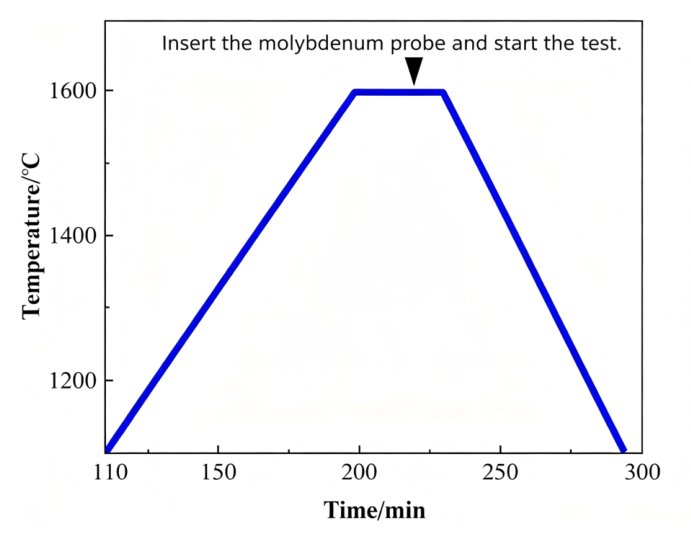
The viscosity test was conducted under an argon atmosphere at a flow rate of 1.5 L/min. The furnace was heated to 1600 °C and held for 30 min to fully homogenize the slag sample. After inserting the molybdenum probe, the temperature was decreased at a rate of 3 °C·min−1 while the viscosity was recorded. After the test, the probe was removed, and the furnace was reheated to 1600 °C and held for another 30 min. Subsequently, the MgO crucible was quenched in water to obtain the slag sample for further characterization. The temperature control program used for the viscosity measurement is shown in Figure 3.
Figure 3.
Temperature control program for synthetic slag viscosity measurement.
2.2.2. Melting Characteristic Test
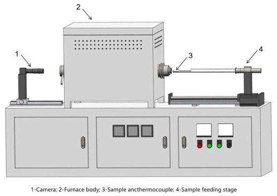
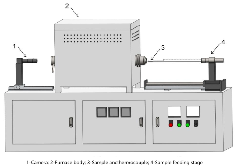
The melting characteristics of the synthetic slag samples were evaluated using a slag melting point and melting rate measurement system (MTLQ-RD-1600 Meite Furnace Industry, Luoyang, China), as shown in Figure 4. This system determines the characteristic melting temperatures of slag based on the hemispherical temperature method. During heating, images of the sample were collected in real time using a high-resolution camera, and the image recognition system was employed to automatically identify the sample contour and height variation. Based on the ratio of the sample height to its original height, the system automatically recorded the characteristic images and the corresponding temperatures during the melting process.
Figure 4.
Slag melting point and melting rate measurement system.
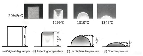
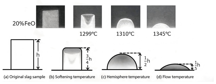
In the experiment, the synthetic slag powder was placed in a cylindrical mold with dimensions of Φ3 × 3 mm. After compaction, the cylindrical sample was removed from the mold and heated in the furnace. When the sample height decreased to three-quarters of its original height, the corresponding temperature was defined as the softening temperature. When the sample height decreased to one-half of its original height, the corresponding temperature was defined as the hemispherical temperature. When the sample height decreased to one-quarter of its original height, the corresponding temperature was defined as the flow temperature, as shown in Figure 5.
Figure 5.
Definition of characteristic melting temperatures based on the hemispherical method.
3. Results
3.1. Effect of FeO Content on the Melting Rate of DRI
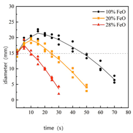
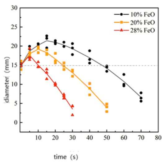
To evaluate the effect of FeO content on the melting behavior of DRI, high-temperature melting experiments were carried out using synthetic slags with FeO contents of 10, 20, and 28 wt.%, respectively, and the change in sample diameter was measured at 5 s intervals over the range of 0–70 s.
As shown in Figure 6, the diameters of all three samples first increased and then decreased, indicating that the melting process of DRI proceeded in distinct stages. Under different FeO contents, both the magnitude of diameter change and the time at which the peak occurred showed significant differences. For the 10% FeO slag, the sample exhibited the largest peak diameter, approximately 21 mm, and maintained this value for a relatively long time, indicating the lowest melting rate. As the FeO content increased to 20%, the peak diameter decreased to about 19 mm, and the melting process accelerated noticeably. When the FeO content was further increased to 28%, the peak diameter dropped to about 17 mm, followed by a more rapid contraction, suggesting that the DRI melting rate was highest under high-FeO conditions.
Figure 6.
Variation in DRI diameter with melting time under different FeO contents. The data are presented as the mean values of three repeated experiments, and the error bars represent the corresponding standard deviations.
The error bars in Figure 6 represent the standard deviations of three repeated experiments. The relatively small deviations indicate good reproducibility of the diameter measurements and confirm the reliability of the observed melting behavior.
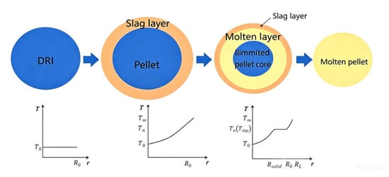
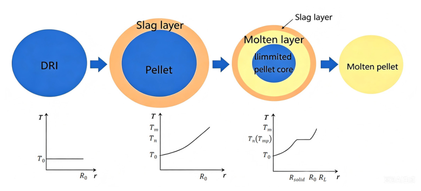
The overall results suggest that the formation and subsequent melting of the solidified slag shell play an important role in the staged melting behavior of DRI in molten slag. The typical staged melting behavior of DRI is schematically illustrated in Figure 7.
Figure 7.
Schematic diagram of staged melting process of DRI in high-temperature molten slag.
3.2. Effect of FeO Content on Physical Properties of Molten Slag
The viscosity of molten slag directly affects its fluidity, wetting and penetration ability toward DRI, and interfacial mass-transfer behavior, thereby influencing the melting rate of DRI. In general, lower slag viscosity facilitates slag spreading and enveloping of the DRI sample and promotes the diffusion of active species in the slag phase. Therefore, slag viscosity is one of the key parameters governing the kinetic conditions of DRI melting.
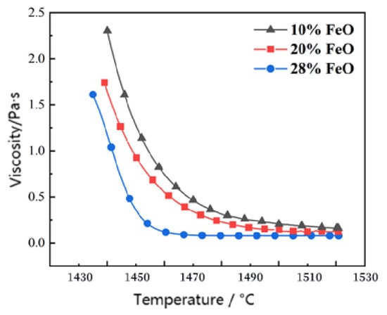
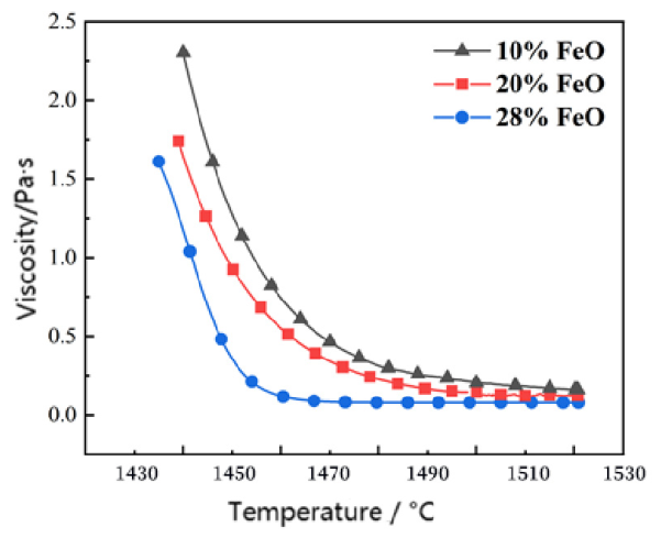
As shown in Figure 8, the viscosity of all experimental slags increased during cooling, indicating that decreasing temperature reduces slag fluidity. At temperatures above approximately 1510 °C, the viscosities of the slags with different FeO contents were all relatively low and close to each other, suggesting that the influence of FeO content on slag viscosity was limited in the fully molten high-temperature region. This may be because the slag structure was sufficiently depolymerized at high temperature, and the viscosity was mainly governed by the overall liquid-state structure rather than by the FeO content alone. The error bars in Figure 8 represent the standard deviations of three repeated viscosity measurements. The relatively small deviations indicate good reproducibility of the viscosity tests and provide statistical support for the observed viscosity variation trends.
Figure 8.
Viscosity curves of synthetic slags with different FeO contents during cooling. The data are presented as the mean values of three repeated measurements, and the error bars represent the corresponding standard deviations.
However, with decreasing temperature, the difference in viscosity among the slags became more evident. The slag with higher FeO content exhibited a lower viscosity and a slower increase in viscosity during cooling, indicating that FeO plays a more pronounced role in improving slag fluidity in the lower-temperature region or near the melting/solidification range. Therefore, the effect of FeO on DRI melting should not be attributed solely to a large viscosity difference at temperatures above 1510 °C, but rather to its combined influence on slag fluidity during cooling, melting characteristics, interfacial wettability, penetration behavior, and heat-transfer capability. This indicates that increasing FeO content can improve the high-temperature flowability of the slag, thereby providing more favorable kinetic conditions for DRI melting.
To further quantitatively analyze the temperature dependence of slag viscosity, the viscosity–temperature relationship was described using the standard Arrhenius-type equation:
where η is the slag viscosity, Pa·s; A is the pre-exponential factor; Eη is the apparent activation energy for viscous flow, J·mol−1; R is the gas constant, 8.314 J·mol−1·K−1; and T is the absolute temperature, K.
Taking the natural logarithm of both sides gives:
To reduce the cross-correlation between the pre-exponential factor and the apparent viscous-flow activation energy, the temperature-centering method was adopted. The centered Arrhenius equation can be expressed as:
where T0 is the reference temperature selected as the midpoint of the fitted temperature range. In this study, T0 was set to 1748.15 K, corresponding to the midpoint of the experimental temperature interval for fitting denotes the fitted logarithmic viscosity at the reference temperature T0 In this temperature-centered formulation, the fitted slope equals Eη/R this form endows the intercept with a distinct physicochemical meaning and greatly weakens the cross-correlation between the fitted slope and intercept. The absolute uncertainty of Eη was derived from the standard error of the fitted slope, and the relative percentage uncertainty was adopted to quantify the statistical reliability of each fitted apparent viscous-flow activation energy.
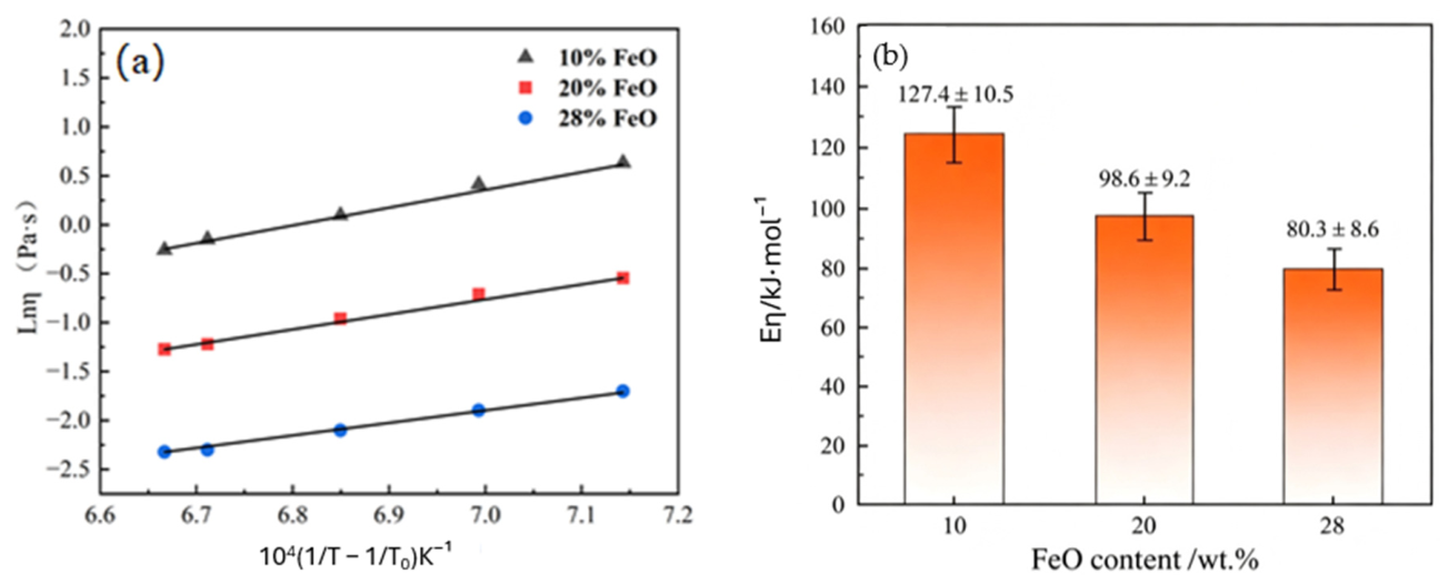
The temperature-centered Arrhenius fitting results are shown in Figure 9 and summarized in Table 3. The relative percentage uncertainty of each fitted activation energy was calculated from the fitting covariance matrix to evaluate the statistical reliability of the fitted parameters. As shown in Figure 9b and Table 3, the apparent viscous-flow activation energy shows a decreasing fitted trend, but viscosity reduction cannot be attributed solely to this factor.
Figure 9.
Temperature-centered Arrhenius analysis of the viscosity–temperature relationship of slags with different FeO contents: (a) linear fitting between and ; (b) apparent viscous-flow activation energies calculated from the fitted slopes. The error bars in (b) represent the uncertainties of the fitted activation energies.
Table 3.
Temperature-centered Arrhenius fitting parameters for slags with different FeO contents.
Since the apparent viscous-flow activation energy is proportional to the fitted slope, the small difference in the slopes among the three slags indicates that the viscosity difference cannot be simply attributed to a significant decrease in activation energy. Instead, the fitting results suggest that changes in the fitted intercept or pre-exponential-related term, slag structural characteristics, and temperature-dependent flow behavior also contribute to the observed viscosity variation. Overall, increasing FeO content improves slag fluidity, especially in the lower-temperature region, thereby enhancing slag wettability, penetration ability, and interfacial mass transfer during DRI melting. During DRI melting, a diffusion boundary layer may form near the interface owing to FeO consumption, gangue accumulation, and local compositional enrichment. Lower slag viscosity reduces mass-transfer resistance in this interfacial region and promotes the migration of ions or structural units in the slag, thereby facilitating DRI melting.
3.3. FactSage Calculation of Slag Thermal Conductivity
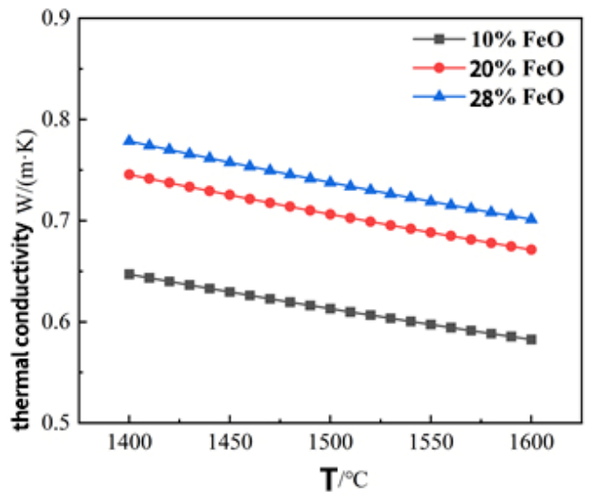
Heat transfer is an important factor affecting the melting behavior of DRI, and the thermal conductivity of the slag is closely related to the heat-transfer efficiency from the molten slag to the DRI surface. To evaluate the influence of FeO content on the heat-transfer characteristics of the slag, the thermal conductivity of slags with different FeO contents at 1400–1600 °C was calculated using FactSage 8.2 thermochemical software [20].
As shown in Figure 10, the calculated results indicate that the thermal conductivity of the slag shows an increasing trend with increasing FeO content in the temperature range of 1400–1600 °C. This suggests that increasing FeO content is beneficial for improving heat transfer through the slag phase. Combined with the viscosity results, the increase in FeO content simultaneously decreases slag viscosity and enhances the heat-transfer capability of the slag. These two effects act synergistically to improve the kinetic conditions for DRI melting, which is one of the main reasons for the accelerated melting rate of DRI under high-FeO conditions.
Figure 10.
FactSage-calculated thermal conductivity of slags with different FeO contents.
Nevertheless, the FactSage calculation in this study is mainly used to evaluate the relative variation trend of thermal conductivity among slags with different FeO contents, rather than to provide an absolute prediction of the thermal conductivity values. Therefore, the calculated results should be interpreted together with the experimentally measured viscosity and melting behavior.
4. Discussion
4.1. Microstructure and Interfacial Reaction at the DRI–Slag Interface
To further investigate the effect of FeO content on DRI melting behavior, the DRI–slag interfaces after 10 s of immersion in synthetic slags with different FeO contents at 1600 °C were examined by SEM. The results indicate that FeO content strongly affects the morphology of the interfacial reaction layer and the slag penetration behavior.
Taking the sample reacted with the 28 wt.% FeO slag as an example, a distinct slag-adhered region was observed on the DRI surface, indicating rapid contact between the molten slag and the sample surface within a short time, as shown in Figure 11. Compared with the interior region away from the interface, the grayscale of the DRI matrix near the interface changed noticeably, suggesting the inward migration of slag constituents and the occurrence of interfacial reactions.
Figure 11.
SEM morphology of the DRI–slag interface after reaction with the 28 wt.% FeO slag at 1600 °C for 10 s.
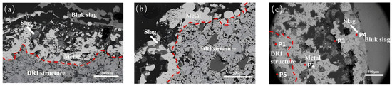
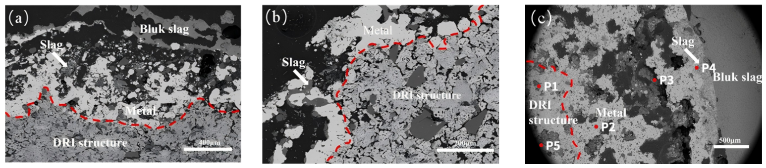
As shown in Figure 12, from the overall cross-sectional morphology, the DRI–slag interface can be roughly divided into three regions: an outer slag-rich region, a middle molten or near-molten iron region, and an inner partially unmelted DRI pore-network region. This structure suggests that DRI melting does not proceed as a simple uniform outward-to-inward process, but rather involves coupled slag penetration, local metallic phase evolution, and interfacial reaction-layer development. With increasing FeO content, the morphology of the interfacial transition region changes markedly, indicating enhanced slag penetration and stronger interfacial interaction.
Figure 12.
Overall morphology of the DRI–slag interface after 10 s of reaction at 1600 °C under different FeO contents: (a) 10 wt.% FeO; (b) 20 wt.% FeO; (c) 28 wt.% FeO. The marked regions P1–P5 in (c) indicate representative areas selected for semi-quantitative EDX analysis.
The semi-quantitative EDX results of the representative regions marked in Figure 12c are summarized in Table 4. Regions P1 and P2 are characterized by high Fe contents, corresponding to the Fe-rich DRI matrix and metallic Fe region, respectively. The small amounts of O, Si, Ca, Al, and P detected in P1 are associated with residual FeO and oxide gangue components in the DRI. Region P3 contains both Fe and slag-forming elements, indicating the formation of a slag–iron mixed reaction zone. Region P4 is enriched in O, Ca, Si, Mg, and Al, confirming its slag-rich nature near the interface. Region P5 contains considerable Fe together with slag-forming elements, suggesting that molten slag penetrated into the porous DRI structure under high-FeO conditions.
Table 4.
Semi-quantitative EDX analysis of representative regions marked in Figure 12c (wt.%).
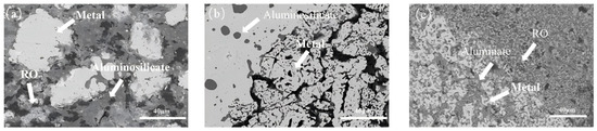
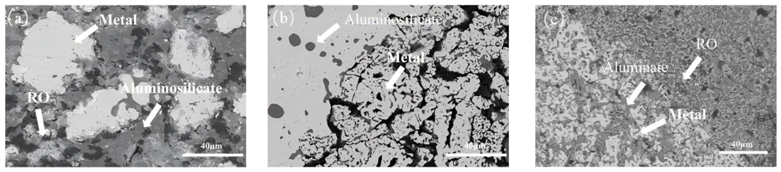
As shown in Figure 13, the interfacial microstructures under different FeO contents further indicate that, under low-FeO conditions, the interface between DRI and slag is relatively distinct, and the reaction layer formed on the surface is fairly continuous, thereby impeding further slag penetration. In this case, the slag remains mainly on the sample surface, and the degree of internal penetration is limited, suggesting a relatively slow interfacial reaction. Therefore, the barrier effect of the surface reaction layer and solidified slag shell may contribute to the slower melting of DRI under low-FeO conditions.
Figure 13.
SEM morphology of the DRI–molten slag interface under different FeO contents: (a) 10 wt.% FeO; (b) 20 wt.% FeO; (c) 28 wt.% FeO. RO denotes a divalent metal oxide solid solution phase, where R represents divalent cations such as Fe2+, Mg2+, Mn2+, and Ca2+.
When the FeO content increased to 20 wt.%, the interfacial boundary became less distinct, and the continuity of the original dense interfacial layer weakened, allowing the slag to further penetrate into the DRI through surface pores. At this stage, spherical or droplet-like slag inclusions were observed locally within the metallic phase, indicating that slag entered the interior of the sample through the pore network. Compared with the low-FeO condition, the slag exhibited improved wettability and fluidity, while the interfacial resistance was reduced; consequently, the DRI melting rate increased.
When the FeO content was further increased to 28 wt.%, the interfacial transition zone became markedly wider, and a large amount of slag penetrated into the internal pore network of the DRI, forming an extensive slag–iron mixed reaction zone near the interface. Meanwhile, the metallic iron region became more discontinuous and dispersed, indicating more pronounced slag penetration into the DRI under high-FeO conditions.
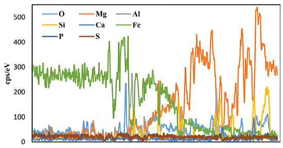
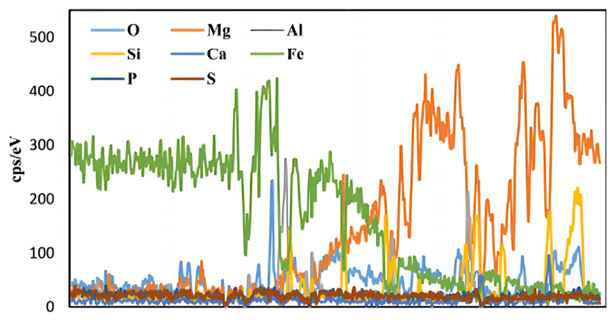
To further examine the elemental migration across the DRI–slag interface, EDS line-scanning analysis was carried out, as shown in Figure 14. The Fe signal was dominant on the DRI side, whereas O, Mg, Si, Ca, and Al increased toward the slag-rich region. This distribution indicates the migration of slag-forming components into the porous DRI structure and the formation of an interfacial reaction zone.
Figure 14.
EDS line-scanning profiles across the DRI–molten slag interface after reaction with the 28 wt.% FeO slag at 1600 °C for 10 s.
The overlapping distribution of Fe and slag-forming elements suggests that the observed DRI–slag interface was not a sharp boundary but rather a slag–iron mixed reaction zone. This result supports the SEM observations that higher FeO content promotes slag penetration and enhances interfacial reactions, thereby facilitating DRI melting.
In summary, FeO content strongly influences the interfacial morphology and reaction mode of the DRI–slag system. Under low-FeO conditions, a relatively continuous aluminosilicate-rich reaction layer forms at the interface, acting as a barrier to slag penetration and thereby hindering DRI melting. At intermediate FeO contents, the continuity of the interfacial layer weakens, allowing slag to penetrate into the DRI interior and intensifying the interfacial reaction. Under high-FeO conditions, the slag more readily wets and penetrates the DRI pore network, leading to the formation of a large slag–iron mixed reaction zone at the interface. The semi-quantitative EDX results and line-scanning profiles further confirm that the interfacial transition zone contains both Fe and slag-forming elements, indicating the coupling of slag penetration and metallic phase evolution. This increases the slag–metal contact area and promotes interfacial reactions. These results are consistent with the experimental observation that increasing FeO content accelerates DRI melting, suggesting that FeO promotes DRI melting mainly by improving slag wettability, penetration ability, and interfacial reaction kinetics.
4.2. Microstructure and Interfacial Reaction at the Slag–Refractory Interface
To further clarify the influence of FeO content on the overall stability of the DRI melting system, the microstructure of the interface between molten slag and the MgO refractory was analyzed. The results indicate that a distinct reaction transition layer formed at the slag–refractory interface under high-temperature conditions, and its morphology and thickness varied with FeO content [21].
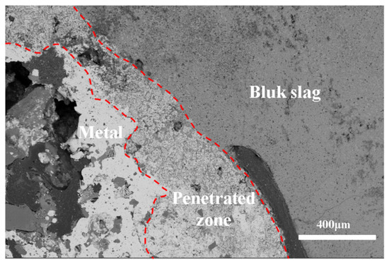
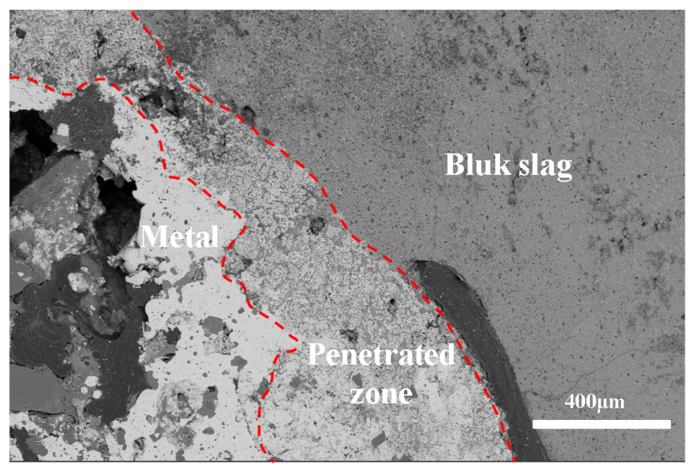
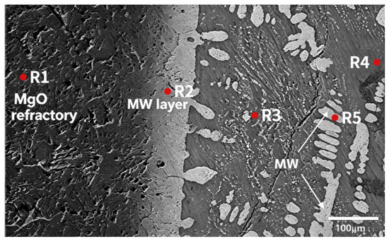
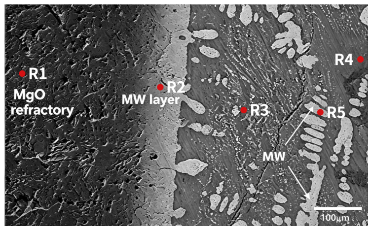
As shown in Figure 15, a continuous and relatively dense reaction layer was observed at the slag–MgO refractory interface. This layer exhibited a compact structure and good interfacial bonding, with no obvious pores, cracks, or debonding detected. Based on the interfacial morphology and reported slag–refractory interaction mechanisms involving magnesia-based refractories and iron-bearing slags [22]. this reaction layer can be attributed mainly to the formation of a magnesiowüstite phase, namely MW ((Mg,Fe)O), through Fe2+/Mg2+ interdiffusion. With increasing FeO content, the Fe-bearing slag provides a stronger driving force for Fe2+ diffusion toward the refractory side, thereby promoting the growth of the MW-rich interfacial layer.
Figure 15.
SEM morphology of the slag–MgO refractory interface after high-temperature reaction with the 28 wt.% FeO slag. R1–R5 indicate representative regions selected for semi-quantitative EDX analysis.
To further verify the chemical characteristics of the interfacial reaction products, semi-quantitative EDX analysis was performed on representative regions at the slag–MgO refractory interface, as summarized in Table 5. The MgO refractory matrix, represented by R1, is mainly composed of Mg and O, with only trace amounts of Fe and slag-forming elements. In contrast, R2 contains significant amounts of Mg, Fe, and O, supporting the formation of an MW-rich magnesiowüstite ((Mg,Fe)O) interfacial reaction layer through Fe2+/Mg2+ interdiffusion. R3 contains Mg and O together with Fe, Ca, Si, Al, Mn, and P, indicating that molten slag penetrated into the refractory matrix and formed a slag-infiltrated reaction zone. R4 is enriched in Ca, Fe, O, Si, and Mg, corresponding to the adjacent slag region. In addition, R5 contains high Fe, Mg, and O contents but only minor amounts of slag-forming elements, further supporting the precipitation of an MW phase near the slag–refractory interface. These EDX results provide direct compositional evidence for the proposed slag–refractory interfacial reaction mechanism.
Table 5.
Semi-quantitative EDX analysis of representative regions at the slag–MgO refractory interface marked in Figure 15 (wt.%).
From the perspective of interfacial evolution, when the FeO content was low, the slag exhibited relatively limited fluidity and penetration capability. Under these conditions, only limited reaction products were observed near the slag–refractory interface, and a continuous reaction layer was not fully developed. The refractory matrix remained largely intact, suggesting that the interfacial reaction was relatively weak and that corrosion was mainly confined to the near-surface region.
As the FeO content increased, Fe-containing species in the slag more readily migrated toward the MgO refractory and participated in interfacial solid-solution reactions. This promoted the development and densification of the MW-rich reaction layer. Meanwhile, the interfacial reaction zone became wider, and slag wetting and local penetration into the refractory were more pronounced, indicating intensified slag–refractory interaction under high-FeO conditions.
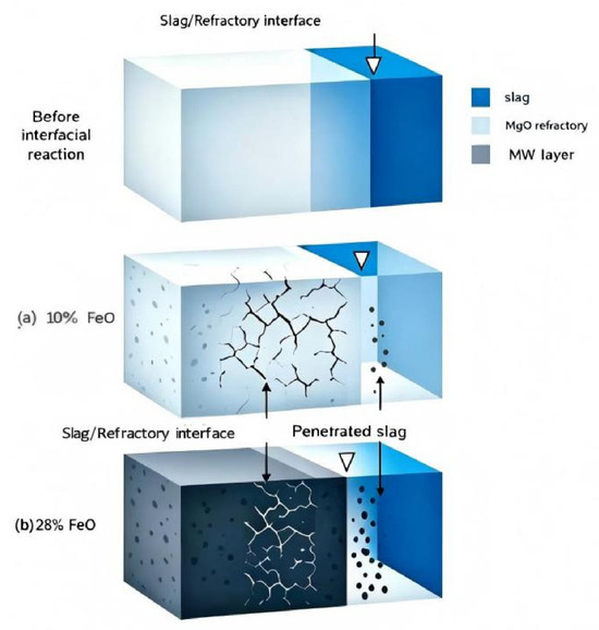
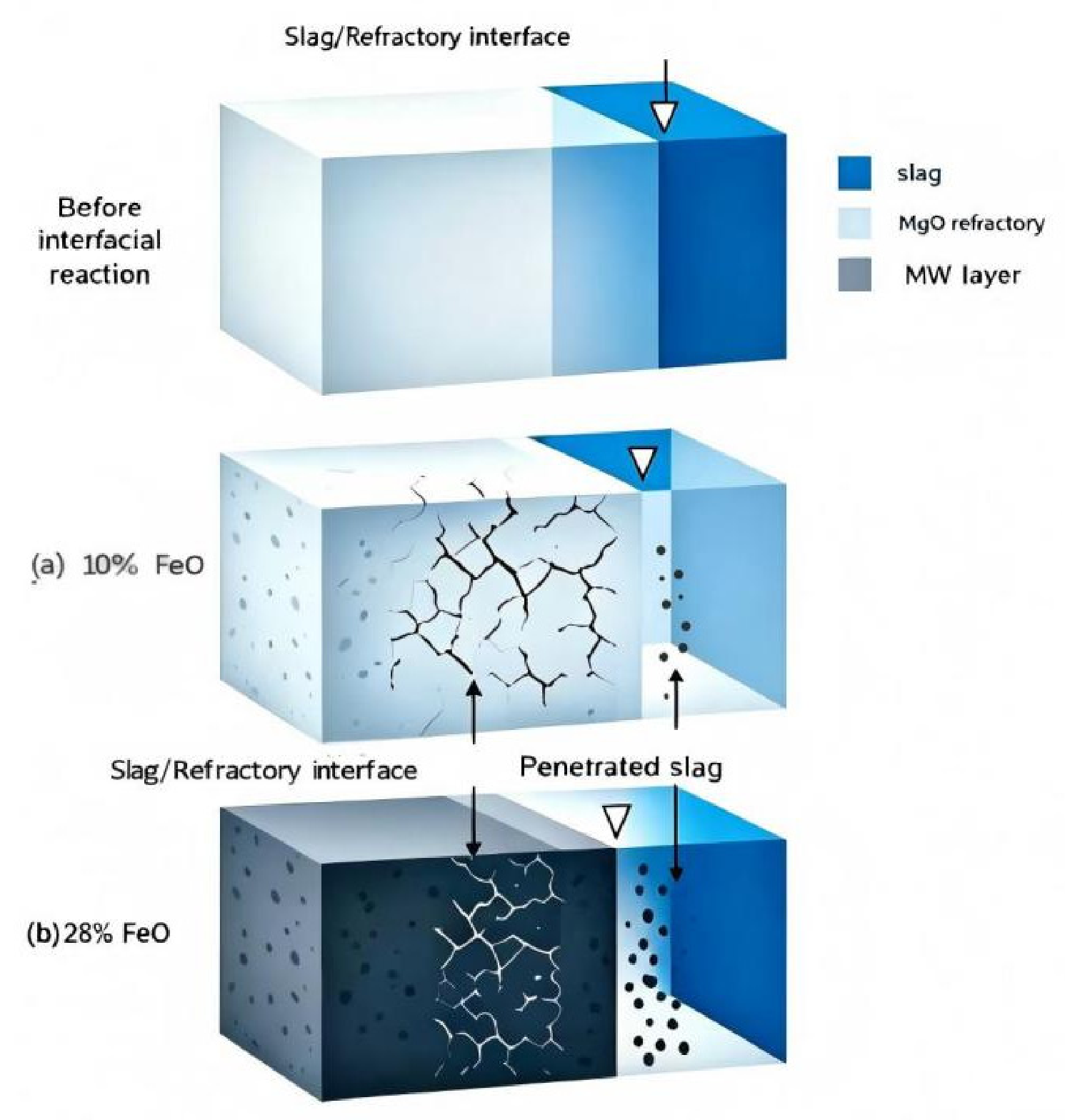
Figure 16 further compares the reaction characteristics of the slag–refractory interface under low- and high-FeO conditions. Under low-FeO conditions, corrosion of the MgO refractory by the slag was relatively weak, with only slight interfacial penetration and a dispersed distribution of reaction products. In contrast, under high-FeO conditions, the slag penetrated more deeply into the refractory, the reaction layer became thicker, and matrix cracking or local spalling was observed, indicating an increase in interfacial corrosion intensity.
Figure 16.
Schematic diagram of slag–refractory interfacial reactions under low- and high-FeO conditions.
Overall, increasing FeO content intensifies the interfacial reaction between molten slag and the MgO refractory, promotes the development of the MW-rich reaction layer, and enhances slag penetration and refractory corrosion. Although the MW-rich interlayer may provide a certain barrier effect against direct slag attack, its thickness and stability are closely related to FeO content. At high FeO contents, intensified interfacial reactions can lead to structural degradation of the refractory. Therefore, FeO not only affects the DRI melting rate but also regulates slag–refractory interfacial behavior, thereby influencing the overall stability of the DRI melting system.
5. Conclusions
This study investigated the effect of FeO content on the melting behavior of direct reduced iron (DRI) and the associated interfacial reactions in slag–metal–refractory systems. Based on hot-state melting experiments, slag property measurements, FactSage-based calculations, and SEM/EDS characterization, the following conclusions can be drawn:
- Increasing the initial FeO content promoted the apparent melting of DRI under the present experimental conditions.
Increasing FeO content reduced slag viscosity and increased the calculated thermal conductivity of the slag. Temperature-centered Arrhenius fitting showed that the apparent viscous-flow activation energies varied only within a limited range when fitting uncertainties were considered, suggesting that the FeO-induced viscosity decrease cannot be attributed solely to a reduction in activation energy. These changes are expected to improve slag fluidity, interfacial mass transfer, and heat-transfer conditions during DRI melting.
- 2.
- FeO content alters the microstructure and reaction behavior at the DRI–slag interface.
Under low-FeO conditions, a relatively continuous aluminosilicate-rich reaction layer formed at the interface, which hindered further slag penetration and slowed interfacial reactions. As FeO content increased, the barrier effect of this interfacial layer weakened, allowing slag to penetrate inward along the DRI pore network. The semi-quantitative EDX results confirmed the coexistence of Fe and slag-forming elements in the interfacial transition zone, providing compositional evidence for slag penetration and the formation of the slag–iron mixed reaction zone. An extensive slag–iron mixed reaction zone then formed at the interface, increasing the slag–metal contact area and promoting interfacial reactions, which is consistent with the accelerated DRI melting behavior.
- 3.
- An MW-rich reaction transition layer was observed at the slag–MgO refractory interface.
At the slag–MgO refractory interface, FeO promoted Fe2+/Mg2+ interdiffusion and the formation of an MW-rich magnesiowüstite ((Mg,Fe)O) interfacial layer. With increasing FeO content, this reaction layer tended to become thicker and more developed. Although the MW-rich layer may partially hinder direct slag attack on the MgO matrix, high-FeO slags also enhanced slag penetration and refractory corrosion, leading to structural degradation of the refractory.
- 4.
- FeO regulates DRI melting through coupled slag–metal and slag–refractory interactions.
FeO regulated DRI melting through coupled effects on slag properties and interfacial reactions. Increasing FeO content improved slag fluidity and heat-transfer capability, promoted slag penetration into the porous DRI structure, and enhanced slag–metal interfacial reactions, thereby accelerating DRI melting. However, high FeO content also intensified slag–MgO refractory interaction and corrosion. Therefore, in practical smelting processes, FeO content should be optimized to balance DRI melting efficiency and refractory lining stability.
Author Contributions
Conceptualization, J.W. and L.C.; methodology, J.W.; validation, J.W. and L.C.; formal analysis, J.W.; investigation, J.W.; resources, J.W.; data curation, J.W.; writing—original draft preparation, J.W.; writing—review and editing, J.W. and L.C.; visualization, J.W.; supervision, L.C.; project administration, L.C.; funding acquisition, L.C. All authors have read and agreed to the published version of the manuscript.
Funding
This research received no external funding.
Data Availability Statement
The original contributions presented in this study are included in the article. Further inquiries can be directed to the corresponding author.
Acknowledgments
I am deeply thankful to my supervisor, who offered constant professional guidance, insightful comments and patient revisions from the design of experiments to the completion of this manuscript. In addition, I would like to acknowledge Wang and Ge Chaoxue for providing practical assistance and helpful discussions in the course of this research.
Conflicts of Interest
The authors declare no conflict of interest.
References
- Kim, W.; Sohn, I. Critical challenges facing low carbon steelmaking technology using hydrogen direct reduced iron. Joule 2022, 6, 2228–2232. [Google Scholar] [CrossRef] [Scilit]
- Shahabuddin, M.; Brooks, G.; Rhamdhani, M.A. Decarbonisation and hydrogen integration of steel industries: Recent development, challenges and technoeconomic analysis. J. Clean. Prod. 2023, 395, 136391. [Google Scholar] [CrossRef] [Scilit]
- Lopez, G.; Farfan, J.; Breyer, C. Trends in the global steel industry: Evolutionary projections and defossilisation pathways through power-to-steel. J. Clean. Prod. 2022, 375, 134182. [Google Scholar] [CrossRef] [Scilit]
- Ncube, N.Y.R.; Ayomoh, M. Optimisation Strategies and Technological Advancements for Sustainable Direct Reduction Iron Production—A Systematic Review. Sustainability 2025, 17, 2266. [Google Scholar] [CrossRef] [Scilit]
- Azimi, A.; Spek, D.V.M. Prospective Life Cycle Assessment Suggests Direct Reduced Iron Is the Most Sustainable Pathway to Net-Zero Steelmaking. Ind. Eng. Chem. Res. 2025, 64, 3871–3885. [Google Scholar] [CrossRef] [Scilit] [PubMed]
- Immonen, J.; Powell, M.K. Dynamic modeling of a direct reduced iron shaft furnace to enable pathways towards decarbonized steel production. Chem. Eng. Sci. 2024, 300, 120637. [Google Scholar] [CrossRef] [Scilit]
- Xi, X.; Li, S.; Li, C.; Pan, H.; Wang, J.; Zhu, R. Research on technical parameters of electrical arc furnace steelmaking based on direct reduced iron as raw material. Ironmak. Steelmak. 2024, 51, 947–960. [Google Scholar] [CrossRef] [Scilit]
- Visuri, V.-V.; Echterhof, T. Electric Arc Furnace Steelmaking. Metals 2025, 15, 1285. [Google Scholar] [CrossRef] [Scilit]
- Morales, R.D.; Conejo, A.N.; Rodriguez, H.H. Process dynamics of electric arc furnace during direct reduced iron melting. Metall. Mater. Trans. B 2002, 33, 187–199. [Google Scholar] [CrossRef] [Scilit]
- Rafiei, A.; Dogan, N.; Sun, S. Experimental and Kinetic Study of Melting Hydrogen-Direct Reduced Iron (H-DRI) and Commercial DRI Pellets in EAF Slag. Metall. Mater. Trans. B 2026, 57, 3859–3878. [Google Scholar] [CrossRef] [Scilit]
- Calderon Hurtado, F.A.; Govro, J.; Emdadi, A.; O’Malley, R.J. The Melting Behavior of Hydrogen Direct Reduced Iron in Molten Steel and Slag: An Integrated Computational and Experimental Study. Metals 2024, 14, 821. [Google Scholar] [CrossRef] [Scilit]
- Cai, Y.; Zou, Y.; Yang, L.; Liu, F.; Wei, G.; Li, G.; Zhang, Y.; Jiang, T. Mechanism and optimization conditions of direct reduced iron melting process: A study based on numerical simulation and experimental validation. J. Mater. Res. Technol. 2026, 42, 2394–2411. [Google Scholar] [CrossRef] [Scilit]
- Vickerfält, A.; Huss, J.; Martinsson, J.; Sichen, D. Reaction mechanisms during melting of H-DRI focusing on slag formation and the behavior of vanadium. Metall. Mater. Trans. B 2023, 54, 2206–2215. [Google Scholar] [CrossRef]
- Vickerfält, A.; Martinsson, J.; Sichen, D. Effect of reduction degree on characteristics of slag formed by melting hydrogen-reduced DRI and partitions of P and V between slag and metal. Steel Res. Int. 2021, 92, 2000432. [Google Scholar] [CrossRef] [Scilit]
- Huss, J.K.J.; Vickerfält, A. Some Aspects of the melting and dephosphorization mechanism of hydrogen-DRI. Steel Res. Int. 2023, 94, 2300064. [Google Scholar]
- Heo, J.H.; Park, J.H. Effect of Direct Reduced Iron (DRI) on Dephosphorization of Molten Steel by Electric Arc Furnace Slag. Metall. Mater. Trans. B 2018, 49, 3381–3389. [Google Scholar] [CrossRef] [Scilit]
- Ammasi, A.; Rahul Karthik, P.M.; Vishal, D. Slag-Metal-Refractory Interactions During Dissolution of Hydrogen-Based Directly Reduced Iron (H-DRI) in Liquid Iron Melt. J. Sustain. Metall. 2024, 10, 542–556. [Google Scholar] [CrossRef] [Scilit]
- Heo, J.; Park, J.H. Interfacial Reactions Between Magnesia Refractory and Electric Arc Furnace (EAF) Slag with Use of Direct Reduced Iron (DRI) as Raw Material. Ceram. Int. 2022, 48, 4526–4538. [Google Scholar] [CrossRef] [Scilit]
- Han, J.S.; Heo, J.H.; Park, J.H. Interfacial Reaction Between Magnesia Refractory and “FeO”-Rich Slag: Formation of Magnesiowüstite Layer. Ceram. Int. 2019, 45, 10481–10491. [Google Scholar] [CrossRef] [Scilit]
- Lee, W.E.; Zhang, S. Melt Corrosion of Oxide and Oxide-Carbon Refractories. Int. Mater. Rev. 1999, 44, 77–104. [Google Scholar] [CrossRef] [Scilit]
- Bale, C.W.; Bélisle, E.; Chartrand, P.; Decterov, S.A.; Eriksson, G.; Hack, K.; Jung, I.H.; Kang, Y.B.; Melancon, J.; Pelton, A.D.; et al. FactSage thermochemical software and databases—Recent developments. Calphad 2009, 33, 295–311. [Google Scholar] [CrossRef] [Scilit]
- Sarkar, A.; Nash, M.; Sohn, H.-Y. Interactions of Alumina-Based and Magnesia-Based Refractories with Iron Melts and Slags. Metall. Mater. Trans. B 2018, 49, 2027–2042. [Google Scholar] [CrossRef] [Scilit]

Disclaimer/Publisher’s Note: The statements, opinions and data contained in all publications are solely those of the individual author(s) and contributor(s) and not of MDPI and/or the editor(s). MDPI and/or the editor(s) disclaim responsibility for any injury to people or property resulting from any ideas, methods, instructions or products referred to in the content. |
© 2026 by the authors. Licensee MDPI, Basel, Switzerland. This article is an open access article distributed under the terms and conditions of the Creative Commons Attribution (CC BY) license.