


Abstract
In marine service environments, material surfaces inevitably suffer from wear damage, which can compromise the integrity of protective coatings and further affect their corrosion resistance. Therefore, investigating the post-wear corrosion resistance of coatings is of great significance. In this work, single-layer CrN coatings, CrAlN coatings, and CrN/CrAlN multilayer coatings were deposited on stainless-steel substrates by arc ion plating, and the microstructure, tribological properties, and corrosion behavior before and after wear were systematically investigated. Wear tests were performed under applied loads of 2.5 N and 5 N. The corrosion behavior in the unworn condition and the post-wear corrosion resistance condition was evaluated in a 3.5 wt.% NaCl solution. The results showed that all coatings exhibited a face-centered cubic (FCC) structure, while the CrN/CrAlN multilayer coating possessed the smallest average grain size (13.47 nm). Under applied loads of 2.5 N and 5 N, the CrN/CrAlN multilayer coating exhibited the lowest wear rate, indicating the best wear resistance. In the unworn condition, the CrN/CrAlN multilayer coating showed the lowest corrosion current density (2.74 × 10⁻¹⁰ A/cm2) and the most positive corrosion potential (0.025 V), demonstrating the best corrosion resistance. After wear under a load of 5 N, the CrN/CrAlN multilayer coating retained a low corrosion current density (3.35 × 10⁻¹⁰ A/cm2), in contrast to the marked increases observed for the single-layer coatings. The enhanced performance is considered to be mainly associated with the periodic heterogeneous interfaces in the multilayer structure, which help suppress crack propagation and prolong the penetration path of corrosive media.
1. Introduction
In marine engineering, petrochemical industries, and nuclear power systems, metallic components are often exposed to both mechanical wear and corrosive media during service [1,2]. The interaction between these factors can accelerate material degradation, a phenomenon that is particularly pronounced in widely used structural materials such as stainless steel [3]. The wear process disrupts the passive film on the material surface, exposing fresh and active surfaces and thereby accelerating corrosion reactions; meanwhile, corrosion-induced defects such as pitting and intergranular corrosion weaken the mechanical integrity of the material, further aggravating wear damage [4]. Therefore, effectively enhancing the protective performance of metallic components after wear-induced damage has become an important issue in the field of surface engineering.
Hard nitride coatings prepared by physical vapor deposition (PVD) have been considered one of the most effective approaches to address the above challenges [5]. Among them, CrN coatings have attracted extensive attention, owing to their high hardness, good wear resistance, and excellent corrosion resistance [6,7]. However, the protective capability of single-layer CrN coatings remains insufficient under high loads or in strongly corrosive environments, as the through-thickness grain boundaries formed by columnar grain growth provide fast diffusion pathways for corrosive media [8]. To further enhance the overall performance of CrN coatings, various modification strategies have been explored. Among them, the incorporation of Al into CrN to form CrAlN coatings is an effective approach. Al atoms dissolve into the CrN lattice to form a (Cr,Al)N solid solution, which can refine the grain structure and improve the coating density and chemical stability, thereby enhancing its mechanical properties and corrosion resistance [9,10]. Fan et al. [11] investigated the microstructure, mechanical properties, and tribological behavior of CrAlN coatings with different Al contents. The results indicated that the introduction of an appropriate amount of Al can significantly increase the coating hardness through solid-solution strengthening. When the Al content is approximately 44 at.%, the coating hardness reaches a maximum value, whereas further increases in Al content lead to the formation of the hexagonal close-packed (hcp) AlN phase, resulting in a decrease in both hardness and wear resistance.
Another modification strategy involves the design of multilayer structures. By alternately depositing coatings with different compositions, the heterogeneous interfaces within multilayer coatings can interrupt the continuous growth of columnar grain boundaries, deflect crack propagation paths, and extend the penetration distance of corrosive media [12,13]. Vengesa et al. [14] investigated the corrosion and tribological characteristics of annealed CrN/CrAlN coatings and found that annealing induced the decomposition of CrN into Cr2N, while the surface roughness increased with increasing annealing temperature due to the coalescence of macroparticles, indicating that the protective performance of this multilayer system is highly sensitive to microstructural stability and surface defect evolution. Mani et al. [15] comparatively studied CrN, CrAlN, and CrN/CrAlN coatings deposited on 316L stainless steel and found that the CrN/CrAlN multilayer coating achieved protective efficiencies of 98.12% and 96.14% in the simulated high-temperature proton exchange membrane fuel cell (HT-PEMFC) anode and cathode environments, respectively, together with a low interfacial contact resistance of about 6 mΩ·cm2 at a clamping pressure of 140 N/cm2. Ghorbani et al. [16] reported that appropriate mechanical post-treatment improved the integrated tribological and electrochemical performance of CrN/CrAlN multilayer coatings: the friction coefficient decreased from about 0.30 to 0.23, the corrosion current density decreased to 6.3 × 10⁻⁹ A/cm2, and the polarization resistance increased to 2.42 × 10⁶ Ω·cm2, corresponding to an approximately 16-fold improvement in corrosion resistance compared with the untreated coating. These studies demonstrate that a CrN/CrAlN multilayer design offers clear advantages in improving the wear resistance and corrosion protection of coatings.
Under actual service conditions, coatings inevitably sustain varying degrees of wear, and the residual protective capacity of a worn coating directly governs the service life of the component. Therefore, systematically investigating the post-wear corrosion resistance of CrN/CrAlN multilayer coatings is of considerable significance for evaluating their practical protective performance after wear-induced damage.
In this study, single-layer CrN coatings, CrAlN coatings, and CrN/CrAlN multilayer coatings were deposited on stainless-steel substrates by arc ion plating. The microstructure, chemical composition, and phase constitution of the coatings were characterized, and their tribological behavior under different applied loads was examined. Electrochemical impedance spectroscopy (EIS) and potentiodynamic polarization curves were employed to systematically compare the corrosion resistance of the intact coatings and their post-wear corrosion resistance after different degrees of wear damage. The aim of this work is to clarify the role of the multilayer architecture in preserving residual corrosion protection in a marine environment and to distinguish this post-wear assessment from previous studies focused mainly on the as-deposited behavior of CrAlN coatings or CrN-based multilayers.
2. Materials and Methods
2.1. Coating Deposition
Single-layer CrN, single-layer CrAlN, and CrN/CrAlN multilayer coatings were deposited on AISI 316L stainless-steel substrates (20 mm × 20 mm × 2 mm) using an arc ion plating (AIP, DTVC-8000, Dtech, Dongguan, China) system. Prior to deposition, the substrates were sequentially ground with SiC abrasive papers from (400–2000 grit, Hengyu, Jinhua, China), followed by coarse polishing with W80 diamond paste and fine polishing with W28 and W14 diamond pastes (Hengyu, Jinhua, China) until a mirror-like surface was obtained. The substrates were subsequently ultrasonically cleaned in acetone and anhydrous ethanol for 15 min each, dried, and mounted on the rotating fixture inside the deposition chamber.
After sealing the chamber, the fixture rotation speed was set to 2 r/min. The chamber was evacuated to a base pressure of 0.1 Pa, after which heating to 350 °C was initiated. Once the background vacuum reached better than 5.0 × 10⁻³ Pa, ion source etching followed by bias etching were performed sequentially. The ion source etching parameters were as follows: Ar flow rate of 500 sccm, ion source current of 12 A, substrate bias of −100 V, and duration of 5 min. The bias etching parameters were as follows: Ar atmosphere at 4 Pa, substrate bias of −900 V, and duration of 15 min.
Coating deposition was carried out upon completion of etching. The single-layer CrN coating was deposited using two diagonally arranged Cr targets in a pure N2 atmosphere at a target current of 120 A and a substrate bias of −100 V. The single-layer CrAlN coating was deposited using two Cr targets and two Cr30Al70 alloy targets arranged in alternating diagonal positions, under the same target current and bias in a N2 atmosphere. The CrN/CrAlN multilayer coating was fabricated by alternately depositing CrN and CrAlN layers as one period, for a total of 8 periods; the deposition parameters for each individual layer were identical to those of the corresponding single-layer coatings. The deposition parameters used in this study were determined through preliminary experimental optimization to ensure stable deposition and good coating quality.
2.2. Coating Characterization and Analysis
The surface and cross-sectional morphologies of the coatings were examined using a field emission scanning electron microscope (FESEM, Sigma 500, Zeiss, Oberkochen, Germany) at an accelerating voltage of 15 kV in high-current mode. The surface morphologies were observed using a secondary electron detector (SE2), while the cross-sectional morphologies were examined using a high-definition backscattered electron detector (HDBSD). The elemental compositions and distribution of the coatings were analyzed by energy-dispersive spectroscopy (EDS) attached to the FESEM system. The phase structure of the coatings was characterized using an X-ray diffractometer (XRD, SmartLab 3 KW model, Rigaku, Tokyo, Japan). The three-dimensional surface topography and wear track profiles were measured using a three-dimensional optical profilometer (NewView 9000, ZYGO Corporation, Middlefield, CT, USA) based on white-light interferometry. The surface roughness parameter Sa was obtained from the corresponding three-dimensional surface maps, and the scan area for each roughness measurement was 437.313 μm × 437.313 μm.
Tribological performance was evaluated on an HT-1000 friction and wear tester, with a Si3N4 ball of 5 mm diameter as the counterpart ball under rotational dry sliding conditions at room temperature. Tests were conducted at applied loads of 2.5 N and 5 N, which were selected to represent relatively mild and more severe contact conditions, respectively, for comparative evaluation of the wear behavior and post-wear corrosion resistance of the coatings. Similar load levels have also been adopted in previous dry sliding wear studies of CrAlN coatings against Si3N4 counterparts [17]. The wear track radius was 2 mm, the rotational speed was 300 rpm, and the wear duration was 30 min. Each wear test was repeated three times, and the reported wear depth and wear rate values are average values. The cross-sectional profiles of the wear tracks and the corresponding wear volumes were measured using the same three-dimensional optical profilometer. The wear volume V and wear rate W were calculated using Equations (1) and (2), respectively:
where R is the wear track radius, A is the cross-sectional area of the wear scar, F is the applied load, and S is the total sliding distance. The worn surface morphologies were observed using an optical metallographic microscope (IE500M, Sunny Optical Technology, Ningbo, China).
Electrochemical measurements were performed using a Corrtest CS2350M bipotentiostat (CS2350M, Corrtest, Wuhan, China) in a 3.5 wt.% NaCl solution at room temperature. A three-electrode cell configuration was employed, with a saturated calomel electrode (SCE) as the reference electrode, a platinum sheet as the counter electrode, and the test sample in intimate contact with a copper sheet as the working electrode. Prior to testing, all samples were immersed at open-circuit potential (OCP) for 60 min to reach a stable electrochemical state. EIS measurements were conducted over a frequency range of 10−2 to 105 Hz with a sinusoidal perturbation amplitude of 10 mV (vs. OCP) and 10 points per decade; each sample was tested three times, and the EIS data were fitted using ZSimpWin 3.50 (AMETEK Scientific Instruments, Oak Ridge, TN, USA) software with equivalent circuit models. Potentiodynamic polarization curves were recorded over a potential range of −0.1 to +0.5 V (vs. OCP) at a scan rate of 0.5 mV/s.
3. Results
3.1. Microscopic Morphology
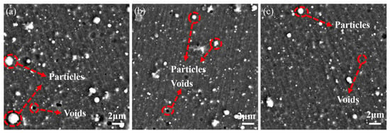
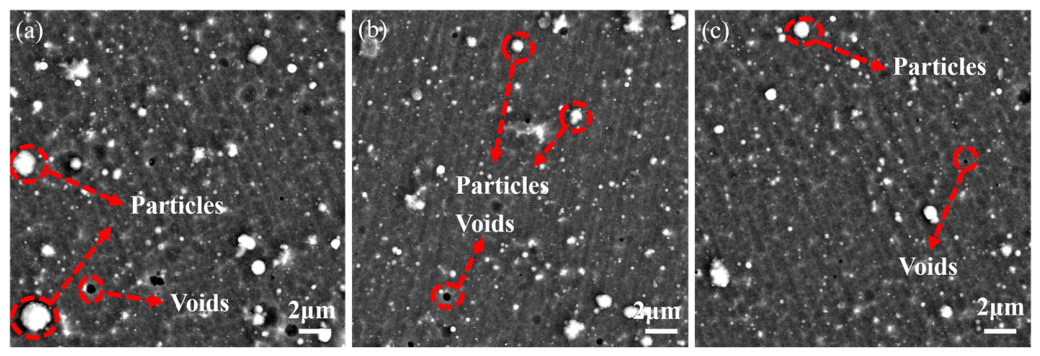
Figure 1 presents the FESEM surface morphologies of the CrN coating, CrAlN coating, and CrN/CrAlN multilayer coating deposited by arc ion plating. All three coatings exhibit relatively dense microstructures; however, a small number of micropores (voids) and particulate defects (Particles) are observable on each surface. The formation of micropore defects is attributed to gas entrapment caused by arc spot instability during the AIP deposition process, while the granular protrusions originate from macroparticle deposition generated by micro-arc discharge events on the target surface during arc evaporation, which is an inherent characteristic of arc ion plating [18]. The CrN coating (Figure 1a) displays a comparatively higher density of micropores with larger dimensions, accompanied by a notable distribution of granular protrusions. The CrAlN coating (Figure 1b) shows a reduced surface defect density relative to the CrN coating, with smaller micropore sizes and fewer particulate features, indicating that the incorporation of Al promotes grain refinement and improves coating densification [19]. The surface morphology of the CrN/CrAlN multilayer coating (Figure 1c) is similar to that of the CrAlN coating, with both the number and size of micropores and particulate defects at comparatively low levels, presenting a relatively uniform and dense surface character [20].
Figure 1.
Surface morphology of the coatings observed by scanning electron microscopy (FESEM): (a) CrN, (b) CrAlN, and (c) CrN/CrAlN multilayer coatings.
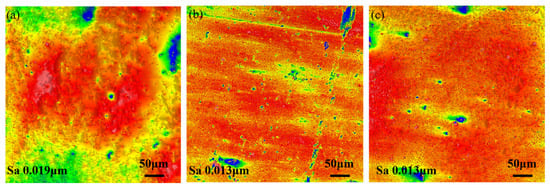
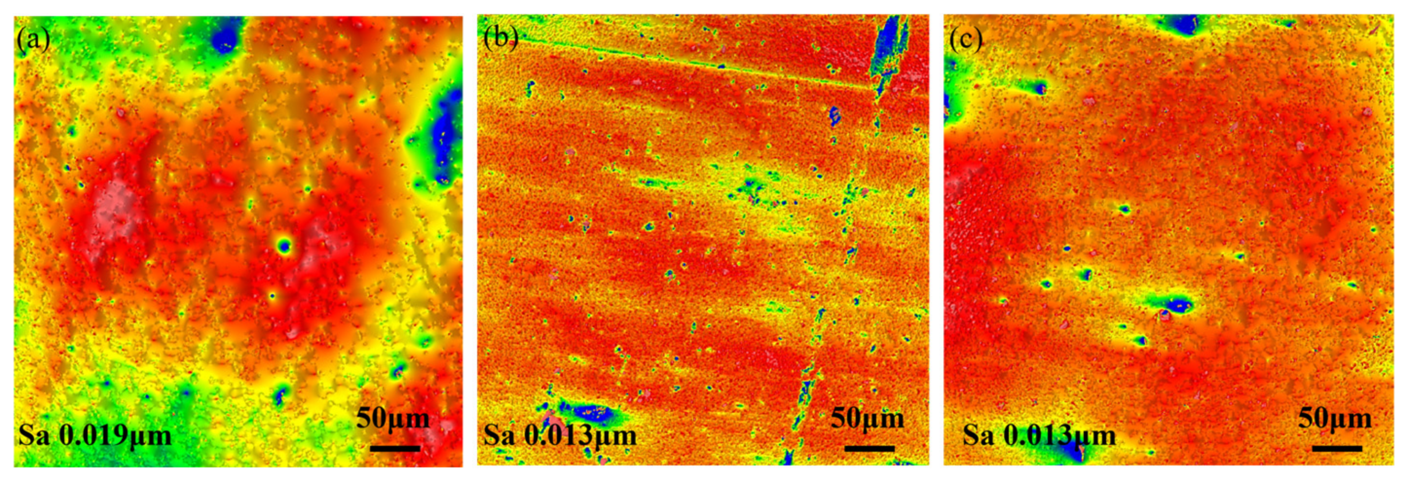
To further compare the surface roughness characteristics of the three coatings, Figure 2 presents the three-dimensional surface morphologies of the coatings measured by white-light interferometry. The CrN coating (Figure 2a) exhibits an arithmetic mean surface roughness, Sa, of 0.019 μm, while both the CrAlN coating (Figure 2b) and the CrN/CrAlN multilayer coating (Figure 2c) yield Sa values of 0.013 μm, lower than that of the CrN coating. The reduced surface roughness of the CrAlN coating and CrN/CrAlN multilayer coating is consistent with the fewer surface defects observed in their FESEM morphologies, further confirming that the addition of Al and the multilayer structural design are beneficial in suppressing macroparticle generation during the AIP process, thereby yielding smoother and more uniform coating surfaces. Lower surface roughness can reduce the severity of surface defects and hinder the penetration of corrosive species, which is beneficial for improving the corrosion resistance of the coatings [21,22].
Figure 2.
Three-dimensional surface topography of the coatings measured by white-light interferometry: (a) CrN, (b) CrAlN, and (c) CrN/CrAlN multilayer coatings.
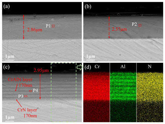
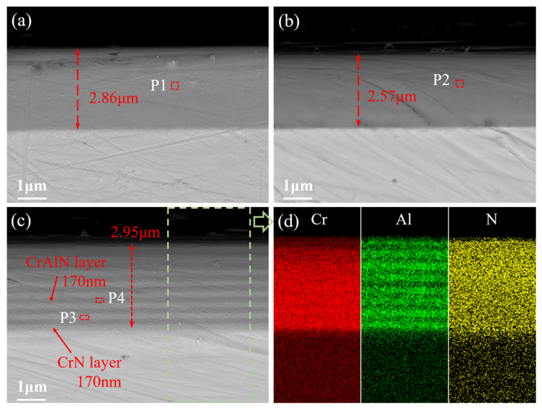
Figure 3 presents the cross-sectional morphologies and elemental distributions of the CrN, CrAlN, and CrN/CrAlN multilayer coatings. As shown in Figure 3a, the CrN coating exhibits a dense and uniform cross-sectional structure with a thickness of approximately 2.86 μm. The cross-section of the CrAlN coating (Figure 3b) is likewise relatively dense, with a thickness of approximately 2.57 μm, slightly less than that of the CrN coating. This difference may be associated with the relatively lower deposition rate of the CrAlN layer compared with CrN layer under similar deposition conditions [23]. In the cross-section of the CrN/CrAlN multilayer coating (Figure 3c), alternating light and dark layered structures are clearly visible, with a total thickness of approximately 2.95 μm; the individual sublayer thicknesses of both the CrAlN and CrN sublayers are approximately 170 nm, indicating good uniformity of the modulation period throughout the multilayer. Figure 3d shows the EDS elemental mapping results of the CrN/CrAlN multilayer coating cross-section. Cr and N are uniformly distributed throughout the coating cross-section, whereas Al exhibits periodic enrichment corresponding to the multilayer architecture, further confirming the alternating arrangement of CrAlN and CrN layers.
Figure 3.
Cross-sectional microstructure and elemental distribution of the coatings: (a) CrN, (b) CrAlN, and (c) CrN/CrAlN multilayer coatings. (d) EDS elemental mapping of Cr, Al, and N in the CrN/CrAlN multilayer coating.
Table 1 lists the EDS compositional analysis results for each coating. In the CrN coating (P1), the atomic ratio of Cr to N is close to the stoichiometric ratio of 1:1, with no Al detected. In the CrAlN coating (P2), the Al/(Cr + Al) atomic ratio is approximately 0.38, indicating that Al has been successfully incorporated into the solid solution within the CrN lattice. The compositions of the CrN sublayer (P3) and CrAlN sublayer (P4) in the CrN/CrAlN multilayer coating are consistent with those of the corresponding single-layer CrN and CrAlN coatings, respectively, demonstrating that each sublayer maintains good compositional independence during deposition and that inter-layer elemental interdiffusion is negligible.
Table 1.
EDS-derived atomic composition of CrN (P1), CrAlN (P2), and individual layers in CrN/CrAlN multilayer coating (P3, P4).
3.2. Phase Structure
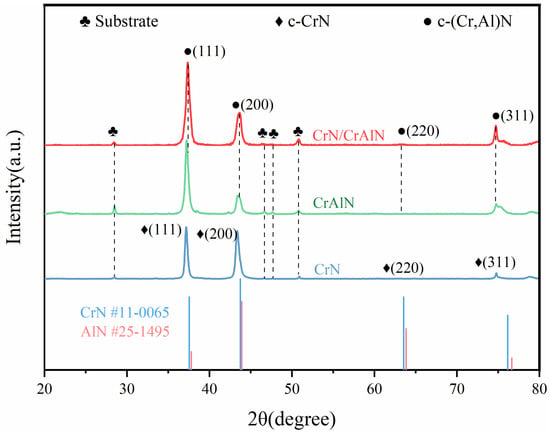
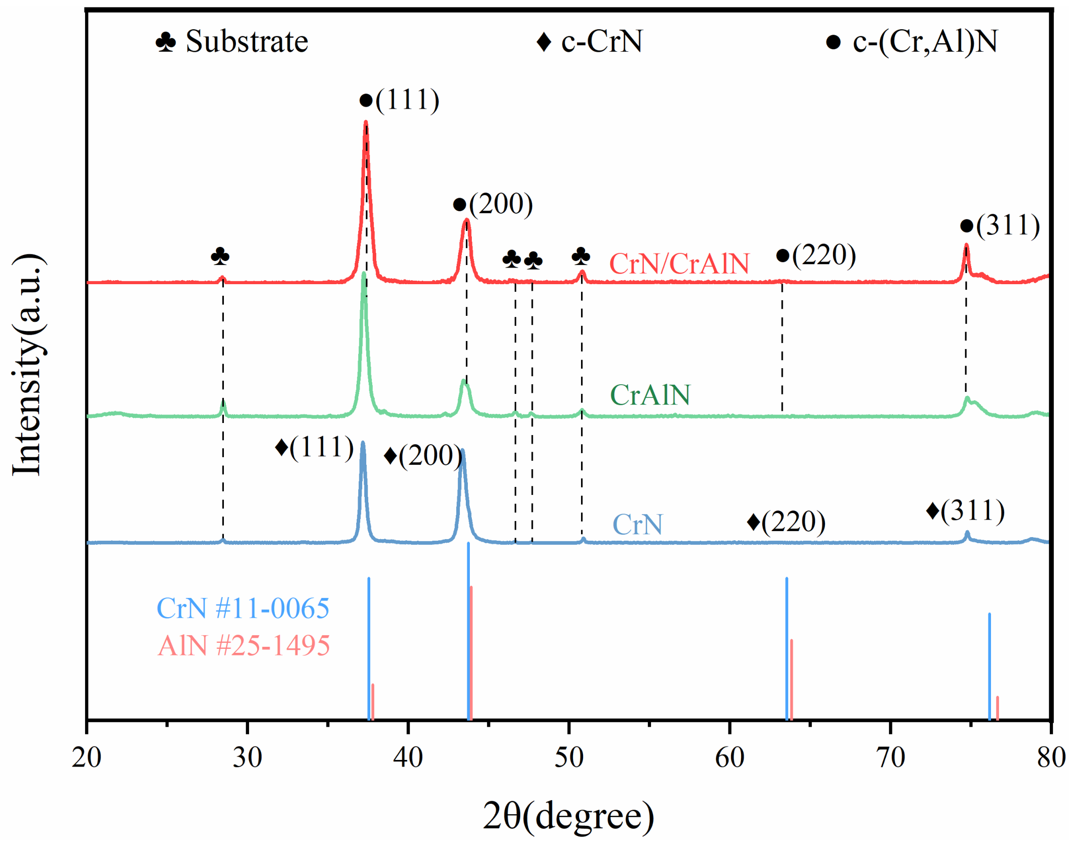
Figure 4 shows the XRD patterns of the CrN coating, CrAlN coating, and CrN/CrAlN multilayer coating. It can be seen that all samples exhibit distinct diffraction peaks at approximately 2θ ≈ 37.3° and 43.5°, corresponding to the (111) and (200) planes of face-centered cubic (FCC) CrN, respectively, while diffraction peaks associated with the (220) and (311) planes are also observed at approximately 2θ ≈ 63.0° and 75.8°. The CrN coating displays only the characteristic diffraction peaks of the FCC-CrN phase, indicating a single-phase cubic CrN structure [24].
Figure 4.
XRD patterns of CrN and CrAlN coatings and CrN/CrAlN multilayer coating.
The diffraction peak positions of the CrAlN coating are similar to those of the CrN coating; however, all peaks are slightly shifted toward higher angles. This shift is attributed to the partial substitution of Cr atoms (0.166 nm) by the smaller Al atoms (0.143 nm), which dissolve into the CrN lattice and reduce the lattice parameter, confirming the formation of an FCC-structured (Cr,Al)N solid-solution phase [25]. Notably, no diffraction peaks corresponding to the hexagonal wurtzite h-AlN phase are detected in the XRD pattern of the CrAlN coating, indicating that at the current Al content, Al atoms are fully incorporated into the CrN lattice, preserving a metastable single-phase FCC-(Cr,Al)N structure [26]. The XRD pattern of the CrN/CrAlN multilayer coating exhibits two sets of diffraction peaks corresponding to c-CrN and c-(Cr,Al)N, with the peaks showing a degree of broadening and overlap, consistent with the alternating layer architecture of CrN and CrAlN in the multilayer structure. In addition, diffraction peaks originating from the substrate are observed in the XRD patterns of all three coatings.
All three coatings exhibit a preferred orientation along the (111) plane, consistent with the characteristic lowest surface energy of the (111) plane in FCC-structured nitride films. Based on the (111) diffraction peaks, the average crystallite size of each coating was calculated using the Scherrer formula [27]. Since instrumental broadening correction was not considered in the present calculation, the reported values are intended mainly for comparative analysis among the samples. The results show that the CrN coating has the largest grain size at approximately 20.27 nm, while the CrAlN coating shows a reduction to 16.22 nm, and the CrN/CrAlN multilayer coating exhibits the smallest grain size of only 13.47 nm. The reduction in grain size of the CrAlN coating can be attributed to the increased lattice distortion induced by the Al solid solution, which enhances nucleation density and thereby suppresses grain growth. The further grain refinement observed in the CrN/CrAlN multilayer coating is related to the periodic interruption of grain growth at the multilayer interfaces: each newly deposited sublayer requires renucleation, which effectively restricts the continuous growth of columnar grains and yields a finer, more uniform grain structure [28]. Grain refinement contributes to improved coating density, which in turn enhances corrosion resistance.
3.3. Friction and Wear
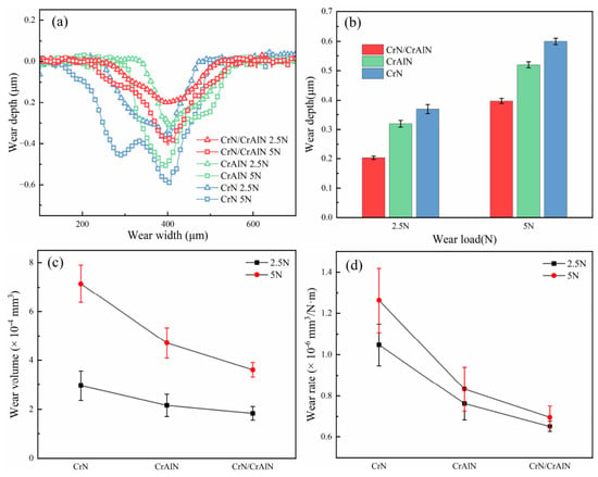
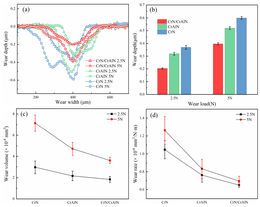
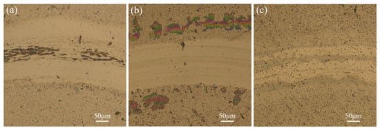
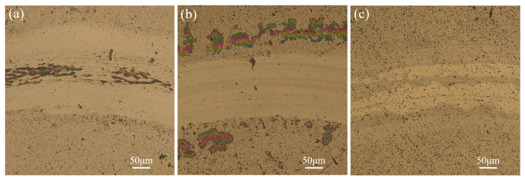
Figure 5 presents the cross-sectional wear profile curves and wear depths of the CrN, CrAlN, and CrN/CrAlN multilayer coatings under loads of 2.5 N and 5 N. As shown in Figure 5a, under identical load conditions, the CrN coating exhibits the widest and deepest wear track, followed by the CrAlN coating, while the CrN/CrAlN multilayer coating shows the shallowest and narrowest wear track. It should be noted that the wear track profile curves of the CrN coating and the CrAlN coating are not completely symmetrical, which may be associated with local non-uniform material removal caused by surface defects and asperity distribution, as well as a slight deviation of the selected profilometry section from the exact wear track center, rather than obvious delamination or spallation of the coatings. As the load increases from 2.5 N to 5 N, the wear track profiles of all three coatings deepen and widen noticeably, with the CrN/CrAlN multilayer coating showing the smallest variation. Combined with the sublayer thickness of approximately 170 nm for the multilayer coating shown in Figure 3c, the wear depth of the CrN/CrAlN multilayer coating under a 2.5 N load is 0.2027 μm, indicating that wear has penetrated through the outermost CrAlN layer and into the second CrN layer. Under a load of 5 N, the wear depth increases to 0.3974 μm, with wear extending further into the third CrN layer; nevertheless, the coating maintains good structural integrity with no delamination or spallation observed, as shown by the worn surface morphology in Figure 6.
Figure 5.
Cross-sectional wear profile curves (a), wear depth (b), wear volume (c), and wear rate (d) of CrN, CrAlN, and CrN/CrAlN multilayer coatings under wear loads of 2.5 N and 5 N.
Figure 6.
Worn surface morphologies of CrN (a), CrAlN (b), and CrN/CrAlN multilayer coatings (c), observed by metallographic microscopy after wear under a load of 5 N.
As is more clearly illustrated in Figure 5b, under both load conditions, the wear depth follows the order CrN > CrAlN > CrN/CrAlN. At a load of 2.5 N, the wear depth of the CrN/CrAlN multilayer coating (0.2027 μm) is significantly lower than that of the CrAlN coating (0.3192 μm) and the CrN coating (0.3686 μm). When the load increases to 5 N, the wear depth of the CrN coating increases to 0.6001 μm and that of the CrAlN coating to 0.5199 μm, while the CrN/CrAlN multilayer coating only reaches 0.3974 μm.
The calculated wear volumes and wear rates follow the same trend as the wear depths [29], as presented in Figure 5c,d. At a load of 2.5 N, the wear volumes of the CrN, CrAlN, and CrN/CrAlN multilayer coatings are 2.96 × 10⁻⁴, 2.16 × 10⁻⁴, and 1.84 × 10⁻⁴ mm3, respectively, and the corresponding wear rates are 1.047 × 10⁻⁶, 7.629 × 10⁻⁷, and 6.516 × 10⁻⁷ mm3/(N·m), respectively. When the load increases to 5 N, the wear volumes increase to 7.14 × 10⁻⁴, 4.71 × 10⁻⁴, and 3.61 × 10⁻⁴ mm3, while the corresponding wear rates increase to 1.262 × 10⁻⁶, 8.331 × 10⁻⁷, and 6.962 × 10⁻⁷ mm3/(N·m), respectively. It should be noted that the wear rate is determined by both wear volume and applied load. Accordingly, different wear rate values are obtained for the same coating under different loading conditions. Under both loading conditions, the CrN/CrAlN multilayer coating exhibits the lowest wear volume and wear rate, indicating the best wear resistance among the three coatings.
3.4. Electrochemical Testing Prior to Wear
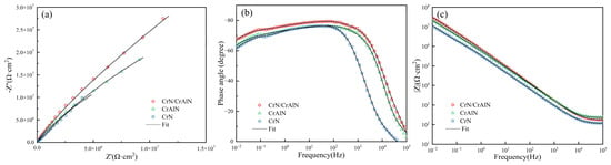
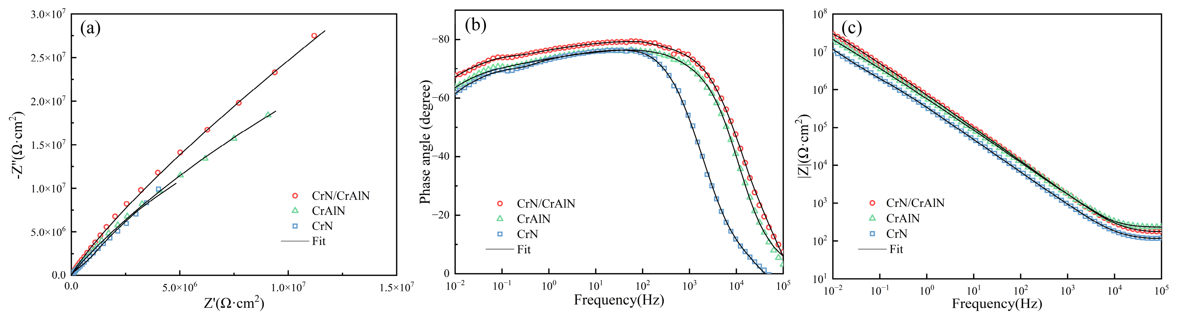
Figure 7 shows the electrochemical impedance spectra of the CrN coating, CrAlN coating, and CrN/CrAlN multilayer coating in a 3.5 wt.% NaCl solution. As observed from the Nyquist plots (Figure 7a), all three coatings exhibit a single capacitive arc, and the radius of the capacitive arc follows the order CrN/CrAlN > CrAlN > CrN. A larger capacitive arc radius indicates a higher charge transfer resistance of the coating and thus better corrosion resistance [30]. The CrN/CrAlN multilayer coating exhibits the largest capacitive arc radius, suggesting that it possesses the best corrosion resistance among the three coatings.
Figure 7.
Comparison of the electrochemical impedance spectra of the CrN coating, CrAlN coating, and CrN/CrAlN multilayer coating: (a) Nyquist plots, (b) phase angle–frequency plots, and (c) impedance modulus–frequency plots.
As shown in the phase angle–frequency plot (Figure 7b), the CrN/CrAlN multilayer coating exhibits the largest phase angle in the low-to-mid-frequency region, with a broader frequency range corresponding to the phase angle peak, indicating a stronger capacitive response and a denser coating structure [31]. As shown in the impedance modulus–frequency plot (Figure 7c), in the low-frequency region, the |Z| values follow the order CrN/CrAlN > CrAlN > CrN. Since the low-frequency |Z| value typically reflects the total impedance of the coating, this further confirms that the CrN/CrAlN multilayer coating possesses the best corrosion resistance among the three coatings.
To further quantitatively analyze the electrochemical behavior of the coatings, the EIS data were fitted using equivalent electrical circuits (Figure 8) [32]. In the present work, the CrN coating and CrAlN coating were fitted using a single-time-constant equivalent circuit model, Rs(CPE1R1) (Figure 8a), where Rs represents the solution resistance, CPE1 denotes the constant phase element of the coating, and R1 corresponds to the coating resistance. Due to the multilayer structural characteristics of the CrN/CrAlN coating, a two-time-constant equivalent circuit model, Rs(CPE1R1)(CPE2R2), was employed (Figure 8b), in which CPE1 and R1 correspond to the outer coating layer, while CPE2 and R2 represent the inner coating layer and the coating/substrate interface.
Figure 8.
Equivalent electrical circuits used for fitting the electrochemical impedance spectra of the CrN coating, CrAlN coating, and CrN/CrAlN multilayer coating: (a) CrN coating and CrAlN coating; (b) CrN/CrAlN multilayer coating.
The fitting results are listed in Table 2. The coating resistance R1 of the CrN coating is 3.49 × 10⁷ Ω·cm2, while that of the CrAlN coating reaches 6.78 × 10⁷ Ω·cm2, which is higher than that of the CrN coating, indicating that the incorporation of Al effectively improves the compactness and corrosion resistance of the coating. The R1 value of the CrN/CrAlN multilayer coating is as high as 1.48 × 10⁸ Ω·cm2, which is significantly higher than those of the CrN and CrAlN coatings, demonstrating that the multilayer structure further enhances the protective performance of the coating. In addition, the CrN/CrAlN multilayer coating exhibits the lowest CPE1 value (3.42 × 10⁻⁷ Ω−1·cm−2·sn) and the highest n value (0.88), indicating that this coating possesses the most uniform and compact surface, and its capacitive behavior is closest to that of an ideal capacitor. The inner-layer resistance R2 of the multilayer coating is 9.10 × 10⁵ Ω·cm2, which further provides an additional corrosion protection barrier for the substrate.
Table 2.
EIS fitting parameters of the CrN coating, CrAlN coating, and CrN/CrAlN multilayer coating in 3.5 wt.% NaCl solution.
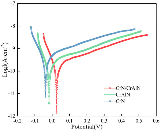
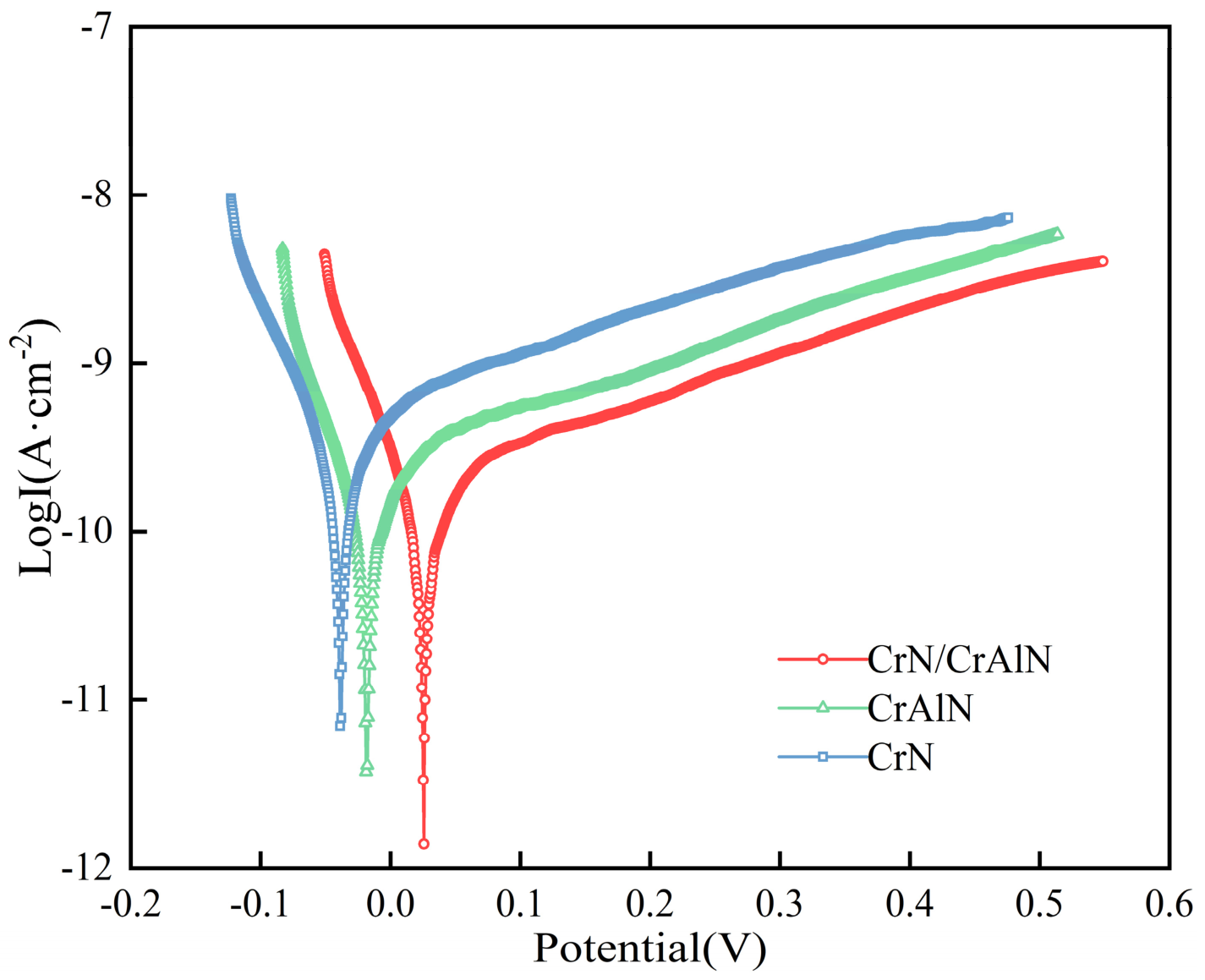
Figure 9 presents the potentiodynamic polarization curves of the CrN coating, CrAlN coating, and CrN/CrAlN multilayer coating in a 3.5 wt.% NaCl solution, and the corresponding electrochemical corrosion parameters are listed in Table 3. As shown in Figure 9, the polarization curves of all three coatings exhibit a certain passivation tendency, indicating that passive film formation occurs on the coating surfaces in the NaCl solution. However, no sufficiently well-defined and stable passive plateau is observed for all samples over a comparable potential range [33]. Therefore, passive current density was not used as a comparative parameter in this study. The polarization curve of the CrN/CrAlN multilayer coating shifts overall toward the lower right compared with those of the CrN and CrAlN coatings, moving toward a lower corrosion current density and a more positive corrosion potential, indicating superior corrosion resistance [15].
Figure 9.
Potentiodynamic polarization curves of the CrN coating, CrAlN coating, and CrN/CrAlN multilayer coating in 3.5 wt.% NaCl solution.
Table 3.
Potentiodynamic polarization parameters of the CrN coating, CrAlN coating, and CrN/CrAlN multilayer coating in 3.5 wt.% NaCl solution.
As shown in Table 3, the corrosion current density (Icorr) of the CrN coating is 5.72 × 10⁻¹⁰ A/cm2, and the corrosion potential (Ecorr) is −0.038 V; for the CrAlN coating, the Icorr decreases to 3.92 × 10⁻¹⁰ A/cm2, while the Ecorr shifts positively to −0.026 V. In contrast, the CrN/CrAlN multilayer coating exhibits a further decrease in Icorr to 2.74 × 10⁻¹⁰ A/cm2 and a positive shift in Ecorr to 0.025 V. Compared with the single CrN coating, the multilayer structure presents a lower corrosion current density and a more positive corrosion potential, indicating that the driving force of the corrosion reaction is reduced and the overall corrosion resistance is improved [34]. These results indicate that, under the same testing conditions, the multilayer structure can suppress the corrosion reaction to a certain extent, thereby further enhancing the corrosion resistance of the coating.
3.5. Electrochemical Testing After Wear
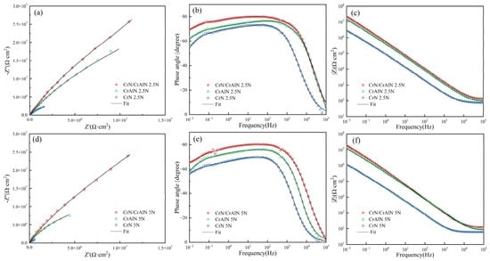
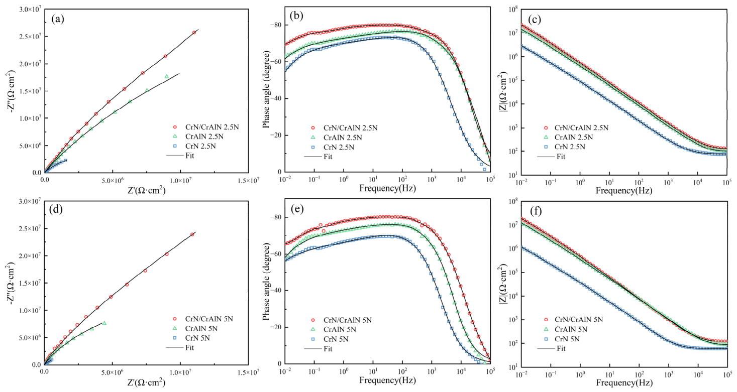
Figure 10 presents the electrochemical impedance spectra (EIS) of the CrN coating, CrAlN coating, and CrN/CrAlN multilayer coating after wear tests under loads of 2.5 N and 5 N. As observed from the Nyquist plots (Figure 10a,d), under both loading conditions, the CrN/CrAlN multilayer coating exhibits the largest capacitive arc radius, followed by the CrAlN coating, while the CrN coating shows the smallest radius, indicating that the CrN/CrAlN multilayer coating still possesses the best electrochemical corrosion resistance after wear. In the Bode phase angle plots (Figure 10b,e), the CrN/CrAlN multilayer coating displays the highest and broadest phase angle peak in the intermediate frequency region, reflecting a more ideal capacitive response and a denser passive film structure on the worn surface [35]. The Bode impedance modulus plots (Figure 10c,f) further demonstrate that the impedance modulus of the CrN/CrAlN multilayer coating in the low-frequency region is significantly higher than that of the other two coatings, which is consistent with the trend observed in the Nyquist plots.
Figure 10.
Comparison of the electrochemical impedance spectra of the CrN coating, CrAlN coating, and CrN/CrAlN multilayer coating after wear tests at different loads: (a,d) Nyquist plots, (b,e) phase angle vs. frequency plots, and (c,f) impedance modulus vs. frequency plots.
Table 4 lists the equivalent circuit fitting parameters of the EIS for each coating after wear. In the present work, the impedance spectra of the CrN coating and CrAlN coating after wear were fitted using a single-time-constant equivalent circuit, whereas the CrN/CrAlN multilayer coating after wear was fitted using a two-time-constant equivalent circuit. This indicates that the multilayer structure maintains a layered corrosion protection mechanism even after wear. Under a load of 2.5 N, the charge transfer resistance R1 of the CrN/CrAlN multilayer coating reaches 1.38 × 10⁸ Ω·cm2, which is markedly higher than those of the CrAlN coating (6.048 × 10⁷ Ω·cm2) and the CrN coating (6.87 × 10⁶ Ω·cm2). When the load increases to 5 N, the R1 values of all three coatings show a decreasing trend, declining to 1.20 × 10⁸, 2.19 × 10⁷, and 3.05 × 10⁶ Ω·cm2, respectively; however, the CrN/CrAlN multilayer coating still maintains the highest charge transfer resistance. In addition, the CrN/CrAlN multilayer coating exhibits the lowest CPE1 values under both loads (3.56 × 10⁻⁷ and 4.22 × 10⁻⁷ Ω−1·cm−2·sn, respectively), accompanied by the highest dispersion index, na, values (0.86 and 0.90, respectively), indicating that its worn surface is more uniform and compact, and that its interfacial capacitive behavior is closer to that of an ideal capacitor.
Table 4.
EIS fitting parameters of the CrN coating, CrAlN coating, and CrN/CrAlN multilayer coating after wear tests under different loads.
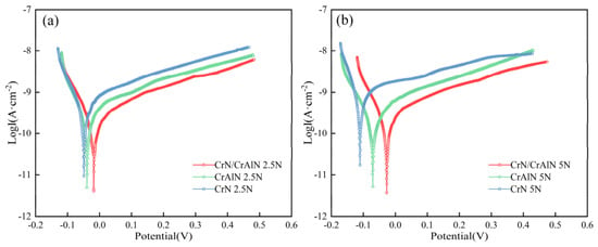
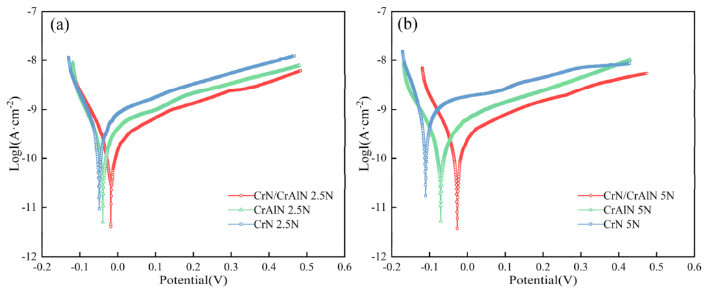
Figure 11 shows the potentiodynamic polarization curves of the three coatings after wear under different loads, and the corresponding electrochemical corrosion parameters are listed in Table 5. Under a load of 2.5 N, the CrN/CrAlN multilayer coating exhibits the lowest corrosion current density (Icorr = 2.83 × 10⁻¹⁰ A/cm2) and the most positive corrosion potential (Ecorr = −0.018 V), indicating the best corrosion resistance among the three coatings. The corrosion parameters of the CrAlN coating are intermediate (Icorr = 4.14 × 10⁻¹⁰ A/cm2 and Ecorr = −0.039 V), whereas the CrN coating exhibits the poorest corrosion resistance (Icorr = 7.73 × 10⁻¹⁰ A/cm2 and Ecorr = −0.048 V).
Figure 11.
Potentiodynamic polarization curves of the CrN coating, CrAlN coating, and CrN/CrAlN multilayer coating after wear under different loads: (a) 2.5 N; (b) 5 N.
Table 5.
Potentiodynamic polarization parameters of the CrN coating, CrAlN coating, and CrN/CrAlN multilayer coating after wear tests under different loads.
When the load increases to 5 N, the corrosion resistance of all three coatings deteriorates to varying degrees. Among them, the CrN coating shows the most pronounced degradation, with its Icorr sharply increasing to 1.36 × 10⁻⁹ A/cm2 and Ecorr shifting markedly in the negative direction to −0.111 V, indicating that severe wear damage under higher load significantly weakens the corrosion protection capability of the CrN coating. The CrAlN coating exhibits a slight increase in Icorr to 4.56 × 10⁻¹⁰ A/cm2 and a negative shift in Ecorr to −0.071 V, demonstrating relatively good load tolerance. In contrast, the CrN/CrAlN multilayer coating shows the smallest variation in corrosion parameters under a load of 5 N (Icorr = 3.35 × 10⁻¹⁰ A/cm2, Ecorr = −0.020 V), exhibiting the best post-wear corrosion resistance among the three coatings [36].
4. Discussion
4.1. Corrosion Resistance of the Multilayer Coating
According to the experimental results, the CrN/CrAlN multilayer coating exhibits the best corrosion resistance among the three coatings in the unworn state, with the lowest corrosion current density (2.74 × 10⁻¹⁰ A/cm2), the most positive corrosion potential (0.025 V), and the highest coating resistance R1 (1.48 × 10⁸ Ω·cm2). This superior corrosion resistance is closely related to the microstructural characteristics of the coating.
As shown in Figure 1 and Figure 2, the CrN/CrAlN multilayer coating exhibits a relatively low density of surface defects, with both micropores and macroparticle defects maintained at a low level, and a surface roughness (Sa) of only 0.013 μm. Micropores and surface defects serve as preferential pathways for the penetration of corrosive media [37]. Therefore, the reduced number of surface defects makes it more difficult for corrosive ions (such as Cl−) to penetrate through the coating surface into the interior of the coating, thereby lowering the probability of localized corrosion. In addition, micropores and cracks can act as locally occluded sites, where chloride ions tend to accumulate and species exchange with the bulk solution is hindered, thereby promoting localized corrosion similar to crevice corrosion. Within the coating, the XRD analysis in Figure 4 indicates that the average grain size of the CrN/CrAlN multilayer coating is only 13.47 nm, which is the smallest among the three coatings. The multilayer interfaces periodically interrupt columnar grain growth, thereby refining and densifying the microstructure while prolonging the diffusion path of corrosive media through the coating [38].
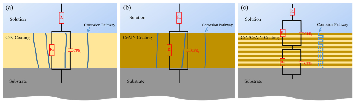
On the basis of the dense coating microstructure, the interfacial effect of the multilayer structure further enhances its corrosion resistance. As shown in Figure 3c, the CrN and CrAlN layers are alternately stacked with a modulation period of approximately 170 nm, forming a large number of heterogeneous interfaces. These interfaces effectively interrupt the continuous propagation of through-thickness defects such as columnar grain boundaries and microcracks, forcing the corrosion medium to undergo repeated path deflection during penetration and thereby significantly extending the effective diffusion path for corrosive ions from the coating surface to the substrate (Figure 12) [39]. Figure 12 schematically illustrates the corrosion pathways in the CrN coating, CrAlN coating, and CrN/CrAlN multilayer coating, highlighting the barrier effect of the multilayer interfaces against the penetration of corrosive media. This multiple-barrier effect is also confirmed by the EIS analysis: fitting of the CrN/CrAlN multilayer coating requires a two-time-constant equivalent circuit (Figure 8b), indicating that the outer and inner layers function as independent corrosion protection barriers.
Figure 12.
Schematic illustration of corrosion pathways and barrier effect in (a) CrN coating, (b) CrAlN coating, and (c) CrN/CrAlN multilayer coating.
4.2. Effect of Wear on Corrosion Resistance
In the unworn condition, the corrosion resistance of a coating mainly depends on the integrity and barrier effect of its continuous surface structure, whereas after wear, the residual protective capacity is governed by whether the damaged region can still impede the penetration of corrosive species. For the CrN/CrAlN multilayer coating, although part of the outer layer is removed during wear, the remaining multilayer architecture still maintains a more tortuous diffusion path and interfacial blocking effect, thereby contributing to its superior post-wear corrosion resistance. Compared with the unworn condition, all three coatings showed deterioration in corrosion resistance after wear, but the extent of degradation was markedly different. For the CrN coating, Icorr increased from 5.72 × 10⁻¹⁰ A/cm2 before wear to 1.36 × 10⁻⁹ A/cm2 after wear under 5 N, while Ecorr shifted from −0.038 V to −0.111 V. For the CrAlN coating, Icorr increased from 3.92 × 10⁻¹⁰ to 4.56 × 10⁻¹⁰ A/cm2, accompanied by a negative shift in Ecorr from −0.026 V to −0.071 V. In contrast, the CrN/CrAlN multilayer coating showed the smallest variation, with Icorr changing only from 2.74 × 10⁻¹⁰ to 3.35 × 10⁻¹⁰ A/cm2, while Ecorr shifted from 0.025 V to −0.020 V. A similar trend was observed in the EIS fitting results: the R1 value of the CrN/CrAlN multilayer coating remained as high as 1.20 × 10⁸ Ω·cm2 after wear under 5 N, whereas the corresponding values for the CrAlN and CrN coatings decreased to 2.19 × 10⁷ and 3.05 × 10⁶ Ω·cm2, respectively.
The reduction in corrosion resistance after wear is mainly associated with wear-induced microcracks and local surface damage, which weaken the continuity of the protective layer and facilitate the ingress of corrosive media, rather than with the total coating thickness alone [39,40].
The CrN coating exhibits the most severe corrosion degradation after wear (Figure 5). Under a load of 5 N, the wear depth reaches 0.6001 μm, corresponding to a thickness loss of approximately 21% of the coating. As a single-phase FCC-CrN structure, the CrN coating lacks heterogeneous interfaces to impede crack propagation, so wear-induced microcracks readily propagate along columnar grain boundaries, forming through-thickness corrosion pathways. This explains the sharp increase in Icorr to 1.36 × 10⁻⁹ A/cm2 and the negative shift in Ecorr to −0.111 V under the 5 N load (Table 5), indicating that the integrity of the coating’s barrier has been severely compromised.
The corrosion degradation of the CrAlN coating falls between that of the CrN coating and the CrN/CrAlN multilayer coating. As the load increases from 2.5 N to 5 N, R1 decreases from 6.048 × 10⁷ to 2.19 × 10⁷ Ω·cm2, while Icorr only increases slightly from 4.14 × 10⁻¹⁰ to 4.56 × 10⁻¹⁰ A/cm2 (Table 4 and Table 5). This asymmetric change indicates that wear under higher loads weakens the physical barrier, but the chemical stability of the FCC-(Cr,Al)N solid solution partially mitigates the increase in corrosion rate [41]. In addition, the finer and denser grain structure of CrAlN increases the tortuosity of crack propagation paths, delaying the formation of through-thickness corrosion channels [10]. Nevertheless, the significant decrease in R1 under the single-layer structure demonstrates that chemical stability alone cannot fully compensate for the damage to the physical barrier.
The CrN/CrAlN multilayer coating demonstrates excellent wear resistance. Under a 2.5 N load, wear penetrates the top CrAlN layer down to the second CrN layer (wear depth 0.2027 μm); under a 5 N load, it extends to the third CrN layer (wear depth 0.3974 μm). Even with partial removal of the top layer, R1 of the CrN/CrAlN multilayer coating remains at 1.20 × 10⁸ Ω·cm2 after wear under a 5 N load, and Icorr increases only slightly to 3.35 × 10⁻¹⁰ A/cm2, indicating minimal changes in corrosion parameters (Table 4 and Table 5). This stability originates from the heterogeneous interfaces within the multilayer structure, which can deflect and blunt wear-induced cracks, suppress through-thickness propagation, and thus reduce the formation of continuous corrosion pathways [42]. The EIS fitting still requires a two-time-constant equivalent circuit (Table 4), confirming that the remaining multilayer structure maintains a layered corrosion protection mechanism.
A comparison of the responses of the three coatings under different loads indicates that load sensitivity is closely related to their microstructural characteristics. The CrN coating, lacking both interfacial barriers and chemical stability, is the most sensitive to load variations. The CrAlN coating, benefiting from its chemical stability, exhibits relatively good tolerance, but its single-layer structure limits the effectiveness of its physical barrier. In contrast, the CrN/CrAlN multilayer coating combines interfacial barriers with chemical stability, and the synergy between these two factors ensures that effective corrosion protection is maintained in the post-wear condition, demonstrating outstanding post-wear corrosion resistance.
The present results were also compared with those reported by other authors. For single-layer coatings, Zeng et al. [43] reported that a CrAlN coating prepared at a bias voltage of −150 V exhibited a corrosion current density of 3.255 × 10⁻⁶ A/cm2. In the present work, the CrAlN coating showed a much lower Icorr of 3.92 × 10⁻¹⁰ A/cm2 in the unworn state, indicating superior corrosion resistance under the present deposition and testing conditions. For multilayer coatings, Soleimani et al. [44] reported an initial Icorr of 5.7 × 10⁻⁸ A/cm2 for a CrN/CrAlN coating in a 3.5 wt.% NaCl solution, whereas the unworn CrN/CrAlN multilayer coating in the present work exhibited a lower Icorr of 2.74 × 10⁻¹⁰ A/cm2. These comparisons indicate that the coatings prepared in the present work exhibited favorable initial corrosion resistance, and that the multilayer architecture provided the best overall electrochemical protection among the three coatings.
5. Conclusions
In this study, single-layer CrN and CrAlN coatings, as well as a CrN/CrAlN multilayer coating, were deposited on a stainless-steel substrate using arc ion plating. The microstructure, tribological behavior, and electrochemical corrosion performance before and after wear were systematically investigated, and the following conclusions were drawn:
- Compared with the single-layer CrN and CrAlN coatings, the CrN/CrAlN multilayer coating exhibits the finest grains (13.47 nm), the lowest density of surface defects, and the smoothest surface, with a roughness of Sa = 0.013 μm.
- The CrN/CrAlN multilayer coating exhibits the lowest wear under both 2.5 N and 5 N loads, demonstrating superior wear resistance compared to the single-layer coatings. Its periodic heterogeneous interfaces effectively inhibit crack propagation, helping to maintain structural integrity.
- In the unworn state, the CrN/CrAlN multilayer coating exhibits the lowest corrosion current density (2.74 × 10⁻¹⁰ A/cm2), the most positive corrosion potential (0.025 V), and the highest coating resistance (1.48 × 10⁸ Ω·cm2), indicating superior corrosion resistance.
- After wear, the CrN/CrAlN multilayer coating still maintains a high charge transfer resistance of 1.20 × 10⁸ Ω·cm2 under a 5 N load. Even when the wear track penetrates several sublayers, the multilayer coating remains intact without obvious delamination and preserves effective post-wear corrosion protection, demonstrating the practical advantage of the multilayer architecture under mechanically damaged conditions.
Author Contributions
Conceptualization, W.L.; Methodology, S.Z., W.C. and H.L.; Validation, S.Z., W.C. and M.J.; Formal analysis, S.Z., R.Y., H.L. and L.Z.; Investigation, S.Z., W.C. and R.Y.; Resources, W.L. and X.S.; Data curation, W.C.; Writing—original draft preparation, S.Z., W.L. and M.J.; Writing—review and editing, R.Y., L.Z., H.L., W.L., M.J. and X.S.; Supervision, W.L., M.J. and X.S.; Funding acquisition, W.L. and M.J. All authors have read and agreed to the published version of the manuscript.
Funding
This work was supported by the National Key Research and Development Program of China (2024YFB3214001), the “Minjiang Scholarship” program of Fujian Province and open funding by the National–Local Joint Engineering Research Center for Industrial Friction and Lubrication Technology (2024GD004) and High-Level Talents Support of Xiamen University of Technology (YKJ22056R).
Data Availability Statement
The original contributions presented in the study are included in the article, further inquiries can be directed to the corresponding author.
Conflicts of Interest
The authors declare no conflicts of interest.
Abbreviations
The following abbreviations are used in this manuscript:
| AIP | Arc Ion Plating |
| PVD | Physical Vapor Deposition |
| OCP | Open-Circuit Potential |
| EIS | Electrochemical Impedance Spectroscopy |
| SCE | Saturated Calomel Electrode |
| FESEM | Field Emission Scanning Electron Microscopy |
| EDS | Energy-Dispersive Spectroscopy |
| SE2 | Secondary Electron Detector |
| HDBSD | High-Definition Backscattered Electron Detector |
| XRD | X-Ray Diffraction |
| FCC | Face-Centered Cubic |
| hcp | Hexagonal Close-Packed |
| CPE | Constant Phase Element |
References
- Kappenthuler, S.; Seeger, S. Holistic evaluation of the suitability of metal alloys for sustainable marine construction from a technical, economic and availability perspective. Ocean Eng. 2021, 219, 108378. [Google Scholar] [CrossRef] [Scilit]
- Nazir, M.H.; Khan, Z.A.; Saeed, A.; Siddaiah, A.; Menezes, P.L. Synergistic wear-corrosion analysis and modelling of nanocomposite coatings. Tribol. Int. 2018, 121, 30–44. [Google Scholar] [CrossRef] [Scilit]
- Zhang, Y.P.; Wang, Z.; Zhang, Y.L.; Li, L.; Guo, P.; Wang, A.Y. Unraveling corrosion and tribocorrosion mechanisms of stainless steel in chloride/bromide media: The dual role of corrosion products. Corros. Sci. 2026, 262, 113643. [Google Scholar] [CrossRef] [Scilit]
- Alkan, S.; Gök, M.S. Effect of sliding wear and electrochemical potential on tribocorrosion behaviour of AISI 316 stainless steel in seawater. Eng. Sci. Technol. Int. J. 2021, 24, 524–532. [Google Scholar] [CrossRef] [Scilit]
- Dalibón, E.L.; Abreu-García, A.; Maskavizan, A.J.; Izquierdo, J.; Souto, R.M.; Brühl, S.P. Wear and corrosion behavior of AISI 420 stainless steel coated with PVD AlCrN. Surf. Coat. Technol. 2026, 522, 133182. [Google Scholar] [CrossRef] [Scilit]
- Li, H.; Zhang, C.; Liu, C.; Huang, M.D. Improvement in corrosion resistance of CrN coatings. Surf. Coat. Technol. 2019, 365, 158–163. [Google Scholar] [CrossRef] [Scilit]
- Liu, Y.K.; Yang, Y.; Liu, X.G.; Zheng, J.; Zhang, S.H. Tribocorrosion of CrN coatings on different steel substrates. Surf. Coat. Technol. 2024, 484, 130829. [Google Scholar] [CrossRef] [Scilit]
- Cedeño-Vente, M.L.; Manríquez, J.; Mondragón-Rodríguez, G.C.; Camacho, N.; Gómez-Ovalle, A.E.; Gonzalez-Carmona, J.M.; Alvarado-Orozco, J.M.; Espinosa-Arbelaez, D.G. Application of a transmission line model to evaluate the influence of structural defects on the corrosion behavior of arc-PVD CrN coatings. Ceram. Int. 2021, 47, 20885–20899. [Google Scholar] [CrossRef] [Scilit]
- Cao, H.S.; Yang, J.; Li, Y.H.; Ren, L.Y.; Qi, F.G.; Zhao, N.; Zhou, Y.; Li, B.B.; Ouyang, X.P. Effect of nitrogen pressure on the microstructure, mechanical and electrochemical properties of CrAlN coatings deposited by filter cathode vacuum arc. Ceram. Int. 2022, 48, 36570–36584. [Google Scholar] [CrossRef] [Scilit]
- Xu, X.; Li, W.F.; Wan, B.B.; Jin, S.X.; Chen, K.; Su, F.H. Extremely improved the corrosion resistance and anti-wear behavior of aluminum alloy in 3.5% NaCl solution via amorphous CrAlN coating protection. Corros. Sci. 2024, 230, 111952. [Google Scholar] [CrossRef] [Scilit]
- Fan, Q.X.; Zhang, J.J.; Wu, Z.H.; Liu, Y.M.; Zhang, T.; Yan, B.; Wang, T.G. Influence of Al content on the microstructure and properties of the CrAlN coatings deposited by arc ion plating. Acta Metall. Sin. (Engl. Lett.) 2017, 30, 1221–1230. [Google Scholar] [CrossRef] [Scilit]
- Liu, Y.R.; Ma, G.S.; Ma, X.; Li, H.; Guo, P.; Wang, A.Y.; Ke, P.L. Corrosion and tribocorrosion performance degradation mechanism of multilayered graphite-like carbon (GLC) coatings under deep-sea immersion in the western Pacific. Corros. Sci. 2024, 239, 112418. [Google Scholar] [CrossRef] [Scilit]
- Cai, F.; Zhou, Q.; Chen, J.K.; Zhang, S.H. Effect of inserting the Zr layers on the tribo-corrosion behavior of Zr/ZrN multilayer coatings on titanium alloys. Corros. Sci. 2023, 213, 111002. [Google Scholar] [CrossRef] [Scilit]
- Vengesa, Y.; Fattah-Alhosseini, A.; Elmkhah, H.; Imantalab, O.; Keshavarz, M.K. Investigation of corrosion and tribological characteristics of annealed CrN/CrAlN coatings deposited by CAE-PVD. Ceram. Int. 2023, 49, 3016–3029. [Google Scholar] [CrossRef] [Scilit]
- Mani, S.P.; Agilan, P.; Kalaiarasan, M.; Ravichandran, K.; Rajendran, N.; Meng, Y.G. Effect of multilayer CrN/CrAlN coating on the corrosion and contact resistance behavior of 316L SS bipolar plate for high temperature proton exchange membrane fuel cell. J. Mater. Sci. Technol. 2022, 97, 134–146. [Google Scholar] [CrossRef] [Scilit]
- Ghorbani, A.; Elmkhah, H.; Imantalab, O.; Meghdari, M.; Nouri, M.; Fattah-Alhosseini, A. The impact of mechanical post-treatment on the tribological and corrosion behavior of CrN/CrAlN coatings applied using the CAE-PVD technique. Appl. Surf. Sci. Adv. 2023, 18, 100477. [Google Scholar] [CrossRef] [Scilit]
- Kılınç, B.; Kocaman, E.; Şen, Ş.; Şen, U. Dry Sliding Wear Behavior of Cr-Al-N Diffusion Coatings against Silicon Nitride. J. Mater. Eng. Perform. 2021, 30, 2113–2123. [Google Scholar] [CrossRef] [Scilit]
- Bobzin, K.; Kalscheuer, C.; Möbius, M.P. Triboactive CrAlN+MoWS coatings deposited by pulsed arc PVD. Surf. Coat. Technol. 2023, 475, 130178. [Google Scholar] [CrossRef] [Scilit]
- Bai, X.; Li, Y.; Guo, C.; Man, J.; Zhang, D.; Wan, Y.; Sun, H. Electrochemical corrosion and tribocorrosion behavior of CrN and CrAlN coatings in artificial seawater. Int. J. Appl. Ceram. Technol. 2024, 21, 3569–3582. [Google Scholar] [CrossRef] [Scilit]
- Arab Baseri, N.; Mohammadi, M.; Ghatee, M.; Abassi-Firouzjah, M.; Elmkhah, H. The effect of duty cycle on the mechanical and electrochemical corrosion properties of multilayer CrN/CrAlN coatings produced by cathodic arc evaporation. Surf. Eng. 2021, 37, 253–262. [Google Scholar] [CrossRef] [Scilit]
- Xu, C.; Ma, S.; Fan, H.; Su, B. Effect of H13 Surface Roughness on the Microstructure and Initial Corrosion Behavior of CrAlN Coatings. Materials 2026, 19, 1005. [Google Scholar] [CrossRef] [Scilit]
- Wang, M.Q. Influence of surface roughness on the anticorrosion performance of plasma sprayed amorphous coating and its electrochemical evaluation. Int. J. Electrochem. Sci. 2023, 18, 100326. [Google Scholar] [CrossRef] [Scilit]
- de Castilho, B.C.N.M.; de Sousa Mazuco, F.; Rodrigues, A.M.; Avila, P.R.T.; Apolinario, R.C.; Daum, P.; da Costa, F.P.; Menezes, R.R.; de Araújo Neves, G.; Greiner, C.; et al. Tailoring the Hybrid Magnetron Sputtering Process (HiPIMS and dcMS) to Manufacture Ceramic Multilayers: Powering Conditions, Target Materials, and Base Layers. Nanomaterials 2022, 12, 2465. [Google Scholar] [CrossRef] [Scilit]
- Huang, X.; Wang, F.; Zhang, Y.; Cui, X.; Zhang, G.; Luo, S. The electrified tribological behavior and mechanism of CrN coating under lubricated conditions. J. Mater. Res. Technol. 2025, 39, 7082–7094. [Google Scholar] [CrossRef] [Scilit]
- Chua, L.L.; Mat Yajid, M.A.; Tamin, M.N.; Kamarudin, M.; Taib, M.A.A.; Nosbi, N.; Ali, W.F.F.W. Effect of substrate roughness and PVD deposition temperatures on hardness and wear performance of AlCrN-coated WC-Co. Surf. Coat. Technol. 2022, 436, 128304. [Google Scholar] [CrossRef] [Scilit]
- Bouamerene, M.S.; Atmani, T.D.; Aissani, L.; Nouveau, C.; Belgroune, A.; Aknouche, H. Optimizing CrAlN coatings: Effects of deposition temperature on mechanical, tribological, and wettability properties. Mater. Today Commun. 2025, 42, 111347. [Google Scholar] [CrossRef] [Scilit]
- Aktarer, S.M.; Sert, Y.; Küçükömeroğlu, T. Investigation of structural, hardness, adhesion, and tribological properties of CrN and AlCrN coatings deposited on cylinder liner. Mater. Des. 2025, 253, 113972. [Google Scholar] [CrossRef] [Scilit]
- Bartosik, M.; Keckes, J.; Persson, P.O.; Riedl, H.; Mayrhofer, P.H. Interface controlled microstructure evolution in nanolayered thin films. Scr. Mater. 2016, 123, 13–16. [Google Scholar] [CrossRef] [Scilit]
- Jin, J.J.; Zhang, Z.Y.; Chen, B.; Wu, X.Y.; Qiu, F.F.; Fu, Z.H.; Chen, W.J.; Gou, G.Q. Effects of hydrogen on the fretting wear behavior of laser cladded FeCoCrNiMo0.2 high entropy alloy coating. Wear 2025, 560–561, 205587. [Google Scholar] [CrossRef] [Scilit]
- Xu, J.; Peng, S.; Li, Z.Y.; Jiang, S.Y.; Xie, Z.H.; Munroe, P. The influence of semiconducting properties of passive films on the cavitation erosion resistance of a NbN nanoceramic coating. Ultrason. Sonochem. 2021, 71, 105406. [Google Scholar] [CrossRef] [Scilit]
- Liao, L.Y.; Wan, Q.; Wang, H.B.; Yang, B.; Mei, Q.S. Irradiation enhanced corrosion resistance of CrN/TiSiN multilayers synthesized by cathodic arc ion plating. Mater. Today Commun. 2023, 35, 106155. [Google Scholar] [CrossRef] [Scilit]
- Lazanas, A.C.; Prodromidis, M.I. Electrochemical Impedance Spectroscopy—A Tutorial. ACS Meas. Sci. Au 2023, 3, 162–193. [Google Scholar] [CrossRef] [Scilit]
- Ahuir-Torres, J.I.; Al-Mahdy, A.; Sharp, M.C.; Opoz, T.T.; Zhu, G.; Bashir, M.; Kotadia, H.R. The influence of texture density and free surface energy on the corrosion resistance of laser-textured 316L stainless steel. npj Mater. Degrad. 2025, 9, 115. [Google Scholar] [CrossRef] [Scilit]
- Li, M.; Yu, Y.; Zou, C.; Tian, C.; Xiang, Y. Tribological and Corrosion Performance of CrAlN/CrN Coatings in Artificial Seawater under Varied Nitrogen Pressures. Coatings 2023, 13, 2090. [Google Scholar] [CrossRef] [Scilit]
- Ji, L.H.; Zhang, J.B.; Lu, Z.B.; Zhou, S.G. Experimental and theoretical investigations of the corrosion barrier of CrN/CrSiN/CrAlN hard coatings. Vacuum 2025, 233, 113968. [Google Scholar] [CrossRef] [Scilit]
- Liu, Y.K.; Lu, Y.Y.; Yang, Y.; Zheng, J.; Zhang, S.H. Effect of different Si content on tribocorrosion performance of CrN/CrSiN multilayer coatings. Surf. Sci. Technol. 2026, 4, 8. [Google Scholar] [CrossRef] [Scilit]
- Wang, Y.X.; Zhang, J.W.; Zhou, S.G.; Wang, Y.C.; Wang, C.T.; Wang, Y.X.; Sui, Y.F.; Lan, J.B.; Xue, Q.J. Improvement in the tribocorrosion performance of CrCN coating by multilayered design for marine protective application. Appl. Surf. Sci. 2020, 528, 147061. [Google Scholar] [CrossRef] [Scilit]
- Lv, Y.J.; Luo, Q.M.; Gu, G.S.; Li, Y.J.; Sun, W.Q.; Gao, J.P.; Liu, M.X.; Meng, Y.; Ma, F. Interfacial effect and hydrogen spillover enhanced anti-corrosion properties of (Pt-)TaN/Ta multi-layer coatings. Surf. Interfaces 2025, 78, 108100. [Google Scholar] [CrossRef] [Scilit]
- Chen, K.; He, T.; Du, X.Y.; Vereschaka, A.; Sotova, C.; Ding, Y.; Li, J. Corrosion Resistance of Ti/Cr Gradient Modulation Period Nanomultilayer Coatings Prepared by Magnetron Sputtering on 7050 Aluminum Alloy. Inorganics 2025, 13, 242. [Google Scholar] [CrossRef] [Scilit]
- Lin, Y.F.; Li, Z.Y.; Wang, X.Q.; Liu, X.; Chi, J.H.; Zhang, Z.H. Effect of Coating Damage on the Micro Area Corrosion Performance of HDR Duplex Stainless Steel. Coatings 2024, 14, 174. [Google Scholar] [CrossRef] [Scilit]
- Shin, D.H.; Kim, S.J. Effects of oxidation treatment on electrochemical characteristics and interfacial contact resistance of CrAlN-coated metallic bipolar plates for PEMFCs. Appl. Surf. Sci. 2025, 686, 162058. [Google Scholar] [CrossRef] [Scilit]
- Yang, K.; Yan, J.W.; Wang, Q.F.; Ding, J.J.; Xu, Q.D.; Wen, Z.Y.; Lu, C.; Fan, T.X.; Gong, M.; Yin, A.Y. Revealing microstructure and the associated corrosion mechanism of Al/amorphous Al2O3/Al tri-layer coating deposited on depleted uranium by magnetron sputtering. Appl. Surf. Sci. 2024, 659, 159911. [Google Scholar] [CrossRef] [Scilit]
- Zeng, P.; Qiu, Z.G.; Wang, G.; Zheng, Z.G.; Zhou, Q.; Liao, X.F.; Zeng, D.C.; Huang, J.B. Enhanced corrosion resistance of NdFeB magnets via arc ion plated CrAlN coatings: Microstructure optimization and property evaluation. J. Alloy. Compd. 2025, 1031, 180921. [Google Scholar] [CrossRef] [Scilit]
- Soleimani, M.; Fattah-Alhosseini, A.; Elmkhah, H.; Babaei, K.; Imantalab, O. A comparison of tribological and corrosion behavior of PVD-deposited CrN/CrAlN and CrCN/CrAlCN nanostructured coatings. Ceram. Int. 2023, 49, 5029–5041. [Google Scholar] [CrossRef] [Scilit]



Disclaimer/Publisher’s Note: The statements, opinions and data contained in all publications are solely those of the individual author(s) and contributor(s) and not of MDPI and/or the editor(s). MDPI and/or the editor(s) disclaim responsibility for any injury to people or property resulting from any ideas, methods, instructions or products referred to in the content. |
© 2026 by the authors. Licensee MDPI, Basel, Switzerland. This article is an open access article distributed under the terms and conditions of the Creative Commons Attribution (CC BY) license.