


Abstract
Agricultural soil contact components, including ploughshares, rotary blades, and furrow openers, form the active interface between machinery and complex field media. Operating in multiphase environments, these tools face severe abrasive wear, impact fatigue, and interfacial adhesion. These destructive forces irreversibly alter edge geometry and drastically degrade macroscopic operation quality. This review integrates tillage and precision seeding components into a unified tribological framework. It highlights the nonlinear relationship between microscopic material removal and geometric edge retention. Profile degradation is heavily dictated by soil texture, where sandy soils cause micro-cutting, clay soils induce severe adhesion, and gravelly soils produce impact fracture. To predict these complex wear behaviours accurately, coupled multiphysics numerical simulation using the discrete element method for particle flow dynamics and finite element analysis for transient contact stress provides a highly robust methodology. Mitigating these failures requires a functionally zoned surface engineering approach. Carbide hardfacing offers localized abrasion resistance, while polymer composite layers and bionic nonsmooth structures effectively interrupt continuous liquid films in wet cohesive soils. Ultimately, integrating online multidimensional sensing with full life cycle digital-twin models represents the future trajectory for developing adaptive and highly durable agricultural equipment.
1. Introduction
Against the macro background of global food security and the rapid development of modern precision agriculture, the operational efficiency and intelligent level of agricultural machinery have become key indicators for evaluating agricultural modernization [1,2]. However, when agricultural machinery operates in complex and variable field media that contain soil, crop residues, and root stubble, its soil contact components remain constrained by physical bottlenecks such as high draft resistance, severe interfacial adhesion, and intense abrasive wear [3,4,5]. Ploughshares, rotary blades, and subsoiler shanks in tillage operations, together with furrow openers, covering devices, and press wheels in precision seeding operations, constitute the core physical interface between machinery and soil [6,7,8]. In multiphase and variable field geological environments, high hardness quartz particles, fluctuating water content, and complex crop residues act jointly and cause unavoidable damage through two-body abrasive wear, three-body abrasive wear, interfacial fatigue, and corrosion-assisted wear. This interfacial failure is prominent, restricts the long-term reliable operation of modern agricultural machinery, and increases fuel consumption and component replacement cost. Studies on the physical mechanisms of friction and wear at soil contact interfaces indicate that a sensitive nonlinear causal relation exists between microscopic material removal and macroscopic operation quality degradation [9,10,11]. At the microscopic scale, abrasive cutting and impact spalling directly change the original geometric configuration of components, which causes edge blunting, cutting angle deviation, and support surface profile loss [12,13,14]. For deep ploughing and soil loosening components, an increase in edge radius changes the contact mechanics model from sharp edge cutting to large area compressive friction, thereby causing a rapid increase in draft force, unstable working depth, and reduced soil inversion and fragmentation quality [15,16,17]. Conventional single material strengthening strategies, such as bulk heat treatment and carburizing quenching, often cannot satisfy the simultaneous requirements of drag reduction, wear resistance, and anti-adhesion performance. Therefore, new pathways must be explored from the perspectives of interface tribology and contact mechanics.
Soil composition and environmental conditions further determine the dominant wear path because the soil–tool interface is a coupled soil–tool–environment system rather than a simple metal–abrasive contact. Recent reviews and field studies show that tool wear is governed jointly by material properties, soil texture, structure, density, moisture, rock and gravel content, and operating dynamics [18]. Granular composition, particle hardness, angularity, and water content control soil abrasivity and cutting edge recession, while field tests on mouldboard ploughshares indicate that moisture can exert a stronger influence on wear than soil type alone, although sandy soils remain highly abrasive because of hard mineral particles [19,20]. In clay-rich soils, the combined effect of water retention, cohesion, and soil–metal adhesion increases frictional resistance and promotes soil film formation, intermittent release, and adhesion-assisted wear [21]. Chemical conditions also need to be considered because wet soil can contain fertilizer salts, organic acids, and dissolved ions that promote corrosion-assisted material removal. When mechanical abrasion repeatedly disrupts protective surface films, corrosion and wear can act synergistically as tribocorrosion; therefore, the degradation of agricultural soil contact components should be evaluated together with moisture, chemistry, corrosion resistance, and surface engineering design [22].
As core cross-scale engineering technologies, the deep integration of surface engineering, digital design, and multiphysics numerical simulation provides a scientific route for overcoming the soil contact bottlenecks of agricultural machinery [23,24,25]. Coupled simulation based on the discrete element method and finite element analysis can reproduce the guiding effect of macroscopic geometry on complex contact stress distribution [26,27]. With these digital tools, researchers can capture particle evolution trajectories in soils with different textures and predict high-risk wear zones [28].
This review aims to provide a systematic account of recent advances in the wear mechanisms, wear-resistant modification technologies, and drag-reduction strategies for agricultural soil contact components [29,30,31]. To avoid a simple enumeration of conclusions from the literature, this study establishes a unified and rigorous analytical framework. Following this logic, tillage components and precision seeding components are placed within the same systematic tribological framework, and the nonlinear governing effects of microscopic material loss and geometric edge retention on macroscopic operation quality degradation are discussed [32,33,34]. This review analyzes the distinct pathways of macroscopic profile degradation driven by sandy soil, clay soil, and gravelly soil, and evaluates the role of coupled discrete element and finite element multiphysics simulation in contact mechanics verification [35,36]. At the engineering application level, thermochemical diffusion, carbide hardfacing, polymer composite anti-adhesion materials, and bionic drag-reduction structures are examined with respect to their technical potential and application boundaries in typical agricultural machinery operations. Finally, this review proposes an integrated development strategy that includes online sensing matrices, deep extraction of characteristic signals, and full life cycle digital-twin prediction models. The purpose is to provide theoretical support for understanding the dynamic evolution of interfaces in extreme multiphase media and to offer a full process design reference for the development of next-generation intelligent agricultural soil contact equipment with low energy consumption and long service life.
2. Wear Evolution and Functional Degradation of Tillage and Seeding Soil Contact Components
2.1. Classification and Working Characteristics of Tillage Soil Contact Components
Tillage soil contact components, as listed in Table 1, include ploughshares, rotary blades, subsoiler shanks, subsoiler sweeps, cultivator sweeps, and replaceable cutting tips. Their common feature is direct execution of soil cutting, turning, mixing, loosening, or shallow cutting. Classification should be based on soil action, load path, contact zone, repairability, and failure index. Ploughshares cut and turn soil through passive wedge action. Rotary blades cut and mix soil through cyclic impact and powered rotation. Subsoiler shanks loosen compacted layers through deep penetration and high-stress sliding. Cultivator sweeps cut shallow soil and weeds through lateral edge contact. These components experience abrasion, impact, adhesion, fatigue, and corrosion-assisted wear, but the dominant mechanism changes with depth, speed, moisture, texture, and residue [37].
Table 1.
Classification, working function, main contact zone, and failure index of tillage soil contact components.
The working chain begins with entry, continues through soil rupture, develops into soil displacement, and ends as field quality. The point, edge, blade tip, or sweep nose converts machine traction into local stress. Soil particles then slide, roll, or impact along the surface and remove material. The guide surface moves soil upward, sideways, backward, or downward. Wear changes each link because geometry loss changes stress concentration and contact direction. Edge rounding changes cutting into compression. Tip recession changes penetration into sliding. Width loss changes full disturbance into incomplete disturbance. Adhesion changes continuous soil flow into intermittent release [38]. Al Neama et al. showed that draft, vertical, and lateral forces arise from passive soil–tool interaction [39]. General studies on tillage depth, draft requirement, tractor power demand, fuel use, tillage objectives, soil structure, working body geometry, and furrow turnover show that ploughshare performance depends on the coupled relation among depth, geometry, energy use, and soil inversion [40,41,42,43]. These findings support a load path view of ploughshare wear. The rear surface may show polishing, but the leading point and edge determine whether soil is cut cleanly or compressed before rupture. Ploughshare classification should therefore distinguish entry zone, slice separation zone, soil guide zone, and rear sliding zone.
Rotary blades represent powered impact cutting and mixing components. Straight blades emphasize slicing, curved blades emphasize cutting and soil throwing, L type blades combine cutting with lateral displacement, and C type blades increase soil holding and mixing. The cutting edge receives impact and abrasion, the guide surface controls particle acceleration, and the root carries cyclic bending and torque. General rotary tillage studies show that vibration exposure, controlled soil bin interaction, and hardened edge response are necessary variables for evaluating rotary blade wear [44,45]. Garibaldi Márquez et al. showed that bio-inspired attack edge geometry can reduce draft force during subsoiling [46]. Subsoiler wear should therefore be described through attack edge form, tip recession, loosened width, draft force, and crack formation. General tillage studies show that depth, tractor speed, implement type, soil texture, validation of draft force models, tine type, tractor ballasting, and conservation tillage goals affect implement behaviour, fuel consumption, force response, and tillage quality [47,48,49,50,51].
2.2. Working Forms and Functional Degradation of Seeding Soil Contact Components
As shown in Table 2, seeding soil contact components include disc openers, covering blades, covering discs, depth wheels, and press wheels. They form a sequential chain. The opener creates the furrow, the seed tube places the seed, the covering device returns soil, and the press wheel compacts the covered furrow. Wear at any point can change seed depth, lateral position, cover thickness, soil seed contact, compaction uniformity, and emergence. The tolerance is stricter than tillage because the output is seed position. Openers must maintain edge sharpness, disc diameter, bevel angle, rake angle, outlet position, and lateral symmetry. Covering devices must maintain soil return trajectory, release timing, and cleanliness. Press wheels must maintain contact width, tread morphology, elastic response, and pressure distribution. Key indices include edge radius in mm, disc diameter loss in mm, tip recession in mm, furrow depth in mm, seed-depth variation in mm, covering thickness in mm, adhesion mass in g, contact pressure in kPa, and emergence rate in percent [52,53,54].
Table 2.
Classification, contact function, wear zone, and sowing quality index of seeding soil contact components.
Karayel et al. showed that opener and disc coulter configuration with residue cover affects seeding depth, spacing, emergence time, and emergence percentage [55]. General studies on opener geometry, machine settings, soil condition, residue condition, disc form, and sowing speed show that no till opener disturbance, force response, placement quality, and seedbed quality are governed by coupled tool and soil variables [56,57,58,59]. Double disc openers are therefore cutting tools and furrow wall forming tools. Diameter loss can reduce furrow depth, bevel change can alter sidewall compression, and soil-adhered surfaces can increase drag. Darmora showed that wedge angle, rake angle, depth, and coarse textured soil affect the draft requirement of shovel type openers [60]. In coarse textured soil, the same geometry change can accelerate lower edge wear. Darmora and Pandey showed that shovel opener geometry affects draft, soil cover, seed scatter, seed fertilizer separation, and row roughness in sandy soil [61]. This study extends wear evaluation from force response to sowing quality. Liang et al. showed that opener tip force measurement can support seeding depth control [62]. Their contact zones are the crown, side edge, groove surface, and tread shoulder. Wet soil can adhere to these surfaces and form deposits. General studies on residue entanglement, opener configuration under cold soil, V-shaped guiding, concave pit furrow geometry, and presowing depth uniformity show that rear chain quality depends on residue flow, furrow geometry, seed displacement control, and preceding depth stability [63,64,65,66]. These factors determine whether press wheel loading produces uniform contact or pressure bands [67,68].
2.3. Tribological Relation Between Wear Rate and Geometric Edge Retention
Wear rate and edge retention form a coupled relation in soil contact components. Wear rate describes material removal per unit time, travel distance, or soil volume, while edge retention describes the capacity of a cutting edge, tip, blade, or disc to keep its designed geometry. The relation is nonlinear because small edge loss can change contact stress, soil rupture mode, sliding distance, and force demand. Ploughshare points, rotary blade edges, subsoiler tips, double disc openers, chisel openers, and covering blades all depend on local geometry. Once edge radius, tip length, or blade width changes, the soil flow path changes and the next wear stage can accelerate [69]. General cutting tool research shows that wear changes cutting quality and promotes the transition from sharp cutting to rounded sliding contact [70]. Zhang et al. showed that tool geometry evolution and wear rate can form positive feedback during cutting (Figure 1) [71]. As Figure 1 displays, the normal stress at the tool tip, expressed by the shear flow stress , was derived through the analysis of the geometric relationships in the slip line field and the equilibrium of force and torque. In this model, J is defined as the chip separation point, while the short edge JU near the tip is considered equivalent to a built-up edge.
Figure 1.
Tool geometry evolution and wear rate [71]. (a) Slip line field of primary shear zone; (b) slip line field velocity vector diagram; (c) geometric relationship diagram of region KJU.
Further studies show that surface microstructure, tool material response, crater formation, and roughness parameters affect wear resistance and cutting stability [72]. These findings support the interpretation that edge radius growth increases soil compression before rupture, raises draft or cutting force, and changes the component from cutting toward ploughing and sliding. For soil tools, this geometric transition is more important than mass loss alone because the leading edge controls the first soil failure boundary.
Tip length controls initial penetration and depth stability. General numerical and experimental studies show that cutting force, tool deflection, wear morphology, wet or dry contact condition, rake angle, speed, and flank wear are coupled with geometry evolution and force response [73,74,75,76,77]. Napiórkowski and Ligier showed that rake angle affects abrasive soil mass wear intensity [78]. Blade and disc width control effective soil disturbance and support the functional meaning of geometric retention. General cutting and coating studies show that crack formation, chipping, cooling condition, lubrication state, coating state, energy demand, surface roughness, temperature, and friction affect wear and force response [79,80,81,82]. These findings support the view that rotary blade width loss reduces mixing width, sweep width loss reduces cutting overlap, disc opener wear reduces furrow support, and covering disc wear reduces backfill control. Geometry loss therefore changes both mechanical load and agronomic function. Kudzaev compared blade shapes of translatory soil tillage tools and showed that blade parameters affect energy demand, residue clogging, and cutting mode [83].
2.4. Soil–Tool–Environment Effects on Wear Evolution and Functional Degradation
The wear evolution of tillage and seeding soil contact components should be interpreted within a soil–tool–environment framework. Soil composition and texture determine the abrasive particle population, including hard minerals, clay aggregates, gravel fragments, organic residues, and entrained third-body particles, whereas moisture and soil–metal interface conditions regulate cohesion, adhesion, particle entrainment, and force transmission [84,85,86]. Therefore, functional degradation is not controlled only by the intrinsic hardness or coating thickness of the component. It emerges from the coupling among soil abrasivity, water-mediated cohesion, operating load, contact scale, and the evolving geometry of the tool surface.
Macroscopic profile degradation depends on soil texture because texture controls mineral hardness, particle shape, particle size, water retention, cohesion, adhesion, and impact probability. Sandy soil tends to produce cutting grooves and edge recession through hard mineral grains. Clay soil tends to produce adhesion-assisted friction, soil film formation, surface polishing, and intermittent release. Gravelly soil tends to produce impact pits, notches, cracks, and local fracture at leading zones. The same component can therefore follow different degradation paths in different fields. A ploughshare may lose its point in sand, carry clay deposits in wet clay, and develop edge notches in gravelly soil. A disc opener may show diameter loss in sand, sidewall smearing in clay, and edge chipping in gravelly soil [87]. Sandy soil promotes micro-cutting because hard grains contact the component surface with limited cohesion and high local stress. Dvoruk showed that abrasive particle shape controls the destruction and wear resistance of structural steels in soil [88]. General impact studies also show that craters, dents, scratches, and fracture influence the profile path in sandy conditions [89].
Han, X—through executing rotary abrasive wear tests on 30MnB5 steel plough tips; regulating moisture (Figure 2), content rotational speed, and friction distance; and measuring wear mass and characterizing microscopic wear morphologies—established that moisture variations drive second order parabolic wear mass changes [90]. Data confirm maximum compressive stress targets plough tips initiating localized material loss. Microscopic analyses define wear mechanisms comprising sand particle embedment groove generation and fatigue spalling pit formation. The observations conclude that damage forms transition from impact wear to groove scratches along soil movement trajectories and abrasive wear synergizes with corrosive wear, accelerating material degradation.
Figure 2.
Macroscopic views of the LK500 high-speed hydraulic turning plough and the plough tip, and three-dimensional wear topographies of the tip surface at friction distances of (a) original surface; (b) 113 km; (c) 226 km; and (d) 339 km [90].
Bal, A.R.L, through constructing Updated Lagrangian Finite Element models, applying Particle Finite Element methods, executing hypoplastic formulations, and performing physical excavation tests (Figure 3), established cutting tool–soft soil interaction mechanisms [91]. Computational results and experimental data characterize free surface topologies as void ratio distributions, reaction force spatiotemporal evolutions, and abrasive wear behaviours. Cucinotta, F analyzed the wear patterns of four ploughshares using a structured blue-light 3D scanner (Figure 4) before and after field usage, applying Hausdorff’s method and deviation analysis to calculate volume losses and profile changes [92]. They concluded that although the wear patterns shared similar shapes, there was significant variability in cutting edge profiles and volume losses, demonstrating that this 3D scanning methodology can easily and effectively evaluate tillage tool wear.
Figure 3.
The experimental setup for the analysis of cutting tool–soil interaction [91].
Figure 4.
Structured blue-light 3D scanner before and after field usage [92].
Ligier et al. showed that moisture content in quartz sand changes abrasive steel wear rate [93]. Additional abrasive process studies show that process type, tool force, power demand, ductility, impact toughness, and steel resistance affect profile degradation in sand-dominated contact [94]. General coating erosion, abrasive particle size, soil conditioning, mineralogy, moisture, and test condition studies show that wet cohesive soil can reduce direct cutting in one zone while increasing adhesion, drag, coating exposure, and local groove formation in another zone [95,96,97,98]. Gravelly soil causes impact fracture because large particles strike leading zones with high local force. General erosion research shows that particle size, velocity, angularity, hardness, toughness, and reinforcing phase control material loss under severe abrasive impact [99]. Wang and Cai showed that Si content and microstructure affect impact the abrasive wear of medium carbon low alloy steels [100]. Ingber et al. showed that abrasive wear can change near-surface microstructure and hardness in metastable austenitic steels [101]. Broader ground-engaging tool and inclusion studies further show that hard particle penetration and inclusion structure can accelerate material loss in impact abrasive contact [102,103].
Environmental effects further change the failure route from pure abrasion to coupled wear–corrosion. In wet or chemically active soils, aqueous films and dissolved ions can alter the transition between dry abrasion, slurry abrasion, and corrosion-assisted material removal [104]. Abrasion repeatedly removes surface films and exposes fresh metal, while corrosion decreases local mechanical resistance and accelerates groove growth, pitting, edge recession, and coating delamination. This tribocorrosion pathway is especially relevant for ploughshare points, subsoiler tips, disc opener edges, and covering or press wheel surfaces that repeatedly pass through wet clay films, saline patches, and residue-rich seedbeds [105]. Future evaluation of soil contact components should therefore report soil texture together with particle-size distribution, mineral hardness, water content, soil–metal adhesion state, chemical condition, corrosion tendency, and wear morphology, so that surface engineering and service-life prediction can be connected to the complete soil–tool–environment system.
3. Soil–Tool Interface Interaction and Multiphysics Simulation of Wear Processes
3.1. Soil Particle Properties and Microscopic Material Removal
Microscopic material removal at agricultural soil contact interfaces originates from discontinuous contacts between mineral particles and working surfaces. Soil is not a uniform abrasive medium. It contains quartz, feldspar, hard rock fragments, clay aggregates, organic residues, roots, water films, and air voids, and each fraction changes stress transmission and sliding behaviour. Quartz and other hard minerals can penetrate steel, carbide reinforced layers, thermochemical diffusion zones, and polymer coatings when local contact pressure exceeds surface resistance. Angular particles generate cutting grooves, lips, pits, and compacted debris, whereas rounded particles tend to polish the surface and reduce the sharpness of local asperities. Consequently, particle mineralogy, hardness, angularity, and size distribution define the abrasive capacity of soil before tool geometry or material design can be assessed [18,106].
In this context, abrasive wear should be interpreted as a load conversion process rather than as simple mass loss. Myalenko modelled tribological processes for abrasive wear of soil cutting parts and linked simulated loading with real soil force equivalents [106]. Furthermore, studies on particle impact velocity, impact angle, grain fracture, particle shape evolution, surface roughness, and multiscale damage indices show that erosion rate, cutting force, and surface quality are controlled by the dynamic state of abrasive particles rather than by particle size alone [107,108,109]. Wear models for agricultural components should therefore include angularity, particle rotation, impact history, contact duration, and roughness evolution.
Moisture content introduces a second mechanism layer because it transforms a loose granular abrasive body into a cohesive friction body. Under low water content, mineral particles contact the material surface directly and promote micro-cutting. At intermediate water content, capillary bonding increases particle retention, strengthens soil aggregates, and extends the residence time of abrasive grains near the surface. Under wet clay conditions, adhesive soil films form on opener flanks, covering devices, press wheels, rotary blade guide surfaces, and ploughshare sliding surfaces. This transition changes wear morphology because adhesion raises drag, shifts the pressure distribution, causes intermittent soil release, and hides the true material surface. Maintenance and weld geometry studies further indicate that mitigation of soil abrasive wear must account for moisture, cohesion, surface relief, and soil flow path [110,111]. Hardfacing strips or repaired overlays may restore hardness but can also trap cohesive soil if their bead geometry interrupts release.
Soil density and compaction then determine the degree of particle confinement. Loose soil permits particles to move away after collision, which limits repeated sliding on the same surface point. Dense or compacted soil traps particles between the working surface and the surrounding soil mass, creating force chains that increase normal stress and deepen grooves. This confinement is severe at subsoiler tips, chisel opener noses, ploughshare points, compacted seedbeds, and press wheel surfaces.
Aleksandra Królicka investigated the wear behaviour of an Fe-Cr-C-Nb system of welded claddings (Figure 5) across hypereutectic, near-eutectic, and hypoeutectic layers under agricultural soil cultivation conditions [112]. They concluded that varying carbide distributions and morphologies cause distinct wear mechanisms across the layers—such as micro-delamination and interdendritic cracking—ultimately leading to a severe “wash-out effect” and significantly reduced tool durability once the cladding is penetrated. Kalcska investigated abrasive wear of polymer and steel gear drives under solid particle contamination with several soil types and showed that resistance depends on particle embedding, scratching, and rolling under confinement, not only on nominal hardness [113]. This analogy is relevant to polymer-coated openers, press wheels, and depth wheels because elastomeric or polymeric surfaces can store abrasive particles during loading and release them during unloading.
Figure 5.
Wear mechanisms and microstructural evolution of Fe-Cr-C-Nb welded claddings under agricultural soil cultivation conditions [114].
Material response closes the microscopic removal sequence. Napirkowski et al. linked abrasive soil wear resistance of Creusabro steel to microstructure and mechanical properties, showing that hardness, toughness, and work hardening must act together under high pressure sliding [114]. Konstanty et al. analyzed the abrasive wear resistance of metallic matrix materials used in diamond-impregnated tools and provided a matrix support analogy for hardfaced ploughshares, subsoiler tips, and opener edges [115].
3.2. Seedbed Soil Interaction and Seeding Component Tribology
Agricultural soil–tool interaction first forms the mechanical boundary conditions of the seedbed through ploughing, rotary tillage, subsoiling, and shallow cultivation. Ploughshares, rotary blades, subsoiler shanks, and cultivator sweeps convert machine power into soil fracture, particle rearrangement, sliding, impact, adhesion, and compaction [39,46]. Their wear changes edge radius, rake angle, flank roughness, local contact area, force direction, and soil flow continuity, so the interface shifts from efficient rupture toward compression and friction. Xu et al. established a spatial measurement method for straw incorporated by rotary tillage and showed that straw distribution after tillage controls heterogeneity in the upper seedbed layer [1]. Guan et al. investigated bionic cutter teeth in secondary soil crushing and demonstrated that reduced soil adhesion and tillage force improve soil fragmentation and surface flow near the working surface [10]. Niu et al. combined experiment and simulation to analyze ditching and backfilling behaviour, and concluded that ditch geometry and backfill stability depend on soil disturbance and soil return paths [15]. Gao et al. used DEM simulation and experiments to study an up-cutting subsoiling method inspired by animal digging, and showed that the attack mode reduces draft by changing soil failure sequence and force transmission [23]. Chen et al. evaluated biomimetic rotary blades and demonstrated that blade geometry affects soil cutting, straw movement, and power demand [116]. Studies on hardened cultivator sweep edges, travel depth uniformity, and abrasive soil impact angle further indicate that blade wear changes effective working width, depth stability, presowing tillage quality, and attack edge persistence [45,78]. Thus, tillage wear influences seeding not only through tool mass loss, but also through clod size, residue bands, compaction strips, loose soil thickness, and opener resistance fluctuation.
Furrow openers, covering devices, and press wheels impose a second contact sequence that converts the inherited seedbed state into furrow geometry, seed position, soil return, and soil seed contact [47,48]. At this stage, working depth is smaller than in primary tillage, but quality tolerance is stricter because small geometry changes can alter furrow depth, lateral seed displacement, covering thickness, contact pressure, and emergence uniformity. Ahmad et al. simulated disc type furrow openers in paddy soil with DEM and showed that particle motion, furrow formation, and tool resistance can be resolved through calibrated contact parameters [11]. A review of no-tillage furrow opener performance showed that tool geometry, setting, soil condition, and crop residue jointly control furrow opening and seed placement [56]. Research on opener and disc coulter configurations under different residue cover densities demonstrated that residue conditions modify seeding performance and opener stability [55]. Studies on disc opener design and shovel type openers reported that opener structure and soil texture affect seedbed quality, draft requirement, and furrow shape [57,60]. The seeding depth adjustment study based on furrow opener tip force measurement showed that tip force signals can infer depth variation and support depth control [62]. The V-shaped seed-guiding surface and concave pit opener study showed that geometric guidance restricts seed displacement and improves seeding uniformity by limiting post-contact seed motion [65]. Soil texture and water content further determine whether the opener, covering device, and press wheel experience abrasive grooving, adhesive drag, impact chipping, or coating exposure [93,95,97,99,102].
3.3. DEM and FEM Coupled Simulation of Soil Tool Wear Processes
Numerical simulation links soil particle behaviour, component geometry, contact force, stress field, and wear risk in a form that mass loss measurement cannot provide. DEM represents collision, rolling, sliding, cohesion, force chain formation, and particle velocity. EDEM builds calibrated particle assemblies for tillage and seeding, including sand, clay agglomerates, residue fragments, and seed particles. FEM represents the component as a continuum structure and calculates stress, deformation, coating response, and crack risk. A coupled workflow obtains force outputs in DEM or EDEM and maps them into ANSYS static structural analysis [117,118]. Adisusilo et al. modelled soil porosity for an immersive tillage case using soil bin data and considered vertical angle, working depth, and speed [119].
Jin, X, through building SPH models and FEM SPH coupled models in LSDYNA software to simulate mouldboard plough–soil interactions and comparing physical experiment data, established (Figure 6) that SPH models output higher computational accuracy and FEM SPH coupled models output higher computational efficiency [120]. Data confirm cutting resistance increases quadratically alongside increasing cutting speed and cutting depth. Analyses demonstrate horizontal cutting resistance and combined cutting resistance increase alongside increasing inclination angles and lifting angles whereas vertical cutting resistance decreases with increasing lifting angles and remains constant across inclination angle variations.
Figure 6.
Cutting process and cutting resistance of soil based on SPH model and coupled FEM-SPH model: SPH model: (a) t = 0.74 s, (b) t = 2.02 s, (c) t = 3.78 s; FEM-SPH model: (d) t = 0.74 s, (e) t = 2.02 s, (f) t = 3.78 s [120].
Zhang, L, through applying mole cricket front paw contour curve characteristics, designing three bionic subsoiling shovels, executing discrete element soil modelling (Figure 7), calibrating red soil microparameters, and conducting subsoiling simulations, established that bionic shovel structures decrease tillage resistance values and energy consumption values [121]. Data confirm bionic shovel design two outputs maximum reduction metrics comprising 9.25 percent total force reduction, 11.43 percent tip force reduction, and 10.58 percent energy consumption reduction.
Figure 7.
Visualizations of the velocity and force contour plots for the common and bionic subsoiling shovels [121].
Schramm, F developed an innovative Discrete Element Method (DEM) approach that replicates single asperity scratch tests (Figure 8) under varying normal forces to account for continuous geometrical changes based on material loss [122]. They concluded that by incorporating these geometric changes, the simulations accurately replicate the actual wear volume, making this method suitable for investigating continuous wear processes during soil tillage.
Figure 8.
Cross section of generated wear track and corresponding 3D map [122].
General DEM studies show that particle trajectories, force chains, sliding distance, contact count, local pressure, and surface contact energy can reveal drag-reduction and wear-mitigation mechanisms more clearly than draft force alone [123]. Sulaiman et al. used finite element modelling to show that rake angle changes cutting force and thermal response in AISI 1045 steel machining [124].
4. Surface Engineering and Anti-Adhesion Design for Tillage and Seeding Components
4.1. High-Strength Steel and Thermochemical Surface Layers
High-strength steel and thermochemical surface layers constitute the primary material basis for agricultural soil contact components that cut, loosen, turn, open, cover, and compact soil. Ploughshares, rotary blades, subsoiler tips, chisel openers, double disc openers, covering discs, and press wheel support parts require an outer region that resists quartz abrasion and a core that carries impact, bending, vibration, and installation stress. The design issue is not the pursuit of maximum hardness. It is the construction of a surface and core system that delays edge rounding, tip recession, flank grooving, pitting, and crack initiation while preserving enough toughness for stones, residues, and cyclic loading [125]. Heat-treated steels provide this system through martensite formation, bainite control, retained austenite stabilization, carbide precipitation, boride dispersion, grain refinement, and residual stress adjustment. General studies on chromium alloyed cast steel, high-boron steel, and boron boron-bearing high-speed steel show that alloy content, quenching temperature, tempering temperature, matrix stability, retained austenite amount, and borocarbide morphology jointly determine abrasive resistance and fracture sensitivity [126,127,128].
Guo, Y, applying normalizing and intercritical quenching and tempering treatments, electron backscatter diffraction analyses (Figure 9), and mechanical tests to 27MnCrB5 steel, established that quenching at 790 °C forms a martensite and ferrite phase composition containing 59.5 percent high angle grain boundaries [129]. This structure yields a tensile strength of 1654 MPa, an impact energy of 77 J, and a hardness of 530 HV30, which restricts fracture and wear phenomena and extends the service duration of soil-engaging components. Lin and Gong showed that deep cryogenic treatment of high-carbon tool steel reduces retained austenite, promotes fine carbide precipitation, increases hardness, and improves wear resistance [130]. Local hardening studies also show that near-surface microstructure and hardened depth must exceed expected profile recession in mm if the treatment is to remain effective after field running in [131].
Figure 9.
Microstructure comparisons after the end quench test for 27MnCrB5 at distances of (a) 0 mm, (b) 10 mm, (c) 20 mm, and (d) 30 mm, and for 65Mn at (e) 0 mm, (f) 10 mm, (g) 20 mm, and (h) 30 mm (which explains the considerable contrast in hardness between the two steels at 20 mm from the quenching end), alongside the EBSD image of 27MnCrB5 after intercritical quenching at 790 °C [129].
Material comparison studies further show that hardness alone cannot predict service life in abrasive soil. Boron-alloyed austenitic steel, austempered ductile iron, microalloyed boron steel, and medium carbon steel can show different wear responses at similar hardness because matrix bonding, strain hardening, yield strength, carbide support, and transformation behaviour control groove formation and material detachment [132,133,134]. High-alloy tool steel and hard insert studies also show that secondary carbide content, retained austenite stability, surface plastic deformation, carbide distribution, hard particle size, and edge preparation affect friction wear resistance and dimensional stability [135,136,137,138,139,140]. Basic diffusion treatment studies show that nitrogen martensite and carbon martensite can improve wear resistance through increased near-surface hardness [141]. Sun et al. offered a core example of duplex treatment by applying carburizing and plasma nitriding to 20Cr3MoWVA steel [142]. Their boundary condition combined a carburized load-bearing substrate with a nitrided outer layer, and the resulting diffusion zone reached 150 µm while surface hardness reached 1004 HV. The reported wear rate decreased by 97.34 percent compared with the untreated state and by 74.38 percent compared with the carburized state, which demonstrates that a dual layer can provide both support and surface resistance.
Cucinotta, F applied electromagnetic shocking treatment (Figure 10) to ultrasonic shot peening (USP)-treated M50 steel [137]. They concluded that EST promotes the precipitation of nanoscale carbides and refines surface grains to form a self-lubricating film, thereby reducing wear loss by 15.7% and improving wear resistance.
Figure 10.
EBSD image of USP-M50 steel before and after EST-3: (a,e) IPF maps; (b,f) grain boundary characteristics; (c,g) KAM maps; (d,h) statistical results of the packet diameter KAM value and LAB proposition, as a function of the depth from surface; the results of grain characteristics before EST-3 (a–d), and after EST-3 (e–h) [137].
Chen et al. examined carburizing and nitriding duplex treatment of 20CrNi2Mo steel and showed that compound layer formation, diffusion zone structure, microhardness gradient, and friction wear behaviour are changed by the coupled process [143]. Thermochemical treatment studies in stainless coatings and structural steels show that carburizing, nitriding, and related routes can also improve corrosion resistance and friction response in wet environments [144,145]. This cluster matters for openers and covering devices that work in moist topsoil with fertilizer solution, organic acids, and clay films. Li et al. provided a core process study by varying carburizing and carbonitriding temperature for 18Cr2Ni4WA steel [146]. The study showed that processing temperature governs microstructure, hardened layer depth, microhardness, and wear resistance. This means that diffusion layer performance is controlled by a process window, and case depth should be linked to expected edge recession and service distance. Case-hardened bearing steel studies and two-stage hardening concepts show that high-stress components benefit from a tough interior that supports a hard refined surface [147,148].
Overall, high-strength steel and thermochemical surface layers should be designed as zoned structures rather than uniform hard shells. Cutting edges and penetration tips require hard supported surfaces that resist mineral micro-cutting. Body and root regions require toughness and fatigue resistance. Side and guide surfaces require enough hardness to resist abrasion and enough chemical stability to reduce adhesion and corrosion.
4.2. Metal Carbide Hardfacing and Laser Cladding
Metal carbide hardfacing and laser cladding provide local reinforcement for agricultural soil contact components whose wear concentrates at points, edges, noses, and flanks. The reinforced material is placed where abrasive load is severe, while the main body retains toughness, shape stability, and acceptable cost. Ploughshare points, subsoiler tips, rotary blade edges, chisel opener tips, and disc opener edges can receive carbide-enriched layers to reduce quartz cutting and delay edge recession. The design target is a localized composite layer in which hard phases resist abrasive penetration, the metallic matrix transfers impact load, and the interface resists peeling under bending and vibration [149,150].
Weld surfacing generates heat input, increasing molten pool depth and dilution rates. Thermal energy increases deposition thickness and decreases cooling rates. Cooling kinetics form dendrite structures and drive carbide accumulation along grain boundaries building eutectic networks. Phase structures increase hardness values and decrease toughness values. General carbide coating studies show that preparation route, carbide morphology, carbide quantity, multicomponent carbide chemistry, and matrix type control coating structure, bonding mode, hardness, and tribological response [151,152,153,154]. Napiórkowski and Ligier provide a critical correction to the assumption that higher carbide content always improves agricultural wear resistance [155]. Their study analyzed WC- and W2C-containing layers in abrasive soil and showed that wear intensity is governed by carbide content, carbide distribution, rod composition, matrix support, and soil particle action.
Laser cladding improves local reinforcement by controlling heat input, melt pool geometry, dilution, coating width, and deposition path. Process studies show that laser power, powder placement, matrix selection, and fusion quality determine coating continuity, hardness, wear resistance, corrosion response, and substrate compatibility [156,157,158]. These findings matter because excessive layer thickness can change cutting angle and soil release, while insufficient layer width can expose adjacent substrate to rapid abrasion. Wet opener discs may require corrosion-resistant matrices, while ploughshares may favour repair economy and steel compatibility.
Li, Z, through executing weld surfacing, laser cladding, X-ray diffraction, electron backscatter diffraction, energy dispersive spectrometry, corrosion tests, and wear tests (Figure 11) on 316L stainless steel and 27SiMn steel, established that the surface layers comprise columnar grained gamma Fe phase, with weld-surfacing grain width measuring 17.0 ± 20 micrometres and laser cladding grain width measuring 15.3 ± 13.7 micrometres [159]. The data identified a 50-micrometre transition layer containing gamma Fe phase and alpha Fe phase between the surface layers and substrates. Researchers concluded that laser cladding layers output higher corrosion resistance values and wear resistance values, as laser cooling kinetics increase grain density and decrease grain dimensions.
Figure 11.
The microstructures and compositional measurements of the weld-surfacing specimen: (a–c) cross-sectional morphologies ((b) corresponding to box B in (a)); (d) EDS line scan along arrow D in (a); (e) measured compositions of points P1 and P2 in (a); (f–i) EDS mappings corresponding to the boxed region in (c) [159].
Królicka et al. studied welded claddings used in agricultural soil and observed carbide cracking, spalling, and micro-delamination in the Fe Cr C Nb layers under larger soil fractions [112]. Wang et al. designed a high-vanadium chromium wear-resistant alloy with multiscale carbides distributed in a martensitic and retained austenitic matrix [160].
Furthermore, researchers integrated weld-surfacing processes and laser cladding processes, establishing composite surface treatment structures (Figure 12). Han, X, applying thermo elastic plastic coupling modelling, arbitrary Lagrangian Eulerian calculations, elastoplastic material modelling, submerged arc surfacing, laser cladding, temperature measurements, and stress measurements to roll substrates, established that laser cladding generates temperature values and stress values exceeding submerged arc surfacing metrics [161]. Experimental data confirmed that laser cladding eliminates submerged arc surfacing defects and the combined process increases substrate surface quality.
Figure 12.
A schematic diagram of the composite process for surfacing welding and laser cladding [161].
Overall, metal carbide hardfacing and laser cladding should be understood as functionally graded local protection rather than simple surface hardening. Their performance depends on carbide hardness, particle morphology, matrix toughness, dilution, porosity, residual stress, interface bonding, coating geometry, and soil particle-size distribution. Rational design places carbide-rich material at leading edges and penetration tips, retains toughness in the body and root, and uses deposition paths that preserve soil flow geometry.
4.3. Polymer Composite and Anti-Adhesion Surface Design for Seeding Components
Polymer composite and anti-adhesion surface design addresses the soil-sticking problem that hard steel, carbide hardfacing, and thermochemical diffusion layers cannot solve alone. Xiao et al. introduced a CrNx adhesion layer between AlCrN coating and tool steel and showed that an intermediate layer improves adhesion strength and wear performance [162]. Hard composite coating studies show that high-stress cutting zones can require metallic or ceramic reinforcement, while low-adhesion polymer layers are more suitable for soil guide zones and wet release surfaces [163]. Li studied a resin matrix compound coating reinforced with alumina particles and showed that reinforced particle size and abrasion angle affect erosion wear resistance [164].
Sun, W, through spraying ZrO2, Nb2O5, TiO2, Cr2O3, V2O5, Al, and SiC powders to fabricate ZrNbTiCrV C composite coatings and testing against binary carbide coatings, established (Figure 13) that vanadium elements facilitate densification processes and element diffusion processes [165]. Microstructural mechanisms output fine grain particles and 1.56% porosity structures, forming oxide films and initiating rolling friction. Mechanical tests conclude this spraying method increases fracture toughness values by 17.2% and decreases wear rate values by 73.3%.
Figure 13.
A schematic diagram of the wear resistance mechanism of the ZNTCV-O system coating [165].
Shan, Z constructed a self-healing epoxy composite coating (Figure 14) by incorporating polydopamine functionalized carbon nanotubes and polytetrafluoro wax into an epoxy resin matrix [166]. They demonstrated that the synergistic effects of phase transition induced healing and enhanced thermal conductivity, significantly improving the coating’s self-healing efficiency, wear resistance, and self-lubricating performance under both dry and wet friction conditions.
Figure 14.
The COF curves, average COF and wear track width of different samples under 5 N/200 r/min, and 3D contours of the corresponding wear scars [166].
Friction reduction and corrosion-resistant film studies provide performance targets for polymer composites, but they should be interpreted as functional benchmarks rather than direct material substitutions for press wheel treads or opener flanks [167]. Chen et al. developed a graphene-enhanced gelcoat composite coating by introducing graphene and boron nitride into the matrix and reported improved wear-resistant, thermal conductive, and anti-icing functions [168]. Phabsimma and Panich used the Archard wear model to predict tool wear of a TiCN-coated fine blanking punch and linked pressure, sliding velocity, wear volume, and coating life through comparison with an experiment [169]. Litvinov et al. showed that temperature affects the microstructural and thermophysical properties of nanostructured wear-resistant coatings under shock and vibration [170].
Overall, polymer composite and anti-adhesion surface design should be treated as a functional complement to steel and carbide protection. It is most suitable for soil release regions, shallow seedbed contact surfaces, and press wheel treads where wet adhesion and drag control are more important than direct cutting resistance. The design should define coating thickness in mm, surface roughness in µm, filler content, elastic modulus, water absorption, peel strength, wet abrasion rate, adhesion mass, and effect on furrow geometry or compaction uniformity. A rational seeding component can therefore combine a hardened edge, a polymer anti-adhesion flank, a filled composite tread, and an interface system that prevents peeling under wet soil shear.
4.4. Bionic Nonsmooth Geometry and Synergistic Drag-Reduction Strategy
Bionic nonsmooth geometry provides a surface design route for reducing soil adhesion, lowering drag, and controlling particle flow without relying only on high hardness. A smooth steel or polymer surface can increase real contact area in wet clay and produce a continuous soil film that raises draft force and causes unstable release. Grooves, ribs, pits, concave units, convex units, and compliant textures can interrupt contact continuity, guide soil flow, redistribute pressure, and create local release zones. Component design must match specific agronomic kinematics, requiring furrow openers to execute stable lateral cutting, covering devices to control backfill volume, and press wheels to ensure clean soil release without compromising compaction uniformity [171].
For instance, the porous skin structures of certain soil-dwelling organisms, such as earthworms, secrete lubricants including liquids, waxes, and oils to form a three-layer structural interface during locomotion, as illustrated in Figure 15. Because the shear stress within this secreted fluid layer is significantly lower than the shear stress generated by direct soil contact, these organisms experience drastically reduced friction. As Maladen et al. note [172], lizards navigate subsurface environments not by engaging their limbs, but by propagating travelling undulatory waves along their bodies to overcome drag. This specific propulsion mechanism dictates that the lizard’s head follows a sinusoidal trajectory. Consequently, applying only the static morphological features of a lizard head to tool design is insufficient. Without integrating the corresponding sinusoidal movement, bionic implements will likely fall short of maximizing their draft force reduction potential.
Figure 15.
Lubricant secretion orifices on the earthworm body surface and contact conditions between soil and earthworm body surface during movement in soil [173].
Drawing inspiration from these biological drag-reduction mechanisms, Wang et al. reviewed biomimetic resistance reduction methods for agricultural soil-engaging tools and summarized their applications across tillage, sowing, crop management, and harvesting components [174]. On a conventional agricultural tool lacking nonsmooth structures, soil vortices fully contact the flat surface as shown in Figure 16A [175,176], and move exclusively in a single direction as illustrated in Figure 16D. This causes the soil layer to elevate along the shank surface, generating substantial friction and shear stress. In contrast, when a tool is equipped with optimally aligned nonsmooth structures, the soil vortices are significantly lifted. Consequently, only the ribs on the blade surface contact the vortices as depicted in Figure 16B,C, which dramatically minimizes the contact area and effectively reduces overall operating resistance.
Figure 16.
Mechanism of decreasing tillage resistance [175,176]: (A) soil vortices for subsoiler without riblet, (B) subsoiler with biomimetic riblets extracted from shark skin, (C) soil vortices for subsoiler with biomimetic riblets, (D) soil elements moving on flat surface of shank, and (E) soil elements moving on surface with shark-skin riblet.
General studies on compliant or nonsmooth surfaces show that surface motion, pressure redistribution, and local roughness units can reduce friction in flow systems, but they can also increase pressure resistance when unit height or spacing is not controlled [177,178,179]. These findings support a cautious transfer to agricultural press wheels and covering devices. Soil is denser, more cohesive, and more abrasive than fluid flow media, so bionic structures must be judged by soil release and wear resistance rather than friction reduction alone. The same geometry that reduces wet clay adhesion may trap residue or concentrate pressure if unit spacing, unit depth, and material compliance are mismatched with soil water content and particle size.
Wang and Cong developed concave bionic drag-reduction needles and found that concave unit parameters affect puncture drag reduction [180]. Therefore, unit diameter, depth, spacing, and distribution should be matched with soil particle size, clay content, water content, and rolling pressure. Several bionic flow and structural studies indicate that geometric features can change resistance without requiring full redesign of the load-bearing structure [181]. Polymer composite and bionic geometry coupling is the most promising route for seeding components that face wet adhesion more than severe cutting. The polymer matrix lowers surface energy and provides elastic release. Fillers improve abrasion resistance and friction response. Grooves and convex or concave units control contact area and soil film rupture. The coupled surface can be placed on opener flanks, covering device guide surfaces, press wheel treads, and gauge wheel surfaces, while the cutting edge should remain protected by steel, thermochemical diffusion treatment, or carbide hardfacing. This zoning avoids placing soft polymer in severe quartz cutting zones while using its release function where soil flow dominates. Healy et al. studied tooth wear under grazing conditions and showed that soil intake affected the wear of mineralized biological surfaces [182].
5. Conclusions and Future Perspectives
5.1. Conclusions
This review summarized wear mechanisms and surface engineering routes for agricultural soil contact components used in tillage and seeding [183,184,185]. The main components include ploughshares, rotary blades, subsoiler shanks, furrow openers, covering devices, and press wheels. These parts work at different depths and create different soil responses, but their wear follows a shared tribological chain. Soil particles remove material through micro-cutting, ploughing, impact, adhesion-assisted sliding, fatigue, and corrosion-assisted wear. Geometry then converts material loss into operation quality loss. Edge radius growth raises cutting resistance. Tip recession reduces penetration stability. Blade and disc width loss reduces effective disturbance. Surface roughness and adhesion change soil release, furrow form, and press wheel contact pressure.
Tillage and seeding components differ in load path and quality target. Ploughshares mainly control soil entry and inversion, rotary blades control cyclic cutting and mixing, and subsoilers control deep fracture and loosening. Openers, covering devices, and press wheels form a seed placement chain. The opener determines furrow geometry and seed entry space. The covering device determines soil return and cover symmetry. The press wheel determines soil seed contact and compaction state. Wear in one component can transfer error to later operations. A worn opener can produce depth error. A worn covering device can produce uneven cover. A worn press wheel can produce compaction nonuniformity even when seed metering remains accurate.
The review showed that soil texture and moisture must be treated as boundary conditions for material evaluation. Sandy soil promotes micro-cutting and groove formation. Clay soil promotes adhesion, soil film formation, and intermittent release. Gravelly soil promotes pits, notches, cracks, and edge fracture. Mineral hardness, particle shape, cohesion, water content, and bulk density determine microscopic material removal, while seedbed interaction links opener wear with seed spatial distribution, covering stability, and press wheel compaction. DEM and EDEM describe particle flow, soil throw, wall collapse, residue motion, seed movement, and contact force. ANSYS can use mapped force to calculate stress concentration, deformation, coating stress, and crack initiation risk.
Surface engineering should follow component zoning. High-strength steel and thermochemical layers provide bulk strength, toughness, and diffusion-hardened surfaces. Metal carbide hardfacing and laser cladding protect high-wear zones through localized reinforcement. Polymer composite and anti-adhesion surfaces address wet clay sticking, soil release, and press wheel deposits. Bionic nonsmooth structures use grooves, ribs, pits, convex units, and compliant textures to reduce continuous contact and guide soil flow. Cutting edges require hardness and support. Penetration tips require toughness and replaceability. Soil guide surfaces require low adhesion. Press wheel surfaces require elastic recovery and stable pressure distribution [125].
Testing and diagnosis should connect wear mechanisms with operation quality. Soil bin tests provide controlled depth, speed, density, moisture, and force. Field tests provide residue, stones, roots, slope, texture change, and long service history. Wear models can connect sliding distance, force, and hardness, but soil discreteness requires particle and moisture variables [186]. Instrumented soil bins provide baseline force data for new and worn tools [187]. Sensor based monitoring can acquire force, pressure, vibration, torque, depth, speed, and moisture signals. Digital-twin methods can update virtual geometry, stress field, wear state, and quality indicators [188]. The central conclusion is that wear should be evaluated as a chain from soil condition to material removal, geometry change, force response, and quality deterioration.
Resolved advances and remaining gaps are now further clarified as follows. Existing research has solved the basic identification of abrasive, impact, adhesion-assisted, fatigue, and corrosion-assisted wear paths, and has linked geometry loss with draft resistance, furrow formation, soil return, and compaction quality. However, the field transfer of these findings remains unresolved because material hardness, coating composition, tool geometry, soil texture, moisture, chemical conditions, and operating load are often studied separately rather than as a coupled soil–tool–environment system.
The main unresolved scientific problems are the lack of unified protocols for comparing sandy, clay-rich, gravelly, wet, saline, residue-rich, and compacted seedbeds; the insufficient quantification of coupled abrasion–adhesion–corrosion–tribocorrosion–fatigue mechanisms; and the absence of standardized functional failure thresholds, such as the edge radius, tip recession, or opener diameter loss at which agronomic quality begins to deteriorate.
The priority breakthrough should therefore shift from single-factor wear resistance toward mechanism-based service performance. Future work should connect soil composition, particle-size distribution, moisture, chemical condition, operating load, material state, surface treatment, wear morphology, geometry loss, and agronomic quality in one evaluation chain, so that component redesign, surface engineering, numerical simulation, and service-life prediction can be judged by field function rather than by wear mass alone.
5.2. Future Perspectives
Future research should build a unified database for soil contact component wear. The database should include component geometry, material composition, heat treatment state, coating or hardfacing method, soil texture, particle-size distribution, water content, residue state, working depth, speed, force, wear morphology, and operation quality. Current studies often report only one part of this chain. Standardized data would allow comparison among ploughshares, rotary blades, subsoiler tips, openers, covering devices, and press wheels [189]. High-resolution geometry tracking should become a routine method. Wear should not be described only by mass loss. Three-dimensional scanning, optical profilometry, structured light scanning, and field image reconstruction should measure edge radius, tip recession, width loss, groove depth, coating loss, and tread morphology. These geometry variables should be synchronized with force and quality data. This approach can identify the threshold at which small profile change produces unacceptable draft increase, seed-depth error, covering variation, or compaction nonuniformity. Surface engineering should become soil-specific and function-specific. Sandy soils require materials that resist micro-cutting and retain edge geometry. Clay soils require anti-adhesion surfaces, low-surface-energy coatings, and nonsmooth geometry for soil release. Gravelly soils require impact toughness, crack resistance, and strong interface bonding. Wet seedbeds require polymer composite or bionic surfaces that release clay without changing furrow geometry. Future design should start from soil texture and operation function before selecting steel, carbide, diffusion treatment, polymer, or bionic texture. The strongest future route is coupling DEM, EDEM, FEM, field sensing, and digital-twin prediction [190,191,192]. EDEM can represent sand, clay aggregates, residue fragments, and seed particles. ANSYS can calculate transient stress after force mapping. Sensor data can correct model inputs during operation. The digital twin should update geometry, soil state, contact force, stress field, and predicted quality after each operation period [193]. Tool-set-level modelling is also needed because uneven wear among multiple blades, openers, or shanks changes force distribution and system efficiency. Online diagnosis should focus on both wear state and operation quality [194]. Openers should be monitored by draft force, vertical force, lateral force, tip pressure, vibration, depth, and speed. Covering devices should be monitored by soil return stability, adhesion mass, and cover thickness. Press wheels should be monitored by contact pressure, tread deposit, and compaction uniformity. Future systems should define practical thresholds that combine geometry change, force rise, quality decline, and economic cost. This threshold logic can turn wear research into maintenance rules and support closed loop design from material selection to field feedback.
Building on the unified database and geometry-tracking framework, the first priority is to treat wear as a coupled soil–tool–environment process and to make surface engineering both soil-specific and function-specific. Surface layers should therefore be selected not only by hardness or nominal wear resistance but also by mineral abrasivity, particle-size distribution, clay adhesion, moisture, electrolyte exposure, chemical conditions, and abrasion–corrosion–tribocorrosion synergy. Sandy soils require edge-retaining resistance to micro-cutting, clay-rich and wet soils require adhesion control and stable soil release, and gravelly or chemically aggressive soils require impact toughness, interface integrity, and corrosion resistance. These variables should be incorporated into material selection and functional failure criteria from the outset.
On this basis, the proposed simulation-monitoring route can be implemented as a coupled and continuously validated system. Recent DEM-MBD and DEM-FEM studies have shown that soil–tool–machine models can predict draft force, blade torque, straw burial, and paddy-soil disturbance with field or soil bin validation [195]. In future models, particle-size distribution, mineral hardness, cohesive water effects, chemical boundary conditions, and evolving surface geometry should be included explicitly, while force, pressure, vibration, torque, depth, speed, moisture, and geometry signals are used to update and verify the model. Multi-sensor field systems further demonstrate that depth and operating-state estimation can be improved by fusing inclination, BDS/RTK elevation, angle-sensor, and control-feedback signals [196].
The final step is to convert the coupled models and sensor streams into field-specific digital twins for service-life prediction. Digital-twin frameworks for agricultural machinery already connect physical entities, virtual models, data communication, system services, and application scenarios, while recent field-validated tool-wear monitoring has shown that sensor technology and deep learning can classify wear states [197]. A practical digital twin should therefore update tool geometry, surface state, soil condition, contact force, stress field, and agronomic quality indicators during service, replacing single wear-rate fitting with dynamic predictions linked to functional thresholds such as unacceptable draft increase, seed-depth error, covering variation, or compaction nonuniformity. This integration would create a closed loop among soil-specific surface engineering, multiphysics simulation, online monitoring, maintenance decisions, and component redesign.
Author Contributions
Z.T.: Conceptualization, methodology, and funding acquisition; P.C.: writing—original draft, and data curation; Z.D. and Z.S.: visualization and investigation; M.F. and H.Z.: supervision and writing—review and editing. All authors have read and agreed to the published version of the manuscript.
Funding
This research work was supported by the National Natural Science Foundation of China (Grant No. 52275253), and the Central Zhejiang Science and Technology Innovation Corridor Joint Fund of Zhejiang Provincial Natural Science Foundation of China (Grant No. LJHSZ26E050001; Grant No. LJHSZ26E050002).
Data Availability Statement
No new data were created or analyzed in this study. Data sharing is not applicable to this article.
Conflicts of Interest
The authors declare no conflict of interest.
References
- Xu, G.M.; Xie, Y.X.; Joseph, O.A.; Chen, X.X.; Matin, M.A.; Abbas, A.; He, R.Y.; Ding, Q.S. A novel method for measuring and evaluating spatial distribution of straw incorporated by rotary tillage. Agron. J. 2022, 114, 853–866. [Google Scholar] [CrossRef] [Scilit]
- Gao, J.; Qi, H. Soil Throwing Experiments for Reverse Rotary Tillage at Various Depths, Travel Speeds, and Rotational Speeds. Trans. ASABE 2017, 60, 1113–1121. [Google Scholar] [CrossRef] [Scilit]
- Zhu, Y.Y.; Cui, B.B.; Yu, Z.L.; Gao, Y.Y.; Wei, X.H. Tillage Depth Detection and Control Based on Attitude Estimation and Online Calibration of Model Parameters. Agriculture 2024, 14, 2130. [Google Scholar] [CrossRef] [Scilit]
- Han, J.Y.; Liu, C.H. Research on a Method to Measure and Calculate Tillage Resistance of Tractor Mounted Plough. AMA-Agric. Mech. Asia Afr. Lat. Am. 2018, 49, 67–73. [Google Scholar] [CrossRef] [Scilit]
- Yu, Y.; Hao, S.; Guo, S.; Tang, Z.; Chen, S. Motor Torque Distribution Strategy for Different Tillage Modes of Agricultural Electric Tractors. Agriculture 2022, 12, 1373. [Google Scholar] [CrossRef] [Scilit]
- Han, J.; Yan, X.; Tang, H. Method of controlling tillage depth for agricultural tractors considering engine load characteristics. Biosyst. Eng. 2023, 227, 95–106. [Google Scholar] [CrossRef] [Scilit]
- Guo, Y.; Cui, M.L.; Xu, Z.G. Spatial Characteristics of Transfer Plots and Conservation Tillage Technology Adoption: Evidence from a Survey of Four Provinces in China. Agriculture 2023, 13, 1601. [Google Scholar] [CrossRef] [Scilit]
- Jia, W.D.; Tai, K.L.; Dong, X.; Ou, M.X.; Wang, X.W. Design of and Experimentation on an Intelligent Intra-Row Obstacle Avoidance and Weeding Machine for Orchards. Agriculture 2025, 15, 947. [Google Scholar] [CrossRef] [Scilit]
- Guan, C.S.; Fu, J.J.; Cui, Z.C.; Wang, S.L.; Gao, Q.S.; Yang, Y.T. Evaluation of the tribological and anti-adhesive properties of different materials coated rotary tillage blades. Soil Tillage Res. 2021, 209, 104933. [Google Scholar] [CrossRef] [Scilit]
- Guan, C.S.; Fu, J.J.; Xu, L.; Jiang, X.Z.; Wang, S.L.; Cui, Z.C. Study on the reduction of soil adhesion and tillage force of bionic cutter teeth in secondary soil crushing. Biosyst. Eng. 2022, 213, 133–147. [Google Scholar] [CrossRef] [Scilit]
- Ahmad, F.; Qiu, B.J.; Ding, Q.S.; Ding, W.M.; Khan, Z.M.; Shoaib, M.; Chandio, F.A.; Rehim, A.; Khaliq, A. Discrete element method simulation of disc type furrow openers in paddy soil. Int. J. Agric. Biol. Eng. 2020, 13, 103–110. [Google Scholar] [CrossRef] [Scilit]
- Zhao, Z.; Li, H.C.; Liu, J.K.; Yang, S.X. Control method of seedbed compactness based on fragment soil compaction dynamic characteristics. Soil Tillage Res. 2020, 198, 104551. [Google Scholar] [CrossRef] [Scilit]
- Gao, Y.Y.; Hu, Y.Y.; Yang, S.; Zhao, X.G.; Lu, S.W.; Dou, H.J.; Zhu, Q.Z.; Li, P.Y.; Zhu, Y.Y. Experimental Investigation of Impact Mechanisms of Seeding Quality for Ridge-Clearing No-Till Seeder Under Strip Tillage. Agronomy 2025, 15, 1875. [Google Scholar] [CrossRef] [Scilit]
- Chen, X.; Guo, Y.; Hu, J.; Xu, G.; Liu, W.; Ma, G.; Ding, Q.; He, R. Quantitative Evaluation of Post-Tillage Soil Structure Based on Close-Range Photogrammetry. Agriculture 2024, 14, 2124. [Google Scholar] [CrossRef] [Scilit]
- Niu, M.M.; Yang, H.W.; Zhang, Q.Y.; Qi, P.; Wang, S.W.; Fang, H.M.; Wen, H.B. Experimental and Simulation Study on the Ditching and Backfilling Characteristics of a 3DGZ-50A Self-Propelled Orchard Ditching Machine. Horticulturae 2025, 11, 171. [Google Scholar] [CrossRef] [Scilit]
- Han, D.L.; Ren, L.Z.; Li, C.W.; Liu, H.R.; Hu, J.R.; Yang, D.Y.; Yang, Q.Z. Mechanical response of wet and soft soil to complex interactions with solid. Soil Tillage Res. 2026, 255, 106834. [Google Scholar] [CrossRef] [Scilit]
- Mao, Z.B.; Cai, Y.Q.; Guo, M.Y.; Ma, Z.; Xu, L.C.; Li, J.W.; Li, X.Y.; Hu, B. Seed Trajectory Control and Experimental Validation of the Limited Gear-Shaped Side Space of a High-Speed Cotton Precision Dibbler. Agriculture 2024, 14, 717. [Google Scholar] [CrossRef] [Scilit]
- Yazıcı, A. Wear on steel tillage tools: A review of material, soil and dynamic conditions. Soil Tillage Res. 2024, 242, 106161. [Google Scholar] [CrossRef] [Scilit]
- Natsis, A.; Petropoulos, G.; Pandazaras, C. Influence of local soil conditions on mouldboard ploughshare abrasive wear. Tribol. Int. 2008, 41, 151–157. [Google Scholar] [CrossRef] [Scilit]
- Gharahbagh, E.; Qiu, T.; Rostami, J. Evaluation of Granular Soil Abrasivity for Wear on Cutting Tools in Excavation and Tunneling Equipment. J. Geotech. Geoenviron. Eng. 2013, 139, 1718–1726. [Google Scholar] [CrossRef] [Scilit]
- Abbaspour-Gilandeh, Y.; Hasankhani-Ghavam, F.; Shahgoli, G.; Shrabian, V.R.; Abbaspour-Gilandeh, M. Investigation of the Effect of Soil Moisture Content, Contact Surface Material and Soil Texture on Soil Friction and Soil Adhesion Coefficients. Acta Technol. Agric. 2018, 21, 44–50. [Google Scholar] [CrossRef] [Scilit]
- Mischler, S. Triboelectrochemical techniques and interpretation methods in tribocorrosion: A comparative evaluation. Tribol. Int. 2008, 41, 573–583. [Google Scholar] [CrossRef] [Scilit]
- Gao, P.; Liu, X.T.; Xu, Z.H.; Wang, S.; Qu, M.Z.; Ma, Y.H. DEM Simulation and Experimental Investigation of Draft-Reducing Performance of Up-Cutting Subsoiling Method Inspired by Animal Digging. Agriculture 2025, 15, 2046. [Google Scholar] [CrossRef] [Scilit]
- Gao, Y.Y.; Yang, Y.F.; Fu, S.; Feng, K.Y.; Han, X.; Hu, Y.Y.; Zhu, Q.Z.; Wei, X.H. Analysis of Vibration Characteristics of Tractor-Rotary Cultivator Combination Based on Time Domain and Frequency Domain. Agriculture 2024, 14, 1139. [Google Scholar] [CrossRef] [Scilit]
- Ma, Z.; Wu, Z.P.; Li, Y.F.; Song, Z.Q.; Yu, J.; Li, Y.M.; Xu, L.Z. Study of the grain particle-conveying performance of a bionic non-smooth-structure screw conveyor. Biosyst. Eng. 2024, 238, 94–104. [Google Scholar] [CrossRef] [Scilit]
- Fang, W.Q.; Wang, X.Z.; Han, D.L.; Ohiemi, I.E. Design and Testing of Film Picking-Unloading Device of Tillage Residual Film Recycling Machine Based on DEM Parameter Calibration. Agronomy 2025, 15, 955. [Google Scholar] [CrossRef] [Scilit]
- Wang, H.H.; Li, Y.M.; Wu, Y.; Ji, K.Z.; Liu, Y.B. Design and experimental study of bionic digging shovel based on vole’s front middle toe. J. Agric. Eng. 2025, 56, 1831. [Google Scholar] [CrossRef] [Scilit]
- Zhu, X.F.; Xu, Y.; Han, C.J.; Yang, B.N.; Luo, Y.; Qiu, S.L.; Huang, X.N.; Mao, H.P. Parameter Calibration and Experimental Verification of the Discrete Element Model of the Edible Sunflower Seed. Agriculture 2025, 15, 292. [Google Scholar] [CrossRef] [Scilit]
- Shi, N.Y.; Li, H.; Jiang, B.L.; Chen, Y.; Cui, J.X.; Ji, W.Y.; Zhang, H.Y. Design and Parameter Optimization of a Vertical Rotary Fixed-Angle Straw Cleaning Device. Agriculture 2025, 15, 2113. [Google Scholar] [CrossRef] [Scilit]
- Shan, X.H.; Li, L.W.; Yan, B.X.; Dong, J.J.; Wei, X.L.; Meng, Z.J.; Wu, G.W. Design and test of a rotary centrifugal granular fertiliser hole-applied discharge device. Biosyst. Eng. 2025, 255, 104163. [Google Scholar] [CrossRef] [Scilit]
- Zhang, Z.G.; Xing, Z.Y.; Zhao, M.Y.; Xu, P.; Guo, Q.F.; Zeng, C.; Shi, R.M.; Wang, Y.Z. Development of a rotary push-cut-type negative-pressure-airflow end-effector for harvesting safflower filaments. Int. J. Agric. Biol. Eng. 2025, 18, 82–96. [Google Scholar] [CrossRef] [Scilit]
- Shan, X.H.; Yan, B.X.; Yin, Y.X.; Li, L.W.; Zhu, Q.Z.; Zhang, A.Q.; Zhao, C.J.; Meng, Z.J.; Wu, G.W. Discharge performance study and vane structure optimisation of a rotary centrifugal fertiliser hole-applied discharge device. Biosyst. Eng. 2025, 260, 104318. [Google Scholar] [CrossRef] [Scilit]
- Chen, J.; Hu, W.; Dong, X.Y.; Lin, J.L.; Gao, Z.M.; Qiu, B.J. Prediction of droplet size and spreading parameter by rotary cup atomisation using dimensional analysis. Biosyst. Eng. 2025, 253, 104132. [Google Scholar] [CrossRef] [Scilit]
- Chen, S.R.; Ding, H.T.; Tang, Z.; Hao, S.H.; Zhao, Y.F. Influence of rice straw forming factors on ring die wear and improved wear prediction model during briquetting. Biosyst. Eng. 2022, 214, 122–137. [Google Scholar] [CrossRef] [Scilit]
- Yin, J.J.; Gao, Y.S.; Guo, R.P.; Lv, S.Y.; Zhou, M.L.; Yu, D. Wear Calculation Method of Tripping Mechanism of Knotter Based on Rigid-Flexible Coupling Dynamic Model. Agriculture 2025, 15, 2229. [Google Scholar] [CrossRef] [Scilit]
- Cheema, M.J.M.; Nauman, M.; Ghafoor, A.; Farooque, A.A.; Haydar, Z.; Ashraf, M.U.; Awais, M. Direct Seeding of Basmati Rice through Improved Drills: Potential and Constraints in Pakistani Farm Settings. Appl. Eng. Agric. 2021, 37, 53–63. [Google Scholar] [CrossRef] [Scilit]
- Hu, J.P.; Xu, L.Z.; Yu, Y.; Lu, J.; Han, D.L.; Chai, X.Y.; Wu, Q.H.; Zhu, L.J. Design and Experiment of Bionic Straw-Cutting Blades Based on Locusta Migratoria Manilensis. Agriculture 2023, 13, 2231. [Google Scholar] [CrossRef] [Scilit]
- Fang, W.Q.; Wang, X.Z.; Han, D.L.; Ohiemi, I.E. Analysis of the Resistance to Teeth During the Picking Process Based on DEM-MBD Coupling Simulation. Agronomy 2025, 15, 1002. [Google Scholar] [CrossRef] [Scilit]
- Al-Neama, A.K.A.; Al-Jibouri, M.A.; Esmail, E.L. The relationship between draft force and horizontal force acting on passive tillage tool in term of soil-tool interaction. A review. IOP Conf. Ser. Earth Environ. Sci. 2021, 735, 012071. [Google Scholar] [CrossRef] [Scilit]
- Kim, Y.S.; Kim, T.J.; Kim, Y.J.; Lee, S.D.; Park, S.U.; Kim, W.S. Development of a Real-Time Tillage Depth Measurement System for Agricultural Tractors: Application to the Effect Analysis of Tillage Depth on Draft Force during Plow Tillage. Sensors 2020, 20, 912. [Google Scholar] [CrossRef] [Scilit] [PubMed]
- Mamkagh, A.M. Review of Fuel Consumption, Draft Force and Ground Speed Measurements of the Agricultural Tractor during Tillage Operations. Asian J. Adv. Res. Rep. 2019, 3, 1–9. [Google Scholar] [CrossRef] [Scilit]
- Blake, G.R. Objectives of soil tillage related to field operations and soil management. Neth. J. Agric. Sci. 1963, 11, 130–139. [Google Scholar] [CrossRef] [Scilit]
- Starovoytov, S.I.; Grin, A.M. Working Tool for Precision Tillage. Agric. Mach. Technol. 2022, 16, 47–52. [Google Scholar] [CrossRef] [Scilit]
- Singh, A.; Nawayseh, N.; Singh, L.P.; Singh, S.; Singh, H. Whole Body Vibration Exposure during Rotary Soil Tillage Operation. Int. J. Automot. Mech. Eng. 2018, 15, 5927–5940. [Google Scholar] [CrossRef] [Scilit]
- Tekeste, M.Z.; Balvanz, L.R.; Al-Aani, F.; Boesenberg, A.; Hatfield, J.L. Hardened Edges Effects on Wear Characteristics of Cultivator Sweeps Using Circular Soil Bin Test. J. Tribol. 2022, 144, 024501. [Google Scholar] [CrossRef] [Scilit]
- Garibaldi-Márquez, F.; Martínez-Reyes, E.; Morales-Morales, C.; Ramos-Cantú, L.; Castro-Bello, M.; González-Lorence, A. Subsoiler Tool with Bio-Inspired Attack Edge for Reducing Draft Force during Soil Tillage. AgriEngineering 2024, 6, 2678–2693. [Google Scholar] [CrossRef] [Scilit]
- Okoko, P.; Akpankpuk, S.N. Effects of Tillage Depth and Tractor Speed on Implement Speed for Three Tillage Implements on a Clay Loam Soil. Asian J. Adv. Agric. Res. 2023, 22, 1–7. [Google Scholar] [CrossRef] [Scilit]
- Damanauskas, V.; Janulevicius, A. Effect of tillage implement (spring tine cultivator, disc harrow), soil texture, forward speed, and tillage depth on fuel consumption and tillage quality. J. Agric. Eng. 2022, 53, 1371. [Google Scholar] [CrossRef] [Scilit]
- Cardei, P.; Muraru, V.M.; Muraru, S.; Sfiru, R.; Muraru-Ionel, C. Relative Ordering Tests for Draft Force Models in Soil Tillage. INMATEH-Agric. Eng. 2021, 63, 488–497. [Google Scholar] [CrossRef] [Scilit]
- Ajayi, F.I.; Yessoufou, M.A.; Akinbayo, T.E. Draught Requirements of Tillage Tines in Clay Soil under Indoor Soil Bin Conditions. Appl. Res. J. Environ. Eng. 2020, 3, 1–12. [Google Scholar] [CrossRef] [Scilit]
- Selivanov, N.I.; Shram, V.G. Reasonable ballasting of wheeled tractors when used in zonal tillage technologies. Tract. Agric. Mach. 2024, 91, 827–833. [Google Scholar] [CrossRef] [Scilit]
- Ou, M.; Wang, G.; Lu, Y.; Zhang, Z.; Pan, H.; Jia, W.; Dong, X. Structure Optimization and Performance Simulation of a Double-Disc Fertilizer Spreader Based on EDEM-CFD. Agronomy 2025, 15, 1025. [Google Scholar] [CrossRef] [Scilit]
- Yang, Q.Z.; Shi, L.; Shi, A.P.; He, M.S.; Zhao, X.Q.; Zhang, L.; Addy, M. Determination of key soil characteristic parameters using angle of repose and direct shear stress test. Int. J. Agric. Biol. Eng. 2023, 16, 143–150. [Google Scholar] [CrossRef] [Scilit]
- Zhang, Q.; Fang, H.; Xu, G.; Niu, M.; Li, J. Experimental and Numerical Analysis of Straw Motion under the Action of an Anti-Blocking Mechanism for a No-Till Maize Planter. Agriculture 2024, 14, 1001. [Google Scholar] [CrossRef] [Scilit]
- Karayel, D.; Jotautiene, E.; Sarauskis, E. The Effect of Furrow Opener and Disc Coulter Configurations on Seeding Performance under Different Residue Cover Densities. AgriEngineering 2024, 6, 1277–1288. [Google Scholar] [CrossRef] [Scilit]
- Aikins, K.A.; Barr, J.B.; Ucgul, M.; Jensen, T.A.; Antille, D.L.; Desbiolles, J.M.A. No-tillage furrow opener performance: A review of tool geometry, settings and interactions with soil and crop residue. Soil Res. 2020, 58, 603–621. [Google Scholar] [CrossRef] [Scilit]
- Ranta, O.; Ghețe, A.; Stănilă, S.; Muntean, M.; Marian, O.; Molnar-Irimie, A. Influence of Design of the Disk Furrow Opener of No-Till Sowing Machines on the Seedbed Quality. Rom. Agric. Res. 2021, 38, 239–249. [Google Scholar] [CrossRef] [Scilit]
- Fang, H.M.; Niu, M.M.; Zhu, Z.B.; Zhang, Q.Y. Experimental and numerical investigations of the impacts of separating board and anti-blocking mechanism on maize seeding. J. Agric. Eng. 2022, 53, 1273. [Google Scholar] [CrossRef] [Scilit]
- Liu, W.; Zhou, J.H.; Zhang, T.F.; Zhang, P.C.; Yao, M.J.; Li, J.H.; Sun, Z.T.; Ma, G.X.; Chen, X.X.; Hu, J.P. Key Technologies in Intelligent Seeding Machinery for Cereals: Recent Advances and Future Perspectives. Agriculture 2025, 15, 8. [Google Scholar] [CrossRef] [Scilit]
- Darmora, D.P. Draft Requirement of a Shovel Type Furrow Opener under Coarse Textured Soil Condition. J. Agric. Eng. 2007, 44, 15–19. [Google Scholar] [CrossRef] [Scilit]
- Darmora, D.P.; Pandey, K.P. Performance Evaluation of Shovel Type Furrow Opener of a Seed cum Fertilizer Drill in Sandy Soils. J. Agric. Eng. 2006, 43, 74–77. [Google Scholar] [CrossRef] [Scilit]
- Liang, X.M.; Zhang, X.C.; An, X.C.; Liu, M.; Wang, X.L.; Wei, Z.C.; Cheng, X.P.; Li, H. Research on the Seeding Depth Adjustment Device Based on the Tip of Furrow Opener Force Measurement. INMATEH-Agric. Eng. 2023, 70, 557–569. [Google Scholar] [CrossRef] [Scilit]
- Vineet Kumar Sharma, T.P.S. Assessment of Loose Residue Entanglement in Various Patterns of Furrow Opener Arrangement. J. Agric. Eng. 2018, 55, 15–24. [Google Scholar] [CrossRef] [Scilit]
- Beres, B.L.; Wang, Z.J.; Dyck, R.; Simmill, S.; Taylor, W.; Heidinger, K.; Stevenson, F.C. Influence of no-till furrow opener and seed treatment on ultra-early wheat seeding systems. Agron. J. 2025, 117, e70084. [Google Scholar] [CrossRef] [Scilit]
- Dun, G.; He, Y.; Ji, X.X.; Ma, C.Y.; Li, X.M.; Wang, L.H. Simulation and test of a V-shaped seed-guiding surface and concave pit furrow opener for seed displacement restriction: Verification on seeding uniformity and post-soil-contact seed motion limitation. PLoS ONE 2025, 20, e0337695. [Google Scholar] [CrossRef] [Scilit] [PubMed]
- Zhang, Z.Q.; Chen, J.; Li, Y.M.; Guan, Z.H.; Liao, C.Q.; Qiao, X.S. Design and experiment on the air-blowing and vibrating supply seed tray for precision seeders. Int. J. Agric. Biol. Eng. 2022, 15, 115–121. [Google Scholar] [CrossRef] [Scilit]
- Yuan, L.L.; Tang, Z.; Liu, S.F.; Wang, T.; Ding, Z. Design for Copying Grouser and Bionic Convex Hull Patterns on Track Surfaces of Crawler Combine Harvesters. Agriculture 2024, 14, 1079. [Google Scholar] [CrossRef] [Scilit]
- Wang, X.Z.; Li, Y.P.; Bai, J. Simulation and Experimental Study on Vibration Separation of Residual Film and Soil Based on EDEM. Agriculture 2025, 15, 1987. [Google Scholar] [CrossRef] [Scilit]
- Guo, X.H.; Li, B.; Liu, Y.; Wang, S.G.; Tang, Z.; Dong, Y.C.; Liu, X.X. Design and Experiment of a Vertical Cotton Stalk Crushing and Returning Machine with Large and Small Dual-Blade Discs. Agriculture 2025, 15, 1572. [Google Scholar] [CrossRef] [Scilit]
- Jurko, J. The Cutting Tool Wear of the Cutting Tool Part of the Cast Iron GTW 35-04 during Drilling. Appl. Mech. Mater. 2013, 470, 589–592. [Google Scholar] [CrossRef] [Scilit]
- Zhang, Z.Q.; Liu, Z.Q.; Ren, X.P.; Zhao, J.F. Prediction of Tool Wear Rate and Tool Wear during Dry Orthogonal Cutting of Inconel 718. Metals 2023, 13, 1225. [Google Scholar] [CrossRef] [Scilit]
- Sugihara, T.; Takemura, S.; Enomoto, T. Improving Tool Wear Resistance in Inconel 718 Cutting by Considering Surface Microstructures of CBN Cutting Tool. Adv. Mater. Res. 2016, 1136, 561–566. [Google Scholar] [CrossRef]
- Yan, F.G.; Yue, C.X.; Liu, X.L.; Li, Y.F.; Ji, S.Y. 2D FEM Estimate of Tool Wear in Hard Cutting Operation: Tool Wear and Simulation of Hard Cutting Process under Steady State. Adv. Mater. Res. 2009, 69–70, 306–310. [Google Scholar] [CrossRef] [Scilit]
- Khatekar, N.V.; Kalidasan, R.; Pawade, R.S. An FEM-ANN Based Analysis of Cutting Force and Cutting Tool Deflection to Predict Tool Wear in Double Tool Turning Process. Key Eng. Mater. 2023, 959, 67–76. [Google Scholar] [CrossRef] [Scilit]
- Safavi, M.; Balazinski, M.; Mehmanparast, H.; Niknam, S.A. Experimental Characterization of Tool Wear Morphology and Cutting Force Profile in Dry and Wet Turning of Titanium Metal Matrix Composites (Ti-MMCs). Metals 2020, 10, 1459. [Google Scholar] [CrossRef] [Scilit]
- Knapek, T. Study of Rake Angle Variation with Focus on Tool Wear, Delamination, and Cutting Forces in Drilling of CFRP Materials. Solid State Phenom. 2025, 382, 19–25. [Google Scholar] [CrossRef] [Scilit]
- Anrinal, A.; Yanto, A.; Nizam, K. The Influence of the Side Rake Angle of the Cut on the Flat Turning Process to Flank Wear of HSS Cutting Tool. J. Tek. Mesin 2021, 11, 30–36. [Google Scholar] [CrossRef] [Scilit]
- Napiórkowski, J.; Ligier, K. Effect of the Angle of Impact of an Abrasive Soil Mass on Steel Wear Intensity. Tribologia 2018, 279, 99–105. [Google Scholar] [CrossRef] [Scilit]
- Song, X.Y.; Du, G.C. Wear Mechanisms of Ceramic Cutting Tool when Cutting Hardened Steel Rolls. Key Eng. Mater. 2016, 703, 44–48. [Google Scholar] [CrossRef] [Scilit]
- Ren, J.L.; Su, Y.; Guan, X.Y.; Li, Y.W.; Wang, Q.X. Experimental Study on the Effect of Cold Air Cutting on Cutting Temperature, Cutting Force and Tool Wear during Machinging of Cr12 Tool Steel. Key Eng. Mater. 2010, 431–432, 334–337. [Google Scholar] [CrossRef] [Scilit]
- Özlü, B.; Ulas, H.B.; Kara, F. Investigation of the Effects of Cutting Tool Coatings and Machining Conditions on Cutting Force, Specific Energy Consumption, Surface Roughness, Cutting Temperature, and Tool Wear in the Milling of Ti6Al4V Alloy. Lubricants 2025, 13, 363. [Google Scholar] [CrossRef] [Scilit]
- Liu, G.; Huang, C.; Wang, X.; Zhao, B.; Ji, M. Friction and Wear of Cutting Tools and Cutting Tool Materials. Lubricants 2024, 12, 192. [Google Scholar] [CrossRef] [Scilit]
- Kudzaev, A.B. Comparison of different blade shapes of translatory moving soil tillage tools. Tract. Agric. Mach. 2023, 90, 337–349. [Google Scholar] [CrossRef] [Scilit]
- Sukumaran, J.; Kalácska, Á.; Neis, P.D.; Fauconnier, D.; De Baets, P. From single asperity to real scale in the wear of agricultural tine. Wear 2019, 426–427, 14–26. [Google Scholar] [CrossRef] [Scilit]
- Li, J.; Tong, J.; Hu, B.; Ma, Y. Biomimetic functional surface of reducing soil adhesion on 65Mn steel. Adv. Mech. Eng. 2019, 11, 1687814019889801. [Google Scholar] [CrossRef] [Scilit]
- Li, J.; Qi, H.; Ma, Y.; Gao, P.; Wu, B. Investigating Soil Adhesion and Antiadhesion Performance of Nonsmooth Subsoiler Surfaces. J. Eng. 2024, 2024, 7019756. [Google Scholar] [CrossRef] [Scilit]
- Li, G.; Chen, L.P.; Li, L.L.; Yi, T.C.; Ding, C.C.; Wang, J.; Zhao, C.J.; Zhang, R.R. Modeling and Experimental Validation of the Atomization Efficiency of a Rotary Atomizer for Aerial Spraying. Agronomy 2022, 12, 419. [Google Scholar] [CrossRef] [Scilit]
- Dvoruk, V.I. Influence of the shape of abrasive soil particles on the regularities of destruction of structural steels during wear. Probl. Tribol. 2024, 29, 6–13. [Google Scholar] [CrossRef] [Scilit]
- Qi, H.; Fan, J.M.; Wang, J. Impact Erosion of Quartz Crystals by Micro-Particles in Abrasive Waterjet Micro-Machining. Adv. Mater. Res. 2013, 797, 46–51. [Google Scholar] [CrossRef] [Scilit]
- Han, X.; Yao, Q.; Li, M.; Guo, Z.; Fan, P.; Zhou, L.; Zhang, Y. Abrasive Wear Characteristics of 30MnB5 Steel for High-Speed Plough Tip of Agricultural Machinery in Southern Xinjiang Region. Lubricants 2024, 12, 367. [Google Scholar] [CrossRef] [Scilit]
- Leon Bal, A.R.; Hoppe, U.; Dang, T.S.; Hackl, K.; Meschke, G. Hypoplastic particle finite element model for cutting tool-soil interaction simulations: Numerical analysis and experimental validation. Undergr. Space 2018, 3, 61–71. [Google Scholar] [CrossRef] [Scilit]
- Cucinotta, F.; Scappaticci, L.; Sfravara, F.; Morelli, F.; Mariani, F.; Varani, M.; Mattetti, M. On the morphology of the abrasive wear on ploughshares by means of 3D scanning. Biosyst. Eng. 2019, 179, 117–125. [Google Scholar] [CrossRef] [Scilit]
- Ligier, K.; Lemecha, M.; Napiórkowski, J. The Effect of Abrasive Mass Moisture Content on the Abrasion-Resistant Steel Wear Rate. Tribologia 2019, 284, 75–82. [Google Scholar] [CrossRef] [Scilit]
- Xu, X.P.; Han, Q.L.; Li, Y. Wear of Metal-Bonded Diamond Tools in Different Abrasive Processes. Key Eng. Mater. 2005, 291–292, 85–90. [Google Scholar] [CrossRef] [Scilit]
- Guerrero-Vaca, G.; Rodríguez-Alabanda, O. Analysis of Wear Phenomena Produced by Erosion with Abrasive Particles against Fluoropolymeric Coatings. Polymers 2022, 14, 4617. [Google Scholar] [CrossRef] [Scilit] [PubMed]
- Liang, C.F.; Zhang, K.; Wang, Y.; Kong, L.R.; Sun, L.W.; Su, G. Particle Size Effect on Abrasive Wear Behavior of All-Metal Positive Displacement Motor and Abrasive Particles Control. J. Tribol. 2025, 147, 071702. [Google Scholar] [CrossRef] [Scilit]
- Wei, Y.J.; Yang, Y.Y.; Qiu, T. Effects of Soil Conditioning on Tool Wear for Earth Pressure Balance Shield Tunneling in Sandy Gravel Based on Laboratory Test. J. Test. Eval. 2021, 49, 2692–2706. [Google Scholar] [CrossRef] [Scilit]
- Wei, Y.J.; Zheng, X.; Su, F.; Li, M.M.; Li, F.; Yang, Y.Y. Evaluation of Cutting Tool Wear of Earth Pressure Balance Shield in Granular Soil Based on Laboratory Test. J. Test. Eval. 2019, 47, 927–941. [Google Scholar] [CrossRef] [Scilit]
- Kulu, P.; Veinthal, R.; Käerdi, H.; Tarbe, R. Abrasive Wear Resistance of Powder Composites at Abrasive Erosion and Abrasive Impact Wear. Mater. Sci. 2008, 14, 328–332. [Google Scholar] [CrossRef] [Scilit]
- Wang, Z.D.; Cai, C.H. Effect of Si on the Impact-Abrasive Wear Behavior of Medium-Carbon Low Alloy Steels with Different Microstructure. Materials 2025, 18, 5575. [Google Scholar] [CrossRef] [Scilit] [PubMed]
- Ingber, J.; Maier, J.; Lippmann, S.; Freiberg, K.; Studecky, T.; Kunert, M. Near-Surface Microstructure and Properties of High-Carbon Metastable Austenitic Steels Subjected to Abrasive Wear. Metallogr. Microstruct. Anal. 2026, 15, 639–649. [Google Scholar] [CrossRef] [Scilit]
- Dhiman, P.; Kaistha, D.; Dhiman, S.; Kaistha, S. Abrasive Wear in Ground Engaging Tools and Its Remedial Measures. Int. J. Res. Appl. Sci. Eng. Technol. 2022, 10, 1832–1834. [Google Scholar] [CrossRef] [Scilit]
- Ramalingam, S.; Wright, P.K. Abrasive Wear in Machining: Experiments With Materials of Controlled Microstructure. J. Eng. Mater. Technol. 1981, 103, 151–156. [Google Scholar] [CrossRef] [Scilit]
- Shipway, P.; Wirojanupatump, S. The role of lubrication and corrosion in abrasion of materials in aqueous environments. Tribol. Int. 2002, 35, 661–667. [Google Scholar] [CrossRef] [Scilit]
- Ulbrich, D.; Stachowiak, A.; Kowalczyk, J.; Wieczorek, D.; Matysiak, W. Tribocorrosion and Abrasive Wear Test of 22MnCrB5 Hot-Formed Steel. Materials 2022, 15, 3892. [Google Scholar] [CrossRef] [Scilit] [PubMed]
- Myalenko, V.I. Paired Modeling of the Tribological Process of the Abrasive Wear of Soil-Cutting Parts. J. Frict. Wear 2023, 44, 248–252. [Google Scholar] [CrossRef] [Scilit]
- Liaw, Y.C.; Chou, J.H. Abrasive Wear Caused by EMC Particles. Adv. Mater. Res. 2010, 126–128, 559–563. [Google Scholar] [CrossRef] [Scilit]
- Mikhalchenkov, A.M.; Feskov, S.A.; Kubyshkin, A.V. Theoretical study of the wearing process of the abrasive fraction of soil during its motion on the working surface of the components of soil tilling tools. Tract. Agric. Mach. 2024, 91, 199–205. [Google Scholar] [CrossRef] [Scilit]
- Girot Mata, F.A.; Renderos Cartagena, M.A.; Alonso Pinillos, U.; Aramburu, B.I. Wear of Abrasive Tools during CMC Machining. Machines 2023, 11, 1021. [Google Scholar] [CrossRef] [Scilit]
- Florea, V.A.; Itu, R.B. Potential Methods for Limiting the Consumption of Machine Components Exposed to Abrasive Wear. Sustainability 2022, 14, 12819. [Google Scholar] [CrossRef] [Scilit]
- Romek, D.; Selech, J.; Ulbrich, D.; Felusiak, A.; Kieruj, P.; Janeba-Bartoszewicz, A.; Pieniak, D. The Impact of Padding Weld Shape of Agricultural Machinery Tools on Their Abrasive Wear. Tribologia 2020, 290, 55–62. [Google Scholar] [CrossRef] [Scilit]
- Królicka, A.; Szczepański, Ł.; Konat, Ł.; Stawicki, T.; Kostencki, P. The Influence of Microstructure on Abrasive Wear Micro-Mechanisms of the Claddings Produced by Welding Used in Agricultural Soil. Materials 2020, 13, 1920. [Google Scholar] [CrossRef] [Scilit] [PubMed]
- Kalácska, G. Abrasive wear of polymer/steel gear drives. Prog. Agric. Eng. Sci. 2008, 4, 1–26. [Google Scholar] [CrossRef] [Scilit]
- Napiórkowski, J.; Konat, Ł.; Ligier, K. The Structural Properties and Resistance to Abrasive Wear in Soil of Creusabro Steel. Tribologia 2016, 269, 105–119. [Google Scholar] [CrossRef] [Scilit]
- Konstanty, J.; Kim, T.W.; Kim, S.B. Resistance to Abrasive Wear of Materials Used as Metallic Matrices in Diamond Impregnated Tools. Mater. Sci. Forum 2007, 534–536, 1125–1128. [Google Scholar] [CrossRef] [Scilit]
- Chen, X.X.; Xu, G.M.; Zhang, X.Y.; Tan, W.C.; Ding, Q.S.; Tagar, A.A. Performance Evaluation of Biomimetic-Designed Rotary Blades for Straw Incorporation in an Intensive Tillage System. Agriculture 2024, 14, 1426. [Google Scholar] [CrossRef] [Scilit]
- Gao, Y.Y.; Yang, Y.F.; Hu, Y.Y.; Han, X.; Feng, K.Y.; Li, P.Y.; Wei, X.H.; Zhai, C.Y. Study on Operating Vibration Characteristics of Different No-Tillage Planter Row Units in Wheat Stubble Fields. Agriculture 2024, 14, 1878. [Google Scholar] [CrossRef] [Scilit]
- Looh, G.A.; Xie, F.P.; Wang, X.S.; Looh, A.N.; Hind, H. Grain kernel damage during threshing: A comprehensive review of theories and models. J. Agric. Eng. 2025, 56, 1674. [Google Scholar] [CrossRef] [Scilit]
- Adisusilo, A.K.; Hariadi, M.; Yuniarno, E.M.; Purwantana, B.; Radi, R. Soil porosity modelling for immersive serious game based on vertical angle, depth, and speed of tillage. Int. J. Adv. Intell. Inform. 2018, 4, 107–119. [Google Scholar] [CrossRef] [Scilit]
- Jin, X.; Ma, F.; Wang, D.; Zhu, Z. Simulation of Mouldboard Plough Soil Cutting Based on Smooth Particle Hydrodynamics Method and FEM–SPH Coupling Method. Agriculture 2023, 13, 1847. [Google Scholar] [CrossRef] [Scilit]
- Zhang, L.; Wang, X.; Chen, J.; Wang, H.; Cao, Y. Analysis and Optimization of Low-Resistance Animal Bionic Subsoiling Shovel Based on EDEM. Agriculture 2024, 14, 2046. [Google Scholar] [CrossRef] [Scilit]
- Schramm, F.; Kalácska, Á.; Pfeiffer, V.; Sukumaran, J.; De Baets, P.; Frerichs, L. Modelling of abrasive material loss at soil tillage via scratch test with the discrete element method. J. Terramechanics 2020, 91, 275–283. [Google Scholar] [CrossRef] [Scilit]
- Zhang, R.; Han, D.L.; He, Y.; Wan, H.J.; Ma, S.S.; Li, J.Q. Drag reduction and wear resistance mechanisms of a bionic shovel by discrete element method simulation. Simulation 2019, 95, 231–239. [Google Scholar] [CrossRef] [Scilit]
- Sulaiman, S.; Mohd Ariffin, M.K.A.; Roshan, A. Finite Element Modeling of the Effect of Tool Rake Angle on Cutting Force and Tool Temperature during High Speed Machining of AISI 1045 Steel. Adv. Mater. Res. 2014, 939, 194–200. [Google Scholar] [CrossRef] [Scilit]
- Zhao, L.L.; Li, L.S.; Chen, X.J.; Li, Y.B.; Ge, J.K.; Wang, X.W. Responses of Soil Profile Hydrology, Structure and Microbial Respiration to Organic Amendments Under Different Tillage Systems on the Loess Plateau. Agronomy 2025, 15, 250. [Google Scholar] [CrossRef] [Scilit]
- Kalandyk, B. Microstructure and Abrasive Wear Resistance of 18Cr-4Ni-2.5Mo Cast Steel. Arch. Foundry Eng. 2012, 12, 81–84. [Google Scholar] [CrossRef] [Scilit]
- Wang, H.; Fu, H.G. Effect of boron content and quenching temperature on the microstructure and wear resistance of high boron steel. Mater. Test. 2024, 66, 2018–2029. [Google Scholar] [CrossRef] [Scilit]
- Cheng, X.L.; Hou, J.Q.; Fu, H.G. Microstructure Evolution and Wear Resistance of Boron-Bearing High Speed Steel Roll. Arch. Metall. Mater. 2022, 67, 113–119. [Google Scholar] [CrossRef] [Scilit]
- Guo, Y.; Sun, Z.; Guo, S.; Fu, J. Research on a Novel Heat Treatment Process for Boron Steel Used for Soil-Engaging Components of Tillage Machinery. Agriculture 2024, 14, 1555. [Google Scholar] [CrossRef] [Scilit]
- Lin, Y.C.; Gong, J.W. Effect of Deep Cryogenic Process on the Microstructure and Hardness and Wear Resistance of High Carbon Tool Steel. Mater. Sci. Forum 2018, 934, 100–104. [Google Scholar] [CrossRef] [Scilit]
- Li, J.; Cao, Z.X.; Liu, L.; Liu, X.D.; Peng, J. Effect of Microstructure on Hardness and Wear Properties of 45 Steel after Induction Hardening. Steel Res. Int. 2021, 92, 2000540. [Google Scholar] [CrossRef] [Scilit]
- Schmidt, I.; Göcke, A. Abrasive wear resistance of boron alloyed austenitic Fe—Mn—C-steels. Steel Res. 1986, 57, 286–291. [Google Scholar] [CrossRef] [Scilit]
- Gupta, A.; Singh, M.; Batra, U.; Sharma, S.K. Sliding wear behaviour of austempered ductile iron, boron steel and AISI 1045 steel of similar hardness: Effect of microstructure, yield strength, and strain hardening. Tribol.-Mater. Surf. Interfaces 2023, 17, 397–411. [Google Scholar] [CrossRef] [Scilit]
- Konat, Ł.; Napiórkowski, J.; Kołakowski, K. Resistance to Wear as a Function of the Microstructure and Selected Mechanical Properties of Microalloyed Steel with Boron. Tribologia 2016, 268, 101–114. [Google Scholar] [CrossRef] [Scilit]
- Yu, X.; Ma, H.; Su, Y.; Wei, Y.; Sun, Y.; Yang, S.; Zheng, D. Effect of Carbide Precipitation on Hardness and Wear Resistance of H13 Steel. Steel Res. Int. 2024, 96, 2400345. [Google Scholar] [CrossRef] [Scilit]
- Fan, S.C.; Hao, H.; Zhang, X.G. Effect of Deep Cryogenic Treatment on the Microstructure and Wear Resistance of a Novel Nanobainite Steel. Steel Res. Int. 2021, 92, 2000554. [Google Scholar] [CrossRef] [Scilit]
- Qian, D.S.; Wang, R.C.; Dong, Z.H.; Wang, F. Microstructure Evolution and Wear Resistance Improvement of Ultrasonic Peened M50 Steel via Electromagnetic Shocking. Steel Res. Int. 2023, 94, 2300067. [Google Scholar] [CrossRef] [Scilit]
- Wale, A.D. On the Effects of Deep Cryogenic Treatment on Wear Resistance, Hardness and Microstructure of the AISI D2 and D3 Tool Steel. Int. J. Adv. Res. Sci. Commun. Technol. 2024, 4, 346–354. [Google Scholar] [CrossRef] [Scilit]
- Wulbieter, N.; Pöhl, F.; Theisen, W. Influence of Hot Hardness and Microstructure of High-Alloyed Powder Metallurgical Tool Steels on Abrasive Wear Behavior at Elevated Temperatures. Steel Res. Int. 2020, 91, 1900461. [Google Scholar] [CrossRef] [Scilit]
- Wada, T.; Iwamoto, K. Tool Wear of Polycrystalline Cubic Boron Nitride Compact in Cutting Hardened Steel. J. Jpn. Soc. Powder Powder Metall. 2008, 55, 623–628. [Google Scholar] [CrossRef] [Scilit]
- Aramaki, M.; Kozin, M.; Yoshida, K.; Furukimi, O. Effects of Nitriding-Quenching and Carburizing-Quenching on Wear Properties of Industrial Pure Iron. HTM-J. Heat Treat. Mater. 2018, 73, 131–143. [Google Scholar] [CrossRef] [Scilit]
- Sun, Y.G.; Liang, Y.L.; Zhang, L.Y.; Peng, G.G.; Li, Z.H.; Ran, X. The Influence of Carburizing-Nitriding Composite Heat Treatment on the Friction and Wear Properties of 20Cr3MoWVA Steel. Steel Res. Int. 2025, 97, 868–879. [Google Scholar] [CrossRef] [Scilit]
- Chen, J.; Li, S.L.; Liang, Y.L.; Tian, X.Y.; Gu, J.B. Effect of carburizing and nitriding duplex treatment on the friction and wear properties of 20CrNi2Mo steel. Mater. Res. Express 2023, 10, 036507. [Google Scholar] [CrossRef] [Scilit]
- Adachi, S.; Ueda, N. Wear and Corrosion Properties of Cold-Sprayed AISI 316L Coatings Treated by Combined Plasma Carburizing and Nitriding at Low Temperature. Coatings 2018, 8, 456. [Google Scholar] [CrossRef] [Scilit]
- Yamanel, B.; Bican, O. Investigation of the Mechanical and Wear Behavior of 1.0411 Steel Subjected to Gas Carburizing and Nitriding Processes. Uluslar. Muhendis. Arast. Gelistirme Derg. 2025, 17, 416–431. [Google Scholar] [CrossRef] [Scilit]
- Li, Q.D.; Chen, K.; Chen, Q.Y.; Liu, Z.G.; Zhang, Q.Y.; Yuan, Y.D.; Wang, X.N. Effect of Carburizing and Carbonitriding Temperatures on the Microstructure and Wear Resistance of 18Cr2Ni4WA Steel with Carburizing-Carbonitriding Heat Treatment. Steel Res. Int. 2025, 96, 95–107. [Google Scholar] [CrossRef] [Scilit]
- Beer, O. Experiences in Heat Treatment of Heat Resistant Carburizing Bearing Steels. HTM-J. Heat Treat. Mater. 2018, 73, 27–40. [Google Scholar] [CrossRef] [Scilit]
- Kuksenova, L.; Fahurtdinov, R.; Alekseeva, M. Wear resistance of heat-resistant steels HSM-7 and HSM-10 after ion-plasma nitriding, low-pressure carburizing and low-pressure carbonitriding. Sci. Intensive Technol. Mech. Eng. 2024, 4, 3–18. [Google Scholar] [CrossRef] [Scilit]
- Li, Z.K.; Mao, H.P.; Li, L.Z.; Wei, Y.Z.; Yu, Y.S.; Zhao, M.X.; Liu, Z. A Flexible Wearable Sensor for In Situ Non-Destructive Detection of Plant Leaf Transpiration Information. Agriculture 2024, 14, 2174. [Google Scholar] [CrossRef] [Scilit]
- Su, Z.; Li, Y.; Dong, Y.; Tang, Z.; Liang, Z. Simulation of rice threshing performance with concentric and non-concentric threshing gaps. Biosyst. Eng. 2020, 197, 270–284. [Google Scholar] [CrossRef] [Scilit]
- Geng, Z.J.; Liu, F.; Wang, Y.P. Wear Resistance of WC-10Co-4Cr Cemented Carbide Coatings Prepared by Atmospheric Plasma Spraying and Laser Cladding. Metals 2025, 15, 309. [Google Scholar] [CrossRef] [Scilit]
- Chen, C.; Wang, J.F.; Ge, Y.Y.; Zhuang, M.H.; Ma, Z. Microstructure and Wear Resistance of High-Chromium Cast Iron with Multicomponent Carbide Coating via Laser Cladding. Coatings 2023, 13, 1474. [Google Scholar] [CrossRef] [Scilit]
- Lee, K.J.; Kim, D. Effect of Tungsten Carbide Morphology, Quantity, and Microstructure on Wear of a Hardfacing Layer Manufactured by Plasma Transferred Arc Welding. Metals 2021, 11, 2035. [Google Scholar] [CrossRef] [Scilit]
- Huang, G.W.; Gao, T.H.; Chen, Z.M.; Tan, H.; Chen, W.Y.; Zhu, S.Y.; Cheng, J.; Yang, J. Improved Wear Resistance of High-Entropy Alloy Composite Coatings Reinforced With Cr3C2 Carbide via Laser Cladding. J. Tribol. 2026, 148, 061402. [Google Scholar] [CrossRef] [Scilit]
- Napiórkowski, J.; Ligier, K. The Analysis of Wear of the Layers Containing WC/W2C in Abrasive Soil. Tribologia 2016, 269, 121–132. [Google Scholar] [CrossRef] [Scilit]
- Zhu, C.; Zhang, B.; Zheng, S. Laser cladding nickel-titanium carbide composite coating on a 45 carbon steel: Preparation, microstructure and wear behavior. Mater. Und Werkst. 2020, 51, 247–256. [Google Scholar] [CrossRef] [Scilit]
- Yang, H.X.; Zhang, Z.Y.; Huang, G.D. Study on the Organization and Wear Resistance of In718/(2Nb+1SiC) Tool Composite Coating Based on Laser Cladding Technology. Crystals 2025, 15, 335. [Google Scholar] [CrossRef] [Scilit]
- Hsieh, C.C.; Chen, J.H.; Huang, F.T.; Wu, W.T. Sliding wear performance of Fe-, Ni- and Co-based hardfacing alloys for PTA cladding. Int. J. Mater. Res. 2013, 104, 293–300. [Google Scholar] [CrossRef] [Scilit]
- Li, Z.; Chai, L.; Tang, Y.; Zhang, C.; Qi, L.; Zhang, K.; Peng, C.; Huang, C. 316L stainless steel repaired layers by weld surfacing and laser cladding on a 27SiMn steel: A comparative study of microstructures, corrosion, hardness and wear performances. J. Mater. Res. Technol. 2023, 23, 2043–2053. [Google Scholar] [CrossRef] [Scilit]
- Wang, F.F.; Xu, L.J.; Zong, L.; Luo, C.Y.; Wei, S.Z. Microstructure and abrasive wear properties of high-vanadium-chromium wear resistant alloy. Mater. Res. Express 2021, 8, 026501. [Google Scholar] [CrossRef] [Scilit]
- Han, X.; Li, C.; Chen, X.; Jia, S. Numerical simulation and experimental study on the composite process of submerged arc cladding and laser cladding. Surf. Coat. Technol. 2022, 439, 128432. [Google Scholar] [CrossRef] [Scilit]
- Xiao, H.; Meng, X.N.; Nie, B.Y.; Kang, H.Y.; Li, C.; Wang, Y. Enhancing Adhesion Strength and Wear Performance of Alcrn Coating on Cool-Work Tool Steel Through Introducing Crnx Adhesion Layer. Surf. Rev. Lett. 2021, 28, 2150079. [Google Scholar] [CrossRef] [Scilit]
- Wang, X.B.; Wang, M.D. Research on the Preparation Process and Performance of a Wear-Resistant and Corrosion-Resistant Coating. Crystals 2022, 12, 591. [Google Scholar] [CrossRef] [Scilit]
- Li, X.H. Study on Erosion Wear Resistance of Internal Coating of Wear-Resistant FRP Compound Pipe. Appl. Mech. Mater. 2016, 851, 112–116. [Google Scholar] [CrossRef] [Scilit]
- Sun, W.-W.; Sun, D.-R.; Yang, Y.; Wang, Y.-W.; Zhao, H.-J.; Li, W.; Wang, X.-Y.; Shao, Y.-X.; Ma, Y.-D.; Tian, W. High-entropy carbide (ZrNbTiCrV)C ceramic composite coating possessing good mechanical properties and wear resistance. Surf. Coat. Technol. 2024, 485, 130902. [Google Scholar] [CrossRef] [Scilit]
- Shan, Z.; Jia, X.; Li, S.; Li, Y.; Yang, J.; Fan, H.; Song, H. Self-lubricating and wear-resistant epoxy resin coatings based on the “soft-hard” synergistic mechanism for rapid self-healing under photo-thermal conditions. Chem. Eng. J. 2024, 481, 148664. [Google Scholar] [CrossRef] [Scilit]
- Yan, T.; Li, L.; Zhang, L.; Bai, D.; Xie, G.; Wei, B.; Xiao, Y.; Pan, C.; Chen, G. Environmentally Friendly Phosphating Treatment for Wear-Resistant and Anti-Corrosion Coating on Steel Substrate. Lubricants 2025, 13, 367. [Google Scholar] [CrossRef] [Scilit]
- Chen, J.; Parsi, P.K.; Marklund, P.; Bjoerling, M.; Shi, Y.J. Graphene-enhanced, wear-resistant, and thermal-conductive, anti-/de-icing gelcoat composite coating. Adv. Compos. Hybrid Mater. 2024, 7, 9. [Google Scholar] [CrossRef] [Scilit]
- Phabsimma, M.; Panich, S. Prediction of Tool Wear in Fine Blanking Punch with PVD Coating with TiCN for JIS.SKH51 High Speed Tool Steel Using Archard Wear Model. Key Eng. Mater. 2023, 969, 115–122. [Google Scholar] [CrossRef] [Scilit]
- Litvinov, A.E.; Buz’ko, V.Y.; Goryachko, A.I. Temperature effect on nanostructured wear-resistant coating on the surface of a band-saw cutting tool. J. Phys. Conf. Ser. 2021, 1967, 012038. [Google Scholar] [CrossRef] [Scilit]
- Fang, W.; Wang, X.; Han, D.; Chen, X. Review of Material Parameter Calibration Method. Agriculture 2022, 12, 706. [Google Scholar] [CrossRef] [Scilit]
- Maladen, R.D.; Ding, Y.; Li, C.; Goldman, D.I. Undulatory Swimming in Sand: Subsurface Locomotion of the Sandfish Lizard. Science 2009, 325, 314–318. [Google Scholar] [CrossRef] [Scilit] [PubMed]
- Massah, J.; Rahmani Fard, M.; Aghel, H. An optimized bionic electro-osmotic soil-engaging implement for soil adhesion reduction. J. Terramechanics 2021, 95, 1–6. [Google Scholar] [CrossRef] [Scilit]
- Wang, X.; Zhang, S.; Du, R.; Zhou, H.; Ji, J. Recent Advances in Biomimetic Methods for Tillage Resistance Reduction in Agricultural Soil-Engaging Tools. Agronomy 2024, 14, 2163. [Google Scholar] [CrossRef] [Scilit]
- Wu, B.G.; Zhang, R.Z.; Hou, P.F.; Tong, J.; Zhou, D.Y.; Yu, H.Y.; Zhang, Q.; Zhang, J.S.; Xin, Y.L. Bionic Nonsmooth Drag Reduction Mathematical Model Construction and Subsoiling Verification. Appl. Bionics Biomech. 2021, 2021, 5113453. [Google Scholar] [CrossRef] [Scilit] [PubMed]
- Wang, Y.M.; Li, N.; Ma, Y.H.; Tong, J.; Pfleging, W.; Sun, J.Y. Field experiments evaluating a biomimetic shark-inspired (BioS) subsoiler for tillage resistance reduction. Soil Tillage Res. 2020, 196, 104432. [Google Scholar] [CrossRef] [Scilit]
- Wang, D.Y.; Liu, H. Dolphin-Inspired Skin Microvibrations Offer a Novel Pressure-Dominated Drag Reduction Mechanism. J. Bionic Eng. 2025, 22, 793–804. [Google Scholar] [CrossRef] [Scilit]
- Schrader, L.U. Passive Drag Reduction via Bionic Hull Coatings. J. Ship Res. 2019, 63, 206–218. [Google Scholar] [CrossRef] [Scilit]
- Song, X.; Zhang, M. Turbulent Drag Reduction Characteristics of Bionic Nonsmooth Surfaces with Jets. Appl. Sci. 2019, 9, 5070. [Google Scholar] [CrossRef] [Scilit]
- Wang, J.Y.; Cong, Q. Experimental Study of the Concave Bionic Drag Reduction Needles. Appl. Mech. Mater. 2013, 461, 702–706. [Google Scholar] [CrossRef] [Scilit]
- Wang, Y.P.; Cheng, W.M.; Du, R.; Wang, S.B. Bionic Drag Reduction for Box Girders Based on Ostracion cubicus. Energies 2020, 13, 4392. [Google Scholar] [CrossRef] [Scilit]
- Healy, W.B.; Cutress, T.W.; Michie, C. Wear of sheep’s teeth. N. Z. J. Agric. Res. 1967, 10, 201–209. [Google Scholar] [CrossRef] [Scilit]
- Yang, S.; Zhai, C.Y.; Gao, Y.Y.; Dou, H.J.; Zhao, X.G.; He, Y.K.; Wang, X. Planting uniformity performance of motor-driven maize precision seeding systems. Int. J. Agric. Biol. Eng. 2022, 15, 101–108. [Google Scholar] [CrossRef] [Scilit]
- Hu, J.P.; Zhao, X.S.; Liu, W.; Yao, M.J.; Zhao, J. Development of a Seeding Control Method Based on Seed Height in the Hopper of a Precision Wheat Drill. Appl. Eng. Agric. 2021, 37, 1131–1138. [Google Scholar] [CrossRef] [Scilit]
- Tang, L.D.; Shaikh, I.A.; Tunio, A.; Junejo, A.R.; Hao, L.; Dahri, J.; Mangrio, M.A.; Soothar, R.K.; Khan, Z.A. Effect of Raised Flat Bed and Ridge Planting on Wheat Crop Growth and Yield under Varying Soil Moisture Depletions. Agronomy 2024, 14, 1404. [Google Scholar] [CrossRef] [Scilit]
- Napiórkowski, J.; Lemecha, M.; Konat, L. Forecasting the Wear of Operating Parts in an Abrasive Soil Mass Using the Holm-Archard Model. Materials 2019, 12, 2180. [Google Scholar] [CrossRef] [Scilit] [PubMed]
- Mahadi, M.R.; Chen, Y.; Botha, P. Instrumented Soil Bin for Testing Soil-Engaging Tools. Appl. Eng. Agric. 2017, 33, 357–366. [Google Scholar] [CrossRef] [Scilit]
- Zhang, Y.J.; Zhan, H.; Wu, J.P.; Wang, R.J. Research Progress and Challenges of Digital Twin Technology in the Field of Agricultural Machinery Tool Wear. INMATEH-Agric. Eng. 2025, 77, 1088–1103. [Google Scholar] [CrossRef] [Scilit]
- Ahmad, F.; Adeel, M.; Qiu, B.J.; Ma, J.; Shoaib, M.; Shakoor, A.; Chandio, F.A. Sowing uniformity of bed-type pneumatic maize planter at various seedbed preparation levels and machine travel speeds. Int. J. Agric. Biol. Eng. 2021, 14, 165–171. [Google Scholar] [CrossRef] [Scilit]
- Fang, W.Q.; Wang, X.Z.; Zhu, C.S.; Han, D.L.; Zang, N.; Chen, X.G. Analysis of Film Unloading Mechanism and Parameter Optimization of Air Suction-Type Cotton Plough Residual Film Recovery Machine Based on CFD-DEM Coupling. Agriculture 2024, 14, 1021. [Google Scholar] [CrossRef] [Scilit]
- Dai, Q.Q.; Zuo, Z.Y.; Zheng, Q.H.; Fu, Y.Q.; Zhang, S.H.; Mao, H.P. Optimization and Experimental Study of a Soil Loosening and Root Lifting Device for Shanghai Green (Brassica rapa subsp. chinensis) Harvesting Based on an EDEM-RecurDyn Simulation. Agriculture 2025, 15, 1865. [Google Scholar] [CrossRef] [Scilit]
- Jia, W.D.; Tai, K.L.; Wang, X.W.; Dong, X.; Ou, M.X. Design and Simulation of Intra-Row Obstacle Avoidance Shovel-Type Weeding Machine in Orchard. Agriculture 2024, 14, 1124. [Google Scholar] [CrossRef] [Scilit]
- Chandio, F.A.; Li, Y.M.; Xu, L.Z.; Ma, Z.; Ahmad, F.; Cuong, D.M.; Lakhiar, I.A. Predicting 3D forces of disc tool and soil disturbance area using fuzzy logic model under sensor based soil-bin. Int. J. Agric. Biol. Eng. 2020, 13, 77–84. [Google Scholar] [CrossRef] [Scilit]
- Zhao, Z.; Wei, H.L.; Liu, S.S.; Xue, Z. Estimation of agricultural soil surface roughness based on ultrasonic echo signal characteristics. Soil Tillage Res. 2024, 239, 106038. [Google Scholar] [CrossRef] [Scilit]
- Kim, Y.-S.; Lee, S.-D.; Baek, S.-M.; Baek, S.-Y.; Jeon, H.-H.; Lee, J.-H.; Abu Ayub Siddique, M.; Kim, Y.-J.; Kim, W.-S.; Sim, T.; et al. Development of DEM-MBD coupling model for draft force prediction of agricultural tractor with plowing depth. Comput. Electron. Agric. 2022, 202, 107405. [Google Scholar] [CrossRef] [Scilit]
- Nielsen, S.K.; Nørremark, M.; Green, O. Sensor and control for consistent seed drill coulter depth. Comput. Electron. Agric. 2016, 127, 690–698. [Google Scholar] [CrossRef] [Scilit]
- Shi, Q.; Zhou, T.; Xie, J.; Wang, C.; Zhou, X. IBOA-SDAE: A tool wear condition monitoring model for cotton stalk crushing. Comput. Electron. Agric. 2026, 241, 111127. [Google Scholar] [CrossRef] [Scilit]
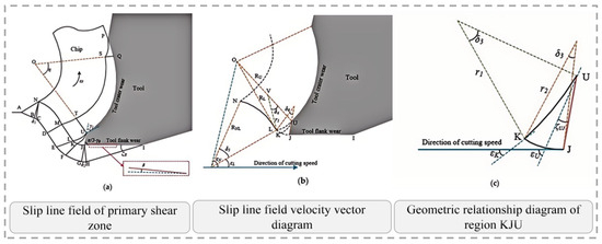
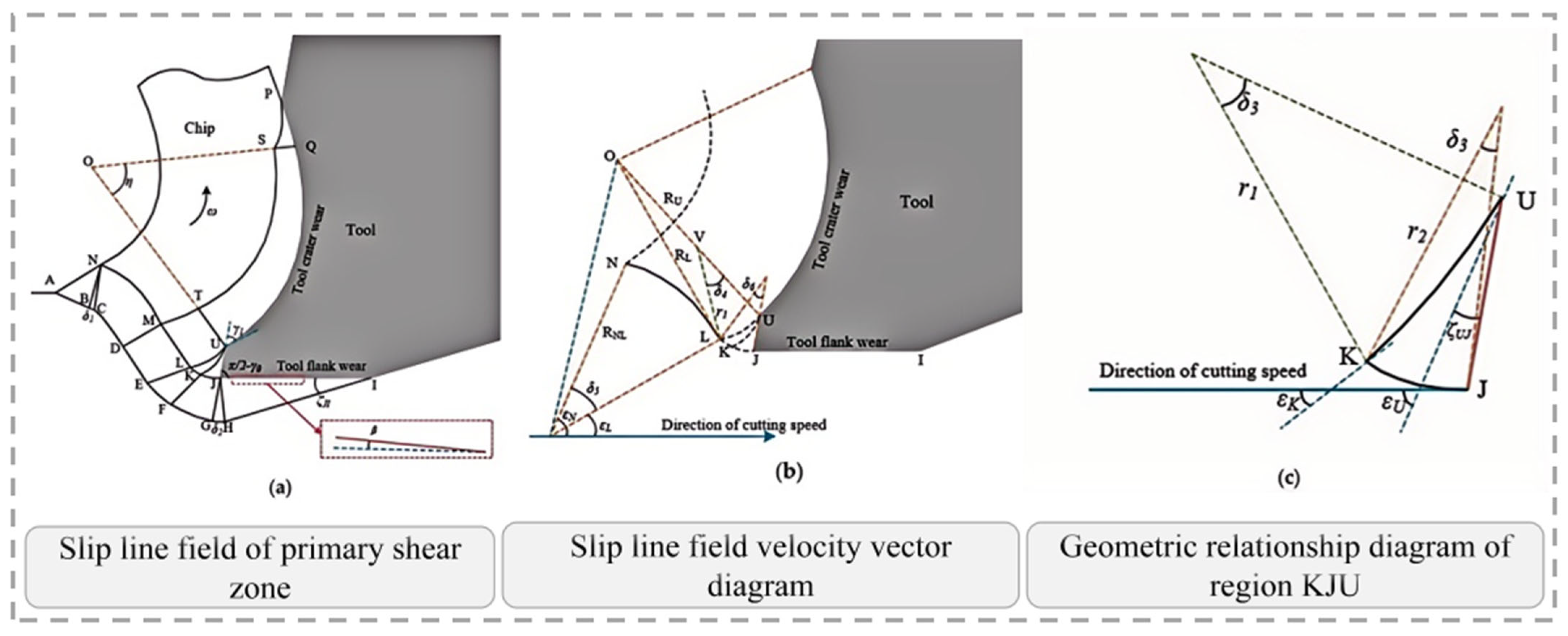
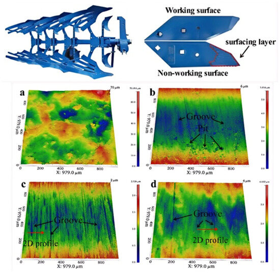
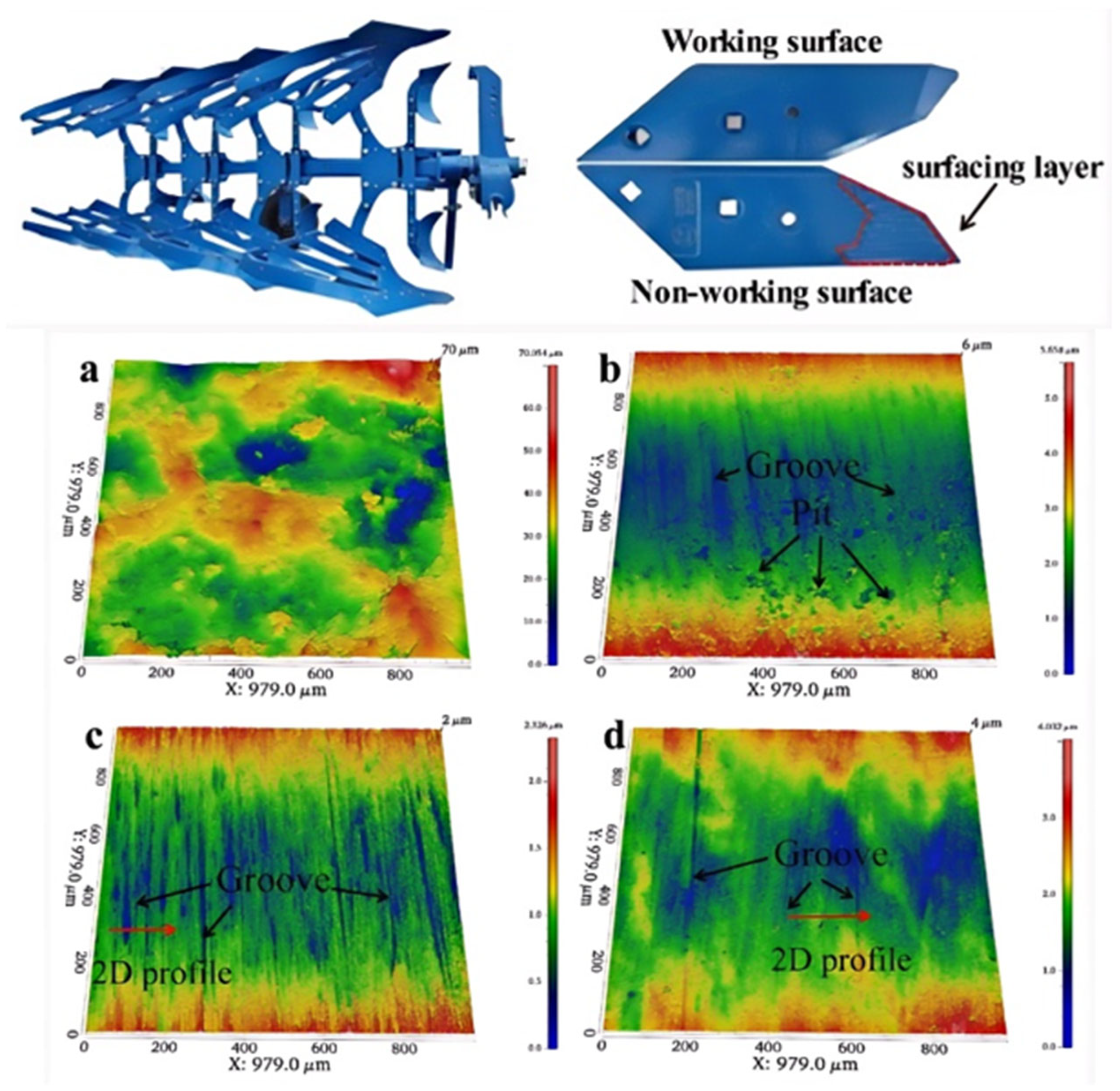
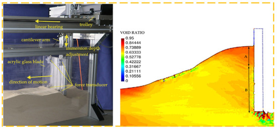
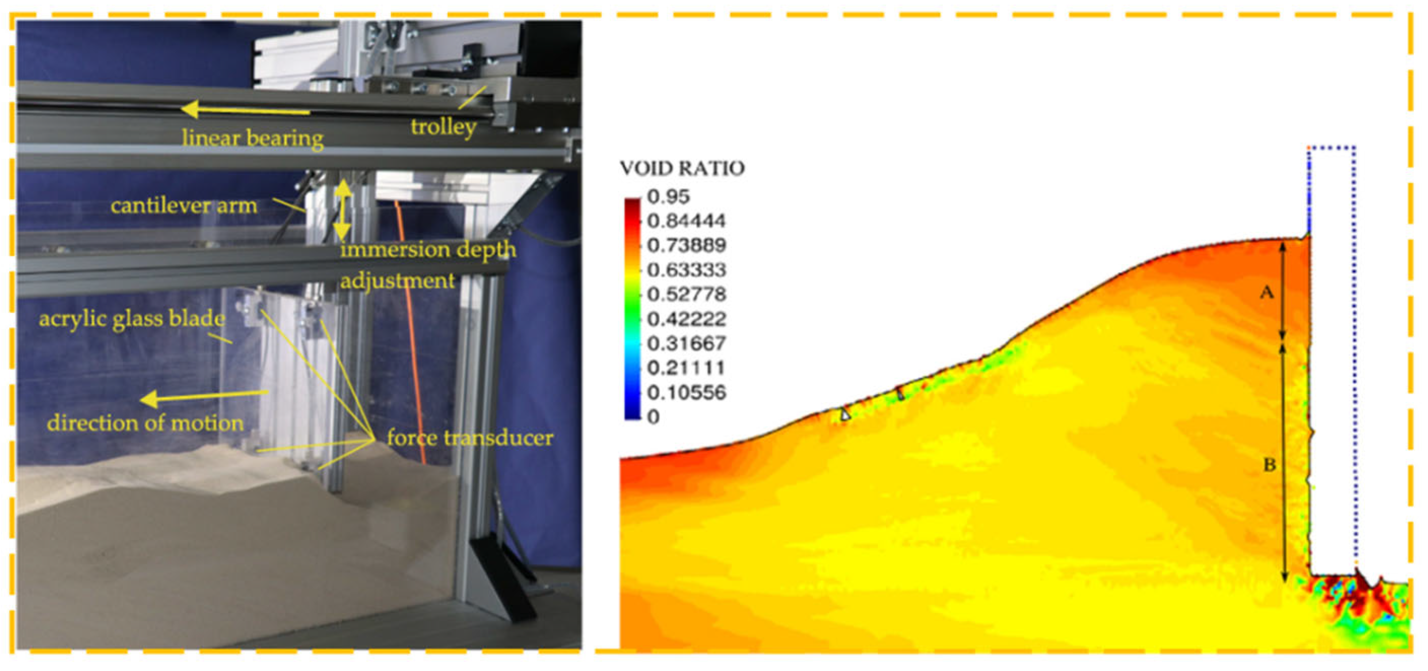
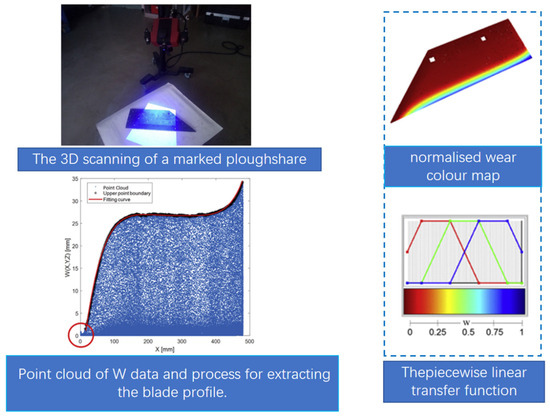
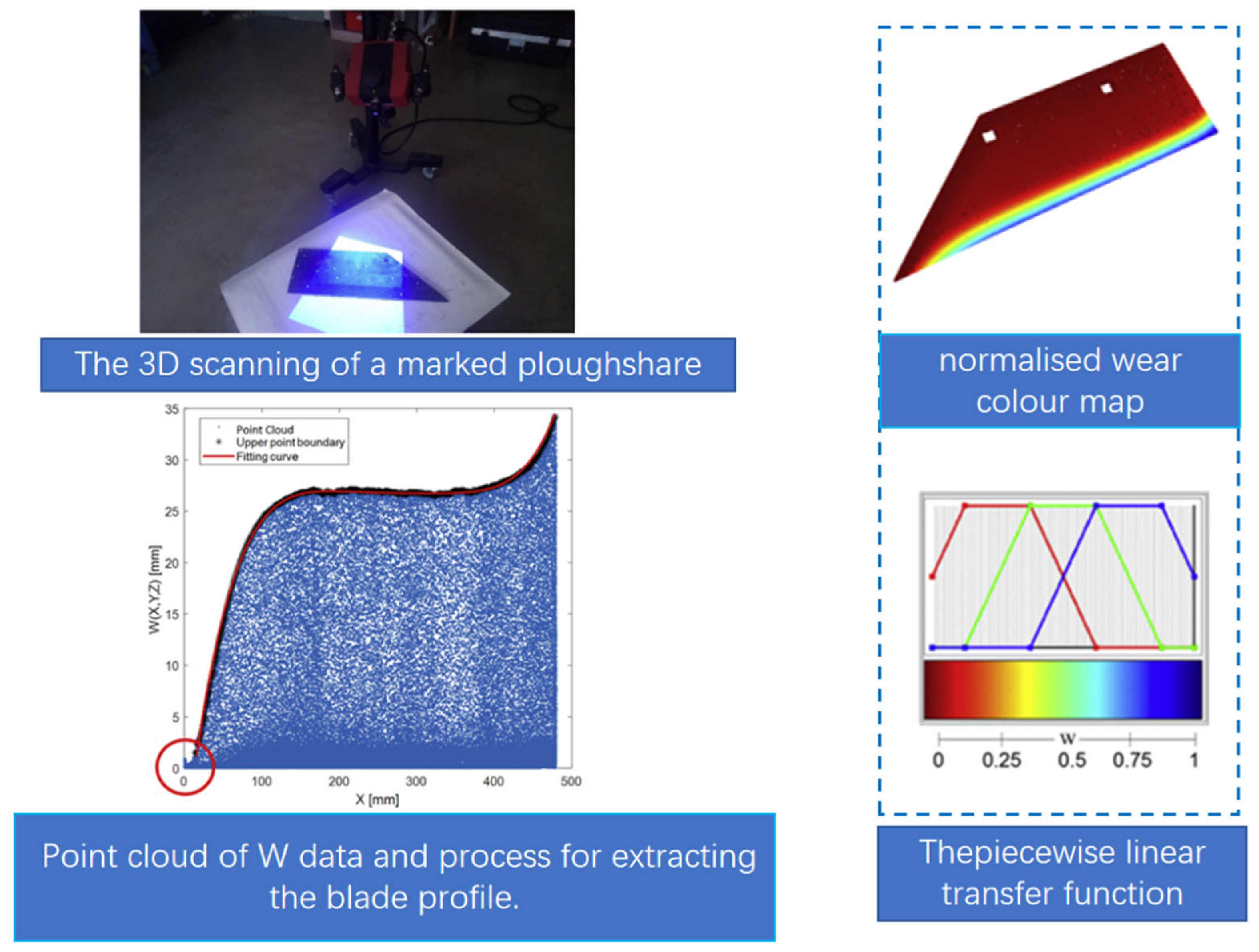
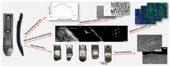
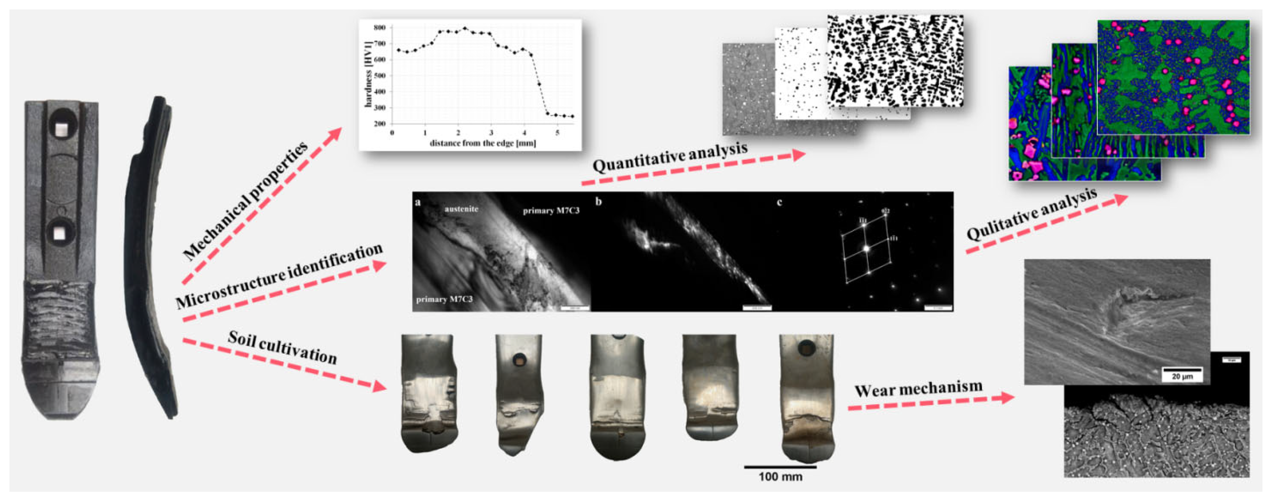
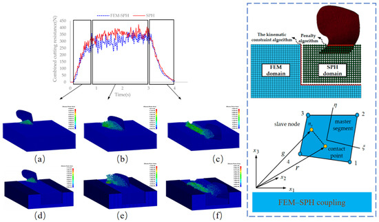
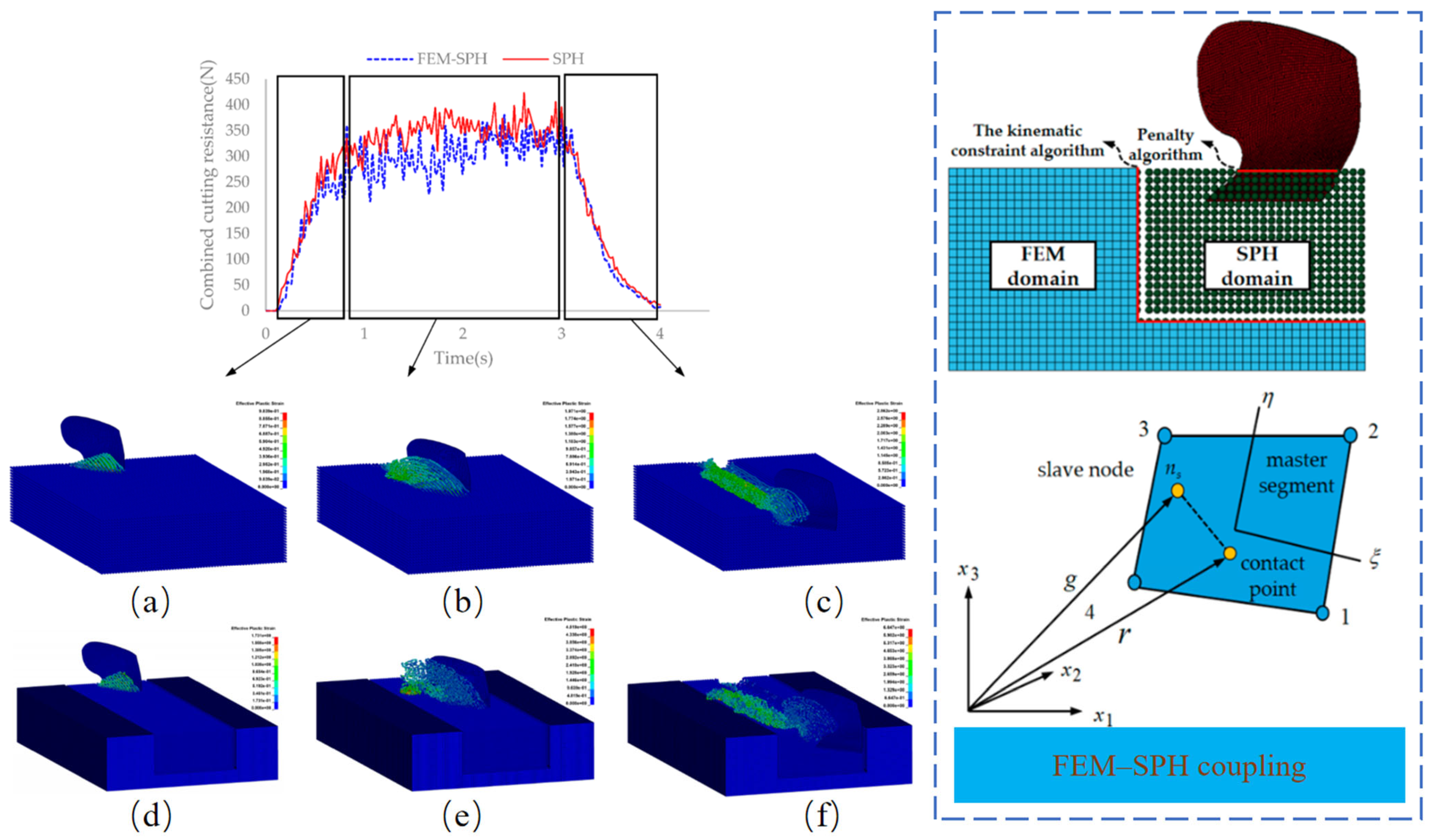
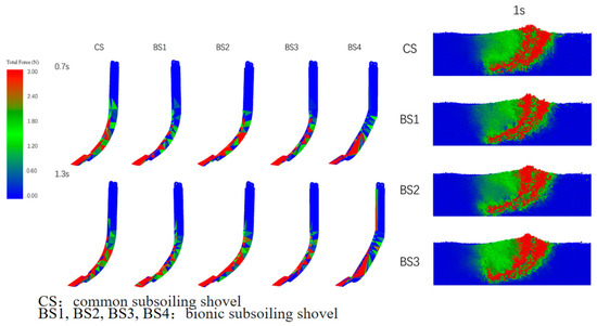
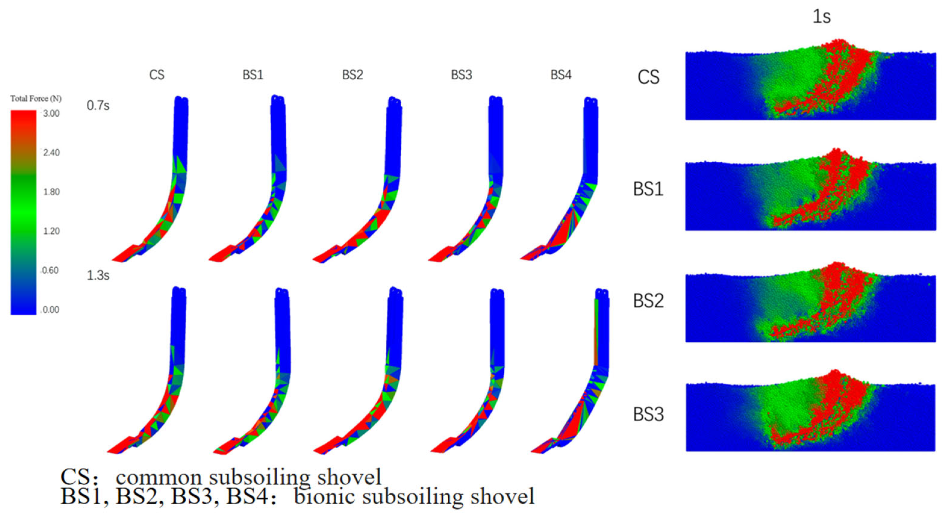
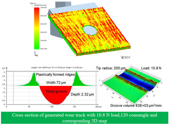
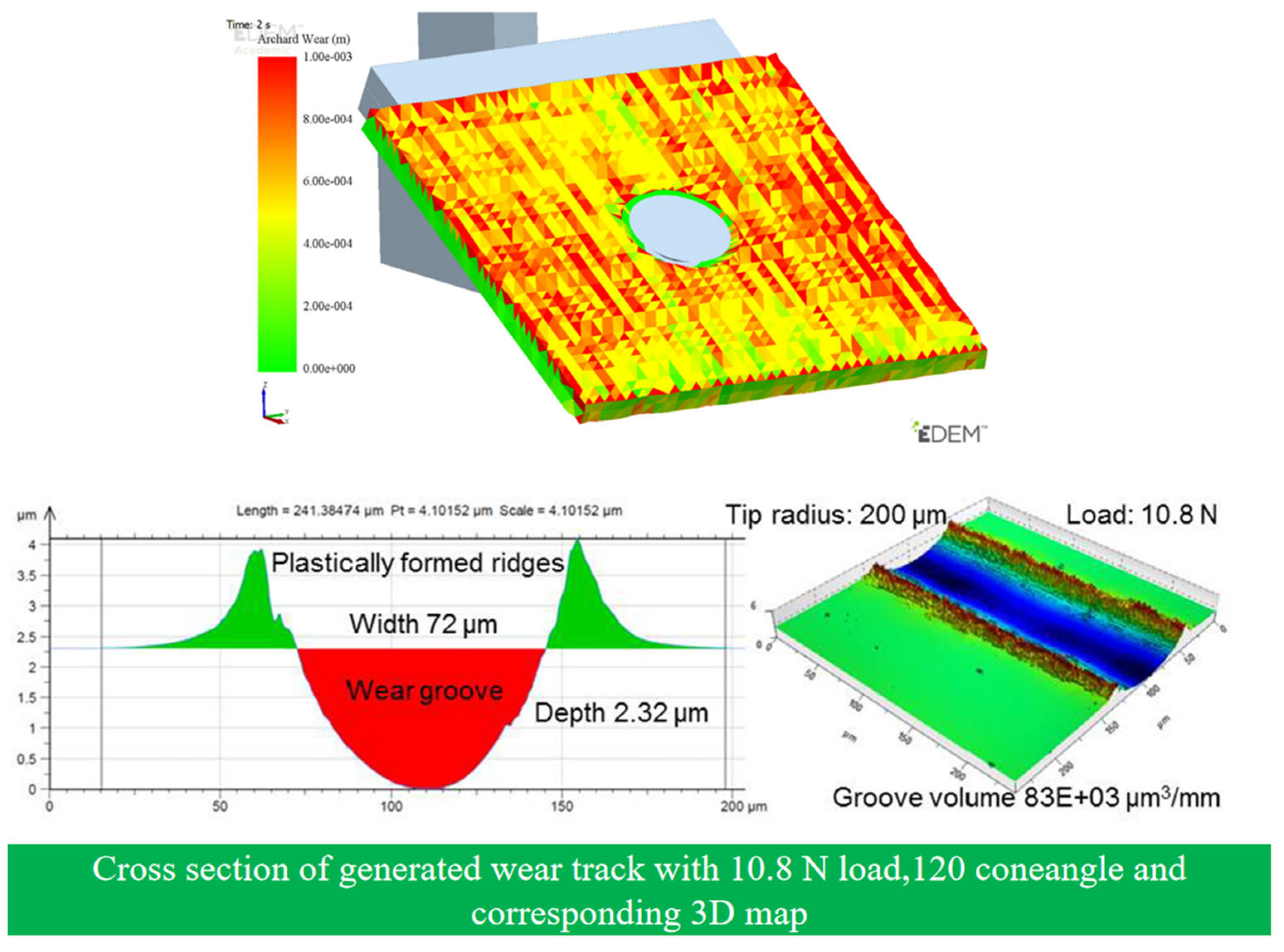
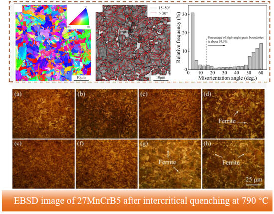
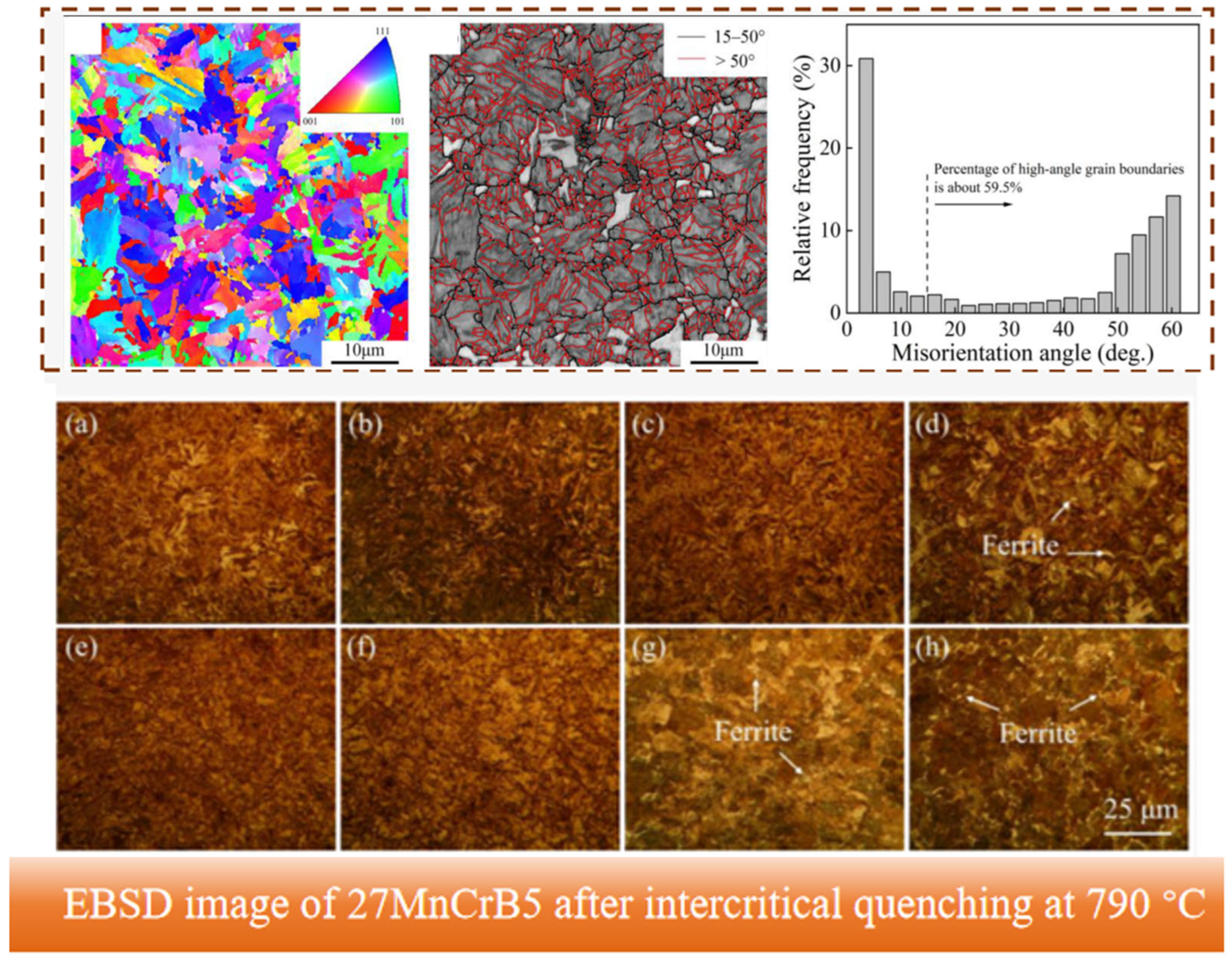
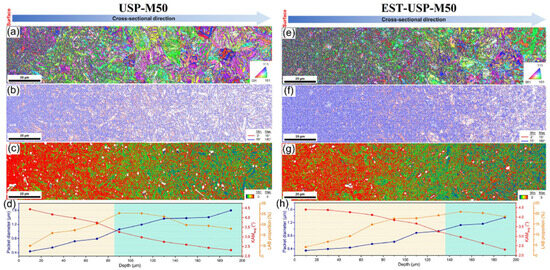
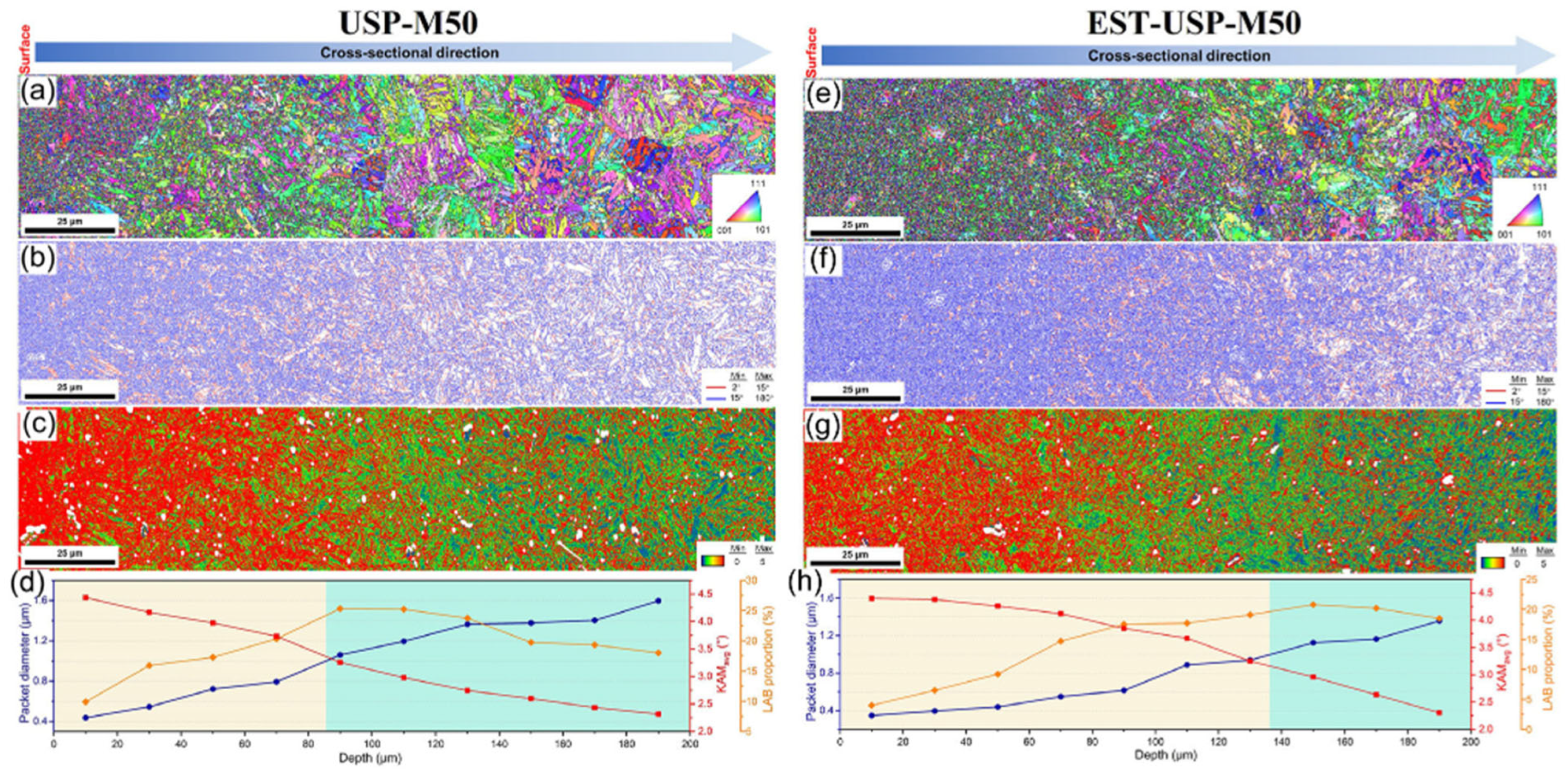
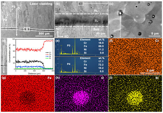
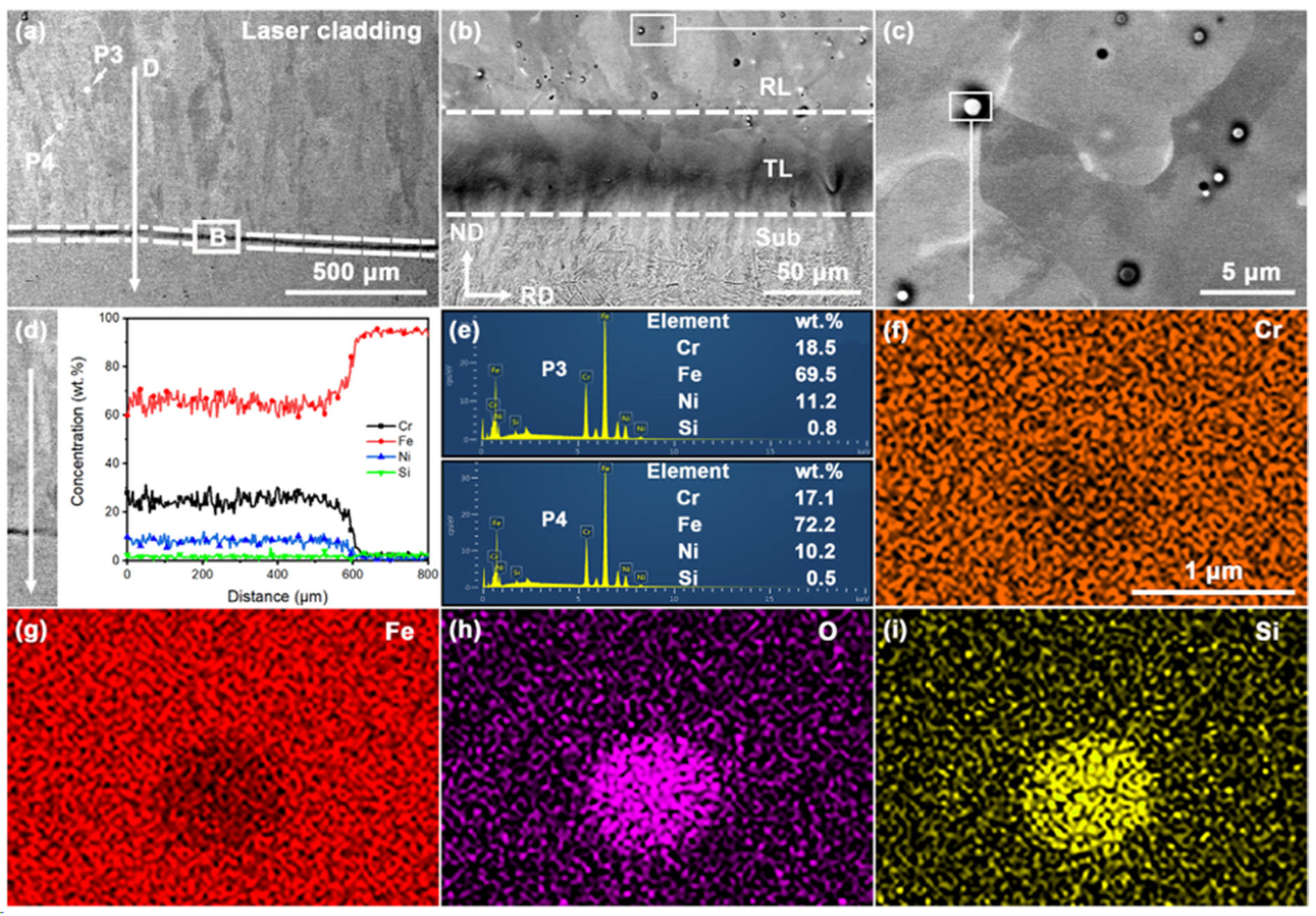
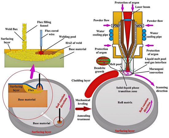
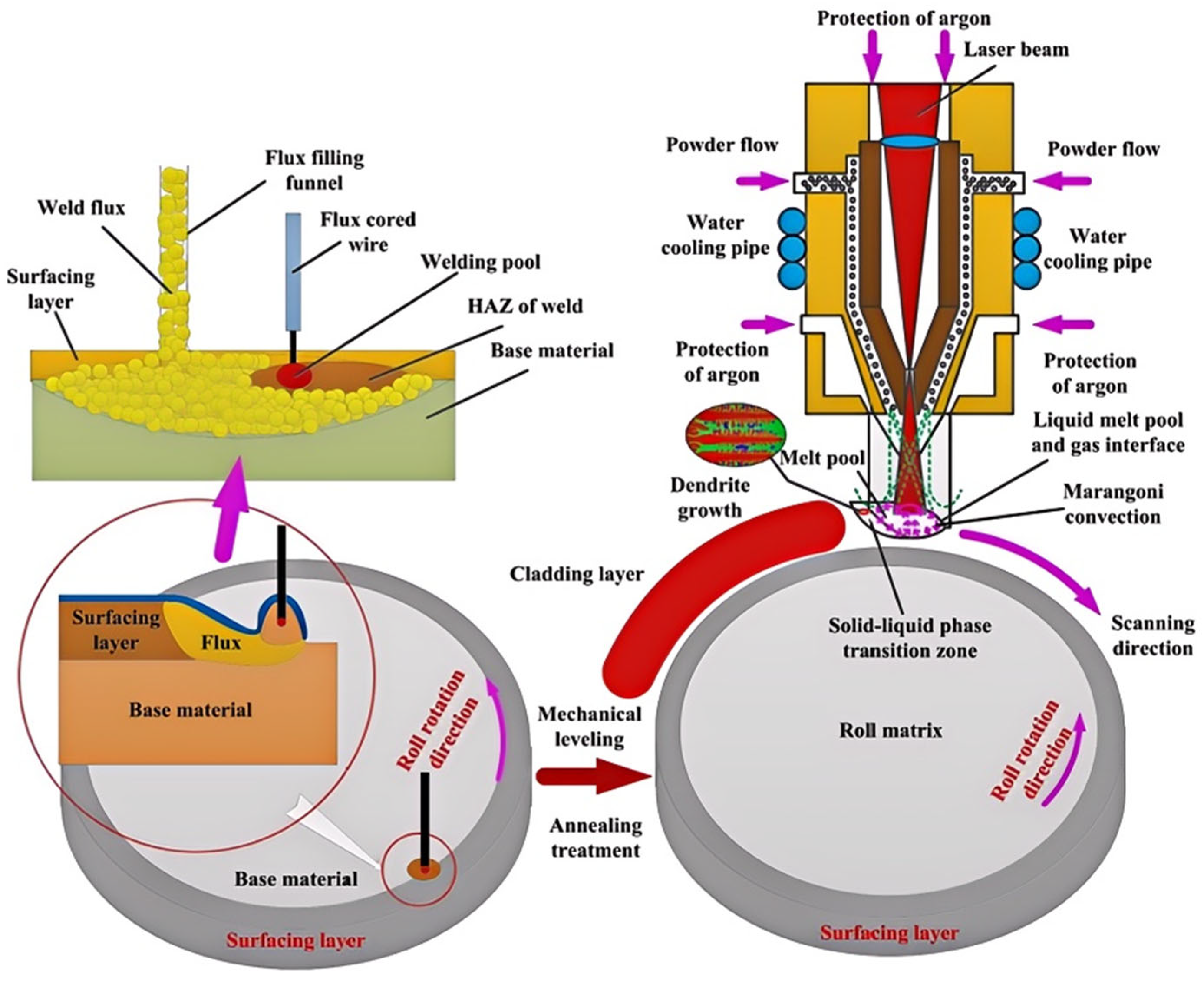
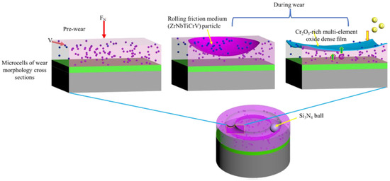
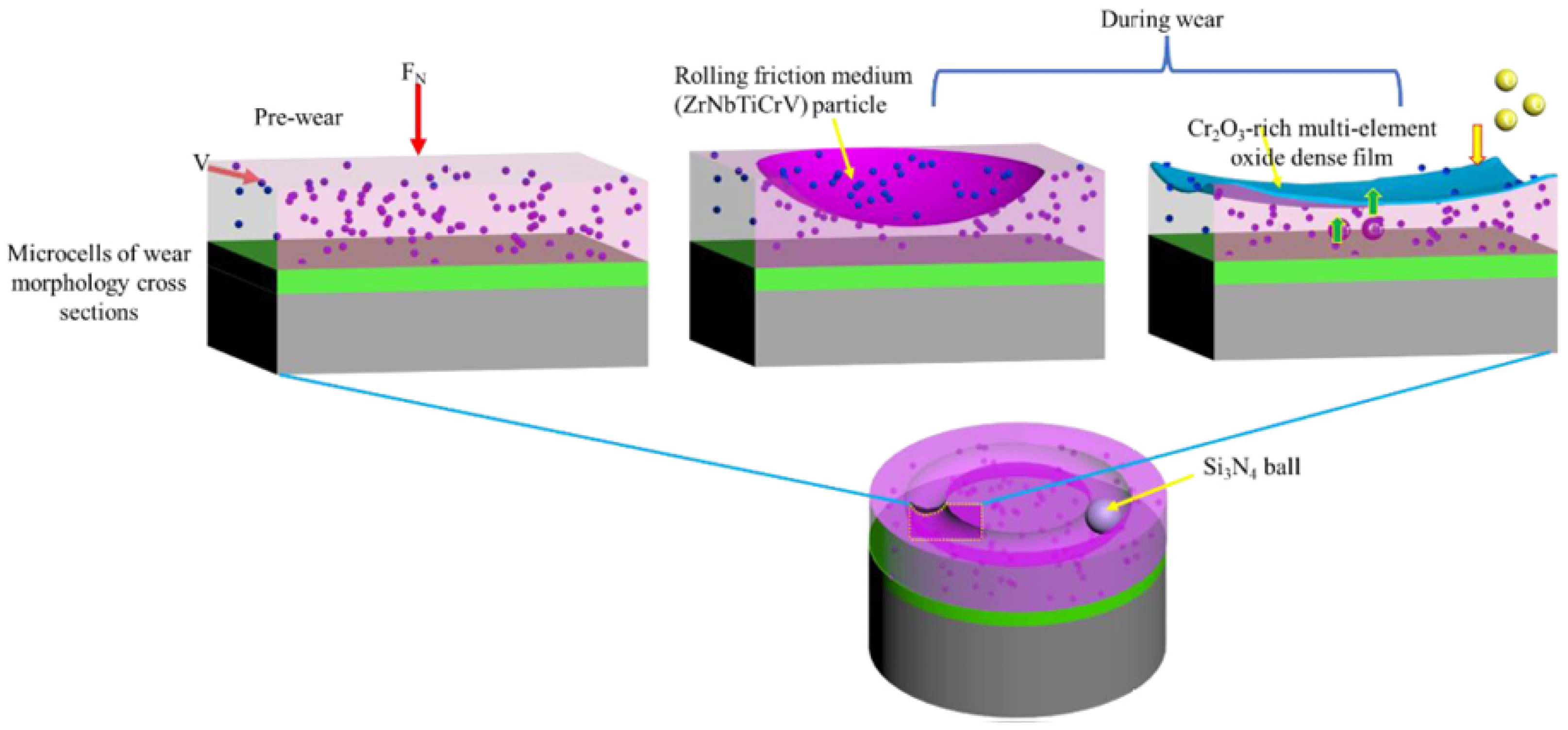
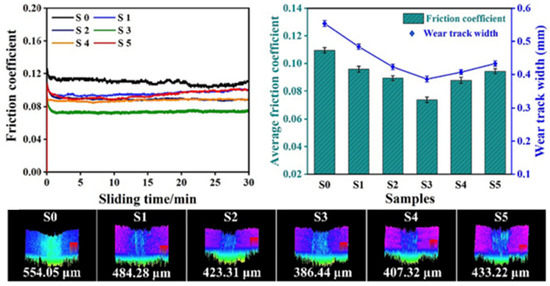
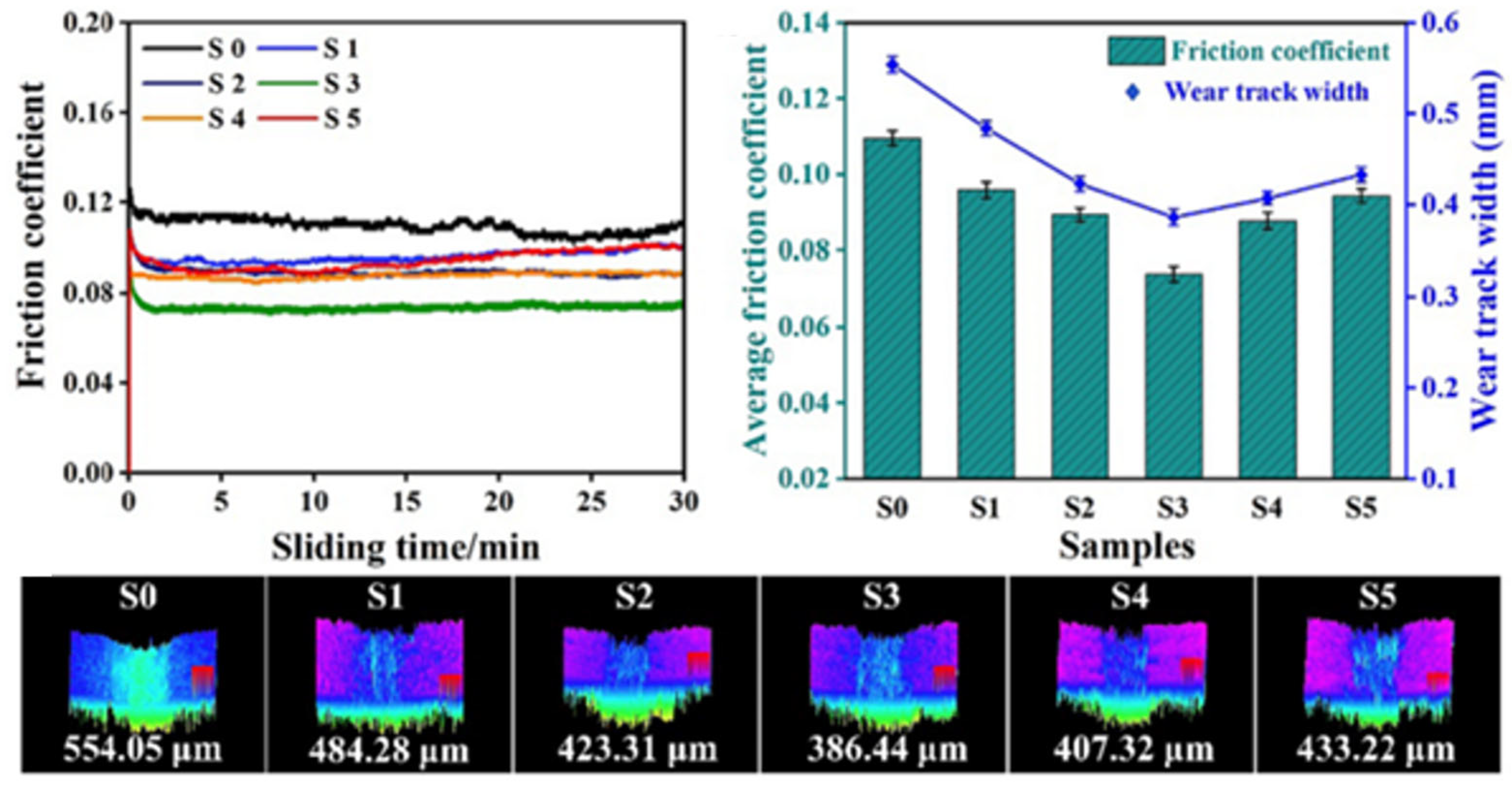
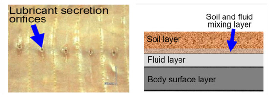
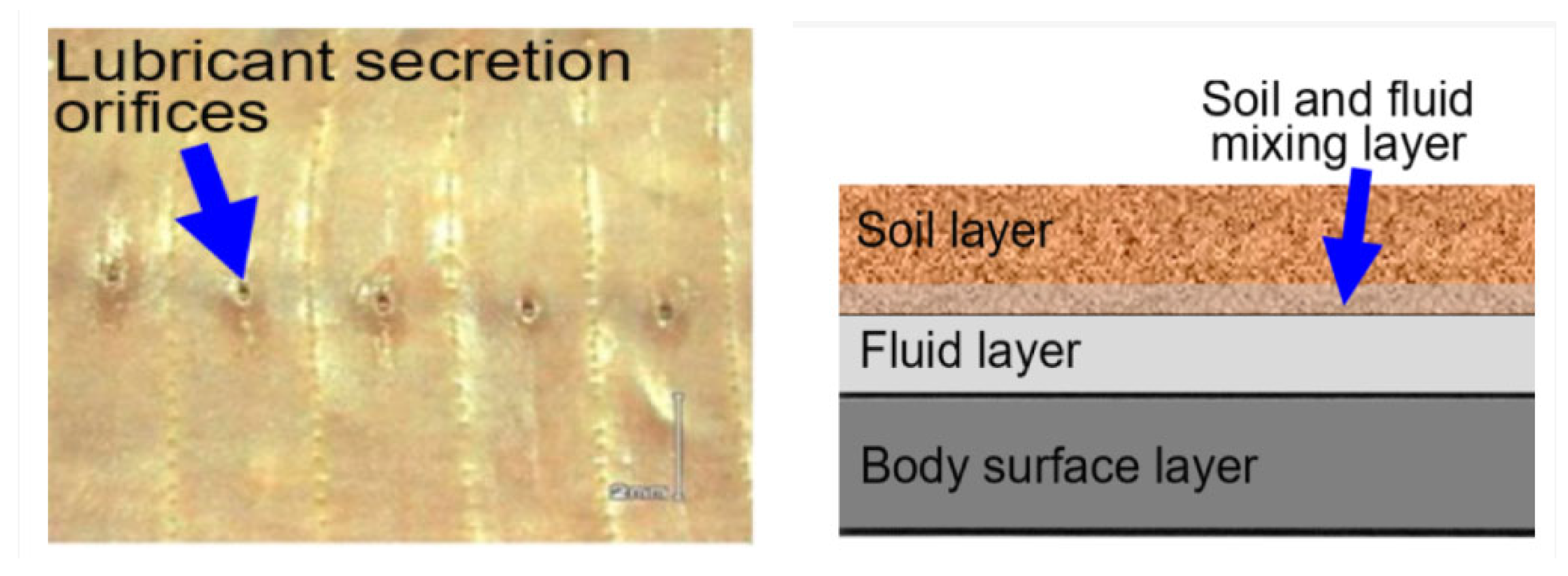
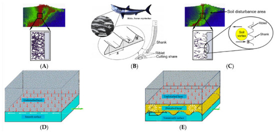
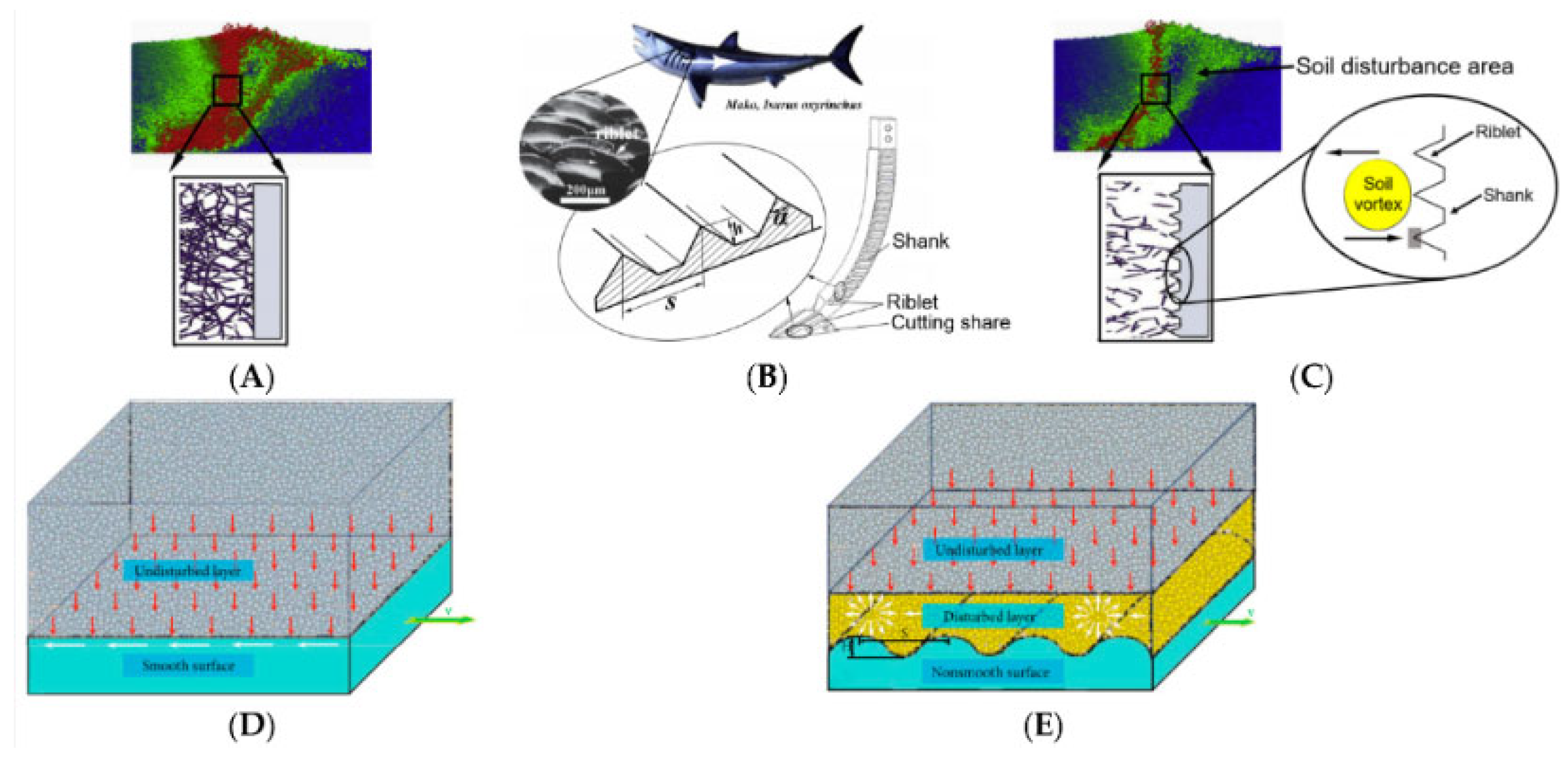

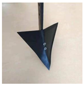
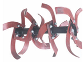
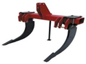
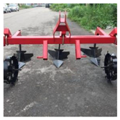
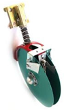
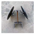
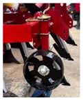
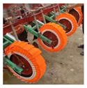
Disclaimer/Publisher’s Note: The statements, opinions and data contained in all publications are solely those of the individual author(s) and contributor(s) and not of MDPI and/or the editor(s). MDPI and/or the editor(s) disclaim responsibility for any injury to people or property resulting from any ideas, methods, instructions or products referred to in the content. |
© 2026 by the authors. Licensee MDPI, Basel, Switzerland. This article is an open access article distributed under the terms and conditions of the Creative Commons Attribution (CC BY) license.