


Abstract
Current design approaches for non-circular gears are generally restricted to predefined pitch curve geometries, lacking a unified methodology for systematically exploring wider families of admissible curves. To overcome this limitation, the paper proposes a generalized parametric design methodology capable of generating and evaluating an entire family of feasible pitch curves from a single analytical formulation—the Gielis’ superformula. Numerical analysis and CAD-based implementation are employed to identify a sub-family of generalized ellipses within the infinite family of Gielis curves that meet the geometric requirements for non-circular gear centrodes, namely closed and periodic profiles, smooth curvature, the absence of angular discontinuities and undercutting during tooth generation. The proposed methodology integrates the Gielis curves into gear design by (i) introducing gear-specific parameters, (ii) generating the conjugate pitch curve through the rolling without-slip equations, (iii) determining the center distance, (iv) determining the tooth number relation associated with the revolution ratio, (v) considering the curvature-based undercutting criterion and (vi) validating the resulting gears through CAD-based tooth generation simulations. This approach extends the geometric design space while providing a unified framework for the non-circular gears synthesis. Appropriate combinations of the Gielis parameters allow the amplitude, frequency and waveform of the transmission ratio function to be tailored to the kinematic requirements of variable-speed applications. Rather than identifying universal optimal values, the proposed methodology provides a framework for systematically evaluating Gielis parameter combinations against the geometric and gear-design requirements.
1. Introduction
Non-circular gears are used in mechanisms requiring a prescribed law of motion that cannot be obtained by conventional circular gears. Their transmission ratio varies continuously during meshing and is determined by the geometry of the conjugate pitch curves. Consequently, the synthesis of the pitch curves represents the fundamental step within the gear design procedure, since their geometry governs the transmission function, the pressure angle, the curvature distribution and the conditions of tooth generation. The theoretical foundations of non-circular gearing have been established in the classical works of Litvin [1,2] and subsequently extended through numerous analytical and numerical studies devoted to the synthesis of conjugate pitch curves, generation methods and practical applications.
Among the different families of non-circular gears, elliptical gears [3,4,5,6,7,8,9,10,11,12,13] have received the greatest attention due to their relatively simple geometry and smooth periodic transmission characteristics. Numerous modifications of the classical ellipse have subsequently been proposed to increase the flexibility of the transmission function; these include high-order ellipses, deformed ellipses, piecewise elliptical pitch curves and other generalized centrodes. The geometry of pitch curves derives from the hypotheses chosen to design the non-circular gears, whether based on the predefined driving gear pitch curve geometry or on the kinematic requirements, through the prescribed transmission ratio or the driven element’s motion law. Considering the driving pitch curve as the starting point of the non-circular gear design procedure, a hypothesis that is routinely used, its geometry was described by several mathematical formulations, including a classical or modified ellipse, a free curve described by Bézier/B-splines curves, a harmonic/N-lobed shape described by Fourier series, an epicycloid/hypocycloid, Limaçon/Pascal curve or the Bernoulli’s lemniscate [14,15,16,17,18,19]. The Gielis’ superformula [20] represented one of the most general parametric descriptions, since conventional ellipses, superellipses and a large variety of modified elliptical curves could be obtained by varying only a limited number of supershape parameters.
All these existing models provide effective solutions for particular non-circular gear families, but they do not fully resolve the problem addressed in the present study. Classical elliptical formulations offer compact analytical expressions but permit only limited and strongly coupled control of local curvature and transmission ratio shape. High-order and piecewise elliptical models increase geometric flexibility but require additional continuity conditions and segment-specific coefficients. Fourier and Spline representations can approximate highly complex curves, although their coefficients have limited direct geometric interpretation and do not automatically ensure pitch curve closure, convexity or undercut-free tooth generation. Previous applications of the Gielis superformula demonstrated its geometric flexibility, but a systematic mapping between its parameters, the closure of the conjugate pitch curve, the gear tooth parameters, the undercutting criterion, and the resulting transmission function has not been established.
The scientific problem addressed in this paper is therefore to identify and quantify the combinations of Gielis and gear-specific parameters that generate closed, smooth, manufacturable conjugate pitch curves with predictable transmission ratio characteristics. The novelty of the present study consists of establishing a direct parametric link between the Gielis superformula, the closure and scaling equations of conjugate non-circular pitch curves, the gear tooth number and module parameters, the undercutting criterion and the resulting transmission ratio indicators. Through a unified framework, the presented generalized parametric methodology, based on the Gielis superformula, allows admissible pitch curves to be generated, evaluated and transferred into non-circular gear design.
The research was based on numerical analysis, parametric investigation, graphical visualization and CAD simulations. Numerical computations and graphical representations were performed in Microsoft Excel, while geometric modeling and gear tooth generation simulations were carried out in AutoCAD 2025, using original AutoLISP codes developed by the authors.
The proposed methodology is intended for the preliminary design stage of non-circular gear trains with prescribed variable transmission ratios. Potential applications include packaging and printing machinery, textile and food-processing equipment, indexing mechanisms, variable-displacement pumps, positive-displacement flowmeters, robotic devices and other motion-control systems in which non-uniform output motion is required. The present study establishes the geometric and kinematic basis for such applications, while application-specific analyses involving load capacity, contact stress, efficiency and dynamic behavior remain subjects for future investigations.
1.1. Overview of Analytical Models for the Elliptical Pitch Curves Representation
Limiting the non-circular driving gear’s pitch curve to the enlarged elliptical shape family, its geometry was described through a variety of analytical formulations in order to align it with the focus of the studies. Emura and Arakawa [21] designed non-circular gears to be used within a steering mechanism able to turn, within a small radius, a wheeled robot, such as the carrier robots used in industrial production lines. It was proven that the non-circular gears are elliptical gears, whose pitch curves are described, in polar coordinates, as:
where ν0, νj are the number of lobes of elliptical pitch curves; ε0, εj—the eccentricity of elliptical pitch curves; l0, lj—parameters which determine the size of elliptical pitch curves.
Chang and Tsay [22] developed a computer program wherein the generation of a non-circular gear pairs, using an involute-shaped shaper cutter, is simulated. The driving gear pitch curve, as an elliptical curve, is described relative to the coordinate system whose origin is attached to one of the ellipse foci, as
where parameter is the eccentricity of the ellipse; a1—the major semi-axis length; and b1—the minor semi-axis length.
Bair developed computer aided designs of involute and circular-arc elliptical gears trains, simulating their manufacture by different cutters [8,23,24,25]. Both driving and driven gears are produced as identical elliptical gears, whose rotation axes coincide with their geometrical centers. The algorithms generation consider the following polar equation of the driving gear elliptical pitch curve:
where parameter is the eccentricity of the ellipse; a1—the major semi-axis; b1—the minor semi-axis.
Figliolini and Angels [26] developed a general algorithm as a powerful instrument for the elliptical gears design, with any number of lobes and concave–convex pitch curves, respectively, based on the envelope theory and the consideration of a conforming shaper cutter with involute tooth profile. The pinion and gear pitch curves are expressed through the polar coordinates:
by means of the current position vector:
where i = 1 is specific to the pinion; i = 2 is assigned to the gear; rA, rB are the maximum and minimum pitch radii; ni—the number of the pinion/gear lobes; c—the gears center distance, further expressed as a function of the rA, rB, ni parameters; θi—the rotational angle for the pinion and gear, also related through the rA, rB, ni. The pinion coordinates are calculated using the upper sign of the denominator, while the lower sign is specific to gear.
Litvin et al. [1,2] developed a series of investigations on conventional and modified elliptical gears considering the polar description of the driving pitch curve as:
or
where p = a(1 − e2), e—the ellipse eccentricity; ∈ [0, 2πn], n—the driving gear revolutions for one revolution of the driven gear, during a period; and mI, mII—real coefficients that are considered for the two halves of the ellipse. In order to be in tangency, in their common point, the two branches of the modified ellipse should satisfy the relationship: . The sign (+) or (−) depends on which of the two ellipse foci is selected as the gear center of rotation. In case of different numbers for the conjugate gears rotations and different coefficients dividing the polar angle, elliptical shape for the driving pitch curve leads to modified elliptical driven pitch curve, lobated and oval shapes being particular cases.
Tsay and Fong [27] applied the Fourier series to approximate the non-circular gears pitch curves, in order to improve the flexibility of their design. When the driving centrode’s geometry is the initial data within the design algorithm, represented by:
the usage of Fourier series
assumed the coefficients of the Fourier series, a0, a1, … an, b1, …, bn to be determined. Based on the approximated pitch curve, a further mathematical model of the non-circular gears tooth profile is derived using a standard rack cutter for the gears cutting process.
Luo et al. also used Equation (5) to generate elliptical gear drives whose pressure angle variation was further analyzed [28].
Li and Zhu [29] introduced high-order elliptical pitch curves, with modified geometry for the non-circular gears with infinitely variable transmission, aiming to eliminate cusps between every two neighboring lobes of pitch curves, to improve curve smoothness and to enhance gear manufacturability, respectively. The high-order elliptical pitch curve is expressed by the polar equations:
where j = 1, 2, ….. , —the number of lobes of the pitch curve of driving non-circular gear; —the order of the elliptical pitch curve; —the eccentricity of the elliptical pitch curve; —the modified coefficient of the j-th elliptical pitch curve; and —the pitch of the non-circular gear pair that cand be represented as:
where m is the modulus of the driving and driven non-circular gears; —the number of teeth of driving non-circular gear. For the high-order elliptical pitch curve of driving non-circular gear, each modified coefficient should satisfy and .
Liu et al. [30] developed a general mathematical model that describes a piecewise deformed elliptical gear, with a highly changeable geometry for its closed aperiodic pitch curve. Starting from the polar equation of the high-order ellipse:
the piecewise deformed ellipse, as an N-segment deformed ellipse, is expressed in extended form as:
where p = , A is the major semi-axis; e—the eccentricity; n—the ellipse’s order; N—the segments number of the gear; j = 2, 3, … N; m1, mk—the modified coefficients; ; must satisfy and . Adjusting the parameters A, e, N and mk, the pitch curve geometry is adjusted, i.e., the gear ratio is easily modified to meet a variety of transmission requirements.
Although all previously mentioned analytical models have demonstrated their effectiveness for the particular pitch curve geometries for which they were developed, each formulation remains dedicated to a specific class of non-circular curves. Consequently, the existing approaches do not provide a unified parametric framework capable of systematically generating and investigating a broad spectrum of pitch curve geometries within a single analytical formulation. This limitation motivates Andrei and Vasie [31,32] to adopt the Gielis superformula [16] whose parametric flexibility enables the description of an extensive family of pitch curves, using a common mathematical representation. This superformula is further used within the present study, in order to define close driving non-circular centrodes whose geometries could be controlled by a small set of parameters, with consequences on the resulting transmission ratio characteristics of conjugated pitch curves. Since m is conventionally used to denote the gear module, the corresponding parameter in the original Gielis superformula is denoted here by n, to avoid ambiguity:
where is the polar angle, considered to vary within a complete rotation; a, b—the conventional ellipse semi-axes lengths, inscribed or circumscribed about the centrode; n—a real positive parameter that introduces the curve’s rotational symmetry; n2, n3—real positive parameters that lead to inscribed (n2 = n3 < 2) or circumscribed (n2 = n3 > 2) “polygonal” shapes, related to the conventional ellipse; n1—a real positive non-zero parameter that modifies the curve’s geometry with respect to the linearity/convexity of the sides and the sharpness/flattening of the corners. The polar radius refers to the normalized supershape, with the conventional ellipse semi-axes lengths close to unit.
1.2. Research Motivation, Objective and Contribution
Although numerous analytical representations of non-circular pitch curves have been proposed, they are generally limited to particular curve families or specific applications [33,34,35,36]. A generalized methodology for assessing whether an arbitrary parametric curve satisfies the geometric requirements necessary to serve as the pitch curve of a non-circular gear has not yet been established.
Accordingly, the present work introduces Gielis supershapes as potential pitch curves whose geometry is highly flexible and governed by six independent parameters. Furthermore, by incorporating additional parameters associated with gear tooth geometry and gear-pair kinematics, the scope of the investigation is extended considerably beyond the purely geometric framework.
Within this context, the following objectives are proposed as part of the filtering algorithm applied to the variation of the geometric and kinematic parameters of a gear pair in which the driving gear pitch curve is represented by a Gielis curve: (i) ensuring the closure and periodicity of the conjugate centrodes/pitch curves, with aperiodic pitch curves being excluded from the present study; (ii) avoiding angular points and maintaining curvature values within limits compatible with practical tooth generation and manufacturing constraints; and (iii) identifying optimal gear-specific parameters capable of preventing the occurrence of tooth undercutting.
As a final objective, the analysis of the influence of the governing parameters on both the geometry of the gear pair and the transmission ratio enables the rapid selection of suitable parameter combinations and the correct generation of a non-circular gear pair whose motion follows a prescribed function, with amplitude and frequency characteristics tailored to the intended application.
Since the family of Gielis curves is theoretically infinite and the number of governing parameters is relatively large, the present study is restricted to the particular case of almost convex superellipses with a predefined ratio between their principal axes. The mathematical correspondence between the conventional ellipse and its Gielis-based formulation is derived in Section 2 and constitutes the foundation of the subsequent parametric analysis.
The numerical analyses and graphical representations are based on the integration of Microsoft Excel and AutoCAD software, wherein original computational routines were specifically developed.
Despite being demonstrated for the particular case of convex superelliptic pitch curves, the proposed approach provides a general and systematic framework for the design of non-circular gear pairs derived from an initial geometric assumption, namely the prescribed geometry of the driving gear pitch curve.
2. Materials and Methods
2.1. Parametric Definition of Generalized Elliptical Gielis’ Superformula-Based Pitch Curves
Since the conventional and modified elliptical gears are the most popular non-circular gears subjected to investigations, the ongoing study is focused on the class of “elliptical” curves that could derive from the Gielis’ supershapes family.
Considering the driving non-circular centrode as a conventional ellipse whose center coincides with the center of rotation, with the major and minor axes aligned with the X and Y axes of the attached cartesian coordinate system, its equation:
when converted to polar form, by substituting and , becomes
When compared with Equation (12), the above equation describes the standard ellipse as a subset of the Gielis’ supershape, defined by the following parameters: n1 = n2 = n3 = 2. To recover the standard elliptical form, the trigonometric arguments must satisfy , resulting in n = 4. For the particular case of the Gielis superellipse corresponding to the classical ellipse, the rotational symmetry parameter takes the value n = 4. Consequently, the resulting radial function exhibits four extrema over one revolution, namely two maxima along the major axis and two minima along the minor axis. It should be emphasized that the parameter n is a parameter of the analytical representation and should not be interpreted directly as the order of the geometric symmetry group of the resulting curve. For the particular case n = 4 and , the superformula reduces exactly to the classical ellipse. By incorporating the Gielis’ elliptical supershapes into non-circular gear theory and exploiting the flexibility provided by the remaining superformula parameters, this study prioritizes the analysis of the interplay between pitch curve geometry and transmission ratio characteristics.
Consequently, the present study is based on the following hypotheses/initial data for the design of non-circular conjugate centrodes:
(i) The driving centrode’s geometry is assumed to be a normalized superellipse (with semi-axes lengths close to 1) that is analytically described, in terms of the Gielis’ superformula, by:
Going on with the conjugate centrode’s procedure, once the driving centrode is defined, the normalized driven centrode is analytically expressed by:
where is the centrodes constant center distance; —the polar angle of the driven centrode:
The center distance A* is specific to every non-circular mating normalized centrode pair, determined by the variation of the driven centrode rotation angle. The calculation of the center distance is based on the second assumption, respectively:
(ii) In one motion period, the conjugate centrodes perform N1 and N2 rotations, respectively. An iterative procedure enables the center distance calculation, from the equation:
2.2. Adaptation of the Generalized Ellipses to Non-Circular Gear Theory
In order for the non-circular centrodes, defined by Equations (13)–(17), to be regarded as potential pitch curves of a gear pair, new defining parameters are involved, specific to gears theory, i.e., the modulus m and the gears number of teeth, z1, z2. That being the case, the driving normalized centrode defined by Equation (13) is further scaled, to obtain the required pitch curve length that would enable the teeth correct arrangement. In case of prescribed modulus and number of teeth, the driving pitch curve radius will be accordingly defined by
where is the scale factor:
is the length of the normalized driving centrode,
The center distance as well as the geometry of the driven pitch curve are updated/scaled, deriving from the corresponding Equations (15)–(17).
The instantaneous gear ratio can be expressed by using the current radii of either the conjugate pitch curves or the normalized conjugate centrodes; its equation constitutes the analytical bridge between the geometric description of the pitch curves and the kinematic analysis developed in the remainder of the paper:
where , are the angular velocities of the driving and driven gears, respectively; , —the instantaneous pitch radii of the driving and driven pitch curves.
In summary, the geometry and kinematics of a pair of conjugate non-circular pitch curves, with the driving one defined by four extreme radius values (n = 4, as in an ellipse) through Gielis’ superformula, is controlled by several real parameters: a, b (the semi-axes lengths), n1, n2, n3 (the Gielis’ superformula exponents), N1, N2 (the mating pitch curves number of rotations during a period), m, z1, z2 (the gear-specific defining parameters). The influence the parameters have on the pitch curves geometries and gear ratio variation, respectively, is an important issue to be considered since it is directly linked to the transmission’s kinematic behavior, rolling contact smoothness and motion stability under operating loads.
2.3. Geometric Analysis of the Conjugate Non-Circular Pitch Curves
From a geometric standpoint, the following aspects are essential when dealing with conjugate non-circular pitch curves: the curves closure and periodicity, the local curvature fields and the preponderance of convexity.
2.3.1. Conjugate Pitch Curve’s Closure and Periodicity
To simplify the analysis of the pitch curves’ closure, the normalized centrodes will be considered, since the scaling procedure does not affect this characteristic. It is obvious that, whatever the a, b, n1, n2, n3 parameters are chosen, the driving centrode (Equation (14)) is closed, since
To find out the necessary condition for obtaining a closed driven centrode, repeated numerical generation of the conjugate centrodes is proposed, with various parameters chosen to define Equations (15)–(17), corresponding to the considered cases. The numerical analysis performed in Excel, together with graphical simulations implemented in AutoCAD, using original AutoLISP routines, revealed that the key factor ensuring the closure of the driven pitch curve, and consequently the periodicity of motion, is the existence of a specific rational relationship between the numbers of revolutions of the two conjugate centrodes. Choosing intermediate ratios produces a non-closed driven curve, with an incomplete lobe, a configuration that could be suitable for oscillatory motions.
For the Gielis function defined by Equation (14), with , the mathematical period depends on the selected parameter values, as follows:
- -
- If a = b, n2 = n3, the mathematical period is T = π/2, since
The corresponding normalized centrode has four lobes of identical size and curvature, a perfect 4-fold rotational symmetry being visualized. As the conjugate curve, the driven centrode will also repeat the geometry within every π/2 angle (Figure 1a);
Figure 1.
Periodicity of Gielis’ function/visualization of lobes for normalized conjugate non-circular centrodes, when the rotational symmetry parameter n = 4. (a) a = b = 1, n1 = 2; (b) a = 2, b = 1, n1 = 2, n2 = 2. The circles drawn in black indicate the centrodes’ centers of rotation.
- -
- If a ≠ b, n2 ≠ n3, the mathematical period is reduced from T = 2π (the standard value in case of basic sine and cosine functions) to the period T = π, due to absolute values of its terms:
In visual terms, this periodicity should be identified on the curve’s graphic representation, through the number of lobes. Due to the variation of the other exponent parameters, often the lobes’ appearance is changed and potential merging may occur (Figure 1b), creating confusion between the function’s mathematical period and the graphical representation.
2.3.2. Variation of Curvature
An initial functional requirement within the non-circular gear design is the analysis of the pitch curve geometry, focused on the curve’s convexity and curvature. The traditional gear manufacturing process, based on the classical rolling or involute-based conjugation requires a pitch curve that is strictly convex [1,2]. However, modern approaches enable concave–convex non-circular gears to be designed and manufactured using numerical conjugate flank synthesis and the face-milling method [37,38].
The pitch curve’s radius of curvature is the main geometric criterion necessary for distinguishing between convex and concave segments through the curvature sign; moreover, ensuring that the minimum pitch curve’s radius of curvature exceeds a safety threshold that mainly depends on the tool geometry ensures the manufacturing feasibility, proper tooth geometry and appropriate operating conditions.
As shown in the literature [2], to enable the non-circular gear manufacture and to avoid undercutting, the radius of curvature of a gear’s pitch curve, ρ, when the manufacture involves classical rolling generation, should be greater than the “threshold”:
where m is the gears modulus; —the coefficient of the tooth addendum (for a standard gear tooth, = 1); and αc—the pressure angle. It should be noted that the present criterion addresses only the prevention of undercutting. Other manufacturing requirements, such as the minimum tooth tip thickness, depend on the detailed tooth geometry and are therefore outside the scope of the present geometric investigation.
Using the pitch curve curvature k as the reciprocal of the radius of curvature and the definition of the instantaneous curvature for a planar curve that is expressed by polar coordinates, the above inequality becomes:
where r′ and r″ are the first and second derivative of the function r, respectively.
The curvature analysis is developed on both conjugate non-circular pitch curves, with the driving element chosen from the elliptical family of the Gielis’ supershape and scaled to correspond to a prescribed modulus and number of teeth (Equation (18)). The following issues are of interest: (i) the influence the defining parameters have on the sign of the pitch curves curvature, related to the curves convexity, and (ii) the allowed parameters variations that would fulfill the prescribed condition (Equation (26)).
To provide a controlled framework for assessing the individual effect of each variable on the shape and curvature characteristics of the generated conjugate non-circular gears pitch curves, the study is conducted considering the following hypotheses:
H1.
To be focused on the modified elliptical family of the Gielis’ supershapes, from which the driving centrode is chosen, with no sharp corners, the exponent parameters are considered in the vicinity of value 2, specific to standard ellipse. Also, to reduce the number of parameters involved in the analysis, the semi-axis length b is considered equal to 1.
H2.
Each parameter’s influence is analyzed by systematically isolating and varying it, while the other parameters are kept at constant values.
H3.
The choice of the gears-specific parameters, i.e., modulus and statement content the number of teeth of gears, considers their potential values derived from an initial analysis of the tooth undercutting. To fulfill Equation (26), where is considered at the standard value and the pitch curve minim radius of curvature is expressed by the radius of curvature of its generating normalized centrode, it is necessary that [1]:
In terms of centrode’s curvature, the above relation can be written as
and
respectively.
Equation (29) highlights the significance of the choice of the number of teeth of the gears. Related to the pair of conjugate pitch curves, the driving component’s number of teeth may be chosen as
As regards the driven gear’s number of teeth, two requirements must be satisfied, one considering a similar inequality that involves the specific pitch curve maximum curvature and the second one that relates the rotations of the two gears. Therefore, the driven gear’s number of teeth should be chosen as
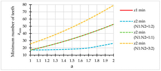
As an illustrative example, Figure 2 can be used as a design tool for the selection of the minimum admissible number of teeth, for both the driving and driven gears, guaranteeing undercut-free tooth generation. The curves are generated for a specific case corresponding to a non-circular gear pair, with the driving pitch curve as a conventional ellipse, part of the supershape’s family.
Figure 2.
Design tool for the minimum admissible number of teeth selection based on the undercutting avoidance. Input data: b = 1, n = 4, n1 = n2 = n3 = 2.
In further analysis, where the exponent parameters of the Gielis’ superformula are varied, the initial choice of the gears number of teeth, in accordance with the previously stated conditions, may compromise the assumption of undercutting, due to the interference of parameters.
2.4. Research Methodology
The generation of a non-circular gear pair is approached from a geometric standpoint, assuming that the pitch curve of the driving gear is predefined. The proposed methodology first addresses the synthesis of a non-circular gear pair from a purely geometric standpoint by assuming that the driving pitch curve is predefined. The corresponding tooth profiles are generated only at a subsequent stage, through the numerical simulation of gear generation using a gear shaper cutter, for validation of the geometric admissibility of the synthesized pitch curves.
Accordingly, by employing the Gielis superformula as the initial analytical framework, the generated non-circular centrodes are investigated as potential pitch curves for non-circular gears, selecting those defining parameters of the Gielis superformula that lead to closed and periodic curves, free from angular points and excessive curvature values.
Since the large number of defining parameters of the Gielis superformula would result in an excessively broad investigation, the analysis presented in this paper is restricted to a particular case—the family of convex superellipses—with the objectives of establishing a general methodology for the design of non-circular pitch curves and of developing a database that enables the identification of those parameters exerting the most significant influence on the geometry and kinematics of the gear pairs. Following an initial stage devoted to the geometric analysis of the conjugate centrodes, the subsequent stage addresses their interpretation as pitch curves of non-circular gears, introducing into the analysis the additional parameters specific to gear tooth design.
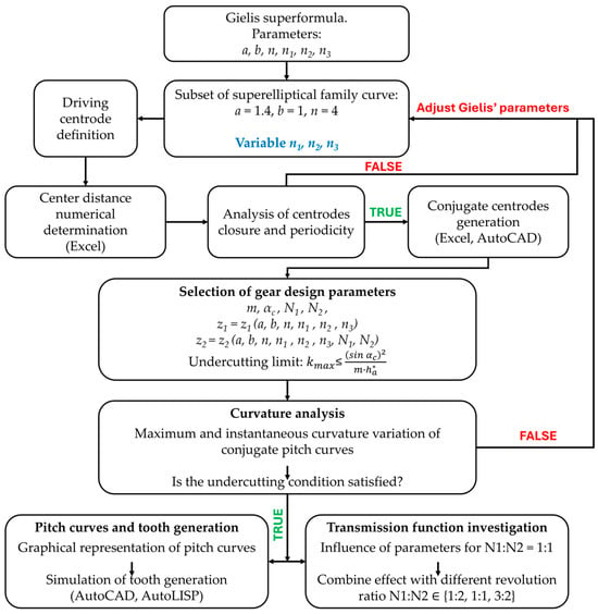
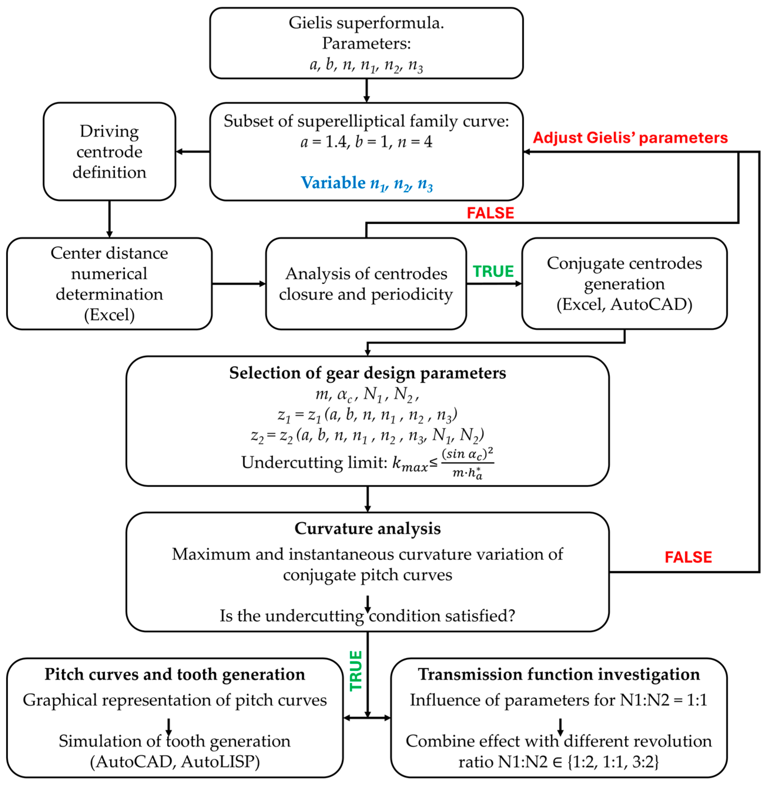
Figure 3 synthetically illustrates the workflow of the proposed research methodology, illustrating the successive stages of the geometric synthesis, numerical investigation and validation of the generated non-circular gears. The diagram summarizes the successive stages of the investigation and is not intended to represent the execution flow of the computational implementation.
Figure 3.
Overview of the successive stages of the proposed research methodology.
3. Results and Discussion
3.1. Conjugate Pitch Curve’s Closure
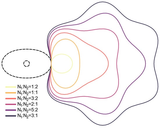
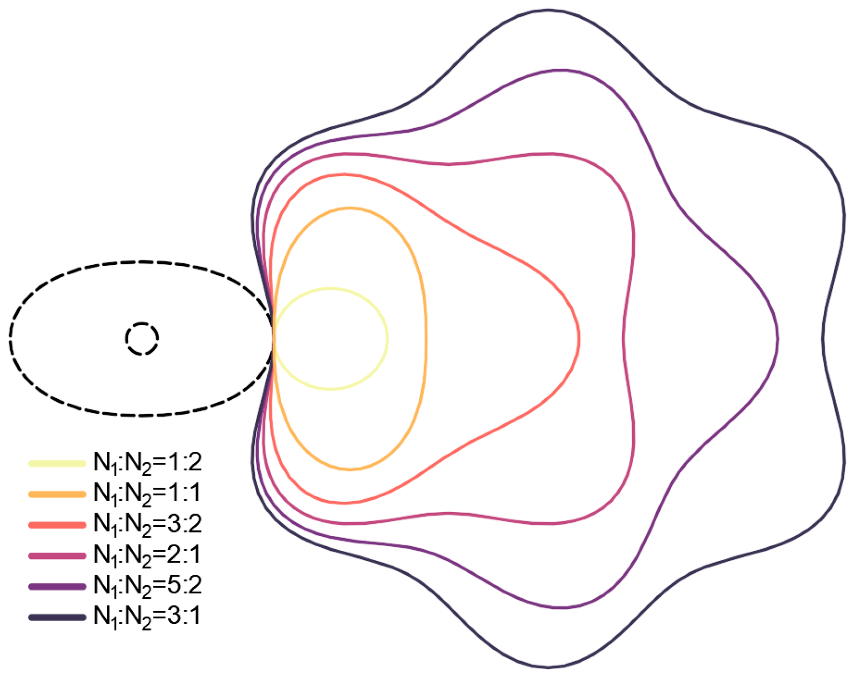
Numerical investigations and geometric representations of the conjugate centrodes, in the general case of performing N1 and N2 revolutions, respectively, over one rotation period, have shown that, in order to get a closed driven centrode, the ratio of the related revolutions, N1:N2, must be proportional to the geometric periodicity of the driving centrode; specifically, if the driving centrode has n sectors of rotational symmetry, the revolution ratio should be a rational multiple of 2/n. In Figure 4, a driving centrode, represented as a conventional normalized ellipse (n = 4), selected from the Gielis’ supershapes, in the case of a = 1.4, b = 1, n1 = n2 = n3 = 2 is illustrated; its driven centrode is also a closed curve, as long as the ratio of the related revolutions N1:N2 is a multiple of 2/4 = 0.5. The examples shown in Figure 4 confirm that the proposed closure criterion successfully predicts the existence of closed conjugate centrodes for different revolution ratios and enables the admissibility of the revolution ratio to be verified before tooth generation, thereby preventing the synthesis of non-closed conjugate pitch curves.
Figure 4.
Close driving centrode and its close conjugate driven centrodes, for different gear ratios.
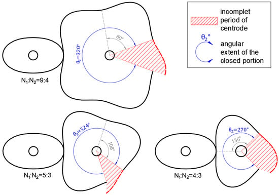
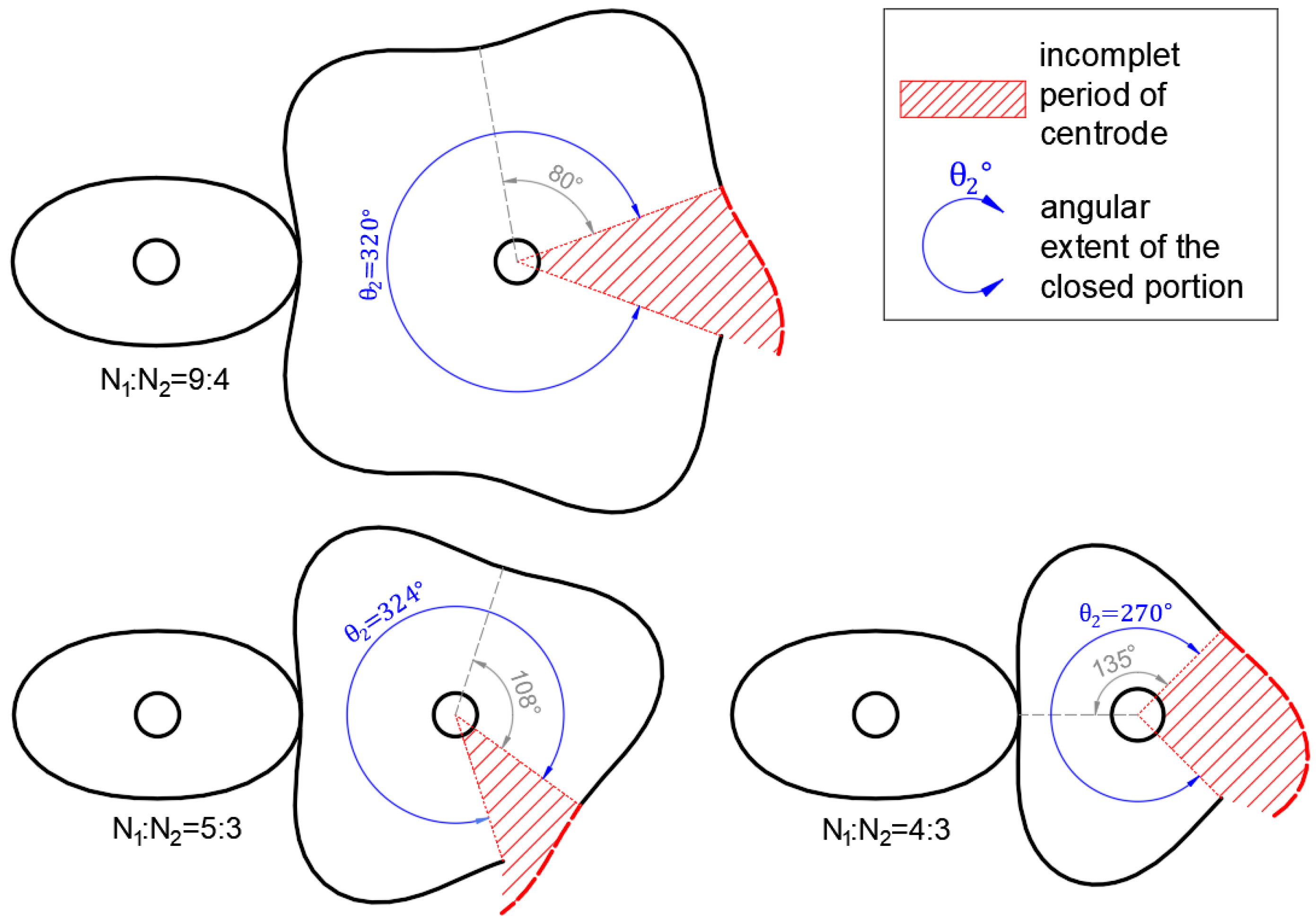
Conversely, when the revolution ratio does not satisfy the proposed closure criterion, the generated driven centrode remains open and exhibits an incomplete lobe, as illustrated in Figure 5. The angular extent of the open driven centrode, excluding the incomplete segment, is given by:
where represents the angular period of the driven centrode, while denotes the integer number of complete periods generated during one revolution.
Figure 5.
Open driven conjugate centrodes resulting from non-admissible revolution ratios. Chosen Gielis’ superformula parameters: a = b = 1, n = 4, n1 =1.25, n2 = n3 = 2.
Unlike the admissible revolution ratios shown in Figure 4, the selected non-admissible ratios generate driven centrodes containing an incomplete period, preventing curve closure. Equation (32) predicts the angular extent of the complete portion of the driven centrode and, consequently, the remaining incomplete segment. Therefore, the proposed criterion provides a simple and efficient means of identifying admissible revolution ratios before performing the subsequent stages of gear synthesis and tooth generation.
Taken together, Figure 4 and Figure 5 demonstrate that the proposed closure criterion provides both the necessary and sufficient condition for obtaining closed driven centrodes within the adopted design framework. Moreover, the closure condition significantly enlarges the design space by allowing multiple admissible revolution ratios for the same driving pitch curve, each producing a distinct driven-centrode geometry.
3.2. Parametric Investigation on Geometric Features
To analyze the influence of the defining parameters on the geometry of the conjugate non-circular pitch curves, whose driving component derives from the Gielis’ modified ellipses, a particular gears train is considered. For a predesigned semi-axis length of the normalized driving centrode, a = 1.4 mm, the driving gear’s number of teeth z1 = 36 would comply with the undercut avoidance requirement (Figure 2); as the choice of the gears’ modulus is not limited by any geometrical or technological constraints, the value m = 3 mm is considered. As a result, the conjugate normalized centrodes (Equations (14)–(17)) are properly scaled (Equation (19)) and redefined as pitch curves for the modified elliptical gears, imposing several gear revolution ratios.
The results are presented progressively. First, the dependence of the maximum curvature on the superformula parameters (n1, n2, n3) is established for the three revolution ratios N1:N2 ∈ {1:2, 1:1, 3:2}. The limiting parameter values associated with undercutting are then identified and used to evaluate the instantaneous curvature distributions for driving gear. For each limiting case, the corresponding conjugate pitch curves are presented together with the instantaneous curvature variation of the driven gear.
For each parameter configuration, the geometric characteristics were obtained by numerical evaluation of the analytical equations presented in Section 3. The resulting datasets were processed in Microsoft Excel to determine the quantities of interest and to generate the corresponding plots. The pitch curves and the gear tooth profiles are represented graphically in the AutoCAD environment, based on specifically developed AutoLISP routines.
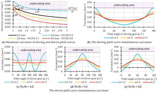
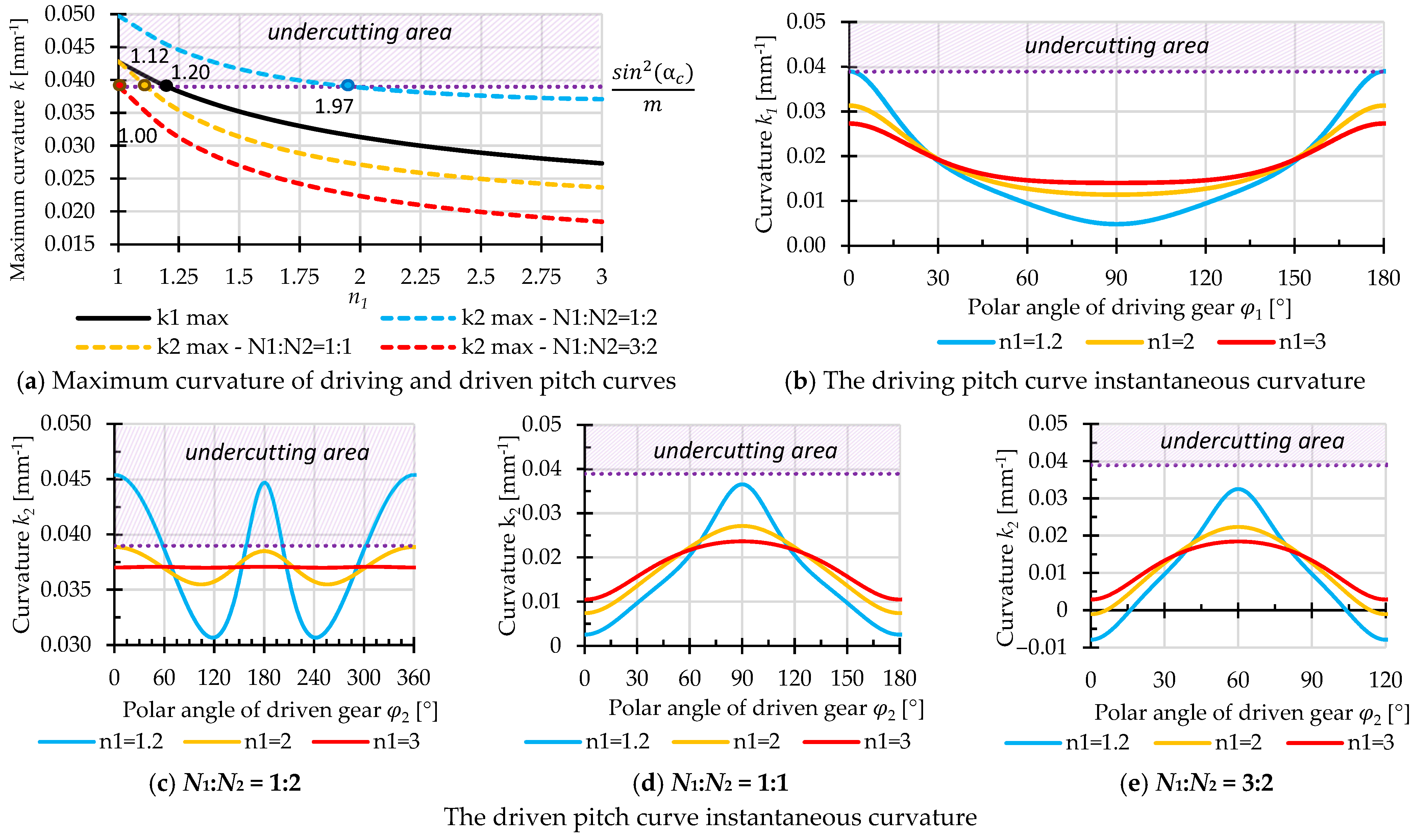
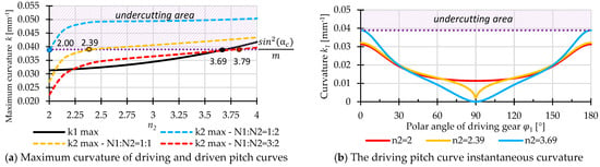
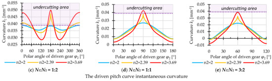
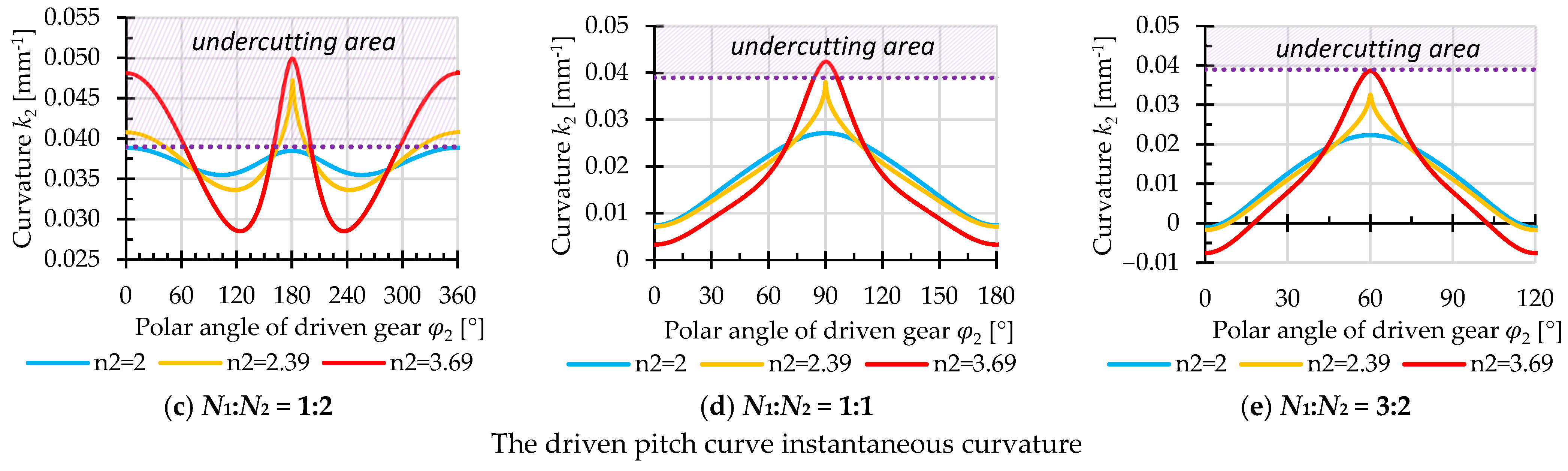
Varying the parameter n1, the curve’s global smoothing exponent, in the vicinity of “standard ellipse” value (n1 = 2), it is confirmed that the maximum curvature decreases with increasing values of n1 (Figure 6a). Related to the “undercutting limit”, it appears that the minimum admissible value to be chosen when designing the driving centrode, for 1:1 revolutions’ ratio, is n1 = 1.20; this value appears to be also a convenient one, referring to the maximum curvature of the driven centrode, as long as the revolutions’ ratio is a real number greater than 1. In the case where the ratio N1:N2 is less than 1, the driven centrode geometry imposes the minimum admissible value for the n1 parameter; as seen in Figure 6a, for N1:N2 = 1:2, the global exponent-parameter should be n1 ≥ 1.97 to avoid undercutting on the driven gear.
Figure 6.
Numerically computed curvature variations of the analyzed conjugate pitch curves as a function of n1 parameter. Input data: a = 1.4, b = 1, n = 4, n2 = n3 = 2, m = 3 mm, z1 = 36, z2 ∈ {18, 36, 54}.
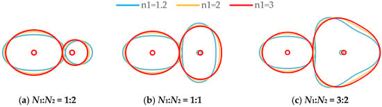
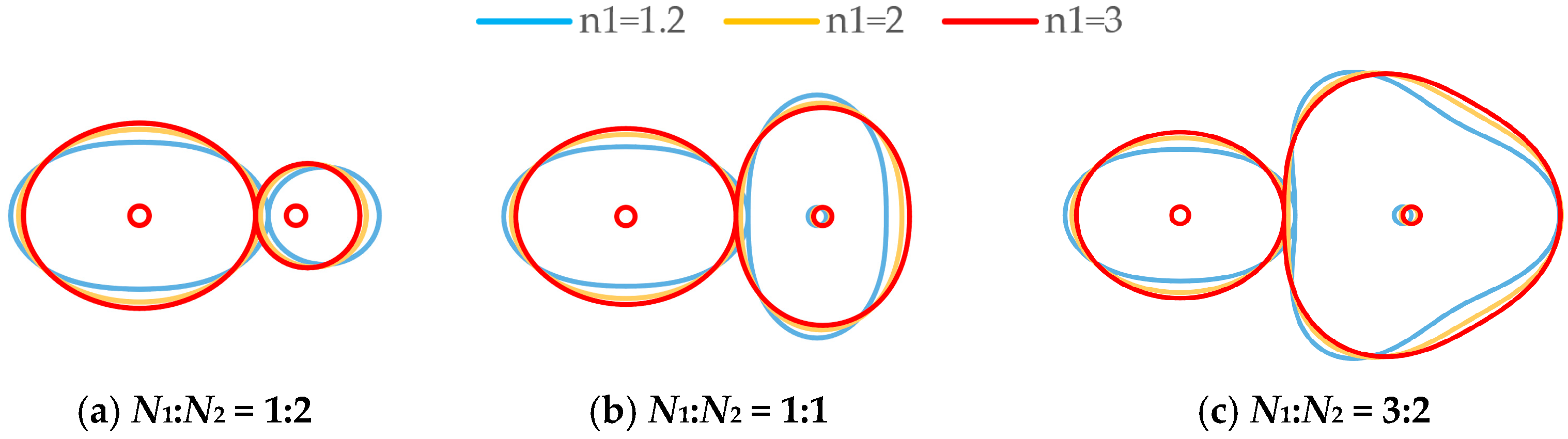
Due to the function’s periodicity, the driving pitch curve curvature is analyzed within the angular periodicity φ1 ∈ [0, 180°]. As seen in Figure 6b, the curvature reaches its maximum values at 0° and 180°; as the parameter value increases, the variation of the curvature decreases, describing a geometrically smoother and more uniform curve. Figure 6c–e illustrates the influence of the Gielis’ global exponent on the curvature and geometry of the driven pitch curves, corresponding to different revolution ratios. As is increased, the curvature distribution becomes progressively more uniform, while the maximum curvature values decrease. This effect is particularly important for the prevention of undercutting, since larger values of move the curvature peaks further from the limiting value. The geometric consequence of this trend can be observed in the corresponding pitch curves, which evolve from more elongated and highly curved shapes toward smoother and more regular profiles (Figure 7).
Figure 7.
Conjugate pitch curves geometries as functions of n1 parameter. Input data: a = 1.4, b = 1, n = 4, n2 = n3 = 2, m = 3 mm, z1 = 36, z2 ∈ {18, 36, 54}.
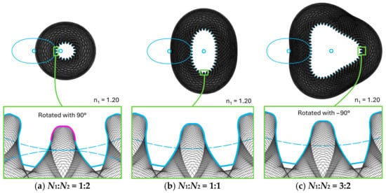
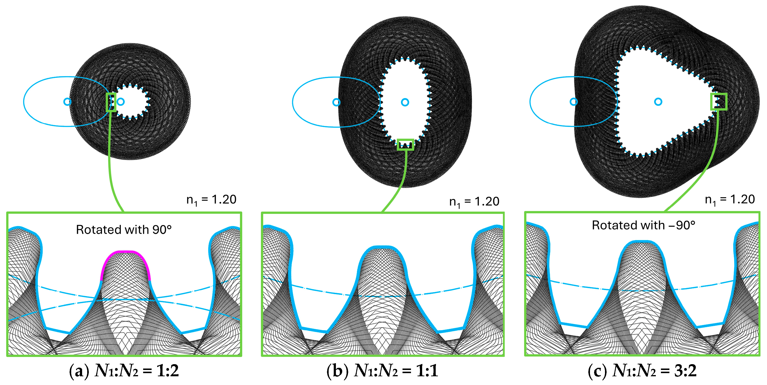
Proceeding further and simulating the gear tooth generation, using a gear shaper cutter with standard geometry, the tooth flanks of the non-circular gears are obtained as the envelope of the successive positions of the cutter, during the rolling motion inherent to the generating process. Using the AutoCAD graphical facilities and original AutoLISP codes, the simulation of the gear generation provided an illustrative validation of the potential tooth undercutting phenomenon, in the regions where the curvature of the pitch curve indicated the potential occurrence of this effect (Figure 8).
Figure 8.
Tooth profile of driven gear in maximum curvature zone. Input data: a = 1.4, b = 1, n = 4, n1 = 1.2, n2 = n3 = 2, m = 3 mm, z2 ∈ {18, 36, 54}, αc = 20°.
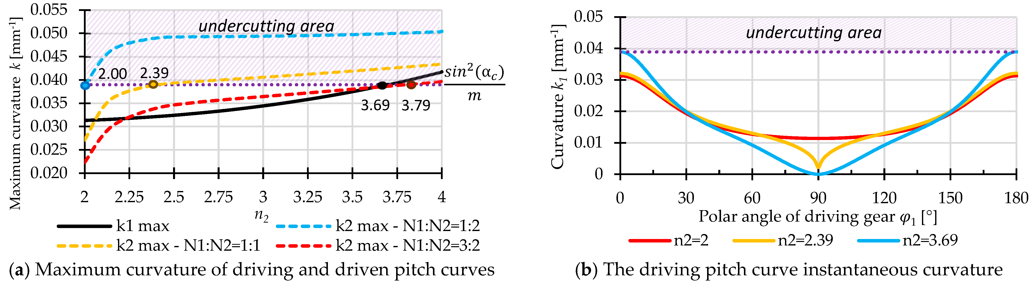
Figure 9 illustrates the variation of the maximum curvatures as functions of the n2 parameter. For the selected semi-axis ratio (a/b = 1.4), increasing n2 beyond the value associated with the conventional elliptical geometry (n2 = 2) leads to a gradual increase in the driving pitch curve curvature, with the onset of undercutting occurring only at nearly twice this value. In contrast, the geometry of the driven pitch curve is more restrictive, as its curvature rises sharply in the vicinity of n2 = 2, followed by a significantly lower rate of increase. For a revolution ratio of N1:N2 = 1, an increase of slightly more than 20% in n2 is already sufficient to compromise the geometry of the driven pitch curve, leading it into the undercutting region (Figure 9a). Larger variations of n2 and consequently of the pitch curve curvature may be achieved by increasing the number of revolutions of the driving gear. The results highlight that the feasible design domain is primarily constrained by the driven centrode and indicate low admissible values of n2.
Figure 9.
Numerically computed curvature variations in the analyzed conjugate pitch curves as a function of n2 parameter. Input data: a = 1.4, b = 1, n = 4, n1 = n3 = 2, m = 3 mm, z1 = 36, z2 ∈ {18, 36, 54}.
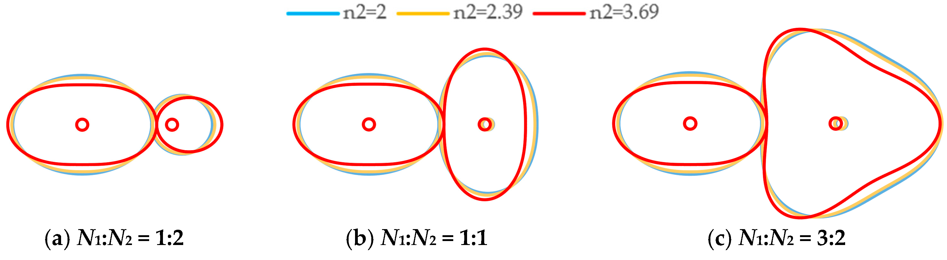
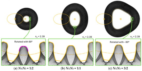
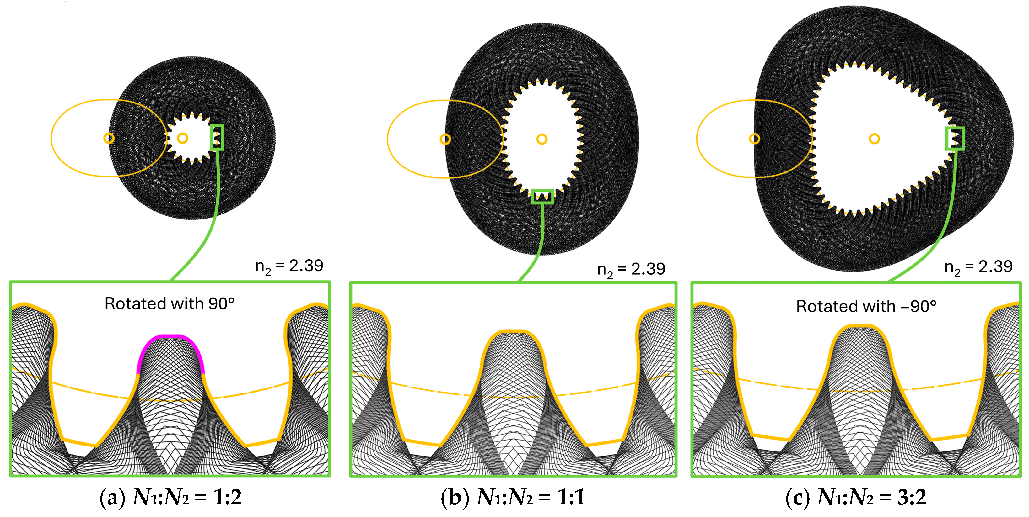
In Figure 10, the driven gear tooth flanks are illustrated, detailing critical zones where the undercut phenomenon appears (Figure 11) or the tooth geometry is modified in correspondence to the centrode’s local curvature.
Figure 10.
Conjugate pitch curves geometries as functions of n2 parameter. Input data: a = 1.4, b = 1, n = 4, n1 = n3 = 2, m = 3 mm, z1 = 36, z2 ∈ {18, 36, 54}.
Figure 11.
Tooth profile of driven gear in maximum curvature zone. Input data: a = 1.4, b = 1, n = 4, n1 = 2, n2 = 2.39, n3 = 2, m = 3 mm, z2 ∈ {18, 36, 54}, αc = 20°.
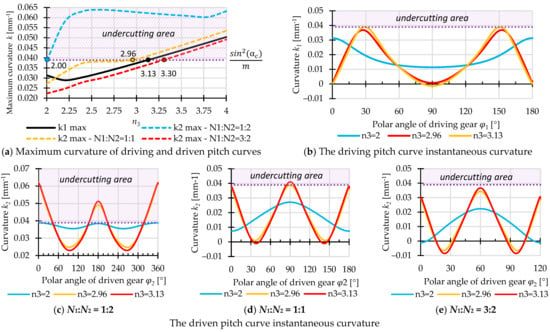
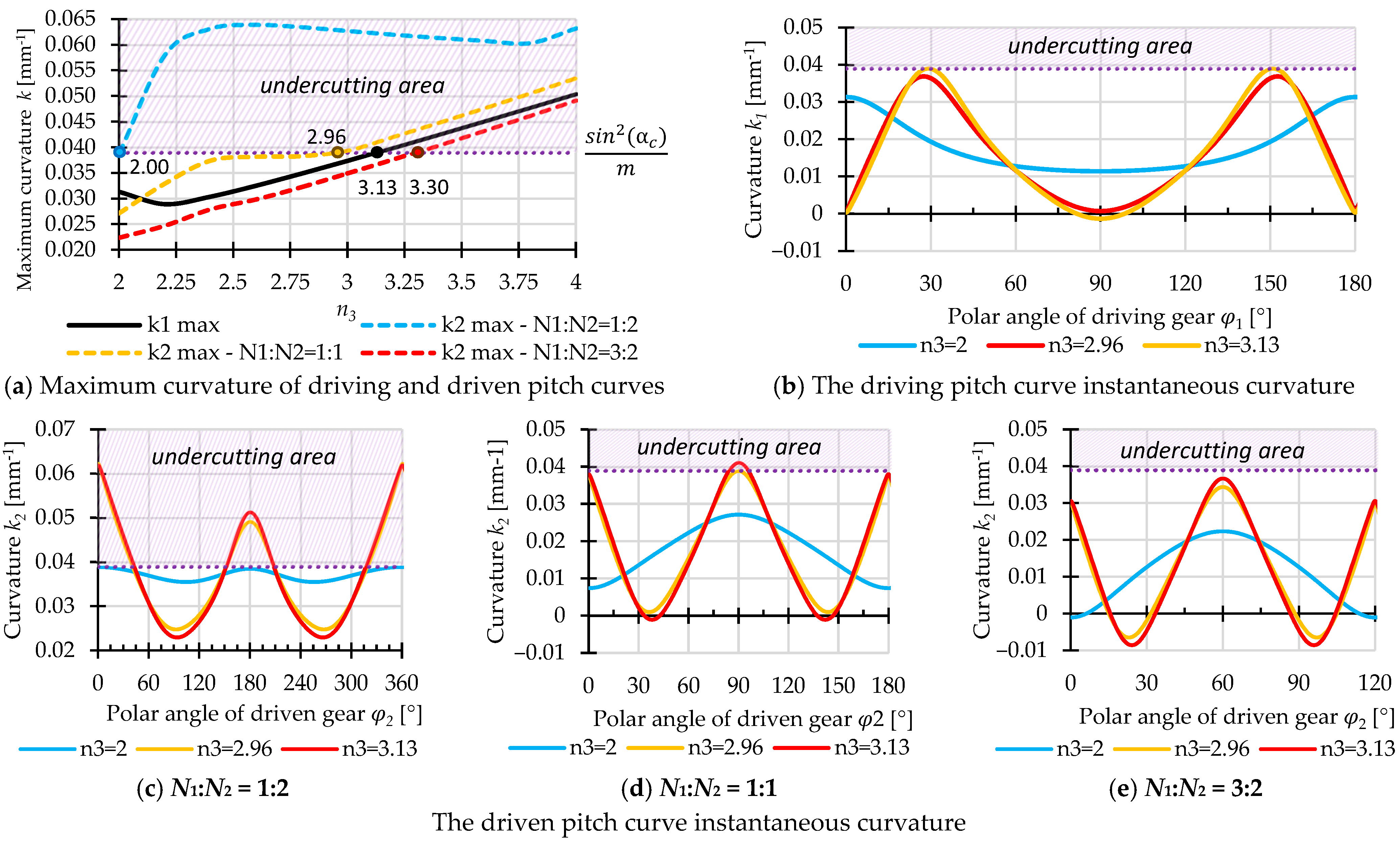
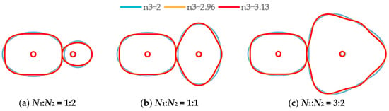
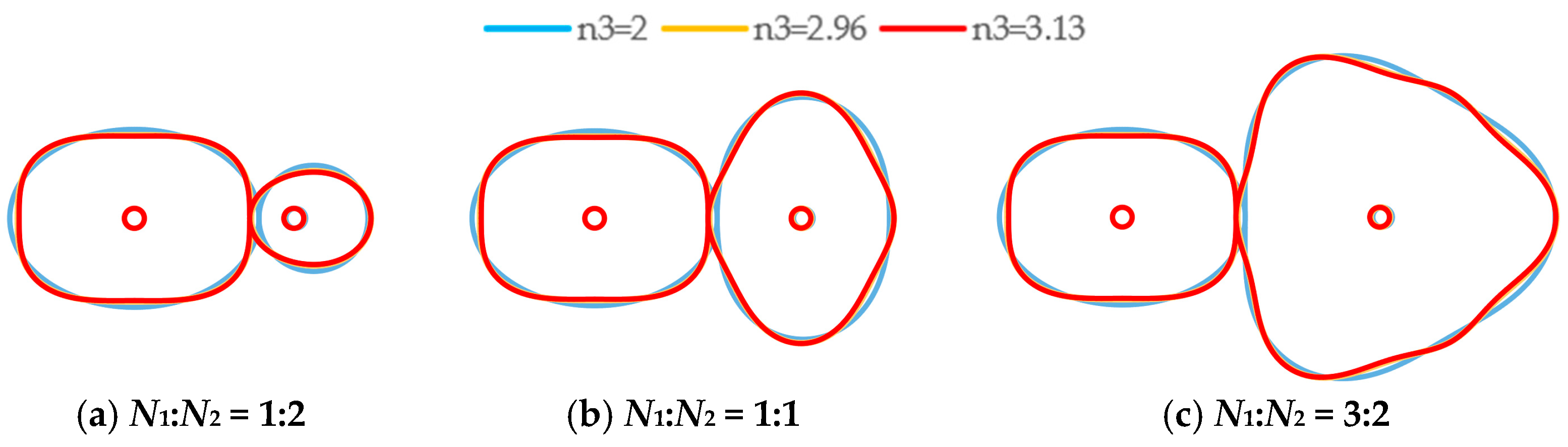
The influence of Gielis’ superformula exponent n3 differs from that of the previously analyzed parameters. This parameter primarily affects the distribution of curvature along the pitch curves rather than their overall dimensions. The numerical results reveal a trade-off between the curvature of the driving and driven pitch curves. Increasing n3 reduces the maximum curvature of the driven centrode while simultaneously increasing that of the driving centrode. It can be noticed that the value of represents a balanced design solution, for which the maximum curvatures of the driving and driven pitch curves become approximately equal. Consequently, the admissible value of n3 should be selected according to the design objective and the gear on which undercutting is more likely to occur. As shown in Figure 12b, increasing n3 progressively transforms the curvature profile of the driving centrode from a relatively smooth distribution into one characterized by distinct local maxima and minima. This behavior indicates a gradual concentration of curvature within specific angular regions.
Figure 12.
Numerically computed curvature variations of the analyzed conjugate pitch curves as a function of n3 parameter. Input data: a = 1.4, b = 1, n = 4, n1 = n2 = 2, m = 3 mm, z1 = 36, z2 ∈ {18, 36, 54}.
A similar tendency can be observed for the driven centrodes (Figure 12c,e), where increasing n3 amplifies the contrast between high-curvature and low-curvature regions. Consequently, the generated geometries evolve from nearly elliptical shapes toward profiles with more pronounced lobes and sharper geometric transitions. This effect is particularly evident for the 1:1 and 3:2 revolution ratios, where the outer contour departs significantly from the reference geometry as n3 is increased. The corresponding pitch curves shown in Figure 13 illustrate that the parameter n3 provides an effective means of controlling the prominence of the lobes while preserving the overall symmetry of the centrodes.
Figure 13.
Conjugate pitch curves geometries as functions of n3 parameter. Input data: a = 1.4, b = 1, n = 4, n1 = n2 = 2, m = 3 mm, z1 = 36, z2 ∈ {18, 36, 54}.
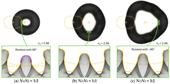
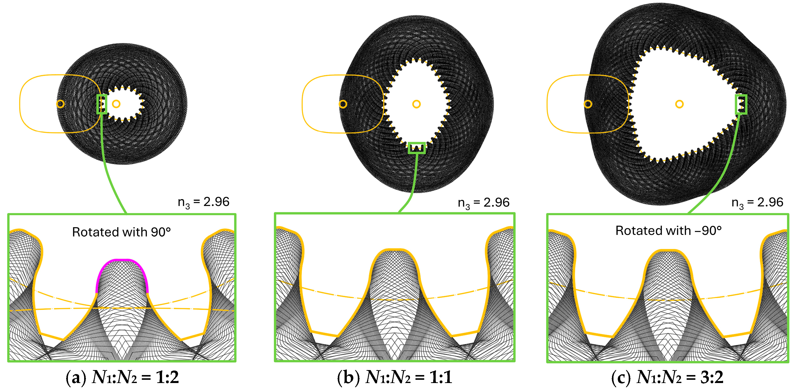
The generated tooth profiles are additionally represented in Figure 14. This graphical representation complements the curvature analysis by providing a direct visualization of the generated tooth geometry. The undercut portions of the tooth flanks were highlighted in magenta to facilitate their identification. The generated tooth profiles are represented in the regions of maximum curvature of the driven pitch curve.
Figure 14.
Tooth profile of driven gear in maximum curvature zone. Input data: a = 1.4, b = 1, n = 4, n1 = 2, n2 = 2, n3 = 2.96, m = 3 mm, z2 ∈ {18, 36, 54}, αc = 20°.
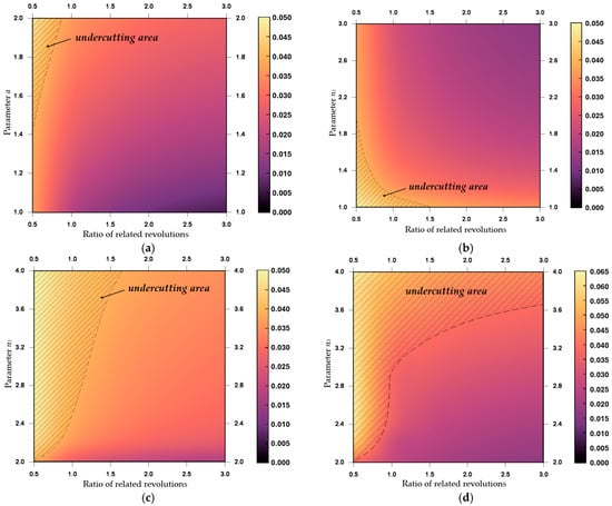
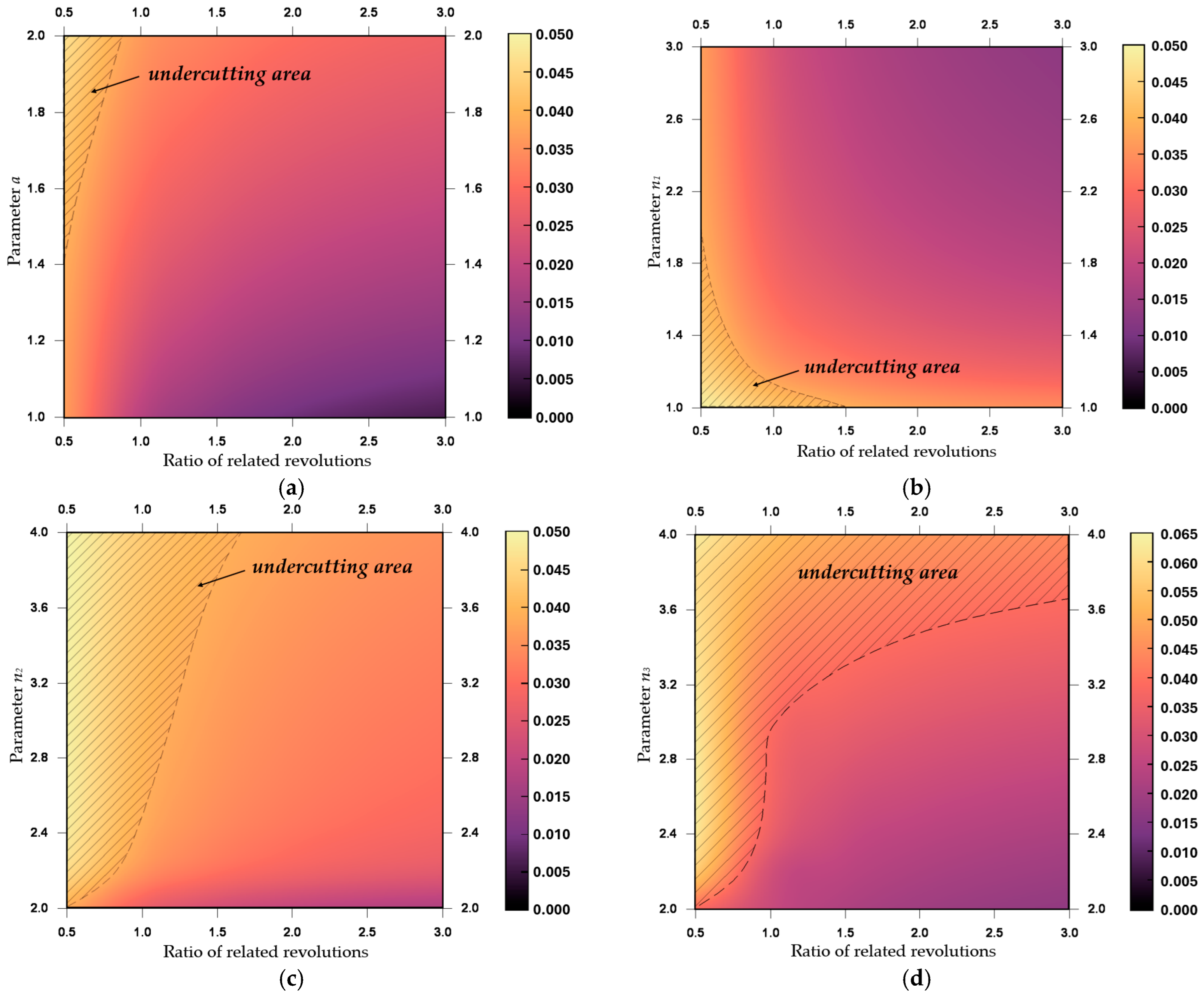
The individual analyses presented describe the influence of each Gielis parameter separately. From a practical design perspective, the selection of a suitable parameter combination requires a simultaneous evaluation of both the superformula parameters and the revolution ratio. For this purpose, generalized parametric maps were generated to identify the admissible design domains according to the maximum curvature criterion.
Figure 15 summarizes the coupled influence of the revolution ratio and each Gielis’ parameter on the maximum curvature of the driven pitch curve. To reduce the number of unknowns, parameter b = 1 is selected for all cases. For each diagram, one parameter is varied while the remaining parameters are kept at constant values. The shaded regions indicate parameter combinations for which the maximum curvature exceeds the undercutting limit, whereas the remaining domains correspond to geometries that can be generated without undercutting.
Figure 15.
Parametric design maps illustrating the influence of the Gielis parameters and the revolution ratio on the maximum curvature of the driven pitch curve. The remaining parameters are kept constant in each subplot: (a) n1 = n2 = n3 = 2, (b) a = 1.4, n2 = n3 = 2, (c) a = 1.4, n1 = n3 = 2, (d) a = 1.4, n1 = n2 = 2.
For all cases, consistent with the previous observations, the maximum curvature values of the driven centroid decreases as the revolution ratio increases. Increasing parameters and amplifies the centroid curvature, while parameter produces the opposite effect, as its increase leads to smoother, more rounded shapes.
Unlike the individual curvature plots presented previously, the proposed maps provide a direct design tool. They allow the designer to identify feasible parameter combinations at an early stage of the synthesis procedure, eliminating parameter sets that would inevitably lead to undercutting before the tooth generation process is performed. These colormaps should be interpreted as design-assistance tools rather than optimization charts.
3.3. Parametric Investigation on Transmission Ratio Variation
A parametric transmission ratio sensitivity analysis is further conducted for the gears previously generated, by varying one Gielis’ superformula parameter at a time while maintaining all other parameters constant.
Since the driving pitch curve, selected from the family of superellipses, exhibits periodic behavior, the transmission ratio function is inherently periodic as well, with a period equal to π. Therefore, the analysis of the transmission ratio variation can be restricted to the investigation of the function amplitude and of any deviations from the characteristic sinusoidal behavior.
Two complementary scenarios are considered in order to investigate the variation of the transmission ratio function. The first scenario focuses on the influence of the Gielis’ superformula parameters on the function amplitude, for the most common case encountered in industrial applications, namely the unity ratio between the numbers of revolutions performed by the driving and driven gears over one operating period (N1:N2 = 1:1). The second scenario investigates the influence of the revolution ratio over one period on the amplitude of the transmission ratio function, considering the variable Gielis parameters values that lead to pronounced deviations from the ideal transmission ratio function.
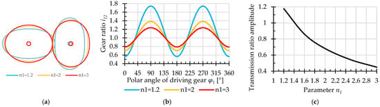
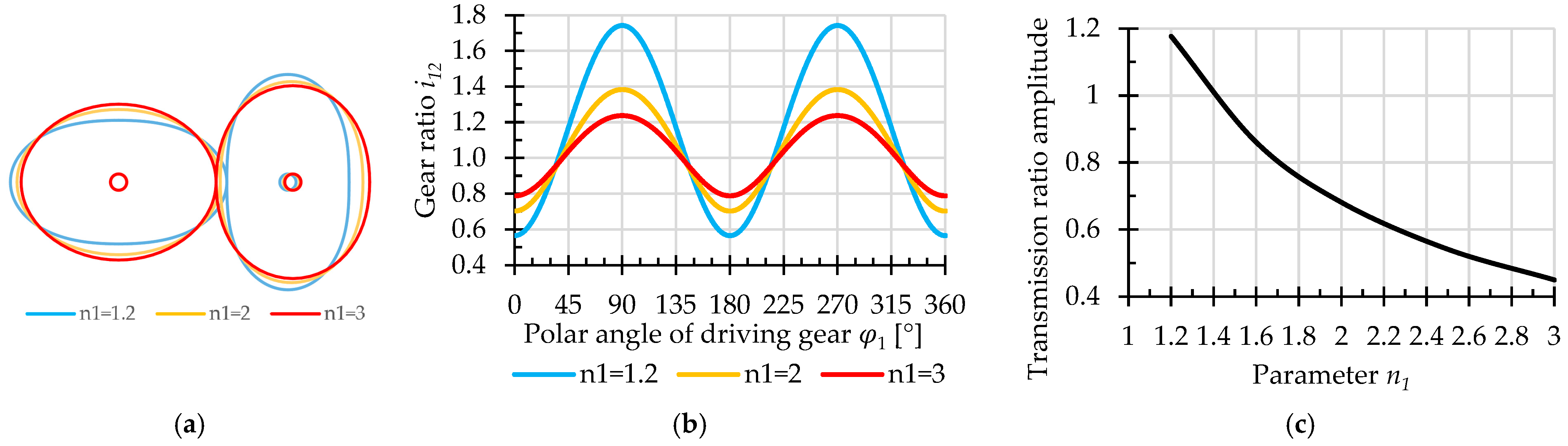
In Figure 16b, the influence of the Gielis exponent on the transmission/gear ratio variation is presented. Increasing the parameter value raises the minimum transmission ratio while simultaneously reducing the variation range of the transmission ratio function. In addition, the rate of change of the transmission ratio becomes less pronounced. These results are intuitive, since significant curvature variations, as the n1 parameter is decreased, tend to be accompanied by increased transmission ratio gradients. As n1 is increased, the driving pitch curve progressively approaches a circular shape, leading to an asymptotic reduction of the transmission ratio amplitude and, consequently, to a constant transmission ratio (Figure 16c). From an industrial perspective, the increase in the n1 exponent value, generating the increase in the minimum transmission ratio, reduced amplitude and lower rate of variation of the transmission ratio function, results in smoother kinematic behavior and less severe dynamic loading conditions.
Figure 16.
The transmission ratio, as function of n1 parameter. (a) Illustration of the conjugate pitch curves. (b) Transmission ratio variation, in accordance with the conjugate pitch curves geometry. (c) Transmission ratio amplitude. Input data: a = 1.4, b = 1, n = 4, n2 = 2, n3 = 2, N1:N2 = 1:1.
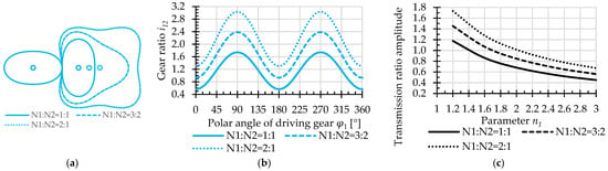
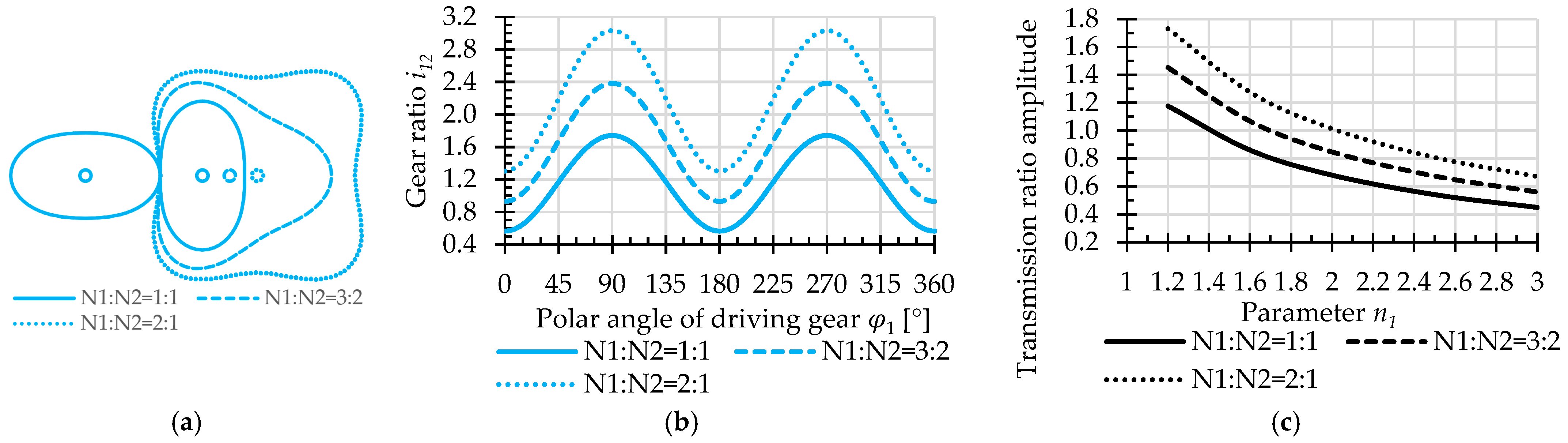
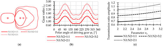
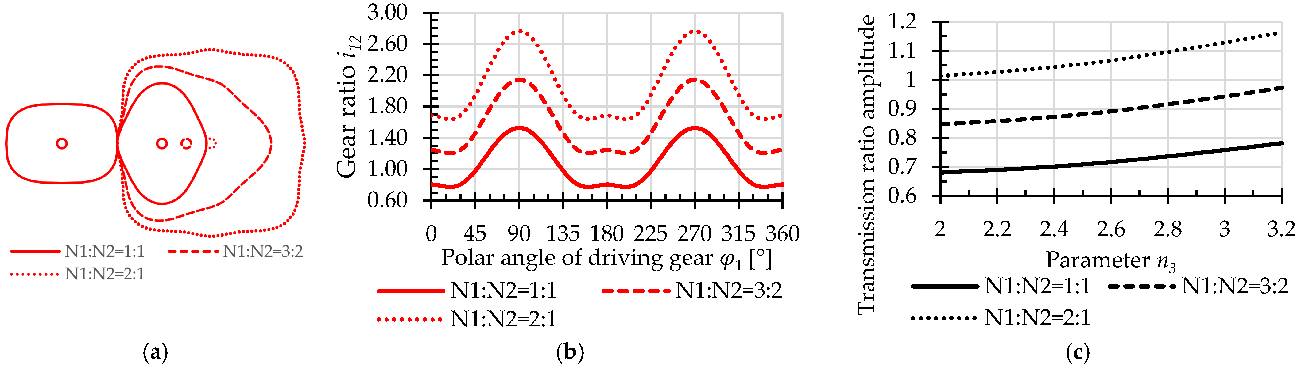
As a complement to the previous analysis, considering the same value of parameter n1 while varying the kinematic parameter, namely the gears revolution ratio, N1:N2, the numerical results reveal that the revolution ratio has a primary effect of shifting the entire transmission ratio range towards higher values (Figure 17b) and a relatively minor influence on the amplitude and the rate of variation of the transmission ratio (Figure 17). This behavior can be explained by the fact that the revolution ratio primarily affects the mean value of the transmission ratio, while the shape of the transmission ratio function remains mainly governed by the geometry of the driving pitch curve.
Figure 17.
The transmission ratio, as function of N1:N2 parameter. (a) Illustration of the conjugate pitch curves. (b) Transmission ratio variation. (c) Transmission ratio amplitude. Input data: a = 1.4, b = 1, n = 4, n1 = 1.2, n2 = 2, n3 = 2.
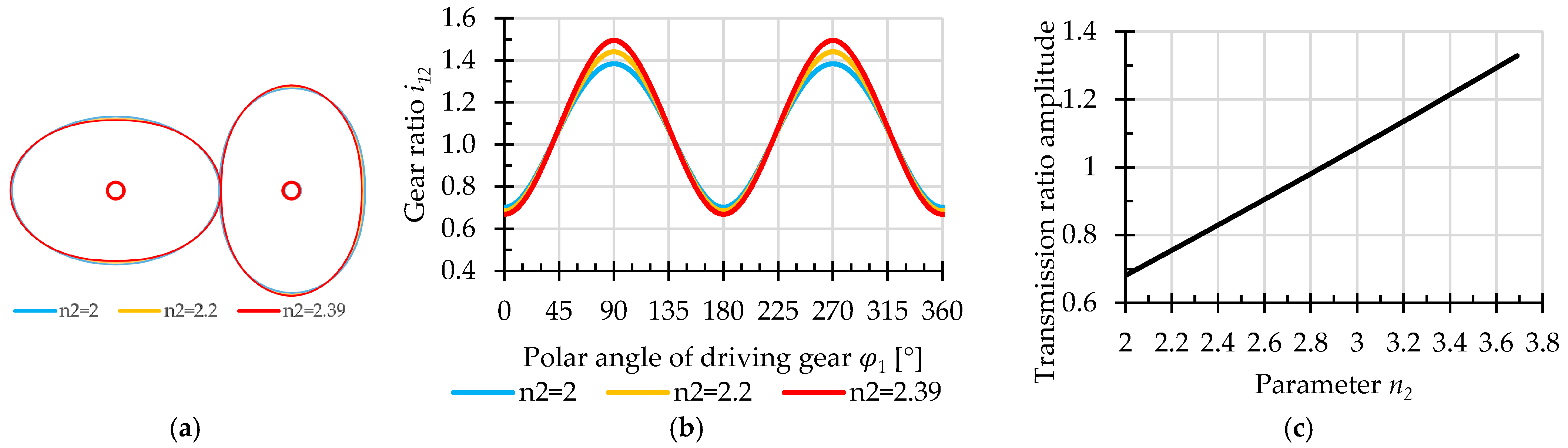
The Gielis’ superformula exponent n2 controls the curvature associated with the cosine term from the Gielis’ superformula. As shown in Figure 9, the variation of this parameter is highly restricted by the geometry of the driven pitch curve. In the particular case analyzed, with a semi-axis ratio of the driving elliptical pitch curve of a/b = 1.4 and the ratio N1:N2 = 1:1, the maximum admissible increase of approximately 20% in the parameter n2 produces only negligible deviations of the conjugate pitch curve geometries from their conventional elliptical counterparts, with similarly insignificant consequences on the transmission ratio. In general, an increasing parameter value tends to decrease the value of the minimum transmission ratio, whereas its amplitude increases approximately linearly over the investigated parameter range (Figure 18).
Figure 18.
The transmission ratio, as function of n2 parameter. (a) Illustration of the conjugate pitch curves. (b) Transmission ratio variation, in accordance with the conjugate pitch curves. (c) Transmission ratio amplitude. Input data: a = 1.4, b = 1, n = 4, n1 = 2, n3 = 2, N1:N2 = 1:1.
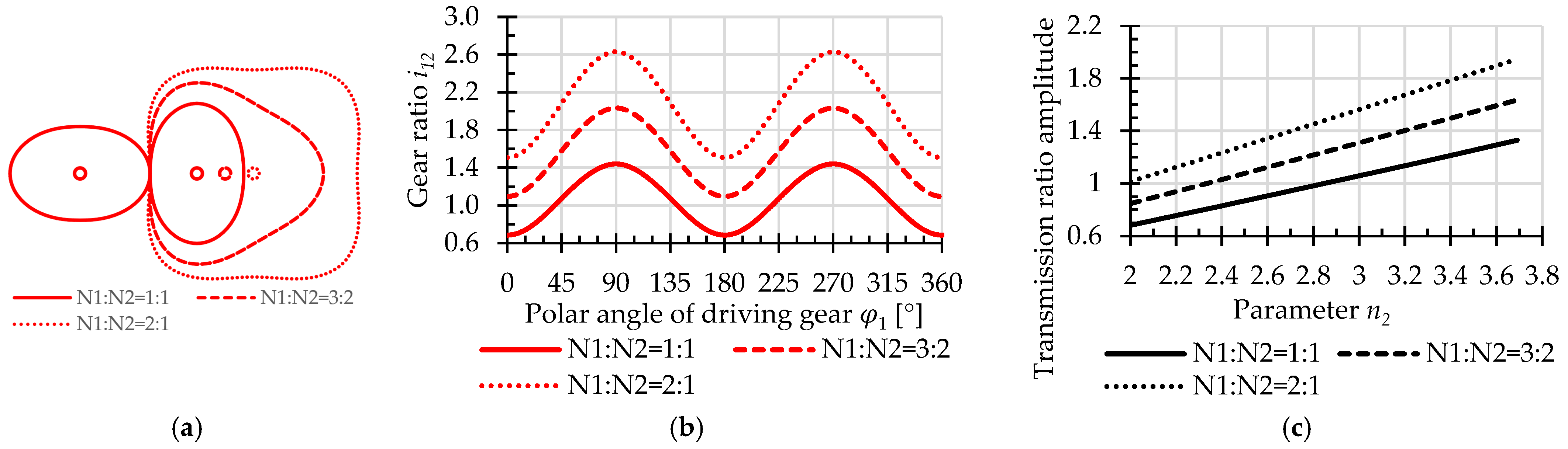
Considering additionally the effect of the gear’s revolution ratio on the transmission ratio, a behavior similar to that observed in the previous case is obtained (Figure 19). The minimum and mean transmission ratio values increase with increasing rrevolution ratio while the rate of variation exhibits trends like those corresponding to the conventional case, N1:N2 = 1:1. The explanation is analogous to that corresponding to parameter : the revolution ratio mainly shifts the transmission ratio function towards higher values, while preserving similar variation patterns.
Figure 19.
The transmission ratio, as function of N1:N2 parameter. (a) Illustration of the conjugate pitch curves. (b) Transmission ratio variation. (c) Transmission ratio amplitude. Input data: a = 1.4, b = 1, n = 4, n1 = 2, n2 = 2.39, n3 = 2.
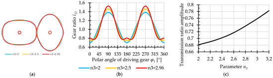
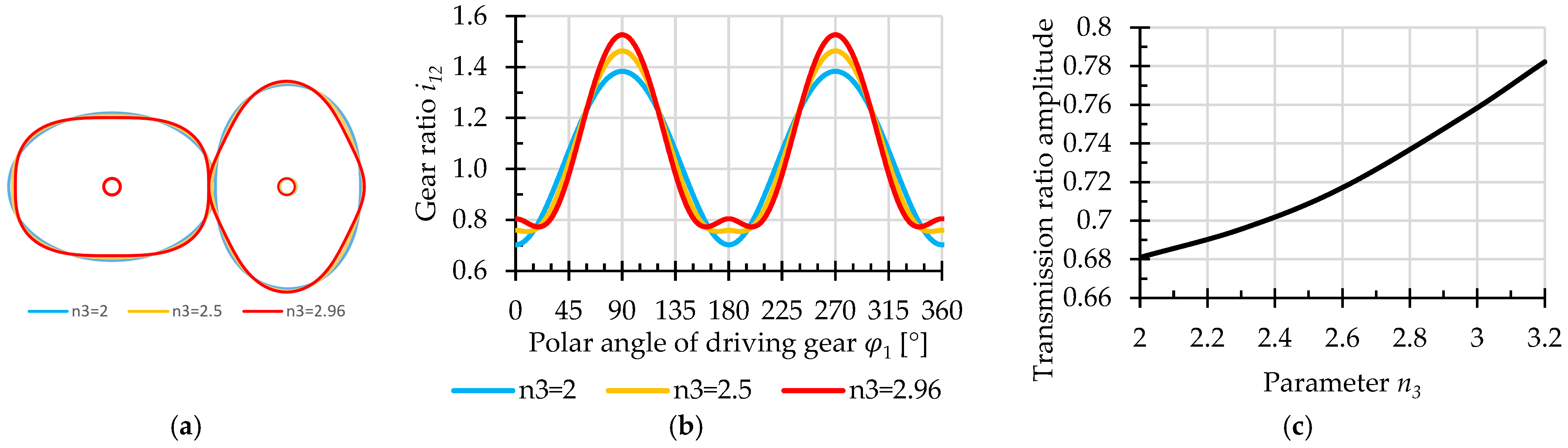
The parameter n3, associated with the sine term from the Gielis’ superformula, acts similarly to n2 but influences the complementary curvature regions of the centrode. As can be seen in Figure 20, the increase in the parameter n3 also leads to an increase in the amplitude of the transmission ratio, but at lower rate than its counterpart, n2. In addition, due to the appearance of a new local maximum in the curvature of the pitch curves, local maxima also appear in the transmission ratio, becoming more pronounced as n3 is increased. For a fixed n3 = 2.96, modifying the revolution ratio N1:N2 again scales the amplitude of the transmission ratio (Figure 21).
Figure 20.
The transmission ratio as function of n3 parameter. (a) Illustration of the conjugate pitch curves. (b) Transmission ratio variation, in accordance with the conjugate pitch curves. (c) Transmission ratio amplitude. Input data: a = 1.4, b = 1, n = 4, n1 = 2, n2 = 2, N1:N2 = 1:1.
Figure 21.
The transmission ratio as function of N1:N2 parameter. (a) Illustration of the conjugate pitch curves. (b) Transmission ratio variation. (c) Transmission ratio amplitude. Input data: a = 1.4, b = 1, n = 4, n1 = 2, n2 = 2, n3 = 2.96.
4. Conclusions
The proposed methodology demonstrates that the Gielis superformula provides a unified analytical framework for the generation and investigation of non-circular gear pitch curves. The numerical investigations confirmed that suitable combinations of the superformula parameters enable the synthesis of admissible conjugate centrodes satisfying the principal geometric requirements for non-circular gears, including closure, periodicity, smooth curvature and the avoidance of undercutting.
To illustrate the study procedure, the proposed methodology and the resulting findings, the investigation was carried out for the case of driving pitch curves defined as generalized ellipses; from this perspective, the present work can be readily compared with similar studies based on other defining equations of elliptical pitch curves. The adopted assumption involved assigning specific values to some of the Gielis’ superformula parameters, namely the parameter controlling the rotational symmetry of the curve and the semi-axis ratio of the corresponding conventional ellipse; as a consequence, only three variable parameters defining the geometry of the conjugate centrodes were retained in the analysis—the Gielis’ superformula exponents. With regard to the gear-specific parameters, the selection of the module, the number of teeth, and the revolution ratio of the gears was likewise parametrized and guided by undercutting avoidance considerations.
The performed one-factor-at-a-time analysis highlighted that the governing parameters influence the gear geometry in different ways. The parameters n1 and n3 primarily control the global shape of the pitch curves and therefore represent the principal design parameters during the synthesis process. Among the investigated parameters, n2 produces the largest curvature concentrations and consequently represents the most restrictive parameter with respect to undercutting.
The curvature analysis identified the admissibility limits associated with the investigated parameter variations, providing design guidelines for selecting parameter combinations that satisfy the imposed geometric constraints. The proposed curvature maps constitute practical design charts, allowing unsuitable parameter combinations to be eliminated before the tooth generation stage. The results further showed that the revolution ratio significantly affects the curvature of the driven pitch curve; increasing N1:N2 reduces the maximum curvature and consequently enlarges the admissible design domain, whereas lower revolution ratios impose more restrictive design conditions. The generated gear models confirmed the feasibility of the proposed design procedure. The obtained tooth geometries provided a direct validation of the curvature-based undercutting criterion.
The analysis of the transmission ratio demonstrated that the superformula parameters modify both the amplitude and the shape of its instantaneous variation. In particular, the n1 parameter had the greatest influence on the overall transmission law, whereas n3 mainly affects its local evolution. Therefore, the proposed methodology enables the kinematic characteristics of the gear pair to be adjusted according to the functional requirements without changing the mathematical formulation of the pitch curves.
The proposed methodology is intended as a general design framework. The numerical examples presented in this work illustrate its application to a representative case study and are not intended to define universal optimal parameter values. The final parameter selection remains application-dependent and should be performed according to the prescribed transmission ratio characteristics and the associated geometric constraints.
Further work could involve the presented methodology as a practical design tool for the parametric synthesis of superelliptical non-circular gears and can be readily extended to other families of parametric pitch curves, with convex–concave geometries, symmetric or asymmetric shapes. Future developments will therefore focus on extending the proposed framework to broader classes of Gielis-based curves, as well as on investigating tooth-root strength, contact stresses, load distribution, efficiency and dynamic behavior for specific engineering applications. These developments are expected to extend the proposed generalized design framework from geometric synthesis toward the complete engineering design of application-oriented non-circular gear transmissions.
Author Contributions
Conceptualization, P.-A.P. and L.A.; methodology, L.A. and P.-A.P.; software, P.-A.P.; validation, L.A.; investigation, P.-A.P.; writing, P.-A.P. and L.A. All authors have read and agreed to the published version of the manuscript.
Funding
This research received no external funding.
Institutional Review Board Statement
Not applicable.
Informed Consent Statement
Not applicable.
Data Availability Statement
The original contributions presented in this study are included in the article. Further inquiries can be directed to the corresponding author.
Conflicts of Interest
The authors declare no conflicts of interest.
References
- Litvin, F.L.; Fuentes, A. Gear Geometry and Applied Theory; Cambridge University Press: New York, NY, USA, 2004. [Google Scholar]
- Litvin, F.L.; Fuentes-Aznar, A.; Gonzalez-Perez, I.; Hayasaka, K. Noncircular Gears: Design and Generation; Cambridge University Press: New York, NY, USA, 2009. [Google Scholar]
- Liu, S.-S.; Dong, H.; Bi, Y.; Zhao, D.-N.; Lv, X.-L.; Zhao, X.-L.; Hou, X.-Y.; Jin, G.-H. Analysis of the Influence of Phase Angle on the Motion Characteristics of Two-Stage Elliptical Gear Transmission System. Proc. Inst. Mech. Eng. Part C J. Mech. Eng. Sci. 2026, 240, 3764–3784. [Google Scholar] [CrossRef] [Scilit]
- Yazar, M.; Yanıkören, M.; Pazarkaya, İ. Design, Modal Analysis, Additive Manufacturing and Flow Performance of An Elliptical Gear Hydraulic Pump. J. Inst. Sci. Technol. 2026, 16, 270–282. [Google Scholar] [CrossRef] [Scilit]
- Yazar, M. Design, Manufacturing and Operational Analysis of Elliptical Gears. Int. J. Precis. Eng. Manuf. 2021, 22, 1441–1451. [Google Scholar] [CrossRef] [Scilit]
- Nguyen, T.H. Shaping the Tooth Profile of Elliptical Gear with the Involute Ellipse Curve. Sci. Technol. Dev. J.—Eng. Technol. 2021, 4, 1048–1056. [Google Scholar] [CrossRef] [Scilit]
- Liu, X.; Nagamura, K.; Ikejo, K. Analysis of the Dynamic Characteristics of Elliptical Gears. J. Adv. Mech. Des. Syst. Manuf. 2012, 6, 484–497. [Google Scholar] [CrossRef] [Scilit]
- Bair, B.-W. Computer Aided Design of Elliptical Gears. J. Mech. Des. 2002, 124, 787–793. [Google Scholar] [CrossRef] [Scilit]
- Chang, S.-L.; Tsay, C.-B.; Wu, L.-I. Mathematical Model and Undercutting Analysis of Elliptical Gears Generated by Rack Cutters. Mech. Mach. Theory 1996, 31, 879–890. [Google Scholar] [CrossRef] [Scilit]
- Prikhodko, A.A.; Belina, N.N.; Novitskiy, A.V.; Shchetinin, M.M. Experimental Study of the Kinematics of a Double-Row Planetary Mechanism Using Two Elliptical External Gears. Adv. Eng. Res. (Rostov-on-Don) 2024, 24, 360–368. [Google Scholar] [CrossRef] [Scilit]
- Yu, Y.-C.; Lee, F.-Y.; Kuo, H.-S.; Hsu, K.-L. A Mathematical Model of Parametric Tooth Profiles for Elliptical Gears. Mech. Mach. Theory 2026, 221, 106386. [Google Scholar] [CrossRef] [Scilit]
- Dong, C.; Gao, D.; Li, L.; Liu, Y. Nonlinear Impact Characteristics of Non-Circular Gears under Backlash Excitation Based on Harmonic Balance Method and Optimization Strategy. Mech. Syst. Signal Process. 2026, 258, 114649. [Google Scholar] [CrossRef] [Scilit]
- Prikhod’ko, A.A.; Novitskii, A.V. Stress–Strain State of a Transmission with Elliptical Gears. Russ. Eng. Res. 2025, 45, 1583–1586. [Google Scholar] [CrossRef] [Scilit]
- Quintero Riaza, H.F.; Foix, S.C.; Nebot, L.J. The Synthesis of an N-Lobe Noncircular Gear Using Bézier and B-Spline Nonparametric Curves in the Design of Its Displacement Law. J. Mech. Des. 2007, 129, 981–985. [Google Scholar] [CrossRef] [Scilit]
- Figliolini, G.; Angeles, J. Synthesis of the Base Curves For N-Lobed Elliptical Gears. J. Mech. Des. 2005, 127, 997–1005. [Google Scholar] [CrossRef] [Scilit]
- Zhao, H.; Xu, G.; Li, Z. Advanced Design Strategies and Applications for Enhanced Higher-Order Multisegment Denatured Pascal Curve Gears. Sci. Rep. 2024, 14, 27137. [Google Scholar] [CrossRef] [Scilit] [PubMed]
- Liu, Y.; Wang, J.; Dong, C. Optimal Design of an Onion Planting Mechanism Based on a Denatured Pascal Limacon Gear. Stroj. Vestn.—J. Mech. Eng. 2026, 72, 72–83. [Google Scholar] [CrossRef] [Scilit]
- Fang, M.H. The Application and Parameter Optimization of Pascal Curve Gear in the Transplanting Mechanism. Appl. Mech. Mater. 2012, 201–202, 446–449. [Google Scholar] [CrossRef] [Scilit]
- Zhang, X.; Li, R. Synthesis of the Pitch Curve Design for Noncircular Gear Based on Bernoulli’s Lemniscate. Acad. J. Manufact. Eng. 2022, 20, 160. [Google Scholar]
- Gielis, J. A Generic Geometric Transformation That Unifies a Wide Range of Natural and Abstract Shapes. Am. J. Bot. 2003, 90, 333–338. [Google Scholar] [CrossRef] [Scilit] [PubMed]
- Emura, T.; Arakawa, A. A New Steering Mechanism Using Non-Circular Gears. 1st Report. A Proposal and Analysis of Mechanism. Trans. Jpn. Soc. Mech. Eng. Ser. C 1991, 57, 154–159. [Google Scholar] [CrossRef] [Scilit]
- Chang, S.-L.; Tsay, C.-B. Computerized Tooth Profile Generation and Undercut Analysis of Noncircular Gears Manufactured with Shaper Cutters. J. Mech. Des. 1998, 120, 92–99. [Google Scholar] [CrossRef] [Scilit]
- Bair, B.-W. Computer Aided Design of Elliptical Gears with Circular-Arc Teeth. Mech. Mach. Theory 2004, 39, 153–168. [Google Scholar] [CrossRef] [Scilit]
- Bair, B.-W.; Chen, C.-F.; Chen, S.-F.; Chou, C.-Y. Mathematical Model and Characteristic Analysis of Elliptical Gears Manufactured by Circular-Arc Shaper Cutters. J. Mech. Des. 2007, 129, 210–217. [Google Scholar] [CrossRef] [Scilit]
- Bair, B.-W. Tooth Profile Generation and Analysis of Crowned Elliptical Gears. J. Mech. Des. 2009, 131, 074503. [Google Scholar] [CrossRef] [Scilit]
- Figliolini, G.; Angeles, J. The Synthesis of Elliptical Gears Generated by Shaper-Cutters. J. Mech. Des. 2003, 125, 793–801. [Google Scholar] [CrossRef] [Scilit]
- Tsay, M.-F.; Fong, Z.-H. Study on the Generalized Mathematical Model of Noncircular Gears. Math. Comput. Model. 2005, 41, 555–569. [Google Scholar] [CrossRef] [Scilit]
- Luo, S.; Chen, A.; Wu, R.Y. Constraint Analysis of Pressure Angle of Involute Elliptical Gears. In Proceedings of the 12th World Congress in Mechanism and Machine Science–IFToMM 2007, Besançon, France, 17–21 June 2007. [Google Scholar]
- Li, G.; Zhu, W. Design and Power Loss Evaluation of a Noncircular Gear Pair for an Infinitely Variable Transmission. Mech. Mach. Theory 2021, 156, 104137. [Google Scholar] [CrossRef] [Scilit]
- Liu, Y.; Lu, S.; Xu, J.; Yang, S.; Tao, W. Design of Piecewise Deformed Elliptical Gear with Closed Pitch Curve and Its Conjugate Pair. Sci. Rep. 2022, 12, 17156. [Google Scholar] [CrossRef] [Scilit] [PubMed]
- Andrei, L.; Vasie, M. Using Supershape in Noncircular Centrode Modeling Process. In Annals of “Dunarea de Jos” University of Galati, Mathematics, Phisics, Theoretical Mechanics, Fascicle II, Year II (XXXIII); “Dunarea de Jos” University of Galati: Galati, Romania, 2010; pp. 259–266. [Google Scholar]
- Andrei, L.; Vasie, M. Noncircular Gears Designed by Geometric Hypothesis. Appl. Mech. Mater. 2014, 657, 684–688. [Google Scholar] [CrossRef] [Scilit]
- Guo, J.; Dong, C.; Liu, Y.; Wang, J.; Zhao, B.; Zhao, Z. Analysis of Flow Field Characteristics of Non-Circular Gear Hydraulic Motors under the Influence of Multiple Factors. Results Eng. 2025, 27, 105777. [Google Scholar] [CrossRef] [Scilit]
- Zypman, F.R. Empirical Design of Non-Circular Centrodes. Int. J. Mech. Eng. Educ. 2025, 03064190251389183. [Google Scholar] [CrossRef] [Scilit]
- Yang, J.; Zhou, M.; Yin, D.; Yin, J. Design and Development of Rice Pot-Seedling Transplanting Machinery Based on a Non-Circular Gear Mechanism. Appl. Sci. 2024, 14, 1027. [Google Scholar] [CrossRef] [Scilit]
- Yazar, M. Comparative Efficiency and Performance Analysis of Spur Gear and Non-Circular (Square) Gear Hydraulic Pumps. Flow Meas. Instrum. 2025, 102, 102817. [Google Scholar] [CrossRef] [Scilit]
- Yazar, M.; Yanıkören, M. Design of Non-Circular Gears Using a Generalized Parametric Algorithm and Verification via Additive Manufacturing. Recep Tayyip Erdoğan Üniv. Mühendis. Bilim. Derg. 2026, 7, 209–222. [Google Scholar] [CrossRef] [Scilit]
- Zheng, F.; Xinghui, H.; Hua, L.; Zhang, M.; Zhang, W. Design and Manufacture of New Type of Non-Circular Cylindrical Gear Generated by Face-Milling Method. Mech. Mach. Theory 2018, 122, 326–346. [Google Scholar] [CrossRef] [Scilit]
Disclaimer/Publisher’s Note: The statements, opinions and data contained in all publications are solely those of the individual author(s) and contributor(s) and not of MDPI and/or the editor(s). MDPI and/or the editor(s) disclaim responsibility for any injury to people or property resulting from any ideas, methods, instructions or products referred to in the content. |
© 2026 by the authors. Licensee MDPI, Basel, Switzerland. This article is an open access article distributed under the terms and conditions of the Creative Commons Attribution (CC BY) license.