


Abstract
In the aviation sector, there is a growing demand for high-specific-power electrical machines to realize More Electric Aircraft (MEA). The goals for these machines were set by the National Aeronautics and Space Administration (NASA) as 1 power, >13 kW kg−1 of power density, and efficiency >96%. To address these requirements, this paper proposes an electromagnetic design of a high-speed, power-dense, 1 radial-flux Permanent Magnet Synchronous Machine (PMSM) for aerospace propulsion applications that achieves NASA targets. Achieving high-specific-power objectives necessitates geometry optimization that simultaneously minimizes motor mass while maximizing output power. This paper presents a faster optimization algorithm that hybridizes Genetic Algorithm and Artificial Neural Network (ANN)-based surrogate modeling to optimize the motor for multi-objective goals. The proposed framework employs a multi-objective approach targeting maximum torque output and efficiency within a minimum motor mass. This approach, using an ANN-based surrogate, significantly reduces optimization time by saving 95% of the time compared to FEM simulations. The optimized 1 motor attains 98% efficiency and an active power density of 24.87 kW kg−1. The various stages of the optimization are presented in detail and a comparison of the time saving using the proposed algorithm is outlined. To demonstrate the feasibility of design, a detailed electromagnetic analysis, stator thermal analysis with a jet impingement design, and magnet demagnetization risk analysis were also presented.
1. Introduction
The transportation industry has recently seen a major shift toward electrification to address pollution caused by fossil fuel-based technologies. Aviation sector is a significant contributor to global emissions, currently accounting for 11.6% of the total [1]. This figure is expected to rise to 20% by 2050 [2]. The International Air Transport Association (IATA) projects that by 2050, the aviation sector will be responsible for transporting sixteen billion passengers and 400 million tons of goods. Large aircraft are the primary culprits, contributing approximately 75% of the sector’s total emissions [3].
In response to these environmental challenges, the aviation industry is turning to electric propulsion technology [4,5,6]. Development of battery technology, power electronics, and electric generators/motors has fueled renewed enthusiasm for electric propulsion, given its possibilities for enhancing aircraft performance. The More Electric Aircraft (MEA) initiative, introduced in the past two decades, aims to replace conventionally powered systems for auxiliary components with electric alternatives [7]. This initiative has been partially implemented in aircraft such as the Boeing 787 and Airbus A350 [8]. However, these efforts alone are insufficient to meet the ambitious emissions reduction targets set by governing bodies like the International Air Transport Association and the European Commission. These organizations aim to cut emissions by 50% and 90%, respectively, by 2050.
To achieve these targets, more substantial electrification solutions are required, particularly in the area of aircraft propulsion systems [9]. The electrification of aircraft propulsion is a relatively recent endeavor, with minimal research conducted. While significant progress has been made in the electrification of auxiliary systems in aircraft, much work remains to achieve the full electrification of propulsion systems [10]. This will require continued advancements in motor and energy storage technologies to meet the stringent targets set by governing bodies [11,12]. High-power-density electrical machines are crucial for aircraft propulsion as it minimizes the material weight per unit of power conversion [13]. The power density requirements vary depending on the type and design of the aircrafts, and various organizations have therefore set specific power density targets for the long term, as indicated in [14]. The National Aeronautics and Space Administration (NASA) has identified the development of electric motors with four times the power density of current technology as crucial for turbo-electric propulsion systems [15,16]. The specific targets for these motors include 1 power, >13 kW kg−1 power density, and >96% efficiency. The U.S. Air Force targets 5 kW kg−1 over 20 years, while Airbus is aiming for 10 kW kg−1 to 15 kW kg−1 in a 15-year timeframe. Thus, power density needs are diverse and dependent on multiple factors.
The literature has reported works that accomplish high-specific-power electric machines for aerospace applications [17,18]. Table 1 lists some of the existing high-performance electric machines for aerospace applications in industry. As shown in Table 1, though the Evolito’s D-250 model has acquired high specific power of 24.5 kW kg−1, the power rating of the machine is low, making it suitable only for eVTOL applications. The rated power and the specific power of these machines have not reached NASA’s goals. Also, very few class machines are present in industry, and they have specific power way below the targeted 13 kW kg−1 [18]. The highest demonstrated - class machine has a specific power of 7.9 kW kg−1, a turbogen developed by Honeywell.
Table 1.
List of some high-specific-power (SP) machines in industry.
A summary of -class permanent magnet machines for aerospace propulsion application reported in the literature is listed in Table 2. Most of these projects are still in the experimental phases. The specific power values listed are active specific power. except for [28]. A research group at the University of Nottingham has come up with a 1 design that achieved an active specific power of 38.5 kW kg−1 and an efficiency of 98.5%. The same group developed a 4 interior rotor PMSM with a rated speed of 15,000 rpm and achieved an active specific power of 17.3 kW kg−1. The efficiency of this machine is >97%. All the works listed in Table 2 have met the NASA’s target on efficiency and specific power. Though the interest and research in developing propulsion motors have grown significantly among researchers, there are only very few machine designs available. This represents the importance of a -machine design for aerospace propulsion, and this work presents a detailed electromagnetic design a 1 inner-rotor, high-speed, high-specific-power radial flux PMSM meeting the NASA’s goals.
Table 2.
Summary of State-of-the-Art PM MW-Class machines.
However, motor design is a complex process often framed as a multi-objective optimization (MOO) problem, necessitating a careful balance between various design requirements such as efficiency, performance, and cost. Designers utilize optimization algorithms to adjust motor design parameters iteratively. The expansive design space often requires numerous iterations to explore adequately, making the optimization effort lengthy and resource-intensive. Evaluating each candidate can be time-intensive, complicating the overall efficiency of the optimization process. To model design candidates, two primary approaches are commonly used: analytical models and finite element methods (FEM) [35,36,37,38]. While analytical models can speed up the optimization process by providing rapid assessments of design alternatives, their accuracy depends on their alignment with the nonlinear complexities of motor behavior [39]. FEM, on the other hand, is efficient at capturing these nonlinear dynamics, offering a more detailed analysis [40]. But often, the FEM analysis requires significant computational resources. Researchers have explored various surrogate modeling techniques to mitigate these challenges, such as magnetic equivalent circuits and kriging methods, which simplify the modeling process and reduce the need for extensive simulations [41,42,43,44]. However, conventional surrogate methods may struggle to estimate highly nonlinear motor performances accurately. To overcome these limitations, there is a growing interest in machine learning (ML)-based surrogate models, which utilize advanced algorithms to learn complex patterns from data [45,46]. The surrogate thus developed offers a more precise performance estimations in motor design. This work uses an ANN based surrogate to speed up geometric optimization of the proposed motor.
Thus paper identifies the importance of an electromagnetic design of a machine for aerospace propulsion application. As a novelty, the paper presents an electromagnetic design of a high-speed, high-specific-power radial flux PMSM. Furthermore, a detailed optimization framework is presented for optimizing the proposed machine. To minimize dependency on time-consuming FEM simulations during optimization, an Artificial Neural Network (ANN) surrogate model is developed. Ultimately, an optimized design is presented, achieved through an integrated algorithm combining the neural network surrogate with a Genetic Algorithm. This approach enables faster and more efficient design iterations, which is a key contribution. The proposed design addresses NASA’s objectives of achieving 13 kW kg−1 and greater than 96% efficiency in a megawatt machine. To further demonstrate the feasibility of the design, a jet-impingement-based stator cooling system is presented.
The paper is structured into several key sections. The initial design considerations for the megawatt propulsion motor are detailed in Section 2, where electromagnetic simulation and analysis are discussed. Section 3 focuses on the multi-objective optimization process, while Section 4 covers the development of the surrogate model using Artificial Neural Networks. The hybridized optimization algorithm combining Genetic Algorithms with the neural network surrogate is elaborated in Section 5. The performance evaluation of the optimized design is presented in Section 6 and the computational saving by using the surrogate model is detailed in Section 7. A preliminary design of stator cooling system with the thermal analysis is discussed in Section 8, which is followed by demagnetization analysis of the rotor magnets in Section 9, and the paper concludes in Section 10.
2. MW Propulsion Motor Initial Design
2.1. Motor Initial Design
Electrification in aerospace propulsion demands high-specific-power MW-class machines. Using fundamental electromagnetic design principles, an initial design of the proposed 1 machine is created. A 36-slot, six-pole, radial-flux SPMSM topology with a single-layer distributed three-phase winding configuration (winding factor of 0.966) is selected. The design requirements of the proposed 1 machine is shown in Table 3.
Table 3.
Design requirements for the machine.
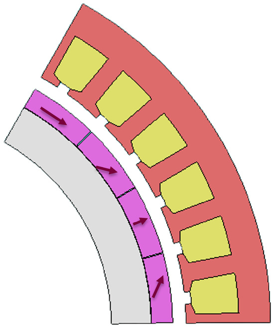
The rated speed of the machine is 20,000 rpm, a design requirement, with a fundamental frequency of 1000 . The power density and efficiency targets of the machine are above 13 kW kg−1 and 96%, respectively, based on the NASA target for aerospace propulsion motors. As the motor is meant for propulsion applications, size and weight matter, and hence, the OD is limited to 300 . Efforts have been made to carefully choose stator and rotor magnetic materials. The magnetic material chosen for the stator is CoFe alloy with 2% Vanadium, VACOFLUX® 48, which features a high saturation flux density of . For the rotor, soft magnetic materials are used for the rotor hub, complemented by permanent magnets. An AISI 4340 annealed steel, recognized for its toughness and strength, is selected to minimize the rotor’s mass. Power-dense NdFeB magnets of grade N48UH with a maximum operating temperature of 180 °C are used as the rotor magnets. These magnets are arranged in a four-segment Halbach array configuration and considered securely glued onto the rotor surface, with retention provided by a carbon fiber framework.
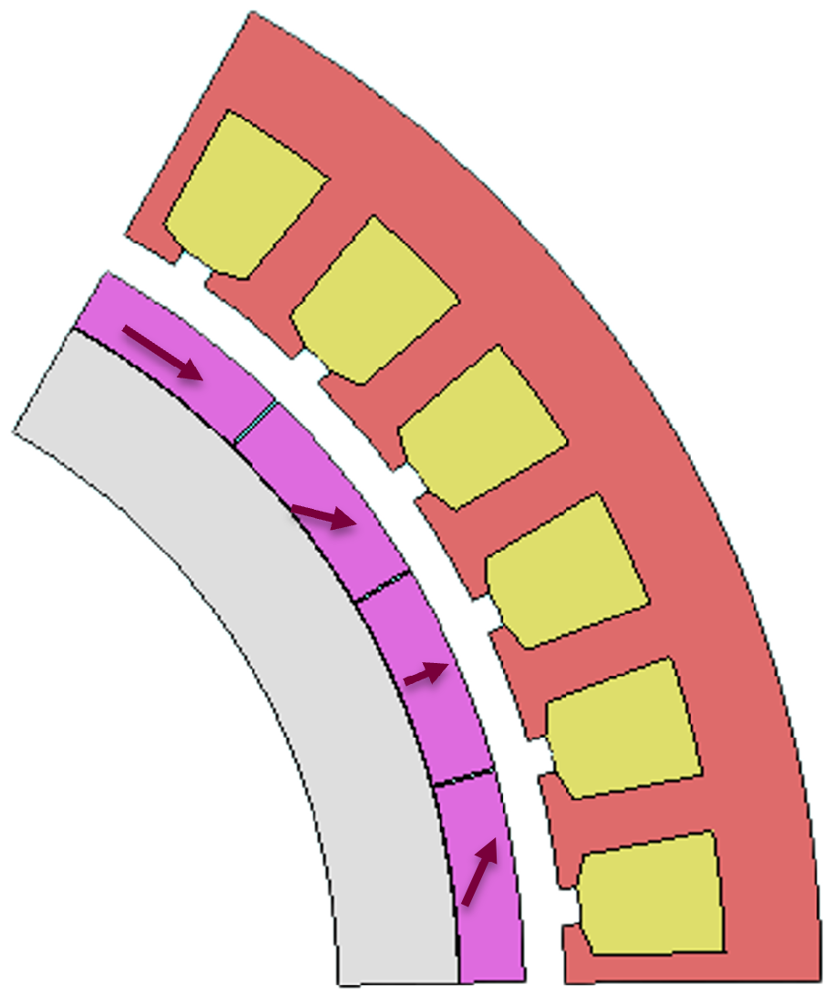
Figure 1 shows the 1/6th 2D-model of the proposed motor developed in JMAG FEM-software (Ver.24.0). Due to symmetry, a 1/6th model suffices for performance analysis, reducing simulation time. The design dimensions and parameters of the baseline motor are shown in Table 4.
Figure 1.
1/6th 2D model of the Baseline motor.
Table 4.
Parameters of Baseline Model.
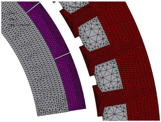
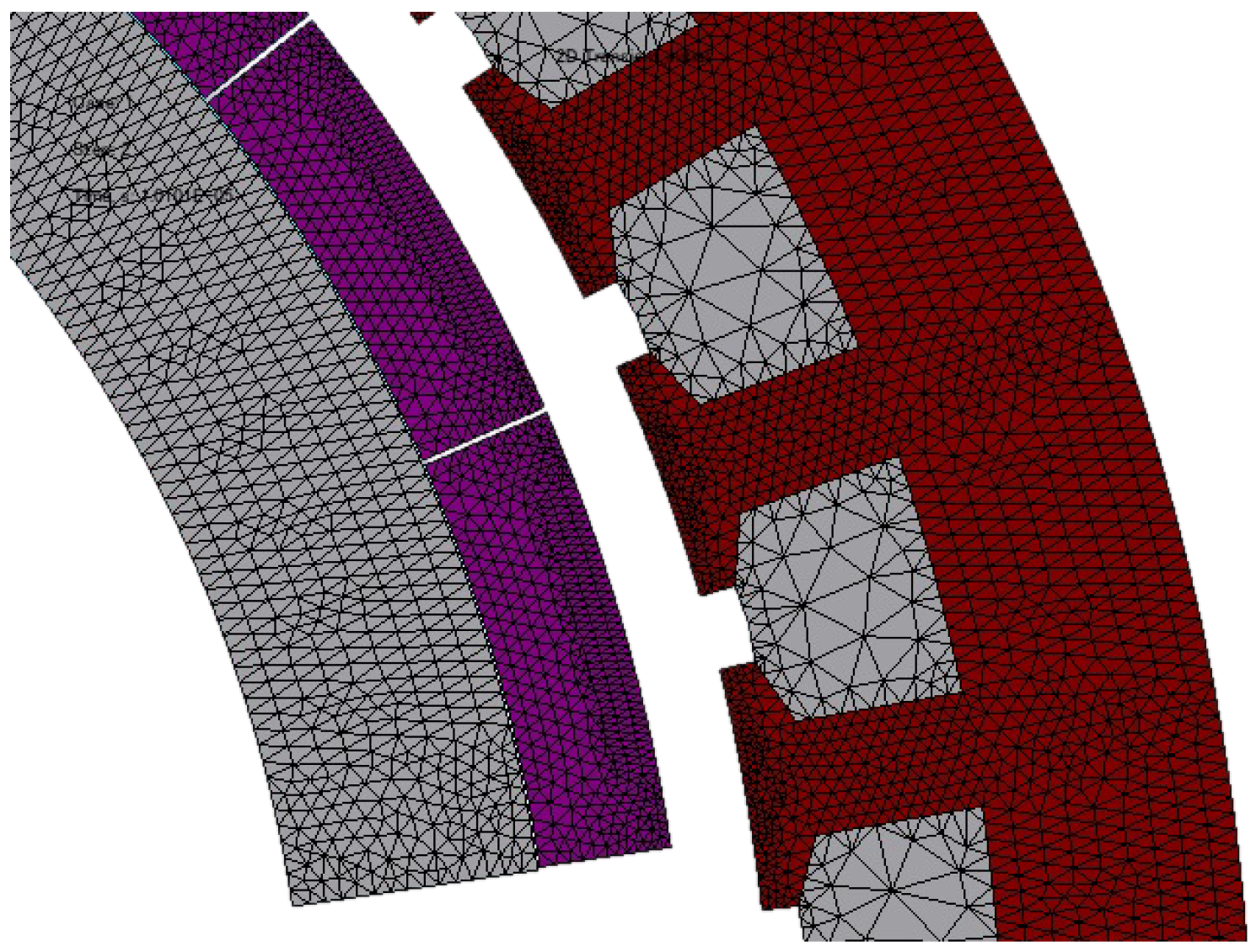
Meshing is very important, and mesh quality significantly impacts the accuracy of FEM simulations. A refined mesh in the airgap is crucial for accurate torque waveform prediction, while coarser meshes (1 ) for the stator, rotor, and windings balance accuracy with computational efficiency. Defining fine mesh on these parts will increase the mesh size and, consequently, the simulation time. Hence, a compromise is made on meshing these parts. Figure 2 illustrates the mesh density for each component used in the simulation.
Figure 2.
2D model with generated fine mesh.
Table 5 summarizes the electromagnetic performance from the transient analysis of the initial design. The required torque for achieving 1 at 20,000 rpm is 477 N·m. The initial design could achieve an average torque of 462 N·m. Among the electromagnetic losses, DC copper loss contributes to a major part followed by the PM-losses. This model is considered as the baseline for further optimization studies and hereafter referred to as the Baseline model.
Table 5.
Electromagnetic performance of the Baseline model.
2.2. Thermal Considerations and Assumption
The electromagnetic design and its optimization of the machine are performed based on the following thermal considerations and assumptions. The normal operating temperature of the magnet is considered as 100 °C, assuming an efficient rotor cooling. The maximum winding temperature of 180 °C is assumed based on the commercially available winding insulation and stator potting material’s maximum temperature limits. The current density of the design is targeted to be less than 26 A mm−2. Maintaining the current density below this limit will allow for increased design flexibility with respect to stator cooling, facilitating predominantly flooded cooling methods. While this approach enhances thermal management, the specifications of the preliminary cooling system design for the stator and its results are discussed in Section 8.
3. Multi Objective Optimization
Motor design is a non-linear optimization problem that usually requires optimizing multiple objectives. The design goal of the proposed machine is to achieve power density and efficiency targets greater than NASA’s 2030 goals on power density and efficiency of 13 kW kg−1 and 96%, respectively. These goals are achieved by a multi-objective optimization, where, the geometric design variables with a significant influence on objectives are varied on a design space. Thus, the optimization process requires repeated iterations of the initial design over a broad design space and is often time-consuming. The FEM model is highly effective in accurately modeling complex nonlinear behaviors, providing a detailed and precise analysis of the motor’s performance.
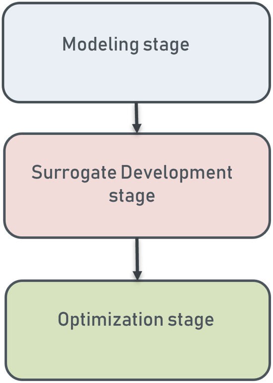
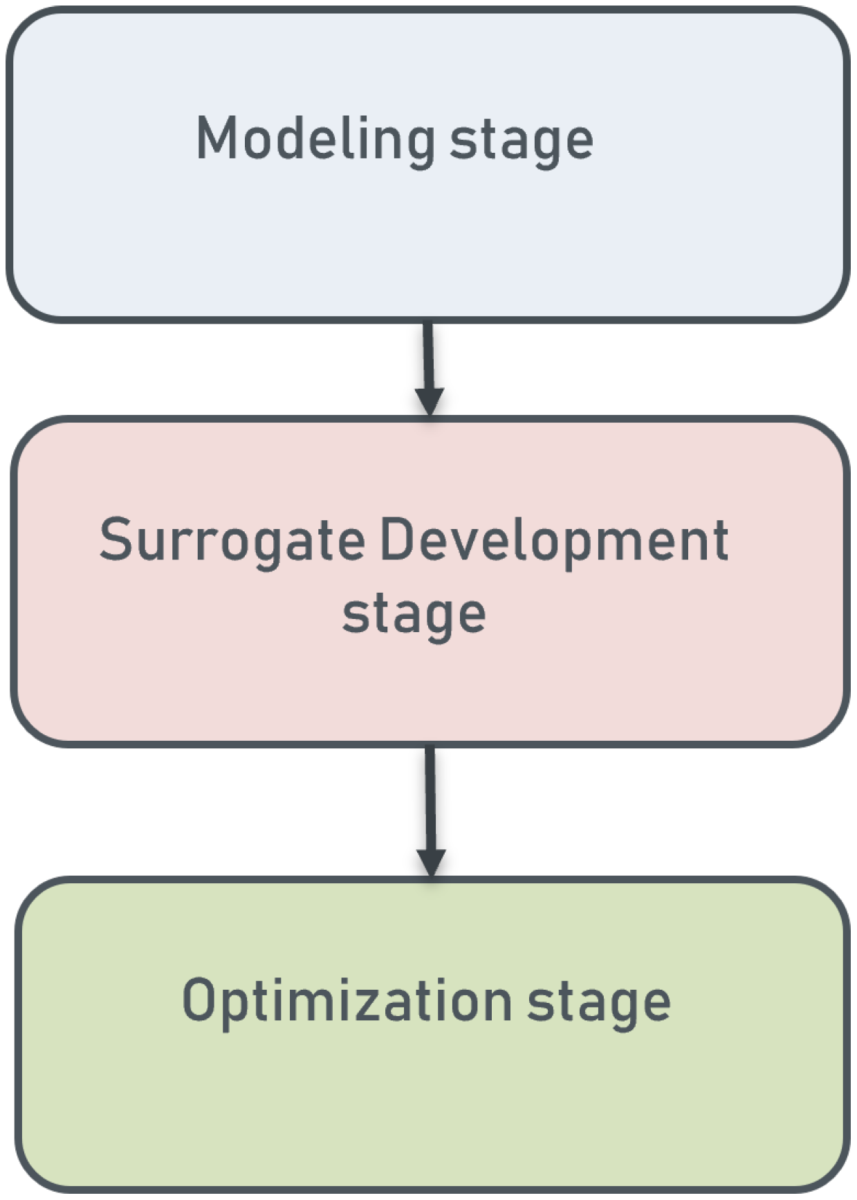
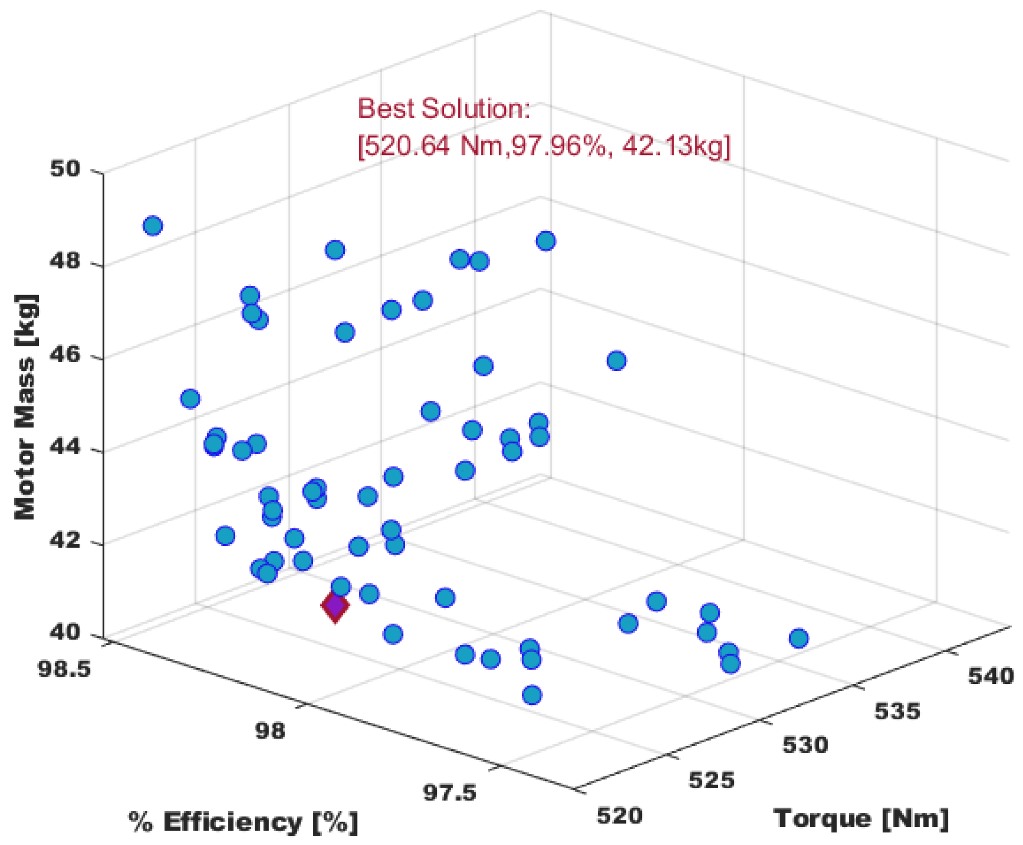
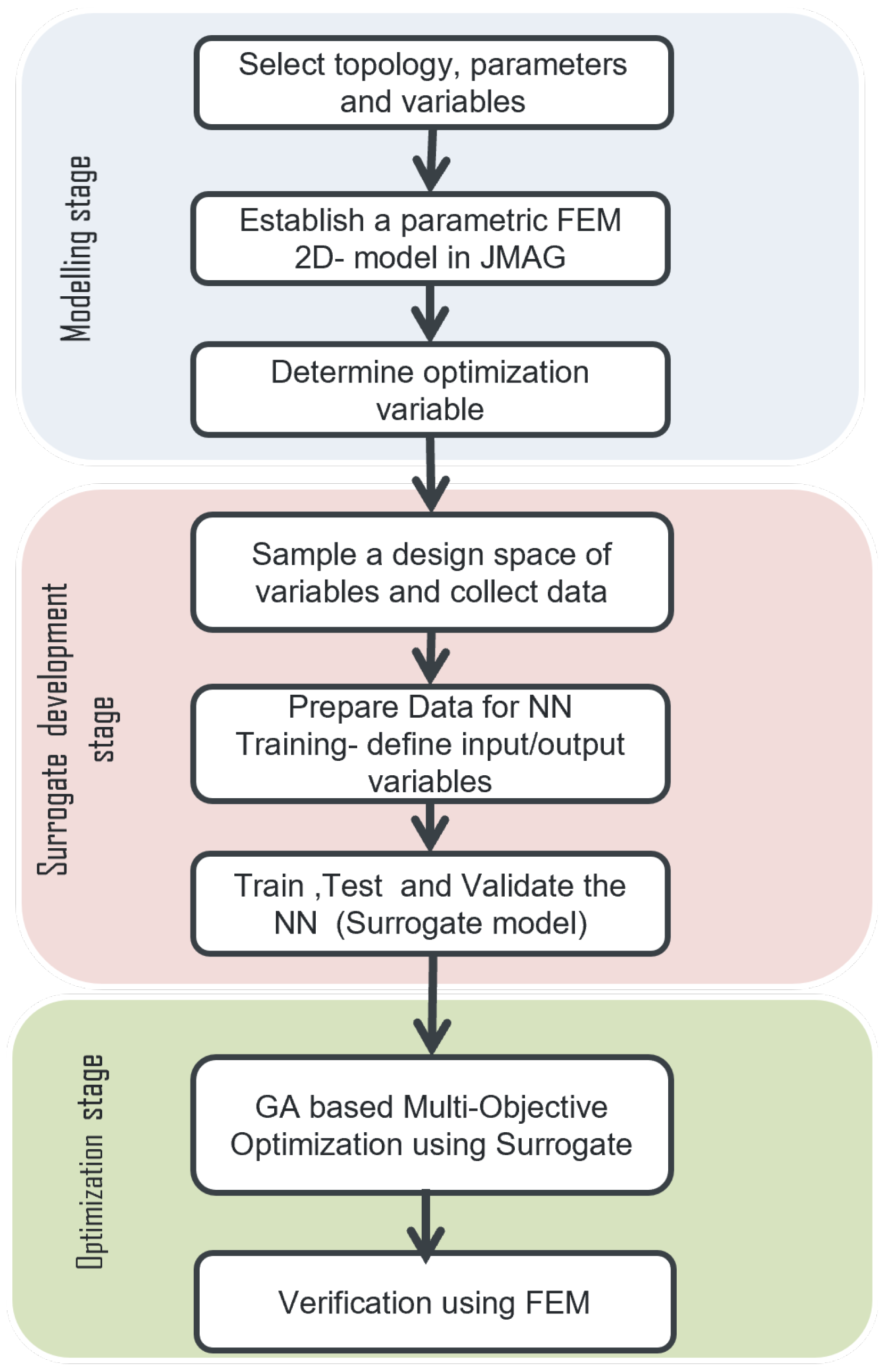
But often, the FEM analysis requires significant computational resources. Researchers have investigated different surrogate modeling techniques to address these challenges. However, conventional surrogate methods often face difficulties in accurately estimating highly nonlinear motor performances. Consequently, there has been increased interest in machine learning (ML)-based surrogate models, which employ advanced algorithms to learn complex patterns from data. The surrogate thus developed offers a more precise performance estimations in motor design. A machine learning (ML)-based surrogate model for a motor design is presented in this paper. Figure 3 shows the optimization framework used for multi-objective optimization of the 1 machine divided into three stages.
Figure 3.
MOO Framework.
3.1. Modeling Stage
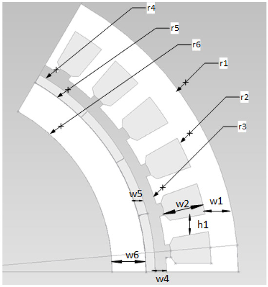
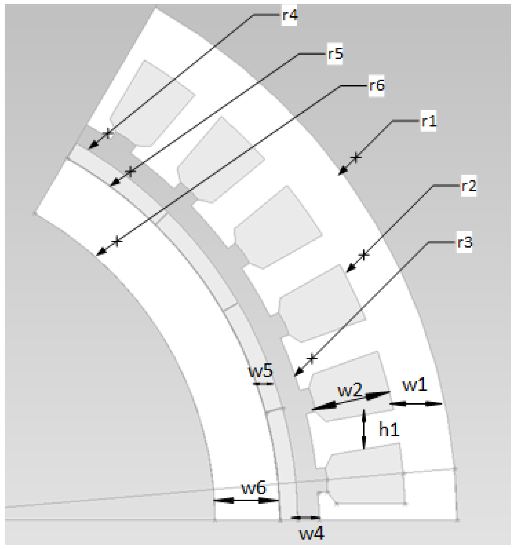
This is the first stage of optimization; in it, the preliminary design of the machine is developed using the critical performance requirements of the motor. Sizing equations, assumptions, and design requirements are considered. The baseline model of the machine is created at this stage, and the model is extended to a parametric model. The parametric model of the proposed MW machine is shown in Figure 4, and the dimensional variables considered are listed in Table 6.
Figure 4.
Parametric 2D model of the machine.
Table 6.
Variables of the Parametric model.
3.2. Surrogate Development Stage
At this stage the parametric model is used to perform simulations to generate the required data for training, testing and validation of a surrogate. This is the most time-consuming stage in optimization. Using the power of ML algorithms, an Artificial-Neural-Network-based surrogate is developed, tested and validated at this stage. This surrogate will replace the time-expensive FE-simulations in the stages of optimization.
3.3. Optimization Stage
This is the final stage of the optimization process; in it, the surrogate developed in the previous stage is used for optimization. This stage involves use of the surrogate model to determine the optimal solution using deterministic or stochastic algorithms. In this work, a stochastic, evolutionary Genetic Algorithm (GA) is used. Once the optimal design has been identified at this stage, analyses are conducted to evaluate the performance of the best design, and finally the prototyping and testing can be done.
The details of the surrogate development and optimization stages are covered in following sections of the paper.
4. Surrogate Development Using Artificial Neural Network
Surrogates are response surface models built analytically using significant motor performance parameters obtained from analytical or FEA models or both [42]. The use of surrogates offers efficient substitutes for time-intensive simulations. Researchers have recently turned to machine learning (ML) algorithms to create surrogate models because of their remarkable accuracy and strong generalization capabilities compared to traditional modeling approaches. Additionally, it is not necessary to define the mathematical relationships between inputs and outputs when utilizing neural network (NN) modeling. To deveop the surrogate, an initial time investment is needed to gather the required data samples for training the network. Once the surrogate is trained, it should be tested and validated. However, once the surrogate is formed, faster design evaluations can be performed over the entire design space.
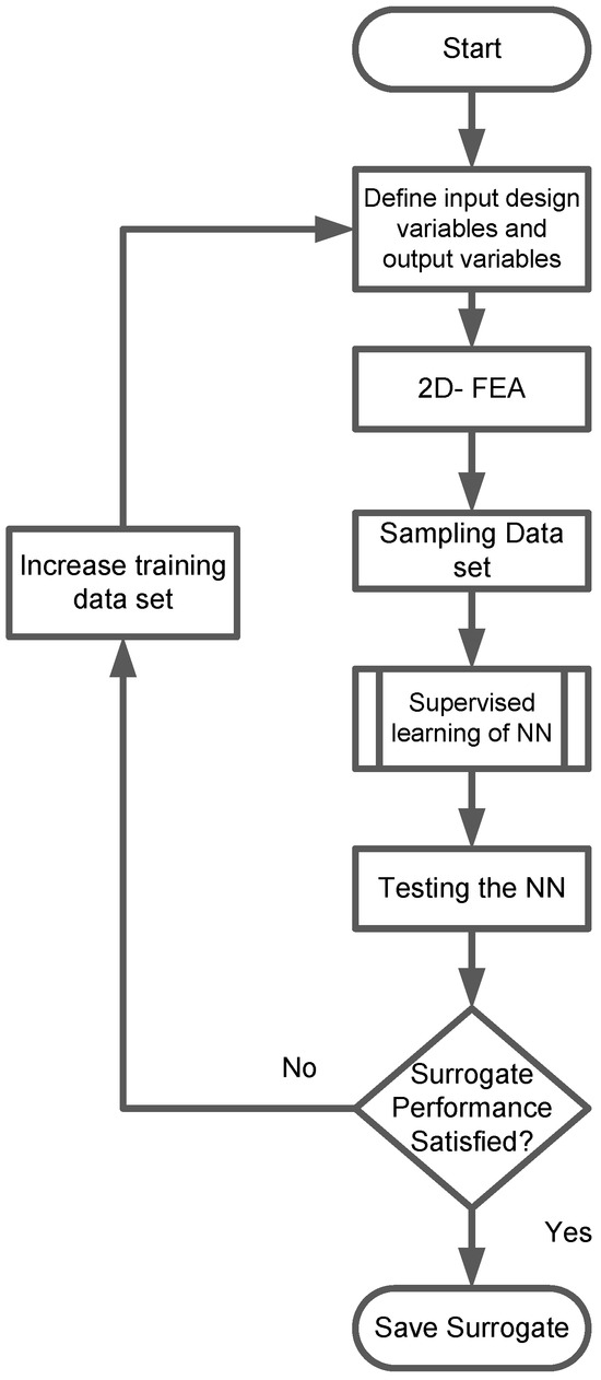
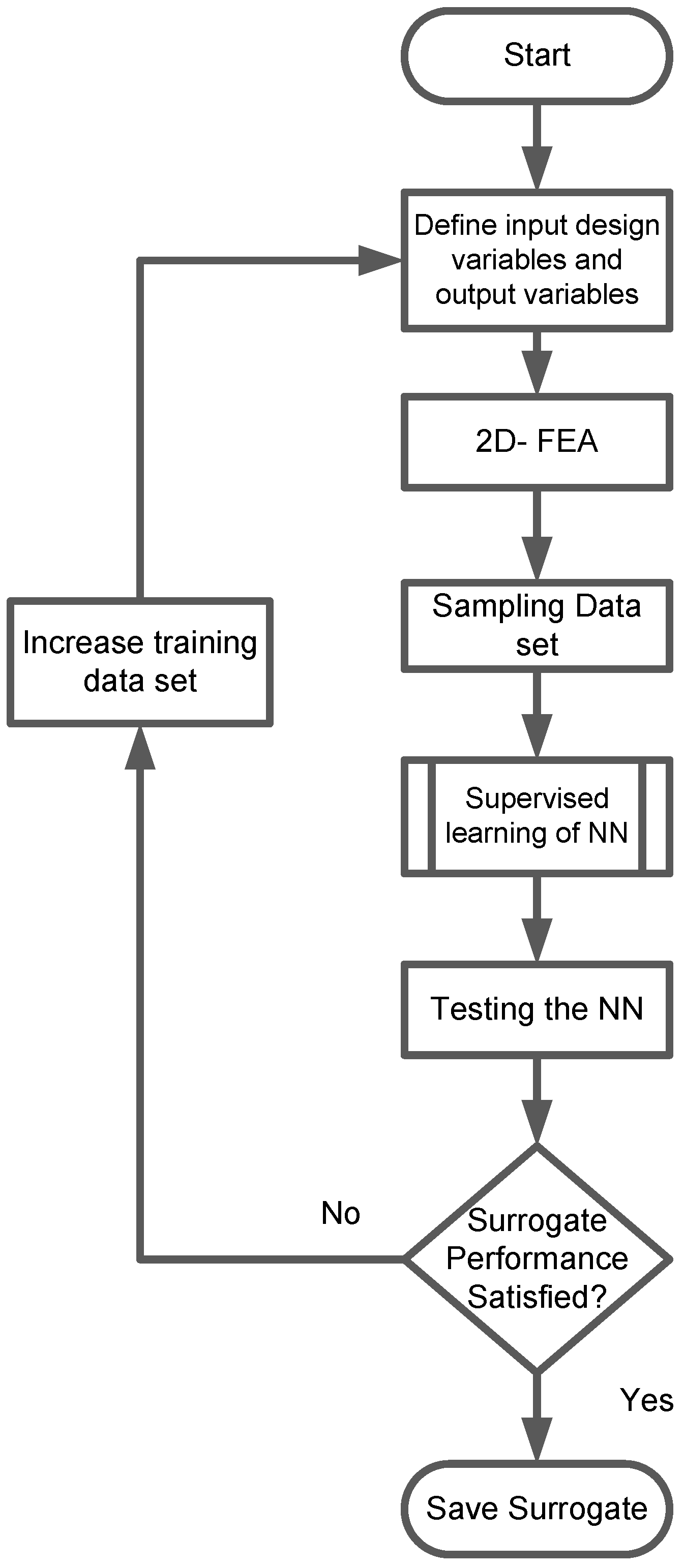
In this work, neural network is used to create the surrogate to predict the performance of the motor for a multivariate, multi-objective optimization process. Figure 5 shows the stages of surrogate development.
Figure 5.
Flow chart depicting stages of surrogate development.
The process starts with defining data collection for network training, testing and validation using the FEM. For this purpose, a sample space of the design variable is created and used to collect the output performance of the machine. Once the sample data is collected, the network is trained using supervised learning. The learned network is then validated using unique data sets that have never been used before in the training phase to check surrogate performance. If the surrogate predictions match the actual FEM simulations, the surrogate is saved. If the performance is unsatisfactory, the training sample increases, and the process repeats. This process is continued till a quality surrogate is obtained. The details of each stages in this process adopted for development of surrogate for the proposed MW machine follows.
4.1. Neural Network
Neural networks are a category of machine learning models influenced by the structure and function of the human brain. These systems consist of interconnected nodes, or neurons, organized into layers that process input data to derive predictions. Multi-layer Perceptrons (MLPs) are used for deep learning processes and are called machine learning.
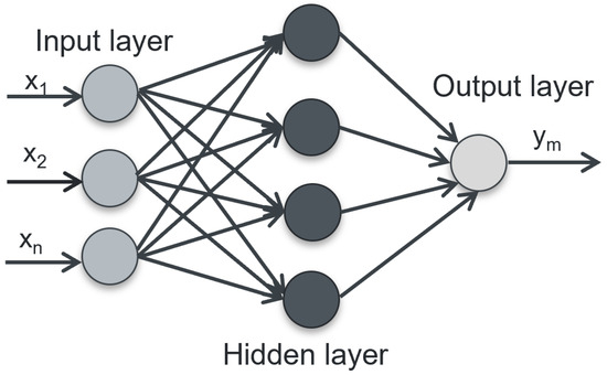
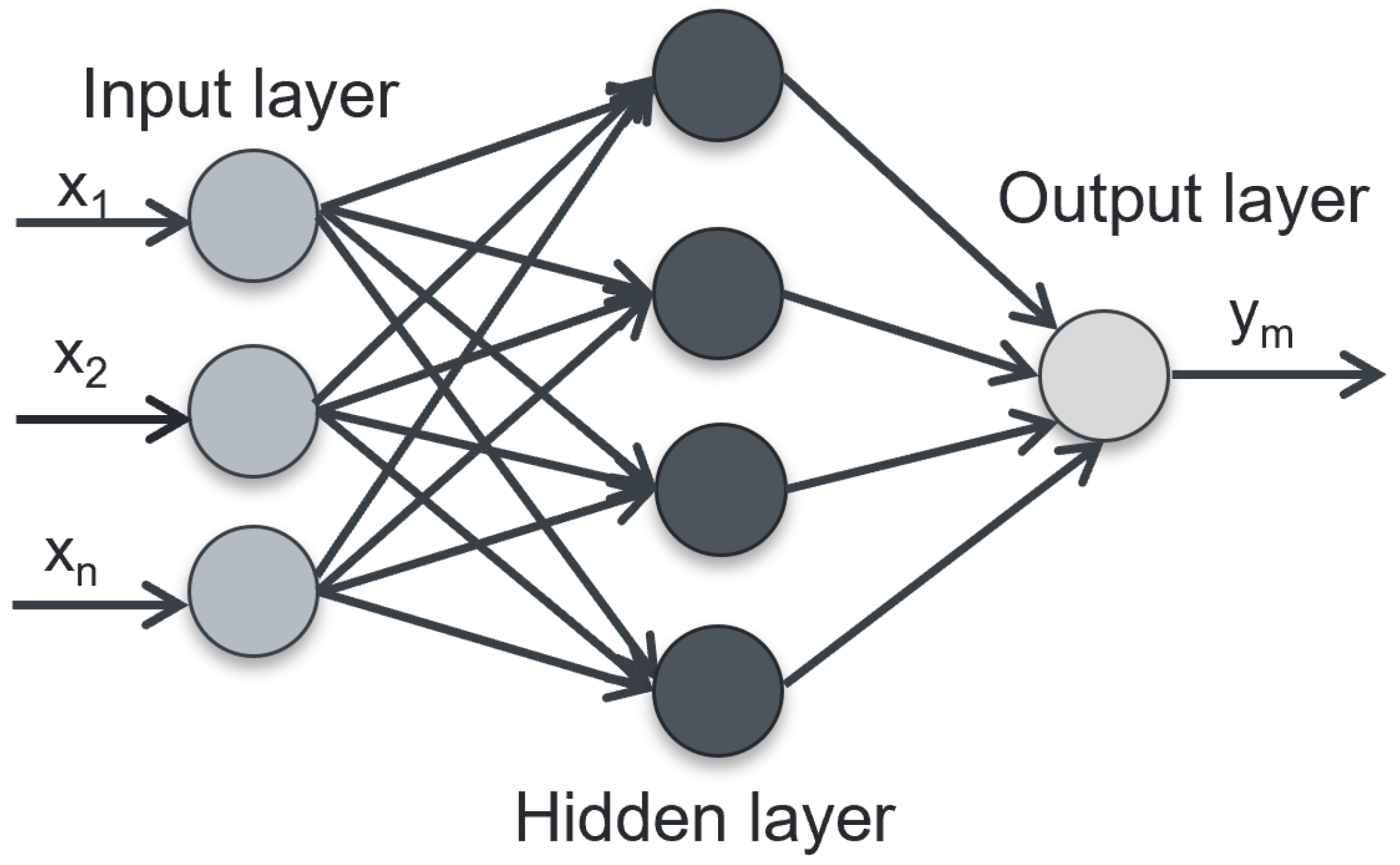
In the context of motor design, neural networks can assist in optimizing various parameters by learning from performance data and design specifications. A typical MLP’s structure consists of input layers, multiple hidden layers, and an output layer, as shown in Figure 6. The number of input features determines the neurons in the input layers, whereas that in the output layer is equal to the number of outputs predicted by the MLP model. Some of the input variables in the design will be interdependent, and a proper decision should be made to choose the variable. The system becomes complex as the number of input and output variables increases. The number of hidden layers, the neurons in each layer, and the activation function are selected using the heuristic approach in this work.
Figure 6.
Multilayer perceptron (MLP) with n inputs and m outputs.
A supervised learning network based on a backpropagation learning algorithm is selected in this work. The Levenberg Marquardt (LM) algorithm trains the backpropagation neural network (BPNN), ensuring the local minimum convergence.
4.2. Variables and Data Collection
Among the various design variables listed in Table 6, six variables that have a significant influence on the torque, efficiency and motor mass are selected as input variables for the neural network surrogate. Refs. [47,48,49] present the sensitivity analysis of geometric variables on the performance of the PM machines. Table 7 represents the input variables and their upper and lower bounds. The stator back iron thickness () is varied from 13 to 19 . A minimum of 13 thickness ensures saturation on the back iron within the allowed range. The slot area depends on the pole arc and slot height (). They are varied from 8 to 15 and to , respectively, to explore the best design with current density within 26 A/mm2. The magnet thickness varies from 6 to 12 based on the possible minimum and maximum thickness the supplier can manufacture. The teeth thickness’s lower and upper bounds are 6 and 9 , respectively. A minimum airgap of is considered to accommodate the carbon fiber and stator sleeve for the cooling. It can be varied up to , with a mechanical airgap of with the rest being assigned to the carbon fiber and stator sleeves.
Table 7.
Design Variables selected with their range.
Each input variable varies within its lower and upper bound in a fixed step determined by its significance on the objective, such as torque, efficiency, and mass (Table 7). Considering these variations, the total combinations of input data is about 26,880, which is a larger number of data sets. Each 2D -FEM takes about 60 s to run and 20 s to save and post-process data. It will take around a month of simulation to collect the data in this entire design space. Hence, selecting the whole range of data is not a viable solution. A well-selected sample space of the input variable is enough to capture the features in this entire range. For this purpose, down-sampled data, which capture the entire range of parametric variation, are used to train and test the NN. A stratified random sampling technique, where data points are sorted and divided into segments for uniform selection across different input variables to ensure diverse representation, is used.
After conducting several iterations on a heuristic basis, it is found that a data sample set of 850 is enough to represent the entire design space. The number of nodes in the output layers is determined based on the number of performance parameters the network should predict for optimization. Six significant performance parameters are identified as the desired output and are listed in Table 8. The average torque, motor mass and efficiency predicted by the network are used for optimization. The rms-phase voltage and current density are considered as constraints for optimization.
Table 8.
Output Variables.
Simulating 850 data points took 16 h and 42 min on a personal computer with intel i7 core and 64 GB RAM. Once the input and output variables for the design space are collected, the next phase is to develop the neural network surrogate and train it.
4.3. Training, Testing and Validation
The geometric design optimization of the 1 machine is performed using a cascaded LM-BPNN network. The neural network is composed of input and output layers with six nodes each, and four hidden layers, with the configuration containing 12 neurons determined through a heuristic approach. This setup is chosen to balance training accuracy and model complexity. While increasing the number of layers or neurons might improve training accuracy, it also raises the likelihood of overfitting, which occurs when the model becomes more complex and fails to generalize effectively to new data.
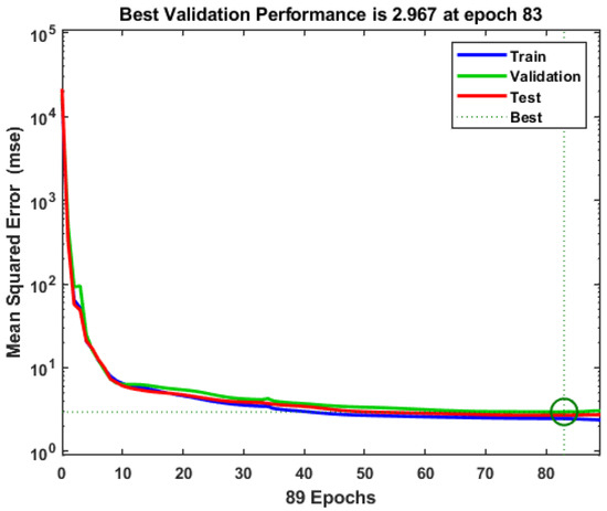
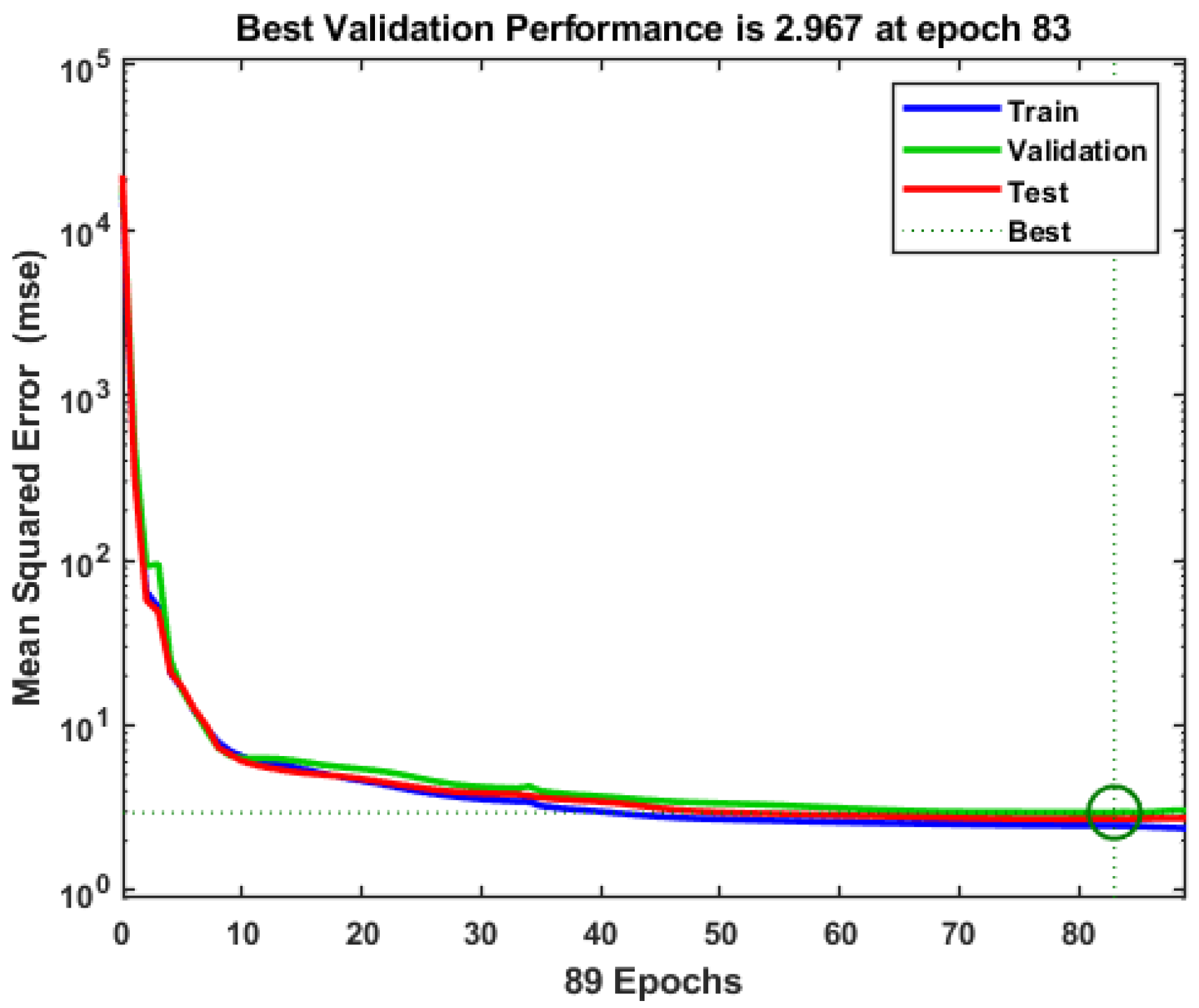
The network was trained using 850 samples of input–output data collected through FEM simulation. The results of the training and validation process are illustrated in Figure 7. The dataset was divided randomly such that 70% of the points were allocated for training, 15% for validation, and the remaining 15% for testing the network. The Levenberg–Marquardt algorithm effectively trained the network over 89 epochs. To evaluate the network’s performance, the mean square error (MSE) was utilized as the loss function. Since the inputs and outputs were not normalized, the error convergence was within the hundreds. Furthermore, the linear regression correlation coefficient (R) served as an additional metric for assessing the accuracy and precision of the test set fitting.
Figure 7.
The training, validation and testing profiles of NN.
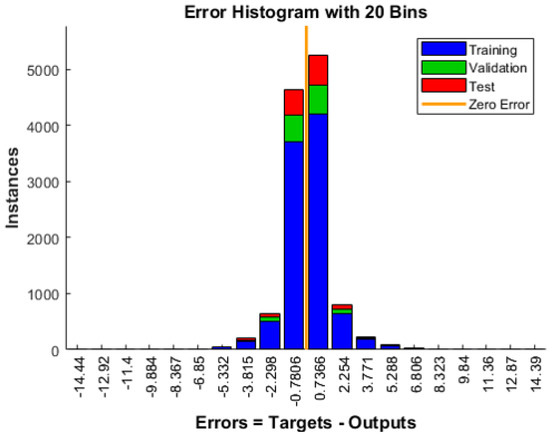
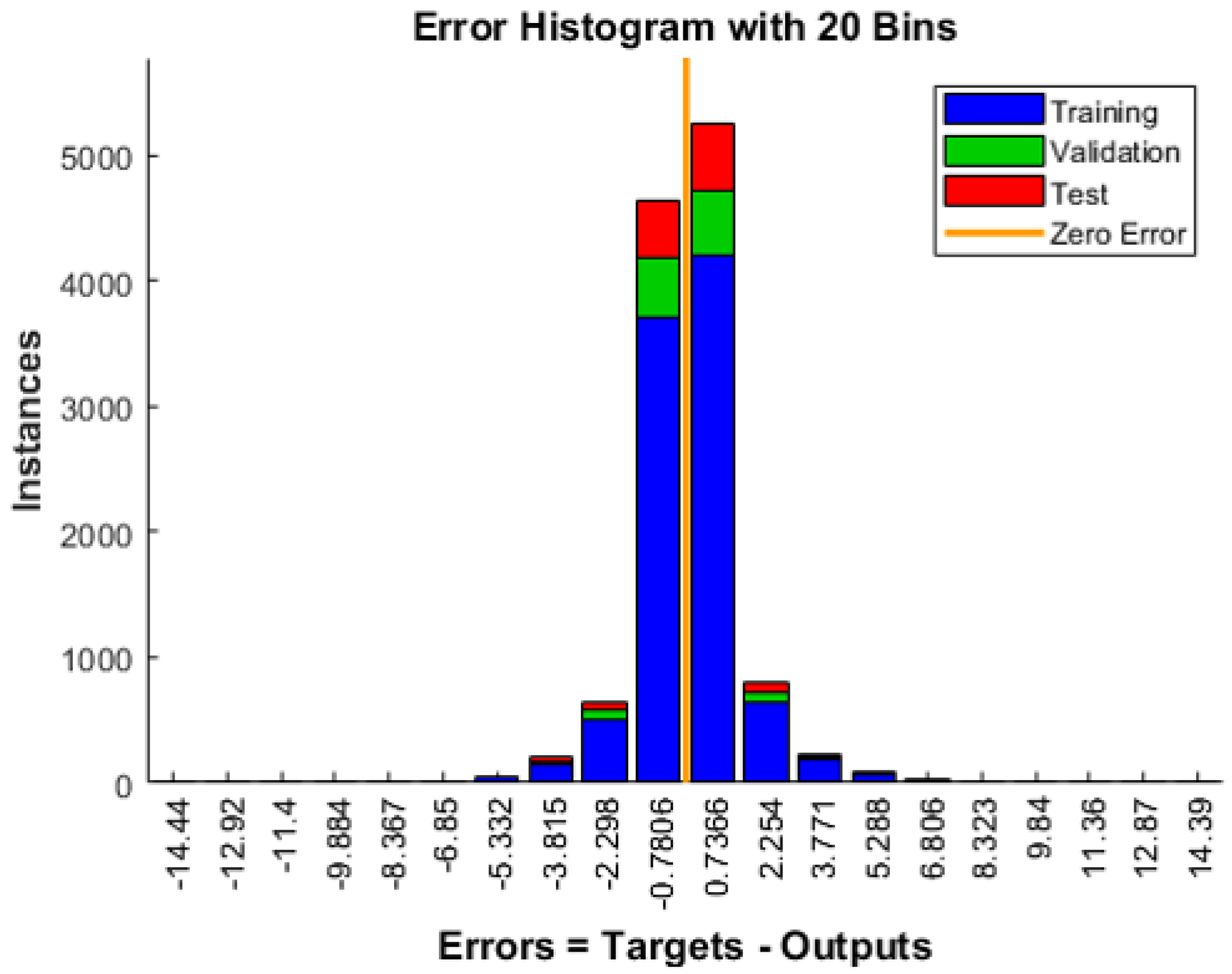
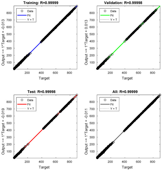
Figure 7 illustrates the error convergence curve for training, validation, and testing as a function of the number of epochs. The error histogram is illustrated in Figure 8. The MSE for the training set is 2.96, while the regression coefficient R is 0.9999 (Figure 9).
Figure 8.
Error histogram of the train, validation and testing of NN.
Figure 9.
NN Regression value for training, testing and validation.
Given that the MSE is quite low and R is nearly equal to 1, the backpropagation neural network (BPNN) demonstrates a high level of accuracy in capturing nonlinear characteristics.
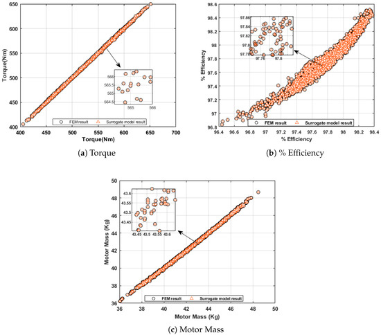
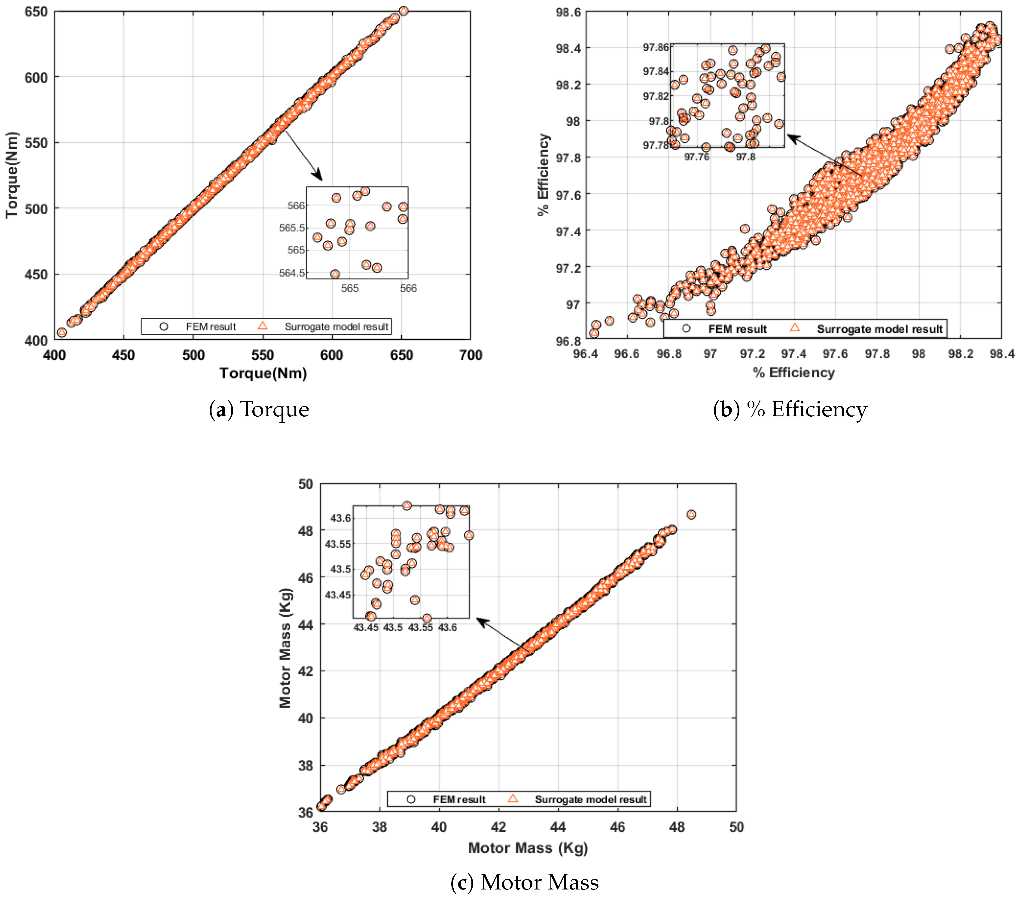
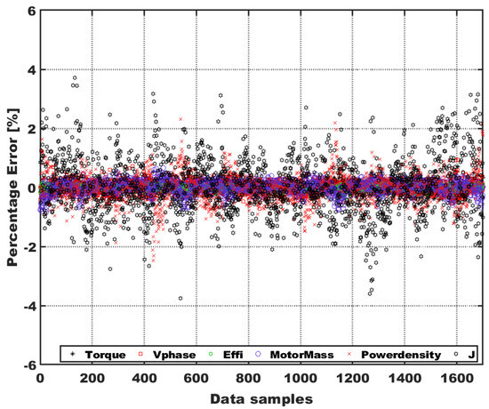
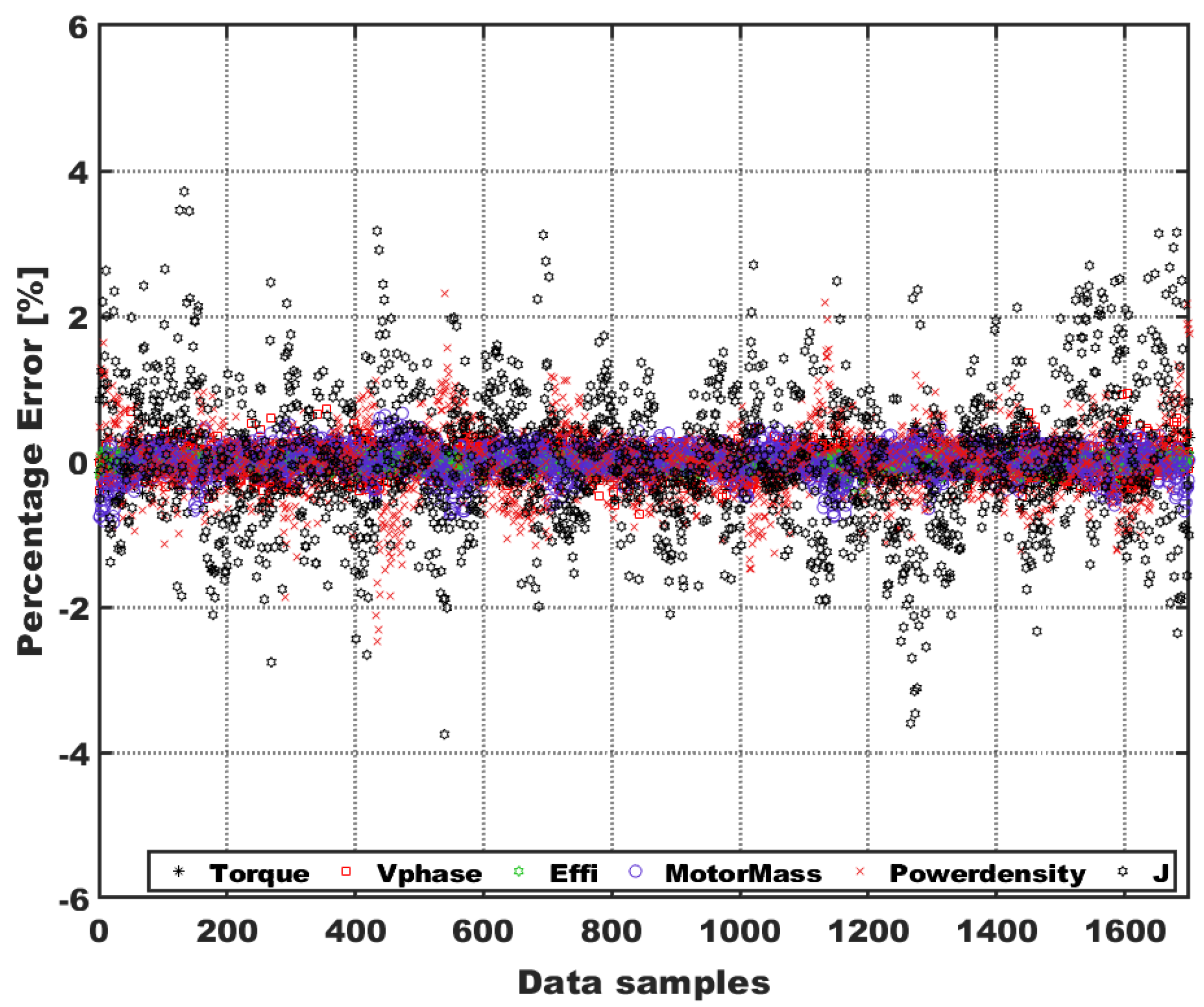
After effectively training the network, its generalization ability was assessed using 1700 data points that were not included in the training or testing stages. A large sample of data was selected to confirm the prediction quality of the surrogate. These data span the entire design space and have not previously been used in the training stages. The outputs predicted by the BPNN were then compared to the actual values obtained from FEM simulations. Figure 10 shows the comparison for torque, percentage efficiency and motor mass. The percentage error for key parameters—torque, voltage, mass, efficiency, power density, and current density—is shown in Figure 11. None of the predictions for these 1700 points exceeded a 5% error, with most predictions remaining highly accurate and exhibiting minimal discrepancy.
Figure 10.
Verification between the surrogate model predictions and FEM simulations results. (a) Torque (top-left), (b) % Efficiency (top-right), and (c) Motor mass (bottom-center).
Figure 11.
% error plot of the six output variables of surrogate model to actual 2D-FEM simulation results.
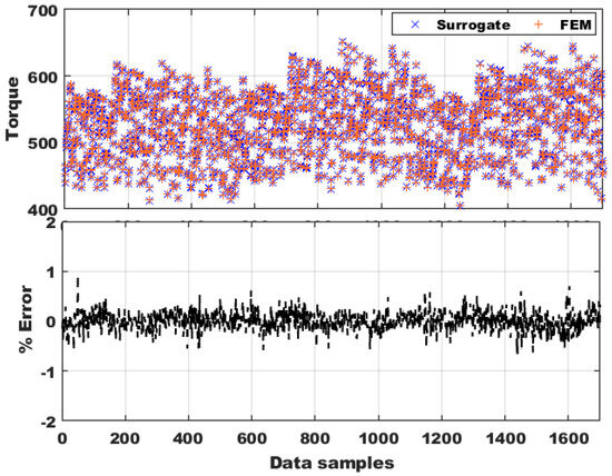
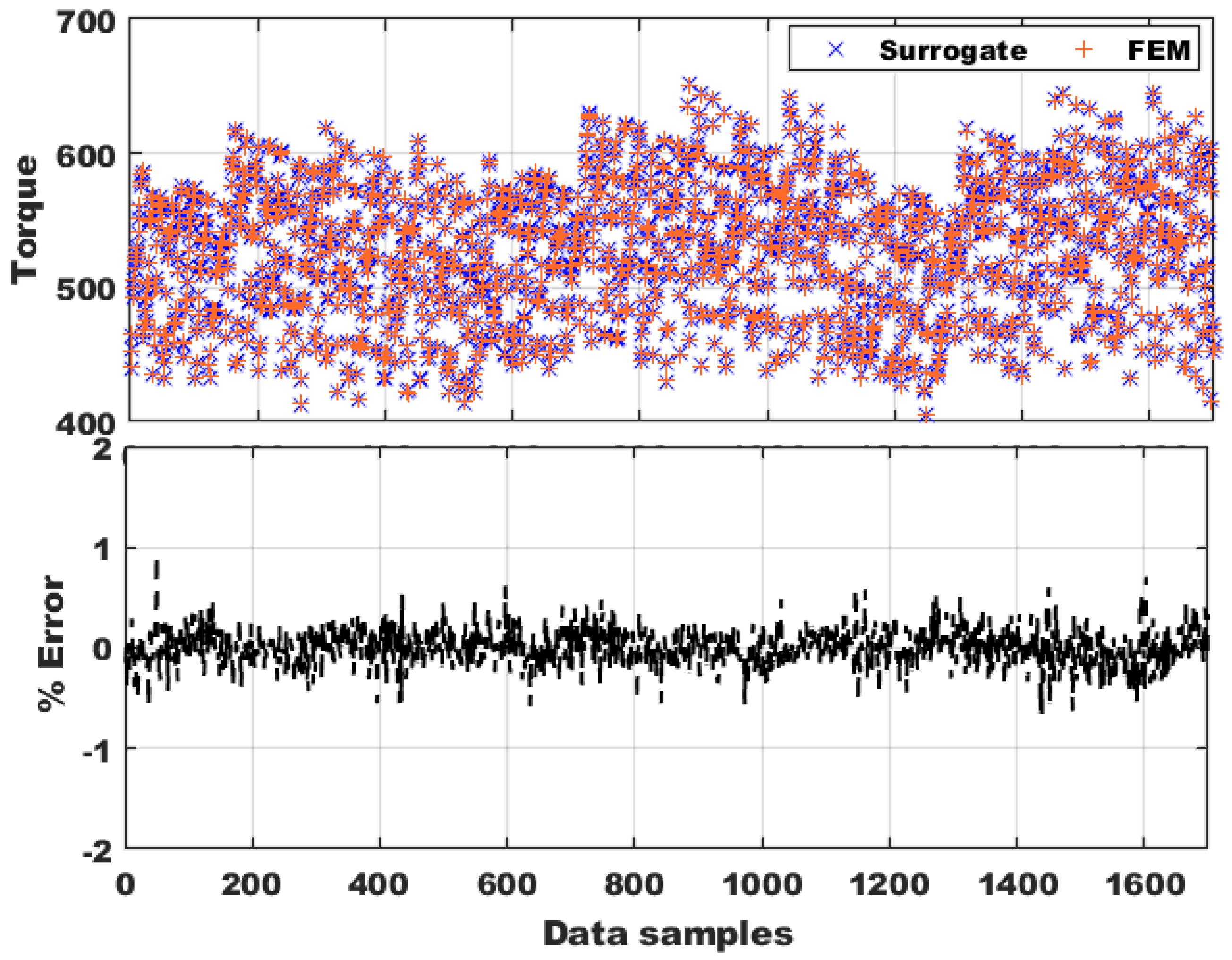
Figure 12 shows the FEM torque and surrogate predicted torque for the validation points, along with the corresponding percentage error plot. Torque predictions have very minimal error, not exceeding 1%. This demonstrates that the neural network has been effectively trained. Consequently, the surrogate model can reliably replace FEM simulations, providing rapid predictions of output parameters in just a fraction of a second. This capability has the potential to significantly reduce the time required for iterative design processes in optimization.
Figure 12.
Surrogate predicted torque and FEM torque with their % error.
5. Hybridized Algorithm with GA and ANN
As the surrogate model is very promising, the next step is to utilize it for identifying the optimal design within a vast design space. Since the neural network (NN) alone cannot achieve this optimization, an evolutionary algorithm, such as the Genetic Algorithm (GA), becomes essential. This section will detail the multi-objective optimization process, highlighting the integration of the surrogate model and GA in pursuing optimal design solutions.
5.1. Genetic Algorithm
Genetic Algorithms (GAs) are inspired by the principles of biological evolution and integrate concepts such as competition, hybridization, selection, mutation, and reproduction, forming the foundation of the algorithm [50,51]. The essence of a Genetic Algorithm lies in its mimicry of evolutionary processes, whereby organisms advance from simpler forms to more complex ones over time, drawing on ideas like natural selection and “survival of the fittest” [52].
The Genetic Algorithm used for the optimization in this work is the NSGA-II algorithm. The GA and NN are hybridized, to make faster optimization. The input for optimization (chromosomes), which is the the design variables listed in Table 7, is fed to the surrogate to predict the objective of the multi objective optimization problem: maximizing torque and efficiency, and minimizing motor mass. The details of problem statement formulation is described in the next section.
5.2. Problem Statement
The MOO problem can be expressed as follows.
Minimize
subject to the constraints
The multiple objectives include, torque, efficiency and motor mass. The negative sign for and denotes that the function values are maximized. The electromagnetic torque should be maximized to obtain higher output power. The minimum required torque for the proposed 1 machine is 477 N·m at the rated speed. The design optimization is performed for the rated power. Hence, for the optimization process, the torque reference () is set to 520 N·m, which is approximately 10% higher than the required torque. This adjustment serves to compensate for any potential torque drop that may arise due to unforeseen non-idealities in the system at the later stages of design.
To achieve specific power more than 13 kW kg−1, the mass of the motor should be minimized. The mass considered in the optimization is the electromagnetic mass and does not include the housing or any cooling system. Copper weight, magnet weight and iron weights are accurately estimated using the geometry, and their material densities. The targeted efficiency of the motor is greater than 96%, and therefore, the efficiency () is maximized. The upper and lower boundaries of the design variables are listed in Table 7.
The constraints for optimization are selected based on the design goals. Two non-equality constraints: phase rms voltage and current density are considered. The phase rms voltage should be less than 730 (), which is decided based on the DC link voltage. The current density of the design is set to be lower than 26 A mm−2. Maintaining the current density below this limit will allow for increased design flexibility with respect to stator cooling.
5.3. Optimization Using GA
The MOO using Genetic Algorithm is performed in MATLAB R2025b using the optimization toolbox. The gamultiobj function is used for optimization. There are three objectives, torque, efficiency and mass, and three constraints (3)–(5), as explained in the problem statement. The initial set of variables is randomly chosen and defined in optimization. A population size of 100 is chosen heuristically. Increasing the population size will help to explore more designs, at the cost of more iterations. As a tradeoff between number of iterations and optimization, the time it is randomly selected. The recommended size of maximum generation depends on input variables and is given by 200 times the number of variables which is 1200 in this case, but a close value of 1000 is selected. The crossover fraction and mutation fractions are 0.8 and 0.1, respectively. The tolerances for constraint and function are set to 1 × 10⁻² and 1 × 10⁻³, respectively.
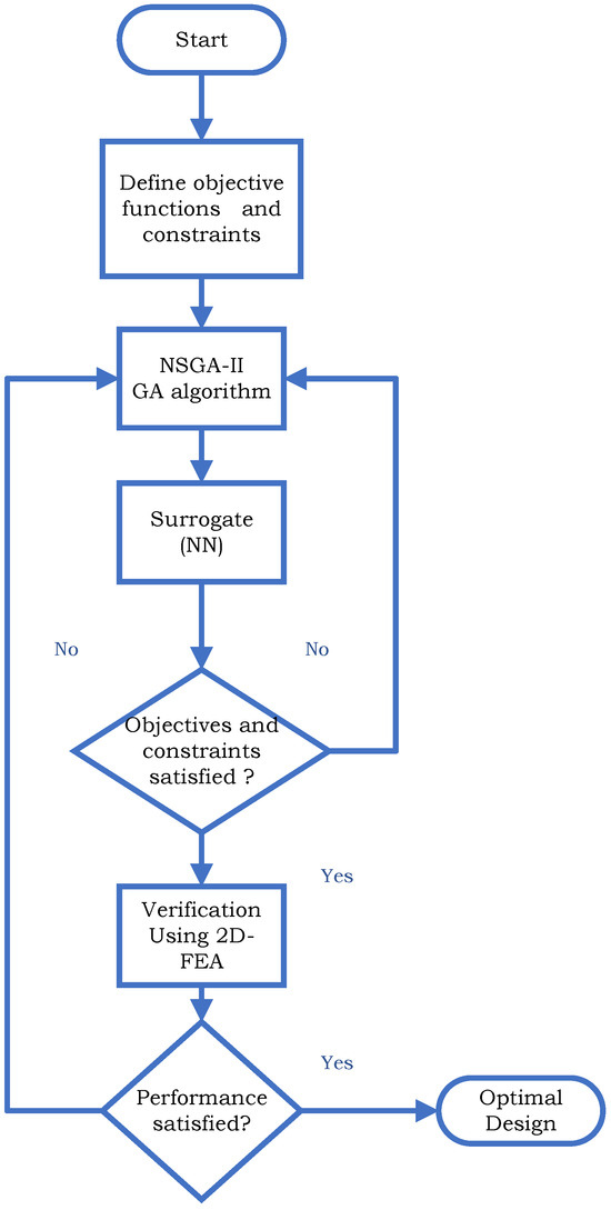
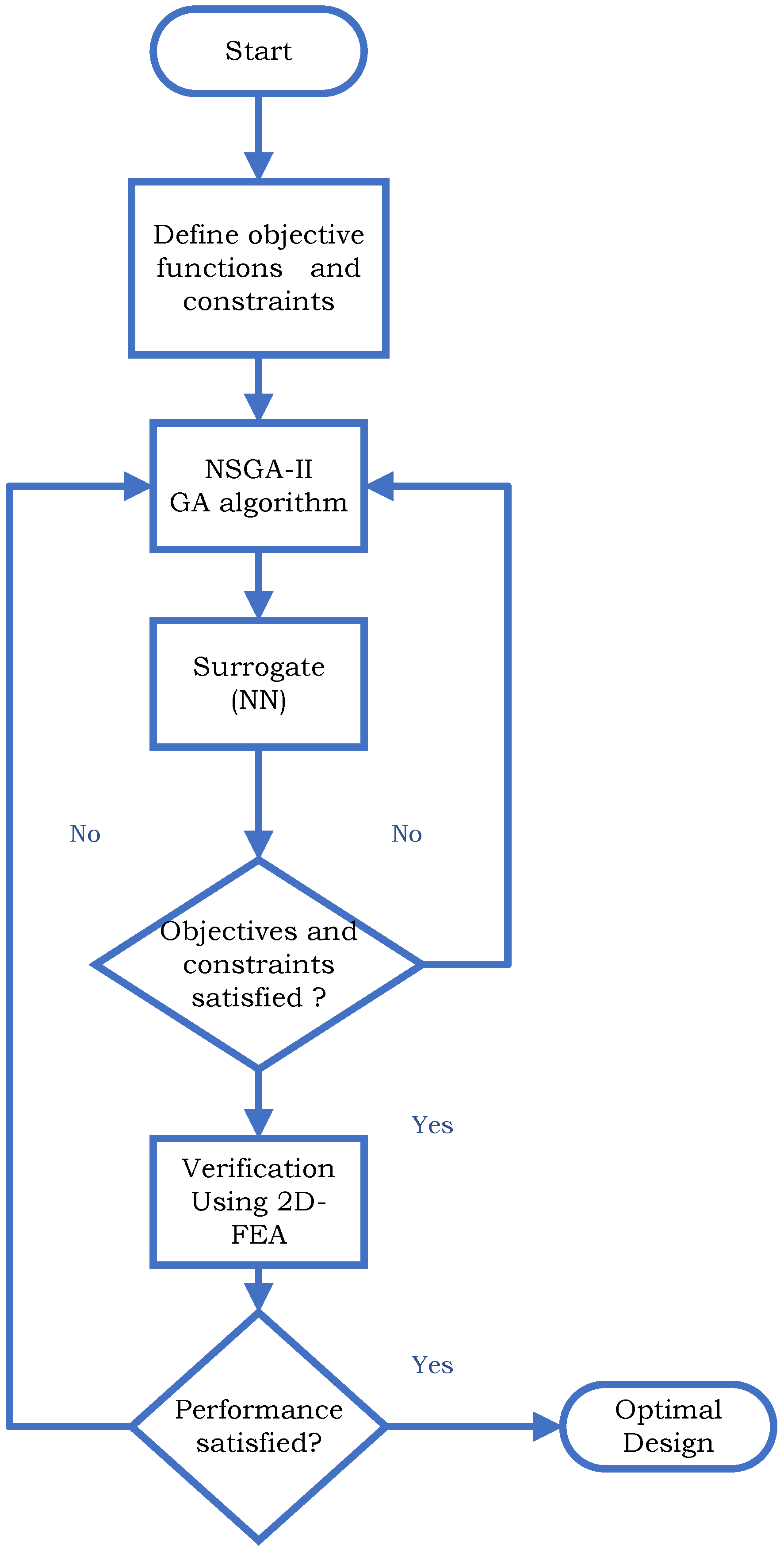
A flow chart of optimization process is illustrated in Figure 13, starting with a random initial population followed by the stages of the Genetic Algorithm. The surrogate developed in Section 4 is integrated into the optimization. For each chromosome set, the surrogate predicts the six output variables such as torque, efficiency, motor mass, etc. Thus, the use of FEM is replaced, which makes the iterations faster. Chromosomes progress through each generation through a series of successive iterations.
Figure 13.
Flow chart of hybridized optimization.
All solutions for chromosomes that satisfy the objectives and constraints are presented as a Pareto plot at the end of the optimization process. The optimization stops when the relative change in the volume of the Pareto set is less than the tolerance set and constraints are satisfied to within their tolerance range. The best solution is selected from the Pareto and is verified using the FEM simulation. If the error is not acceptable, the optimization process is reiterated with changes to algorithm parameters such as population size, generation, etc., to explore a wider design space. If the error between the FEM results and predictions of the best solution is acceptable, the design is considered an optimal solution and is considered for further electromagnetic study and analysis.
Optimization is performed in a computer with Intel processor Core(TM) i7-9700 CPU with processor speed of 3.00 GHz and a RAM of 64 GB. With the optimization settings known, the GA optimization using the neural network surrogate completed the optimization in 102 generations with in 20 min. The gamultiobj stopped because the average change in the spread of Pareto solutions is less than function tolerance.
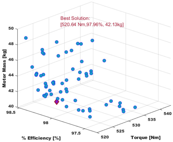
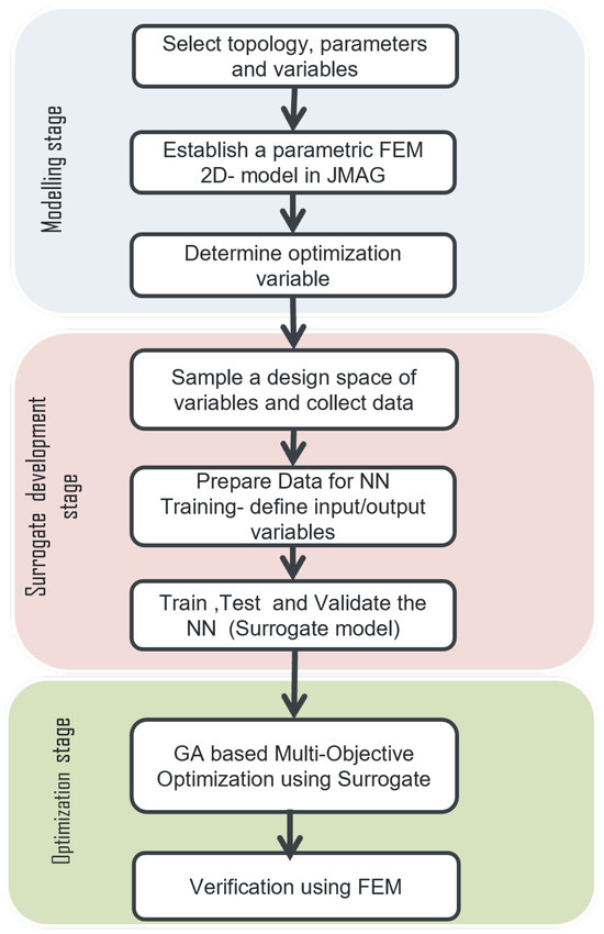
The algorithm called the surrogate 17,251 times during the optimization stages. If the FEM software had been used instead of the surrogate, it would have taken days of simulation to reach the optimal solution. The Pareto front of the solutions satisfying the objectives and constraints is shown in Figure 14. The x-axis denotes torque, whereas the % efficiency and motor mass are represented on y- and z-axes respectively. All the solutions ensures a minimum torque of 520 N·m and an efficiency greater than 97.5%. Of the many solutions, the one with a torque of 520 N·m, efficiency of 97.96% and mass of is selected for further study and hereafter called as the optimal solution (Design A).
Figure 14.
Optimization Pareto with the selected design marked in red.
Although there are several points with higher efficiencies, than Design A, they are associated with high motor mass, which is an undesirable characteristic. The selected solution ensures maximum torque and efficiency with a minimum motor mass.
Table 9 shows the predicted electromagnetic performance by surrogate and actual 2D- FEM results with the % error between them. The predicted values are very close to the actual results from 2D-FEM simulations. The error is less than in most cases except the current density, which is about but still under the ±5% tolerance band.
Table 9.
Design A: Performance comparison with surrogate prediction and FEM simulation.
Figure 15 shows the complete optimization process, hybridizing the NN-based surrogate and the NSGA-II algorithm. The proposed algorithm for machine design is promising, and an optimal solution is reached very fast.
Figure 15.
Proposed MW motor MOO design process stages: detailed representation.
6. Performance Evaluation
Electromagnetic Performance
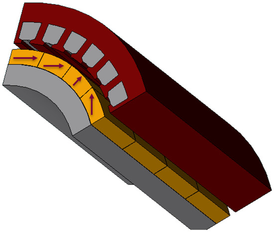
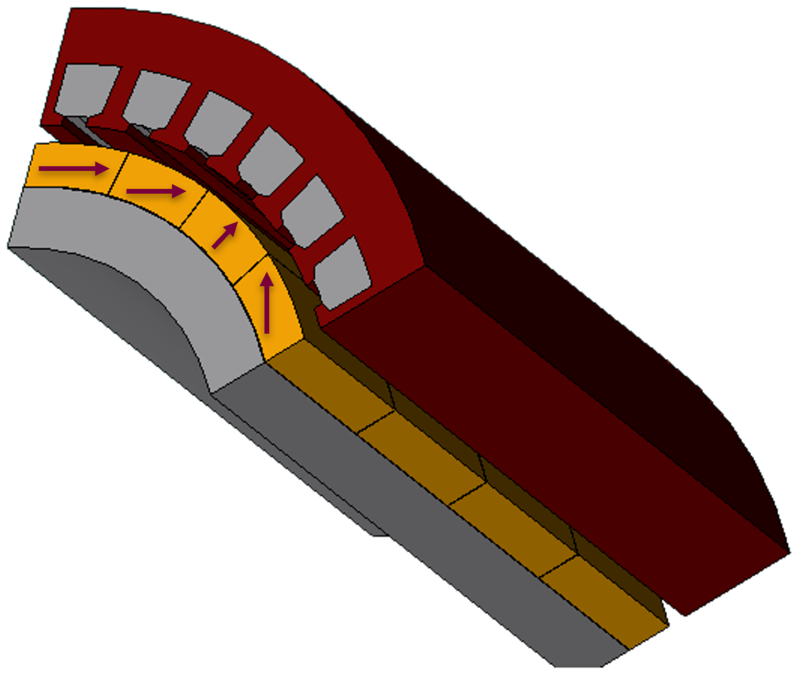
The optimal solution (Design A) is further studied to evaluate the electromagnetic performance. To assess the effectiveness of the optimization process, a comparison is conducted between the baseline model and Design A. Figure 16 shows the 3D-FEM optimized model (1/6th) of the proposed machine.
Figure 16.
3D FEM 1/6th model of proposed MW motor.
Table 10 compares the design variable values between the two. The stator back iron increased from 12 to 14 , while the slot height decreased from to 12 . The magnet thickness increased by 1 . The optimal airgap is found to be .
Table 10.
Comparison of design variables before and after optimization: Baseline vs. Design A.
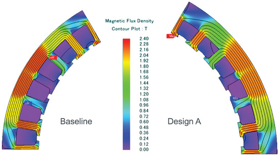
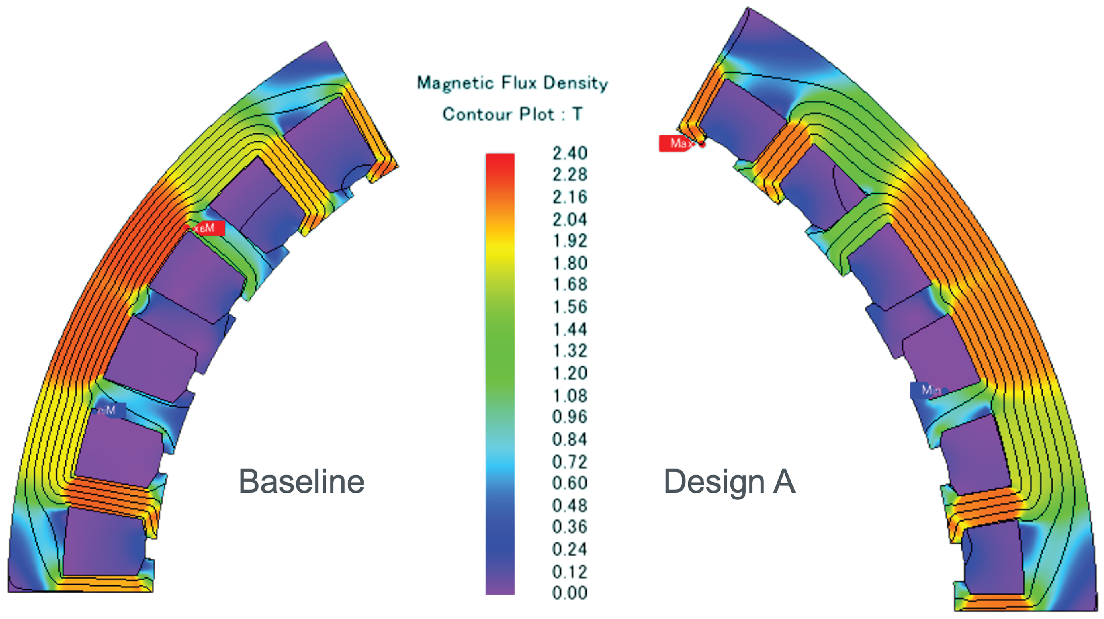
The comparison of electromagnetic performance between baseline model and Design A along with the percentage improvement is presented in Table 11. Design A achieved a 10% reduction in rated current compared to the baseline model. This reduction in current is due to the improvement in flux densities in the stator steel. Figure 17 compares the stator iron flux density, demonstrating improved saturation levels in the core and teeth. While Design A’s overall weight is 2.64% higher than the baseline, the electromagnetic performance is improved significantly. There is a 19% reduction in DC copper loss and a 12% reduction in total electromagnetic losses. Although the 0.38% improvement in efficiency sounds small, at this megawatt power level it is significant. The efficiency reported in Section 5 for the Optimal design is based on a rated current of 600 , whereas the one presented is with a 10% reduced current.
Table 11.
Comparison of Electromagnetic Performance: Baseline Model with Design A.
Figure 17.
Flux density contour on stator steel: Baseline vs. Design A.
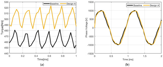
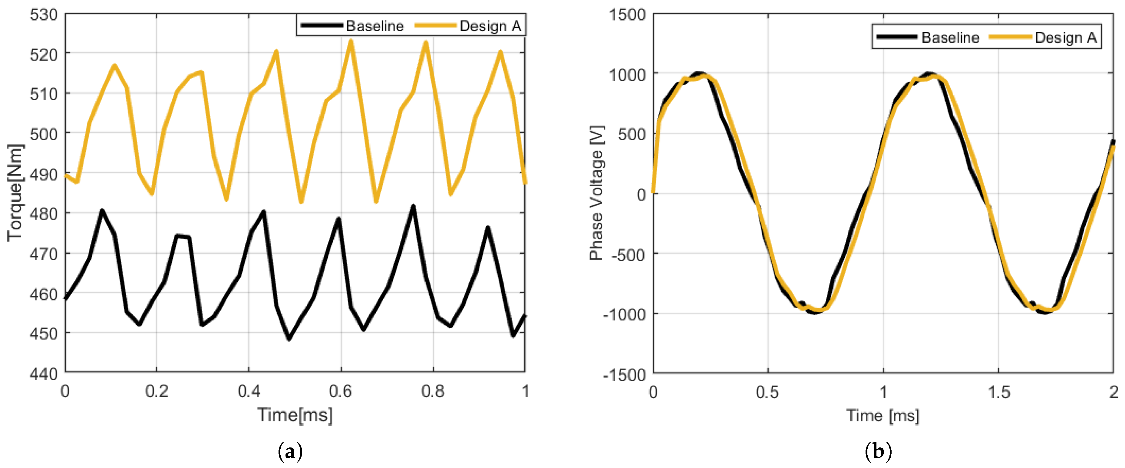
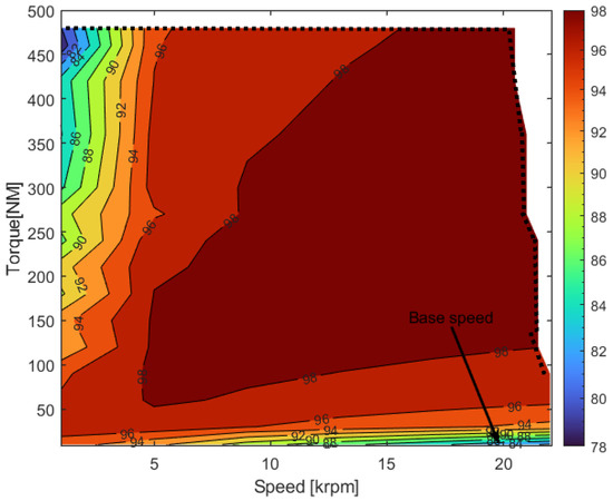
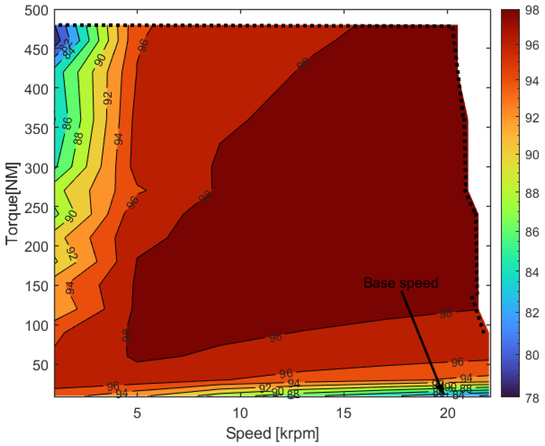
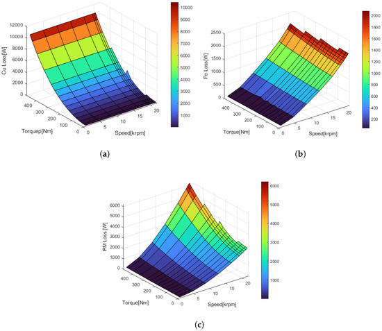
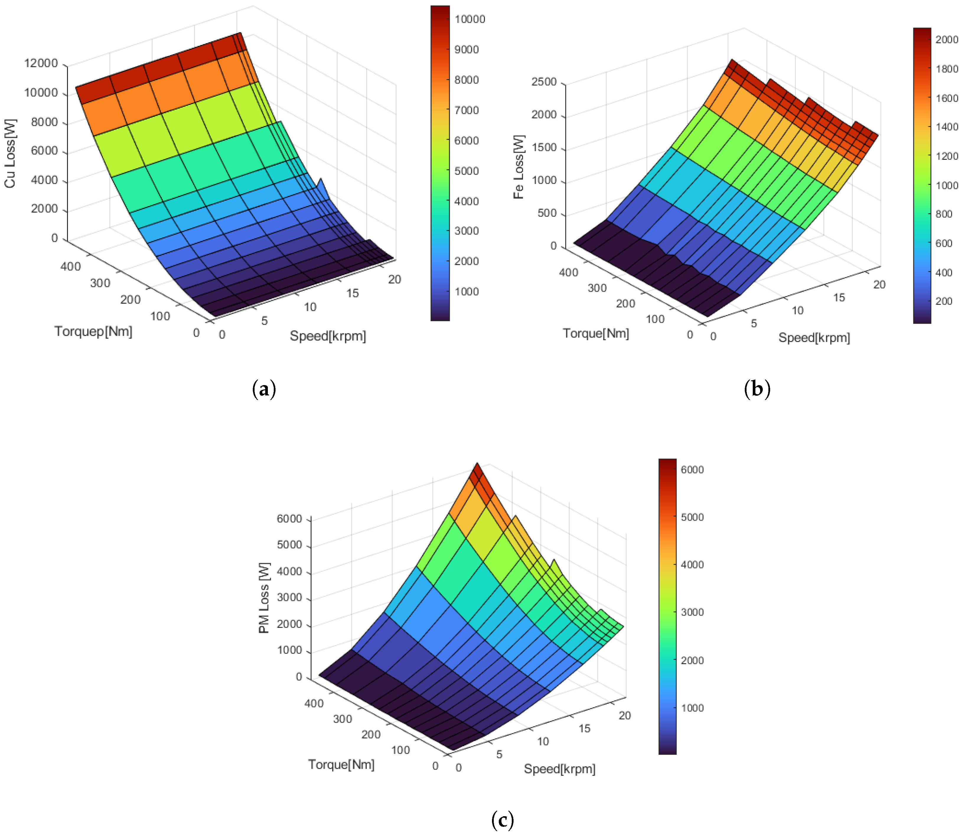
Figure 18 compares the torque waveform and per-phase voltage. The average electromagnetic torque increased by 10%, and the phase voltage decreased from 730 to 707 . The optimized design achieves a electromagnetic power density of 24.87 kW kg−1, representing a 6% improvement over the baseline model. The total estimated electromagnetic mass of the motor is with stationary parts and rotating parts 15.59 kg. Table 12 presents the component level active mass distribution. Figure 19 and Figure 20 present the efficiency and loss plots for the machine over a speed range of 500 rpm to 21,500 rpm, with 2D-FEM simulations. An efficiency above 98% is observed for the motor within the speed range of 5000 rpm to 20,000 rpm.
Figure 18.
Baseline vs. Design A: (a) Electromagnetic torque and (b) phase rms voltage.
Table 12.
Electromagnetic mass distribution.
Figure 19.
Efficiency Map of the machine.
Figure 20.
Loss plots of machine: (a) DC Copper Loss, (b) Iron Loss, and (c) PM Loss.
7. Computational Time Savings
By integrating a neural network surrogate model with a Genetic Algorithm within a multi-objective optimization framework, a more efficient approach to electric motor design is attained. The surrogate-based optimization significantly reduces simulation time compared to traditional finite element method optimization. To quantify the time savings, a comparison between the proposed algorithm and FEM-based simulations is provided in Table 13. The simulations were conducted on a computer with an Intel Core i7-9700 CPU running at 3.00 GHz and 64 GB of RAM. For this specific case, involving three objectives, three constraints, and six input and output variables, an optimal design was obtained after approximately 17 h of total simulation time. Out of the 17 h, the most time-consuming task involved the preparation of the data set for neural network training, which was conducted using 2D-FEM simulations that are unavoidable. The 2D- FEM transient simulation of the motor model requires approximately 80 s for execution, data saving, and post-processing, indicating that each FEM simulation takes about 80 s to complete. Once the data is collected and the NN is trained, the Genetic Algorithm optimization was able to identify an optimal design within 20 min, a duration primarily influenced by the GA parameter settings discussed in Section 5. Throughout the optimization process, the surrogate model was called 17,251 times; replacing it with FEM 2D- FEM model simulations would have resulted in approximately 14 days of computational time to reach an optimal design using GA.
Table 13.
Computational Time Savings with the Proposed Optimization method.
8. Thermal Analysis
Thermal boundaries fundamentally constrain the electromagnetic design of MW-class machines. The scaling of the electrical power output and volumetric losses is physically disproportionate to the increase in the machine size and the available effective cooling surface area accordingly. To ensure the thermal feasibility of the machine presented, the thermal performance of the stator is assessed with a maximum winding temperature of 180 °C. The analysis is performed using the losses of the optimal design presented in Table 11.
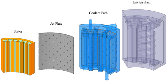
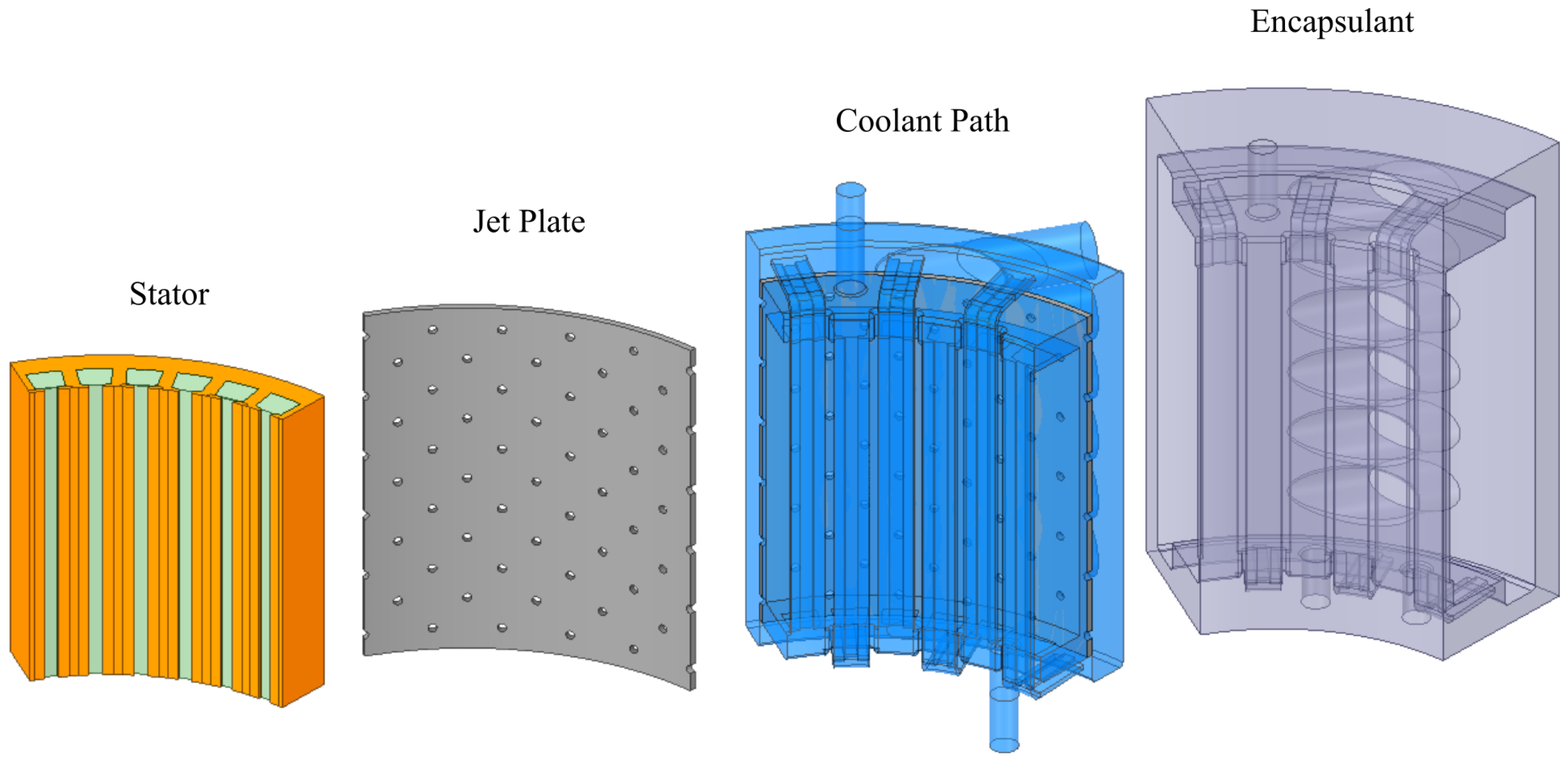
A stator cooling system is proposed utilizing a flooded stator architecture. The design combines two techniques: primarily, cooling the stator iron through a staggered array of jets and impinging coolant on its outer cylindrical surface, and secondarily, using a counter-flow cooling channels through the stator teeth to cool the stator region near the air gap, specifically the copper windings. Figure 21 shows the exploded view of 1/6th of the stator cooling system assembly.
Figure 21.
Exploded view of the stator cooling system assembly.
The cooling system is composed mainly of two main parts: an aluminum jet plate and the stator epoxy encapsulant. The stator is flooded with Automatic Transmission Fluid (ATF) used as the dielectric coolant. The epoxy encapsulant is designed to include internal cooling paths that control the fluid path through six distributed inlets at the stator circumference, delivering a total flow rate of 150 LPM. The coolant then passes through the jet plate, impinging on the stator iron, and exiting axially to two identical outlet manifolds. The outlet manifolds flood the top and bottom surfaces of the stator, including the end windings, providing further active cooling. Finally, the flow exits through 12 distributed outlets, which are divided equally over the top and bottom ends to avoid imbalances.
The secondary cooling loop consists of counterflow cooling channels of identical lengths. The cooling paths are embedded between the encapsulant and the stator inner diameter, actively cooling the windings. The cooling channels connect the inlet manifold and outlet manifolds, alternating the direction for each winding slot to avoid forming a thermal bias towards one end of the machine.
This cooling system is numerically assessed by performing a steady-state Conjugate Heat Transfer (CHT) Computational Fluid Dynamics simulation. The geometry is created to accurately capture the optimized stator dimensions and the cooling path details. A tetrahedral mesh of 8,930,068 elements is used to simulate 1/6th of the full stator, ensuring a mesh-independent solution. Inflation layers are added to the fluid–solid interface to ensure a non-dimensional wall distance, . ANSYS CFX (2025R1) is used to simulate the system using the K- SST turbulence model. Mass-flow inlet at 25 °C and a static-pressure outlet boundary conditions were used. The simulation convergence criterion is set to a minimum RMS residual value of 1 × 10⁻⁶ for the energy and momentum equations.
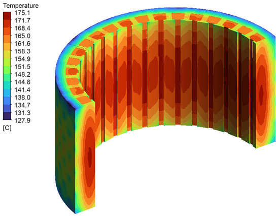
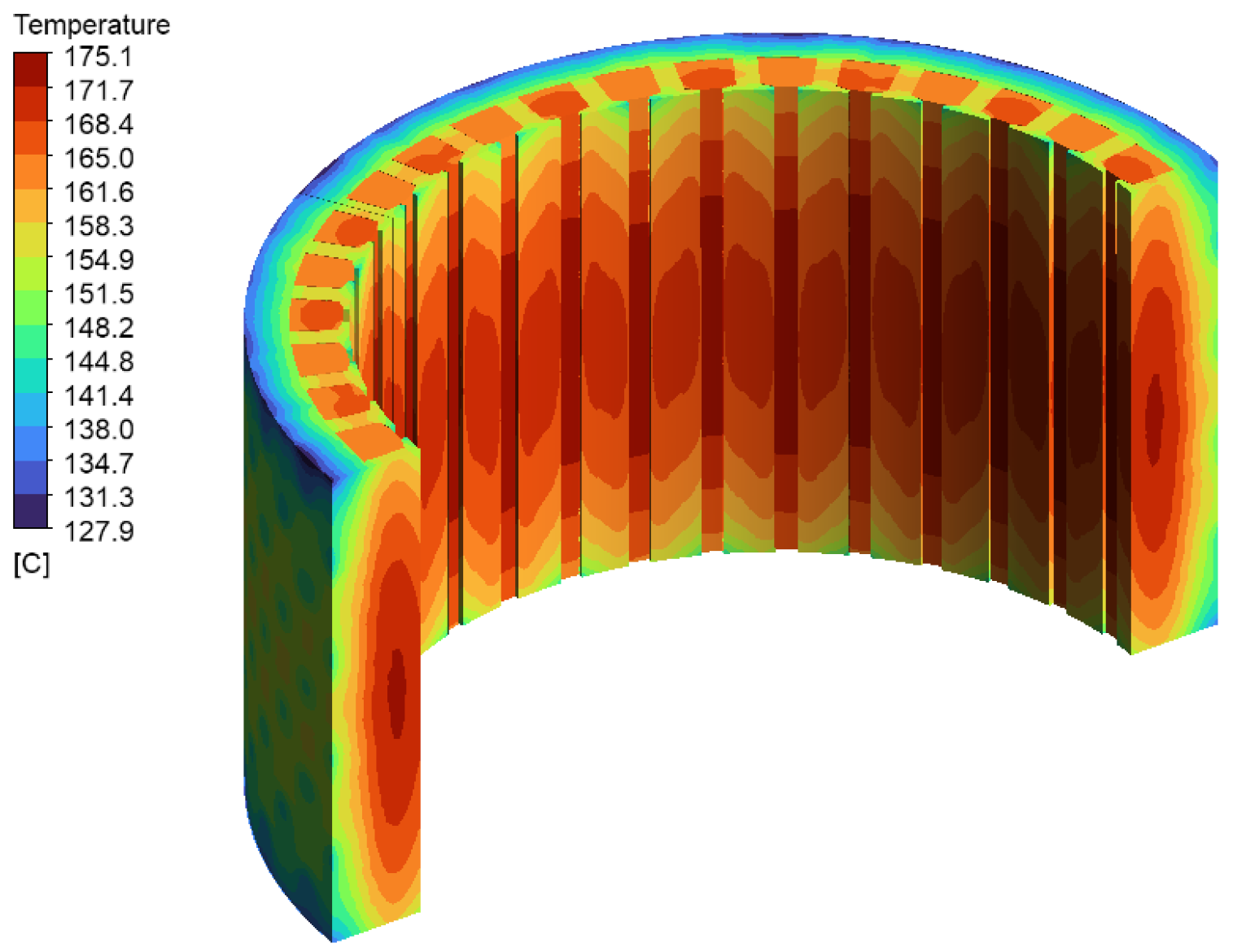
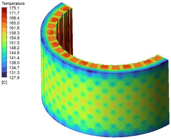
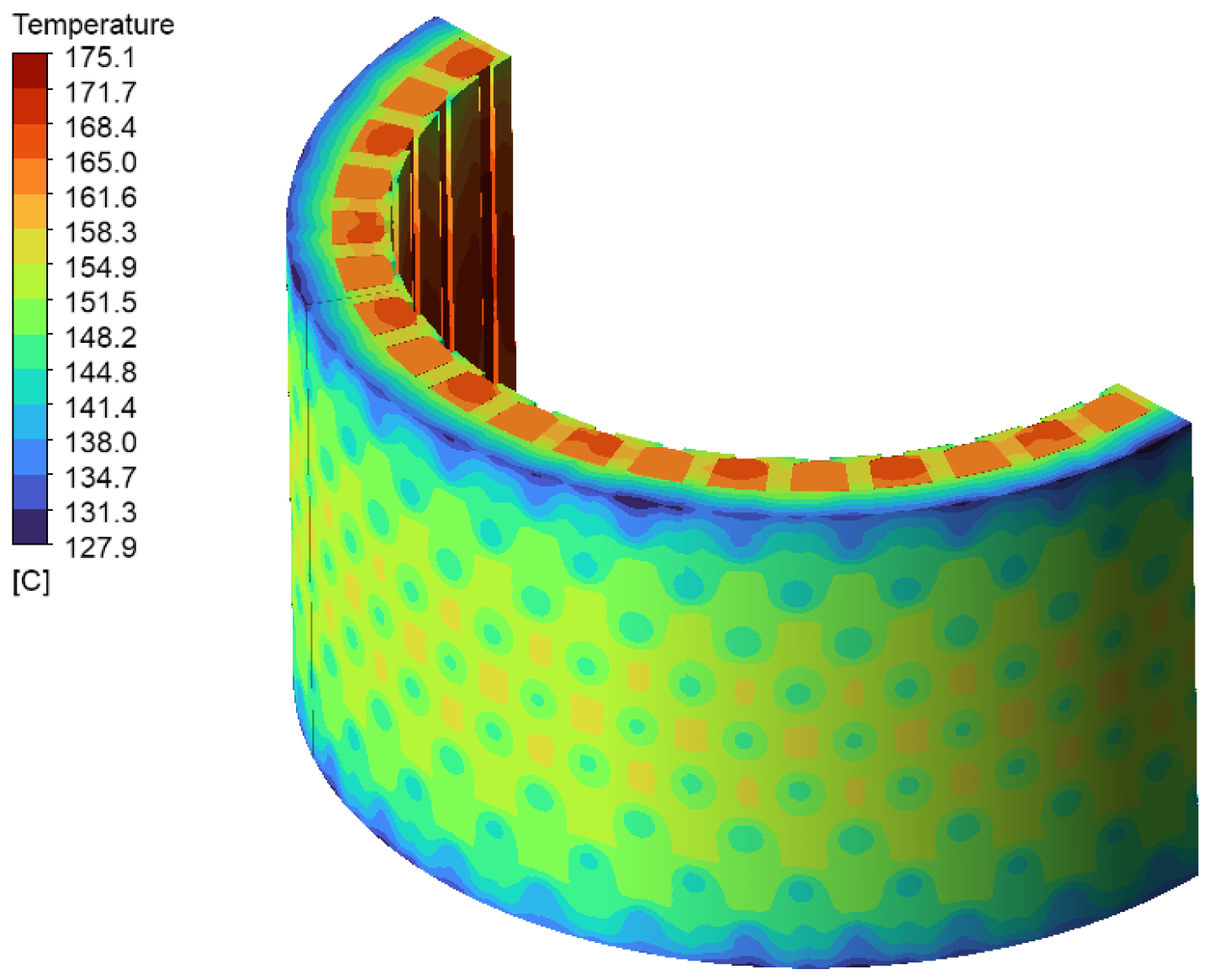
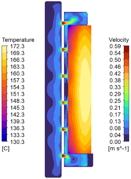
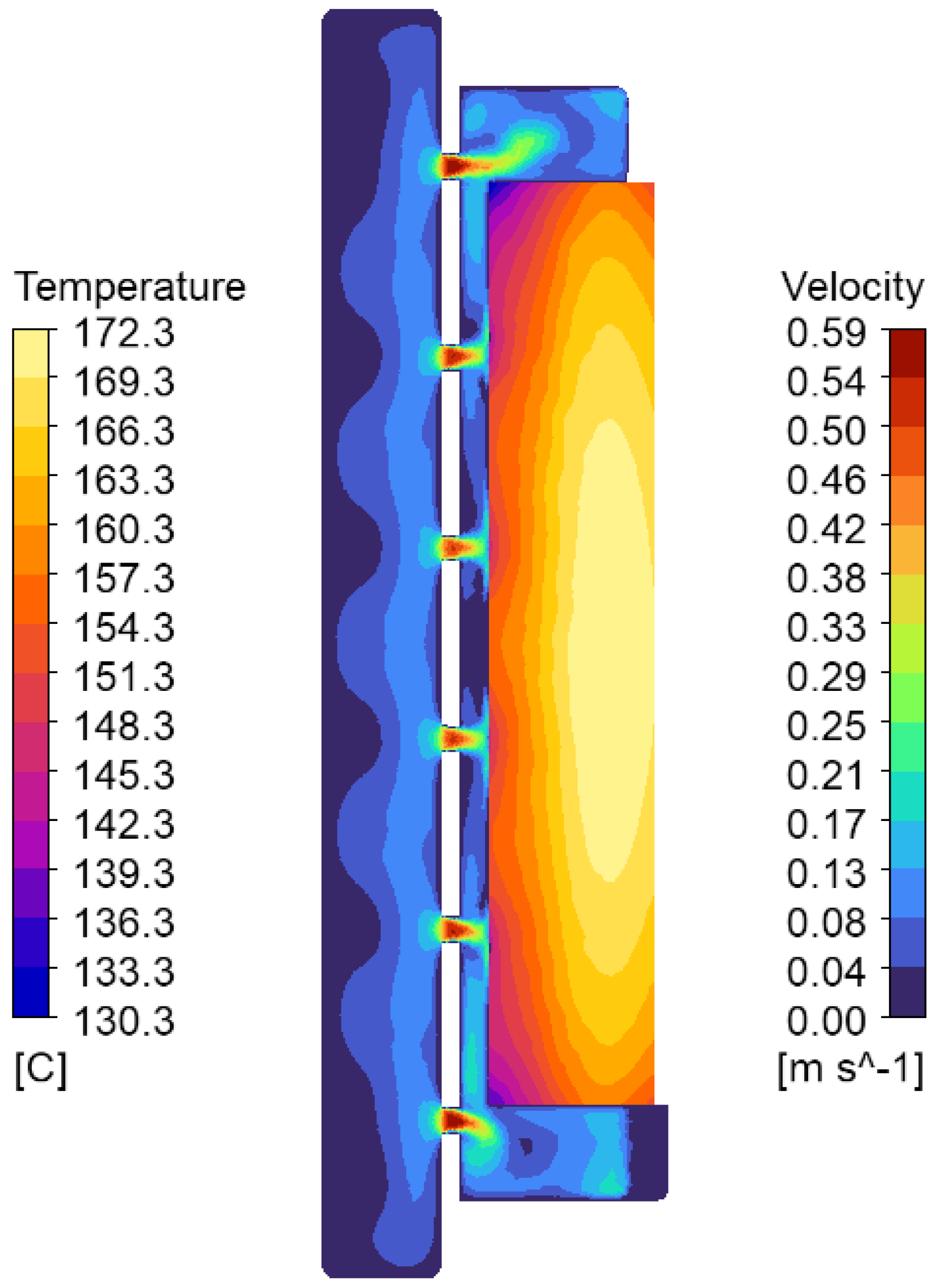
The results show efficient thermal management of the stator through the proposed system, maintaining the stator maximum temperature at 175 °C during continuous operation at the rated power output. Figure 22 shows the effectiveness of the cooling system in thermally balancing the stator temperatures to avoid local failure due to hotspots, thanks to the counterflow cooling channels. Furthermore, Figure 23 and Figure 24 show the temperature distribution and the corresponding velocity contours on the stator iron surface. The analysis highlights the feasibility of the optimized electromagnetic design with the concept cooling system, showing safe operating temperatures during continuous rated power output.
Figure 22.
Temperature distribution on the stator and windings.
Figure 23.
Temperature distribution on the stator iron showing temperature local minima due to jet impingement.
Figure 24.
Coolant flow velocity contours of jet impingement cooling on the stator iron.
9. Demagnetization Analysis
As mentioned in Section 2, in this study, the normal operating temperature of the magnet is considered as 100 °C assuming an efficient rotor cooling. Since both the maximum service temperature of the adhesive selected and the maximum operating temperature of the magnet N48UH are 180 °C, the rotor cannot be exposed to a higher temperature. Hence, considering the safety factor, the maximum operating temperature of the magnet is fixed at 170 °C for demagnetization analysis.
Increased operating temperatures in permanent magnet materials can alter their position on the magnetic hysteresis loop. When temperatures exceed safe limits, the magnetic operating point may drop beneath the critical knee region of the curve, potentially resulting in permanent loss of magnetic properties [53].
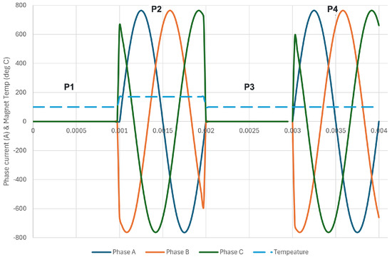
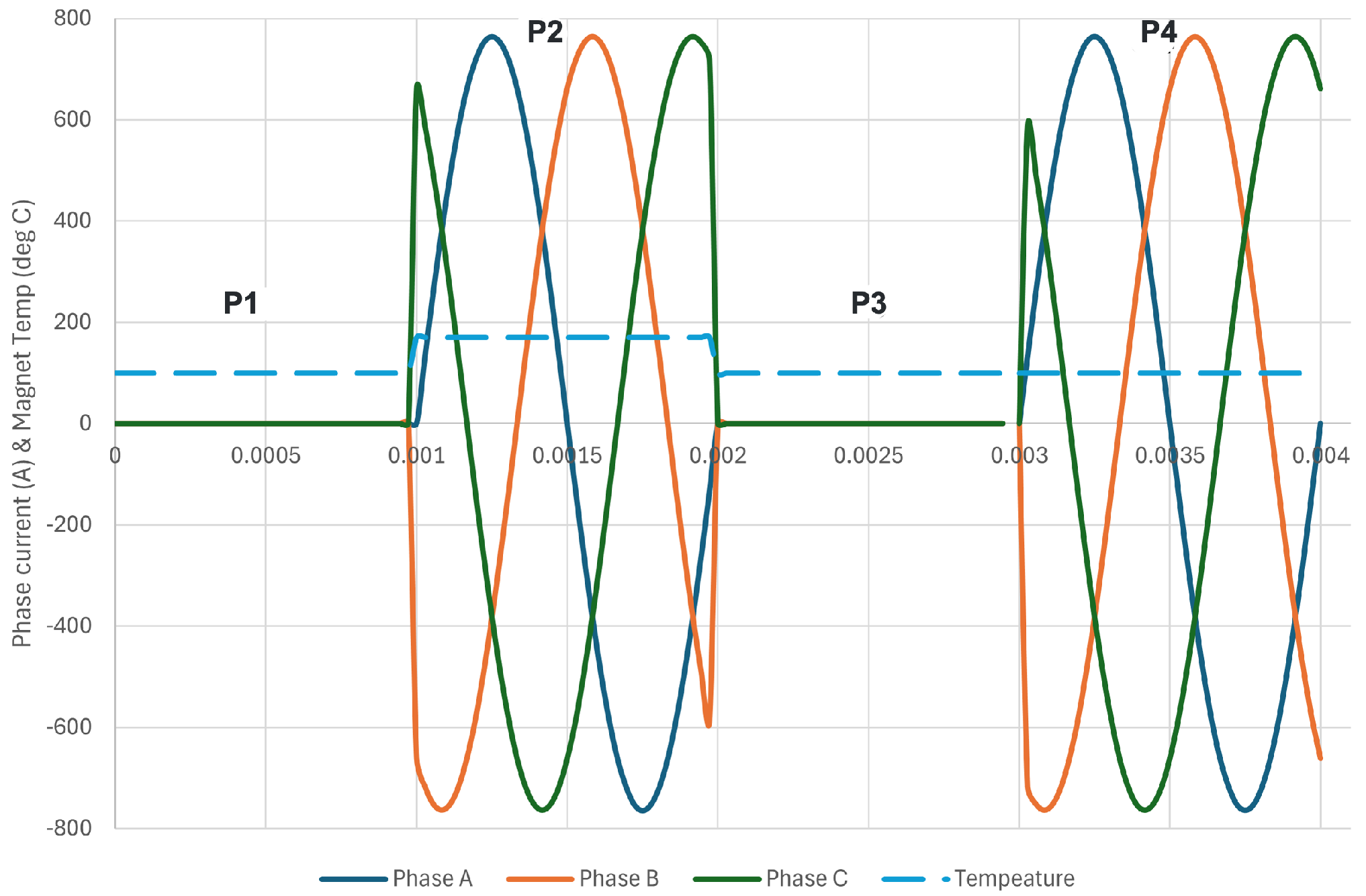
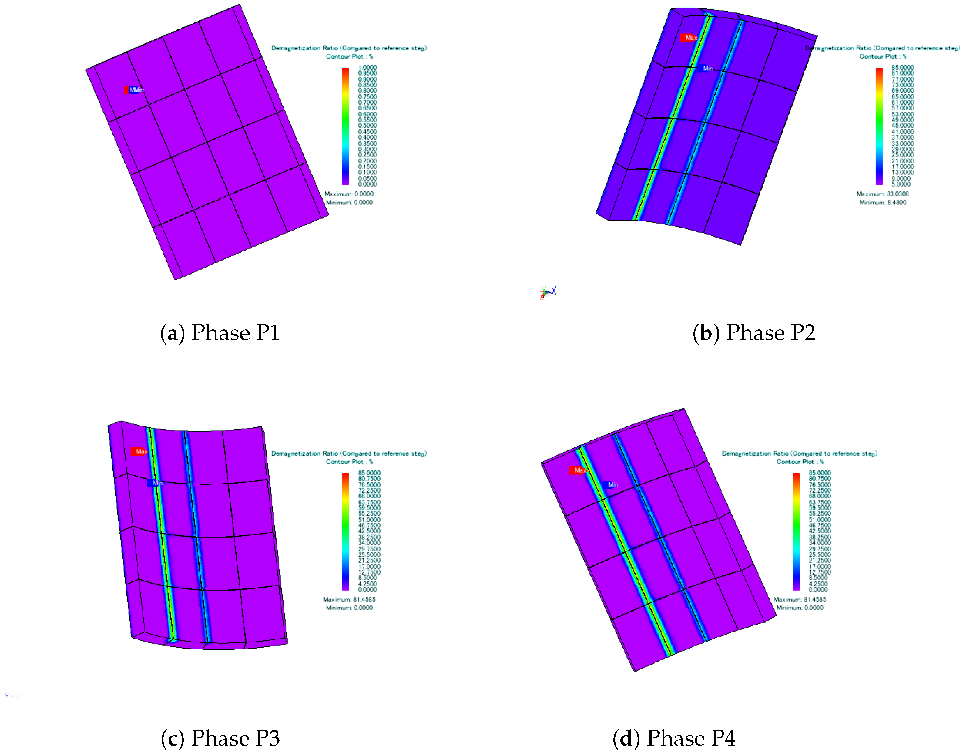
To examine how temperature variations affect magnet performance, analysis was conducted across four operational phases (P1, P2, P3, and P4), illustrated in Figure 25. Phases P1 and P3 represent no-load conditions, while P2 and P4 simulate full-load scenarios. Throughout phases P1, P3, and P4, the permanent magnet operates at 100 °C, whereas during P2, the temperature increased to 170 °C to represent extreme operating conditions. The induced EMF from phases P1 and P3 are compared to evaluate whether permanent demagnetization has occurred. Any irreversible magnetic degradation would change the induced EMF patterns due to changes in the residual magnetic flux density.
Figure 25.
Four phases of operation: phase currents and temperature.
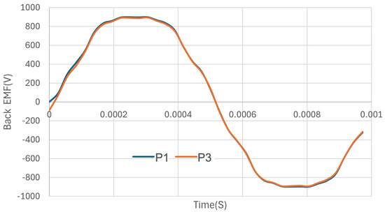
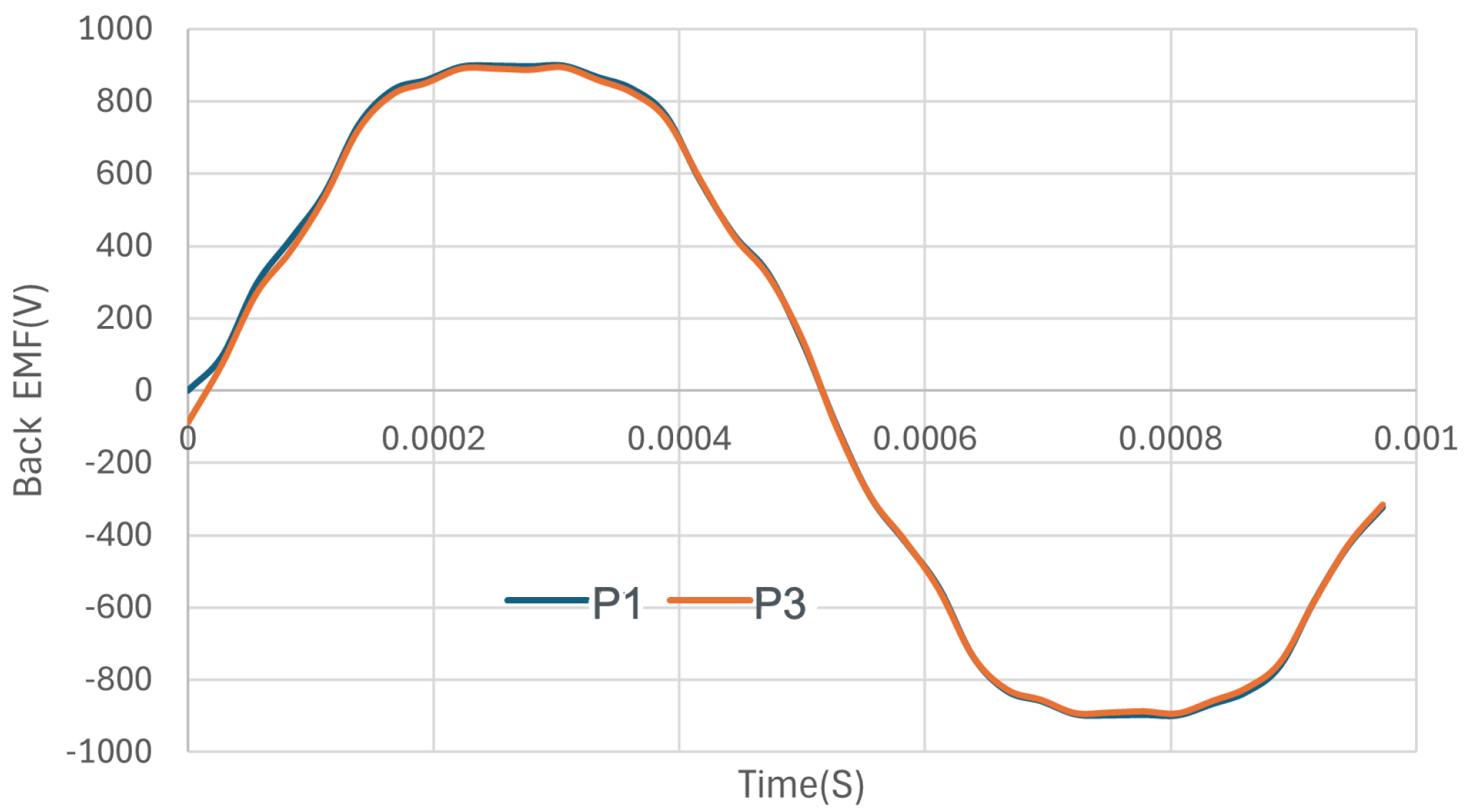
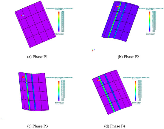
Figure 26 shows the back EMF waveform during phases P1 and P3. The PM demagnetizes during P2 but is reversible and hence does not lead to permanent demagnetization. Slight partial irreversible demagnetization is formed at the edges of the magnet segment-2, which is depicted in demagnetization contour plot (Figure 27). However, this has not affected the airgap flux, and hence the back EMFs at phases P1 and P3 are the same. The machine could also deliver rated power (torque 500 N·m) when operated with the full-load current after the demagnetizing cycle. Hence, the analysis shows no risk of demagnetization.
Figure 26.
Back EMF phases P1 and P3.
Figure 27.
Demagnetization Ratio Visualization.
10. Conclusions
To achieve the net-zero carbon emission targets in the aviation industry, a key objective in aircraft electrification is replacing conventional propulsion systems with hybrid and fully electric alternatives. This transition demands the design and development of high-power-density electric motors. This paper presents the design of a 36/6, 20,000 rpm, 1 radial flux permanent magnet motor for propulsion applications. It systematically details a hybridized algorithm that combines an Artificial Neural Network surrogate model with a Genetic Algorithm for the multi-objective optimization of the motor. This method significantly reduces simulation time by approximately 95% compared to traditional finite element approaches. The algorithm effectively produces an enhanced megawatt-class motor design, achieving a projected electromagnetic efficiency of 98% and power density of 24.87 kW kg−1, both above the NASA’s target goals for 2030. Furthermore, comprehensive electromagnetic analysis validates the proposed machine design. To demonstrate design feasibility, a detailed stator cooling system incorporating jet impingement technology is presented. Results demonstrate that this cooling configuration successfully maintains stator temperatures below critical thermal limits. Although the rotor cooling system design remains beyond scope, the analysis assumes an efficient rotor cooling system and a detailed magnet demagnetization risk analysis is presented.
Several promising research directions emerge from this work to further advance high-power aerospace motor design. Developing an efficient rotor cooling system, given the thermal challenges inherent in high-speed, high-power-density applications, is one direction. The effects of high frequency on the losses both stator core and winding should be investigated in detail, incorporating the strand-level modeling to capture skin and proximity effects accurately. Design solutions using advancements in additive manufacturing and development in other winding technologies like Litz wire could be considered to improve the design further. This could improve the machine’s thermal management, efficiency and power density. Efforts have been made in this study to analyze the loss reduction with permanent magnet axial segmentation. However, the possibility of using a Snakeline design, which could reduce the complexity of magnet mounting and, at the same time, add flexibility to more segmentation within a bar of the magnet, is also an interesting point to consider.
Author Contributions
Conceptualization, S.P. and M.A.; methodology, S.P., I.Z. and M.A.; software, S.P. and I.Z.; validation, S.P. and I.Z.; formal analysis, S.P. and I.Z.; investigation, S.P.; data curation, S.P.; writing—original draft preparation, S.P. and I.Z.; writing—review and editing, S.P., I.Z. and M.A.; visualization, S.P.; supervision, A.E. All authors have read and agreed to the published version of the manuscript.
Funding
This research received no external funding.
Data Availability Statement
The data are not publicly available due to privacy. The data presented in this study are available on request from the corresponding author.
Acknowledgments
The authors acknowledge POWERSYS Corporation for their support with JMAG software (Ver.24.0), Ansys for their support with ANSYS CFX ANSYS CFX (2025R1) software and MathWorks for their support with MATLAB and Simulink (R2025b) software.
Conflicts of Interest
The authors declare no conflicts of interest.
Abbreviations
The following abbreviations are used in this manuscript:
| ANN | Artificial Neural Network |
| MEA | More Electric Aircraft |
| NASA | National Aeronautics and Space Administration |
| PMSM | Permanent Magnet Synchronous Machine |
| SPMSM | Permanent Magnet Synchronous Machine |
| FEM | Finite Element Methods |
| FEA | Finite Element Analysis |
| IATA | International Air Transport Association |
| eVTOL | Electric Vertical Take-off and Landing |
| MOO | Multi-Objective Optimization |
| ML | Machine Learning |
| GA | Genetic Algorithm |
| NN | Neural Network |
| MLP | Multi-layer Perceptron |
| LM | Levenberg Marquardt |
| BPNN | Backpropagation Neural Network |
| MSE | Mean Square Error |
References
- Wheeler, P.; Sirimanna, T.S.; Bozhko, S.; Haran, K.S. Electric/Hybrid-Electric Aircraft Propulsion Systems. Proc. IEEE 2021, 109, 1115–1127. [Google Scholar] [CrossRef] [Scilit]
- Arabul, A.Y.; Kurt, E.; Arabul, F.K.; İbrahim, S.; Schrötter, M.; Bréda, R.; Megyesi, D. Perspectives and Development of Electrical Systems in More Electric Aircraft. Int. J. Aerosp. Eng. 2021, 2021, 5519842. [Google Scholar] [CrossRef] [Scilit]
- Ansell, P.J.; Haran, K.S. Electrified Airplanes: A Path to Zero-Emission Air Travel. IEEE Electrif. Mag. 2020, 8, 18–26. [Google Scholar] [CrossRef] [Scilit]
- Gerada, D.; Mebarki, A.; Brown, N.L.; Gerada, C.; Cavagnino, A.; Boglietti, A. High-speed electrical machines: Technologies, trends, and developments. IEEE Trans. Ind. Electron. 2014, 61, 2946–2959. [Google Scholar] [CrossRef] [Scilit]
- Brelje, B.J.; Martins, J.R. Electric, hybrid, and turboelectric fixed-wing aircraft: A review of concepts, models, and design approaches. Prog. Aerosp. Sci. 2019, 104, 1–19. [Google Scholar] [CrossRef] [Scilit]
- Lukic, M.; Giangrande, P.; Hebala, A.; Nuzzo, S.; Galea, M. Review, Challenges, and Future Developments of Electric Taxiing Systems. IEEE Trans. Transp. Electrif. 2019, 5, 1441–1457. [Google Scholar] [CrossRef] [Scilit]
- Rosero, J.; Ortega, J.; Aldabas, E.; Romeral, L. Moving towards a More Electric Aircraft. IEEE Aerosp. Electron. Syst. Mag. 2007, 22, 3–9. [Google Scholar] [CrossRef] [Scilit]
- Airbus. 2023. Available online: https://www.airbus.com/en/innovation/low-carbon-aviation/hybrid-and-electric-flight/ecopulse (accessed on 20 November 2025).
- Ganev, E.D. High-Performance Electric Drives for Aerospace More Electric Architectures Part I—Electric Machines. In Proceedings of the 2007 IEEE Power Engineering Society General Meeting, Tampa, FL, USA, 24–28 June 2007; pp. 1–8. [Google Scholar] [CrossRef] [Scilit]
- Liu, Y.; Mo, D.; Nalianda, D.; Li, Y.; Roumeliotis, I. Review of More Electric Engines for Civil Aircraft. Int. J. Aeronaut. Space Sci. 2022, 23, 784–793. [Google Scholar] [CrossRef] [Scilit]
- Adu-Gyamfi, B.A.; Good, C. Electric aviation: A review of concepts and enabling technologies. Transp. Eng. 2022, 9, 100134. [Google Scholar] [CrossRef] [Scilit]
- Lisovin, I.G.; Ismagilov, F.R.; Vavilov, V.E.; Dadoyan, R.G.; Pronin, E.A. A Review of Critical Technologies for Making a More Electric Engine. J. Mach. Manuf. Reliab. 2022, 51, S132–S147. [Google Scholar] [CrossRef] [Scilit]
- Alvarez, P.; Satrustegui, M.; Elosegui, I.; Martinez-Iturralde, M. Review of High Power and High Voltage Electric Motors for Single-Aisle Regional Aircraft. IEEE Access 2022, 10, 112989–113004. [Google Scholar] [CrossRef] [Scilit]
- Sayed, E.; Abdalmagid, M.; Pietrini, G.; Sa’adeh, N.M.; Callegaro, A.D.; Goldstein, C.; Emadi, A. Review of Electric Machines in More-/Hybrid-/Turbo-Electric Aircraft. IEEE Trans. Transp. Electrif. 2021, 7, 2976–3005. [Google Scholar] [CrossRef] [Scilit]
- Jansen, R.; Bowman, C.; Jankovsky, A.; Dyson, R.; Felder, J. Overview of NASA Electrified Aircraft Propulsion (EAP) Research for Large Subsonic Transports. In Proceedings of the 53rd AIAA/SAE/ASEE Joint Propulsion Conference, Atlanta, GA, USA, 10–12 July 2017. [Google Scholar] [CrossRef] [Scilit]
- Granger, M.; Anderson, A.; Maroli, J.M.; Tallerico, T.; Scheidler, J.J. Combined Analysis of NASA’s High Efficiency Megawatt Motor and Its Converter. In Proceedings of the AIAA Propulsion and Energy Forum, Virtual, 9–11 August 2021. [Google Scholar] [CrossRef] [Scilit]
- Tenconi, A.; Vaschetto, S.; Vigliani, A. Electrical machines for high-speed applications: Design considerations and tradeoffs. IEEE Trans. Ind. Electron. 2014, 61, 3022–3029. [Google Scholar] [CrossRef] [Scilit]
- El-Refaie, A.; Osama, M. High specific power electrical machines: A system perspective. In Proceedings of the 2017 20th International Conference on Electrical Machines and Systems (ICEMS), Sydney, NSW, Australia, 11–14 August 2017; pp. 1–6. [Google Scholar] [CrossRef] [Scilit]
- eHelix. SPX130 Electric Motor. Available online: https://www.ehelix.com/products/spx130-electric-motor/ (accessed on 20 November 2025).
- Magnix. Powertrains—Magnix. Available online: https://www.magnix.aero/powertrains (accessed on 20 November 2025).
- H3X Technologies. About Us—H3X Technologies. Available online: https://www.h3x.tech/#about-us (accessed on 20 November 2025).
- EMRAX E-Motors. 2023. Available online: https://emrax.com/e-motors/ (accessed on 20 November 2025).
- Evolito. Axial-Flux Motors—Evolito. Available online: https://evolito.aero/axial-flux-motors/ (accessed on 20 November 2025).
- Siemens. Transitioning Aircraft Propulsion from Carbon to Electrons. Available online: https://blogs.sw.siemens.com/thought-leadership/transitioning-aircraft-propulsion-from-carbon-to-electrons/ (accessed on 20 November 2025).
- Safran Group. ENGINeUS™—Safran Group. Available online: https://www.safran-group.com/products-services/engineustm (accessed on 20 November 2025).
- Rolls-Royce. Regional Air Mobility. Available online: https://www.rolls-royce.com/~media/Files/R/Rolls-Royce/documents/others/rolls-royce-regional-air-mobility.pdf (accessed on 20 November 2025).
- Honeywell. Honeywell 1 Megawatt (MW) Turbogenerator. Available online: https://aerospace.honeywell.com/us/en/products-and-services/products/power-and-propulsion/electric-power/honeywell-1-megawatt-mw-turbogenerator (accessed on 20 November 2025).
- Sawata, T.; Minshull, S. Development of 1 MW Hybrid Electric Propulsion Drive System. In Proceedings of the 2024 IEEE International Conference on Electrical Systems for Aircraft, Railway, Ship Propulsion and Road Vehicles & International Transportation Electrification Conference (ESARS-ITEC), Naples, Italy, 26–29 November 2024; pp. 1–6. [Google Scholar] [CrossRef] [Scilit]
- Yoon, A.; Yi, X.; Martin, J.; Chen, Y.; Haran, K. A high-speed, high-frequency, air-core PM machine for aircraft application. In Proceedings of the 2016 IEEE Power and Energy Conference at Illinois (PECI), Urbana, IL, USA, 19–20 February 2016; pp. 1–4. [Google Scholar] [CrossRef] [Scilit]
- Golovanov, D.; Gerada, D.; Sala, G.; Degano, M.; Trentin, A.; Connor, P.H.; Xu, Z.; Rocca, A.L.; Galassini, A.; Tarisciotti, L.; et al. 4-MW Class High-Power-Density Generator for Future Hybrid-Electric Aircraft. IEEE Trans. Transp. Electrif. 2021, 7, 2952–2964. [Google Scholar] [CrossRef] [Scilit]
- Huynh, A.T.; Huang, H.; Jiang, J.; Zou, T.; Gerada, D.; Yang, T.; Gerada, C.; Hsieh, M.F. Design of a 1MW-Class Permanent Magnet Machine Featuring Multiphase Hairpin Windings for Electric Aircraft Propulsion. In Proceedings of the 2024 IEEE Vehicle Power and Propulsion Conference (VPPC), Washington, DC, USA, 7–10 October 2024; pp. 1–6. [Google Scholar] [CrossRef] [Scilit]
- Mikkelsen, E.K.; Matveev, A.; Nøland, J.K. High-Speed MW-Class Generator With Multi-Lane Slotless Winding for Hybrid-Electric Aircraft. IEEE Access 2023, 11, 84759–84771. [Google Scholar] [CrossRef] [Scilit]
- Dowdle, A.P. Design of a High Specific Power Electric Machine for Turboelectric Propulsion. Ph.D. Thesis, Massachusetts Institute of Technology, Cambridge, MA, USA, 2022. [Google Scholar]
- Wang, J.; Jahns, T.M.; McCluskey, P.; Kizito, J.; Sarlioglu, B.; Borjas, R.; Swanke, J.A.; Cong, Y.; Yao, Z.; Zeng, H.; et al. 2-kV 1-MW 20,000-r/min Integrated Modular Motor Drive for Electrified Aircraft Propulsion. IEEE J. Emerg. Sel. Top. Power Electron. 2025, 13, 394–407. [Google Scholar] [CrossRef] [Scilit]
- Pang, Y.; Zhu, Z.; Howe, D. Analytical determination of optimal split ratio for permanent magnet brushless motors. IEE Proc.-Electr. Power Appl. 2006, 153, 7–13. [Google Scholar] [CrossRef] [Scilit]
- Chen, X.; Zhu, Z.Q. Analytical determination of optimal split ratio of E-core permanent magnet linear oscillating actuators. In Proceedings of the 2009 IEEE Energy Conversion Congress and Exposition, San Jose, CA, USA, 20–24 September 2009; pp. 2100–2107. [Google Scholar] [CrossRef] [Scilit]
- Shen, Y.; Zhu, Z.Q. Analytical Prediction of Optimal Split Ratio for Fractional-Slot External Rotor PM Brushless Machines. IEEE Trans. Magn. 2011, 47, 4187–4190. [Google Scholar] [CrossRef] [Scilit]
- Lei, G.; Bramerdorfer, G.; Ma, B.; Guo, Y.; Zhu, J. Robust Design Optimization of Electrical Machines: Multi-Objective Approach. IEEE Trans. Energy Convers. 2021, 36, 390–401. [Google Scholar] [CrossRef] [Scilit]
- Liu, A.; Huang, X.; Chen, Z.; Ma, Y.; Yu, Y.; Li, Z. Nonlinear Analytical Model-Embedded Optimal Design for ER-PMSM. IEEE Trans. Magn. 2024, 60, 1–5. [Google Scholar] [CrossRef] [Scilit]
- Liu, L.; Ma, Y.; Wang, R.; Li, Z.; Sun, L.; Zhao, H. Robust Optimization of a Stator Tooth Chamfering IPMSM for Electric Power Steering Applications. In Proceedings of the 2024 International Conference on Electrical Machines (ICEM), Torino, Italy, 1–4 September 2024; pp. 1–7. [Google Scholar] [CrossRef] [Scilit]
- Ahmed, S.; Grabher, C.; Kim, H.J.; Koseki, T. Multifidelity Surrogate Assisted Rapid Design of Transverse-Flux Permanent Magnet Linear Synchronous Motor. IEEE Trans. Ind. Electron. 2020, 67, 7280–7289. [Google Scholar] [CrossRef] [Scilit]
- Gu, J.; Hua, W.; Yu, W.; Zhang, Z.; Zhang, H. Surrogate Model-Based Multiobjective Optimization of High-Speed PM Synchronous Machine: Construction and Comparison. IEEE Trans. Transp. Electrif. 2023, 9, 678–688. [Google Scholar] [CrossRef] [Scilit]
- Cho, H.W.; Jang, S.M.; Choi, S.K. A Design Approach to Reduce Rotor Losses in High-Speed Permanent Magnet Machine for Turbo-Compressor. IEEE Trans. Magn. 2006, 42, 3521–3523. [Google Scholar] [CrossRef] [Scilit]
- Bao, J.; Xing, J.; Luo, Y.; Zheng, P. Multi-objective shape optimization of Permanent Magnet Synchronous Motor based on Kriging surrogate model and design domain reduction. In Proceedings of the 2019 22nd International Conference on Electrical Machines and Systems (ICEMS), Harbin, China, 11–14 August 2019; pp. 1–4. [Google Scholar] [CrossRef] [Scilit]
- Pop, A.C.; Cai, Z.; Gyselinck, J.J.C. Machine-Learning Aided Multiobjective Optimization of Electric Machines— Geometric-Feasibility and Enhanced Regression Models. IEEE J. Emerg. Sel. Top. Ind. Electron. 2023, 4, 844–854. [Google Scholar] [CrossRef] [Scilit]
- Dhulipati, H.; Ghosh, E.; Mukundan, S.; Korta, P.; Tjong, J.; Kar, N.C. Advanced Design Optimization Technique for Torque Profile Improvement in Six-Phase PMSM Using Supervised Machine Learning for Direct-Drive EV. IEEE Trans. Energy Convers. 2019, 34, 2041–2051. [Google Scholar] [CrossRef] [Scilit]
- Yu, Y.; Pan, Y.; Chen, Q.; Hu, Y.; Gao, J.; Zhao, Z.; Niu, S.; Zhou, S. Multi-Objective Optimization Strategy for Permanent Magnet Synchronous Motor Based on Combined Surrogate Model and Optimization Algorithm. Energies 2023, 16, 1630. [Google Scholar] [CrossRef] [Scilit]
- Sun, H.; Krebs, G.; Bahri, I.; Rodriguez-Ayerbe, P.; Khanchoul, M. PMSM design optimization concerning sensorless performance and torque ripple. E-Prime—Adv. Electr. Eng. Electron. Energy 2022, 2, 100049. [Google Scholar] [CrossRef] [Scilit]
- Kim, S.e.; You, Y.m. Optimization of a Permanent Magnet Synchronous Motor for e-Mobility Using Metamodels. Appl. Sci. 2022, 12, 1625. [Google Scholar] [CrossRef] [Scilit]
- Benlamine, R.; Dubas, F.; Randi, S.A.; Lhotellier, D.; Espanet, C. Design by optimization of an axial-flux permanent-magnet synchronous motor using Genetic Algorithms. In Proceedings of the 2013 International Conference on Electrical Machines and Systems (ICEMS), Busan, Republic of Korea, 26–29 October 2013; pp. 13–17. [Google Scholar] [CrossRef] [Scilit]
- Zhao, X.; Sun, Z.; Xu, Y. Multi-Objective Optimization Design of Permanent Magnet Synchronous Motor Based on Genetic Algorithm. In Proceedings of the 2020 2nd International Conference on Machine Learning, Big Data and Business Intelligence (MLBDBI), Taiyuan, China, 23–25 October 2020; pp. 405–409. [Google Scholar] [CrossRef] [Scilit]
- Amaidi, M.; Mansouri, A. Genetic Algorithm based Multi-objective optimization of SMPM. In Proceedings of the 2023 20th International Multi-Conference on Systems, Signals & Devices (SSD), Mahdia, Tunisia, 20–23 February 2023; pp. 633–636. [Google Scholar] [CrossRef] [Scilit]
- Pillai, S.; Forsyth, A.; Abdalmagid, M.; Doan, J.; Pietrini, G.; Suntharalingam, P.; Goykhman, M.; Emadi, A. Demagnetization Analysis of a High-Speed PMSM for an Aerospace Application. In Proceedings of the 2023 IEEE International Electric Machines & Drives Conference (IEMDC), San Francisco, CA, USA, 15–18 May 2023; pp. 1–7. [Google Scholar] [CrossRef] [Scilit]


Disclaimer/Publisher’s Note: The statements, opinions and data contained in all publications are solely those of the individual author(s) and contributor(s) and not of MDPI and/or the editor(s). MDPI and/or the editor(s) disclaim responsibility for any injury to people or property resulting from any ideas, methods, instructions or products referred to in the content. |
© 2026 by the authors. Licensee MDPI, Basel, Switzerland. This article is an open access article distributed under the terms and conditions of the Creative Commons Attribution (CC BY) license.