


Abstract
Humanoid manipulators with kinematic redundancy offer enhanced dexterity and adaptability to complex environments. Solving their inverse kinematics (IK) is fundamental to trajectory tracking, motion planning, and real-time control. Conventional Jacobian-based iterative methods are widely used, but they are often sensitive to the initial guess, computationally expensive, and less effective in handling strict constraints. Arm-angle-based analytical parameterization reduces redundancy resolution to a single parameter. However, joint limits may lead to multiple disconnected feasible arm-angle intervals. Many existing methods still depend on a numerical search or intelligent optimization to select the arm angle. This lowers computational efficiency and provides less explicit control over branch and configuration selection. To address these issues, this paper extends the arm-angle analytical IK framework. It introduces global configuration parameters to explicitly control the shoulder-elbow-wrist configuration. It also completes the analytical derivation of the rotational relationships of the first three joints in the reference plane. In addition, a feasibility determination and modeling scheme for the arm-angle domain is established, which covers disconnected feasible intervals. The IK problem is then reformulated as a one-dimensional optimization over the feasible domain. An efficient interval-based search is employed to determine the optimal arm angle. Experimental results demonstrate high accuracy and interference-free trajectory tracking. Comparative tests on randomly sampled target poses are also performed. The results show more concentrated error distributions, shorter average computation time, and higher success rates. These results confirm the advantages of the proposed method in accuracy, robustness, and real-time performance.
1. Introduction
The research on humanoid seven-degree-of-freedom (7-DOF) redundant manipulators is of significant importance in the field of robotics, particularly due to their design that mimics the human arm [1]. With the redundancy provided by seven degrees of freedom, humanoid manipulators can achieve flexible movement and precise operation similar to that of the human arm, enhancing their adaptability in complex environments. Compared to six-degree-of-freedom manipulators, humanoid manipulators are better equipped to avoid obstacles, optimize motion paths, and perform tasks efficiently in confined spaces [2]. Additionally, the redundant degrees of freedom enable the manipulator to optimize force and pose during multi-task execution, improving the stability and reliability of operations [3]. With the advancement of kinematic theory and technological progress, humanoid seven-degree-of-freedom redundant manipulators have been widely applied in fields such as industrial automation [4], medical surgery [5], and deep space exploration [6].
Inverse kinematics (IK) plays a crucial role in the motion control of manipulators. It allows for the calculation of joint angles based on the desired position and orientation of the end-effector, forming the foundation for precise manipulation. Research on inverse kinematics methods improves motion planning efficiency and accuracy, but also helps address issues such as collision avoidance and energy consumption during manipulator motion. Through effective inverse kinematics algorithms, more flexible and efficient motion planning strategies can be provided, enhancing the adaptability of manipulators in complex-tasks.
Currently, the IK solutions for redundant manipulators primarily include algebraic methods, geometric methods [7,8,9], numerical optimization methods [10,11,12], and pseudo-inverse methods [13,14,15]. Among these, the pseudol-inverse method is commonly used to address redundancy problems, but it has high computational complexity and struggles to handle constraints effectively. In contrast, the arm-angle method transforms the redundancy problem into a constrained optimization problem, directly incorporating constraints into the computation. This approach offers higher computational efficiency and operability. Particularly in applications with high real-time demands, the arm-angle method demonstrates significant advantages in efficiently solving IK problems for redundant manipulators while managing complex constraints.
Researchers have investigated IK methods for redundant manipulators based on the arm angle. By defining a reference plane, Shimizu et al. [16] derived analytical expressions for joint variables based on the arm angle. They then analyzed the feasible arm-angle interval and optimized the arm angle under joint-avoidance principles to solve the IK problem of redundant manipulators. Building on these expressions, Faria et al. [17] introduced a global configuration parameter to determine IK solution branches. Dou et al. [18] proposed a new global arm-angle optimization algorithm to simplify computation in intelligent optimization methods. They further analyzed the relationship between the algorithmic optimization factors and the global arm angle. To address difficulties in configuration control, Yan et al. [19] proposed a dual arm-angle parameterization strategy and explicitly specified the absolute reference elbow orientation matrix. Yu et al. [20] fixed the seventh joint to define the arm-angle plane. Using the known relationships between the arm angle and the joint variables, they expressed the arm angle in terms of the seventh joint angle. This led to closed-form expressions for the seventh joint angle and the remaining joint angles. They then optimized the joint variables under three criteria-joint-limit avoidance, obstacle avoidance, and joint-velocity constraints-to obtain IK solutions that satisfy the required conditions.
Jung et al. [21] redefined the admissible range of the arm angle according to obstacle boundaries and joint limits, and, based on this new range, achieved joint-limit avoidance and obstacle avoidance. Mu et al. [22] proposed a piecewise geometric method based on the arm angle that introduces a spatial circular-arc parameter and a desired direction vector; by partitioning a hyper-redundant manipulator into shoulder, elbow, and wrist and solving the kinematics of each part, the method reduces the complexity of inverse kinematics. An et al. [23] applied an arm-anglel-parameter solution approach to a 7R spatial manipulator without offset, and simulation results demonstrated theoretical feasibility for reall-time application. Zhong et al. [24] addressed singularities in inverse kinematics by redefining the arm-angle parameter through a minimal-motion transformation model; by constructing a two-stage minimal-motion variation model from a reference configuration to a target configuration, the approach effectively resolved algorithmic singularities caused by failure of the arm-angle definition. For optimization of the arm angle, Chen et al. [25] employed a particle swarm optimization algorithm with linearly decreasing weights to minimize the motion time of the manipulator. For inverse kinematics of a seven-degree-of-freedom redundant manipulator, Elias and Wen [26] introduced a generalized shoulder-elbow-wrist (SEW) angle to replace the conventional SEW angle within an arm-angle parameter framework, and they incorporated a subproblem-decomposition strategy, thereby avoiding algorithmic singularities and improving IK robustness near singular configurations.
Jacobian iterative methods, such as the pseudoinverse and damped least-squares methods, are widely applicable. However, they are often sensitive to the initial guess, computationally expensive, and difficult to adapt for strict constraint handling, such as joint limits, obstacle avoidance, and singularity avoidance. Existing arm-angle parameterization studies reduce redundancy resolution to a single scalar parameter. However, many of them still rely on intelligent optimization or a numerical search to select the arm angle, or provide only an imprecise characterization of the feasible arm-angle domain. As a result, when joint limits create multiple disconnected feasible intervals, these methods may miss globally feasible solutions or return only locally valid ones. In addition, branch selection and configuration control are often implemented through heuristic rules or auxiliary strategies, which increases implementation complexity and makes stable real-time performance harder to guarantee.
Shimizu et al. [16] established the analytical arm-angle framework for 7-DOF redundant manipulators. Their work includes arm-angle parameterization, analytical characterization of feasible arm-angle intervals under joint limits, and reduction of redundancy resolution to a one-dimensional problem. Built on this framework, the present work extends it toward practical implementation for the humanoid 7-DOF manipulator considered here. Global configuration parameters are introduced in addition to the arm-angle parameter. They uniformly describe the local shoulder-elbow-wrist configuration states. This enables explicit branch identification and configuration control. For the adopted manipulator model, the rotational relationships of the first three joints in the reference plane are also derived in a complete form. Accordingly, the joint variables of the manipulator can be explicitly parameterized by the arm angle together with the global configuration parameters. The feasible arm-angle domain is further organized through a classification-based modeling procedure. This procedure explicitly handles multiple disconnected feasible arm-angle intervals under joint limits. To support redundancy resolution over the feasible arm-angle domain, a normalized objective function is constructed. It combines the end-effector pose error, which includes both position and orientation errors, with a minimum-joint criterion that minimizes the changes between consecutive joint angles. Joint-angle normalization allows joints with different motion ranges to be evaluated on the same scale. On this basis, a derivative-free one-dimensional interval search algorithm is developed. It iteratively partitions and contracts the feasible arm-angle domain. It can also handle multiple disconnected feasible arm-angle intervals. This yields an efficient and practical strategy for redundancy resolution.
The main contributions of the proposed method can be summarized as follows:
- Global configuration parameterization: In addition to the arm-angle parameter, a set of global configuration parameters are introduced to provide a unified representation and explicit regulation of the shoulder-elbow-wrist configuration, thereby enabling controllable branch selection and configuration management.
- Analytical derivation and feasible-domain refinement: Within the existing arm-angle-based analytical inverse kinematics framework, a more complete derivation of the rotational relationships of the first three joints in the reference plane is provided. Meanwhile, the feasible arm-angle domain is further refined through a classification-based construction procedure. It explicitly covers multiple disconnected feasible intervals under joint limits and is more convenient for practical implementation.
- Redundancy-resolution strategy with normalized objective design: A normalized objective function is constructed for arm-angle optimization. It combines end-effector pose error with a minimum-joint criterion. This design evaluates joints with different motion ranges in a unified way. A derivative-free one-dimensional interval search is then developed over the feasible arm-angle domain. The method supports multiple disconnected feasible intervals. It improves search efficiency, joint-limit avoidance, and real-time applicability.
2. Forward Kinematic Analysis of a Seven-DOF Humanoid Manipulator
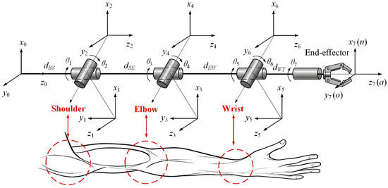
The seven-DOF humanoid manipulator consists of seven rotational joints. The first three joints, the middle joint, and the last three joints correspond to the shoulder, elbow, and wrist of the human arm, respectively. Both the shoulder joint and the wrist joint adopt a spherical wrist structure (the axes of the three joints intersect at a single point) (Figure 1).
Figure 1.
The structural diagram of the seven-DOF humanoid manipulator.
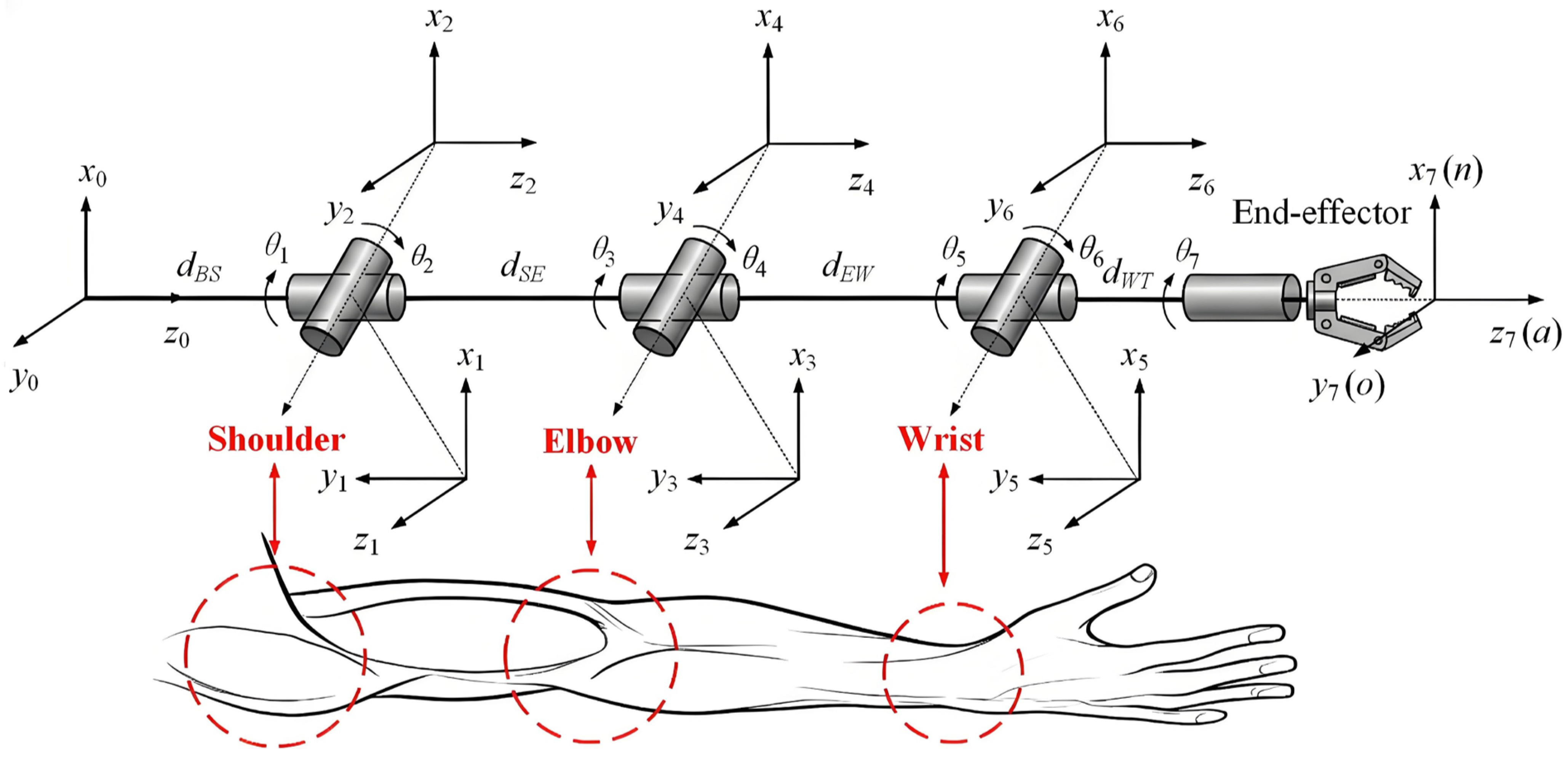
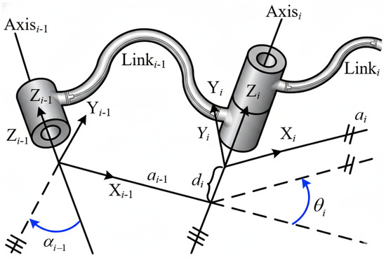
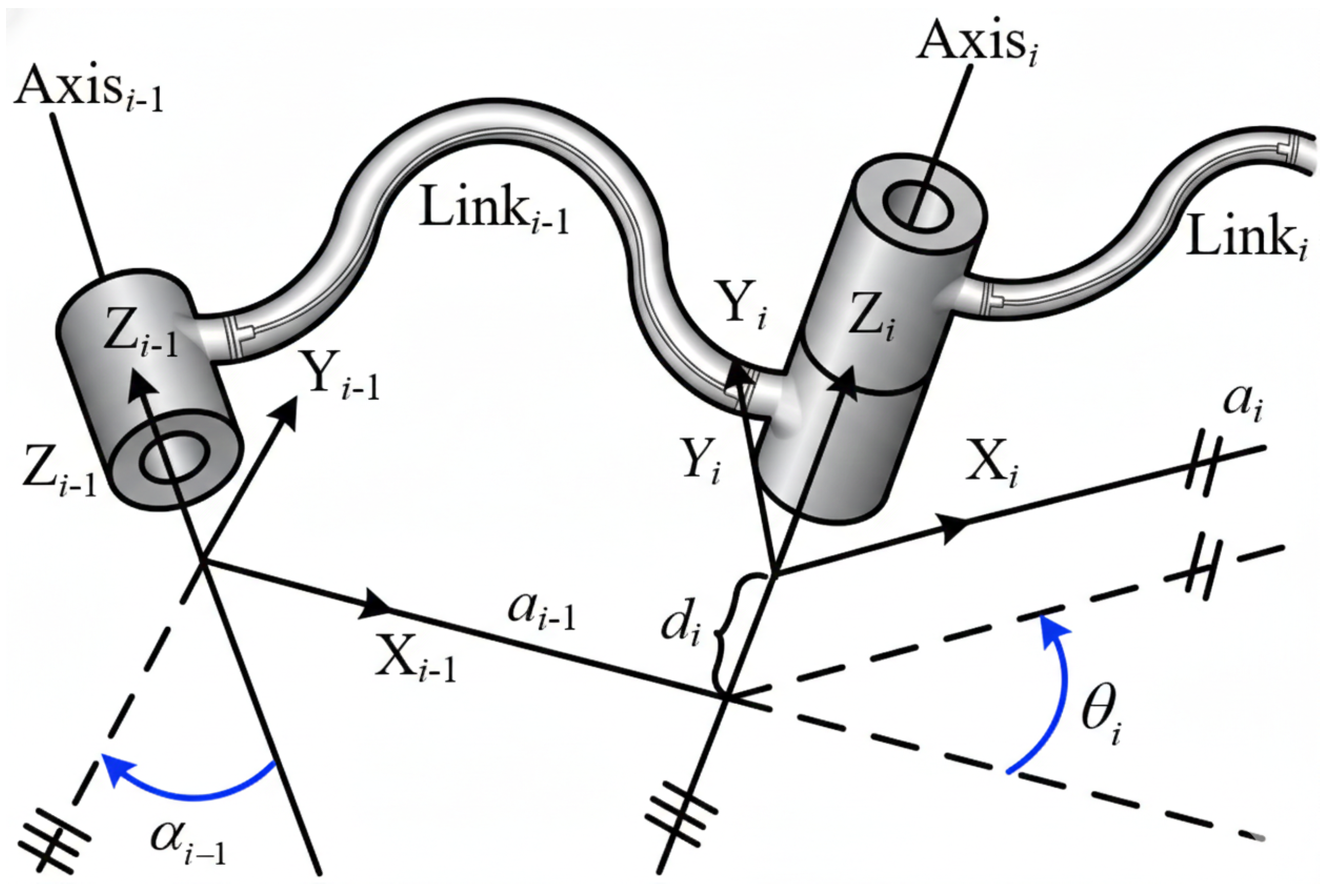
In order to describe the relationship between the joint angles of the manipulator and its pose (position and orientation), it is necessary to define the coordinate frames. First, the base coordinate frame is fixed to the ground. Then, the coordinate frames of each joint are defined based on the Denavit-Hartenberg (D-H) convention (Figure 2). Nominally, the origin of the i-th coordinate frame is placed on the (i + 1)-th joint axis, which is aligned with the z-axis. The x-axis is aligned with the normal vector of the i-th and (i + 1)-th joint axes. Given the directions of the x-axis and z-axis, the direction of the y-axis is determined using the right-hand rule.
Figure 2.
Schematic diagram of the local coordinate systems of the links based on the Denavit–Hartenberg modeling method.
Under the above definitions, the representation of the manipulator link parameters is shown in Table 1. It should be noted that due to the different initial poses of the manipulator, the link parameters obtained using the standard D-H modeling method are not unique.
Table 1.
Joint parameters of the seven-DOF humanoid manipulator based on standard D-H modeling method.
According to the standard D-H modeling method [27], the mathematical expression of the Cartesian transformation matrix of the j-th link coordinate frame with respect to the (j − 1)-th link coordinate frame is shown in Equation (1).
By determining the coordinate frames associated with each joint, the pose transformation matrix of the end-effector relative to the base frame can be derived [28]:
3. Self-Motion Parameters for Joint Decoupling
3.1. Arm-Angle Parameter
For a seven-degree-of-freedom redundant manipulator, the end-effector pose constraint typically provides only six independent constraints. Therefore, infinitely many feasible joint solutions may exist while satisfying a given end-effector pose. This redundancy is mainly reflected in the self-motion of the shoulder-elbow-wrist configuration, where the spatial swing of the elbow leads to a continuous family of solutions from a geometric perspective. To explicitly parameterize the redundancy and facilitate joint-space decoupling, an arm-angle parameter is introduced in this work.
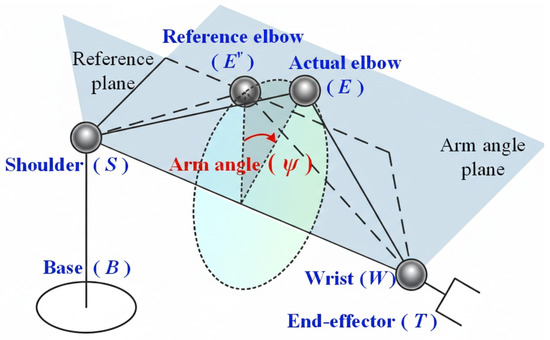
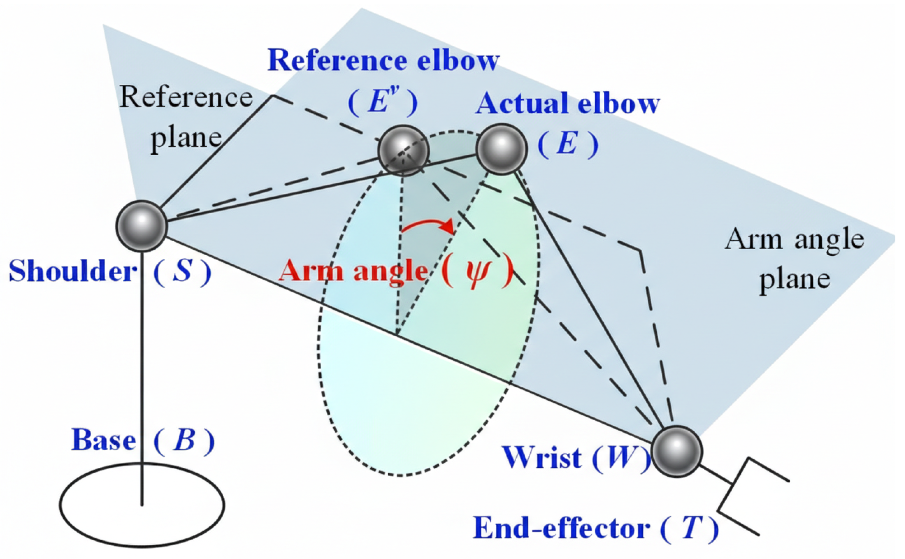
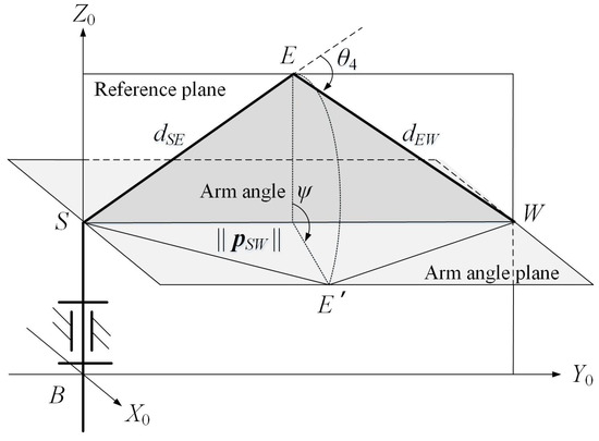
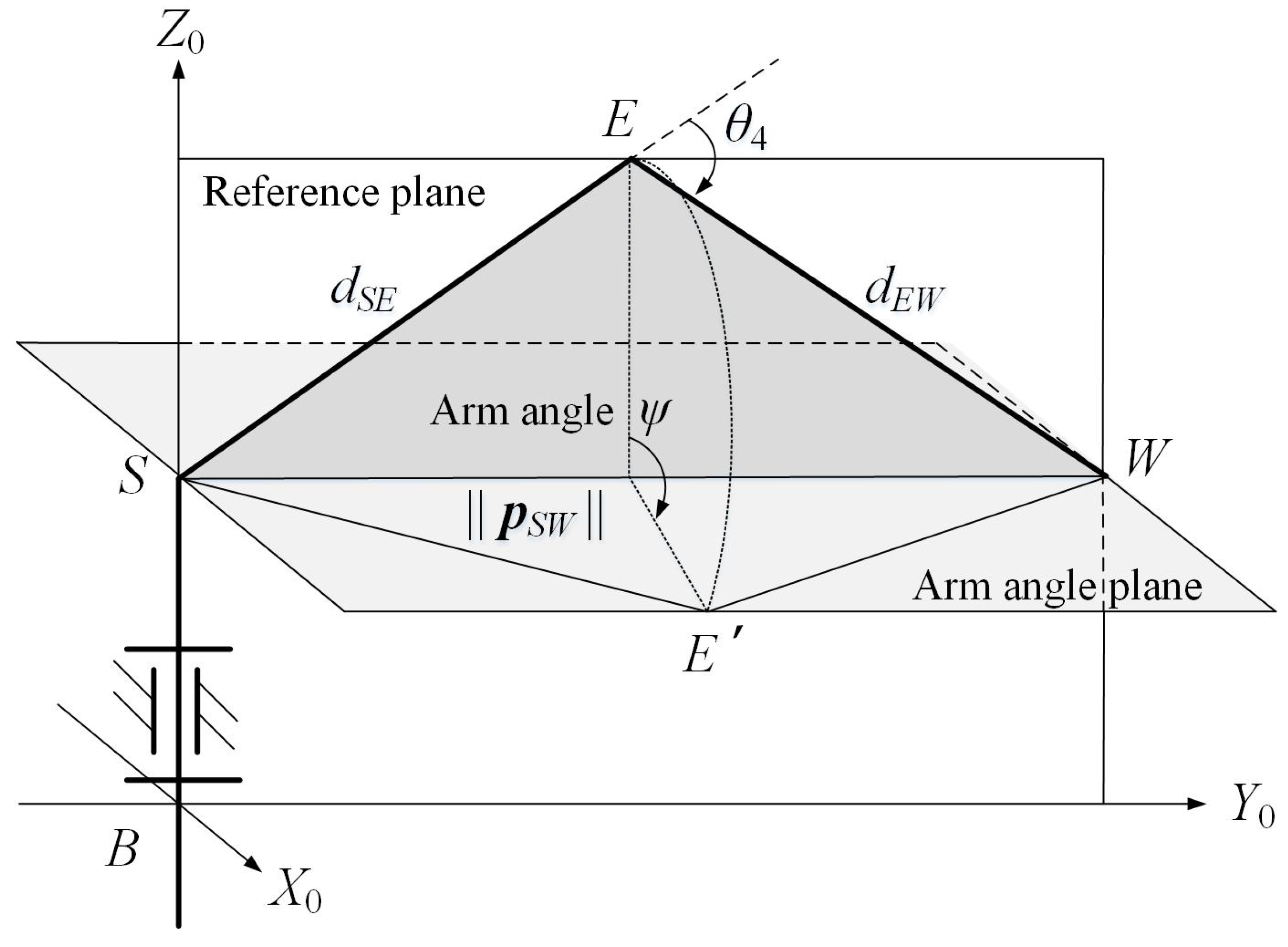
In this paper, the arm-angle parameter is introduced [29] to represent the uncertain motion of the elbow joint of a 7-DOF humanoid manipulator. The arm angle () is defined as the angle between the plane (SEW) consisting of the shoulder (S), elbow (E), and wrist (W) of the manipulator and the reference plane (SEvW) (Figure 3).
Figure 3.
Schematic diagram of the arm angle.
In theory, the reference plane can be chosen arbitrarily. For the convenience of subsequent inverse kinematics solutions, this paper defines the plane formed by the shoulder, elbow, and wrist of the manipulator when the third joint angle 3 = 0 as the reference plane. When the third joint is fixed, the 7-DOF redundant manipulator can be considered as a non-redundant manipulator. It can be proved that when all joints are in reachable states, the end-effector of the non-redundant manipulator can reach any specified pose within the workspace. In this case, if the pose of the end-effector is determined, the joint angles are also uniquely determined. Therefore, the reference plane obtained when the third joint is fixed is theoretically feasible.
3.2. Global Configuration Parameters
Although the arm angle parameterization reduces the redundant solution set to an analytical family indexed by the arm angle, inverse kinematics derivation and practical implementation still involve multiple solution branches due to inverse trigonometric operations and disconnected feasible arm-angle intervals caused by joint limits. Without a unified configuration description, branch selection can be ambiguous and configuration switching may occur, leading to discontinuities. To address these issues, global configuration parameters are introduced to represent the overall shoulder-elbow-wrist configuration, which facilitates branch determination in analytical IK derivation and improves the controllability and stability of configuration management.
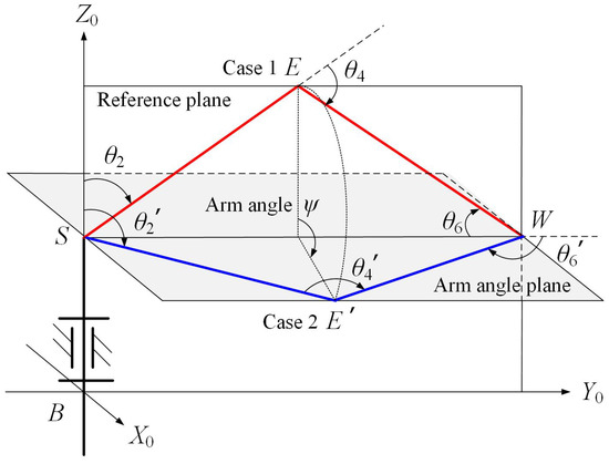
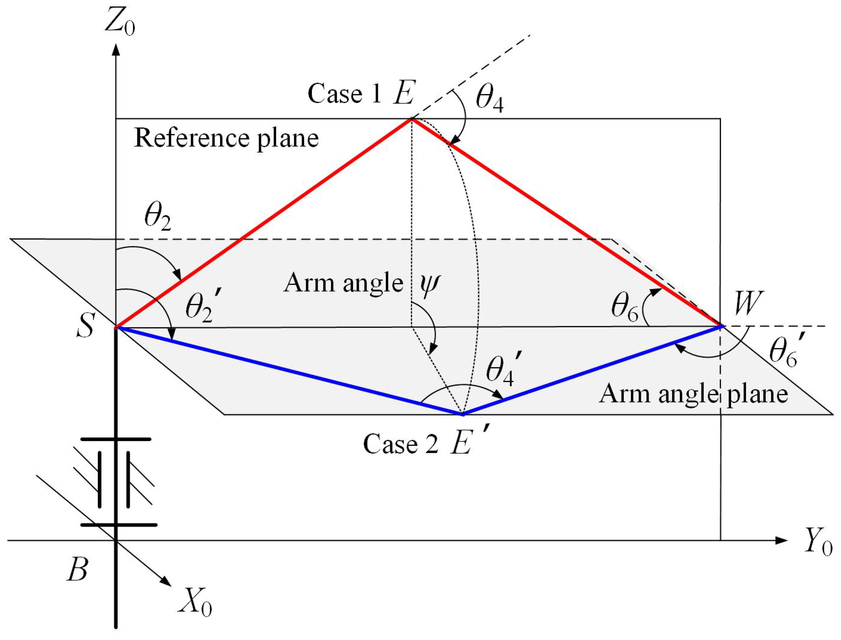
The global configuration parameters k are defined by three variables: 2, 4, and 6, which are used to represent the positions of the shoulder, elbow, and wrist of the manipulator during its motion (Figure 4). By determining the joint configurations of the manipulator at these positions, it becomes easier to determine the branches of the inverse kinematics solution in the subsequent inverse kinematics derivation process. The mathematical expression of k is given by Equation (3).
Figure 4.
Two sets of joint configurations under the control of global configuration parameters.
4. Inverse Kinematics Solution
4.1. Solving for the Elbow Joint Angle
To facilitate the derivation of analytical expressions for the joint angles, the pose matrix of the end-effector is defined as shown in Equation (4).
It is evident that the end-effector can reach the wrist position by translating a distance of in the opposite direction of . The corresponding relationship is given by Equation (5).
where represents the wrist position of the manipulator. Simplifying Equation (5) gives Equation (6):
Given that the position of the manipulator shoulder in Cartesian space is , and based on , the vector expression from the shoulder to the wrist of the manipulator can be obtained, which is:
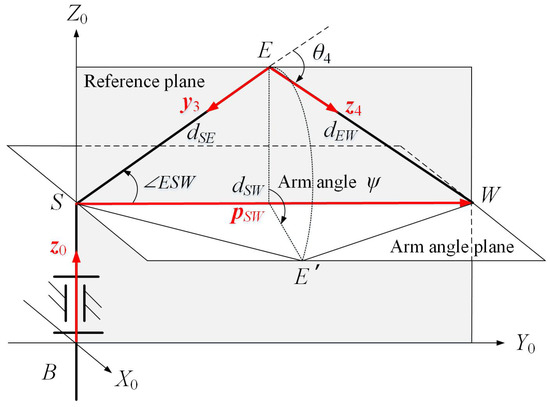
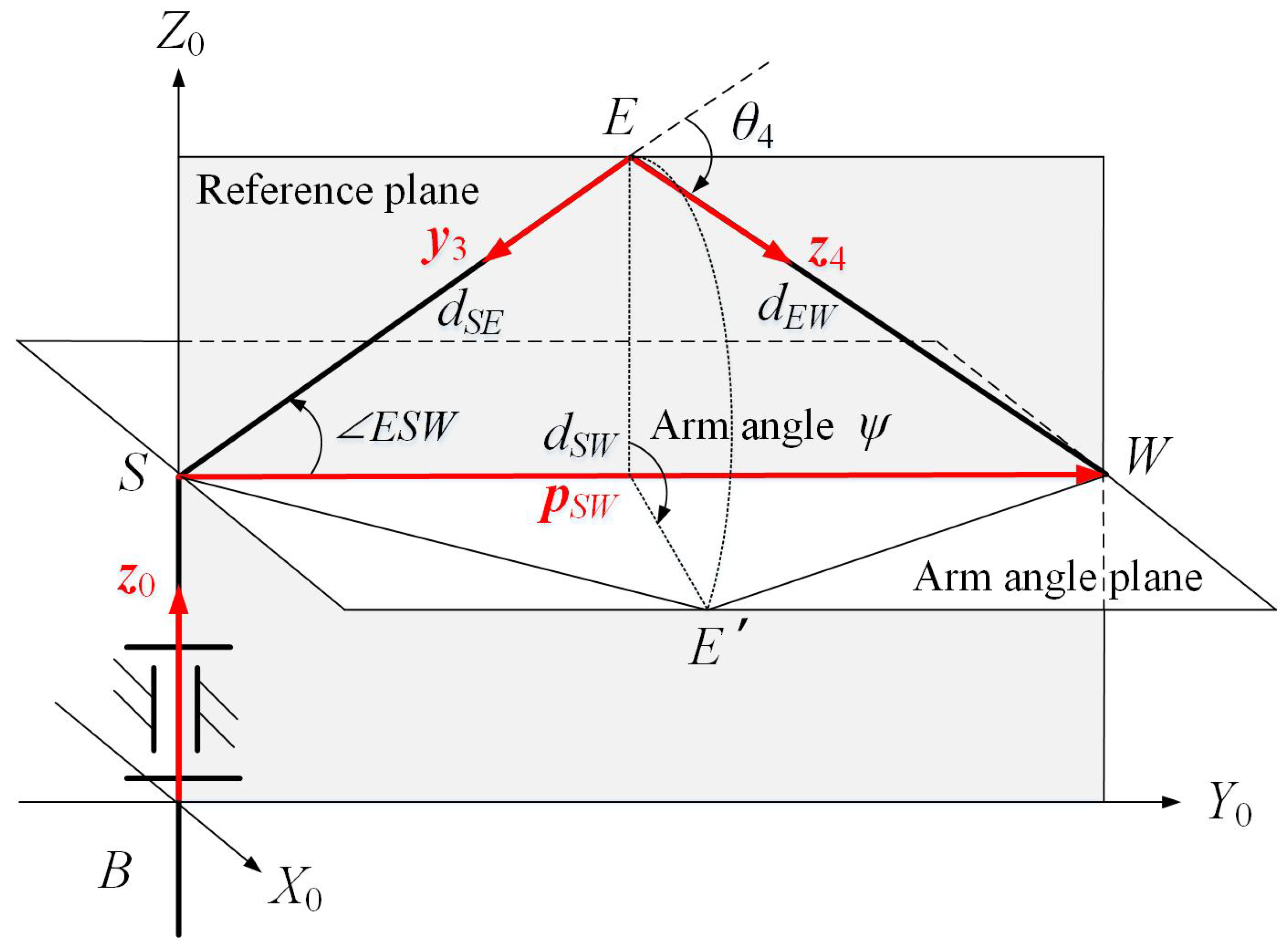
According to the geometric relationship of triangle SEW within the reference plane in Figure 5, and by combining the global configuration parameter 4, the expression for ∠SEW can be derived. Then, by analyzing the geometric relationship associated with the elbow joint angle 4 in Figure 5, the mathematical expression for 4 can be obtained, which is:
Figure 5.
Schematic diagram of the elbow joint angle.
4.2. Determination of Rotation Matrix in Reference Plane
To solve for the shoulder joint angle, the Rodrigues formula is introduced, and its mathematical expression is given by Equation (9).
where I represents the identity matrix; represents the rotational joint angle; represents the skew-symmetric matrix of vector k; and represents the rotation matrix corresponding to a rotation of angle about the axis .
Figure 6 shows the schematic diagram of local coordinate frames within the reference plane. Based on the planar triangular structure formed by the manipulator shoulder (S), elbow (E), and wrist (W) in Figure 6, along with the local coordinate frames obtained using the standard DH modeling method, Equation (10) can be derived.
Figure 6.
Schematic diagram of the manipulator local coordinate system.
When the arm angle is set to = 0, the rotation matrix of the first three joints can be written as:
It is evident that . By substituting the mathematical expression of into Equation (10), the mathematical expression for can be obtained:
According to Figure 6, it is evident that is the unit vector in the opposite direction of vector , rotated by the angle ∠ESW around the normal vector of the reference plane formed by vector and vector . According to the Rodrigues formula shown in Equation (9) and the right-hand rule, the mathematical expression for the rotation matrix corresponding to the rotation by angle ∠ESW around the normal vector of the reference plane formed by vector and vector is obtained, which is:
Based on Equation (13) and the cross product formula, the mathematical expressions for and are obtained as follows:
4.3. Solving for Shoulder Joint Angles
When the manipulator elbow undergoes self-motion, the arm angle changes, which results in corresponding changes in the rotation matrix formed by the first three joint angles, namely:
where represents the unit vector of . By substituting the Rodrigues formula in Equation (9), Equations (16) and (17) can be obtained.
Based on Equation (1), the expression for the rotation matrix of the first three joint angles can be derived. Combining with Equation (17), the relationship between the arm angle and shoulder joint angles can be expressed as follows:
where , , and represent the elements in the i-th row and j-th column of matrices , , and , respectively. Based on Equations (18)–(20), and combining the global configuration parameter , the analytical expressions for , , and can be obtained, which are:
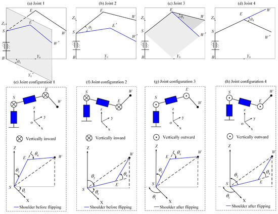
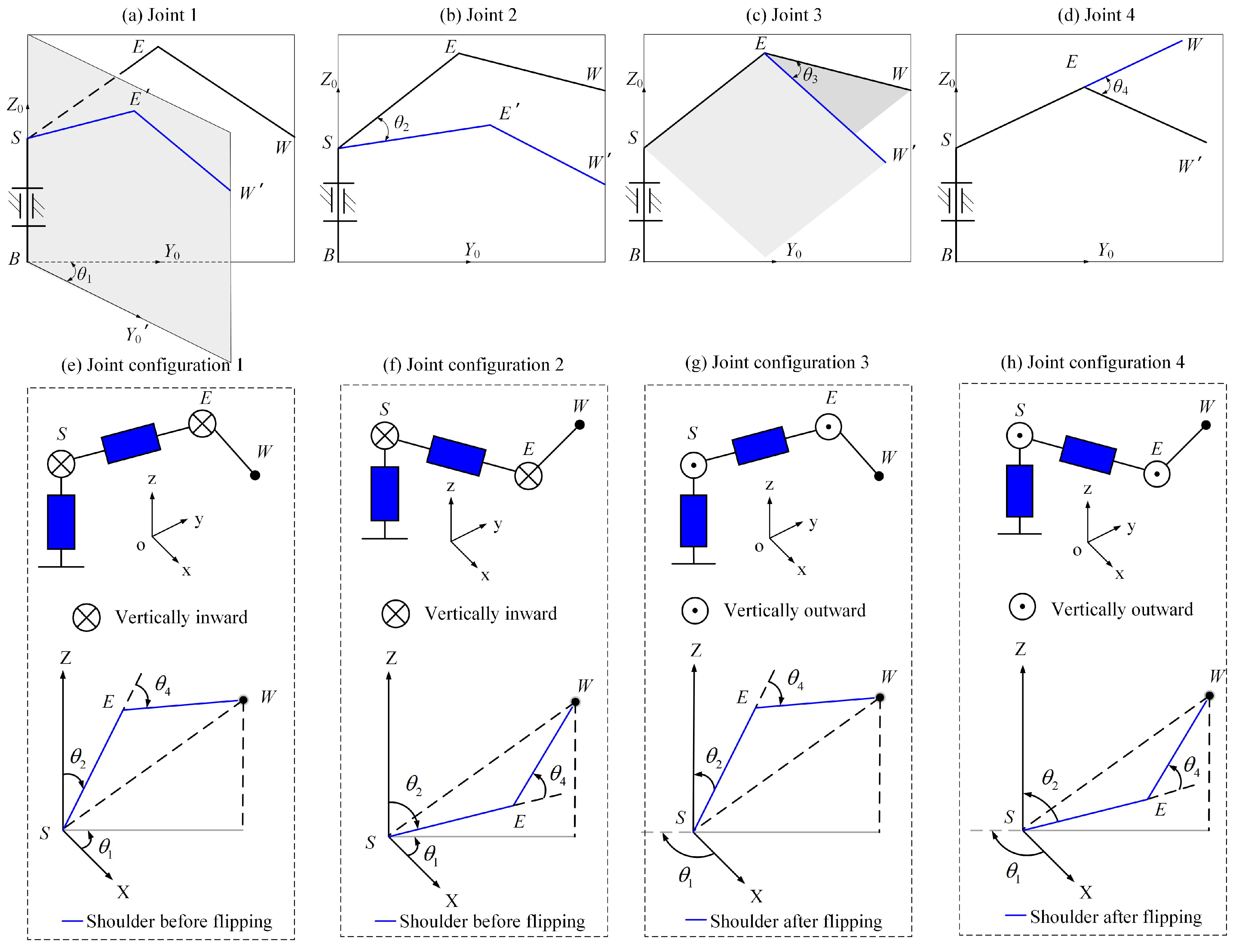
Figure 7 shows the shoulder joint angles, elbow joint angle, and the corresponding four joint configurations when the shoulder and wrist of the manipulator are fixed.
Figure 7.
Shoulder joint angles, elbow joint angle and four joint configurations.
4.4. Solving for Wrist Joint Angles
For the wrist joint angles 5, 6, and 7, the mathematical expression for the rotation matrix of the last three joint angles can similarly be derived from Equation (1). By expressing the transformation from the end-effector frame to the base frame, Equation (24) can be obtained.
Based on Equation (25), the relationship expressions between the arm angle and wrist joint angles can be obtained, which are:
Based on Equations (26)–(28), and combining the global configuration parameter , the analytical expressions for , , and can be obtained, which are:
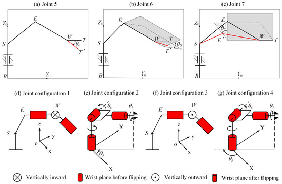
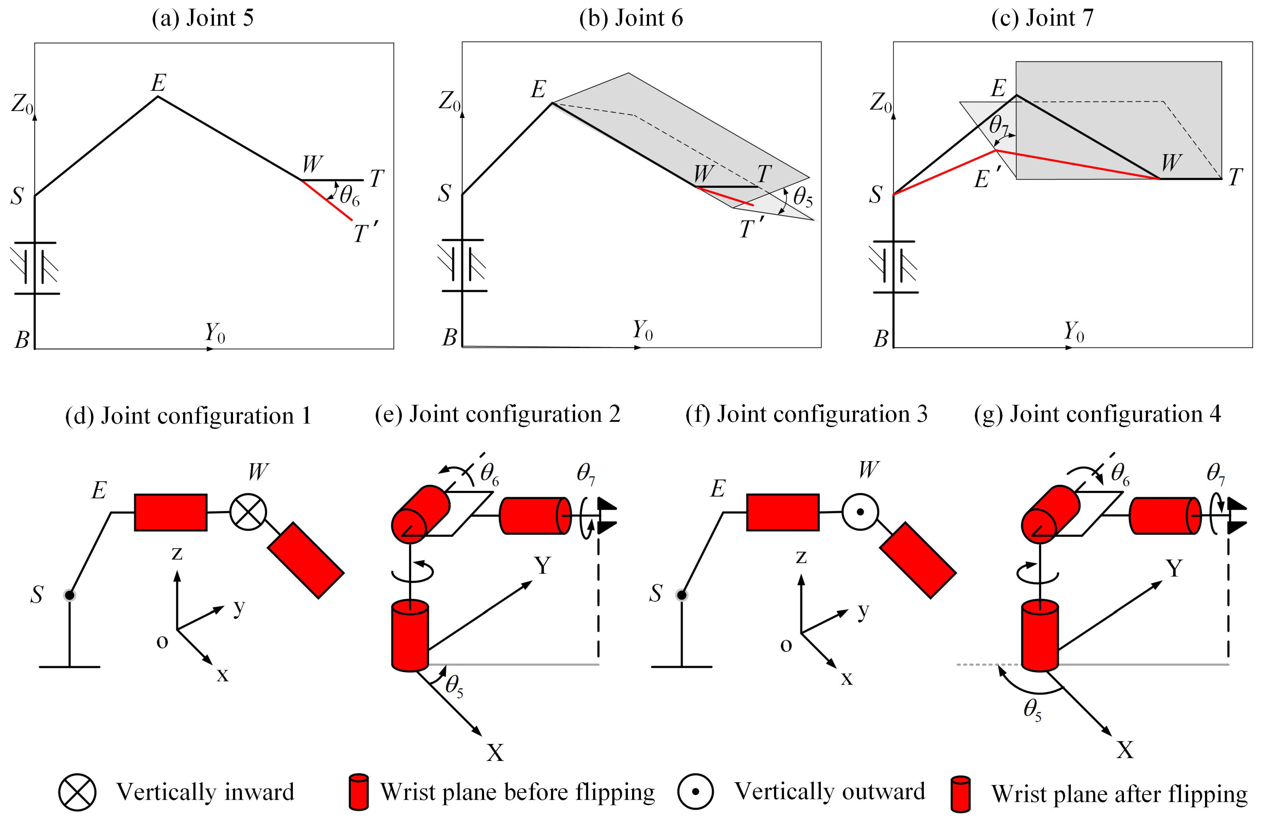
Figure 8 shows the wrist joint angles, and the corresponding four joint configurations formed by the wrist joint angles.
Figure 8.
Wrist joint angles and four joint configurations.
5. Determination of Feasible Arm-Angle Intervals
5.1. Analysis of Joint Angle Analytical Expressions
Since analytical expressions for shoulder joint angles and wrist joint angles are derived based on arm angle, determining the feasible arm-angle intervals is essential for obtaining valid inverse kinematics solutions. At the same time, by reducing the feasible arm-angle intervals, the number of solutions that need to be evaluated in the subsequent arm angle optimization process can be reduced, thus lowering computational complexity and improving solution efficiency.
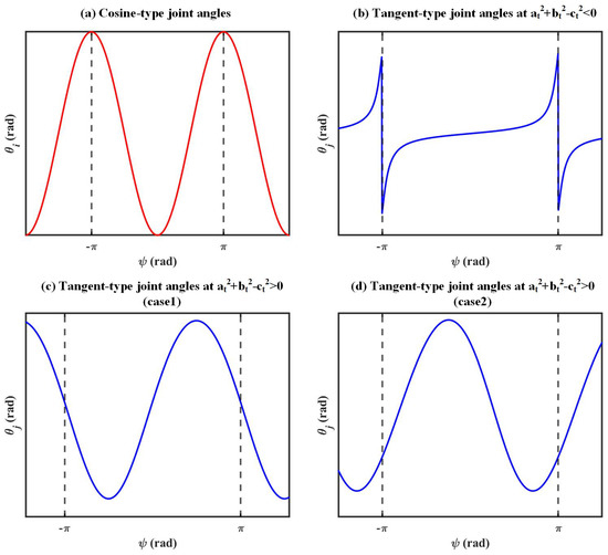
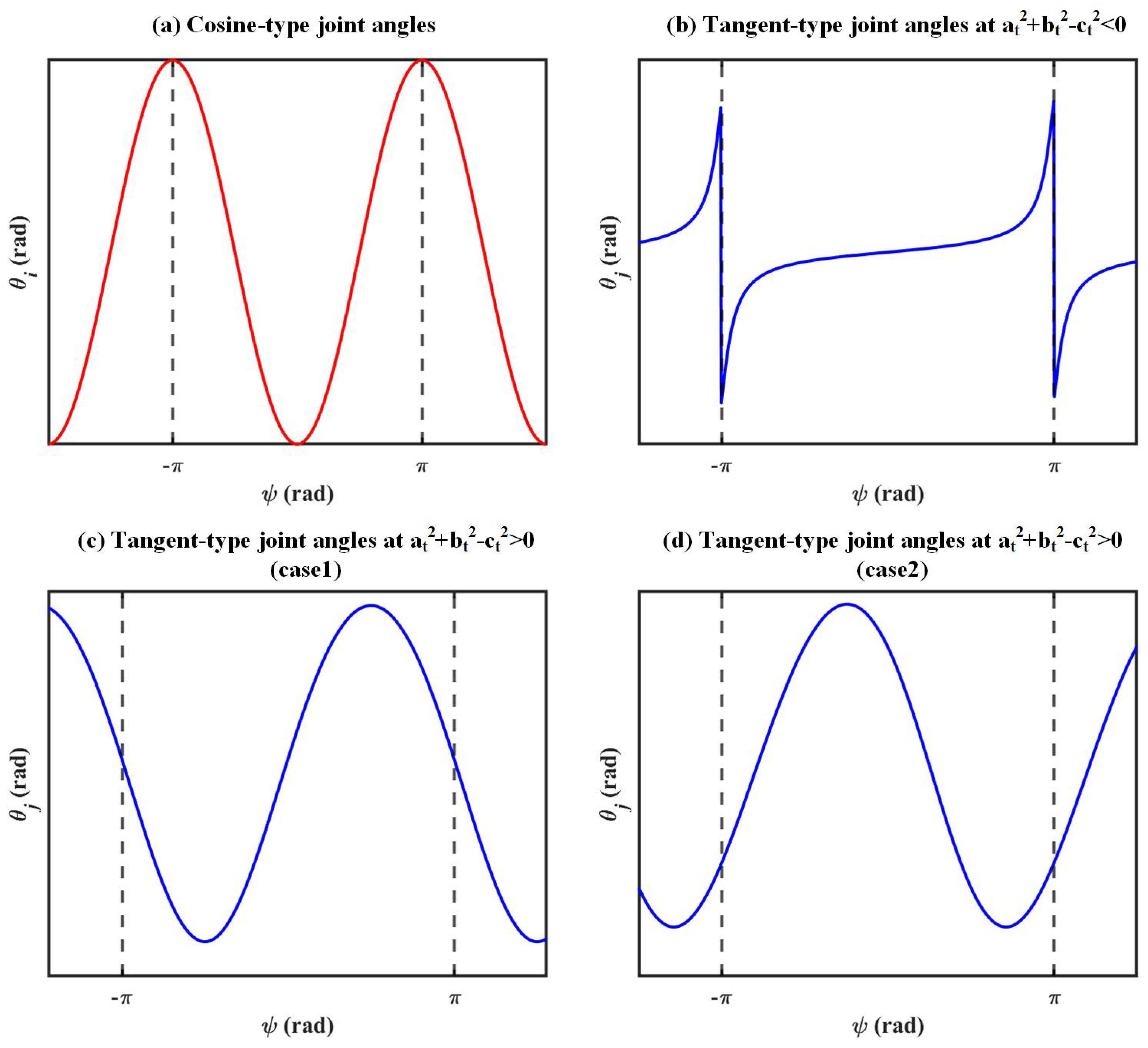
By analyzing the analytical expressions of shoulder joint angles and wrist joint angles, it can be observed that the relationship between shoulder joint angles, wrist joint angles, and arm angle can be divided into the following two types (Figure 9):
Figure 9.
Variation curves of different types of joint angles.
Equation (32) shows that the joint angles corresponding to and are cosine-type joint angles. Equation (33) shows that the joint angles corresponding to , , , and are tangent-type joint angles. Below, the feasible arm-angle intervals corresponding to these two types of joint angles will be discussed.
5.2. Determination of Feasible Arm-Angle Intervals for Cosine-Type Joint Angles
Let the left-hand side of Equation (34) be and the right-hand side be . Therefore, the problem of solving the feasible arm-angle intervals for cosine-type joint angles can be transformed into finding the range of when the function has a range of [, ], given . In this case, the corresponding feasible arm-angle intervals are shown in Table 2.
Table 2.
Feasible arm-angle intervals corresponding to cosine-type joint angles.
5.3. Determination of Feasible Arm-Angle Intervals for Tangent-Type Joint Angles
Tangent-type joint angles include , , , and . By differentiating both sides of Equation (33) with respect to arm angle , Equation (35) can be obtained.
By setting the derivative on the left-hand side of Equation (35) equal to zero, the corresponding arm angle can be obtained, which represents the stationary point of the j-th joint angle. The arm angle values corresponding to the upper and lower limits of the j-th joint angle are defined as follows:
Based on Equation (35), , , and can be obtained. By evaluating the value of , can be classified into monotonic and periodic types. The corresponding feasible arm-angle intervals will be discussed separately below.
When , the joint angle is monotonic. Analyzing Equation (35), it can be seen that when , Equation (35) is always greater than 0, meaning that increases monotonically with arm angle ; when , Equation (35) is always less than 0, meaning that decreases monotonically with arm angle ; and due to the special nature of the tangent function, may have jump discontinuities. When the arm angle is within the range [−, ], if the joint angle reaches the boundary value, a jump will occur. In this case, the feasible arm-angle intervals are shown in Table 3.
Table 3.
Feasible arm-angle intervals corresponding to tangent-type joint angles when .
When , the joint angle is periodic. Analyzing Equation (35), it can be seen that in this case, the joint angle has two stationary points, one where the joint angle reaches the minimum value , and the other where the joint angle reaches the maximum value . Let the arm angles corresponding to the minimum and maximum values be and , respectively, as shown in the following expression:
Based on Equation (35), it is clear that when the arm angle is determined, the maximum and minimum values of are as follows:
It should be noted that the boundary value of the joint angle when the arm angle is within the range [−, ] is as shown in Equation (43).
The feasible arm-angle intervals of are obtained by enforcing the joint limit constraints. Specifically, for each , the corresponding joint-angle bounds and are compared with the prescribed joint limits and , together with the boundary value , to determine the admissible values of . The resulting feasible arm-angle intervals of are summarized in Table 4.
Table 4.
Feasible arm-angle intervals corresponding to tangent-type joint angles when .
6. Optimization of Arm Angle
6.1. Problem Description
After deriving the analytical expressions of the joint angles with respect to the arm angle, the next step is to optimize the arm angle within the feasible arm-angle domain. For a redundant manipulator, the inverse kinematics problem can be formulated as determining the optimal joint configuration in joint space under six equality constraints and other inequality constraints. A commonly used optimization approach for solving inverse kinematics of manipulators is to treat all joint angles as variables and find an inverse kinematics solution that satisfies the constraint conditions by minimizing a target function, that is:
where f represents the objective function; represents the joint-angle vector; and and represent the lower and upper joint-angle limits, respectively.
When solving the inverse kinematics of a redundant manipulator based on the arm angle, analytical expressions for the joint angles as functions of the arm angle are derived; thus, the unknown variable shifts from the joint angles to the arm angle. Accordingly, the objective function changes from to . The inverse kinematics problem can therefore be formulated as Equation (45).
where represents the arm angle, and and represent the lower and upper bounds of , respectively.
Equation (45) shows that introducing the arm angle transforms the inverse kinematics of a redundant manipulator into a one-dimensional optimization problem. Compared with multi-dimensional optimization, one-dimensional optimization reduces the number of decision variables, thereby lowering computational complexity. Moreover, one-dimensional optimization algorithms generally achieve higher search efficiency than their multi-dimensional counterparts.
6.2. Objective Function Based on Joint Limit Avoidance Criterion
When manipulator joint angles approach their limits, problems such as reduced mobility, path-planning failure, increased control error, and accelerated wear or damage of mechanical components may occur. Therefore, joint-limit avoidance is desirable. Because joint limits can differ across joints, the joint angles are normalized to quantify the proximity of each joint to its limits. The normalization is given in Equation (46).
where represents the normalized result corresponding to the i-th joint angle ; and and represent the lower and upper limits of the i-th joint angle, respectively. In Equation (46), the value range of is [−1, 1]. After normalizing the joint angles, the closer is to 1, the closer the i-th joint angle is to its upper limit. Conversely, the closer is to −1, the closer the i-th joint angle is to its lower limit. From the perspective of avoiding joint limits, it is preferable for each joint to stay as far away from its limits as possible.
To prevent manipulator joints from approaching their limits while accounting for end-effector pose error, this section formulates an objective function based on a joint-limit avoidance criterion. The resulting expression is given in Equation (47).
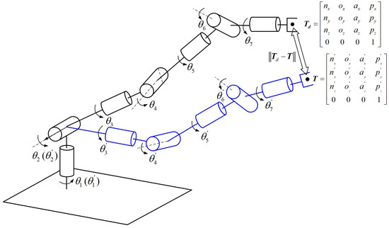
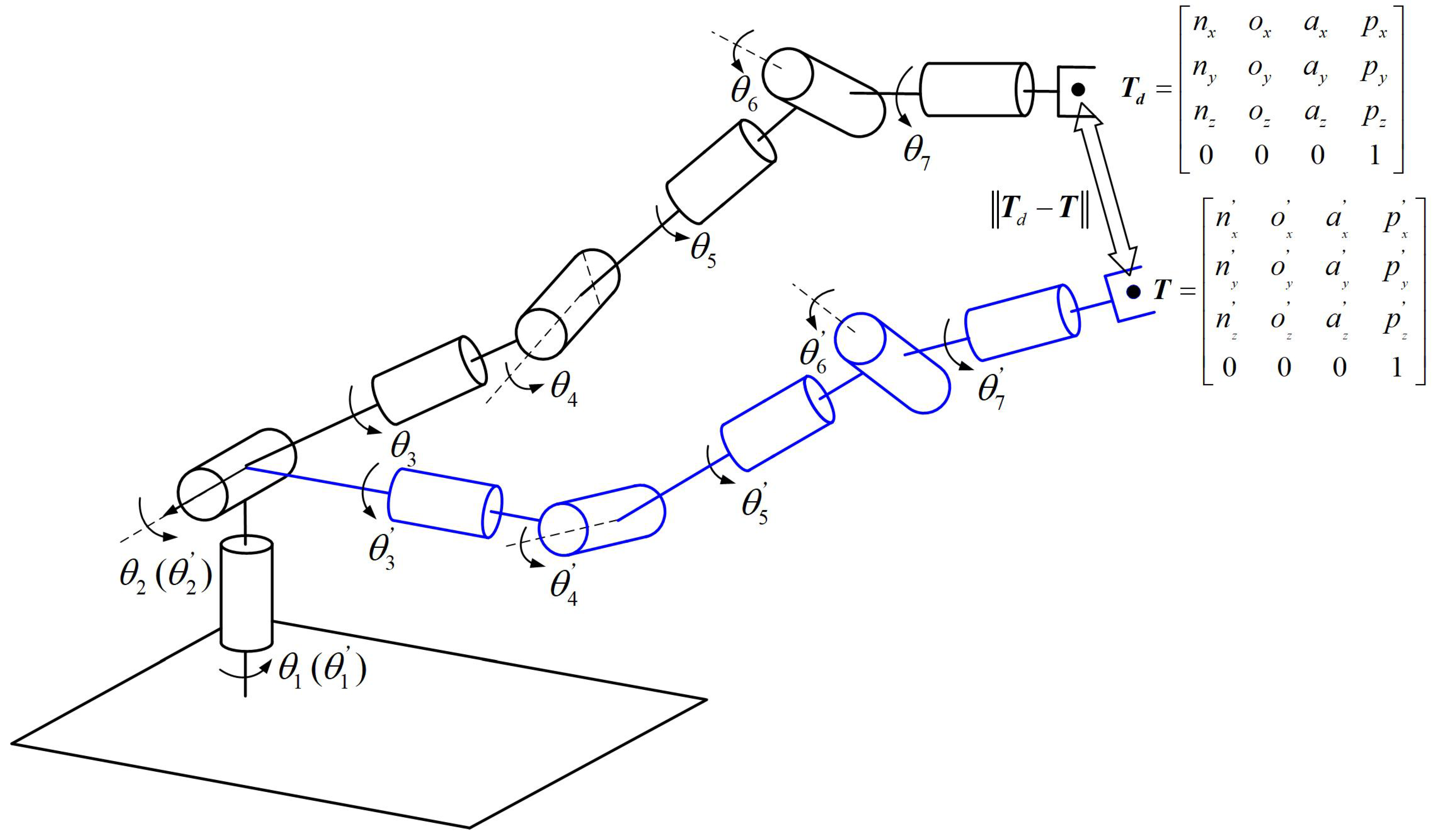
where and represent given constant values, with . and represent the desired and actual pose matrices of the end-effector, respectively (Figure 10); and represent the normalized joint angle vector and the center vector of the joint limits composed of zeros, respectively.
Figure 10.
Pose error diagram of the 7-DOF humanoid manipulator.
In Equation (47), a larger value of indicates a larger end-effector pose error and a joint configuration that shifts from the mid-range toward the joint limits. Conversely, a smaller value of implies a smaller pose error and a configuration closer to the centers of the joint ranges, thereby maintaining a greater margin from the limits. Minimizing therefore helps avoid joint-limit violations while preserving end-effector pose accuracy.
6.3. Derivative-Free One-Dimensional Interval Search Algorithm
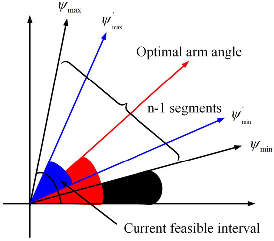
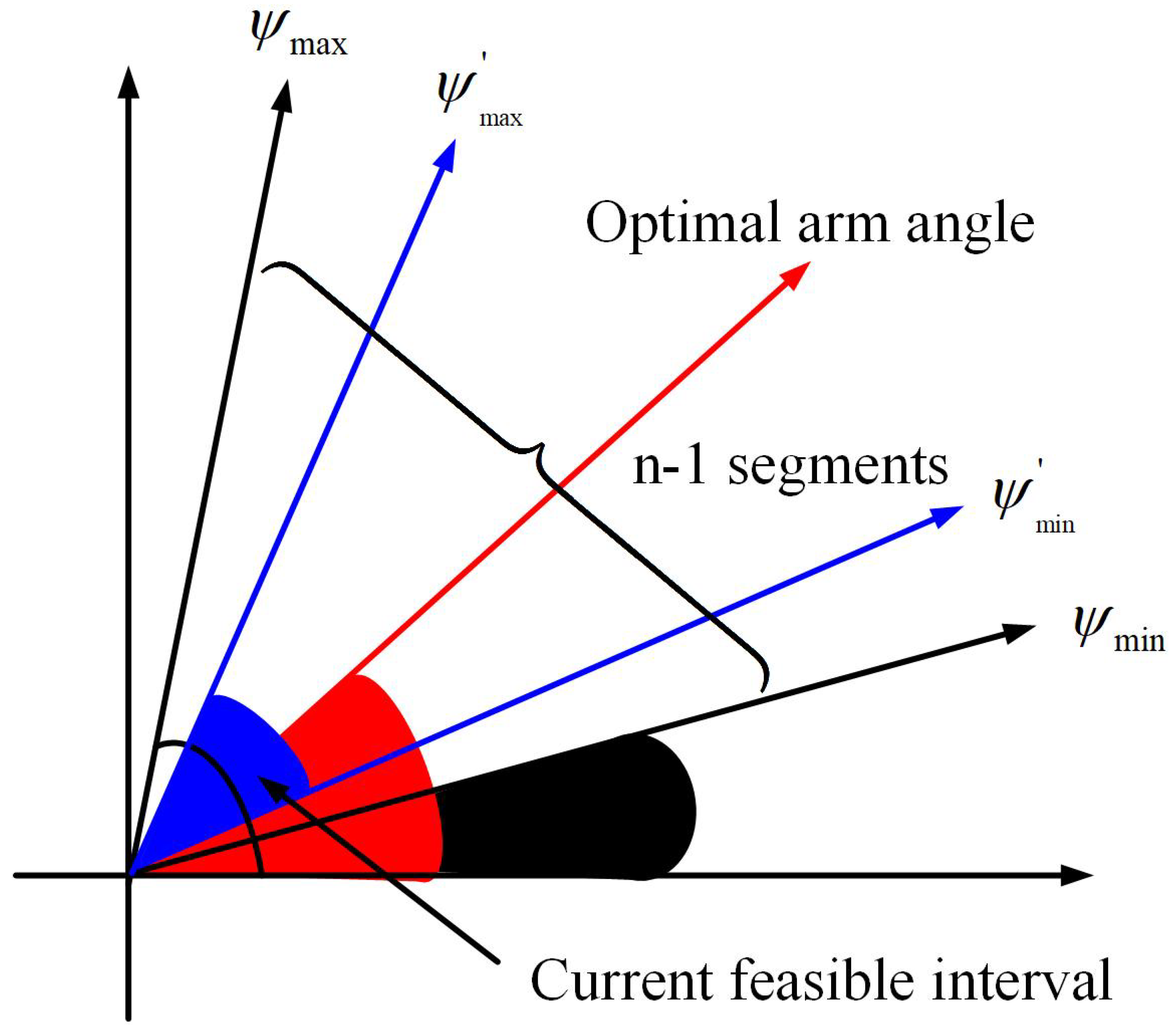
This section presents a derivative-free one-dimensional interval search algorithm for determining the optimal arm angle within a known feasible arm-angle interval. The algorithm is based on an exhaustive-search strategy. The algorithm iteratively contracts the search interval to efficiently locate the optimum of the objective function. Specifically, at each iteration, the feasible interval of is partitioned into subintervals, yielding n boundary points. The objective function is evaluated at these points, and the point with the best value is selected (Figure 11). The search interval is then reduced around the selected point, and the procedure is repeated until the interval width falls within a prescribed tolerance. The search performance mainly depends on the update of and its lower and upper bounds, which is given in Equation (48).
where represents the current arm angle, and and represent its current lower and upper bounds, respectively. The parameter specifies that the feasible interval is divided into n equal parts, and represents the index of the selected subinterval among the n divisions. Based on this update rule for , the corresponding update rules for the optimal arm angle and the optimal objective-function value are given in Equation (49).
where represents the current best arm angle, represents the corresponding objective-function value, and is a constant. The update rules for the lower and upper bounds of the arm angle are given in Equation (50) and Equation (51), respectively.
Figure 11.
Diagram of the optimal arm angle search.
During the arm-angle search, joint-limit constraints may cause the candidate optimal arm angle to lie outside the feasible range. In this case, the optimal arm angle is projected onto the feasible interval by selecting the nearest boundary value. The pseudocode of the proposed one-dimensional arm-angle search algorithm is provided in Algorithm 1.
| Algorithm 1 Derivative-Free One-Dimensional Interval Search Algorithm |
|
7. Simulation and Discussion
7.1. Determination of Feasible Arm-Angle Interval Under Specified Pose Conditions
This section aims to determine the multi-segment feasible arm-angle intervals for a known end-effector position and orientation, thereby defining the effective elbow motion range of the 7-DOF redundant manipulator. All simulations and experiments in Section 7 were conducted on a computer equipped with an Intel(R) Core(TM) i9-14900HX CPU and 16 GB of RAM, using MATLAB 2023. The link parameters are given as , , , and .
The desired end-effector position vector and orientation matrix are given below.
For the current end-effector pose, the feasible arm-angle intervals associated with the seven joints are computed using the method described in Section 6. The results are summarized in Table 5.
Table 5.
Feasible arm-angle interval corresponding to joint limits.
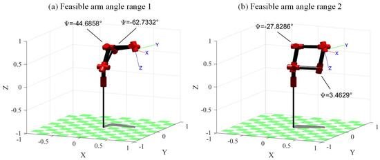
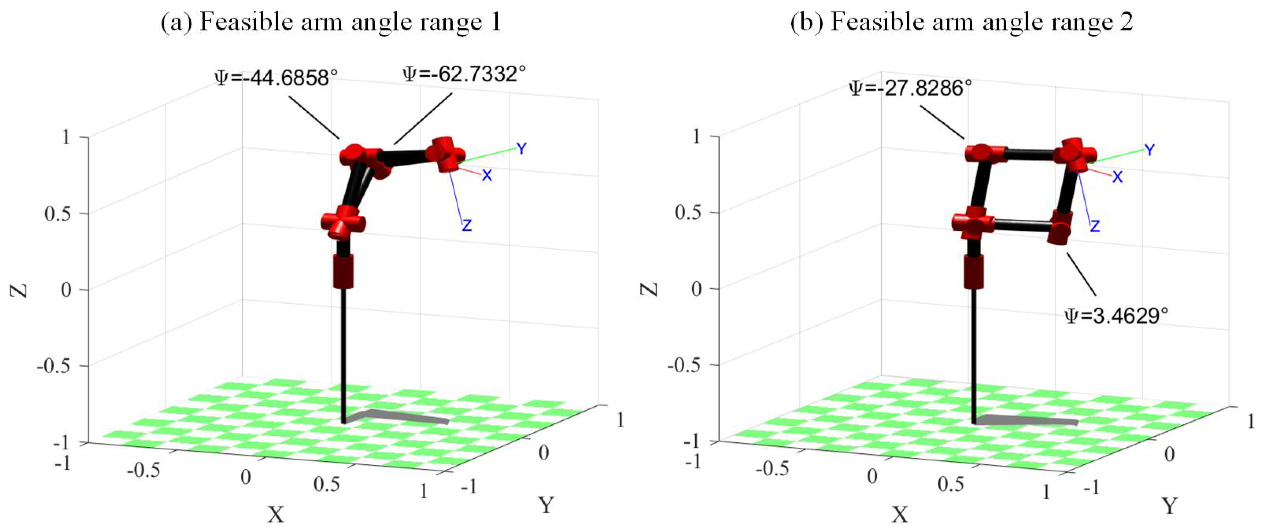
Given the arm-angle domain , the feasible arm-angle domain is obtained by intersecting the joint-specific feasible arm-angle intervals with this domain. The resulting feasible arm-angle domain is .
Based on the feasible arm-angle domain, the actual elbow motion range of the manipulator is obtained (Figure 12). As shown in Figure 12, the first joint configuration corresponds to , whereas the second joint configuration corresponds to . Notably, the feasible arm-angle domain comprises two disjoint intervals. For numerical or Jacobian-based approaches, identifying all globally separated feasible regions is often challenging. In contrast, the method proposed in this paper provides theoretically exact region boundaries.
Figure 12.
Actual elbow motion range under the feasible arm-angle intervals.
7.2. Cartesian Trajectory Tracking Simulation
This section takes a 7-DOF humanoid manipulator as the research object and performs Cartesian trajectory tracking simulation for a circular trajectory to verify the feasibility of the proposed method. The specific link parameters of the manipulator are given as: , , , and . Table 6 shows the limits of the joint angles for the manipulator. The mathematical expression for the circular trajectory is given in Equation (54).
Table 6.
Joint limits of the 7-DOF humanoid manipulator.
To facilitate inverse kinematics solving, the roll angle along the x-axis, pitch angle along the y-axis, and yaw angle along the z-axis of the end-effector are specified as (rad).
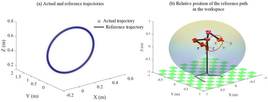
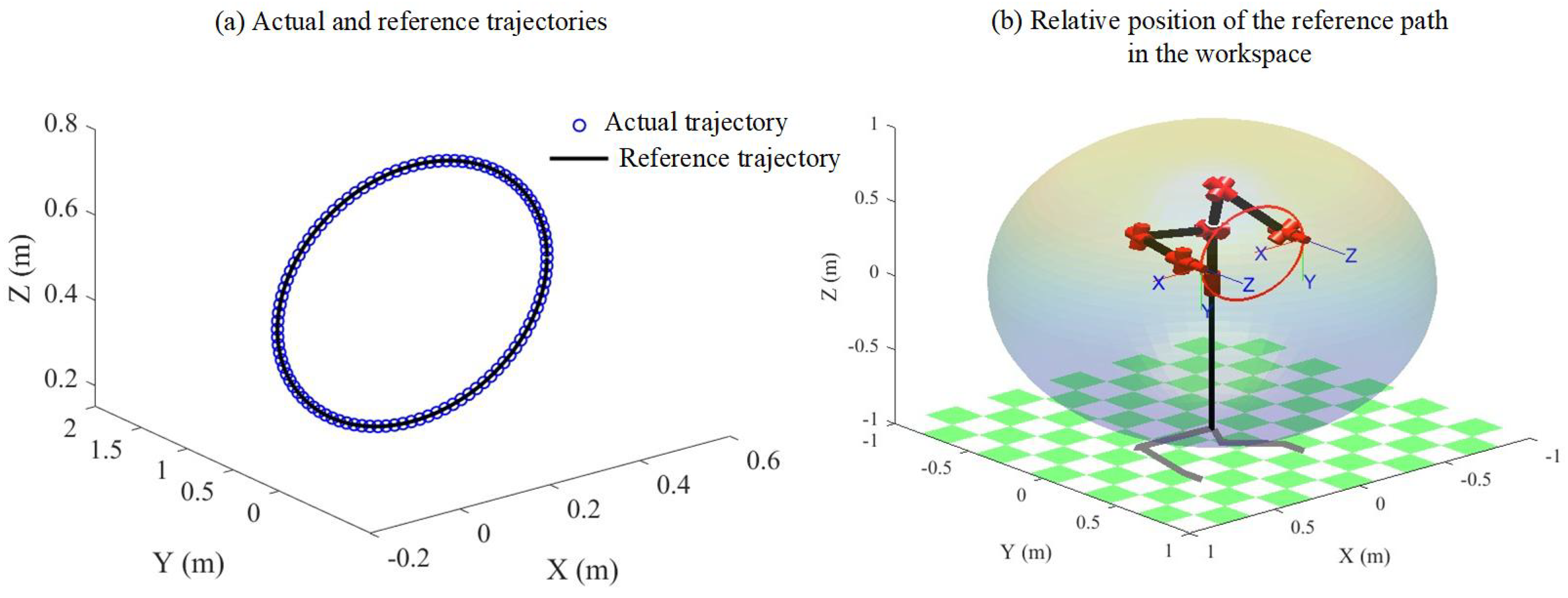
Figure 13a shows the actual trajectory and the reference trajectory. By comparing the overlap between the actual trajectory and the reference trajectory, it can be observed that the actual trajectory closely matches the reference trajectory.
Figure 13.
Actual trajectory, reference trajectory and the relative position of the reference trajectory in the workspace.
Figure 13b shows the relative position of the reference path in Cartesian space within the manipulator workspace. The results in Figure 13b indicate that the reference path lies within the manipulator workspace, and the end-effector can reach both the starting and ending points of the path, confirming the feasibility of the reference path.
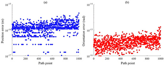
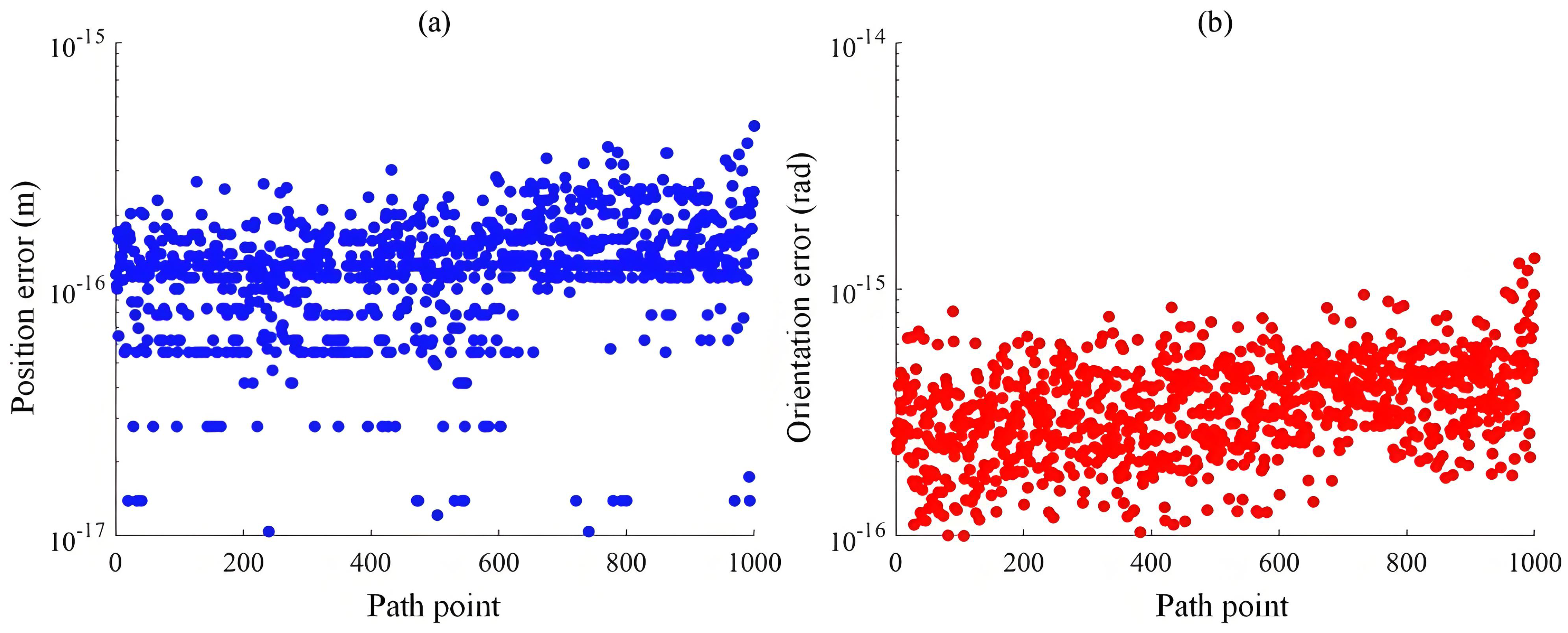
Figure 14a,b shows the position and orientation errors at the sampled path points during Cartesian trajectory tracking using the proposed method. The results in Figure 14 indicate that the position error obtained using the proposed method stabilizes between m and m, while the orientation error stabilizes between rad and rad.
Figure 14.
Pose error of Cartesian trajectory tracking.
Figure 15a–h shows the Simulink-based MATLAB simulation results for manipulator trajectory tracking. As shown in Figure 15, during circular trajectory tracking, the end-effector follows the desired path accurately, and no joint interference occurs throughout the motion. These results demonstrate that the proposed method yields reasonable joint configurations.
Figure 15.
Schematic diagram of circular trajectory tracking.
7.3. Cartesian Trajectory Tracking Experiment
This section takes a 7-DOF humanoid manipulator as the research object and performs Cartesian trajectory tracking experiment for a circular trajectory to verify the feasibility of the proposed method. The specific link parameters of the manipulator are given as: , , , and . Table 7 shows the limits of the joint angles for the manipulator. The mathematical expression for the circular trajectory is given in Equation (55).
Table 7.
Joint limits of the 7-DOF humanoid manipulator.
To facilitate inverse kinematics solving, the direction of the end-effector is fixed at each path point. The mathematical expression for orientation matrix R is given in Equation (56).
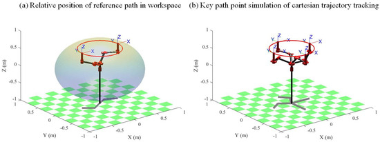
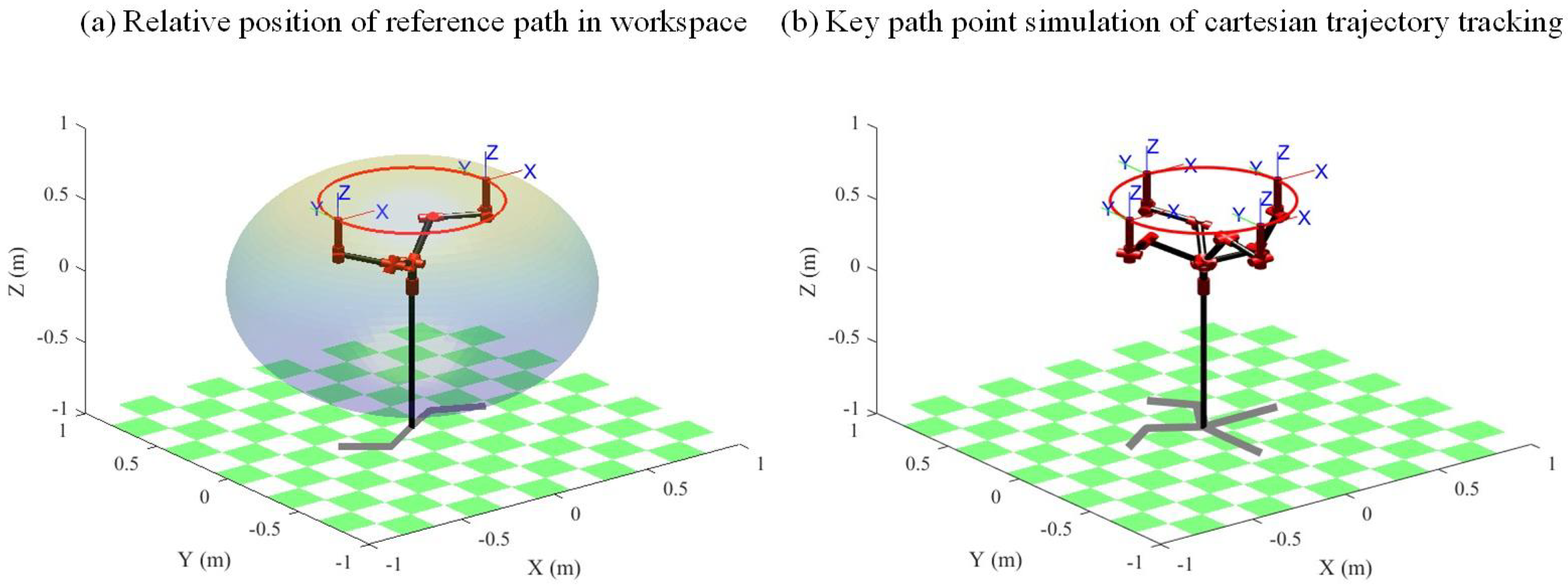
Figure 16 illustrates the Cartesian reference trajectory within the manipulator workspace and the simulated tracking results at several key path points. As shown in Figure 16, the reference trajectory lies entirely within the workspace, confirming its feasibility. In addition, the proposed inverse kinematics method generates valid joint configurations for the key path points, further demonstrating the feasibility of the method.
Figure 16.
Simulation of the relative position of the Cartesian trajectory and joint path points.
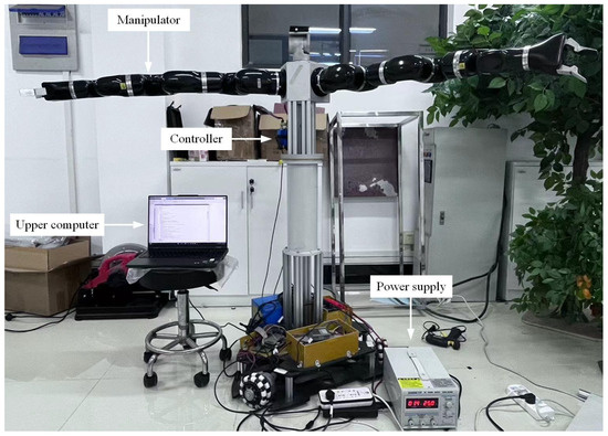
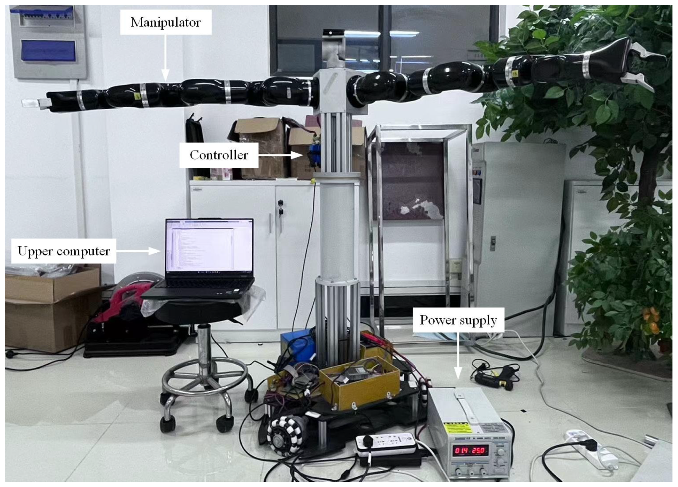
Figure 17 shows the experimental platform, which comprises four components: the manipulator, controller, upper computer, and power supply. Based on this platform, the experimental procedure is as follows:
Figure 17.
Experiment platform.
- Power on the system. Launch MRJScope on the upper computer, click Scan, and reset the zero positions of the seven joints after the joint information is displayed.
- Run the inverse kinematics algorithm in MATLAB on the upper computer to compute the joint solutions for the discrete path points.
- Enter the computed joint solutions into the Offset settings in MRJScope. The manipulator then executes the trajectory under controller command.
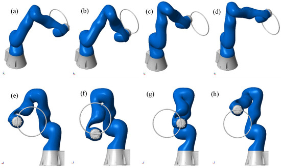
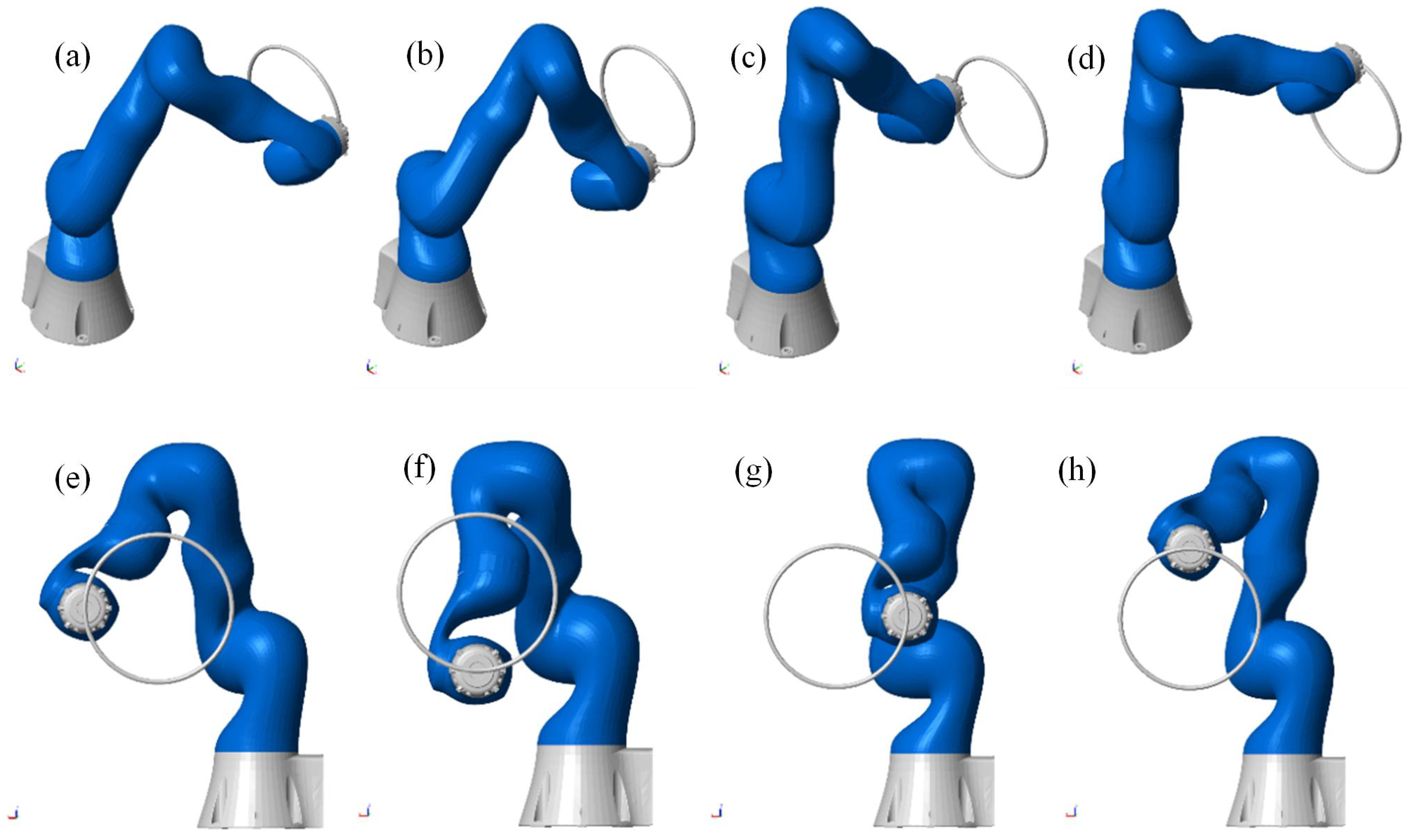
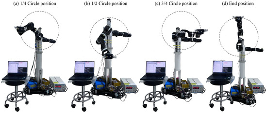
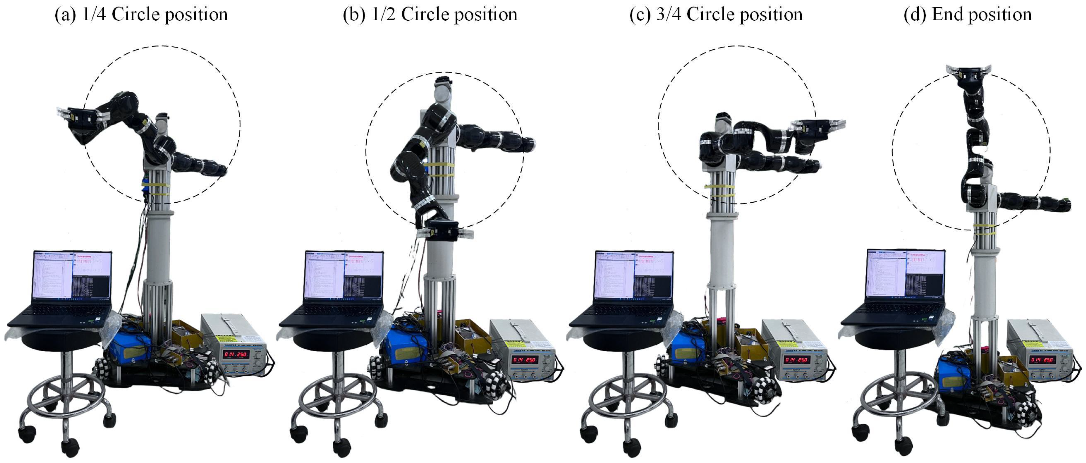
Figure 18 shows the four joint configurations corresponding to the four key path points in the trajectory-tracking experiment. As shown in Figure 18, no link interference or collisions occur at these configurations, demonstrating the practical feasibility of the proposed method.
Figure 18.
Four joint configurations of Cartesian trajectory tracking.
It should be noted that the hardware experiments in this section are intended as a proof-of-concept validation on a real platform, aiming to demonstrate the practical deployability of the proposed method rather than to provide a statistically exhaustive hardware benchmark.
7.4. Algorithm Comparison Simulation
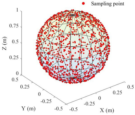
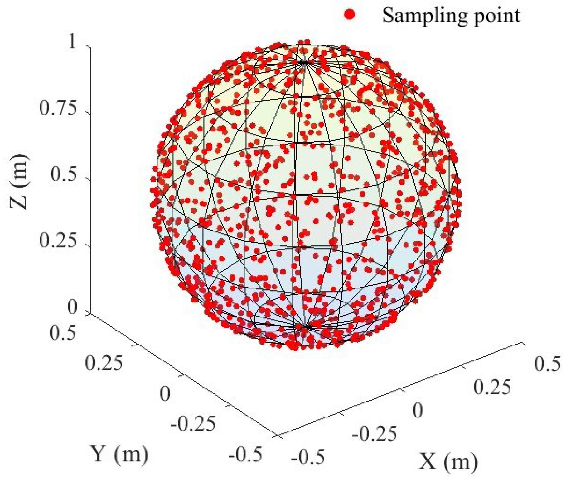
This section uses the same 7-DOF humanoid manipulator as in Section 7.1 and conducts comparative simulations to demonstrate the advantages of the proposed method in solving inverse kinematics for sampled target points. The sampled targets comprise 1000 randomly generated discrete points with a fixed end-effector orientation, distributed on the surface of a sphere (Figure 19). The sphere is centered at with a radius of . To facilitate inverse kinematics computation, the end-effector orientation is kept constant, and the orientation matrix is defined as in Equation (57).
Figure 19.
Schematic diagram of 1000 randomly sampled points.
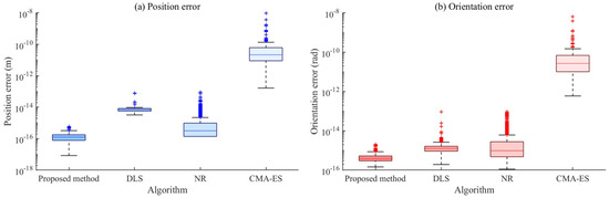
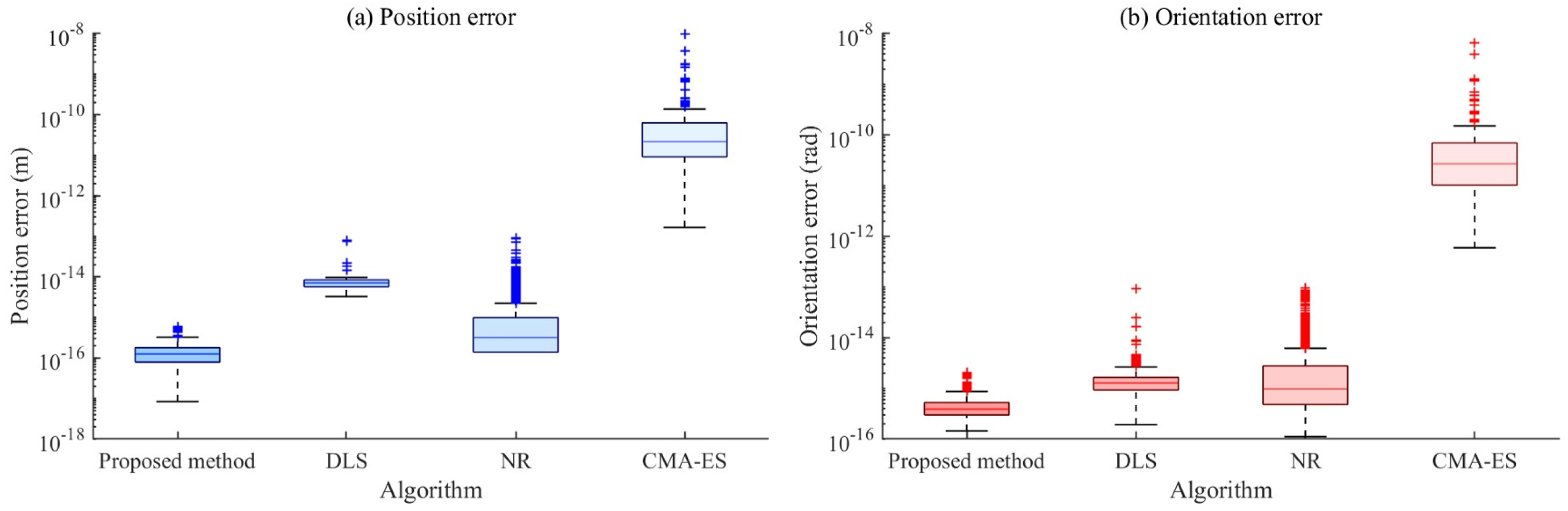
Figure 20 shows the position and orientation error results obtained by solving inverse kinematics for 1000 randomly sampled points using different methods. The results in Figure 20 indicate that, compared with the DLS algorithm, NR algorithm, and CMA-ES algorithm, the proposed method exhibits a more concentrated error distribution, lower error values, and fewer outliers in both position and orientation errors. Table 8 shows the basic parameter settings used for algorithm comparison.
Figure 20.
Error results obtained based on different methods.
Table 8.
Algorithm parameter configuration.
Table 9 compares the computation time, averaged over five runs, for solving the inverse kinematics of 1000 randomly sampled points using different methods. As shown in Table 9, the proposed method achieves the shortest average computation time among the DLS, NR, and CMA-ES methods, requiring only 0.6133 s to solve the 1000-point inverse kinematics problem.
Table 9.
Time performance of different methods for solving the inverse kinematics of randomly sampled points.
Table 10 summarizes the success-rate statistics of different methods over 1000 data sets. A solution is regarded as successful in position when the position error is below , and successful in orientation when the orientation error is below . As shown in Table 10, the proposed method achieves a higher success rate than the other methods, reaching 91.0% for position and 99.0% for orientation.
Table 10.
Statistical results of the solution success rates for different methods.
7.5. Discussion
The experiments show that, under joint-limit constraints, the feasible arm-angle domain may comprise multiple disconnected intervals, indicating that redundancy resolution naturally involves multiple branches and potential discontinuities. As a result, purely local search methods or heuristic branch-selection rules may miss feasible solutions or cause abrupt configuration changes. The proposed method explicitly identifies the feasible arm-angle domain first and then performs a one-dimensional search within this domain, making constraint handling and branch selection more transparent and controllable, thereby improving solution stability. Future work will incorporate configuration continuity into the optimization (e.g., via smoothing terms or branch-preservation mechanisms) to reduce configuration jumps near interval boundaries.
Trajectory-tracking simulations show stable end-effector errors and interference-free motion. Hardware experiments at key configurations also report no link collisions. Together, these results validate the method in terms of both accuracy and practical feasibility. These results suggest that the proposed approach not only satisfies end-effector pose requirements but also generates configuration sequences that respect joint limits and avoid interference. This makes it well suited to trajectory-tracking IK tasks. Since the experiments adopt a fixed end-effector orientation, it is worthwhile to extend the evaluation to tasks with path-varying orientations in order to assess configuration stability and robustness under pose-coupled motion.
In the comparative study, the proposed method exhibits a more concentrated error distribution with fewer outliers, lower average computation time, and higher success rates. These results indicate a better trade-off between efficiency and reliability, achieved through feasible-domain-based one-dimensional optimization. Its key advantage lies in reducing redundancy resolution to a one-dimensional search. This avoids the high computational cost of multi-dimensional iterations and intelligent optimization methods, making the approach more suitable for real-time applications.
The proposed method currently relies on offline computation, which may limit applicability for high-speed or dynamically changing tasks. End-effector orientations are assumed fixed, so performance under varying orientations or pose-coupled motions remains to be evaluated. Dynamic constraints, such as velocity, acceleration, and torque limits, are not yet incorporated, which may restrict applicability for load-sensitive or fast motions. When multiple disconnected feasible intervals exist, the one-dimensional interval search may require more iterations, increasing computation time. Additionally, although branch selection stability is improved, abrupt transitions may still occur near interval boundaries, requiring further smoothing mechanisms for full configuration continuity.
Future extensions may incorporate dynamic constraints such as velocity, acceleration, and torque limits. Online latency may also be further reduced through more efficient interval search strategies or controller-side implementation.
8. Conclusions
This paper presents an analytical inverse kinematics method for a humanoid 7-DOF redundant manipulator. The method explicitly determines the joint-limit-constrained feasible arm-angle domain and resolves redundancy via one-dimensional optimization. Simulation and comparative experiments verify the effectiveness of the proposed method. The hardware experiments provide proof-of-concept validation of its practical deployability on a real platform. Future work will address configuration continuity, pose-varying trajectories, and dynamic constraints.
Author Contributions
Conceptualization, D.J.; methodology, G.Z.; software, Y.T.; validation, D.J., Y.T.; formal analysis, B.Y.; investigation, G.Z.; resources, D.J.; data curation, J.Y.; writing—original draft preparation, G.Z.; writing—review and editing, B.T.; visualization, B.Y.; supervision, J.Y.; project administration, B.T.; and funding acquisition, B.T. All authors have read and agreed to the published version of the manuscript.
Funding
This research was funded by grants of the National Natural Science Foundation of China (Grant Nos. 52075530, 51575407, 51975324, 51505349, 61733011, 41906177); the Grants of Hubei Provincial Department of Education (D20191105); the Grants of National Defense Pre-Research Foundation of Wuhan University of Science and Technology (GF201705) and Open Fund of the Key Laboratory for Metallurgical Equipment and Control of Ministry of Education in Wuhan University of Science and Technology (2018B07, 2019B13) and Open Fund of Hubei Key Laboratory of Hydroelectric Machinery Design & Maintenance in China Three Gorges University (2020KJX02, 2021IKJX13).
Institutional Review Board Statement
Not applicable.
Informed Consent Statement
Not applicable.
Data Availability Statement
Data generated during the current study are available from the corresponding author on reasonable request. The data are available, but restrictions apply to the availability of these data, which were used under license for the current study and are not publicly available.
Conflicts of Interest
The authors declare no conflicts of interest. The funders had no role in the design of the study; in the collection, analyses, or interpretation of data; in the writing of the manuscript; or in the decision to publish the results.
References
- Cui, Z.; Pan, H.W.; Qian, D.H.; Peng, Y.; Han, Z.J. A Novel Inverse Kinematics Solution for a 7 DOF Humanoid Manipulator. In Proceedings of the 2012 IEEE International Conference on Mechatronics and Automation; IEEE: New York, NY, USA, 2012; pp. 2230–2234. [Google Scholar] [CrossRef] [Scilit]
- Yu, P.; Tan, N.; Zhong, Z.H.; Hu, C.; Qiu, B.B.; Li, C.S. Unifying obstacle avoidance and tracking control of redundant manipulators subject to joint constraints: A new data-driven scheme. IEEE Trans. Cogn. Dev. Syst. 2024, 16, 1861–1871. [Google Scholar] [CrossRef] [Scilit]
- Luo, M.R.; Tian, Y.N.; Li, E.; Chen, M.H.; Tan, M. A local obstacle avoidance and global planning method for the follow-the-leader motion of coiled hyper-redundant manipulators. IEEE Trans. Ind. Inform. 2024, 20, 6591–6602. [Google Scholar] [CrossRef] [Scilit]
- Wang, Y.C.; Liu, Y.; Leibold, M.; Buss, M.; Lee, J. Hierarchical incremental MPC for redundant robots: A robust and singularity-free approach. IEEE Trans. Robot. 2024, 40, 2128–2148. [Google Scholar] [CrossRef] [Scilit]
- Su, H.; Sheiban, F.J.; Qi, W.; Ovur, S.E.; Alfayad, S. A bioinspired virtual reality toolkit for robot-assisted medical application: Biovrbot. IEEE Trans. Hum. Mach. Syst. 2024, 54, 688–697. [Google Scholar] [CrossRef] [Scilit]
- Zhou, Z.Y.; Zhao, J.; Zhang, Z.Q. Synchronous planning of initial and target positions of redundant space manipulator based on deterministic configuration tree. Acta Astronaut. 2024, 219, 736–749. [Google Scholar] [CrossRef] [Scilit]
- Liu, T.L.; Yang, T.W.; Xu, W.F.; Mylonas, G.; Liang, B. Efficient inverse kinematics and planning of a hybrid active and passive cable-driven segmented manipulator. IEEE Trans. Syst. Man Cybern. Syst. 2022, 52, 4233–4246. [Google Scholar] [CrossRef] [Scilit]
- Xu, X.T.; Xie, H.B.; Wang, C. A kinematics method of hyper-redundant manipulators based on morphologic space constraints. IEEE Trans. Syst. Man Cybern. Syst. 2024, 55, 238–250. [Google Scholar] [CrossRef] [Scilit]
- Chen, Q.H.; Li, M.T.; Wu, H.X.; Liu, W.Q.; Peng, J.Q. Design, self-calibration and compliance control of modular cable-driven snake-like manipulators. Mech. Mach. Theory 2024, 193, 105562. [Google Scholar] [CrossRef] [Scilit]
- Hernandez-Barragan, J.; Lopez-Franco, C.; Arana-Daniel, N.; Alanis, A.Y.; Lopez-Franco, A. A modified firefly algorithm for the inverse kinematics solutions of robotic manipulators. Integr. Comput. Aided Eng. 2021, 28, 257–275. [Google Scholar] [CrossRef] [Scilit]
- Dereli, S.; Köker, R. Strengthening the PSO algorithm with a new technique inspired by the golf game and solving the complex engineering problem. Complex Intell. Syst. 2021, 7, 1515–1526. [Google Scholar] [CrossRef] [Scilit]
- Ma, W.L.; Du, Q.L.; Zhu, R.; Han, W.T.; Chen, D.J.; Geng, Y.F. Research on inverse kinematics of redundant robotic arms based on flexibility index. IEEE Robot. Autom. Lett. 2024, 9, 7262–7269. [Google Scholar] [CrossRef] [Scilit]
- Woliński, Ł.; Wojtyra, M. An inverse kinematics solution with trajectory scaling for redundant manipulators. Mech. Mach. Theory 2024, 191, 105493. [Google Scholar] [CrossRef] [Scilit]
- Tong, Y.C.; Liu, J.G.; Liu, Y.W.; Yuan, Y. Analytical inverse kinematic computation for 7-DOF redundant sliding manipulators. Mech. Mach. Theory 2021, 155, 104006. [Google Scholar] [CrossRef] [Scilit]
- Guo, D.S.; Li, A.F.; Cai, J.H.; Feng, Q.S.; Shi, Y. Inverse kinematics of redundant manipulators with guaranteed performance. Robotica 2022, 40, 170–190. [Google Scholar] [CrossRef] [Scilit]
- Shimizu, M.; Kakuya, H.; Yoon, W.K.; Kitagaki, K.; Kosuge, K. Analytical inverse kinematic computation for 7-DOF redundant manipulators with joint limits and its application to redundancy resolution. IEEE Trans. Robot. 2008, 24, 1131–1142. [Google Scholar] [CrossRef] [Scilit]
- Faria, C.; Ferreira, F.; Erlhagen, W.; Monteiro, S.; Bicho, E. Position-based kinematics for 7-DoF serial manipulators with global configuration control, joint limit and singularity avoidance. Mech. Mach. Theory 2018, 121, 317–334. [Google Scholar] [CrossRef] [Scilit]
- Dou, R.T.; Yu, S.B.; Li, W.Y.; Chen, P.; Xia, P.P.; Zhai, F.C.; Yokoi, H.; Jiang, Y.L. Inverse kinematics for a 7-DOF humanoid robotic arm with joint limit and end pose coupling. Mech. Mach. Theory 2022, 169, 104637. [Google Scholar] [CrossRef] [Scilit]
- Yan, L.; Mu, Z.G.; Xu, W.F. Analytical inverse kinematics of a class of redundant manipulator based on dual arm-angle parameterization. In Proceedings of the 2014 IEEE International Conference on Systems, Man, and Cybernetics (SMC); IEEE: New York, NY, USA, 2014; pp. 3744–3749. [Google Scholar] [CrossRef] [Scilit]
- Yu, C.; Jin, M.H.; Liu, H. An analytical solution for inverse kinematic of 7-DOF redundant manipulators with offset-wrist. In Proceedings of the 2012 IEEE International Conference on Mechatronics and Automation; IEEE: New York, NY, USA, 2012; pp. 92–97. [Google Scholar] [CrossRef] [Scilit]
- Jung, D.; Yoo, Y.; Koo, Y.J.; Koo, J.; Song, M.; Won, S. A Novel Redundancy Resolution Method to Avoid Joint Limits and Obstacles on Anthropomorphic Manipulator. In Proceedings of the SICE Annual Conference 2011; IEEE: New York, NY, USA, 2011; pp. 924–929. Available online: https://ieeexplore.ieee.org/abstract/document/6060641 (accessed on 13 March 2026).
- Mu, Z.G.; Yuan, H.; Xu, W.F.; Liu, T.L.; Liang, B. A segmented geometry method for kinematics and configuration planning of spatial hyper-redundant manipulators. IEEE Trans. Syst. Man Cybern. Syst. 2018, 50, 1746–1756. [Google Scholar] [CrossRef] [Scilit]
- An, H.H.; Clement, W.I.; Reed, B. Analytical inverse kinematic solution with self-motion constraint for the 7-DOF restore robot arm. In Proceedings of the 2014 IEEE/ASME International Conference on Advanced Intelligent Mechatronics; IEEE: New York, NY, USA, 2014; pp. 1325–1330. [Google Scholar] [CrossRef] [Scilit]
- Zhong, X.Y.; Wang, H.L.; Liu, C.J.; Chen, Q.J. Inverse Kinematics Resolution Method for Arm Angle Parameterized Redundant Robotic Arm Based on Minimum Motion Transformation. J. Mech. Eng. 2023, 59, 40–49. [Google Scholar] [CrossRef] [Scilit]
- Chen, Y.L.; Zhang, X.M.; Huang, Y.J.; Wu, Y.B.; Ota, J. Kinematics optimization of a novel 7-DOF redundant manipulator. Robot. Auton. Syst. 2023, 163, 104377. [Google Scholar] [CrossRef] [Scilit]
- Elias, A.J.; Wen, J.T. Redundancy parameterization and inverse kinematics of 7-DOF revolute manipulators. Mech. Mach. Theory 2024, 204, 105824. [Google Scholar] [CrossRef] [Scilit]
- Li, G.F.; Xiao, F.; Zhang, X.F.; Tao, B.; Jiang, G.Z. An inverse kinematics method for robots after geometric parameters compensation. Mech. Mach. Theory 2022, 174, 104903. [Google Scholar] [CrossRef] [Scilit]
- Kreutz-Delgado, K.; Long, M.; Seraji, H. Kinematic analysis of 7-DOF manipulators. Int. J. Robot. Res. 1992, 11, 469–481. [Google Scholar] [CrossRef] [Scilit]
- Hollerbach, J.M. Optimum kinematic design for a seven degree of freedom manipulator. In Robotics Research: The Second International Symposium; MIT Press: Cambridge, MA, USA, 1985; pp. 215–222. Available online: https://dspace.mit.edu/bitstream/handle/1721.1/5607/AIM-882.pdf?sequence=2 (accessed on 13 March 2026).

Disclaimer/Publisher’s Note: The statements, opinions and data contained in all publications are solely those of the individual author(s) and contributor(s) and not of MDPI and/or the editor(s). MDPI and/or the editor(s) disclaim responsibility for any injury to people or property resulting from any ideas, methods, instructions or products referred to in the content. |
© 2026 by the authors. Licensee MDPI, Basel, Switzerland. This article is an open access article distributed under the terms and conditions of the Creative Commons Attribution (CC BY) license.